Dear Customer,
Thank you for choosing your Windrose vehicle.
Please read this Owner's Manual carefully before operating the vehicle for the first time. It contains important information about vehicle features, safe operation, maintenance requirements, and technical specifications. Familiarizing yourself with this information will help ensure safe driving and optimal vehicle performance.
Due to different vehicle configurations and optional equipment, the vehicle delivered to you may differ slightly from the descriptions or illustrations in this manual. Windrose reserves the right to modify vehicle design, specifications, and equipment without prior notice as part of continuous product improvement.
The information, illustrations, and technical data in this manual were accurate at the time of publication. They are provided for reference only and do not constitute a contractual commitment.
No part of this Owner's Manual may be reproduced or transmitted in any form without prior written permission from Windrose.
Note: The cover images and illustrations in this manual are for reference purposes only. Actual vehicle appearance and specifications may vary.
Table of Contents
Notes to Users
↑ TopBefore You Drive
This vehicle is a battery electric tractor unit.
During daily operation and maintenance, follow all warnings and instructions provided in this Owner's Manual (referred to below as "this manual") to avoid vehicle damage or personal injury.
Before operating the vehicle for the first time, read this manual carefully to become familiar with its features and operating requirements. If you encounter any issues during use, contact the Windrose service hotline.
The copyright of this manual is owned by Windrose. No part of this manual may be reproduced, transmitted, or distributed without prior written permission from Windrose.
Windrose reserves the right to update the contents of this manual without prior notice as part of continuous product improvement. Please refer to the electronic Owner's Manual available in the center display or the Windrose mobile app for the latest vehicle information.
Windrose website:
Windrose service hotline:You may search for "Windrose" in the official mobile app store to download the application.
NoteAbbreviations are introduced in the format "full name (abbreviation)" when first mentioned. Thereafter, the abbreviation will be used.
Warning Description
↑ TopBefore You Drive
The following signal words and symbols are used in this manual:
WarningIndicates a hazardous situation which, if not avoided, could result in serious injury or death.
Notice
↑ TopNoticeIndicates a situation that may cause damage to the vehicle or its components.
Note
↑ TopNoteProvides additional helpful information or operational guidance.
Environmental protection
↑ TopEnvironmental protectionIndicates information related to environmental protection or energy efficiency.
Asterisk
↑ TopAn asterisk (*) after a feature name indicates that the function applies only to certain vehicle models or optional configurations.
Illustration information
↑ Top
This arrow indicates the exact location of the object as shown in the picture.
This arrow indicates the movement direction of the object as shown in the picture.
This arrow indicates the rotation direction of the object as shown in the picture.
This arrow indicates the flipping direction of the object as shown in the picture.
Environmental Protection
↑ TopBefore You Drive
Windrose is committed to sustainable development and environmental protection. This vehicle is designed to improve energy efficiency and reduce emissions. You can contribute to environmental protection by driving responsibly and operating the vehicle in an energy-efficient manner.
Operating Safety
Before You Drive
Observe the maximum permissible gross vehicle weight and axle load at all times. Do not overload the vehicle, as overloading may result in vehicle damage, loss of control, or personal injury.
Replace any seat belt that has been subjected to impact forces in a collision, even if no visible damage is
Warningpresent.
Warning
Never coast downhill in neutral. This removes drive motor braking and may result in loss of vehicle control.
Before driving, adjust the seat to the correct position. An incorrect seating position may cause fatigue, unexpected seat movement, or loss of vehicle control. Ensure the seat position allows proper use of the seat belt.
Seat belts are essential safety devices. All occupants must wear seat belts correctly whenever the vehicle is in motion.
Do not excessively recline the seat backrest while driving. In an emergency braking event, an improper seating position may
reduce seat belt effectiveness.
Do not exceed 19 mph in any of the following situations:
Entering or exiting non-motorized vehicle lanes, railroad crossings, sharp bends, narrow roads, or bridges.
Making a U-turn, turning, or descending a steep grade.
Visibility is less than 164.0 ft due to fog, rain, snow, dust, or hail.
Driving on icy, snow-covered, or muddy roads.
Towing a disabled vehicle.
↑ Top
NoticeWhen driving near a radio astronomy observatory, maintain a safe distance. Radar-equipped vehicles may cause electromagnetic interference to observatory equipment.
Genuine Parts
Before You Drive
Windrose will not provide warranty coverage for parts under the following circumstances:
Unauthorized vehicle modifications, particularly to systems related to driving safety (e.g., high-voltage systems, electrical systems, braking, steering, or TBOX).
Tampering with the vehicle's OBD system.
Use of non-approved parts or fluids that result in safety risks or vehicle damage.
Failure to provide documentation confirming the use of approved fluids during the warranty period.
Failure to service the vehicle at a Windrose authorized service center in accordance with maintenance requirements.
Data Security
↑ TopBefore You Drive
In accordance with applicable laws and regulations, Windrose collects and processes vehicle data including location information, driving behavior data, audio and video recordings, and personal information.
Windrose implements appropriate technical and organizational measures to protect such data in compliance with applicable data protection regulations and industry standards.
Vehicle Modification
Before You Drive
↑ TopMaterials required prior to modification
Any vehicle modification must comply with applicable technical and regulatory requirements. Prior to modification, relevant technical documentation must be submitted to Windrose.
The documentation shall include at minimum:
Purpose and operating conditions of the modified vehicle.
Gross vehicle mass and axle loads after modification.
Overall dimensions of the modified vehicle (including working configuration).
Body floor height above ground level.
Body mounting method.
Subframe schematic drawing.
Vehicle Scrapping
Before You Drive
↑ TopVehicles that no longer meet roadworthiness requirements must be disposed of in accordance with applicable environmental regulations.
Vehicle scrapping and high-voltage battery recycling must be performed by Windrose or authorized recycling organizations.
WarningImproper disposal of high-voltage batteries may cause fire or environmental damage. Do not dismantle or discard high-voltage batteries without authorization.
Recycle of high-voltage battery
Windrose will test the capacity and condition of the high-voltage battery, and recycle the high-voltage battery according to applicable laws, regulations and market conditions at that time.
Recycling of high-voltage battery: Recycling and follow-up processing should be done by Windrose or a third-party recycling organization designated by Windrose.
Transportation of high-voltage battery: High voltage batteries are transported by a professional transportation agency. Contact the Windrose authorized service center to notify a professional recycling agency for processing.
Warning
Do not dispose of or discard the used high-voltage batteries to avoid accidental fire or serious pollution to the environment.
Do not hand over waste high-voltage batteries to other units or individuals. You will be held responsible for any environmental pollution or safety accidents caused by disassembling of high-voltage batteries without permission.
Eco Driving
Before You Drive
The following practices will help maximize driving range and energy efficiency:
Maintain a steady speed and avoid harsh acceleration or braking.
Keep the vehicle in good working condition through regular maintenance.
Never coast in neutral gear, as this will cause insufficient lubrication of the E-axle, leading to component damage.
Winter Driving
↑ TopBefore You Drive
Preparation for winter driving
Use high-quality coolant based on the lowest temperature, and the freezing point of the coolant should be lower than local minimum temperature.
Ensure that the battery is fully charged at all times to prevent the battery from freezing under low temperatures.
Use of vehicle coolant in winter
↑ TopIn the cold season or when the vehicle is parked in a cold place, the antifreeze properties of the coolant should be ensured. Please use the coolant recommended by Windrose.
Precautions for winter driving
It is recommended to use snow chains or snow tires.
Avoid sudden acceleration, sudden braking, and sharp turns at high speeds.
When driving on roads covered with snow and ice, keep driving at a low speed to ensure better service braking.
Maintain a reasonable distance between vehicles (increase the distance between vehicles as driving in rainy and snowy
After installing the snow chains, start the vehicle and observe whether the chains are loose or whether the tires are not properly mounted.
↑ TopWarningWhen using snow chains, it is forbidden to exceed the maximum effective driving speed to avoid accidents.
day or icy roads may increase the service brake distance).
Use of Snow Chains
Before You Drive
When using snow chains, pay attention to the following:
It is recommended to use snow chains when driving on roads covered with thick layers of snow or ice.
Snow chains must be compatible with the tire size and type fitted to the vehicle.
Fit snow chains to the outer tires of the drive axle (both sides).
Take care not to damage the tires when fitting or removing snow chains.
Notice
 When driving on long roads without snow and ice, remove the snow chains.
Ensure the snow chains do not contact or interfere with any vehicle components while driving.
Fit and remove snow chains only when the vehicle is parked on level ground.
Driving in Tropical and High Temperature Areas
Before You Drive
Check the condition of the vehicle before driving:
Check that the coolant level is within the normal range and inspect for leaks.
Do not leave flammable items (e.g., lighters, aerosol products, perfumes) on the instrument panel or in direct sunlight for extended periods. High temperatures may cause pressurized containers to rupture and create a fire hazard.
During driving, pay attention to the following:
lamps become illuminated, stop driving immediately and
contact a Windrose authorized service center.
Notice the tire pressure and tire temperature. If the tire pressure or tire temperature is abnormal, immediately stop driving and let the tires cool down naturally. Do not depressurize and cool down the tires by means of water spraying or deflation, as this will easily accelerate tire aging and wear, and may result in tire bursts in severe cases.
If tire bursts happen during driving, immediately press the hazard warning switch, hold the steering wheel with your hands at the 9 & 3 o'clock position without turning, and apply the brake pedal intermittently to slow the vehicle gradually and alert other road users.
Monitor tire pressure and tire temperature.
If either is abnormal, stop the vehicle as soon as it is safe to do so and allow the tires to cool naturally. Do not cool tires using water or by deflating them, as this may accelerate tire ageing and increase the risk of a blowout.
Keep an eye on the indicators and warning lamps in the instrument cluster, and if the vehicle-related MILs or warning
Driving on Bumpy and Slippery Roads
Before You Drive
Pay attention to the following when driving on bumpy and slippery roads:
On bumpy roads, reduce speed to improve comfort and minimize wear to suspension and shock-absorbing components.
On slippery roads, reduce speed and apply the brakes gently to prevent loss of traction and vehicle sideslip.
If the vehicle begins to sideslip on wet or slippery surfaces, reduce speed smoothly using the service brake and avoid sudden steering inputs.
Ramp Driving
↑ TopBefore You Drive
Precautions for uphill driving
If the vehicle rolls back when starting on an incline, depress the brake pedal immediately, apply the electronic parking brake, and then restart the driving procedure.
When climbing, maintain a low and steady speed. Apply the accelerator progressively and avoid sudden acceleration or braking.
Precautions for downhill driving
Reduce speed before the descent so the vehicle enters the downhill grade at a controlled speed.
Never coast downhill in neutral. This removes drive motor braking and may result in loss of vehicle control.
Before descending, ensure the braking system is functioning correctly. If a fault is suspected, rectify the issue before continuing.
Avoid sharp steering inputs on downhill roads to reduce rollover risk.
On long descents, avoid continuous braking. Use appropriate speed control and braking techniques to prevent brake overheating and potential brake fade.
Reporting Safety Defects
↑ TopBefore You Drive
If you suspect the vehicle has a safety-related defect, stop the vehicle in a safe location as soon as practicable and contact Windrose customer support or a Windrose authorized service station immediately.
Windrose may issue safety notices, service campaigns, or recalls where required by applicable laws and regulations. In the United States, vehicle safety defects and recalls are reported to and handled by the National Highway Traffic Safety Administration (NHTSA). If you believe your vehicle has a safety defect, you may contact NHTSA at 1-888-327-4236 (TTY: 1-800-424-9153) or online at www.nhtsa.gov. Follow all safety instructions and service campaign requirements provided by Windrose.
Windrose service hotline: [US CONTACT DETAILS TO BE CONFIRMED]
Windrose service website: [US SERVICE WEBSITE TO BE CONFIRMED]
Authorized service network: [US SERVICE NETWORK TO BE CONFIRMED]
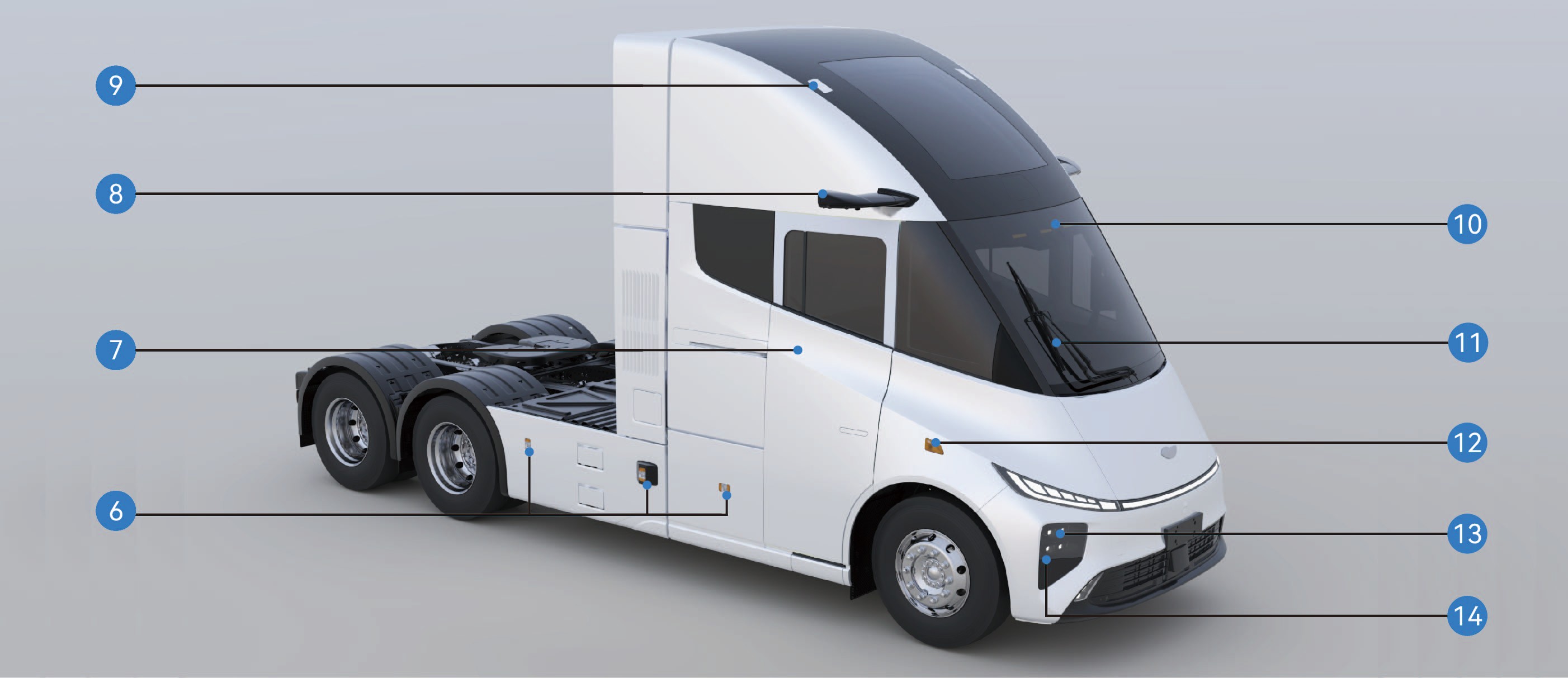
Overview of Vehicle Exterior
Vehicle Identification
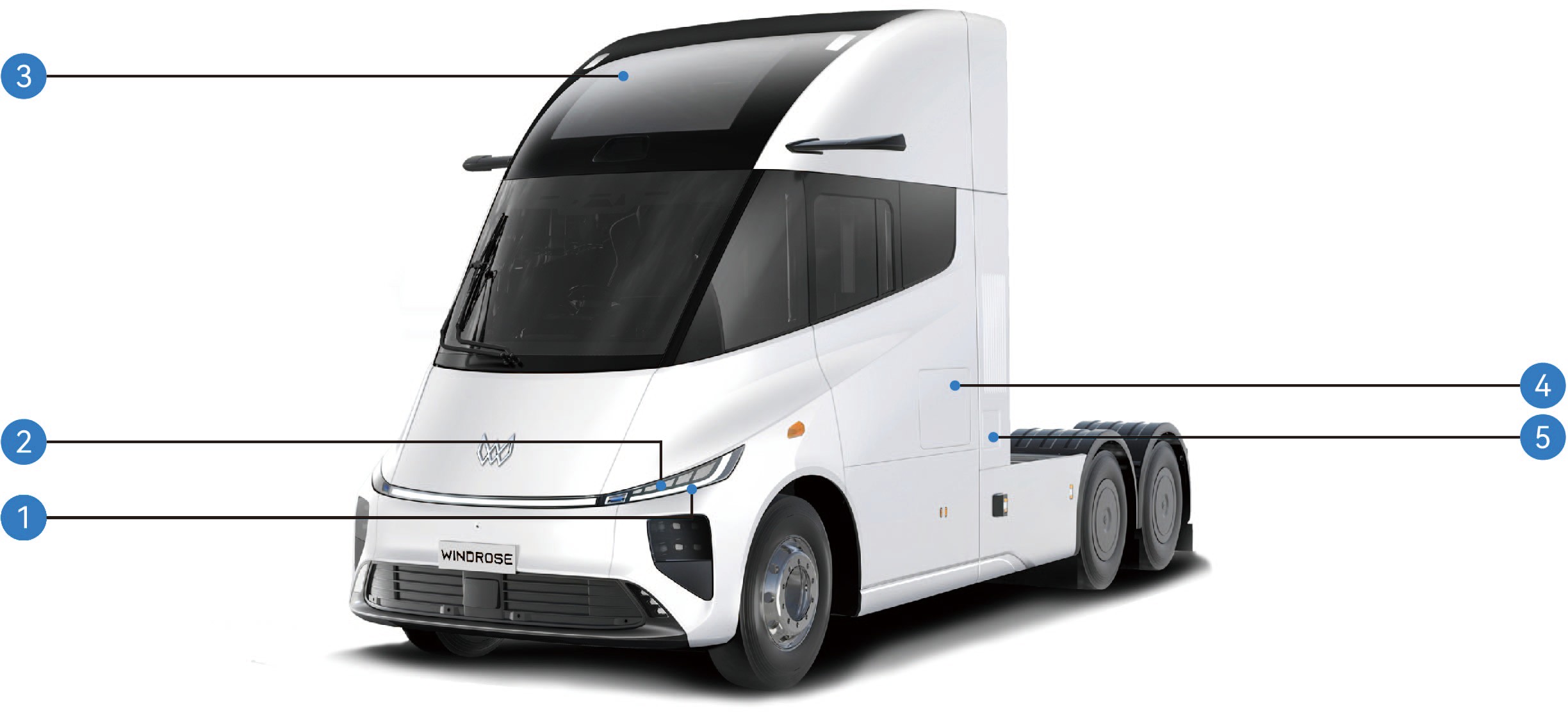
Front indicator lamp/daytime running lamp
Parking lamp 3. Panoramic sunroof
4. Side toolbox 5. Charging port
|
|
|
|
|
|
|---|---|---|---|---|---|
|
|
|
|
|
|
|
|
|
|
|
|
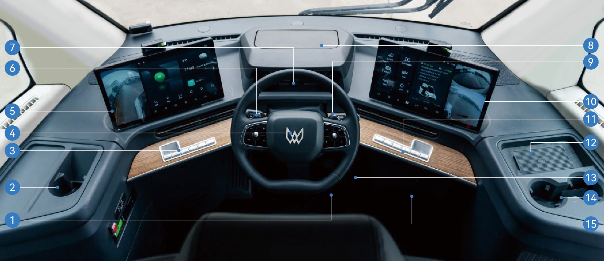
Overview of Vehicle Interior
Vehicle Identification
|
|
2. |
|
3. |
|
|---|---|---|---|---|---|
|
|
5. |
|
6. |
|
|
|
8. |
|
9. |
|
|
|
11. |
|
12. |
|
|---|---|---|---|---|---|
|
|
14. |
|
15. |
|
Vehicle Nameplate and VIN
Vehicle Identification
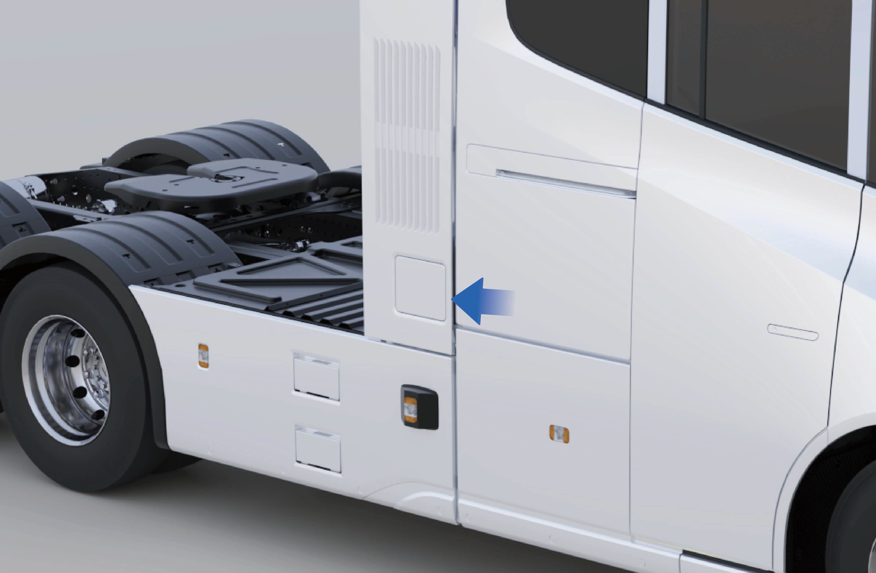
Vehicle nameplate
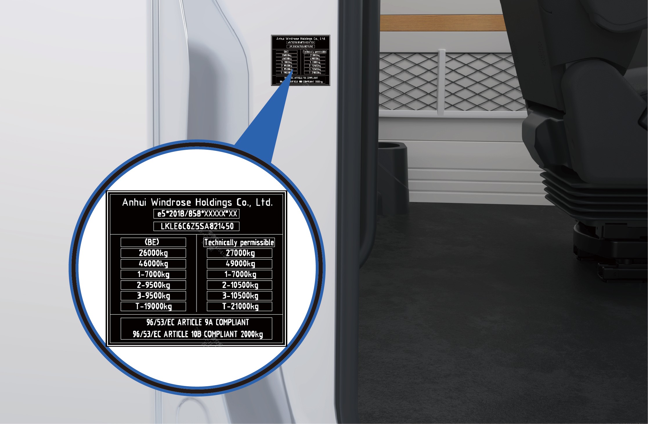
The vehicle nameplate is located on the right sliding door frame (C-pillar) of the vehicle.
The nameplate displays the following information:
Manufacturer's name
Whole Vehicle Type Approval (WVTA) number
Vehicle Identification Number (VIN)
Intended registration maximum permissible mass
Technically permissible maximum laden mass
Other regulatory information required by applicable regulations
Vehicle identification number
The Vehicle Identification Number (VIN) is stamped on the right-hand frame side member, near the centerline of the front axle.
Location of Motor Nameplate and Code
Vehicle Identification
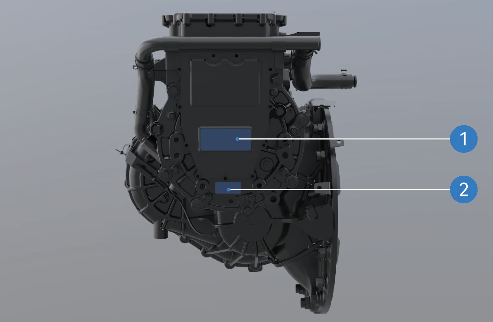
Location of motor nameplate
Location of motor SN
Notice
The motor rubbing (impression) of the serial number is provided together with the motor documentation when the vehicle leaves the factory. Please keep this document for future reference.
As traction motors supplied by different manufacturers may vary, the information shown on the motor nameplate and related documentation may differ. Please refer to the actual product.
Microwave / RF Transparency of Windshield Vehicle Identification
The windshield of this vehicle does not contain metallic coatings that interfere with radio-frequency (RF) signal transmission.
Electronic toll collection (ETC) devices, toll tags, telematics equipment, or other RF-based devices may therefore be installed on the windshield in accordance with the installation instructions provided by the equipment manufacturer.
Electric Sliding Door
↑ TopAccess to Vehicle
An electric sliding door is installed on the right side of the vehicle. The door can be opened or closed using several operating methods.
Operating instructions
Exterior operation
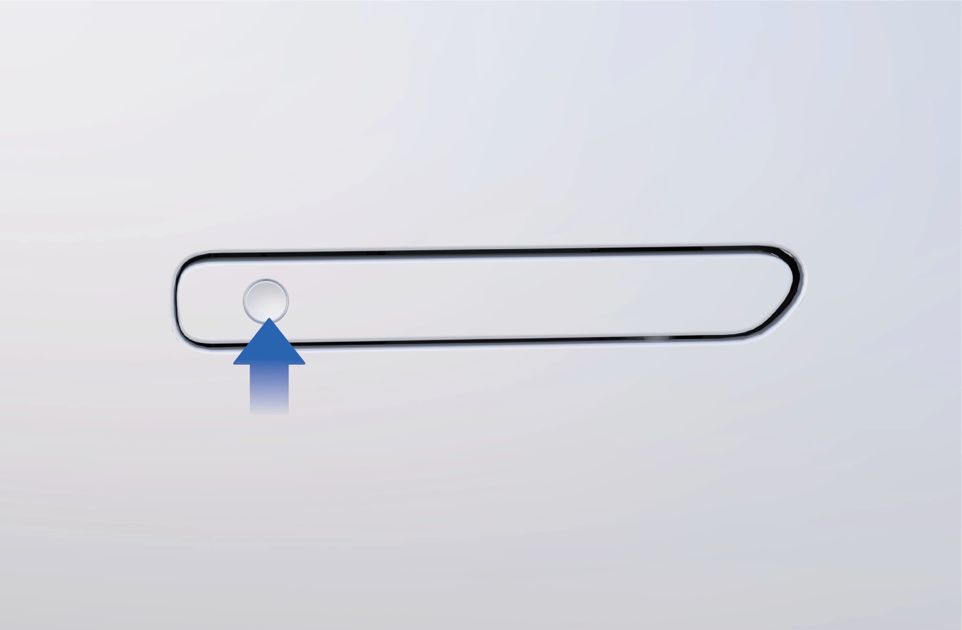
↑ TopElectric: When the vehicle is unlocked, press the flush door handle switch. The electric sliding door will automatically open or close.
Manual: When the vehicle is unlocked:
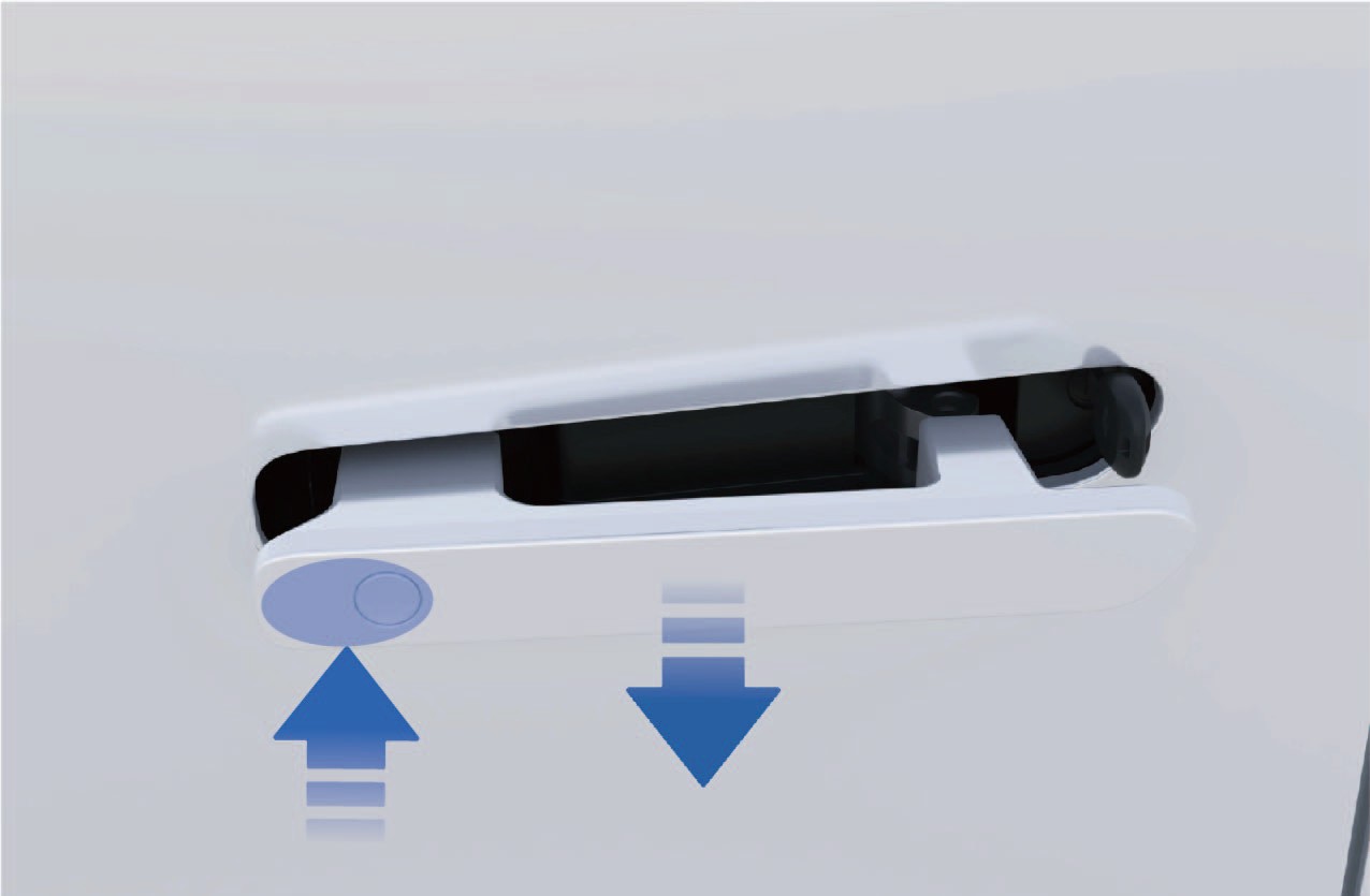
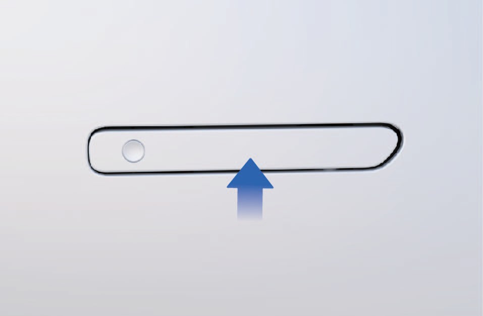
1. Press the front end of the flush door handle to release it.
2. Pull the handle outward to unlock the sliding door.
3. Slide the door open manually.
Enter the vehicle
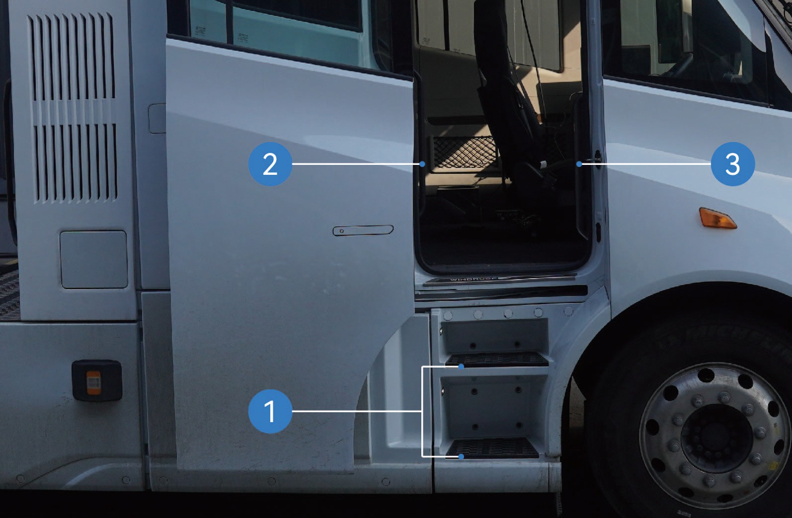
After the electric sliding door is opened, enter the cab using the following steps:
Face the door and grasp the left and right grab handles with both hands.
Place one foot on the lower step and pull yourself upward.
Place your other foot on the upper step.
Move your lower hand to a higher position on the grab handle.
Step into the vehicle cab.
Slipping or falling while entering or exiting the vehicle may result in personal injury.
Wet or dirty footwear significantly increases the risk of slipping. Exercise extra caution when entering or exiting the cab.
Always maintain three-point contact with the vehicle when entering or exiting the cab (two hands and one foot, or two feet and one hand).
Never jump from the vehicle.
Interior operation
When the vehicle is unlocked:
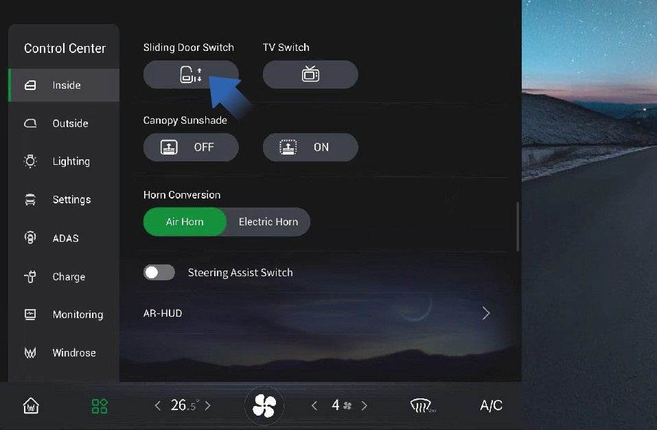
Select "Control Center" on the vehicle information screen.
Switch to the "Inside" interface.
Press the "Sliding Door" control button to open or close the electric sliding door
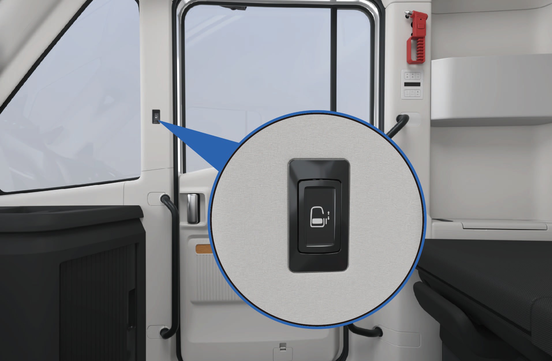
Electric: When the vehicle is unlocked, press the switch located on the B-pillar trim panel in front of the sliding door to open or close the door.
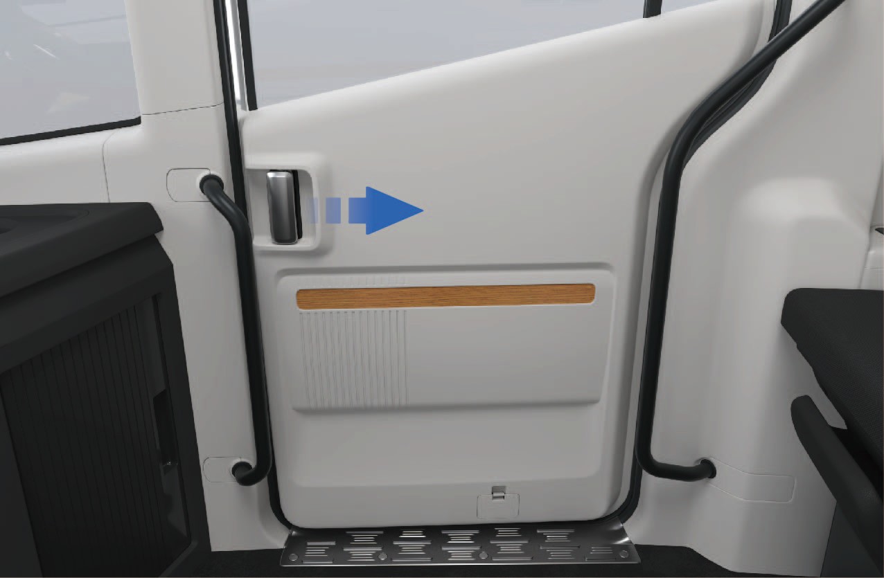
Manual: If the sliding door is closed, pull the interior handle rearward to unlock the door and slide it open manually.
If the sliding door is open, hold the interior handle and slide the door forward to close it.
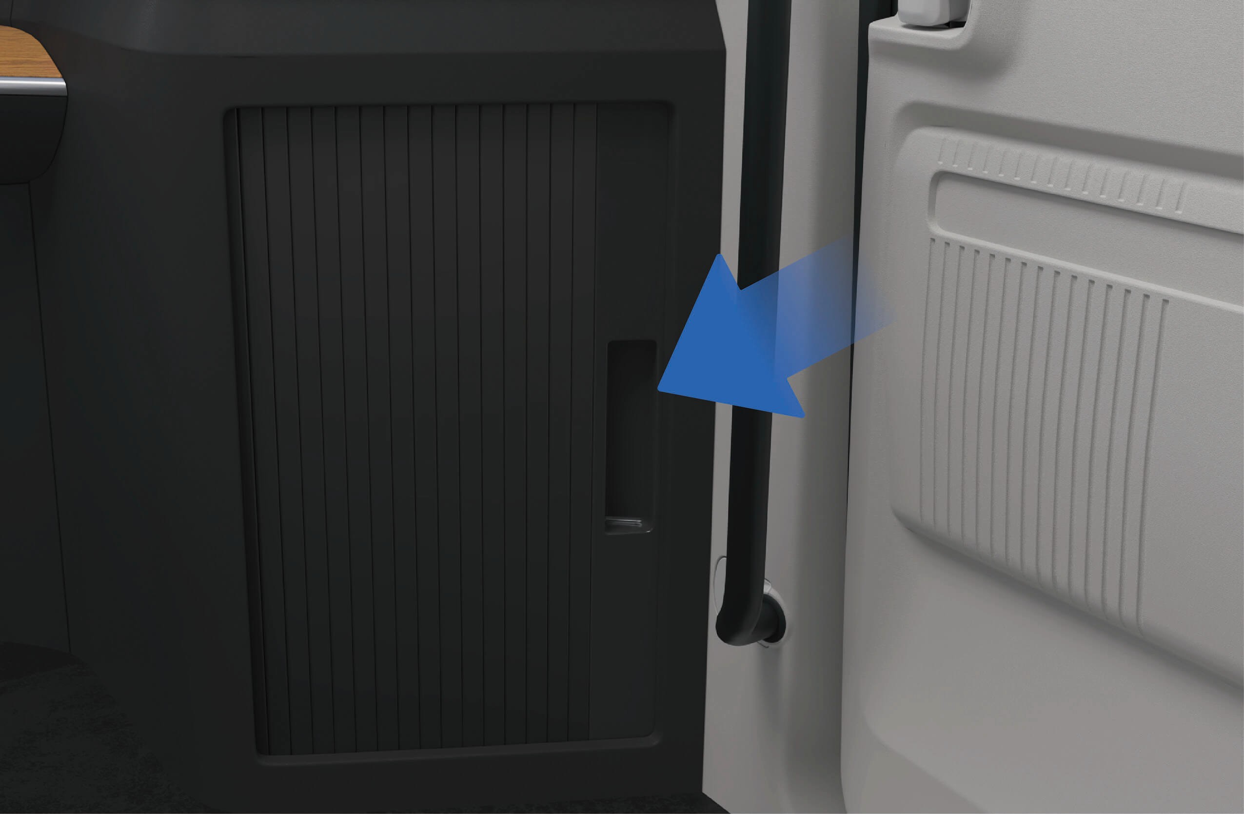
In-vehicle emergencies
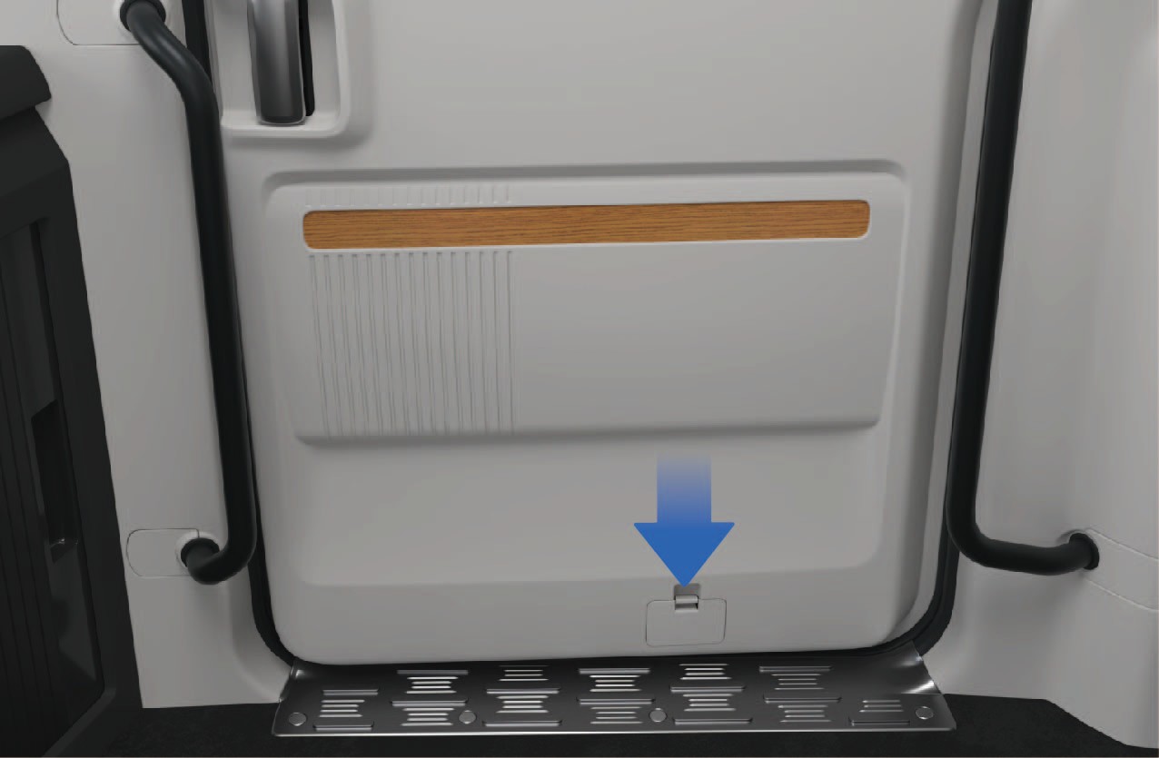
If the electric switch or interior handle fails:
Remove the lower cover plate of the sliding door protection panel.
Pull the emergency release cable to manually unlock the sliding door.
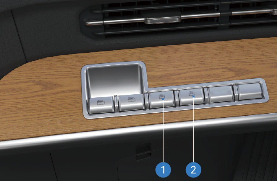
Central lock switch
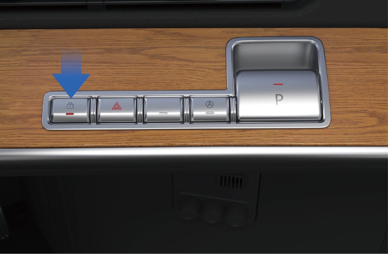
After the sliding door is closed:
Press the central locking switch located in the button cluster on the right side of the instrument panel to lock the sliding door.
The status indicator will illuminate when the door is locked.
Press the switch again to unlock the door.
Manual mode of sliding door
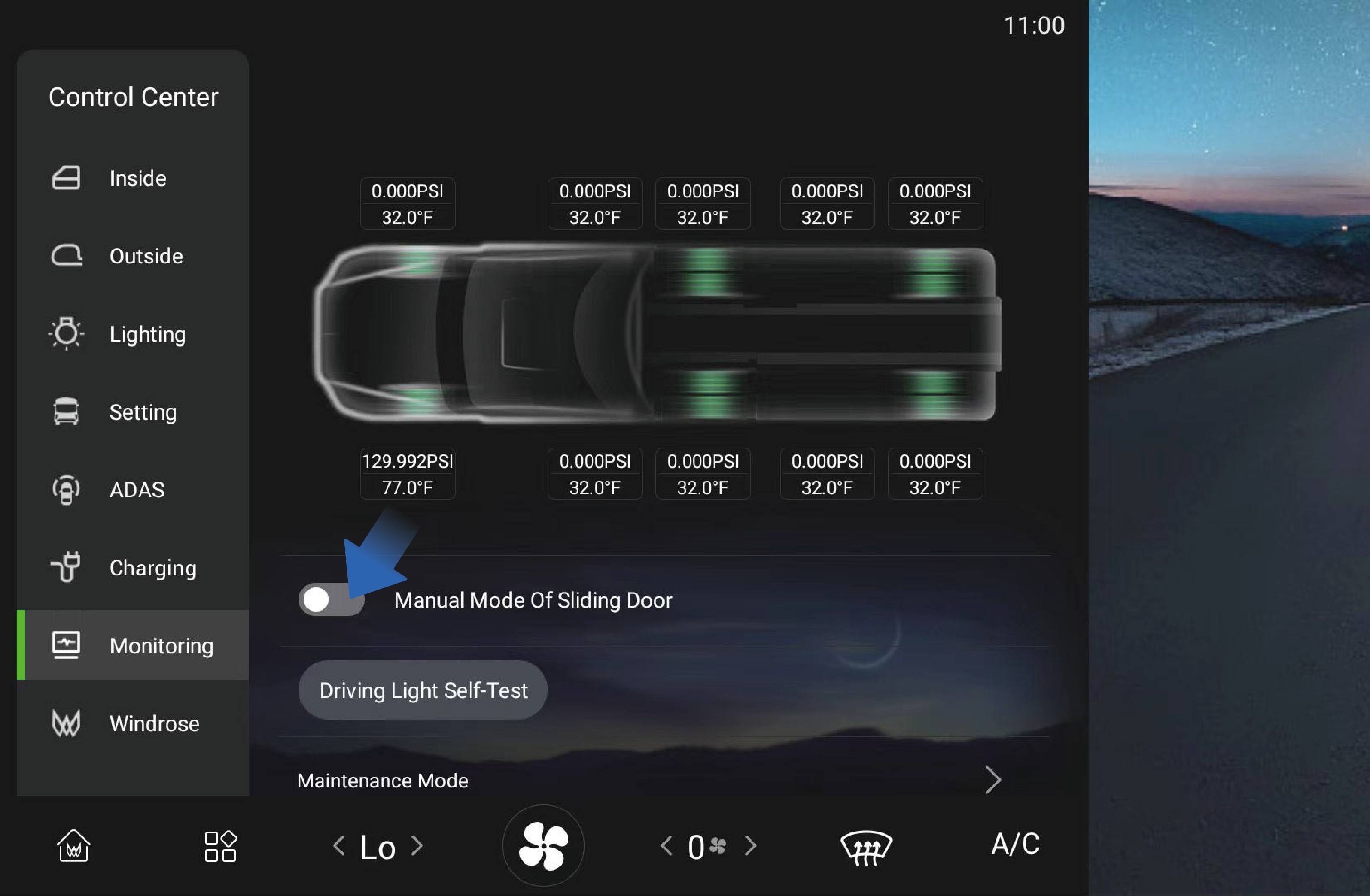
The manual mode can be activated or deactivated through the vehicle information screen:
Select "Control Center".
Switch to the "Monitoring" interface.
Select "Sliding Door Manual Mode".
↑ TopWhen manual mode is enabled, the sliding door can only be operated manually.
Sliding Door Anti-Pinch Function
During automatic closing, if the sliding door detects an obstacle, the door will stop closing and automatically reverse to the open position.
Precautions
↑ TopWarningThe anti-pinch function is only active during electric closing operation. It is not active when the door is operated manually.
Seat Belt
↑ TopAccess to Vehicle
The driver and front passenger seats are equipped with seat belts. Seat belts help prevent or reduce injury to occupants during emergency braking or a collision.
Operating instructions
↑ TopThe driver seat belt is located on the left side of the driver seat and can be pulled out directly to fasten.
The front passenger seat belt is located on the right side of the front passenger seat. When the passenger seat is occupied, remind the passenger to wear the seat belt correctly before the vehicle begins moving.
Proper Seat Belt Use
Observe the following guidelines when wearing a seat belt:
• The lap portion of the belt should lie low across the pelvis (hips) and not across the abdomen.
• The belt should fit snugly against the body without twists.
• The shoulder portion should pass across the middle of the shoulder.
• Never position the belt across the neck or under the arm.
• After fastening the seat belt, pull the shoulder portion upward to ensure the lap portion fits firmly across the hips.
• Always verify that the seat belt is properly latched before driving.
Seat Belt Reminder
If the driver's seat belt is not fastened, the seat belt warning lamp on the instrument cluster will illuminate.
Once the driver fastens the seat belt, the warning lamp will turn off.
Cleaning Seat Belts
If a seat belt becomes dirty, clean it using mild soap and water.
1. Pull the seat belt fully out and secure it in place.
2. Apply a mild soap solution to the contaminated area.
3. Gently clean the belt with a soft brush or cloth.
4. Rinse with clean water if necessary.
5. Allow the seat belt to dry completely before retracting it.
Do not retract a wet seat belt into the retractor mechanism.
Precautions
WarningAll occupants must wear seat belts properly while the vehicle is in motion. Correct use of seat belts significantly reduces the risk of injury during emergency braking or a collision.
Failure to wear a seat belt or improper use may result in serious injury or death.
Do not sit in areas that are not equipped with a seat and seat belt.
Do not use a seat belt that is damaged or malfunctioning.
Each seat belt is designed for one occupant only. Never share a seat belt with another person.
Never place the shoulder belt around the neck or under the arm.
Do not remove, modify, or tamper with the seat belt system.
Do not use bleach, dyes, or chemical solvents to clean seat belts, as these may weaken the belt material.
Power Window
↑ TopAccess to Vehicle
The side windows can be operated using the window control switches located on the left side of the instrument panel or on the sleeper control panel.
The vehicle is equipped with an automatic window closing function. When the vehicle is powered off and locked, the windows will automatically close if they are not already fully closed.
Operating instructions
Window adjustment via combination button
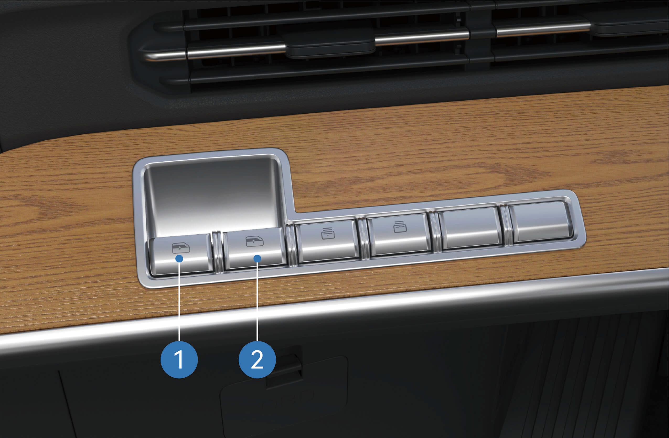
Left window control switch: Press and hold the up and down switch buttons to control the opening of the left window; Press and release the left window control switch button up and down to raise or lower the left window with one click.
Right window control switch: Press and hold the up and down switch buttons to control the opening of the right window; Press and release the right window control switch button up
and down to raise or lower the right window with one click.
Window adjustment via sleeper switch
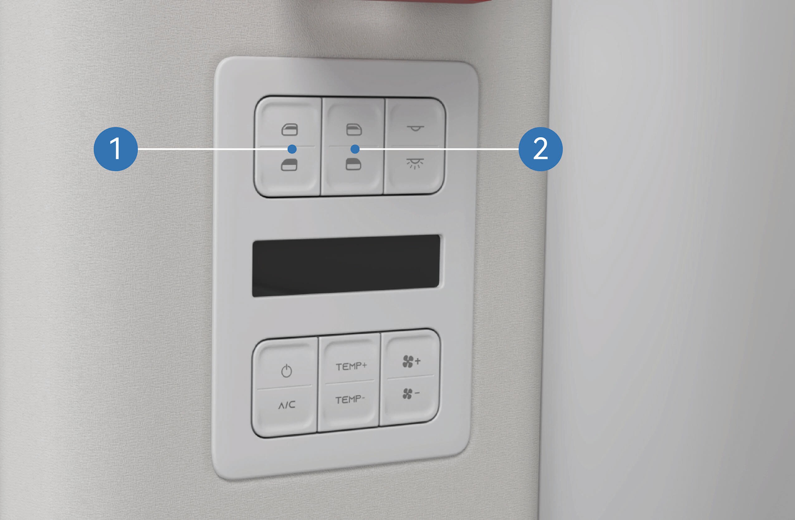
Left window control switch: Press and hold the up and down
↑ Topautomatically close or open the window completely (one- button lifting).
Precautions
Warning
Before closing the windows, it is important to ensure that all passengers are not sticking out any part of their body, otherwise serious injury may be caused.
Do not operate the windows at high speeds.
NoteRemove the snow and ice from the surface of window in a timely manner to avoid stagnation during movement of the window or to prevent the window from being unable to open and close normally.
switch buttons to control the opening of the left window;
Quickly press and release the two buttons respectively to automatically close or open the window completely (one- button lifting).
Right window control switch: Press and hold the up and down switch buttons to control the opening of the right window; Quickly press and release the two buttons respectively to
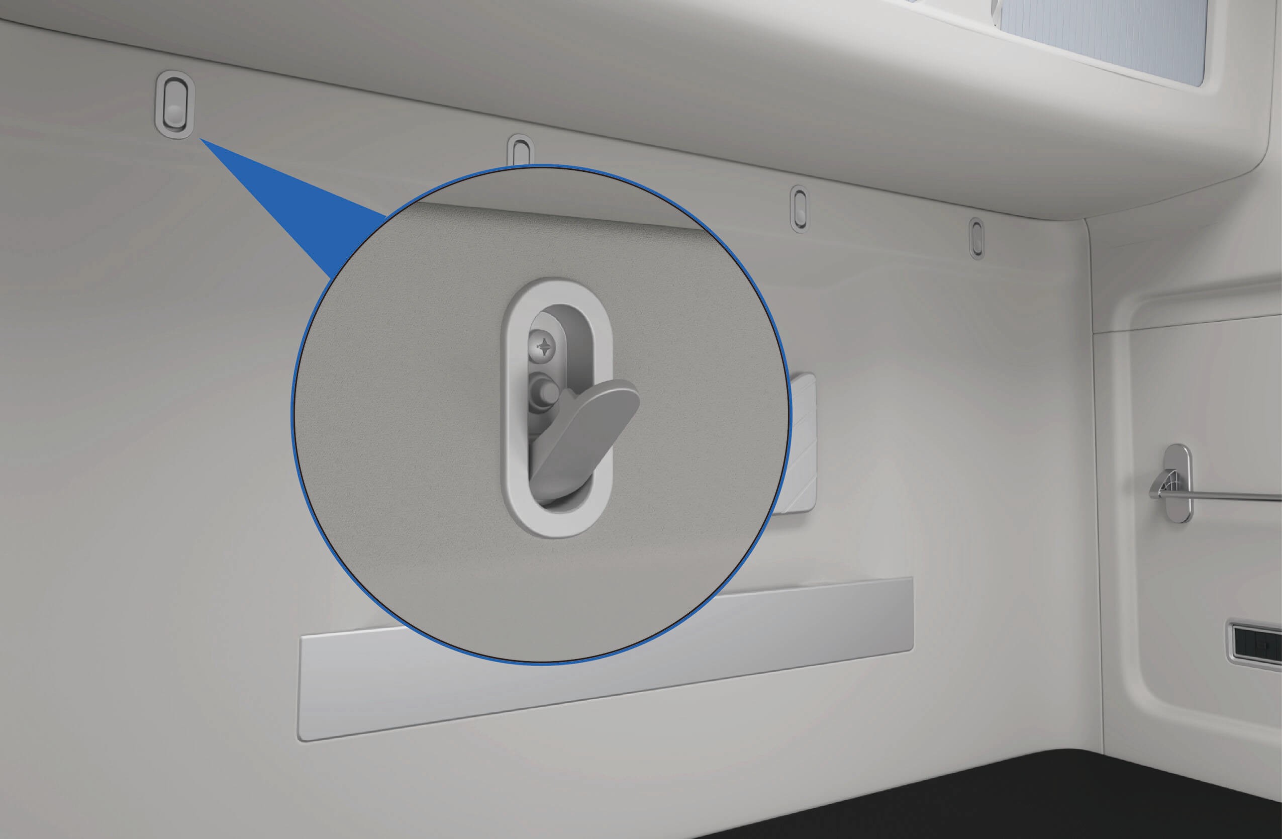
Sleeper Privacy Curtain*
↑ TopAccess to Vehicle
The sleeper area is equipped with privacy curtain rails that allow installation of privacy curtains. The curtains help provide privacy and reduce sunlight in the sleeper area.
* This feature is available on certain vehicle models only.
Operating instructions
Sleeper privacy curtain rail
The curtain rails are installed on the roof above the sleeper area. Privacy curtains can be attached to the rails as required.
Sleeper privacy curtain*
↑ TopWhen installed, the privacy curtains can be drawn across the sleeper area to provide privacy and block sunlight while resting.
Precautions
↑ TopNoticeDo not pull the privacy curtain with great effort to prevent it from falling.
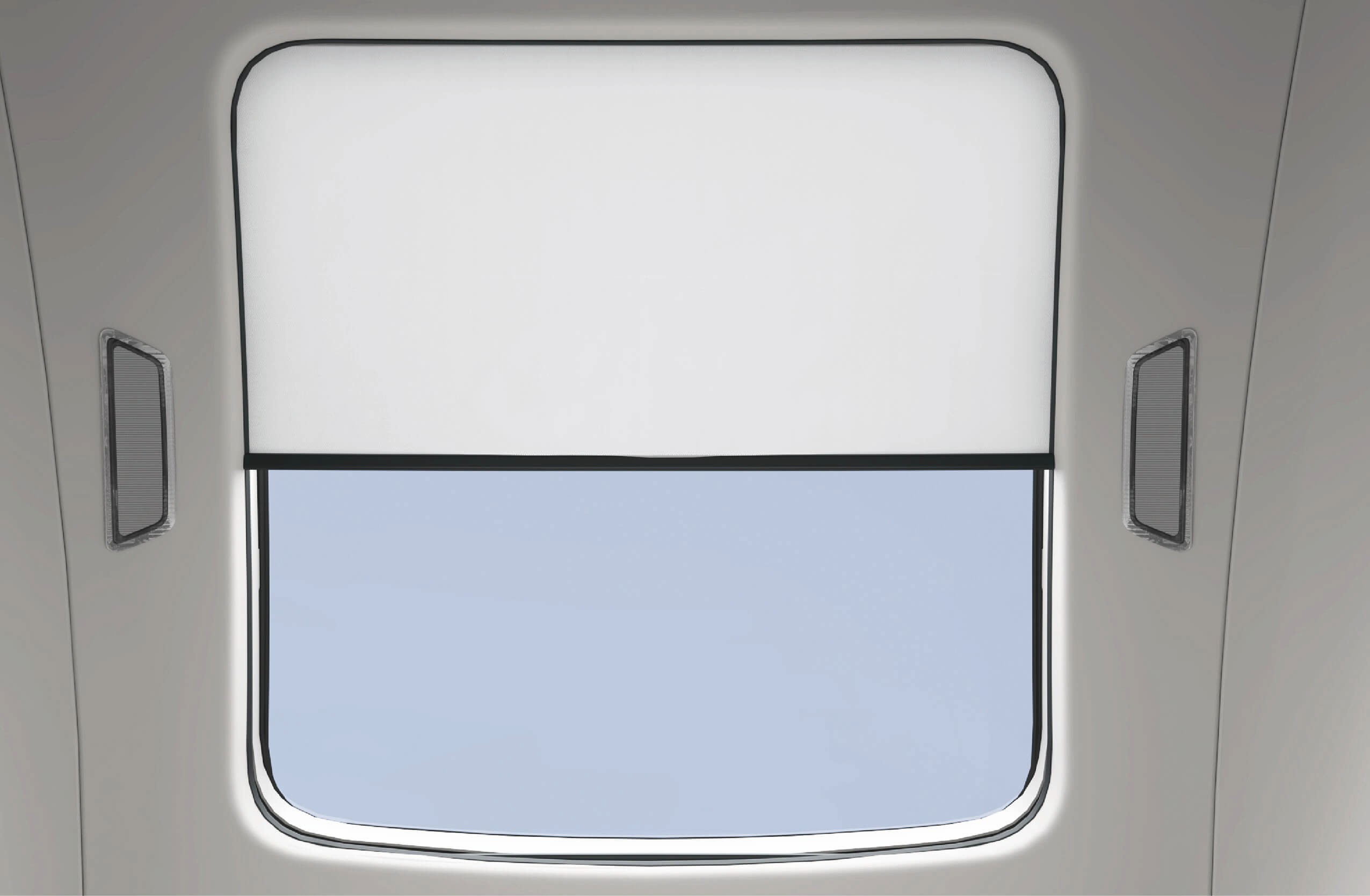
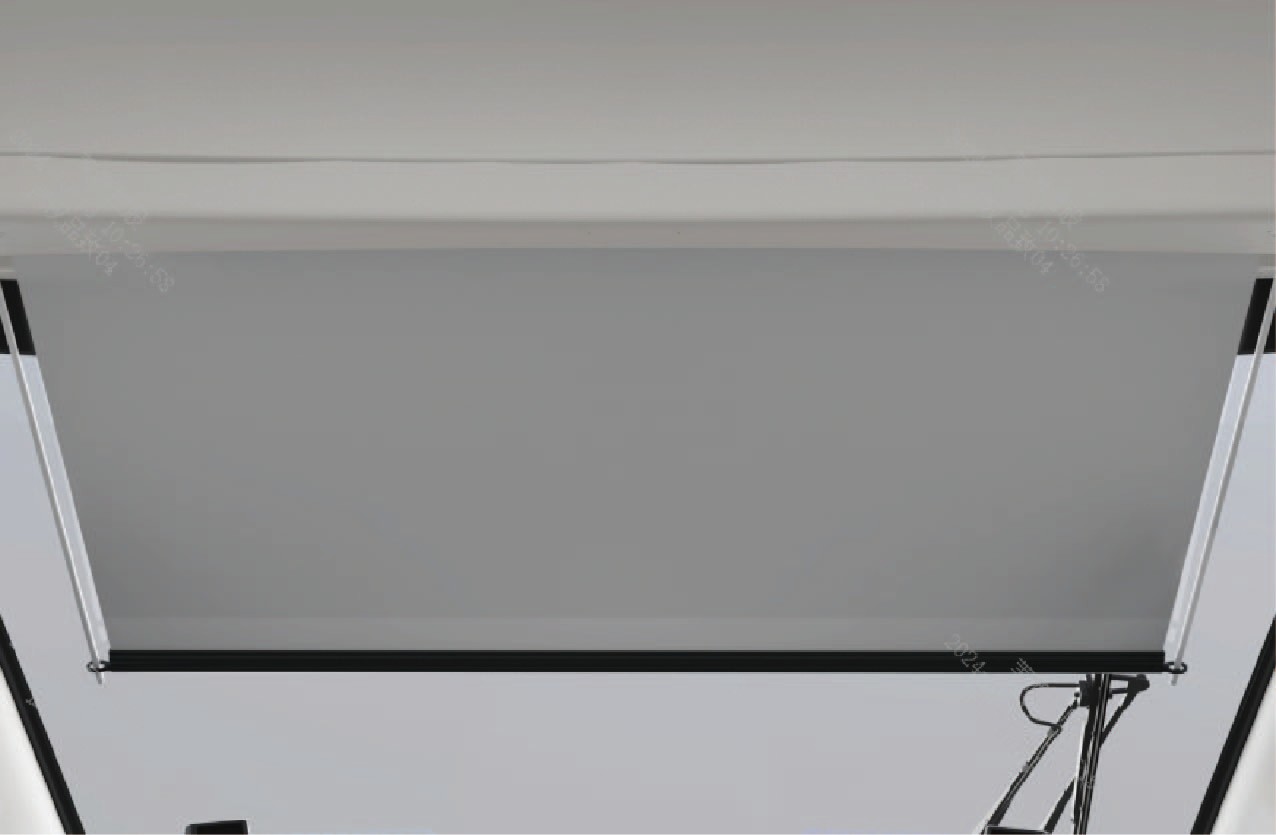
Panoramic Sunroof
↑ TopAccess to Vehicle
The vehicle is equipped with a panoramic roof and an electric sunshade. The panoramic roof is fixed and non-operable. It allows natural light into the cab and provides an outside view. The sunshade can be opened or closed to block sunlight when required.
Operating instructions
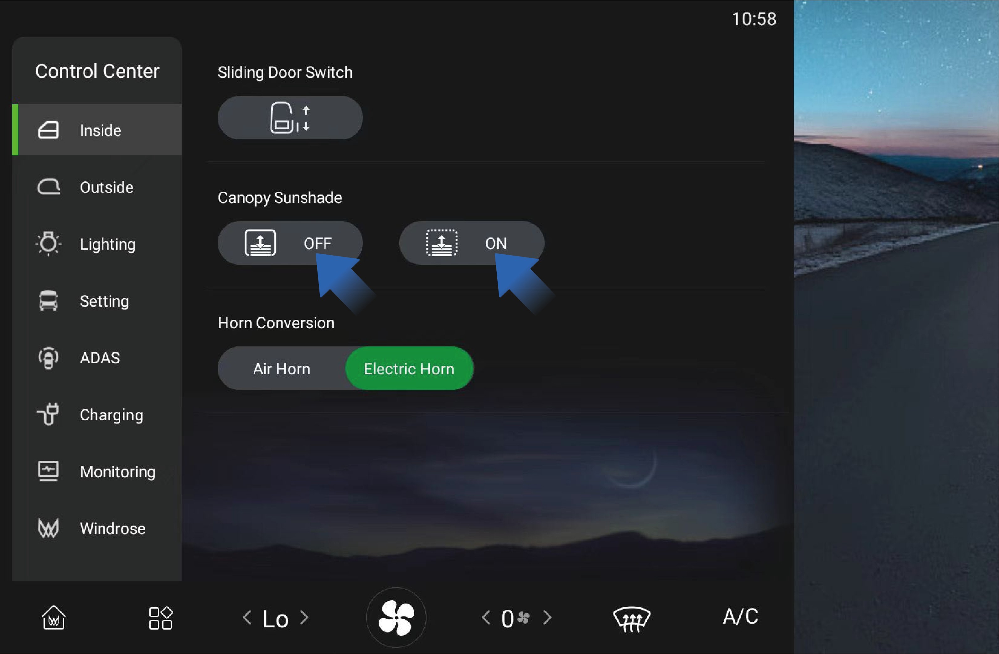
The panoramic roof sunshade can be operated through the vehicle information screen.
Select "Canopy Sunshade" in the "Inside" interface on the vehicle information screen.
Press and hold the ON/OFF button to open or close the sunshade. Release the button to stop movement.
Briefly press and release the ON/OFF button to activate automatic operation, which moves the sunshade fully open or fully closed.
Precautions
Notice
Do not manually pull the moonroof sunshade to avoid damage.
Do not scratch the moonroof glass, moonroof sunshade, or adhesive strips around the glass with sharp objects.
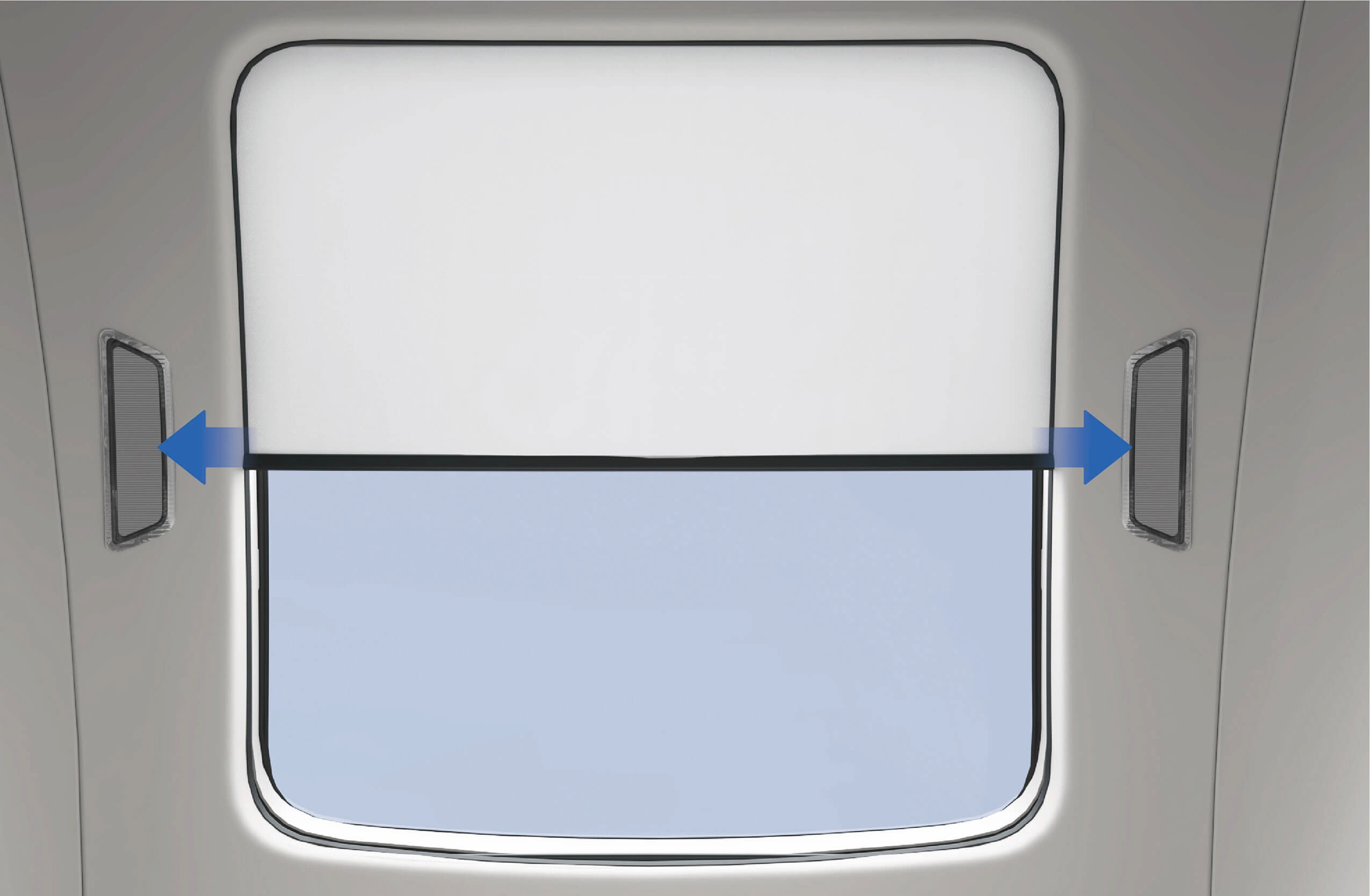
Windshield Electric Sunshade
↑ TopAccess to Vehicle
When driving toward strong sunlight, the windshield electric sunshade can be used to reduce glare and improve driving comfort.
Operating instructions
The windshield electric sunshade can be operated using the control switches located on the left side of the instrument panel.
Lower Sunshade Switch
Press and hold this switch to lower the windshield sunshade. Release the switch to stop the movement.
Raise Sunshade Switch
Press and hold this switch to raise the windshield sunshade. Release the switch to stop the movement.
Precautions
↑ TopNoticeDo not manually pull the windshield electric sunshade to avoid damage.
NoteWhen using the sunshade, make sure it does not interfere with effective vision.
Interior Sleeper
↑ TopAccess to Vehicle
In the vehicle, there are sleepers for the driver and passengers to rest.
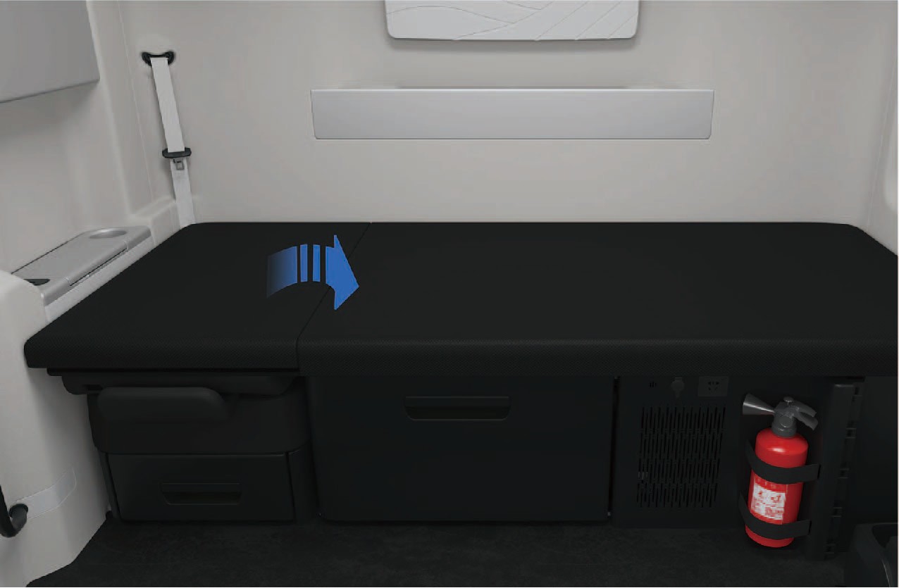
Operating instructions
The upper right cushion of the sleeper can be manually flipped and folded to the left to make room for the front passenger seat. If a height-adjustable sleeper is mounted on the right side of the vehicle, then the upper cushion of the right sleeper can be manually raised and fixed so that it can be used as a sleeper headrest available in multiple gears. To put the sleeper down, you can raise the upper cushion of the right sleeper to the highest position and then release.
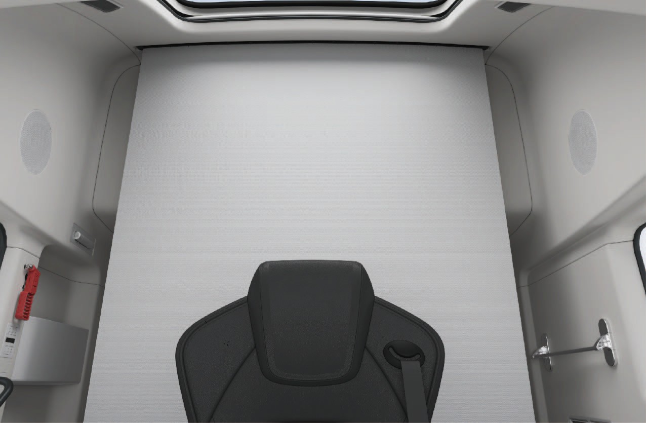
Sleeper protection net
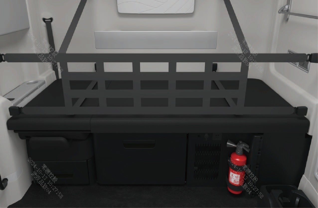
The vehicle has sleeper protection net. Before using the sleeper, unfold the sleeper protection net as shown in the figure, and then insert the 8 tongues in the left, right and rear wall of the sleeper into the 8 buckles at the left, right and rear end of the protection net respectively to lock the protection net in position.
Notice
When folding the front passenger seat or lifting the upper cushion of the sleeper, be careful not to pinch your fingers.
Please install the protection net properly before using the sleeper; If the protection net is not used, there may be a risk of passengers falling off from the sleeper, increasing the probability of injuries and deaths in accidents.
Rearview Mirror
↑ TopAccess to Vehicle
Physical rearview mirrors are mounted on the vehicle to provide the driver with a efficient driving view.
You can adjust the physical rearview mirrors by selecting "Control Center" and switching to "Outside" interface in the vehicle information screen of the instrument panel.
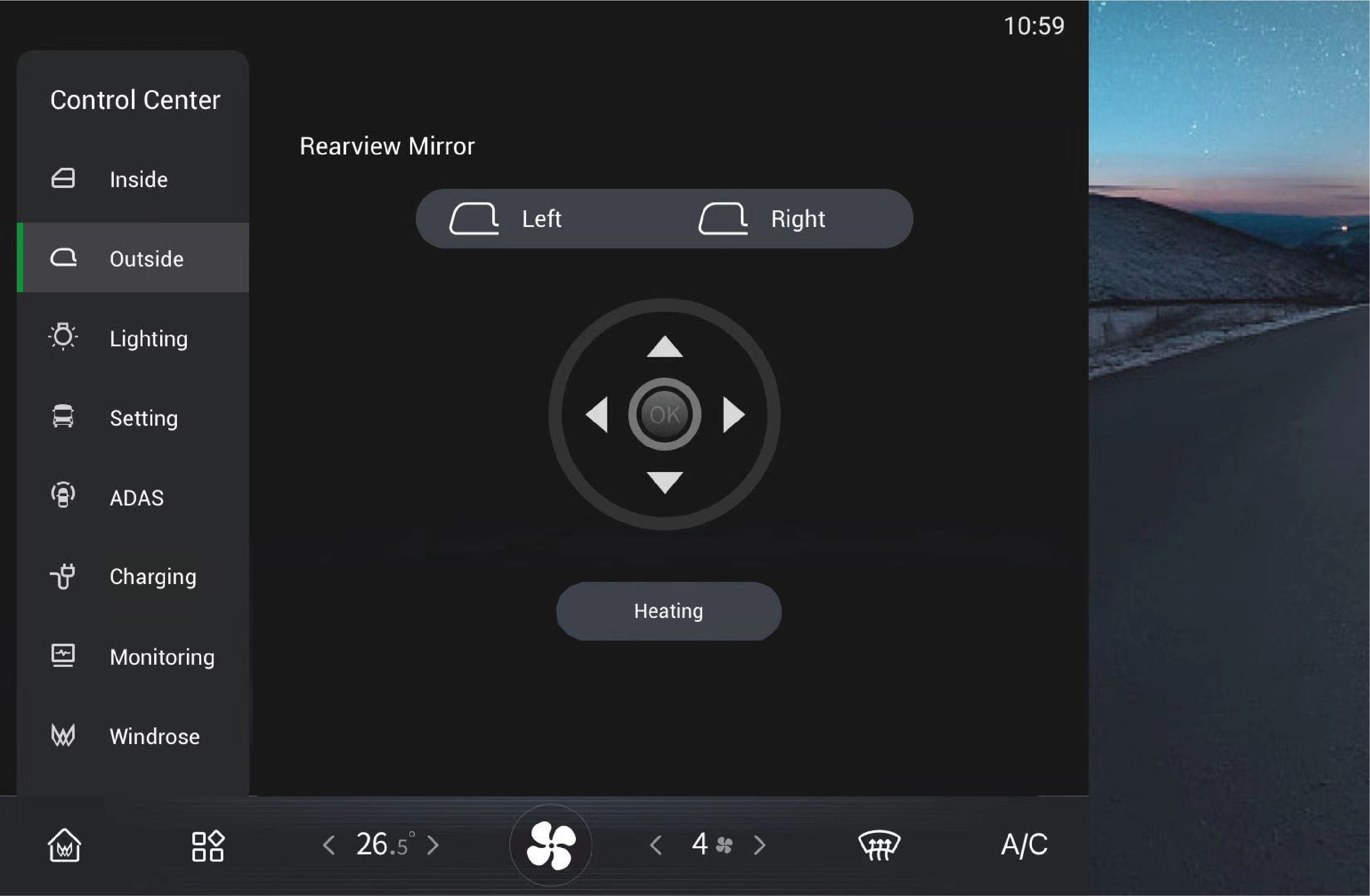
Left/right adjustment
Click to select and adjust the left/right physical rearview mirrors separately.
Rearview mirror heating
Click to select this option, and the physical rearview mirrors will
be heated to defrost and defog. Click again to turn it off, or it
will be automatically turned off after power-off.
Warning
Be sure to adjust the rearview mirrors correctly before driving, as this behavior is strictly prohibited during driving. Failure to observe this requirement will cause personal injury or death and property damage.
Do not cover the sensor. Dirt, ice and snow, if attached to the camera, may degrade its function and performance. Always pay attention to the cleanliness of the camera and its surroundings to avoid traffic accidents.
Cup Holder
↑ TopAccess to Vehicle
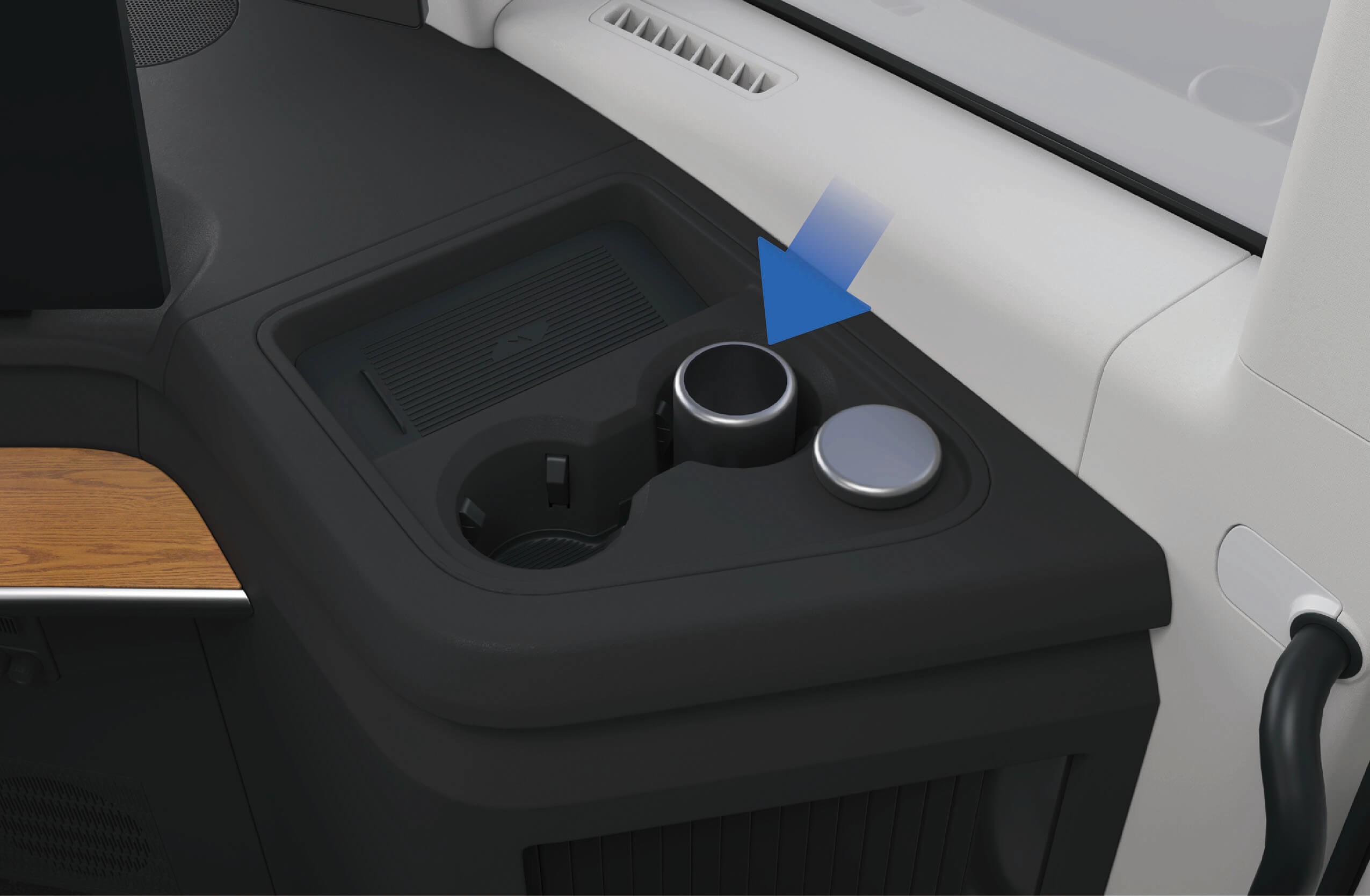
Cup holders are positioned on the left and right sides of the instrument panel separately, as well as on the armrest of the front passenger seat, so that you can place water cup or beverage container in the corresponding cup holder.
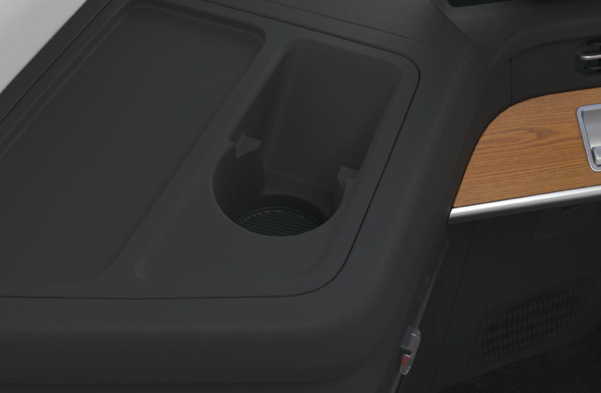
Cup holders (left)
Cup holders (right) • Cup holder on right side of front passenger seat
Precautions
WarningDo not put hot drinks in the cup holder that are not tightly covered. Otherwise they may spill when the vehicle bumps, causing personal injury or damage to vehicle components.
Note
Only beverage containers that can be sealed and properly sized can be put in the cup holder so as to prevent spilling.
Do not forcibly put an inappropriate container into the cup holder, otherwise the container or vehicle may be damaged.
Ash Tray
↑ TopAccess to Vehicle
There is an ashtray on the vehicle for the convenience of storing cigarette butts and ashes.
Operating instructions
↑ TopThe ashtray is mounted in the cup holder on the right side of the instrument panel. You can put the ashtray in other positions according to your individual needs.
Precautions
Warning
Do not smoke while driving to avoid accidents or violations of applicable regulations.
Before throwing cigarette butts into the ashtray, make sure the cigarette butts are extinguished to avoid fire accidents caused by burning cigarette butts.
When installing the ashtray, make sure it is securely installed and fastened to prevent the ashtray from shaking in the vehicle or separating from the fastening device.
↑ TopNoteWhen the ashtray is finished, be sure to cover it to avoid spilling of the cigarette butts or ashes.
Side Toolbox
↑ TopAccess to Vehicle
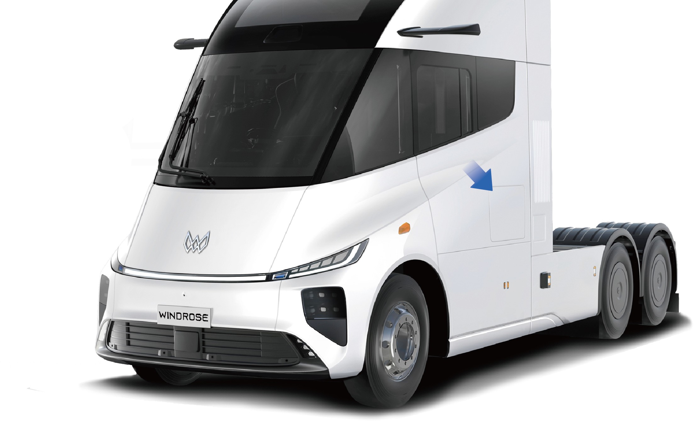
The driver's tools of the vehicle are placed in the toolbox on the left side of the vehicle for use in case of an emergency.
Operating instructions
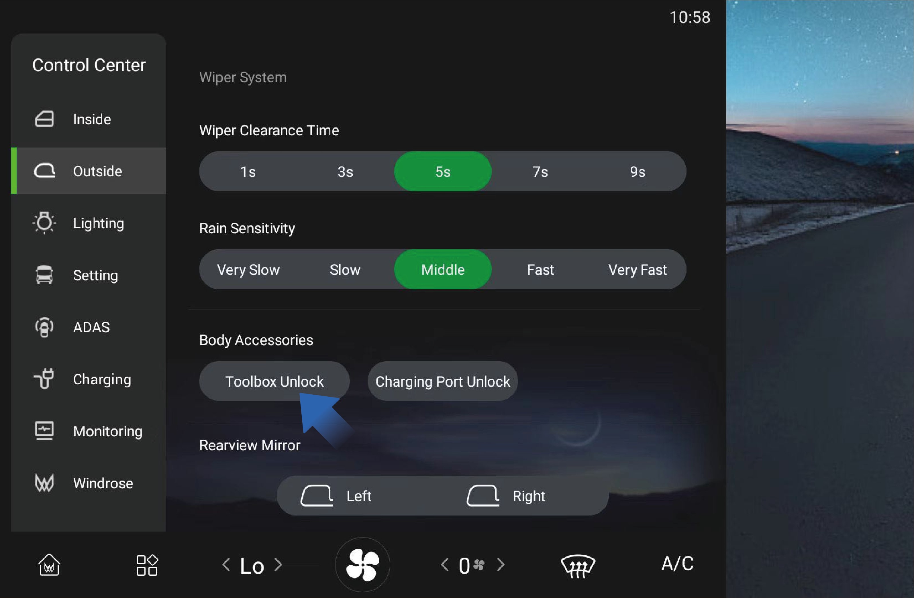
↑ TopYou can unlock the toolbox by selecting "Control Center", switching to "Outside" interface, and clicking "Toolbox Unlock" button on the vehicle information screen of the instrument panel. The toolbox is closed manually from outside the vehicle.
There is a lamp in the toolbox, and it will be automatically illuminated when the toolbox is opened and turns off automatically when the toolbox is closed.
Precautions
↑ TopWarningKeep the toolbox closed during driving to avoid accidents.
Interior Storage Device
↑ TopAccess to Vehicle
There are multiple storage devices in the vehicle for you to store items of different sizes.
Operating instructions
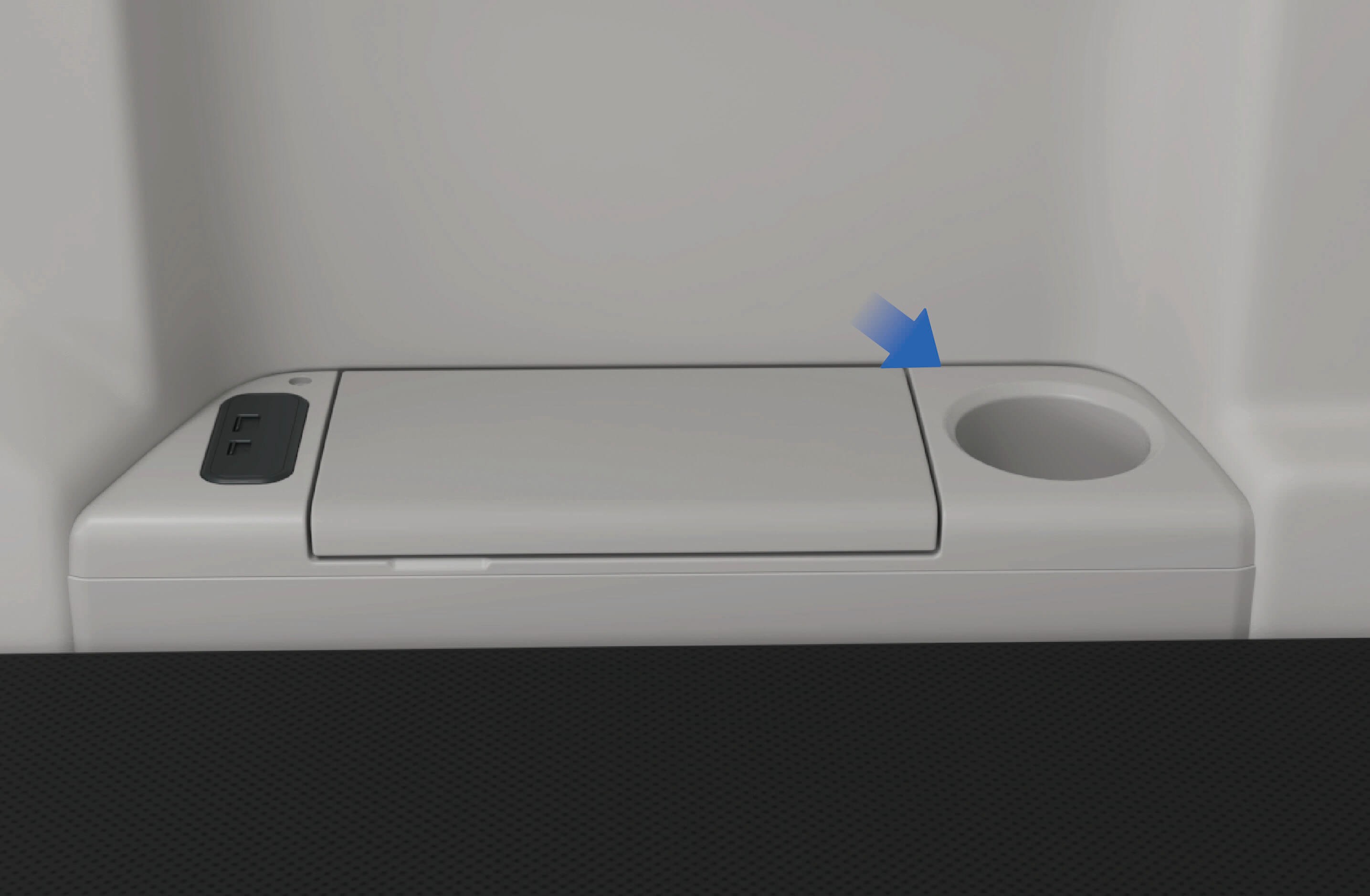
There is a storage box at the lower right of the instrument panel where you can store items.
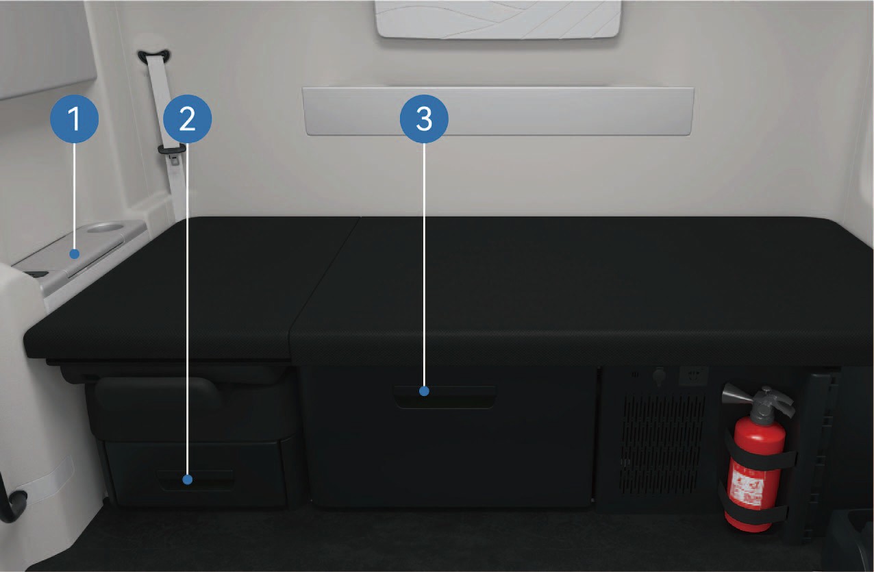
Storage box on the right side of the front passenger seat
Storage box under the front passenger seat
Storage box under sleeper
↑ TopStorage box can be found under the sleeper and the front passenger seat. You can pull it out to use it. A storage box is situated on the right side of the front passenger seat where you can store smaller items.

There is a storage box above the sleeper. The lamp in the storage box will be automatically illuminated when the storage box is opened and automatically go out when the storage box is closed. The maximum bearing capacity of the large storage box above the sleeper is 55.1 lb, and that of the small storage box is 33.1 lb.
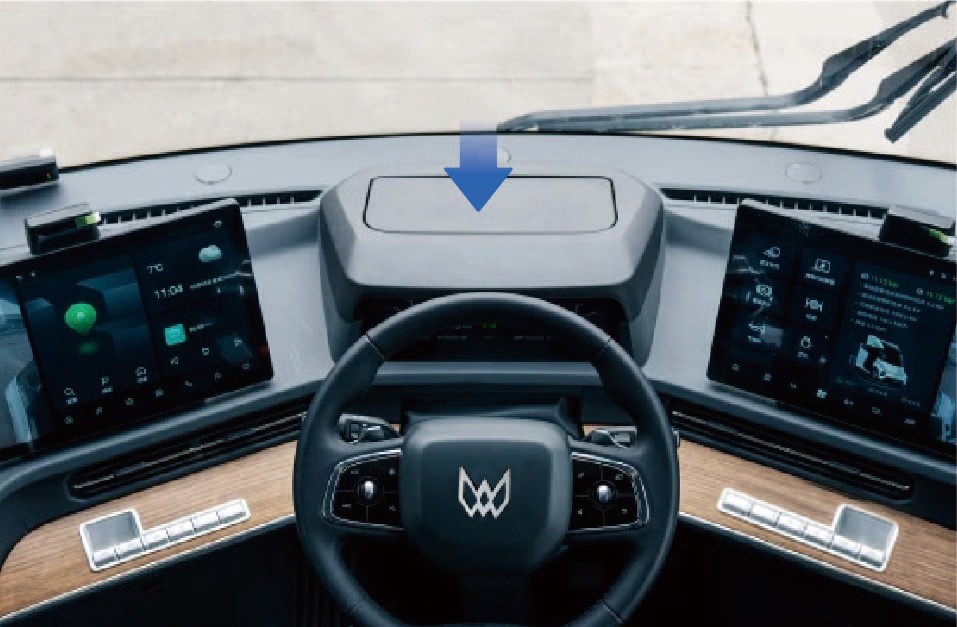
On vehicles without AR-HUD, a storage box is positioned at the location of the AR-HUD where you can place smaller items. Place small and light items rather than sharp objects in the box to avoid damage to the inner leathers of the box.
Precautions
↑ TopNoteMake sure the storage boxes are closed before driving, so as to avoid damage to items or personal injury when items fall from a height during driving.
Net Bag
↑ TopAccess to Vehicle
There is a net bag on the lower left of the vehicle to hold some smaller items.
Operating instructions
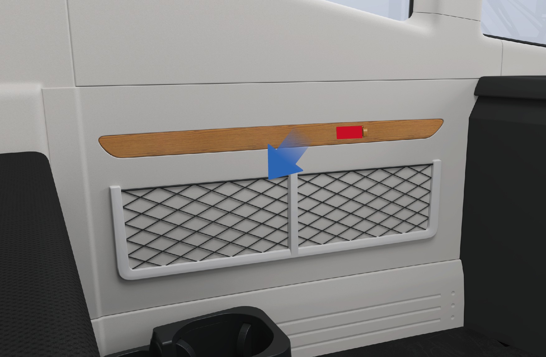
Net bag
Precautions
NoteDo not place sharp objects in the net bag to avoid damage to the net bag or injury to the driver.
Newspapers and Periodicals Device
↑ TopAccess to Vehicle
There is a newspapers and periodicals bag on the back of the driver seat, which can be used to store small items such as newspapers and maps.
Next to the sleeper, there is a newspapers and periodicals device where you can store newspapers, periodicals and other items.
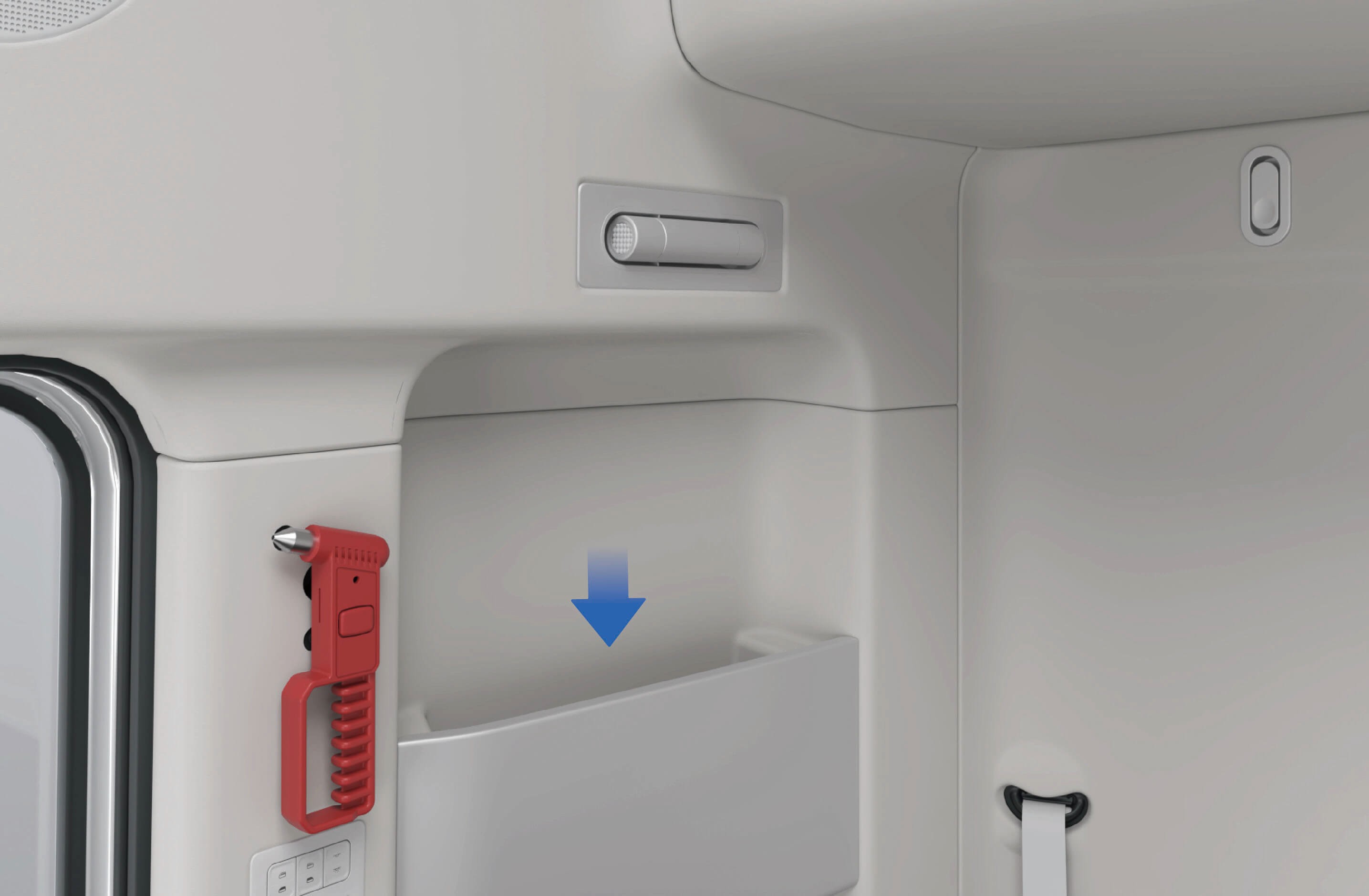
Newspapers and periodicals bag above sleeper • Newspapers and periodicals bag on the right side of the
sleeper
Precautions
↑ TopNoteThe newspapers and periodicals device affixed to the sleeper can only hold items such as newspapers and periodicals. Small items, if placed in the bag, cannot be taken out from the bag.
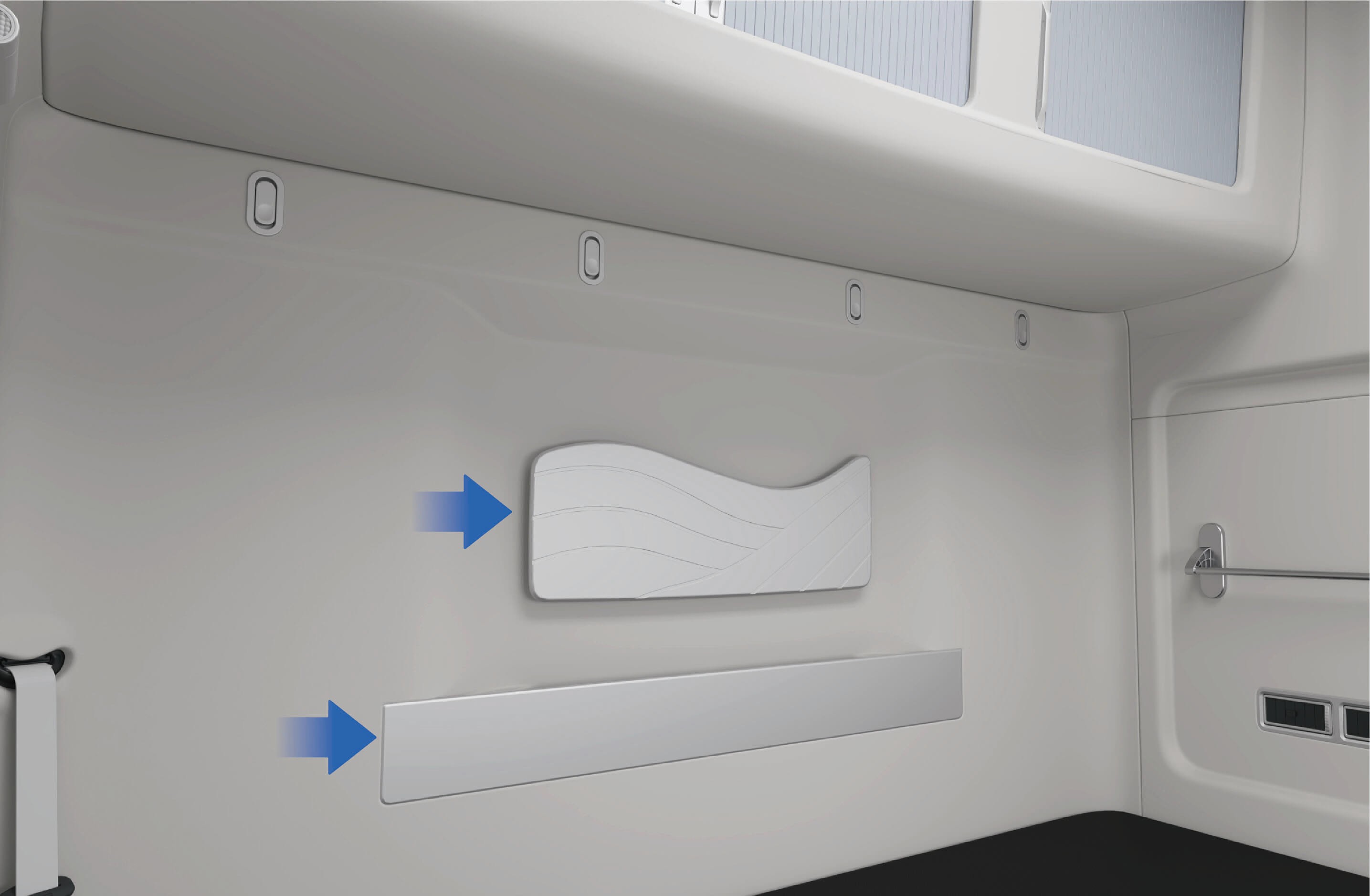
Coat Hook
↑ TopAccess to Vehicle
There is a coat hook above the sleeper that is used for hanging clothes up.
Operating instructions
Coat hook
Precautions
NoteThe coat hook can only hold light clothes or hats, etc. Do not hang heavy objects.
Hanging Device
↑ TopAccess to Vehicle
There is a hanging device on the side of the sleeper that can be used to hang towels or small clothes.
Operating instructions
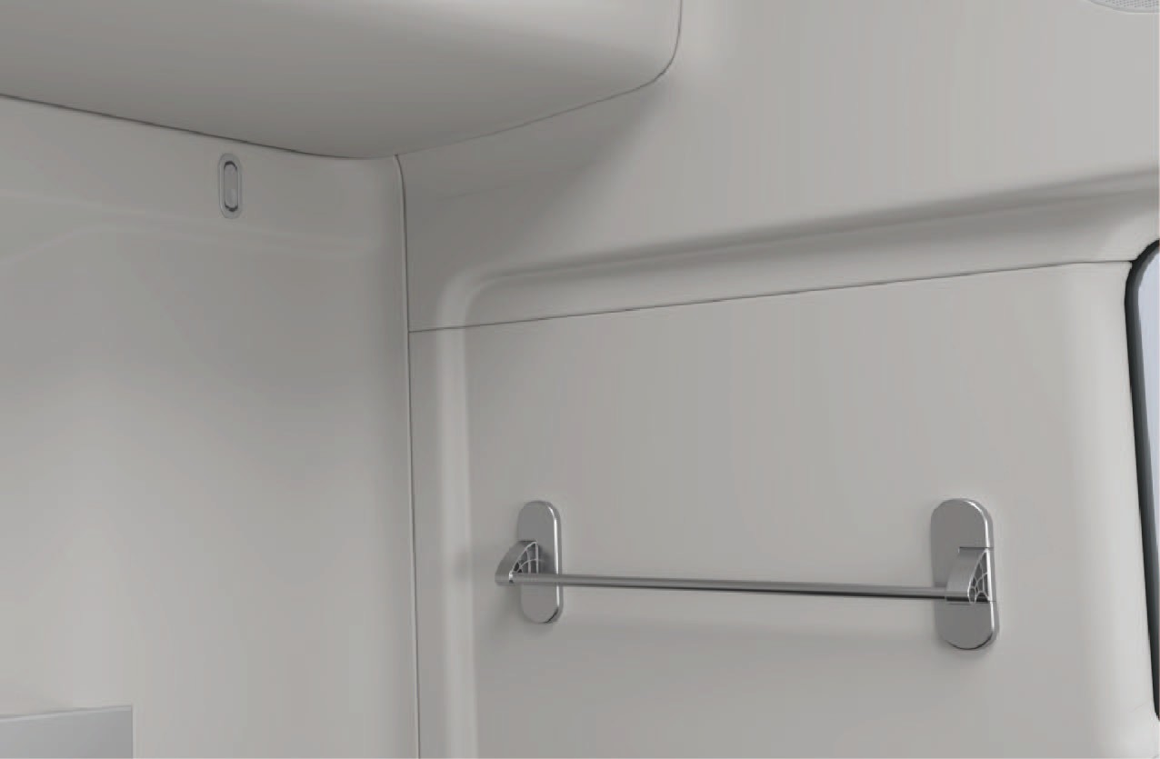
Hanging device
Precautions
NoteThe hanging device can only be used to hang dry towels or small clothes. Do not hang heavy objects to avoid damaging the hanging device and causing accidents.
USB Charging
↑ TopAccess to Vehicle
The vehicle is provided with USB ports, respectively located on the left instrument panel and the armrest of the front passenger seat. The USB ports can be used to charge mobile phone with a charging power of 15W. Both type-C and type-A ports are supported.
Operating instructions
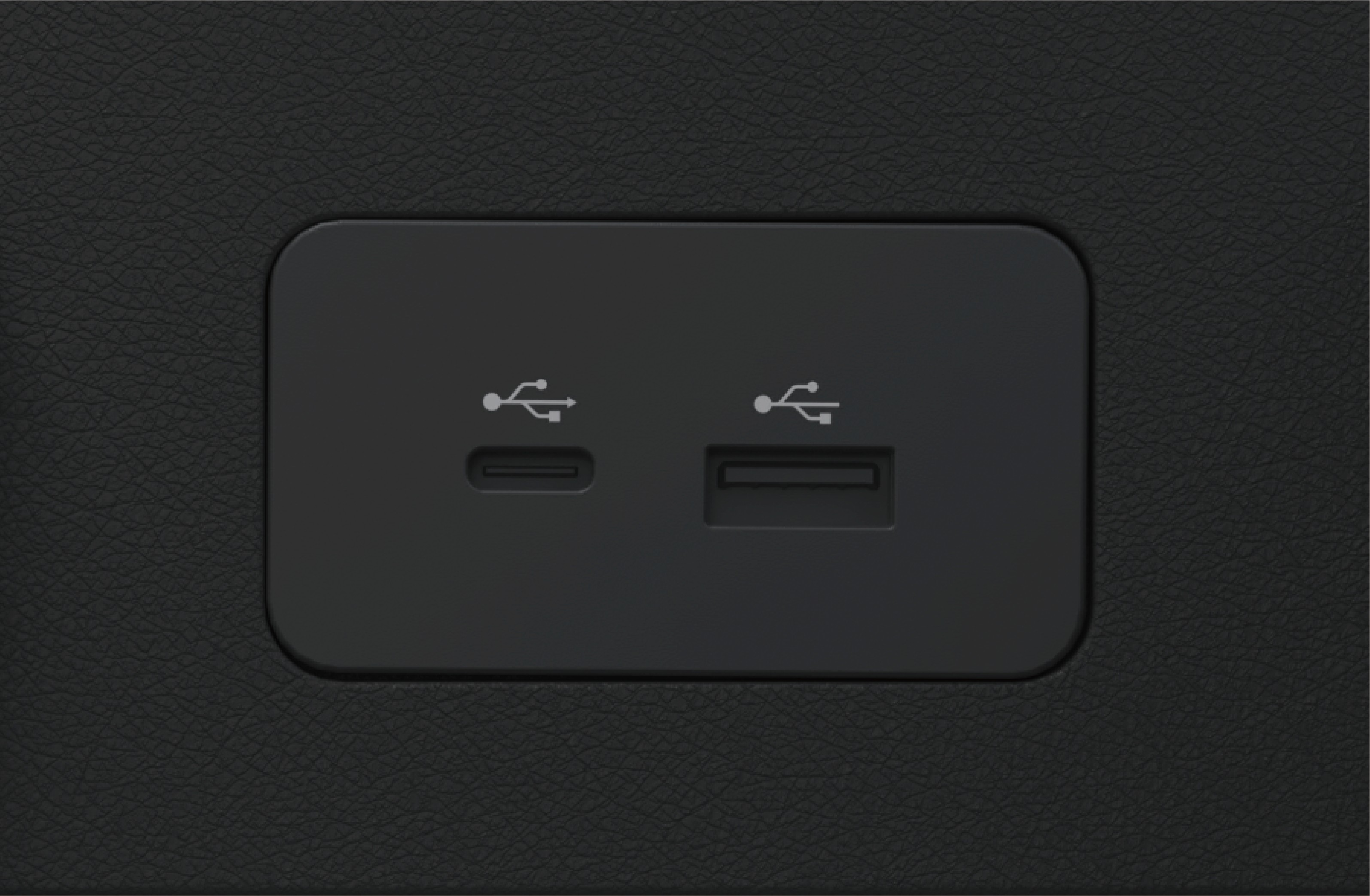
Instrument panel left USB port
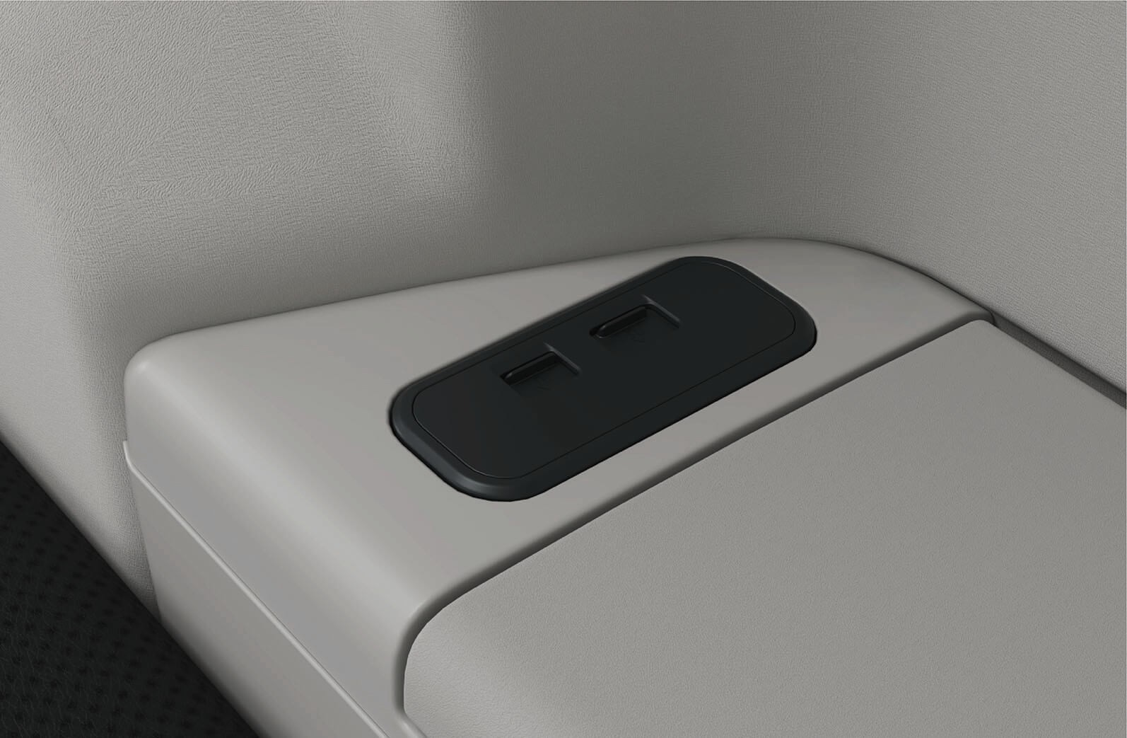
USB port at front passenger seat armrest
Precautions
↑ TopWarningNever spill liquid at the port.
NoticeConnected devices may get hot during charging. Make sure that the hot devices will not endanger personnel safety or cause property damages.
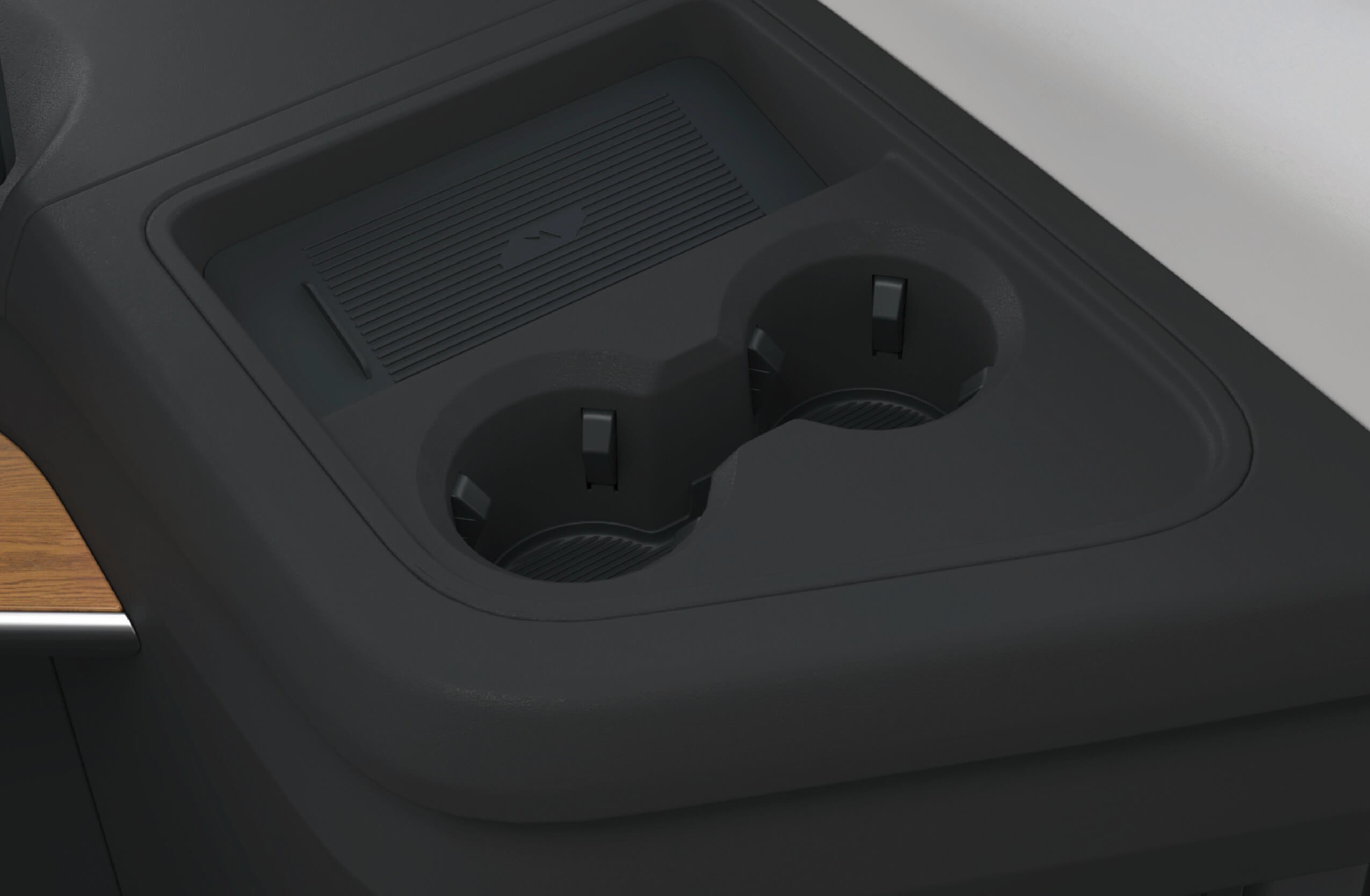
Phone Wireless Charging
↑ TopThe right instrument panel is equipped with a wireless charging device, which can be used to charge mobile phones wirelessly with a charging power of 15W.
Precautions
↑ TopWarningDo not place objects containing metal components in the wireless charging induction area together with the mobile phone, otherwise the objects containing metal components may be heated or damaged, causing a safety accident.
When charging, please place the mobile phone face up within the
wireless charging induction area.
Operating instructions
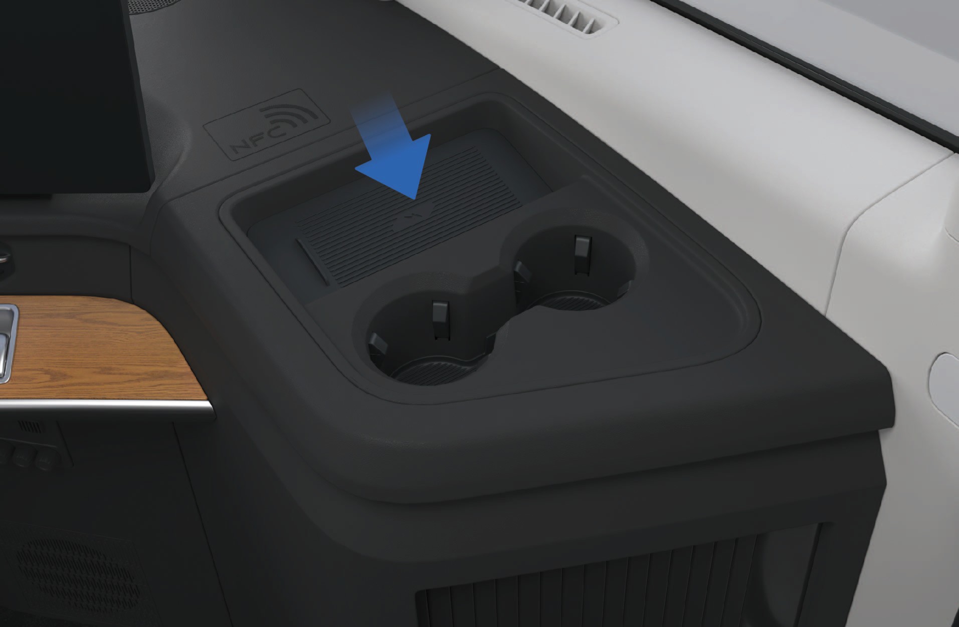
Phone wireless charging area
Notice
- Before activating the wireless charging function of the phone, ensure that the card key, credit card or other magnetic objects are kept away from the charging area.
Do not put the unattended mobile phone in the vehicle for charging, so as to avoid the safety risk.
Do not spill liquids at the wireless charging area to avoid damage to the electronic components.
Please do not place heavy objects in the charging area to avoid damaging the wireless charging module of the mobile phone.
Note
It is normal for the mobile phone to experience an increase in temperature during charging.
When the mobile phone is hot, the vehicle may stop charging to protect the battery of the mobile phone and the charging will not be resumed until the mobile phone cools down.
The wireless charging function only supports mobile phones, earphones, stereos and other devices that meet the wireless charging protocol.
When using the wireless charging function, please place the device in the center of the charging area to prevent the device from failing to be charged or being charged inefficiently.
Only 1 mobile phone can be charged at a time.
If the phone case is made of special material (such as a phone case with a metal bracket/metal magnet) or is too thick, it may cause charging failure.
When the vehicle is driving on a bumpy road, the wireless charging of the mobile phone may be intermittently stopped.
If the mobile phone cannot be charged properly, always make sure that the mobile phone is placed in the wireless charging area without foreign objects, or wait for the wireless charging
↑ Topinduction area to cool down before another try. If charging is
still impossible, contact a Windrose authorized service center in time.
Power Outlet
↑ TopAccess to Vehicle
The lower left corner of the sleeper is equipped with 2 DC power supplies, configured as:
Rated voltage: 24V
Maximum current: 15A Rated voltage: 12V
Maximum current: 10A
The lower left corner of the sleeper is equipped with one 120V inverter and socket, configured as follows:
Rated power: 1000W
Rated voltage: AC120V
Output frequency: 60Hz ± 0.5Hz
Operating instructions
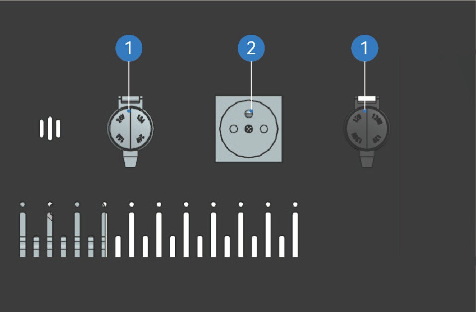
DC power supply
AC power supply
24V Trailer Power Outlet: Maximum Safe Operating Power: 2 kW
Precautions
↑ TopNoticeThe 120V inverter can only be used when the vehicle is connected with high voltage. If the vehicle is powered off, only the 12V power or 24V power supply is available.
Ceiling Lamp
Interior Lighting
The ceiling lamp can be turned on and off in two ways.
Ceiling lamp on switch
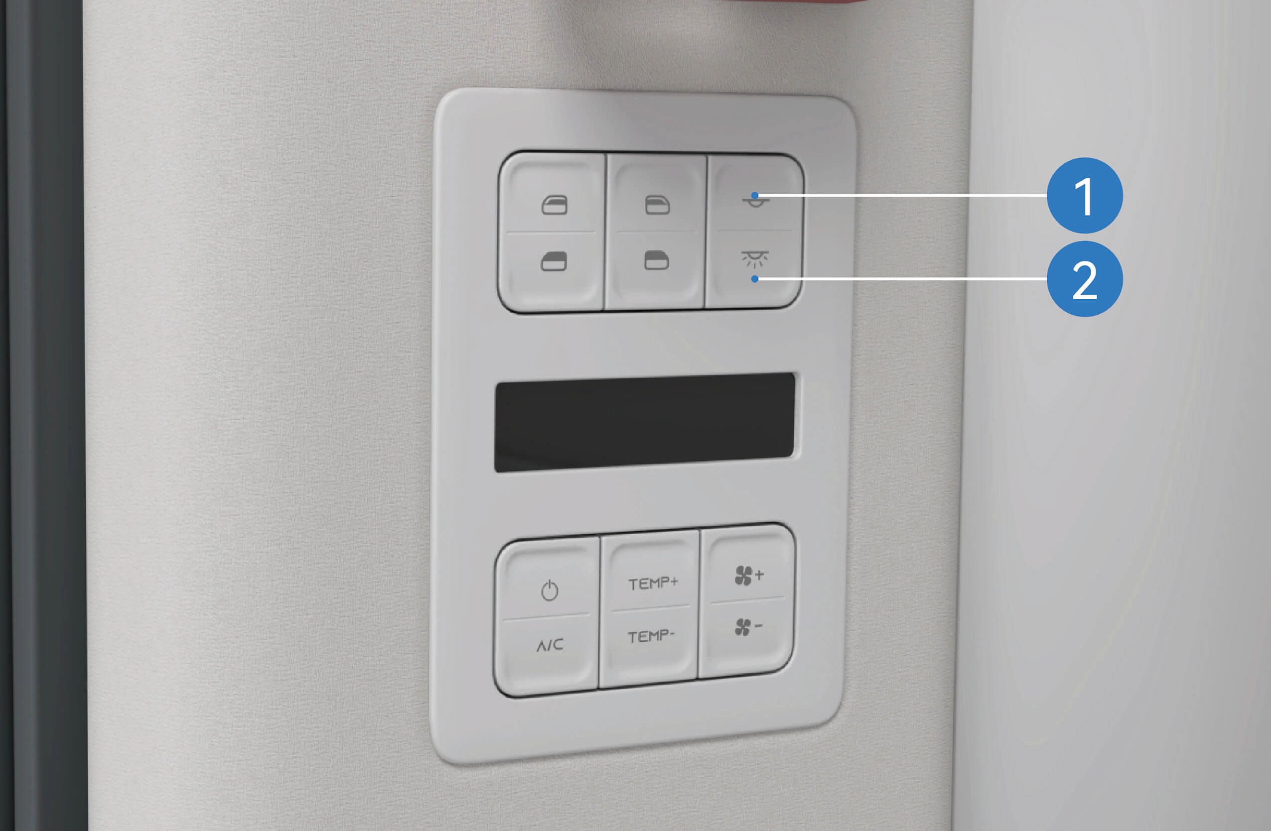 Ceiling lamp/interior lamp off switch
Press the upper ceiling lamp on switch to turn on the ceiling lamp; Press and release the lower ceiling lamp/interior lamp off switch to turn off the ceiling lamp, and press and hold the upper ceiling lamp/interior lamp off switch to turn off the ceiling lamp.
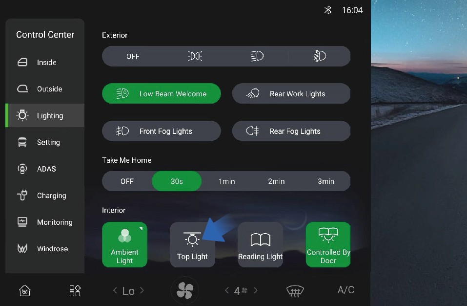
In addition, you can turn on/off the ceiling lamp by selecting "Control Center", switching to "Lighting" interface and clicking "Top Light" button on the vehicle information screen of the instrument panel.
ON/OFF with door opening/closing function

You can activate/deactivate the ON/OFF with door opening/ closing function by selecting "Control Center", switching to "Lighting" interface, and clicking "Controlled By Door" button on the vehicle information screen of the instrument panel. When this function is activated, the ceiling lamp will be illuminated or go out when the door opens or closes.
Precautions
↑ TopWarningWhen driving at night, do not use front interior lamps. Bright lights inside the vehicle can reduce the visibility when driving at night, probably causing a collision.
Operating instructions
Courtesy Lamp
↑ TopThe vehicle has welcome light function.
Interior Lighting
You can activate/deactivate low beam welcome function by selecting "Control Center", switching to "Lighting" interface, and clicking "Low Beam Welcome" button on the vehicle information screen of the instrument panel.
Follow-me-home
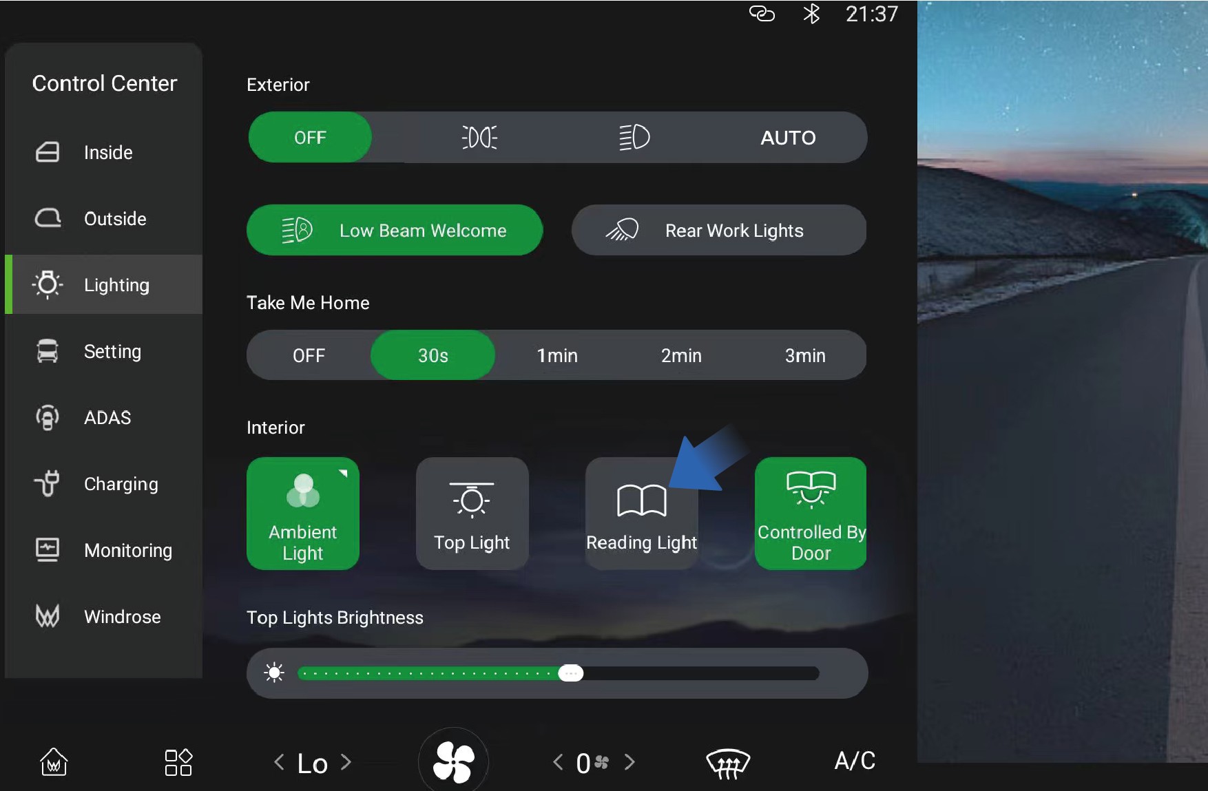
Reading Lamp
↑ Top
Interior Lighting
The cab and the sleeper are equipped with reading lamps that can be turned on when you need reading lighting.
Operating instructions
↑ TopCab reading lamp
You can activate/deactivate the follow-me-home function by selecting "Control Center" and switching to "Lighting" interface on the vehicle information screen of the instrument panel.
Precautions
NoteYou can set the duration of follow-me-home as needed.
Cab reading lamp
You can activate/deactivate the reading lamp by selecting "Control Center", switching to "Lighting" interface, and clicking "Reading Light" button on the vehicle information screen.
Sleeper reading lamp
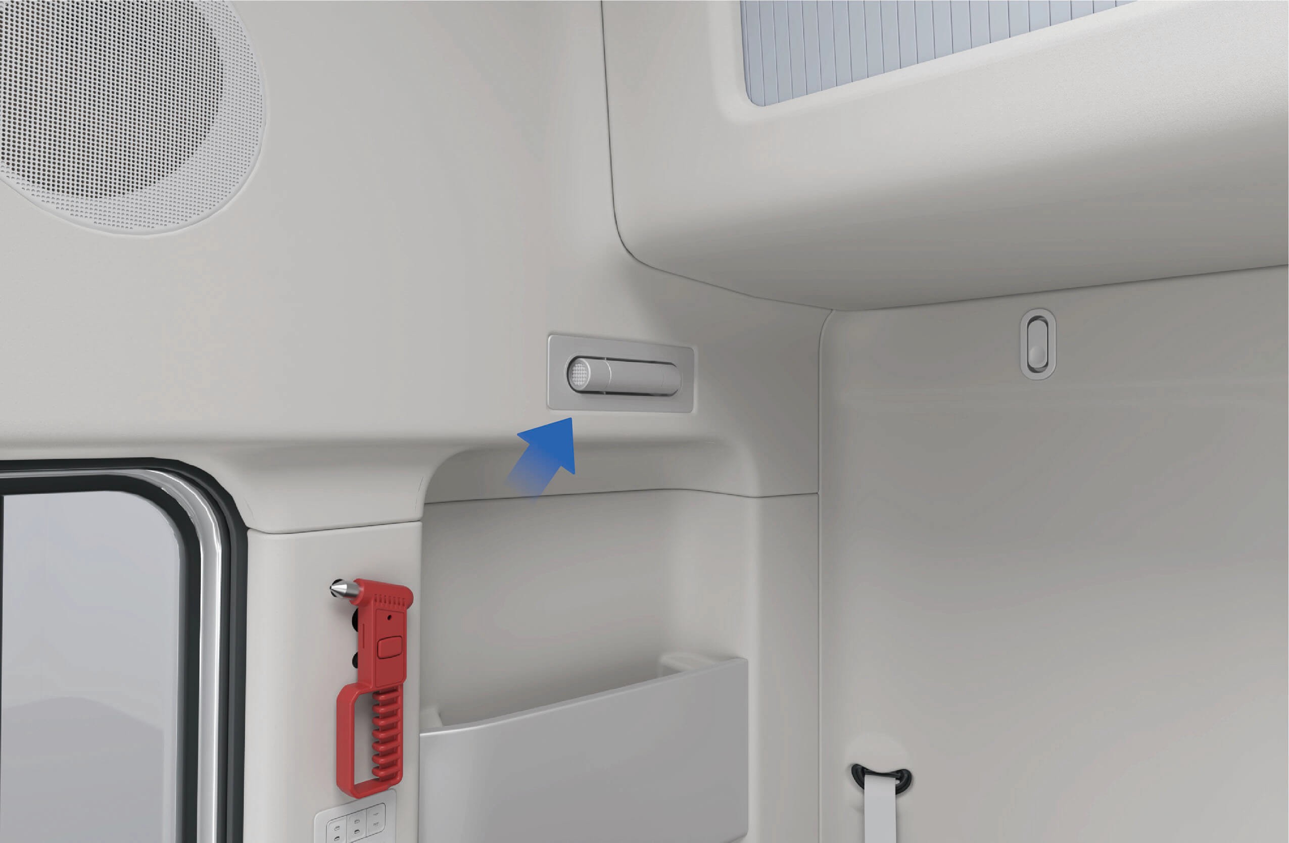
↑ TopThere is a reading lamp above the sleeper, which can be pulled out by pressing the front end to turn on the switch. This lamp will be automatically illuminated when it is pulled out, and it is allowed to adjust the lamp angle according to your needs. Reset the reading lamp, and it will be turned off automatically.
Precautions
↑ TopNoteWhen the ambient light is weak, do not turn on the reading lamps
Ambient Lamp
↑ Top
Interior Lighting
while driving. Otherwise the windshield may have reflections,
resulting in unclear visibility of the road ahead and further a safety accident.
The vehicle has ambient lamps that can switch among a variety of colors and realize musical rhythm.
Operating instructions
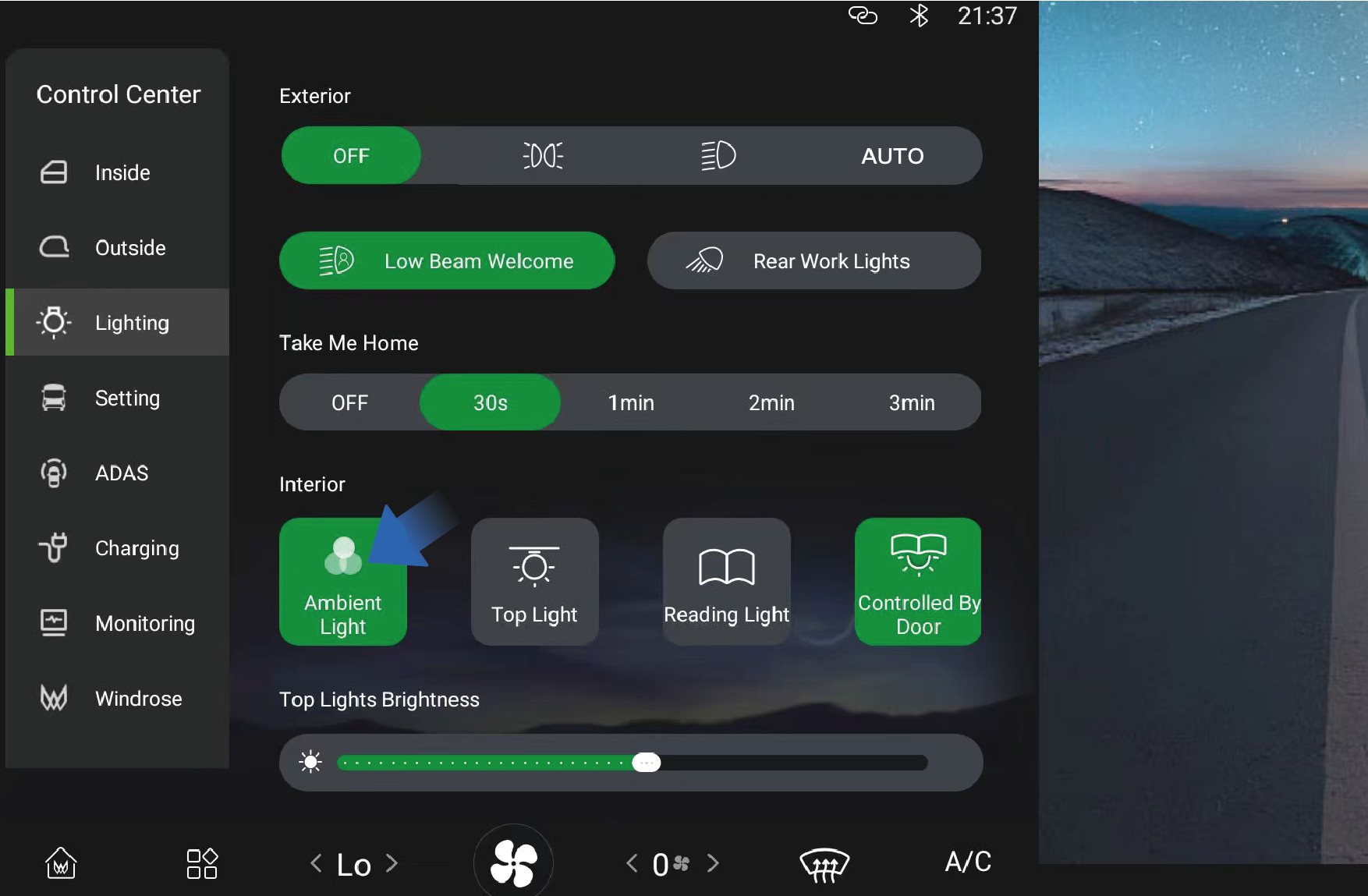
↑ TopYou can adjust the ambient lamp by selecting "Control Center", switching to "Lighting" interface and selecting "Ambient Light" button on the vehicle information screen of the instrument panel.
You can adjust the ambient lamp by yourself according to your needs and preferences.
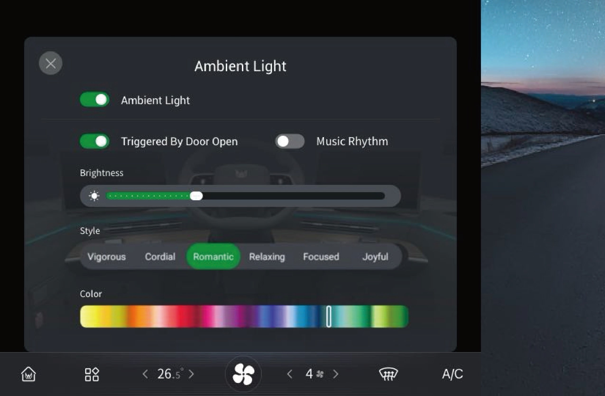
Precautions
↑ TopNoteWhen using ambient lamps, make sure the light color does not interfere with the driver's vision and ensure driving safety.
A/C Control System
↑ TopA/C on Vehicle
You can set and control the A/C through the A/C interface in the vehicle information screen or through the A/C control panel on the upper right of the sleeper in the vehicle.
Front A/C system interface
In the A/C interface of the vehicle information screen, you can set the air volume, temperature or air direction of the front and rear A/C by switching between the front and rear A/C interface.
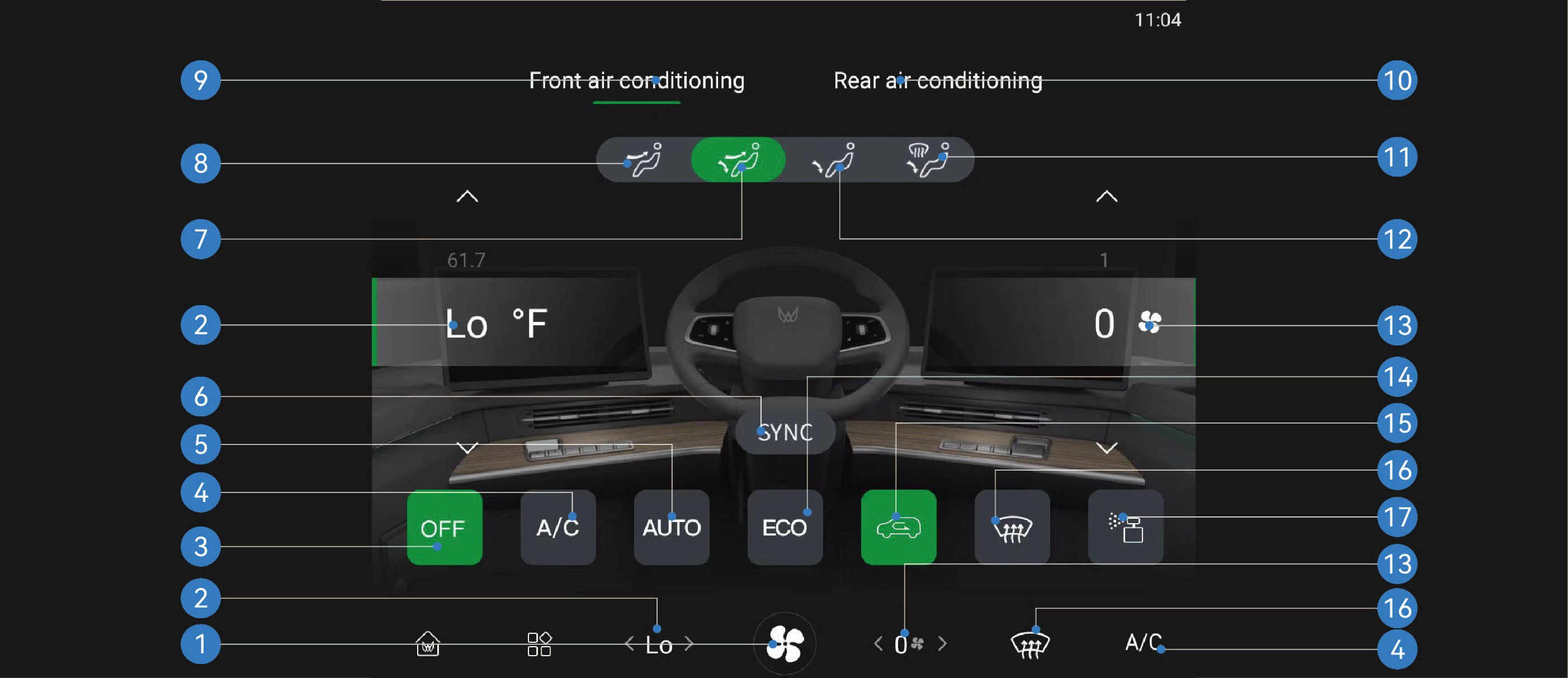
Enter A/C interface 6. Vehicle A/C temperature synchronization switch
11. Footwell and defrost mode
Windshield defrosting/ defogging switch
Front A/C temperature 7. Face and footwell mode 12. Footwell mode 17. Fragrance interface*
Front A/C OFF switch 8. Face blowing mode 13. Front A/C air volume
Compressor switch 9. Front A/C interface 14. ECO mode switch
Auto mode switch 10. Rear A/C interface 15. Internal/external circulation
switch
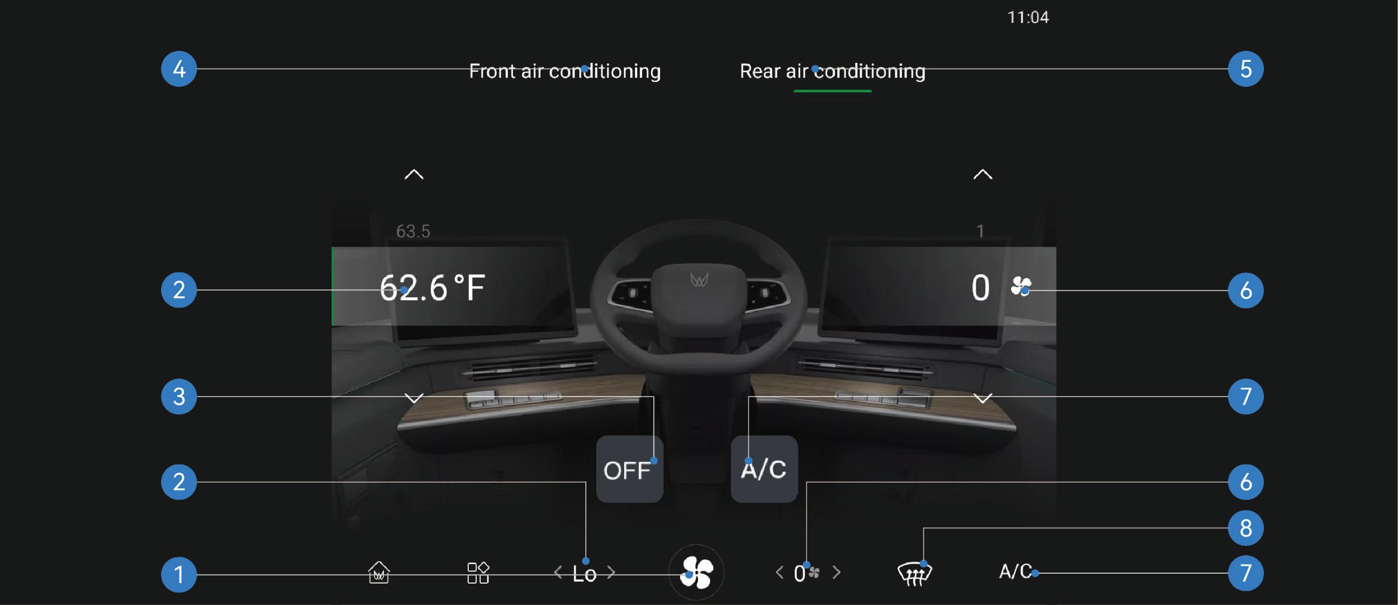
Rear A/C system interface
|
|
|
|
|---|---|---|---|
|
|
|
|
Operating instructions
|
|
|
|---|---|---|
|
|
|
|
|
|
|
|
|
|
|
|
|
|
|
|
|


|
|
|
|---|---|---|
|
|
|
|
|
|
|
|
|
|
|
|
|
|


|
|
|
|---|---|---|
|
|
|
|
|


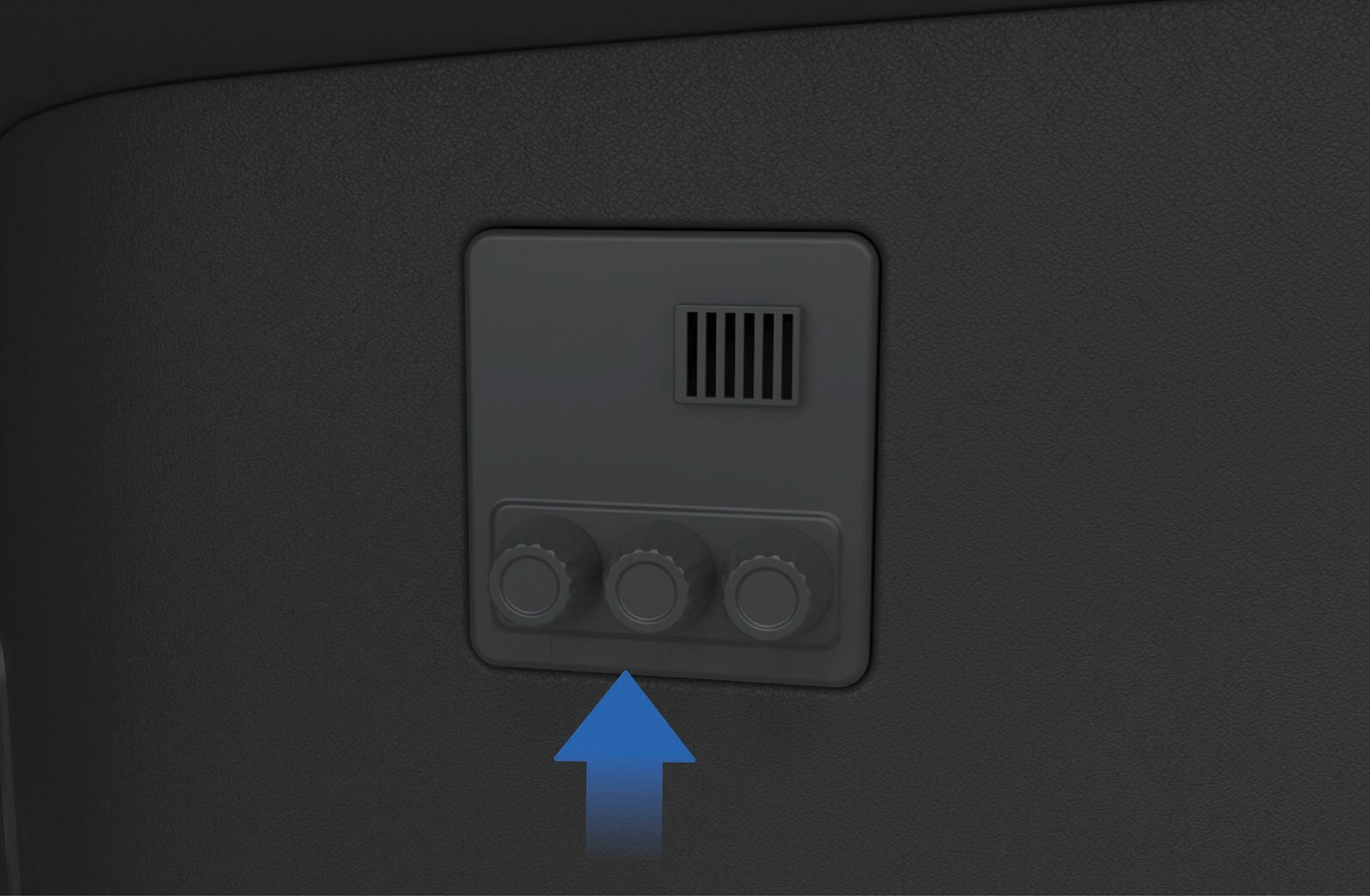
A/C control panel
The A/C control panel only controls the corresponding functions of the rear A/C.
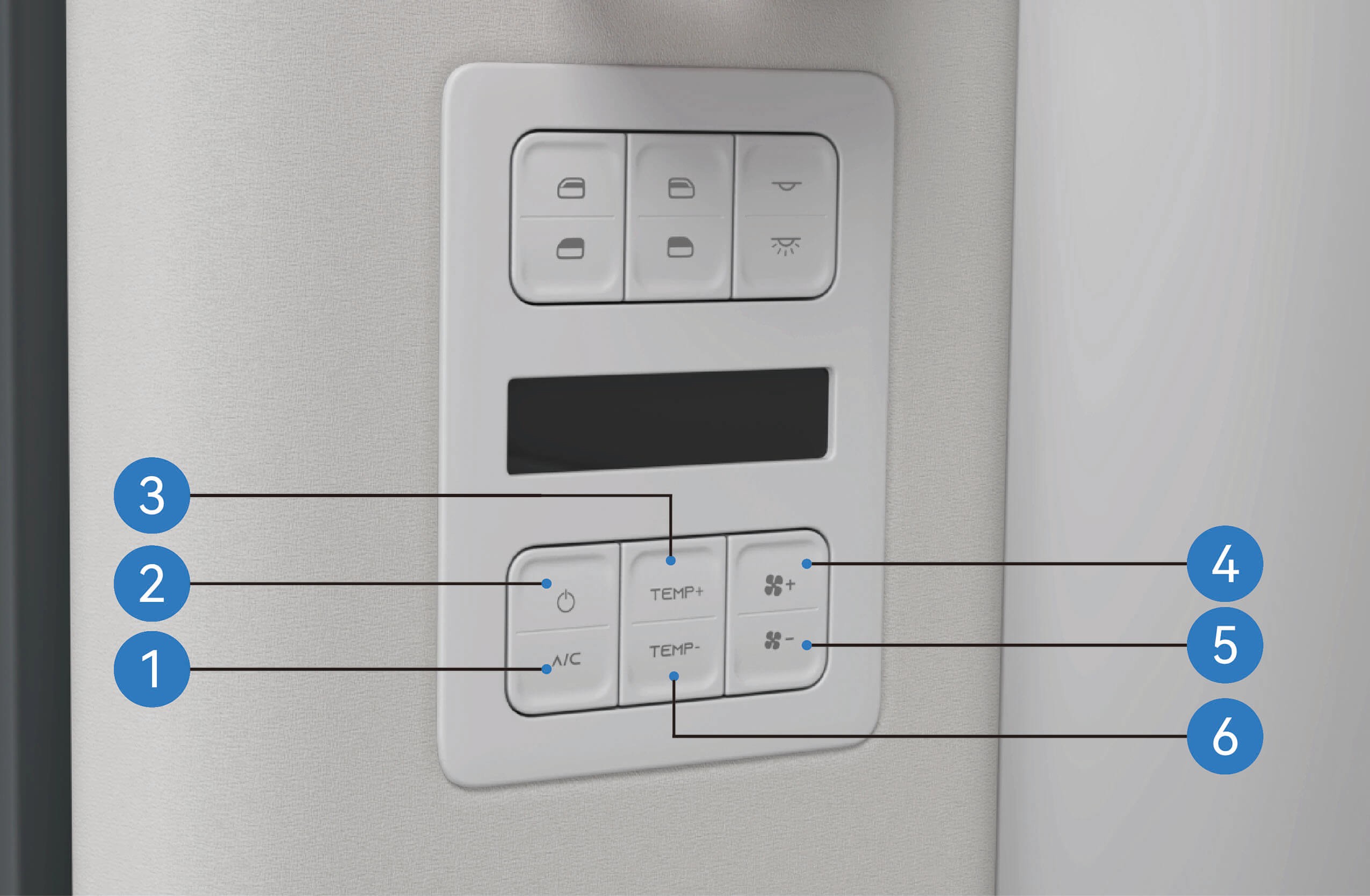
Rear compressor switch button
Rear A/C switch
Rear A/C temperature increase
Rear A/C volume+
Rear A/C volume-
Rear A/C temperature decrease
Precautions
Warning
Before driving, make sure that all windows are free of ice, snow or fog, otherwise your vision will be obstructed, thus resulting in a traffic accident.
Do not turn on the internal circulation function for a long time, which may cause the air in the vehicle to be not fresh and the windows to fog.
Note
Turning off the compressor switch cannot turn off the A/C system, and the heating system may still be working.
When you turn on the A/C system for the first time in very humid environment, it is normal for the windshield to fog up slightly.
If the A/C system works aloud, you can manually downshift the air volume of the A/C.
A slight sound like water running or a swishing sound can be
heard when the A/C system is working or turned off. This
sound is made by the refrigerant during normal operation of the A/C system, which is normal.
When you feel that the air inside the vehicle is musty and stale, you can turn on the external circulation function to introduce the outside air into the vehicle to keep the air in the vehicle fresh.
A/C Vent Adjustment
↑ TopA/C on Vehicle
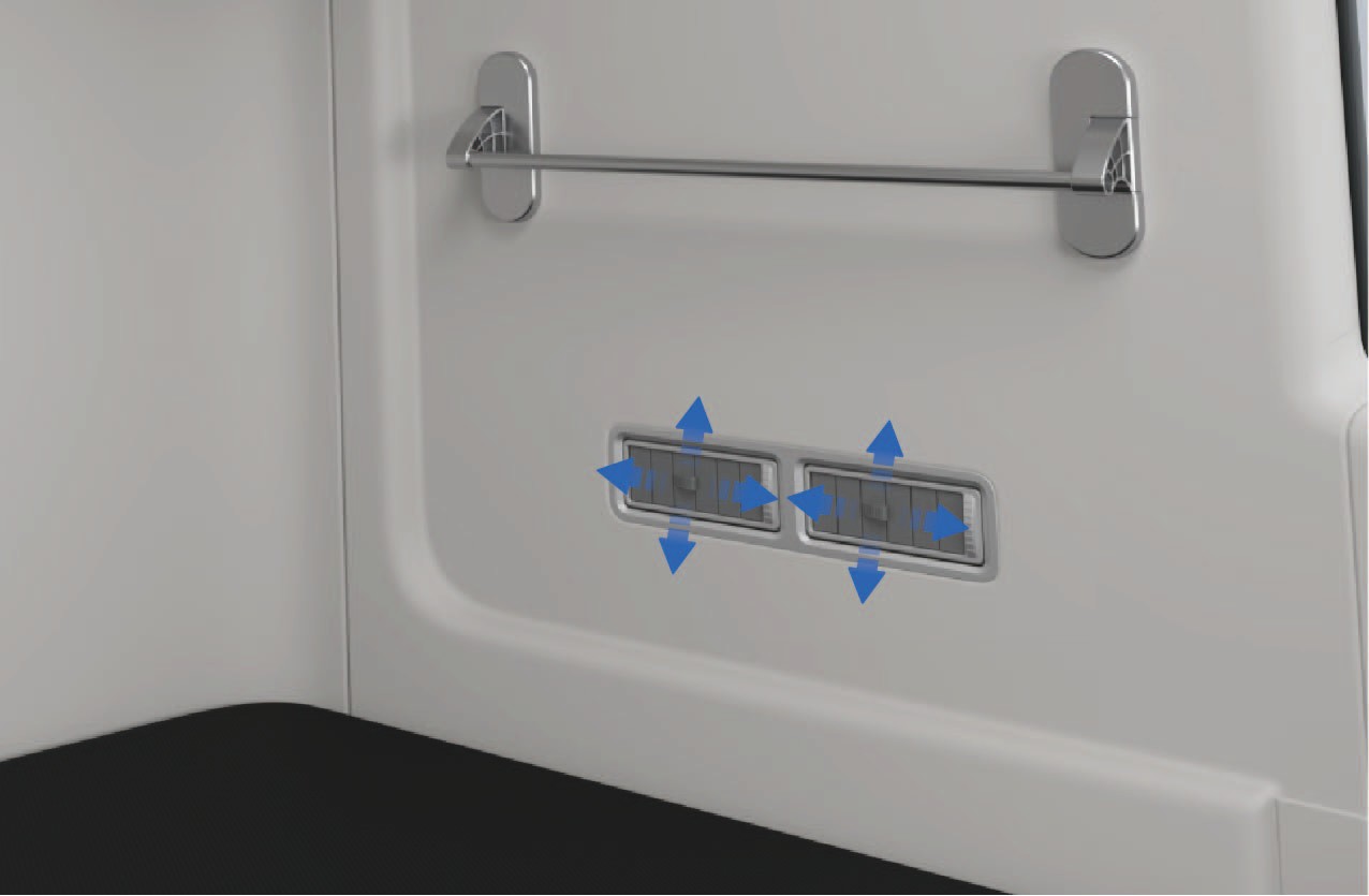
The front A/C vents are located in the windshield, the instrument panel and the legroom under the instrument panel. The rear A/C vents are located on the left side of the sleeper in the vehicle.
Operating instructions
Adjustment of front A/C vent
↑ TopYou can manually adjust the paddles at the front vent to control the up and down or left and right blowing angle of the front vent.
Adjustment of rear A/C vent
You can manually adjust the paddles at the rear vent. You can turn the paddle up and down to adjust the up and down blowing angles of the rear vent, or turn the paddle left and right to adjust the left and right blowing angles of the rear A/C vent or close the vent. Keep at least one vent open when adjusting the rear A/C vents.
Precautions
↑ TopNoticeWhen adjusting the vent paddles, do not apply great force to avoid damage to paddles.
In-Vehicle Fragrance
↑ TopA/C on Vehicle
The vehicle has an in-vehicle fragrance device, which can be mounted in the fragrance box in the lower trim area on the right side of the driver seat according to your personal preferences.
Operating instructions
Open the cap of the fragrance bottle, insert the thin end of the fragrance bottle into the hole in the fragrance mechanism above the right lower trim area of the seat, and press down gently to install the fragrance bottle in place.
Once the fragrance bottle is inserted into the hole, it will be adsorbed into place by the magnet in the fragrance
mechanism.
After the fragrance bottle is installed in place, the information of the fragrance inserted into the current hole will be prompted on the vehicle information screen.
When changing the fragrance bottle, you need to pinch the bottom of the fragrance bottle with your fingers and slowly remove the fragrance bottle from the fragrance mechanism.
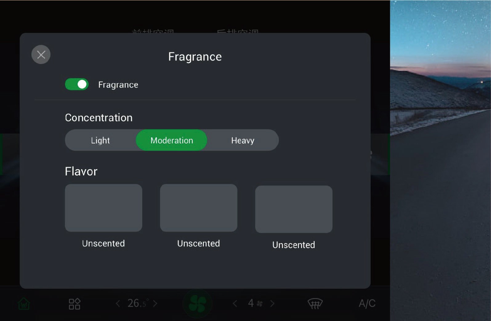
After the fragrance is successfully installed, you can enter the A/C setting interface in the vehicle information screen, and click "Fragrance" to turn on/off the fragrance system, adjust the concentration of the corresponding fragrance and select different flavors of fragrance in this interface.
Precautions
Warning
Keep the fragrance bottle out of the reach of children so as to avoid poisoning caused by accidental ingestion of substances in the bottle.
Do not insert your fingers into the cavity of the fragrance mechanism to avoid personal injury.
Do not install or replace the fragrance bottle while driving to avoid accidents.
If you feel uncomfortable when using the fragrance, stop using
the fragrance system immediately.
In case personnel with allergic or respiratory diseases are sitting in the vehicle, use the fragrance system with caution.
Notice
Pay attention to the expiration date of the fragrance bottle before installation. The unpacked fragrance lasts for 1 year, while the packed one lasts for 3 months. Use the fragrance within the expiration date and replace the fragrance when it reaches the expiration date.
When replacing the fragrance bottle, keep hands clean and ensure the fragrance system is functioning properly.
A magnet is mounted below the fragrance mechanism. Do not put mobile phones, tablets and other electronic devices close to the fragrance hole above the open storage area of the central control, so as to avoid affecting the function of electronic devices and fragrance modules.
Since fragrances may react chemically with organic matters, direct contact with the plastic parts is prohibited for the ceramic fragrance core in the bottle.
Note
 The fragrance experience will vary with the interior temperature, the A/C volume, and your physiological state.
The ceramic fragrance core in the fragrance bottle should be purchased through official channels so as to avoid damage to the fragrance bottle and ensure the quality of the fragrance.
After installation of the fragrance bottle, if the fragrance system is not successfully recognized, install the fragrance bottle again.
Charging Port
Vehicle Charging
 Charging port
The vehicle has charging ports on both sides.
Operating instructions
↑ TopInterior operation
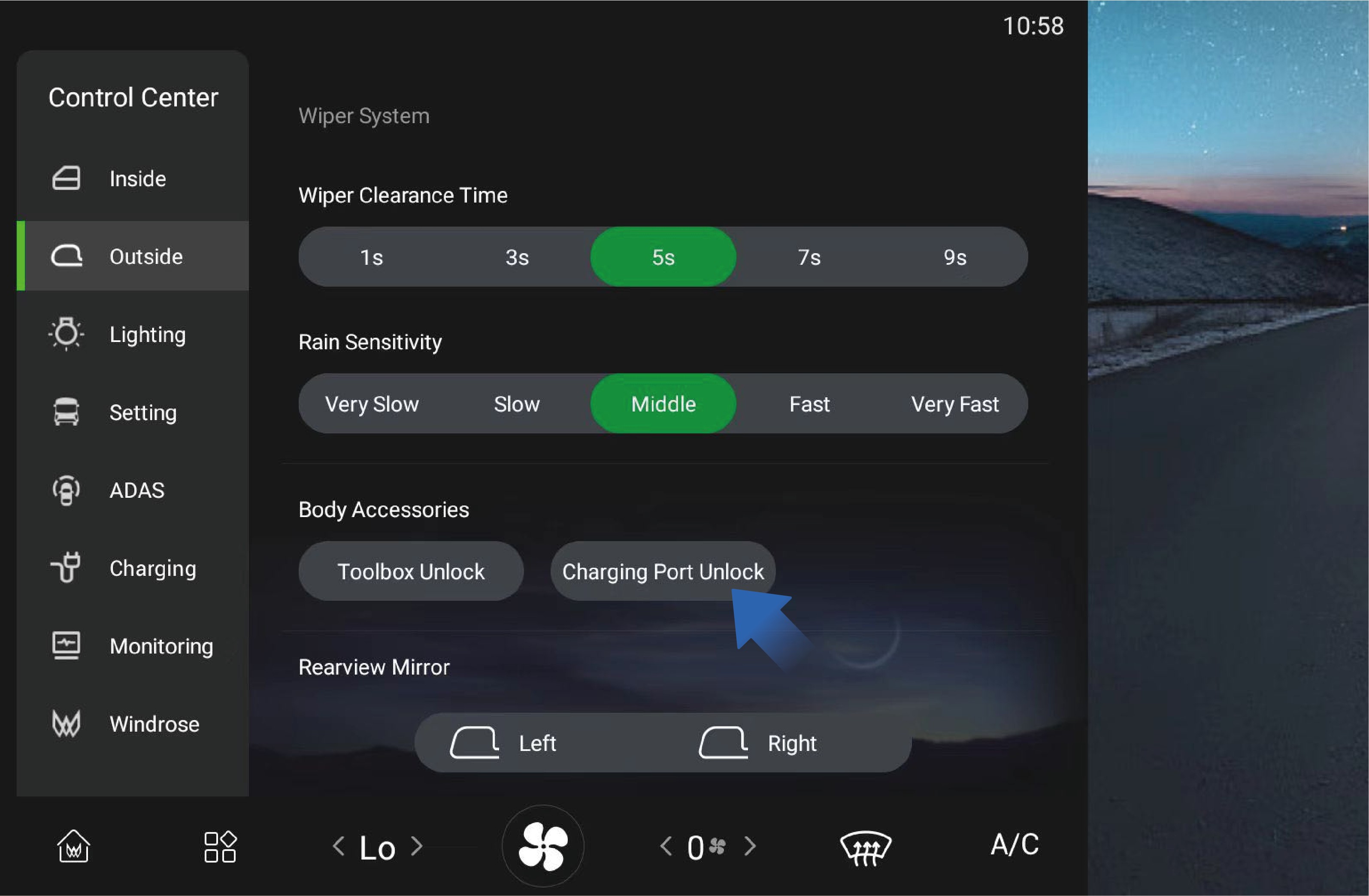
You can unlock the charging port cover by selecting "Control Center", switching to "Outside" interface, and clicking "Charging Port Unlock" button on the vehicle information screen of the instrument panel, and the charging port cover can be properly activated by pressing at this time.
Precautions
Note
The charging port cover can only be unlocked instead of being closed through the vehicle information screen in the vehicle. To close the charging port cover, you still need to operate it outside the vehicle.
Charging Preparation
↑ TopVehicle Charging
When charging this vehicle, please use a charging device with a voltage ≥ 1000V to charge the vehicle. Charging devices smaller than this standard will not be able to charge the vehicle.
Operating instructions
Preparation
Check the charging pile cable and vehicle charging socket for damage, immersion, ablation and other obvious abnormalities, and make sure there are no obvious safety hazards in the charging pile and the surrounding environment before charging.
Park the vehicle near the charging device and make ensure the vehicle is free of any abnormalities such as insulation fault. The vehicle can be charged both under high-voltage and non- high-voltage conditions.
Charging preparation
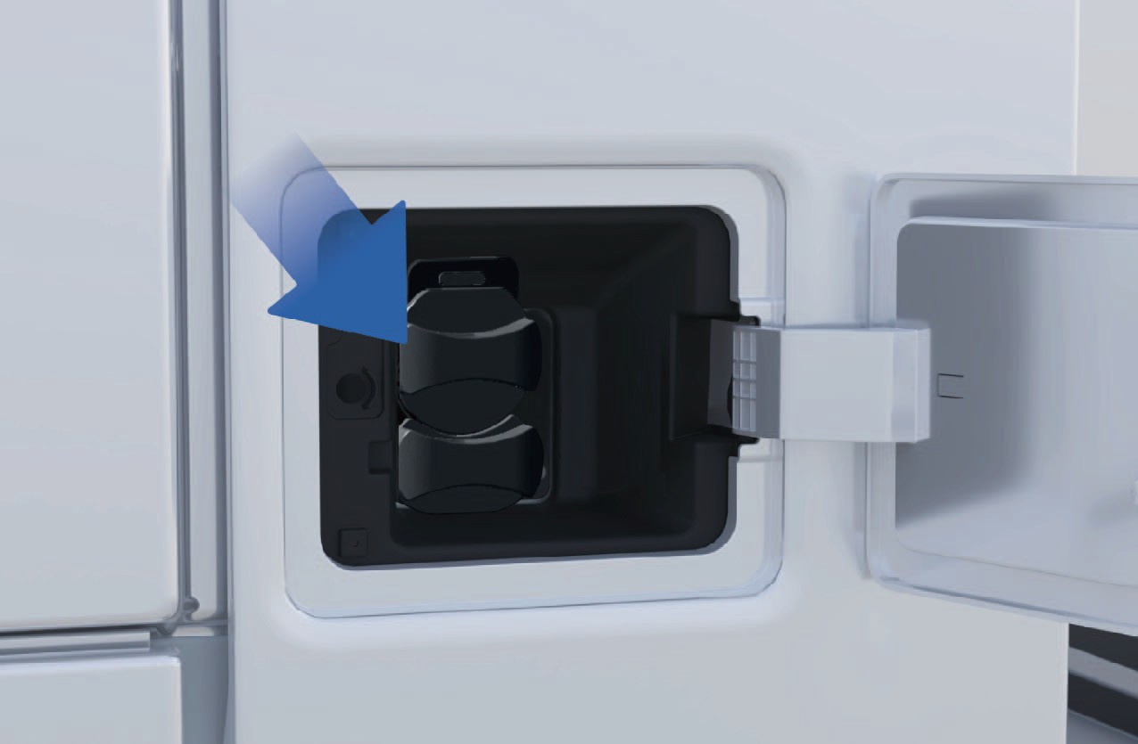
Insert the charging plug connector into the charging port. When it is inserted in place, you can hear a "click" sound which means that the connection is successful. Then the charging port electronic lock will be activated, and the instrument cluster will display the charging connection prompt icon.
Follow the instructions on the charging screen to start the charging process by swiping the card or scanning the code.
On the display of the charging pile, select the corresponding
charging mode and charging parameters, confirm that the information is correct, and click "Start charging" button to start charging the vehicle by the charging device. The charging pile display will indicate the charging progress, charging time, charging power and other information in real time.
During charging, you can actively click "Stop charging" button to stop charging. When the charging is completed, the device display will show that the charging is complete. You should click "Stop charging" button to stop charging the device and unlock the charging port electronic lock. Unplug the charging plug and put it back to the plug base of the charging device.
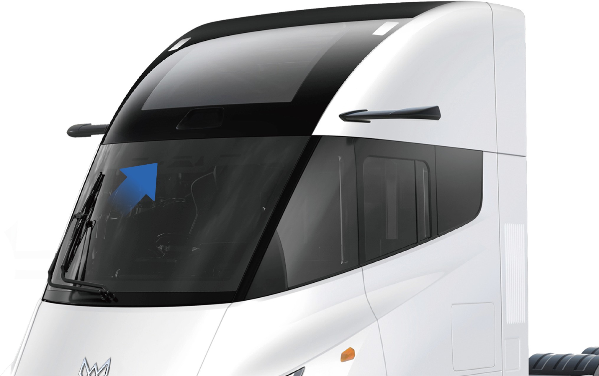
Charging indicator
The indicator on the top of the windshield will change into a charging indicator during charging of the vehicle. When the high-voltage battery SOC is lower than 30%, the left charging indicator flashes; When the high-voltage battery SOC becomes 30%-90%, the left charging indicator remains on; When the high voltage
battery SOC is greater than 90%, the left and middle charging indicators remain on and the right charging indicator flashes; When the high-voltage battery SOC reaches 100%, the left, middle
and right charging indicators remain on.
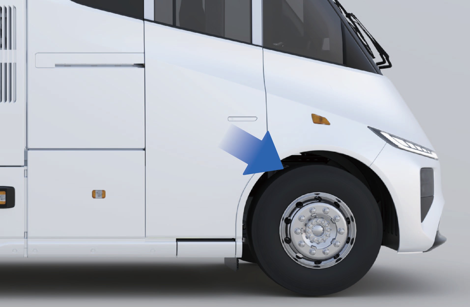
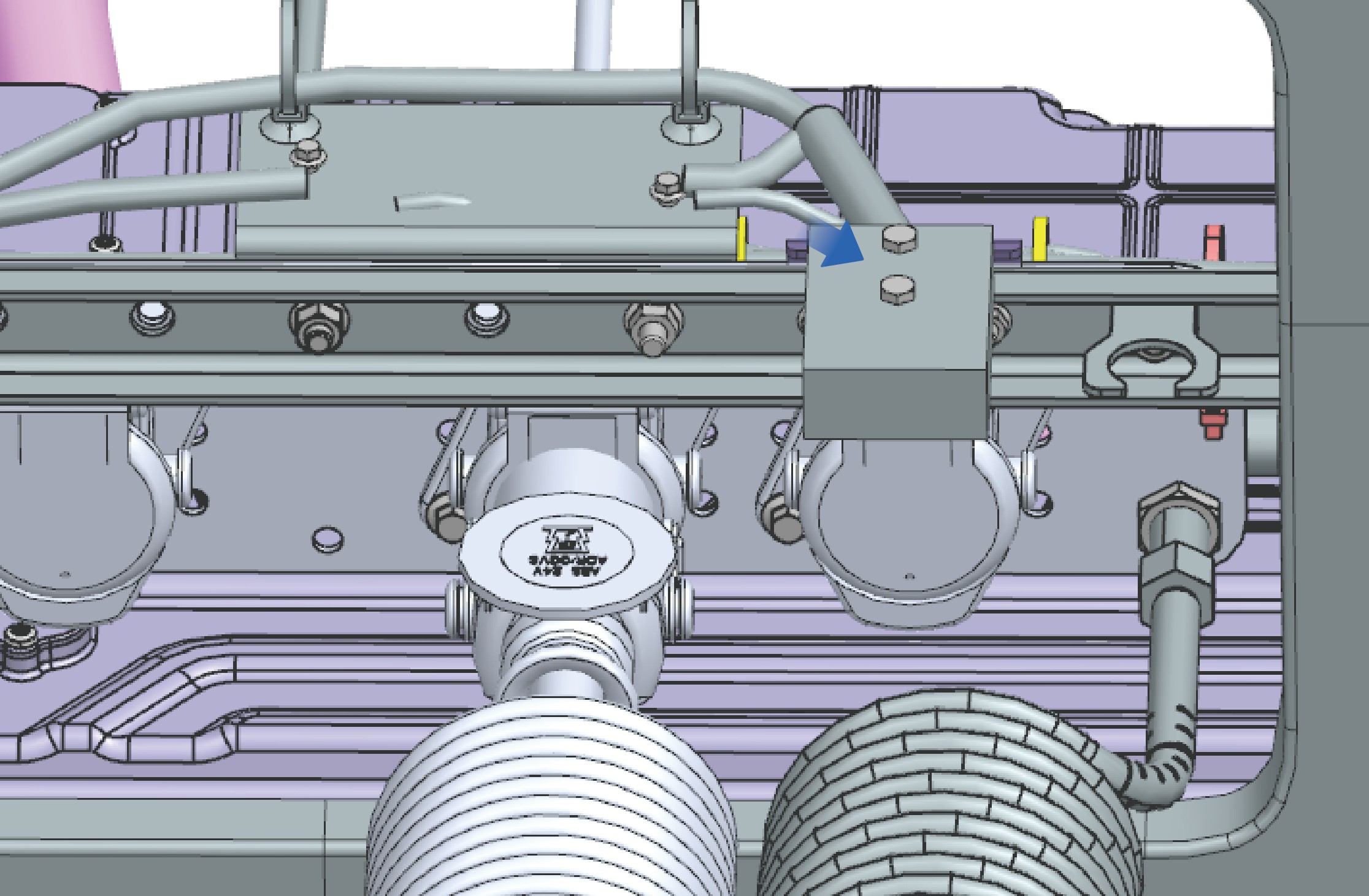
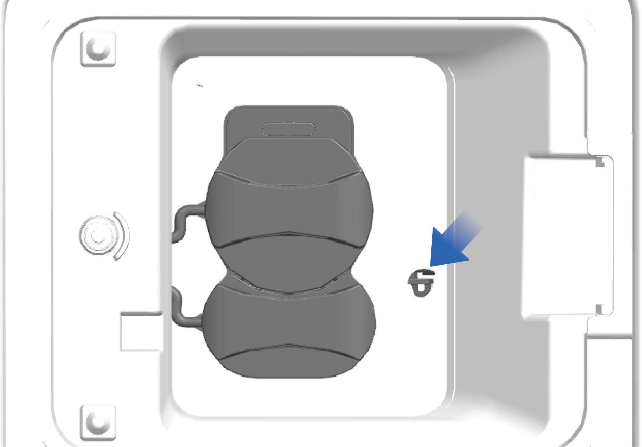
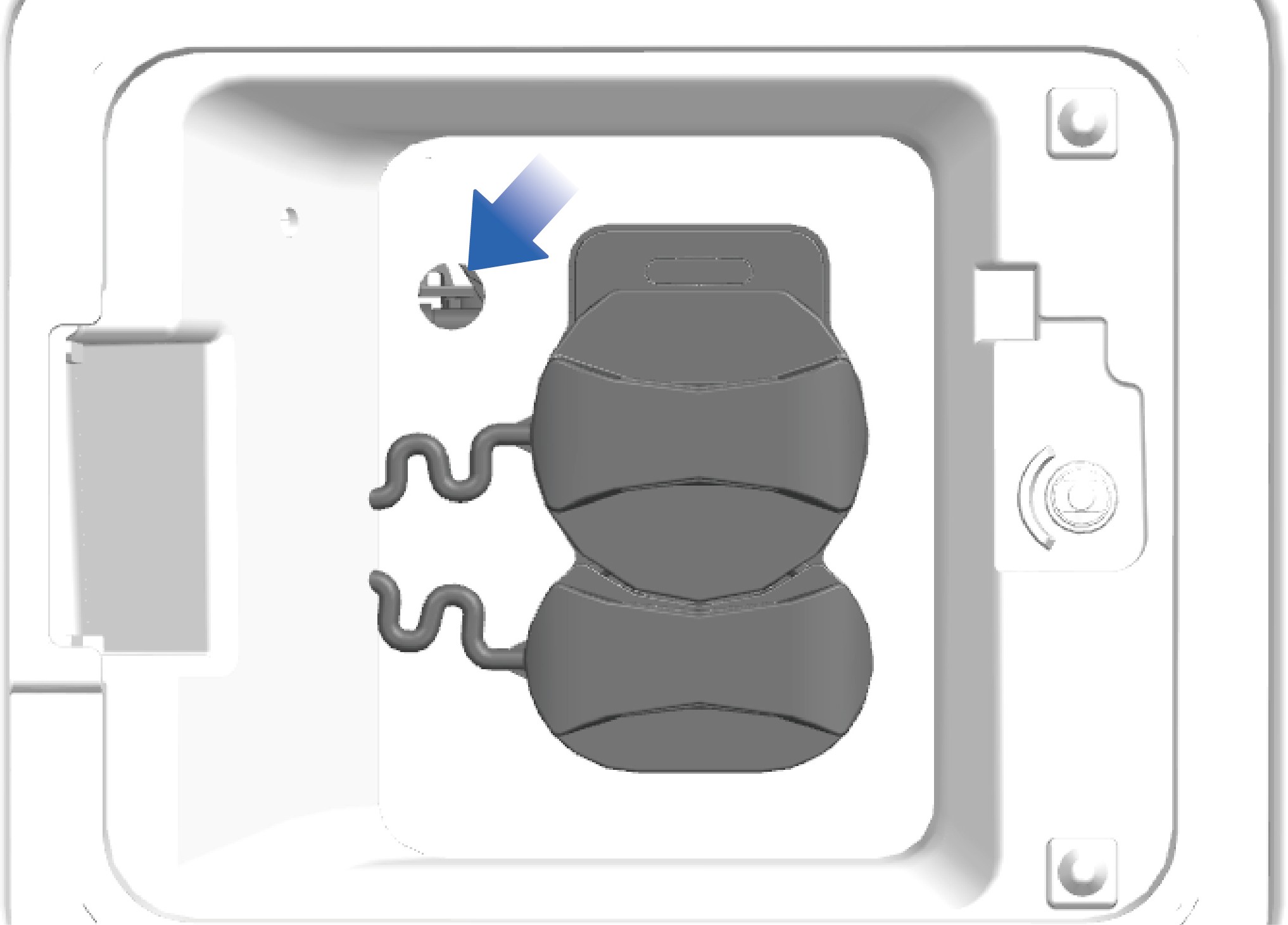
Emergency unlocking
↑ Top
If the charging gun cannot be pulled out after charging is completed, the emergency unlocking mechanism beside the charging socket can be used to unlock it. Use a tool to push the unlocking mechanism towards the inside of the vehicle, changing its position from parallel to the vehicle's forward direction to perpendicular to it. Location of the emergency unlocking mechanism for the charging socket.
Precautions
Warning
Before charging, it is important to confirm that the charging output voltage platform and the low-voltage auxiliary power supply are matched with the vehicle, and the charging connector is in line with the requirements of regulations.
It is forbidden to stack flammable and explosive materials around the charging pile, and it is important to keep the surrounding environment of the charging device well ventilated.
During charging, it is forbidden to touch the charging plug connector and the vehicle charging port to avoid electric shock.
If the device is found abnormal, for example, smoking, emitting odor, making abnormal noise, etc., stop charging immediately and contact a professional for maintenance.
Unlock the vehicle before inserting/pulling out the charging
plug without any skewing, shaking and aggressive operation.
The charging port electronic lock will be activated and fixed when the charging starts, thus it is forbidden to unplug the charging plug violently; When the charging ends, unlock the
vehicle and end the charging in the vehicle information screen to release the charging port electronic lock.
Do not operate the electronic lock unlocking bolt during normal charging.
NoticeOver-discharge of the high-voltage battery should be avoided as much as possible to ensure the safe service life of the high-voltage battery. When the high-voltage battery SOC is lower than 20%, the instrument cluster will display an alarm prompt indicating that the high-voltage battery SOC is too low; When the high-voltage battery SOC is lower than 5%, the vehicle will enter the power limit mode, and the vehicle speed will decrease with the increase of the depth of discharge (DoD) of the high-voltage battery. In this case, find a charging device nearby as soon as possible to charge the vehicle.
The high-voltage battery should be used under a temperature of 50 °F– 86 °F. The service life of the high-voltage battery will be shortened under too high or too low ambient temperature.
If the vehicle is not used for a long time, the main power switch should be turned off, and the high-voltage battery should be charged once every half month.
When the vehicle is in under-voltage protection state, you should charge it in time before use. Otherwise, over-discharge of the high-voltage battery may happen, affecting the performance and service life of the high-voltage battery.
Note
The vehicle cannot be charged if the charging port electronic lock is not activated, which can be checked by turning the charging plug slightly.
Driving Preparation
Preparation Before Driving
Before using the vehicle, check it to ensure safety:
Check the connection and fastening of each part.
Check whether the motor and E-axle make abnormal noise during working.
Check the installation of the accessories.
Check the oil level in the E-axle and steering oil tank.
Check the fluid level in the windshield washer and coolant kettle.
Check the oil condition at each lubrication point.
Check whether the brake system and steering system are working properly.
Check whether the electrical equipment and pipelines are well connected.
Check tire pressure.
Check whether the driver's tools and on-board technical literature are complete.
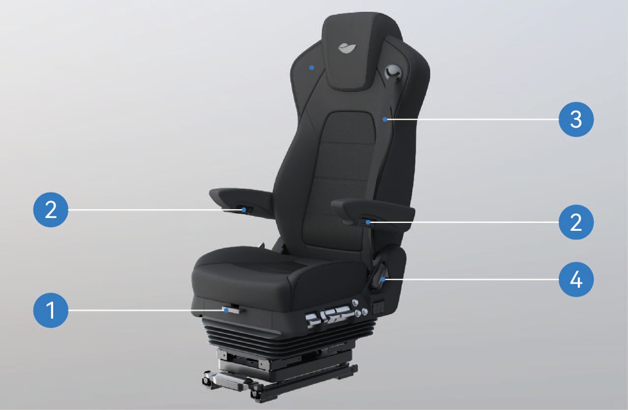
Driver Seat
↑ TopPreparation Before Driving
You can adjust the functions of the driver seat according to your personal needs and preferences to deliver more comfortable experience during driving.
Operating instructions
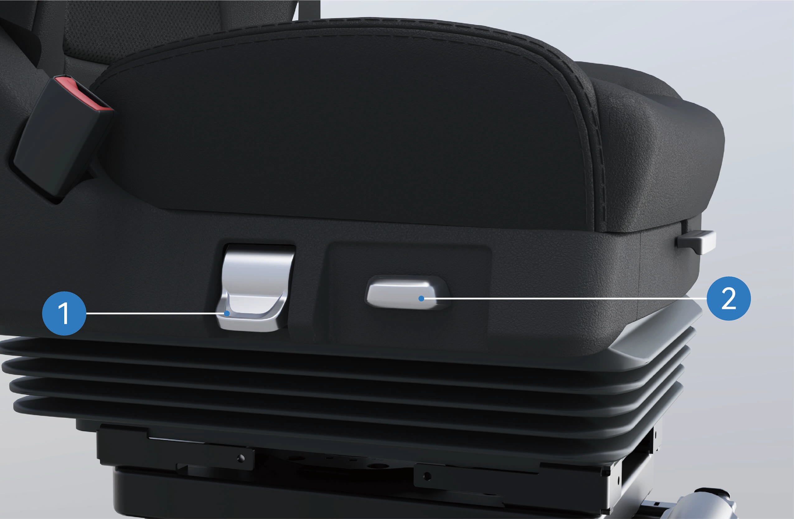
Driver's Seat Cushion Fore-and-Aft Adjustment Lever
Lift and hold the lever, slide the cushion forward or backward by yourself, and release the unlock lever when arriving at a proper position to lock the cushion.
Driver's Seat Armrest Knob
Rotate the armrest knob to adjust the armrest. When rotating the armrest knob to the left, the armrest will be lowered; When rotating the armrest knob to the right, the handrail will raise.
Driver's Seat Belt
You can directly pull out the seat belt to use it.
Driver's Seat Backrest Angle Adjustment Handle
Lift the backrest angle adjustment handle to unlock the back- rest; lean back gently against the backrest or move slowly away fromittoadjustthebackresttoyourdesiredangle.Releasethehan- dle and the backrest will lock automatically.
Driver's Seat Rotation Adjustment Handle
Toggle the driver's seat rotation handle, and the seat can ro- tate 90° toward the car door.
Driver's Seat Fore-and-Aft Adjustment Switch
Toggle the switch forward or backward to adjust the fore-and- aft position of the seat.
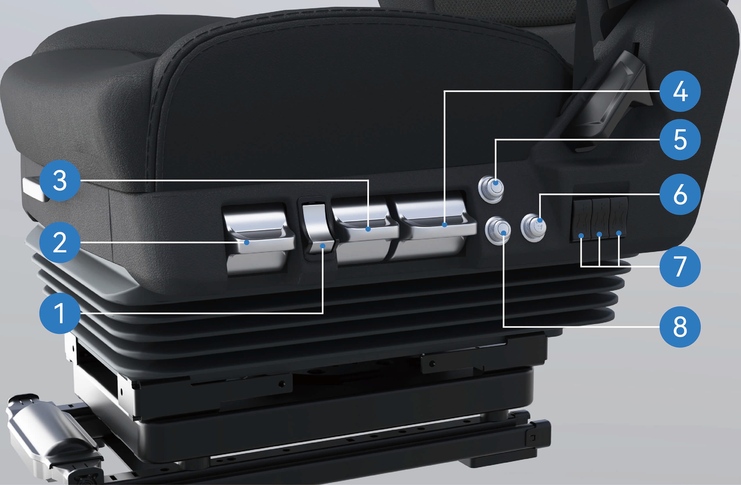
Driver's Seat Quick Deflation Button Pressthelowerpartofthequickdeflationbuttonandtheseatwilllow- er rapidly; press the upper part and the sewithout following proper procedures inflate quick- ly and rise to the normal use position.
Driver's Seat Tilt Adjustment Handle
Toggle the tilt handle up or down to change the vertical tilt an- gle of the cushion, and release the handle to lock the cush- ion when you find a comfortable position.
Driver's Seat Damping Adjustment Handle
Toggle the damping handle up or down to adjust the firm- ness of the seat.
Driver's Seat Height Adjustment Handle
Toggletheseatheightadjustmenthandleuptoraisetheseat; tog- gle it down to lower the seat.
Driver's Seat Heating Knob
Rotate the seat heating knob to turn the heating func- tion on or off; the knob is adjustable for three heating levels: High, Medium and Low.
Driver's Seat Massage Knob
Rotate the seat massage knob to turn the massage func- tion on or off; the knob is adjustable for three massage modes: Level 1: Bottom-to-top regional massage
Level 2: Lower regional massage Level 3: Upper regional massage
Driver's Seat Lumbar Support Adjustment Buttons
Press the upper part of the button to raise the lumbar sup- port; press the lower part to lower the lumbar support.
Driver's Seat Ventilation Knob
↑ TopRotate the seat ventilation knob to turn the ventilation func- tion on or off; the knob is adjustable for three air volume levels: High, Medium and Low.
Precautions
Warning
Do not adjust the seat while the vehicle is in motion, otherwise it may cause the vehicle to lose control, resulting in accidents.
Do not incline the seat backrest excessively, otherwise the seat belt will fail to provide sufficient protection effect. For example, in the event of an accident or sudden braking, the person wearing the seat belt of the over-inclined seat may get lower than the seat belt and thus injured.
The seat shall be adjusted correctly to ensure proper depressing of the brake pedal.
Before driving, shake the driver seat back and forth to ensure that it is locked in place, otherwise, injury may occur in the event of an accident or sudden braking.
Before moving the seat, make sure that the seat movement area is unobstructed so as to prevent damaging items or pinching occupants.
Notice
Check that no other objects are getting stuck in the seat in the cab. Otherwise, the seat may be damaged.
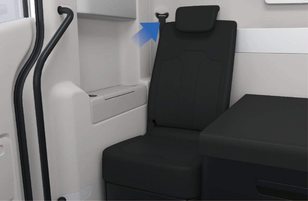
Front Passenger Seat
↑ TopPreparation Before Driving
The front passenger seat is situated on the right side of the sleeper in the vehicle. You can uncover the headrest of the sleeper and adjust the backrest of the front passenger seat in vertical position to sit in the front passenger seat.
Operating instructions
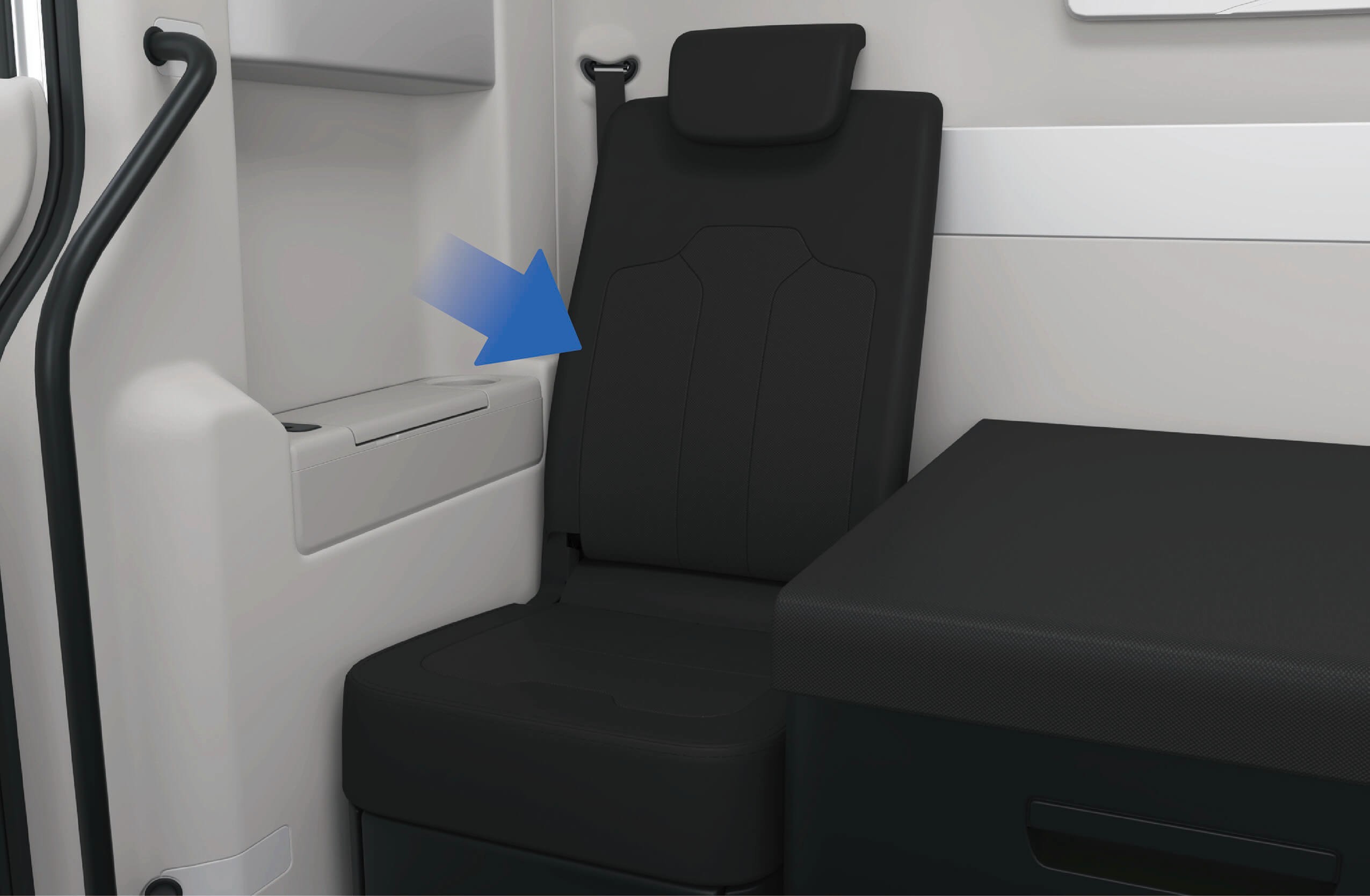
↑ TopTo use the headrest of the front passenger seat, you should lift the headrest up and move it to the highest position; When you do not need to use the front passenger seat headrest, press down on the headrest to move it downward. The headrest is available for use only in the highest position.
To put away the front passenger seat, you can pull the unlock webbing behind the seat backrest to unlock the seat backrest, and fold the backrest.
Precautions
Notice
When adjusting the headrest of the front passenger seat upwards, stop lifting the headrest forcefully if you feel that the headrest cannot move any more, so as not to damage the headrest mechanism.
When folding the backrest of the front passenger seat, make sure that there are no items on the seat so as to avoid damage to the front passenger seat mechanism when folding the backrest.
↑ TopNote
NFC Card
↑ TopPreparation Before Driving
The vehicle is designed with a NFC Card, which allows you to unlock, lock, power ON and power OFF the vehicle.
Operating instructions
↑ TopSwipe the NFC Card in the middle of the surface of the flush door handle, then the door handle lamp will be illuminated, and the vehicle indicator lamps will flash once simultaneously to indicate successful unlocking; Swipe the NFC Card on the surface of the
flush door handle again, then the door handle lamp will go out, and the vehicle indicator lamps will flash twice simultaneously to indicate successful locking.
After the vehicle is unlocked, you can swipe the NFC Card on the designated swiping position of the right instrument panel to power ON the vehicle.
To power OFF the vehicle, you can either click "Power OFF" on the vehicle information screen or swipe the NFC Card on the designated swiping position of the right instrument panel.
Precautions
Notice
Do not bend, twist, or cut the NFC Card.
Do not place NFC Card in high temperature, damp or strongly vibrating areas.
Do not place the NFC Card on any household wireless charging device to avoid damage.
Do not put the NFC Card in the phone case to avoid damaging the NFC Card when it comes into contact with the wireless charging device.
Do not expose the NFC Card in the vehicle to avoid the deformation and failure of the NFC Card.
Do not use the same type of card (bank card, transportation card, ID card or access cards, etc.) together with the NFC card (overlapping, swiping at the same time, etc.).
Note
When unlocking/locking the vehicle with NFC Card, you should keep the vehicle stationary and swipe the NFC Card on the surface of the flush door handle.
After swiping the NFC Card, you should take the NFC Card away from the designated swiping position in time to prevent repeated triggering of the swiping action.
If the surface of the flush door handle is contaminated by dirt or frost, the sensing effect of the NFC Card may be effected, resulting in failure to unlock/lock the vehicle.
If any NFC Card is lost or additional tags need to be ordered, contact Windrose service hotline.
Mechanical Key
↑ TopPreparation Before Driving
If the vehicle cannot be unlocked using digital key and NFC Card under certain special circumstances, you can use the mechanical key to unlock the vehicle in an emergency.
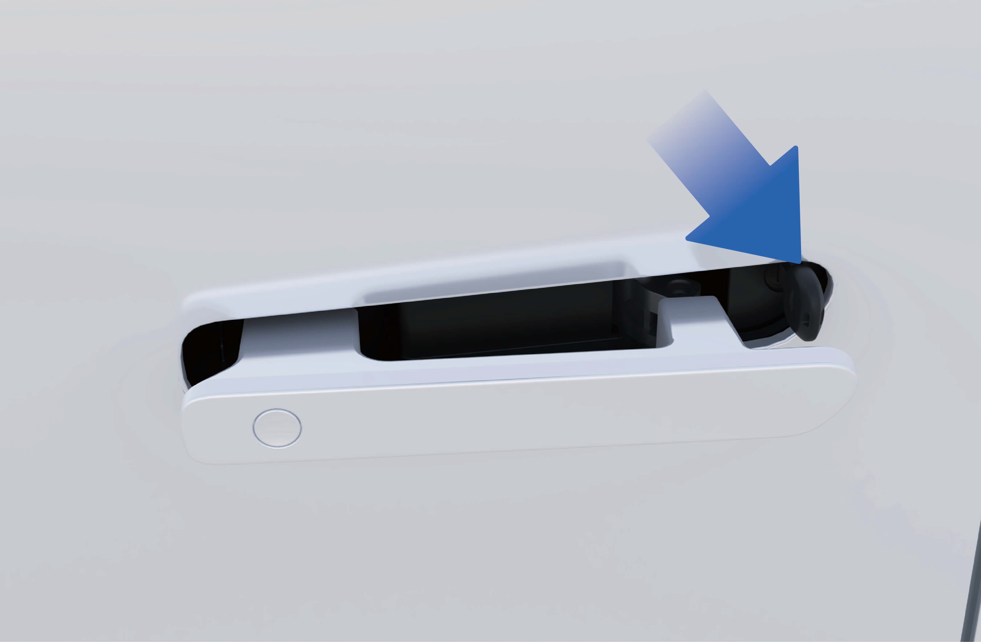
When you press the front end of the flush door handle, the rear end of the flush door handle will tilt. And, at this time, you can pull out the flush door handle of the vehicle as a whole and hold with your fingers.
2. Insert the mechanical key into the door keyhole below the flush door handle and rotate the mechanical key to the right to unlock the vehicle.
Notice
- When pulling the flush door handle, keep at horizontal position to prevent the interference between the front end of the flush door handle and the door from damaging to the vehicle paint.
Please keep the mechanical key properly to avoid losing the key which will lead to failure in unlocking the vehicle in an emergency.
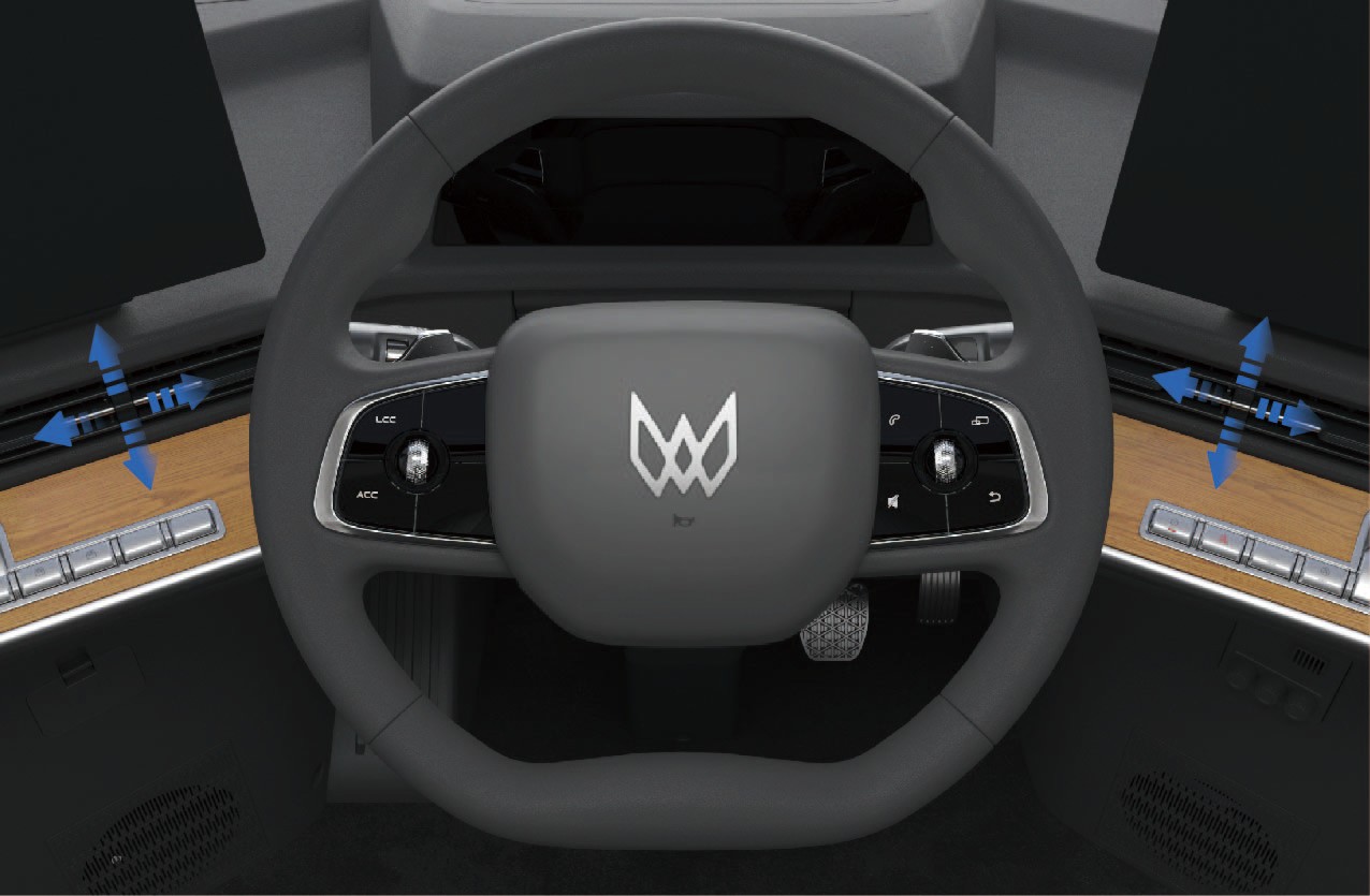
Adjustment of Steering Wheel
↑ TopPreparation Before Driving
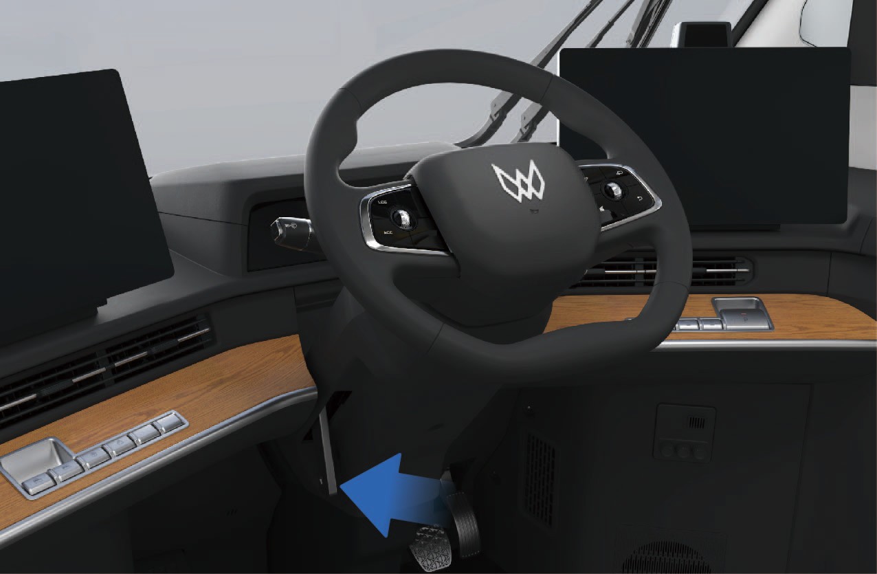
The steering wheel can be adjusted forward, backward, up and down to suit your driving needs.
Never adjust the steering wheel while driving to avoid accidents.
After adjusting the steering wheel position, make sure that the steering wheel is locked, otherwise it will cause personal injury or death and property damage.
Buttons on Steering Wheel
Preparation Before Driving
Pull up the steering wheel adjustment handle to unlock the steering wheel.
Manually adjust the steering wheel height and distance to your body according to your needs.
After the adjustment is completed, push down the steering wheel adjustment handle to lock the steering wheel.
Function introduction
↑ TopThe vehicle is equipped with a multi-function steering wheel, allowing you to easily control certain functions in the vehicle.
Operating instructions
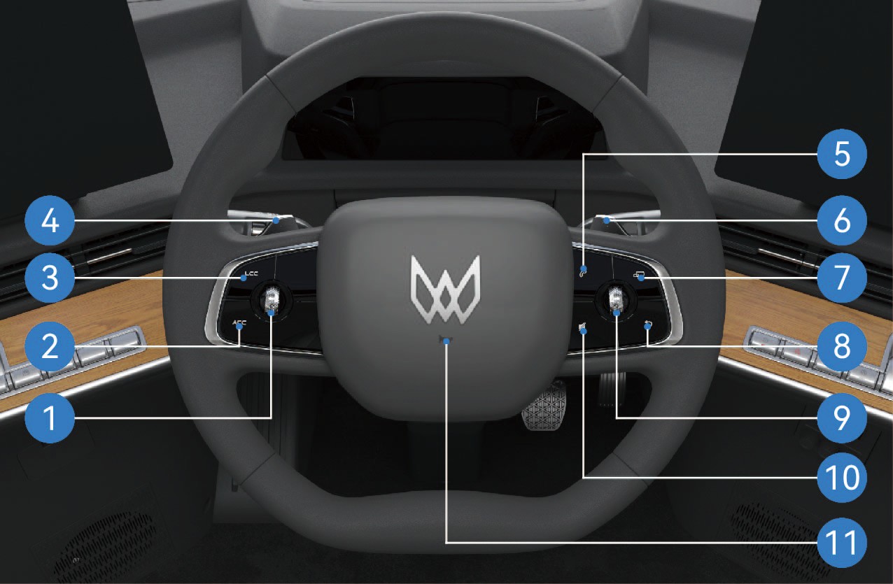
Confirmation, distance and speed adjustment button
Turn the scroll wheel to the left to reduce the following distance in cruise state; Turn the scroll wheel to the right to increase the following distance in cruise state.
Turn the scroll wheel upwards to increase the vehicle speed in cruise state; Turn the scroll wheel downward to reduce the vehicle speed in cruise state.
Press the middle of the scroll wheel to determine the selected target.
Activation of adaptive cruise control (ACC) function
Press once to activate ACC function; Press again to turn off ACC function.
Activation of lane centering control (LCC)*
Press once to activate LCC function; Press again to turn off LCC function.
Kinetic regenerative braking paddle (left)
Turn the left paddle of kinetic regenerative braking system (KERS) to reduce the kinetic regenerative braking intensity of the vehicle.
Bluetooth phone
Press once to answer a Bluetooth call.
Press and hold to hang up the phone or make a call.
Kinetic regenerative braking paddle (right)
Turn the right paddle of kinetic regenerative braking system (KERS) to increase the kinetic regenerative braking intensity of the vehicle.
MODE function
Press this button to switch between radio, music, and video.
Return
Press this button to return to the previous interface of the recently operated vehicle information screen. To switch to
another vehicle information screen, manually touch the corresponding vehicle information screen.
Multimedia control
Turn the scroll wheel to the left to return the selected multimedia function to previous function; Turn the scroll wheel to the right to switch the selected multimedia function to next function.
Turn the scroll wheel upward to increase the volume of the selected multimedia function; Turn the scroll wheel downward to decrease the volume of the selected multimedia function.
Press the middle of the scroll wheel to determine the selected target in the corresponding media list.
Mute
Press once to turn on the mute state; Press again to restore the sound.
Horn
↑ TopPress the center of the steering wheel to make the horn.
You can click "Inside" in the "Control Center" interface of the vehicle information screen to select the horn type of the vehicle.

Precautions
↑ TopNotePlace your fingers at a suitable position to avoid the situation that the key may be inaccessible or difficult to operate.
Overview of Instrument Cluster
Preparation Before Driving
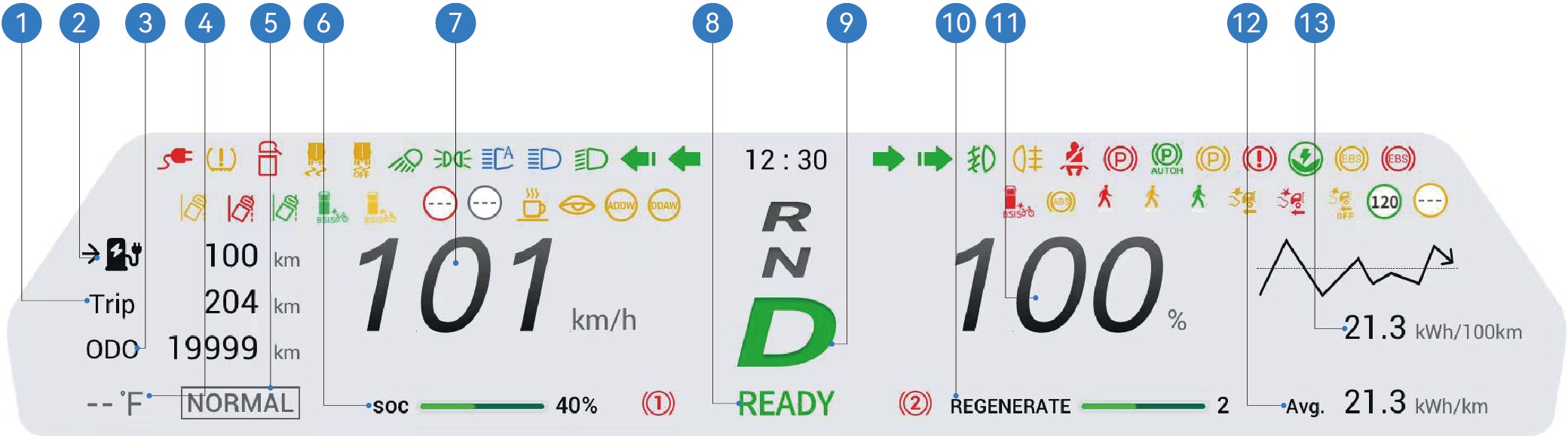
Trip 5. Driving mode 9. Current vehicle gear 13.Instantaneous power consumption per 100 miles
Estimated driving range 6. High voltage battery capacity 10.Energy recovery levels
Odometer (total distance) 7. Current speed 11.Proportion of instantaneous
power driven
Exterior temperature 8. Vehicle is ready 12.Average power consumption
per 100 miles
You can select "Windrose" in the "Control Center" interface of the vehicle information screen to select day, night or auto mode.
Day mode: The base color of the instrument cluster is white;
Night mode: The base color of the instrument cluster is black;
Auto mode: The system automatically adjusts between day and night mode based on the outdoor light.
↑ TopNoticeThe pictures on the instrument cluster interface are all schematic diagrams for reference only. Please refer to the actual vehicle.
Indicators and Warning Lamps
Preparation Before Driving
|
|
|
|---|---|---|
|
|
|
|
|
|
|
|
|
|
|
|
|
|
|
|
|
|
|
|
|
|
|
|
|
|


|
|
|
|---|---|---|
|
|
|
|
|
|
|
|
|
|
|
|
|
|
|
|
|
|
|
|
|
|
|
|
|
|
|
|
|


|
|
|
|---|---|---|
|
|
|
|
|
|
|
|
|
|
|
|
|
|
|
|
|
|
|
|
|
|
|
|
|
|
|
|
|


|
|
|
|---|---|---|
|
|
|
|
|
|
|
|
|
|
|
|
|
|
|
|
|
|
|
|
|
|
|
|
|
|
|
|
|


|
|
|
|---|---|---|
|
|
|
|
|
|
|
|
|
|
|
|
|
|
|
|
|
|
|
|
|
|
|
|
|
|
|
|
|


|
|
|
|---|---|---|
|
|
|
|
|
|
|
|
|
|
|
|
|
|
|
|
|
|
|
|
|
|
|
|
|
|
|
|
|


|
|
|
|---|---|---|
|
|
|
|
|
|
|
|
|
|
|
|
|
|
|
|
|
|
|
|
|
|
|
|
|
|
|
|
|


|
|
|
|---|---|---|
|
|
|
|
|
|
|
|
|
|
|
|
|
|
|
|
|
|
|
/ | |
|
/ | |
|
/ | |
|
/ |


|
|
|
|---|---|---|
|
/ | |
|
/ |


When the vehicle is powered on, some warning lamps will be illuminated for self-test and go out after a few seconds. If the warning lamp remains illuminated or gets illuminated during driving due to a fault, you should attach importance to this phenomenon and contact a Windrose authorized service center as soon as possible to avoid accidents which may lead to personal injury or property damage.
If the warning lamp remains illuminated after the vehicle is powered on, or gets illuminated during driving, it indicates that the vehicle may be subject to a serious fault. In this case, contact a Windrose authorized service center immediately.
↑ TopThe black icons in the table will change between black and white according to the background in the instrument cluster display.
Wiper Control
↑ TopPreparation Before Driving
When you release the windshield washing button, the water spraying will stop immediately, and the wiper will reset after three wipes. When you press and release the windshield washing button, the washer does not spray water, and the
You control the functions of wipers on the vehicle through the
combination switch handle on the left side of the steering wheel.
Operating instructions
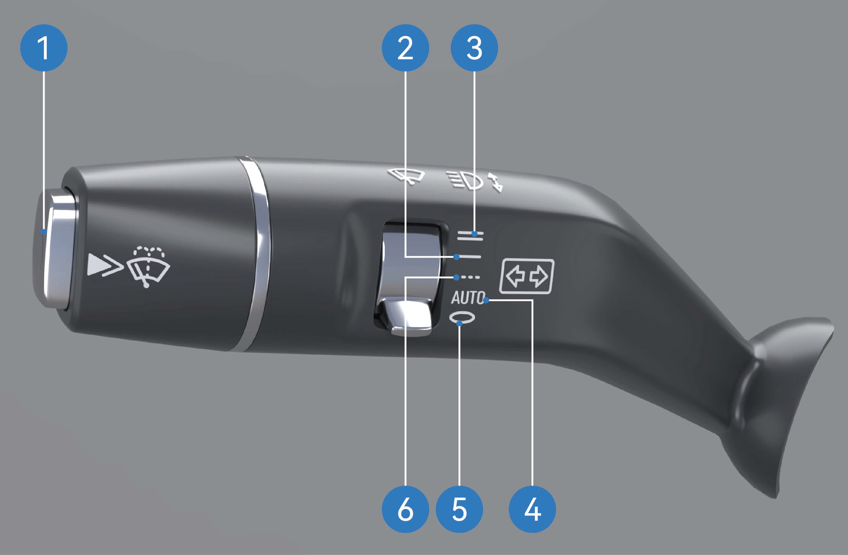
Windshield washing: Press and hold the windshield washing button to enter the washing mode. In this mode, the washer will keep spraying water, and the wiper will wipe continuously.
wiper will be reset after one wipe.
Low-speed continuous wiping: Move the wiper blade to this position, and the wiper will enter low-speed continuous wiping mode.
High-speed continuous wiping: Move the wiper blade to this position, and the wiper will enter high-speed continuous wiping mode.
Auto wiping: Move the wiper blade to this position, and the wiper will enter auto wiping mode.
Wiper OFF: Move the wiper blade to this position, and the wiper will be in off mode.
Intermittent wiping: Move the wiper blade to this position, and the wiper will enter intermittent wiping mode, in which you can adjust the intermittent wiping frequency of the wiper in the vehicle information screen.
↑ Top
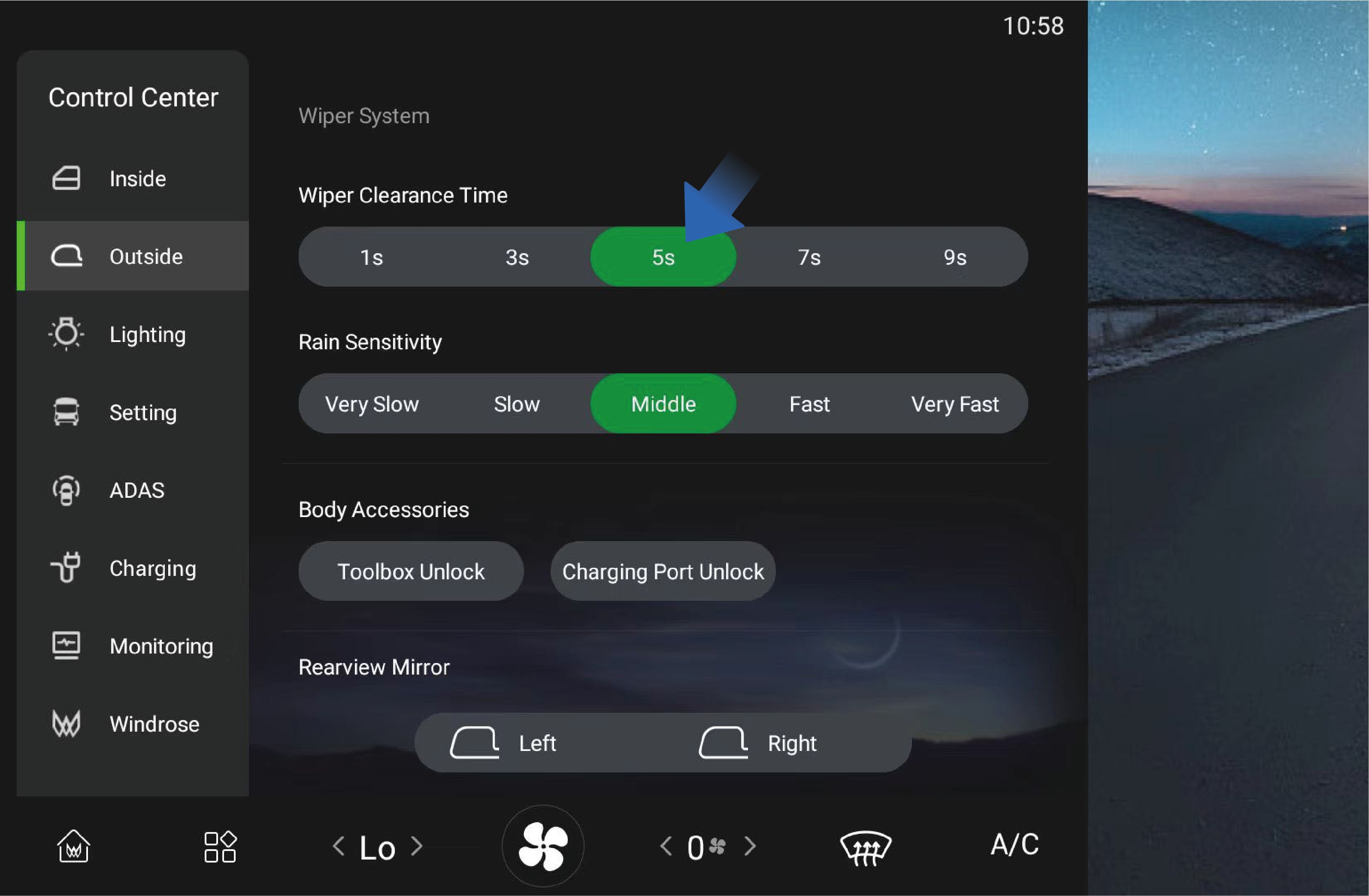
You can click "Outside" in the "Control Center" interface of the vehicle information screen to select the wiper intermittent wiping interval according to your needs.
When the wiper blade is moved to auto wiping position, you can also select the rain sensitivity in this interface, and the system will adjust the auto wiping frequency according to the sensitivity you selected.
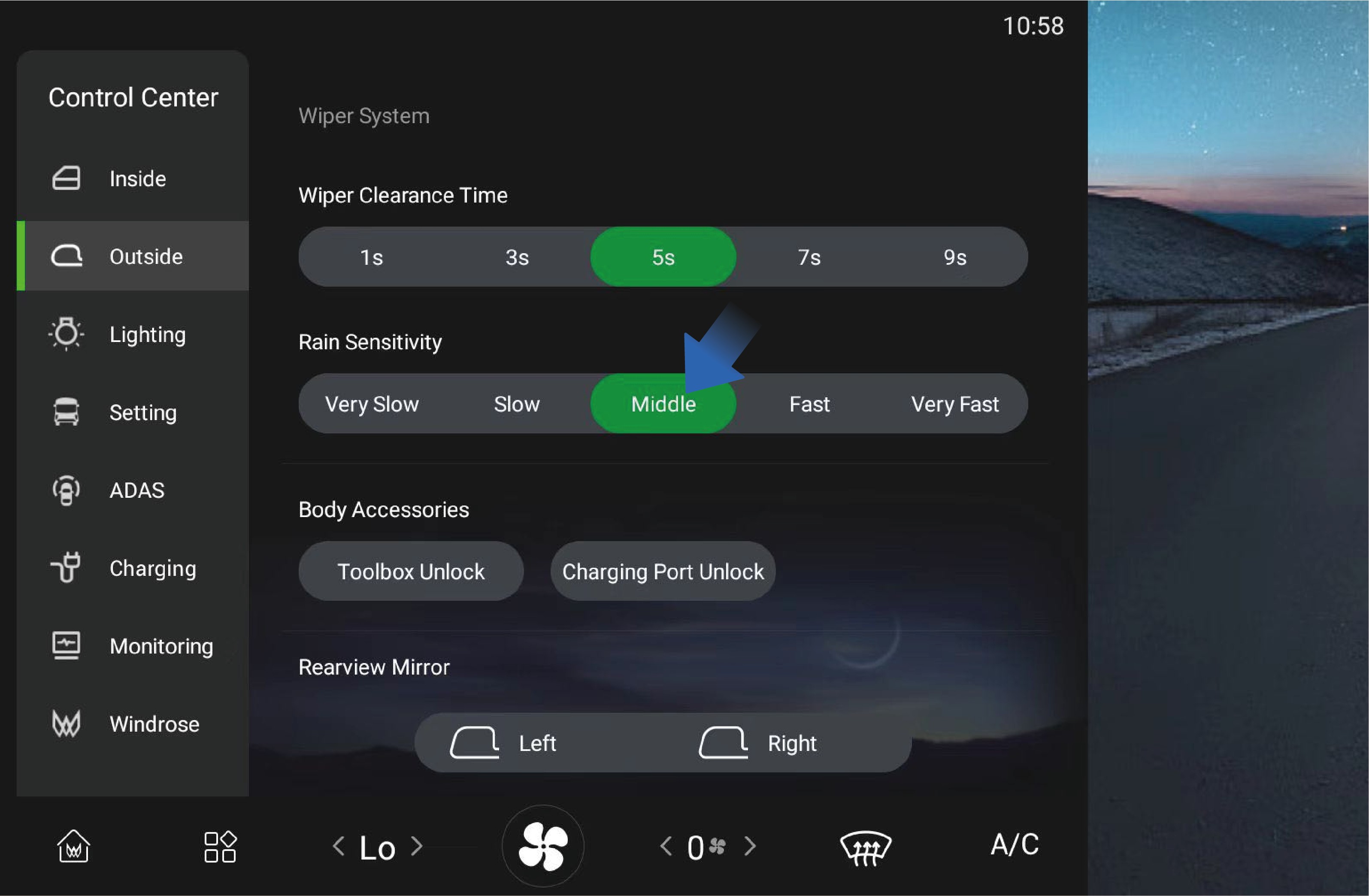
Precautions
WarningIn cold weather, if the washer fluid freezes on the windshield, do not use the wipers, as this may obstruct the view and cause traffic accidents or casualties.
Notice
Before using the wipers in winter, be sure to remove the ice and snow from the windshield to ensure that the wiper blades are not frozen at fixed positions.
Light Switch
↑ Top
Preparation Before Driving
Do not rely solely on the automatic wipers. Always adjust the wiping manually according to the actual situation.
Note
When there are foreign objects such as dust, bird droppings, insects, and tree sap on the windshield, please clean the windshield first, otherwise the wiper blades may be damaged.
Wipers should be used to clean the windshield with washer fluid. Otherwise, both the wiper and the windshield may be damaged.
Check the wiper blades on a regular basis. If scheduled maintenance is not carried out properly, the service life of the wiper blades will be shortened.
Please use acceptable detergent, as non-conforming detergent products may cause damage to the washer or corrosion to the glass.
After turning on the automatic headlamps or light switch in the
vehicle information screen, you can switch between low and high beams through the light stalk on the left side of the steering wheel. Proper use of exterior lights can effectively improve the driving safety of a vehicle.
 Operating instructions
Click "Lighting" icon in the "Control Center" interface of the vehicle information screen to enter the vehicle light control interface, where you can click the position lamp (outline marker lamp), low beam or AUTO icon to activate the external lights of the vehicle.
Once the exterior lights are activated, you can switch between low and high beams through the light stalk on the left side of the steering wheel.
Move the light stalk forward to turn on the high beam.
Move the light stalk backward to turn off the high beam.
With the high beam not turned on, move the light stalk backwards and release, then the light stalk will automatically reset and the passing lamp will flash once.
Move the light stalk downward to turn on the left turn signal.
Move the light stalk upward to turn on the right turn signal.
Daytime running lamp
After the vehicle is started, the daytime running lamp will be automatically turned on when the low beam is turned off; When the low beam is turned on, the daytime running lamp will turn off automatically.
Side marker combination lamp
Side marker combination lamps are designed on both sides of the vehicle, which will be automatically turned on when the "AUTO", "Low beam" or "Position lamp" is turned on in the light control interface of the vehicle.
Rear working lamp

↑ TopIf it is necessary to turn on the rear working lamp of the vehicle in a specific situation, you can click "Rear Work Lights" switch in "Lighting" interface.
Precautions
↑ TopNoteWhen operating the turn signals, there is no need to activate the exterior lights in advance in the vehicle information screen.
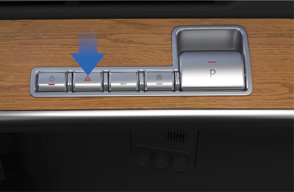
Hazard Warning Lamp Switch
Preparation Before Driving
↑ TopIn the case of an emergency while driving, immediately turn on the hazard warning lamp to alert the vehicle behind, thereby avoiding accidents.
 Operating instructions
↑ TopWhen pressing the hazard warning lamp switch on the right side of the instrument panel in the vehicle, if the indicator on the switch flashes, it indicates that the hazard warning lamp has been activated.
Precautions
↑ TopWarningThe hazard warning lamp switch is used under conditions that the vehicle may cause traffic accidents or other special situations to alert passing vehicles to avoid accidents.
Power ON/OFF
↑ TopDriving
After the vehicle is unlocked, open the door and swipe the NFC Card at the designated swiping position of the right instrument panel to power ON the vehicle, and the instrument cluster and center display will be illuminated.
If you are in the vehicle, you can power ON or off the vehicle
through the NFC Card. Operating instructions Power on
Power off
Before powering off the vehicle, make sure the vehicle is safe and stably parked. When parking on a ramp or special locations, fix the wheels using the parking wedges that come with the vehicle to avoid slipping.
When the above conditions are met, you can power OFF the vehicle as follows.
Method 1:
With the EPB turned on, swipe the NFC Card at the designated swiping position of the right instrument panel to power off the vehicle.
Method 2:
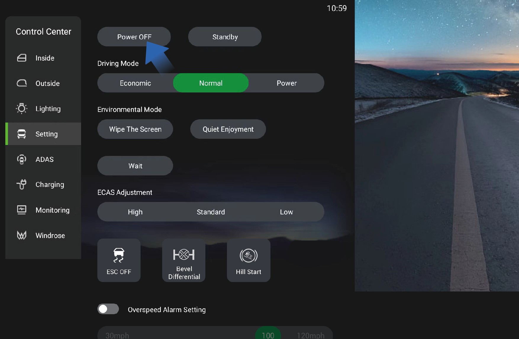 Precautions
↑ TopNoteDuring the vehicle power-off, you will hear a sound, which is a normal phenomenon caused by the self-test of braking system.
Service Brake
↑ TopDriving
With the EPB turned on, you can power OFF the vehicle by selecting "Control Center", switching to "Setting" interface, and clicking "Power OFF" button in the right IVI screen.
After powering off the vehicle from inside the vehicle, the electric switch of the power sliding door inside or outside the vehicle can still be used to open or close the power sliding door. When the power sliding door is locked from outside the vehicle, it means the vehicle has been successfully powered off.
To slow down or stop the vehicle during driving, you can depress the brake pedal to reduce the vehicle speed or slow down until the vehicle comes to a complete stop.
Operating instructions
To stop the vehicle smoothly during service braking, it is recommended to operate the brake pedal as follows in three situations:
Deceleration: In case it is necessary to slow down during high-speed driving, first completely release the accelerator pedal to reduce the vehicle speed by the drive motor, and if the
deceleration is not as expected, depress the brake pedal appropriately;
Stop: Gradually depress the brake pedal to reduce the vehicle speed, fully depress the brake pedal when arriving at the parking position, switch to N (neutral) gear, and turn on EPB to power OFF the vehicle and complete the parking operation.
Emergency braking: In case of an emergency, depress the brake pedal with great force quickly to stop the vehicle immediately.
Precautions
Warning
When entering a curve, brake in advance to reduce the vehicle speed below the safe speed, and drive cautiously when braking at the curve to avoid vehicle sideslip.
The service brake is not suitable for prolonged braking (e.g., long-term downhill driving) as this can cause safety hazards for service brake. In case continuous braking is required when driving down on a long slope, turn on the auxiliary braking for electric regenerative braking.
In rainy and snowy weather, increase the following distance appropriately to ensure driving safety.
Electronic Parking Brake (EPB)
Driving
↑ Top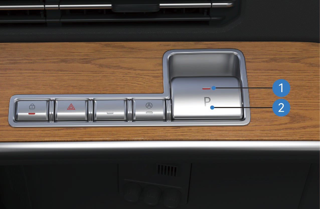
EPB Parking Brake Switch Status Indicator
EPB Parking Brake Switch
Operating instructions
Parking Brake Release
Manual Release
When the vehicle is in the parking brake state with normal system self-check and air reservoir pressure, depress the brake pedal and press the EPB Parking Brake Switch to release the parking brake; the parking brake indicator light on the combination instrument will go out.
Automatic Release on Start-up
When the vehicle door is closed, the vehicle is in the parking brake state (on flat roads or ramps) with normal system self-check and air reservoir pressure, the parking brake will be automatically released when the vehicle starts normally; the parking brake indicator light on the combination instrument will go out.
NoteThe system cannot automatically release the parking brake when shifting to reverse gear (R). Please release the parking brake manually before shifting to R.
Low-pressure Release Restriction
The parking brake cannot be released when the air reservoir pressure is too low. The parking brake indicator light on the combination instrument will stay on, and a corresponding text prompt will be displayed.
Forced Low-pressure Parking Brake Release
If the parking brake cannot be released due to excessively low air reservoir pressure, depress the brake pedal and press and hold the EPB Parking Brake Switch for more than 5 seconds to release the parking brake; the parking brake indicator light on the combination instrument will go out.
Child Lock Function
The parking brake cannot be released if you press the EPB Parking Brake Switch without depressing the brake pedal first, and a corresponding text prompt will be displayed on the combination instrument.
Emergency Parking Brake Release
When the vehicle is in the parking brake state with normal system self-check and air reservoir pressure, power ON the vehicle and press the EPB Parking Brake Switch quickly 5 times within 10 seconds after power-on to release the parking brake; the parking brake indicator light on the combination instrument will go out.
Towing Mode
When the vehicle is in the parking brake state with normal system self-check and air reservoir pressure: Press and hold the EPB Parking Brake Switch; Tap the Power OFF button on the vehicle infotainment screen (do not power OFF via card swiping); Release the EPB Parking Brake Switch after holding for more than 5 seconds. After the vehicle is powered off, the EPB system will not activate the parking brake and remain in the released state. The parking brake indicator light on the combination instrument will go out, and the EPB Parking Brake Switch Status Indicator will flash until the system enters dormancy.
Parking Brake Activation
Manual Activation
When the vehicle is stationary and in the parking brake released state with normal system self-check and air reservoir pressure, pull up the EPB Parking Brake Switch to activate the parking brake; the parking brake indicator light on the combination instrument will turn on.
Activation on Vehicle Power-off
When the vehicle is stationary and in the parking brake released state with normal system self-check, tap the Power OFF button on the right vehicle control screen (do not power OFF via card swiping) to activate the parking brake; the parking brake indicator light on the combination instrument will turn on and go out 10 seconds after power-off.
Emergency Braking
When the vehicle is in driving state with a failure of the service brake system (and normal system self-check and air reservoir pressure): Slowly pull up the EPB Parking Brake Switch to activate the EPB emergency braking; If the vehicle speed is below 3 mph when the switch is pulled up to the maximum travel, the system will fully activate the parking brake. The travel of the EPB Parking Brake Switch is proportional to the braking force. The brake light will turn on when emergency braking is activated during driving; the parking light will not turn on if the emergency braking does not trigger the parking brake function.
Dormancy and Wake-up
When the EPB system is in dormancy (the switch status indicator is off), pull up the EPB Parking Brake Switch to wake
up the system, and the EPB Parking Brake Switch Status Indicator will turn on.
Temporary Parking
The Temporary Parking Switch is located on the right side of the instrument panel.
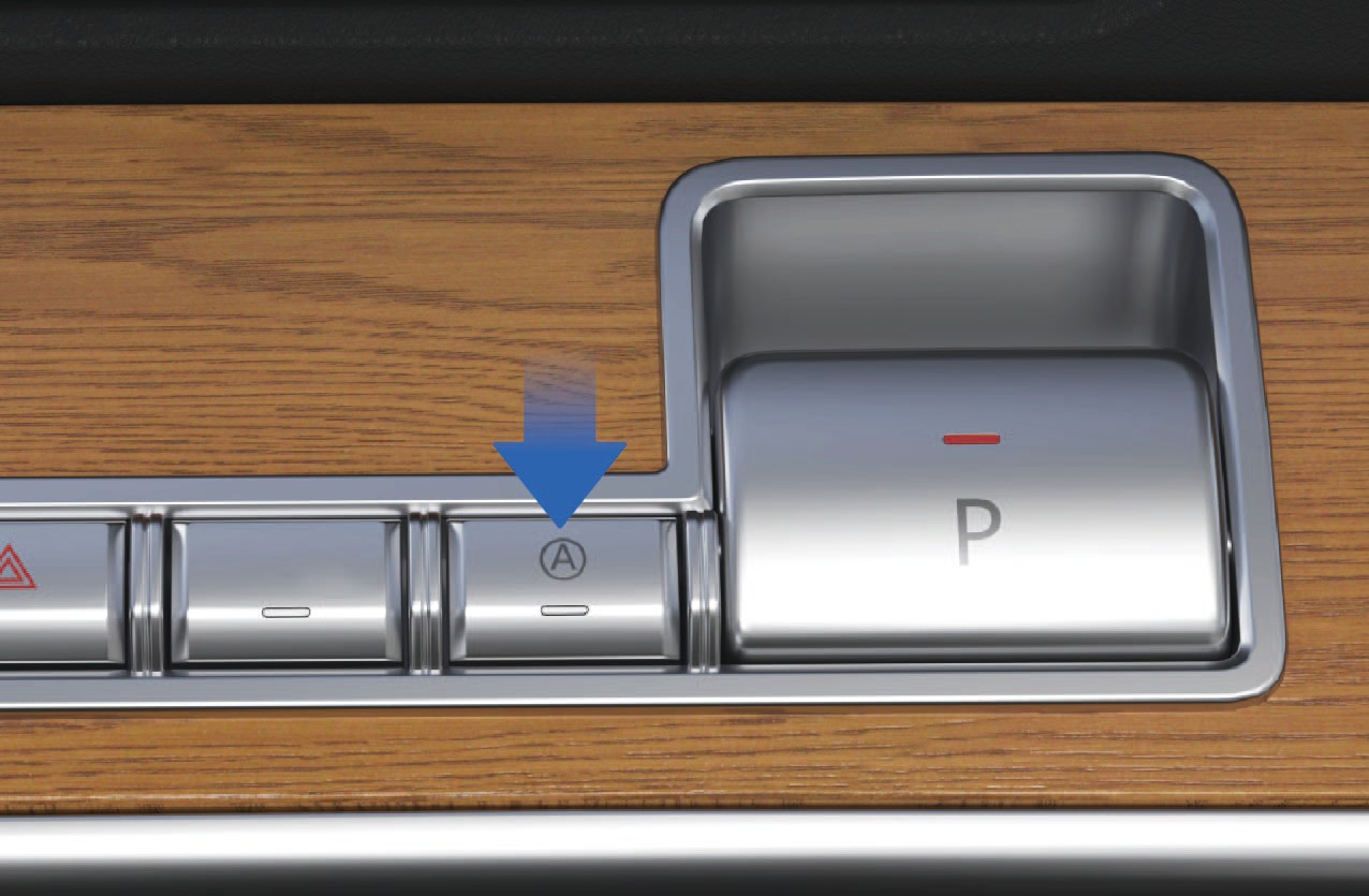
Activation and Deactivation of Temporary Parking
When the vehicle is stationary with normal system self-check, press the Temporary Parking Switch to activate the function (press the switch again to deactivate it).
Activated state: The AUTO HOLD indicator light on the combination instrument and the Temporary Parking Switch Status Indicator turn on; Deactivated state: The AUTO HOLD indicator light on the combination instrument and the Temporary Parking Switch Status Indicator turn off.
Temporary Parking Activation via Service Brake
When the vehicle is stationary with normal system self-check and air reservoir pressure, depress the brake pedal to a certain depth and hold for more than 3 seconds to activate temporary parking. The AUTO HOLD indicator light on the combination instrument and the Temporary Parking Switch Status Indicator will flash.
Temporary Parking Brake Release
When the vehicle door is closed, the vehicle is in the temporary parking state (on flat roads or ramps) with normal system self-check and air reservoir pressure, the temporary parking brake will be released when the vehicle starts normally. The AUTO HOLD indicator light on the combination instrument and the Temporary Parking Switch Status Indicator will cease flashing and remain on.
NoteThe system cannot automatically release the temporary parking brake when shifting to reverse gear (R). Please release the temporary parking brake manually before shifting to R.
Fault Alerts
Fault Alert During Parking: The parking brake indicator light on the combination instrument and the EPB Parking Brake Switch Status Indicator flash simultaneously.
Fault Alert During Parking Brake Release: The parking brake indicator light on the combination instrument turns yellow, and the EPB Parking Brake Switch Status Indicator flashes.
Precautions
Warning
When the air reservoir pressure is too low, try to release the parking brake only after the pressure is restored to normal.
When parking on a slope, choose a hardened road surface with a high friction coefficient to prevent vehicle rollback caused by loose pavement or insufficient static friction.
Use a parking chock when parking on a slope; add auxiliary objects such as stones according to the actual slope gradient to avoid accidental rollback.
The parking brake can be used temporarily as the service brake in an emergency, but long-term replacement of the service brake is prohibited.
Notice
Release the EPB via normal operation unless necessary (i.e., when air reservoir pressure is sufficient).
During forced parking brake release, observe the surrounding road conditions to ensure the safety of the vehicle, pedestrians and other road users before operation.
Emergency Braking - Driving
Driving
↑ TopThe parking brake can be used as an emergency brake when the vehicle's service brake system malfunctions.
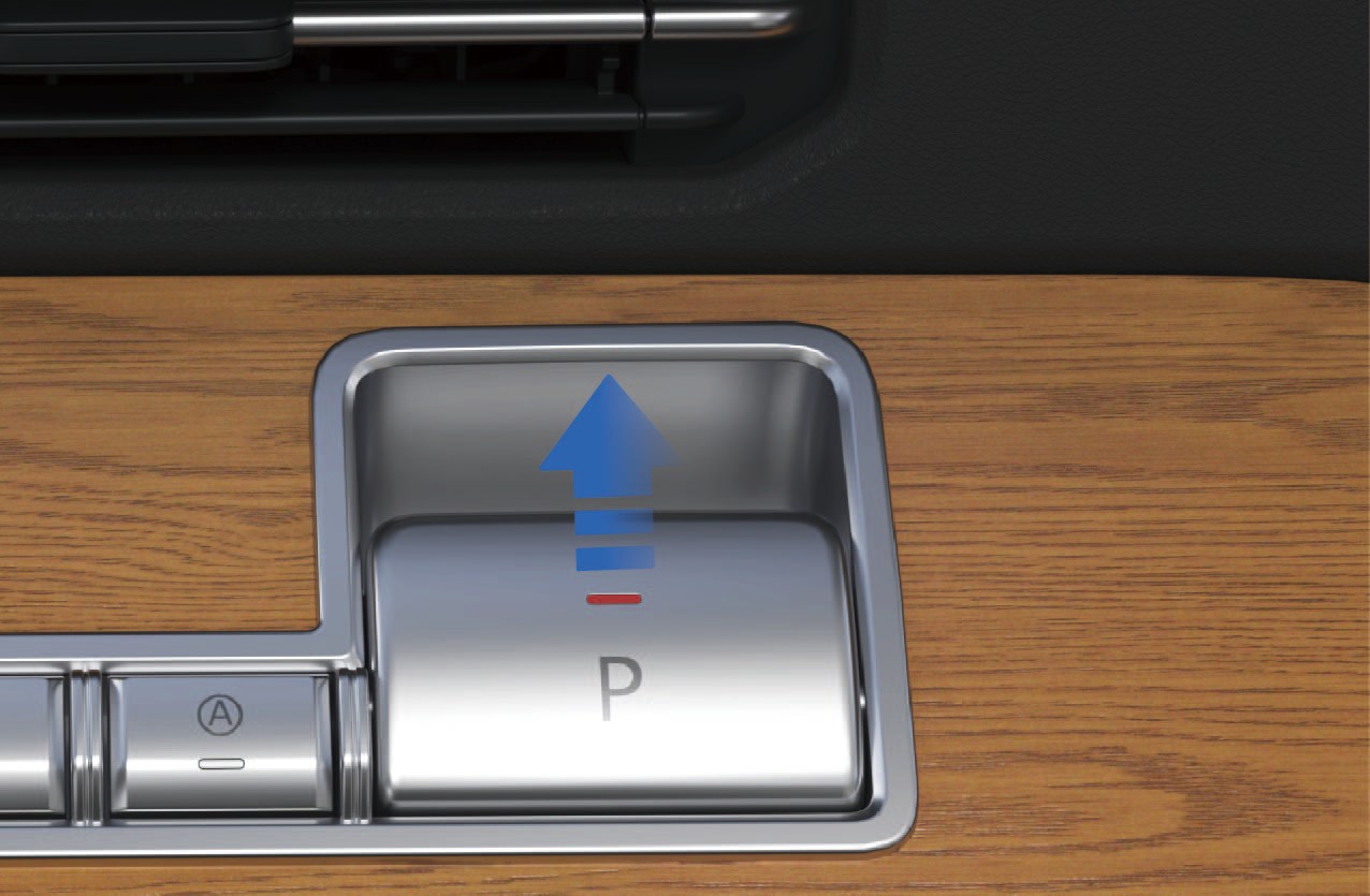 Operating instructions
For EPB electronic parking, it can be used as an emergency braking operation when the service brake fails. When EPB applies emergency braking, when the vehicle speed drops to 3 mph, the system will directly activate the parking brake and maintain the parking state. Moreover, the parking brake cannot be automatically released when the vehicle starts, and can only be released manually by operating the EPB parking brake switch.
↑ TopWhen you need emergency braking, pulling up the EPB parking brake switch can achieve emergency braking. The greater the
Shift Operation
↑ Top
Driving
opening of the pull up switch, the greater the braking force applied.
Precautions
Warning
If the vehicle speed is high, the parking handle should be pulled in a similar way as a "spot brake". Do not tighten or lock it all at once to avoid damage to the brake and other related components and loss of braking efficiency.
↑ TopYou can shift gears by using the shift lever on the right side of the steering wheel.
Operating instructions
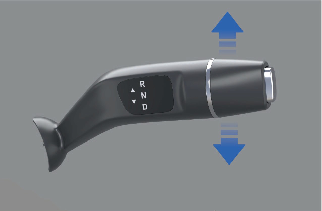
R (reverse) gear
When the vehicle is stationary, depress the brake pedal and push up the shift lever, then the instrument cluster will display "R" gear, indicating that the vehicle has been put into R gear.
N (neutral) gear
When the shift lever is in "R" gear, push the shift lever down by 1 gear and hold for 1 second.
When the vehicle is in EPB mode, depress the brake pedal and release the EPB.
D (drive) gear
↑ TopWhen the vehicle is stationary, depress the brake pedal and push down the shift lever simultaneously, and the instrument cluster will display "D" gear, indicating that the vehicle has been put into D gear.
If the gear shift fails, the instrument panel will prompt the reason for the gear shift failure, and the text prompt includes: please press the brake to shift, please READY before shifting, or please stop and shift; If the gear shift is successful, there will be no text prompt.
Precautions
↑ TopNoticeThe vehicle must be powered off in N gear, and it is forbidden to directly power OFF and stop the vehicle in D or R gear.
The vehicle can be engaged in N gear with "N" gear indicator
highlighted in the instrument cluster through the following operations:
When the shift lever is in "D" gear, push the shift lever up by 1
gear and hold for 1 second.
Regenerative Braking
↑ TopDriving
Turn the left paddle of kinetic regenerative braking system (KERS) to reduce the kinetic regenerative braking intensity of the vehicle during coasting.
2. Kinetic regenerative braking paddle (right)
During driving, you can improve the driving experience by adjusting
the regenerative braking level, which can reduce the loss of brake heat, thereby improving energy efficiency.
Operating instructions
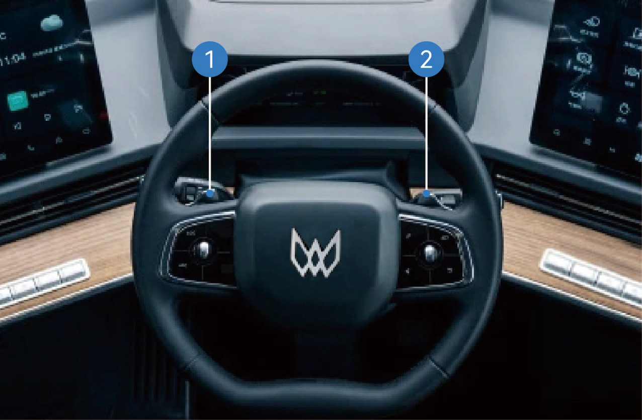
Kinetic regenerative braking paddle (left)
↑ TopTurn the right paddle of kinetic regenerative braking system (KERS) to increase the kinetic regenerative braking intensity of the vehicle during coasting.
During driving, the coasting energy is recovered when the accelerator pedal and the brake pedal are released. The braking energy will also be recovered when the brake pedal is depressed. You can adjust the regenerative braking intensity during coasting through the KERS paddles on the left and right sides of the steering wheel.
The lower right corner of the instrument cluster will show the current regenerative braking level (level-1, level-2, level-3, level-4 and level-5). When the regenerative braking level is set to 0, the regenerative braking function of the vehicle will be turned off.
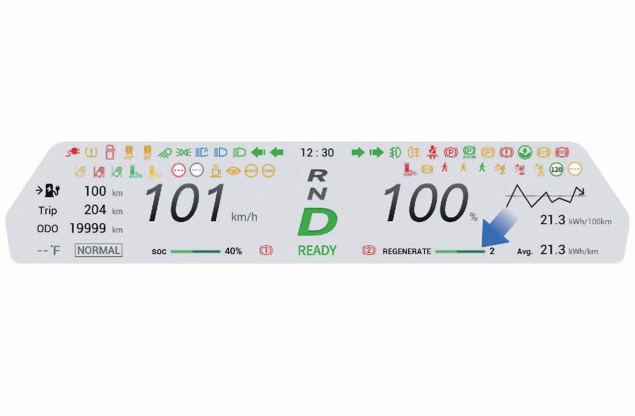
Precautions
Notice
Regenerative braking is not a substitute for braking to ensure safety. You should apply the brakes in time according to the actual situation.
Avoid using the regenerative braking function in rainy or snowy weather or on slippery roads.
↑ TopNoteWhen the battery level of the vehicle drops below 95%, you can turn on and apply the regenerative braking function.
AR-HUD*
↑ TopDriving
The AR-HUD can project vehicle-related information onto the front windshield so that it is easier for you to obtain legible information rapidly while driving, thus improving driving safety.
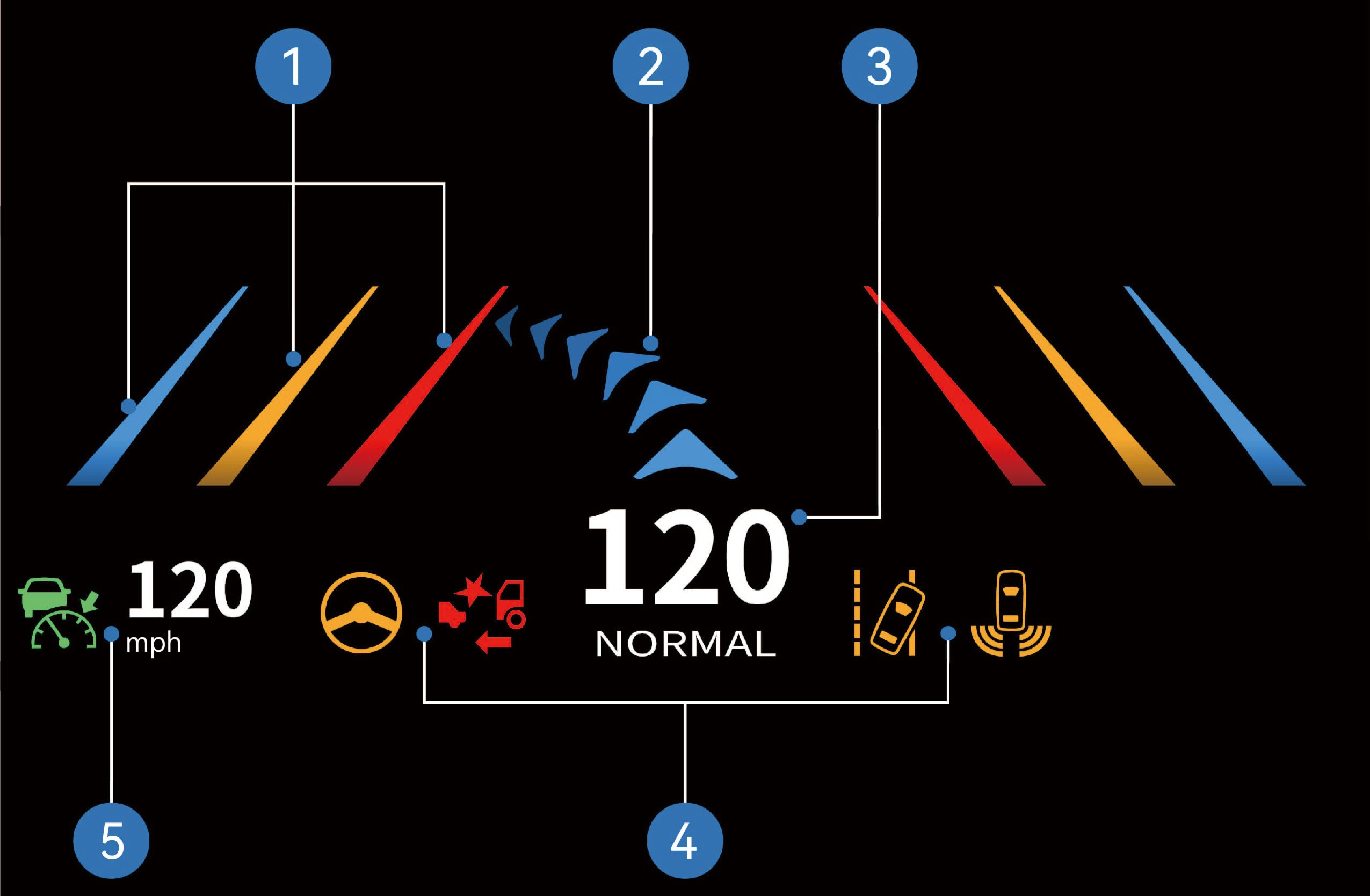
Lane departure line prompt
Navigation arrow
Driving speed + driving mode
Instrument cluster warning icon
ACC status icon + cruise speed
Operating instructions
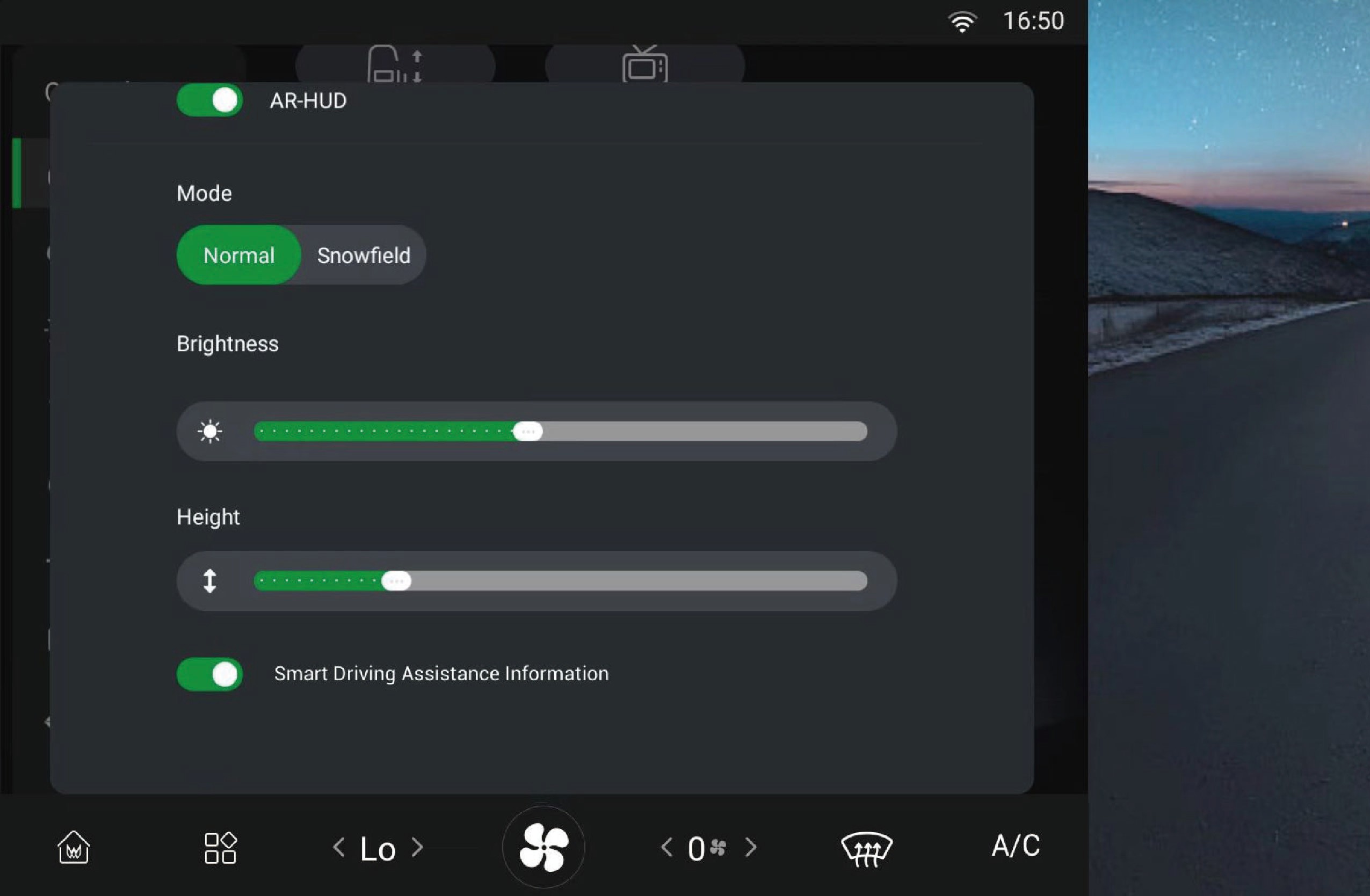
↑ TopYou can select "Control Center", switch to "Inside" interface, and click "AR-HUD" button on the vehicle information screen to enter the interface where you can turn on/off the function, and adjust the display mode, brightness, height and display information according to your personal preferences.
Precautions
Warning
Before driving, make sure to check that the position and brightness of the AR-HUD will not interfere with safe driving. Improper adjustment of the image position or brightness may obstruct your field of vision and cause an accident, resulting in personal injury.
Do not keep looking at the AR-HUD while driving, otherwise you may not be able to notice pedestrians and objects on the road in front of the vehicle.
Notice
Do not allow liquids to enter the projector area as this may cause AR-HUD failure.
Do not place any objects or stickers on the projector or the projection area of the windshield, otherwise the AR-HUD may not function properly.
If the seat is high, your head will be in a high position and you will not be able to see the display. You can lower the AR-HUD to a suitable height.
Differential Lock
Driving
↑ TopWhen driving on muddy and slippery roads or when climbing under heavy loads, the drive wheels may slip or it may be difficult for the vehicle to move. In this case, you can use the vehicle differential lock to improve the passability of the vehicle.
Note
When driving on snowy roads, switch to snow mode to prevent the AR-HUD image from interfering with the driving vision.
Operating instructions
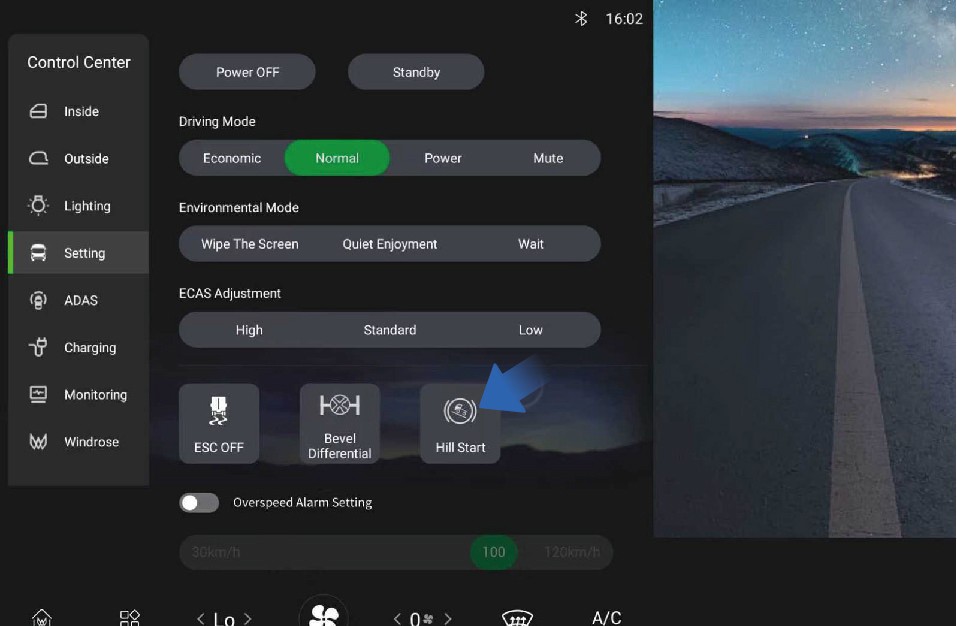
↑ TopYou can select "Control Center", switch to "Setting" interface, and click "Bevel Differential" button on the vehicle information screen, then the switch will be highlighted and the differential function will
be turned off; When the switch is highlighted, click the "Bevel Differential" button again, then the switch will turn gray and the differential function will be turned on.
Precautions
Warning
The differential lock is only applicable to situations where the wheels are slipping or the vehicle is trying to get out of trouble. Do not run for a long time with the lock engaged.
The vehicle should not make turns after the differential lock is engaged. Otherwise it will cause damage to the differential and other parts.
After the vehicle passes through poor road conditions, release the differential lock immediately. When the vehicle speed is ≥ 3 mph, it is strictly forbidden to use the differential lock.
Driving Mode
↑ TopDriving
You can select the drive mode by selecting "Control Center" and switching to the "Setting" interface on the vehicle information screen of the instrument panel to tailor your needs.
ECO mode
This vehicle has three driving modes, which offer you the chance
to choose how you want to drive. Each mode provides a different driving experience.
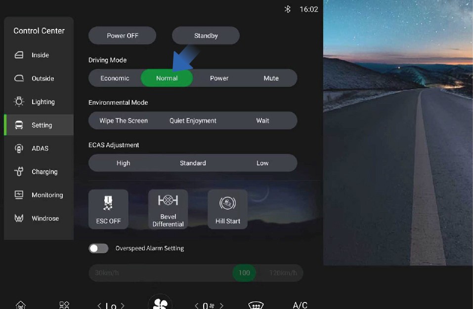 Operating instructions
It can effectively reduce the energy demand for the high-voltage battery to achieve economical driving; When the battery SOC is lower than 10%, the vehicle automatically enters ECO mode.
Normal mode
It can offer a good balance of power and economy, which can meet the daily needs of most drivers.
Power mode
↑ TopIt can provide the designed maximum power output of the vehicle and require the drive motor to respond as quickly as possible to achieve optimal output torque and strong power performance with higher energy consumption.
Around View Monitor (AVM)
Driving Assistance
↑ TopThe around view monitor (AVM) uses cameras installed around the vehicle to capture images, and the AVM module stitches and synthesizes the high-definition image signals collected by the cameras to achieve 2D/3D panoramic view. The area not covered by the panoramic view can be supplemented with the image from the rear camera.
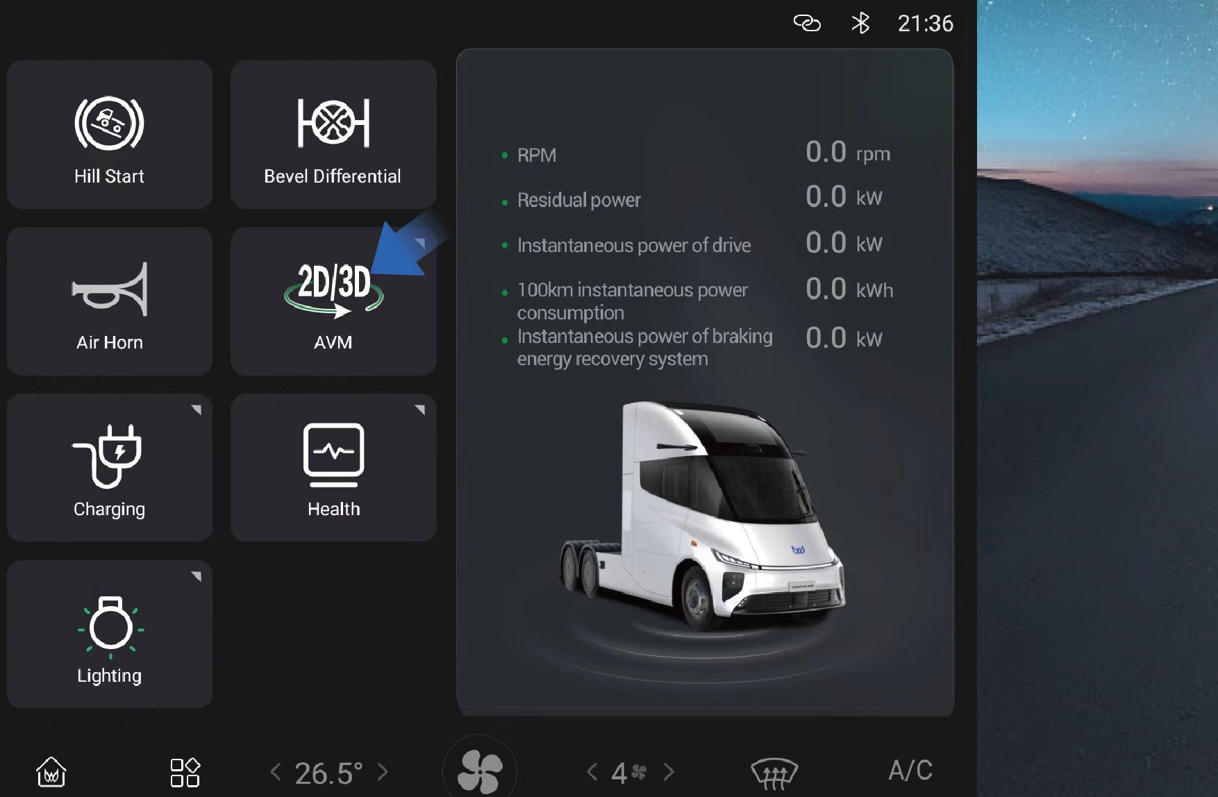 Operating instructions
You can set and adjust the AVM function by selecting "Home" and clicking the "AVM" button on the vehicle information screen of the instrument panel.
Parking assist (PA)
Parking assist can monitor the surrounding conditions of the vehicle when the vehicle is reversing at low speed to ensure driving safety. During parking, the vehicle will alert you with warning sounds and images based on the distance between the obstacle and the front or rear of the vehicle.
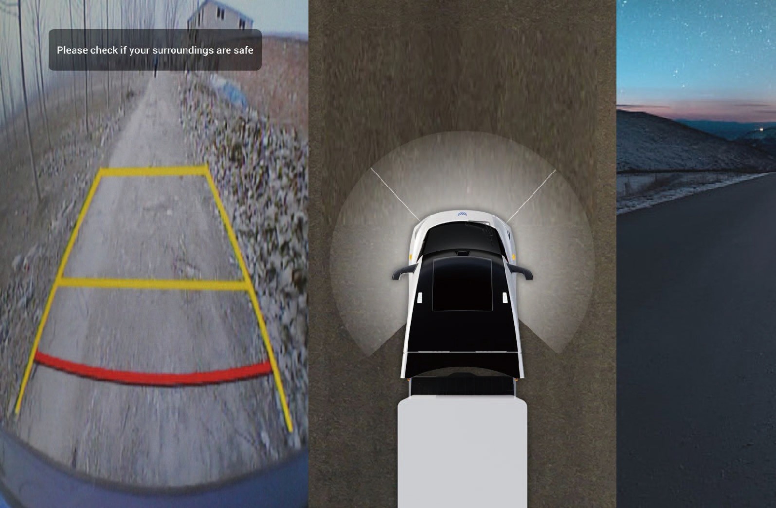
You can activate the parking assist image in the following ways:
On the home page of the vehicle information screen, click AVM to turn on the 270° panoramic image;
When the vehicle is engaged in R gear, the memory view (270° panoramic image) will be turned on.
↑ TopReverse camera vision system (RCVS)
The RCVS system provides the driver with a rear view during vehicle reversing, improving safety during the reversing process.
Shifting to reverse gear will enter the interface.
Precautions
NoticeThe reverse image relies on the rearview camera sensor to operate normally. The following situations may cause the sensor to be limited and the camera function to be restricted:
• Camera installation position change, obstruction or dirt, defocusing or malfunction, etc.
The surrounding environment is dim, such as at dawn, dusk, night, in tunnels, buildings, and near large vehicles casting large shadows.
Sudden changes in ambient brightness, such as at tunnel entrances or exits.
Adverse weather conditions such as rain, snow, fog, and haze.
Moving Off Information System (MOIS)
↑ TopDriving Assistance
The MOIS system can monitor pedestrians/bicycles in blind spots ahead of the vehicle and operates effectively at low speeds to prevent collisions with pedestrians or cyclists. When the MOIS system detects the presence of pedestrians or cyclists in front of the vehicle, it can inform the driver through a combination of visual and audible signals to ensure that the driver can take timely measures.
When the vehicle is stationary, the instrument panel will trigger a visual alarm if a pedestrian enters the front danger zone. If the vehicle is moving forward and a pedestrian enters the front danger zone, the instrument panel will activate both audible and visual alarms until the pedestrian leaves the danger zone.
When the sun is at a low angle or shining directly on the camera.
Operating instructions
You can switch to the "ADAS" interface by selecting "Control Center" from the car infotainment screen on the right side of the dashboard, clicking the "MOIS" button to turn on/off the MOIS function, and synchronizing by selecting "MOIS Alarm Sound" to turn on and off the MOIS alarm sound.
MOIS system fault alarm
If there is an error/malfunction in the system, a fault warning signal will be displayed on the dashboard, which may cause the following faults:
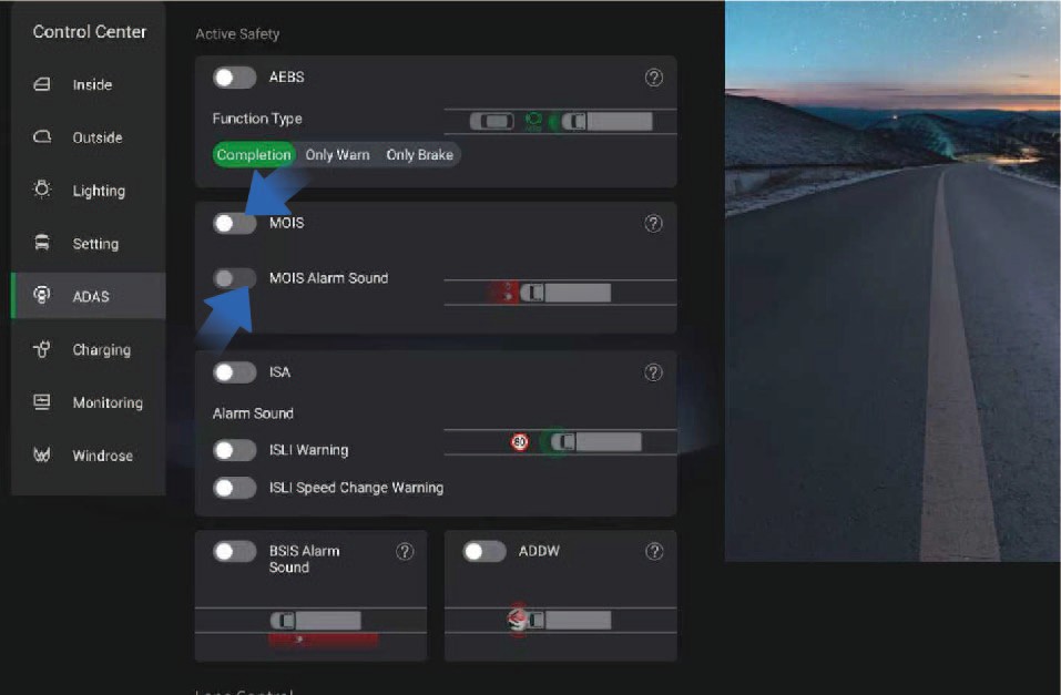
After being completely covered by ice, snow, mud, soil or similar substances, the obstruction can be detected and the function will be automatically turned off, and a fault signal will be sent to the driver to indicate the obstruction status. When the obstruction is removed, the function should return to normal.
The system detects the ambient light intensity, automatically shuts down when the ambient light intensity is below 15 lux, and notifies the driver of this status with a fault signal. After the ambient light returns to normal, the function returns to normal.
When the MOIS system malfunctions due to hardware, software, or interactive component failures, relevant signals are used to alert the driver of the system's fault status.
Adaptive Cruise Control (ACC)
↑ TopDriving Assistance
The adaptive cruise control (ACC) is a driver assistance function to improve the driver's comfort. If the road ahead is clear, the ACC will maintain the set maximum cruising speed and allow the
vehicle to drive forward. If a vehicle is detected ahead, the ACC will reduce the speed of the subject vehicle as needed to maintain the set following distance from the vehicle ahead until the appropriate cruising speed is reached.
With ACC activated, you still need to observe the road conditions ahead and control the vehicle when necessary. The ACC is mainly used for driving on dry straight roads such as highways. It is not recommended to activate the ACC when driving on city streets.
Operating instructions
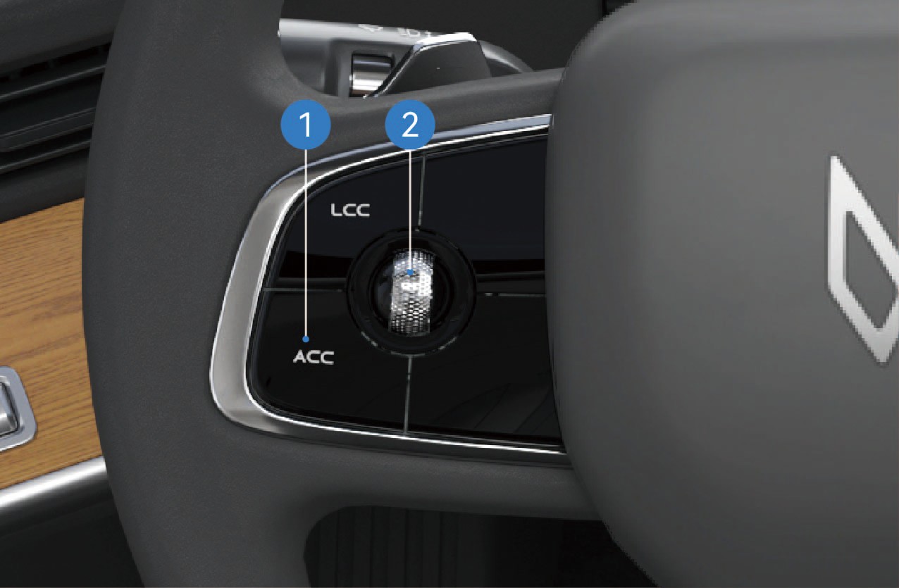
ACC ON/OFF
Click the button to turn on the ACC, and the ACC ON indicator will be illuminated in gray on the instrument cluster. When the ACC working conditions are met, the indicator will be illuminated in green, the ACC function will be activated, and text prompt and numerical information such as cruising speed will be displayed.
In cruise mode, click the button to turn off the ACC, the indicator will turn gray and text prompt will be displayed on the instrument cluster.
Cruise control scroll wheel
Right: Increase the following distance.
Left: Decrease the following distance.
Up: Increase the vehicle speed.
Down: Decrease the vehicle speed.
Slide the cruise control scroll wheel up or down and release it to gradually increase or decrease the target speed by ±1 mph; Slide the cruise control scroll wheel up or down and hold it to gradually increase or decrease the target speed by ±3 mph. Operate the distance button to change the following distance (five levels in total).
With ACC on, if you slide the cruise control scroll wheel down,
the system will set the current vehicle speed as the cruising
speed; If the brake pedal is depressed or the cruise switch is pressed during ACC activation or the vehicle speed does not meet the ACC activation conditions , causing ACC to deactivate, the system will memorize the previously set cruising speed when the ACC is successfully activated again and the cruise control scroll wheel is moved up.
When the vehicle is powered on for the first time, the following distance defaults to level 3. In the same power-on cycle, the last set following distance level will be memorized at the time of reactivating ACC, and the default level (level 3) will be maintained when the vehicle is powered on again.
Description of ACC function status
Cruise control
When there is no target vehicle ahead or the target vehicle speed is greater than the target cruising speed, the cruise control will keep the vehicle driving at the target cruising speed.
Following control
The following control function allows the vehicle to follow the vehicle ahead at the following distance set by the driver.
Overtaking mode
With ACC activated, when the driver depresses the accelerator pedal, the ACC will enter the overtaking mode; If the driver releases the accelerator pedal within 15 minutes, the vehicle will return to the target speed.
Driver takeover request
In certain scenarios, the ACC is unable to keep the vehicle driving at a safe distance and it will send a signal to prompt the driver to take over the vehicle. In this case, the icon on the instrument cluster will be illuminated, and an audible alarm will be given, reminding the driver to take over the vehicle.
Curve speed control
The curve control logic is that when the vehicle follows the vehicle ahead or cruises at a constant speed in a curve, the ACC will control the vehicle speed based on the curve radius to keep the lateral acceleration within a comfortable range.
Camera and radar recognition failure
In the following situations, the camera recognition failure may occur, affecting ACC performance, and even causing the function deactivation with the text prompts displayed in the instrument cluster, including but not limited to:
The camera mounting position is changed.
The camera is obscured or dirty.
The vehicle is driving at night.
The surroundings are dim, such as at dawn, dusk, and night or in the tunnel.
The brightness of the surrounding environment changes suddenly, such as entrance or exit of a tunnel.
Large shadows caused by buildings, landscapes or large vehicles.
The camera is exposed to direct light.
In bad weather such as rain, snow, fog, haze, etc.
Exhaust fumes, splashes of water, snowflakes or dust raised by the vehicles in front falling on the subject vehicle.
The windshield in front of the camera is contaminated by water, dust, micro-scratches, oil, dirt, wiper, freezing, snow, etc.
The vehicle is driving on a wet road.
In the following situations, the radar recognition failure may occur, affecting ACC performance, and even causing the function deactivation, including but not limited to:
The radar is misaligned or blocked, or covered with mud, snow, metal plate, tape, label, leaves, etc.
The radar or the surrounding area is impacted due to vehicle collision or scratching.
Adverse weather conditions such as heavy rain, heavy snow, and heavy fog may affect the performance of radar.
Limited by characteristics of the object identified, the sensor may issue false alarms with regard to some metal fences, green belts, cement walls, etc., in few cases.
ACC can only identify qualified vehicles. The following targets may fail to be identified and may be responded to, including but not limited to:
Side passing vehicles.
Oncoming vehicles.
Bicycles, motorcycles, tricycles, etc.
The ACC cannot identify the following targets, including but not limited to:
Person.
Animal.
Traffic light.
Walls.
Barricades
Other non-vehicle objects.
The ACC may work or respond too late in the following situations where the target is not directly located in front, including but not limited to:
The ACC cannot identify targets in the blind spot of the sensor. For example, the ACC cannot identify the objects in the corner and side blind spots of the vehicle. When approaching or passing a curve, it may select a wrong target or miss the target, causing the vehicle to accelerate or decelerate.
When the vehicle is on a slope, the target may get lost or the distance from the vehicle ahead may be misjudged. When the vehicle going downhill, the ACC may increase the vehicle speed, resulting in exceeding the cruising speed.
The ACC may not be able to recognize in time if the vehicles (especially large vehicles such as buses and trucks) in the adjacent lane cut from the front of your vehicle with only part of the vehicle body. At this time, you shall override the vehicle in time.
The ACC may not be able to recognize the target in time if your vehicle suddenly cuts behind the vehicle in front, or if another vehicle suddenly cuts into or out of front of your vehicle. At this time, you shall override the vehicle in time.
In special or complex road conditions, it is not recommended to use ACC, as it may be affected or even deactivated, including but not limited to:
Waterlogged, muddy, potholes, ice and snow roads, or roads with speed bumps or obstacles.
Traffic conditions with pedestrians, bicycles, or many animals.
Complex and changeable traffic conditions, such as busy intersections, highway ramps, and congested roads.
Winding roads, sharp turns.
Uphill and downhill roads.
Bumpy roads.
Narrow roads.
Tunnel entrances and exits.
Non-standard roads.
Roads without median strips.
In the following situations, if the relative speed of the vehicle ahead is too high, the ACC may have limited controllability, resulting in failure to keep the distance in time: Including but not limited to:
The status of the vehicle ahead changes suddenly (such as sudden turning, acceleration, deceleration, etc.).
Other vehicles suddenly cut in or out of the subject vehicle.
The subject vehicle suddenly cuts in behind the vehicle ahead.
The subject vehicle is moving at high speed to a stationary or slow-moving target in front.
Sufficient braking force may not be obtained in the following situations. Including but not limited to:
The braking function cannot work normally (such as brake parts are too cold, too hot, wet, etc.).
The vehicle is maintained improperly (such as excessive wear of brakes or tires, abnormal tire pressure, etc.).
The vehicle is driving on special roads (such as uphill and downhill, water flooded roads, mud, potholes, icy and snowy roads, etc.).
Exit conditions of ACC
In any of the following situations, the ACC will be deactivated immediately:
Any door is open;
The driver seat belt is unfastened;
The vehicle is not in D gear;
The brake pedal is depressed;
The EPB is applied;
The vehicle is not powered on;
The ESC is deactivated;
The wheel speed signal is invalid;
The vehicle speed is not within the specified speed range;
The AEB works;
The radar/camera is blocked;
Other system errors have occurred.
In any of the following situations, the ACC will be gradually deactivated:
The ESC is activated;
The ABS activation time is greater than 2 seconds;
The ASR is activated;
The ACC off button is pressed.
Precautions
Warning
If you are aware of a danger while using the ACC, please take over the vehicle immediately instead of waiting for the system warning prompt.
For stationary vehicles or objects, especially those appeared after the vehicle ahead drives away your lane, the ACC will not be able to recognize them and apply brakes or slow down. You should always pay attention to the road conditions ahead
and be ready to take over the vehicle at any time. Relying
solely on ACC may cause personal injury or even death. In addition, the ACC may react to vehicles or objects that do not exist or are not in the lane you are driving, causing unnecessary or inappropriate deceleration of the vehicle.
The ACC may not control the vehicle speed properly due to limited braking capacity and being on a slope. It may also misjudge the distance between the subject vehicle and the vehicle ahead. When the vehicle is going downhill, the ACC may increase the vehicle speed, resulting in exceeding the cruising speed (or limit speed).
Do not rely solely on ACC to slow down the vehicle and avoid a collision, otherwise, serious personal injury or death may occur. Always observe the road conditions while driving and be ready to take over the vehicle at any time.
The ACC is only a driver assistance function, which can not prevent all collisions. The ACC has a limited deceleration capability and cannot replace the driver in driving. It is always your responsibility to drive your car safely and to obey current laws and traffic regulations.
The ACC can adjust the vehicle speed smoothly based on vehicle conditions and traffic conditions ahead. However, due
to the limitations of the monitoring system, the system may fail
to apply brake in an emergency. When necessary, you should take the initiative to take braking actions.
The ACC cannot be applied in all driving scenarios and traffic, weather and road conditions.
You must intervene when the ACC fails to maintain a proper speed or distance from the vehicle ahead. It is your responsibility to determine and maintain a safe following distance at all times. Do not rely solely on ACC to maintain the distance between vehicles.
The ACC may not respond to animals, pedestrians, specially- shaped vehicles, vehicles loaded with irregularly shaped cargo, or small vehicles (such as bicycles, tricycles, and motorcycles) or traffic signs (such as traffic cones, water-filled barriers, signboards). ACC may also not respond to slow- moving, stopped or approaching vehicles, or other stationary objects.
The ACC may cause abnormalities such as excessive deceleration and deceleration shock due to the asynchronous response of the electronic brake system (EBS) between the trailer and the tractor unit. In this case, please deactivate ACC.
Do not use the ACC in environments with poor driving
conditions, such as: in the city or other heavily congested
traffic, roads with water or slush, heavy rain and snow, poor visibility, windy conditions, or driving on slopes.
Loading too many items may cause a change in vehicle attitude, which may degrade or disable the target identification of ACC.
When another vehicle changes lanes to the front of your vehicle, ACC may not have time to respond, requiring you to apply braking in time.
When driving downhill on steep slopes, it may be difficult for ACC to maintain proper distance from the vehicle ahead. In these situations, be extra careful and always be ready to apply braking.
When you are driving into and out of curves, the selection of a target may be delayed or interfered, which may cause ACC to brake unexpectedly or brake too late.
On a sharp turning road, such as a serpentine road, the ACC may not be able to detect the vehicle ahead normally due to the limited field of view of the windshield and front radar, in which case, the vehicle may accelerate, which requires you to take over the vehicle according to the actual situation.
At night with insufficient lighting or in a city with complex lighting, the camera may misidentify, miss, or inaccurately
identify the target, causing ACC to brake incorrectly or brake too late. You need to use the ACC function with caution, stay focused, and be ready to take over the vehicle at any time.
If you need to cut out of the current lane or the vehicle ahead cuts out while following the vehicle ahead, the ACC may be limited in acceleration for a period of time to ensure safety. You can actively depress the accelerator pedal to take over the vehicle.
NoticeAfter the ACC is deactivated, you must override the vehicle to ensure the driving safety.
Note
When the following target is changed or lost (especially during turns or lane changes), the ACC may accelerate unexpectedly.
When the vehicles, objects or stationary targets in adjacent lanes are changed or lost (especially during turns or lane changes), the ACC may brake unexpectedly.
The ACC is mainly suitable for driving on smooth roads. When
ACC is used for driving downhill on steep slopes or with heavy
loads, it may be difficult to maintain the correct following distance from the vehicle ahead.
The ACC can control your vehicle to accelerate and decelerate. When the vehicle is decelerating, the brake system starts to work and may make a sound, which is normal.
When the ACC fails, a text prompt will be displayed on the instrument cluster to remind the driver that ACC is faulty.
When the vehicle speed is 0, the system will automatically turn off the prompt sound.
If the vehicle speed gradually increases, the prompt sound volume will gradually decrease until it is automatically turned off; If the vehicle speed gradually decreases, the prompt sound volume will gradually increase.
When the vehicle is in reverse gear (R gear), the reverse prompt sound is activated, and the prompt sound is "beep beep beep".
Low Speed Alarm And Reverse
↑ TopReminder Device
Driving Assistance
This car is equipped with a low-speed alarm and reverse reminder device, which will alert surrounding personnel and vehicles when you are driving at low speed or reversing.
Reversing status
When the vehicle speed is reduced to the specified range, the vehi- cle turning sound alert device will be activated.
When the vehicle is driving at low speed, the prompt
↑ Topsound is "ding-ding-ding".
Automatic Emergency Braking (AEB)
↑ TopDriving Assistance
The automatic emergency braking (AEB) system can detect target vehicles or obstacles, predict a risk of potential forward collision, and send a warning signal and display the image on the vehicle information screen in case of a danger to remind the driver and activate the brake system of the subject vehicle to avoid or
mitigate collisions by reducing speed.
AEB function
Safe distance alarm
In non-emergency situations, the system will remind the driver that the distance between the subject vehicle and the vehicle ahead is too small, sound the buzzer at a low frequency, and highlight the prompts in green on the simulated reality system.
Level 1 warning
When a dangerous situation occurs, the system will remind the driver that actions should be taken to respond to the level 1 warning, sound the buzzer at a low frequency, and highlight the prompts in yellow on the simulated reality system.
Level 2 warning
In the case of an emergency, the system will remind the driver that actions should be taken to respond to the level 2 warning, sound the buzzer at a high frequency, and highlight the prompts in red on the simulated reality system.
Emergency brake
After the collision alarm is issued, if the driver still does not take measures, AEB will actively apply the brake braking force, increasing the driver's reaction time and reducing the relative speed.
System fault
When the system fails, a text prompt will be popped out, the AEB switch in the vehicle information screen will be in the off position and the icon will be grayed out, indicating that the function is unavailable.
Operating instructions
AEB activation
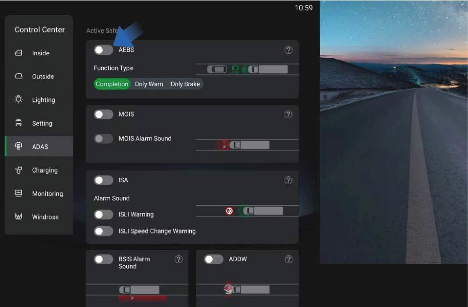
You can activate/deactivate this function by selecting "Control Center", switching to "ADAS" interface, and clicking the "AEBS" button on the vehicle information screen of the instrument panel.
The AEB is activated by default after the vehicle is powered on. When this function is deactivated manually, the system will display the corresponding text prompt on the vehicle information screen. When the AEB fails, the system will display the corresponding text prompt on the vehicle information screen, and the AEB icon will be grayed out, indicating that the function is unavailable.
Applicable scenarios of AEB
The AEB can detect the pedestrians, two-wheeled vehicles, passenger cars, trucks, and etc., except for oncoming vehicles and crossing vehicles. If the visual detection capability is limited, the AEB will give a warning for moving targets, but will not apply brakes. (Note: When the vehicle is driving through curves, the AEB will give a warning but not apply brakes to the detected pedestrians and two-wheeled vehicles).
Limitations of AEB
The function will be limited in the following situations:
The AEB can assist the driver in dangerous situations, but the driver should not solely rely on the system.
In adverse weather conditions, such as heavy rain, snow, etc., the function will be degraded, and cannot detect the target or
detect the target too late.
The AEB is running in the background under normal conditions and will not be noticed by the driver. Therefore, if the relevant targets are detected by the system, they will not be displayed.
The AEB may be triggered by mistake due to its limitations.
Please note that the sensor cannot detect dangerous obstacles ahead in all situations.
Certain targets can weaken and block radar detection, such as highway guardrails, tunnel entrances, heavy rain or snowy weather, thus affecting the AEB.
In some scenarios, only radars or cameras detect objects, and the system cannot achieve optimal performance, and such system performance degradation will not be perceived by the driver.
The AEB is designed to detect moving targets in the same lane and direction in normal traffic conditions. When certain conditions and speed ranges are met, the AEB system can also detect stationary targets in the lane where the subject vehicle is driving.
The system will not respond to animals, oncoming and crossing vehicles.
For safety reasons, the implementation of the AEB function requires the support of the ESC system.
The AEB can only respond to a target that is in the detection range of the radar sensor and has been identified. For cut-in targets, targets that are detected after the subject vehicle changes lanes, and those on sharp turns, the performance of AEB will be greatly limited.
If the radar is affected by strong vibration or slight impact during calibration, the system performance will be reduced and the false trigger rate will be increased. Therefore, the radar needs to be checked for the installation position or to be re- calibrated.
The radar system requires special performance to detect relevant targets. When affected by the environment such as under electromagnetic interference or by the target itself, the detection will be disturbed and the system performance will be reduced.
The radar system is installed in front of the vehicle, and no other obstacles are allowed in the field of view of the radar sensor. In the installation position, the radar will be affected by dust and snow. When the radar is completely covered by snow, the system may be turned off. In this case, the driver will be informed of relevant information through the IVI interface.
The target will not be detected until it appears in the detection range of the sensor; When the target changes lanes or cuts in too close, the system may not detect the target in front.
Targets that cannot be clearly identified, such as motorcycles or bicycles, and vehicles with high driving positions are often detected too late or cannot be detected.
Precautions
Warning
The driver is responsible for safe driving without dangerous situations.
AEB is only a driver assistance system and cannot exempt the responsibility of the driver to drive the vehicle safely. The driver must be fully responsible for all traffic scenarios.
Even if the traffic conditions are not very dangerous, AEB may still give alarms and apply brakes, such as power loss of vehicle ahead, overtaking, or passing through curves, so the driver must be ready to take over the vehicle at all times.
AEB cannot avoid all accidents in all traffic scenarios.
AEB cannot respond to oncoming vehicles, animals, and crossing vehicles.
When the AEB system fails or the system cannot work properly, please go to a Windrose authorized service center for repair immediately. Do not modify it without authorization.
The braking performance of AEB depends on the braking system of the vehicle.
When the ESC/EBS MIL is on, the AEB system will not work properly. Check and troubleshoot related faults in time.
Do not use AEB when the vehicle is being towed, the vehicle is placed on a drum bench, the vehicle is driving on a sloped curve, or the radar camera is blocked or obscured by the deformed components.
Electronic Braking System (EBS)
↑ TopDriving Assistance
The electronic braking system (EBS), as a control system upgraded from the ABS and ESC, can reduce the response time and pressure building time of the braking system, realize the
electronic brake force distribution of the vehicle and the consistency control of the tractor unit and trailer, shorten the braking distance and improve the overall braking performance of the vehicle. The EBS integrates functions such as ASR, HSA, and ESC.
Precautions
↑ TopWarningWhen the EBS fails, the yellow EBS MIL will be illuminated on the instrument cluster. Contact the Windrose authorized service center as soon as possible to inspect and repair the system.
Electronic Brakeforce Distribution (EBD)
↑ TopDriving Assistance
Function introduction
↑ TopElectronic Brakeforce Distribution (EBD) ensures good braking performance and stability of the vehicle under different load conditions by regulating the distribution of braking forces between front and rear wheels and controlling the slip of rear wheels.
Acceleration Slip Regulation (ASR)
↑ TopDriving Assistance
The acceleration slip regulation (ASR) is an electronic system that monitors and controls the driving force of the driving wheels during driving on the basis of ABS. If the system detects vehicle slipping when accelerating or starting, the ASR will be activated to brake the slipping wheels so as to maintain the stability in driving direction and the starting ability of the vehicle.
Lane Departure Warning (LDW)
↑ TopDriving Assistance
When the vehicle deviates from the current lane unconsciously, the lane departure warning (LDW) will alert the driver with visual and audible alarm sounds.
Activation conditions of LDW
LDW may be restricted or not work normally under the following circumstances, including but not limited to:
The operating speed is outside the normal operating speed range (37–75 mph).
The vehicle is affected by crosswinds.
The vehicle is driving on a slope.
The vehicle is driving through a road with sharp curves.
The vehicle is extremely inclined under heavy loads or abnormal tire pressure.
The vehicle is driving on roads that can result in great amplitude of oscillatory motion in the vehicle, or on road surfaces with a large number of road joints.
The vehicle is driving on roads without lane lines, or with unclear lane lines or disordered lane lines due to construction.
The following distance is too close to detect the lane lines.
The imaging capability of the camera is affected. Including but not limited to the following situations:
Poor visibility at night.
Poor visibility due to bad weather, such as heavy rain, heavy snow, fog, dust.
Bright light, backlight, water reflection, or extreme light
contrast.
The camera is blocked by dirt, ice, snow, etc.
The performance of the camera deteriorates under high temperatures, extreme cold weather and other extreme weather.
Operating instructions
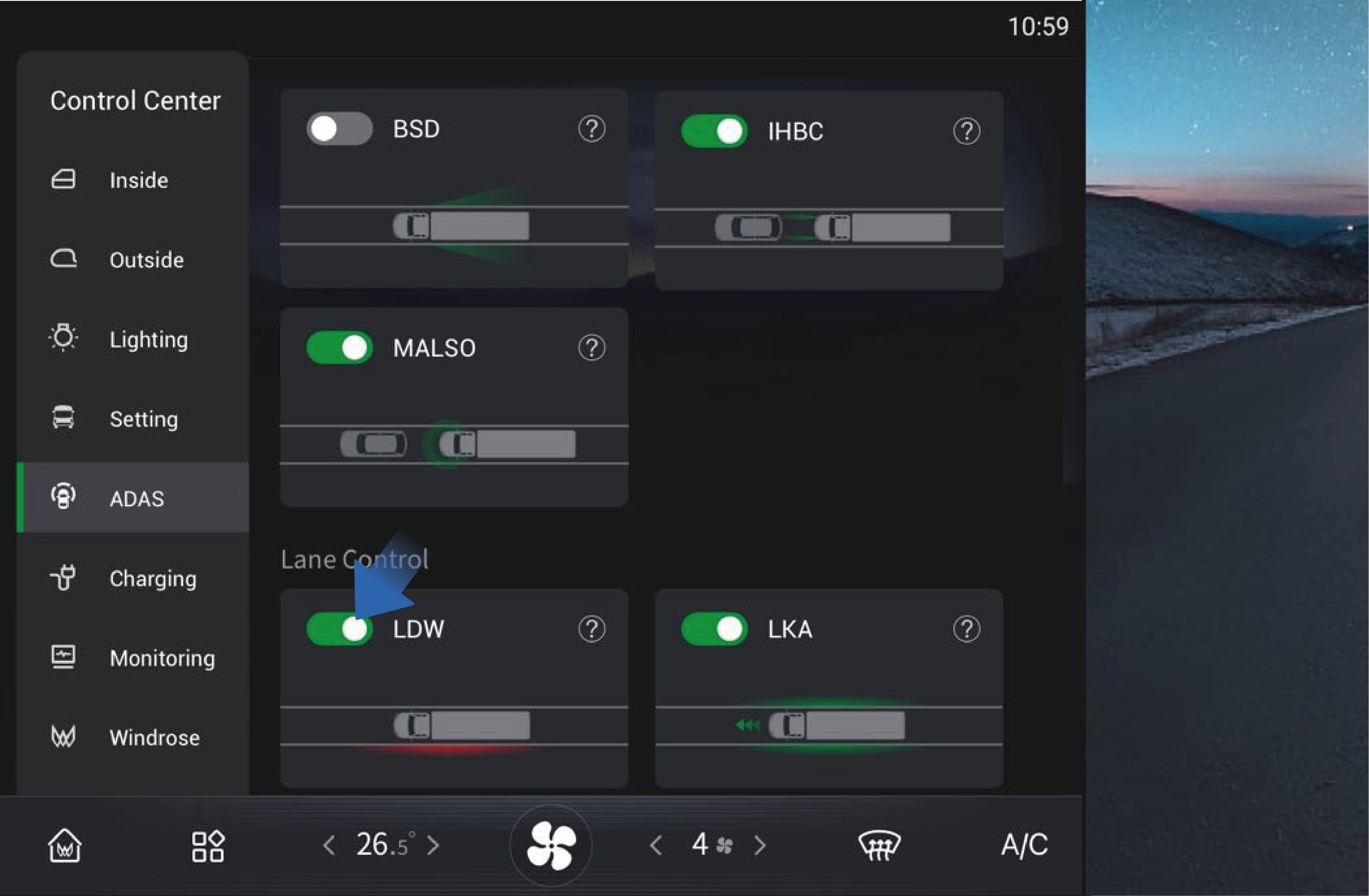
↑ TopYou can activate/deactivate the function by selecting "Control Center", switching to "ADAS" interface, and clicking "LDW" button on the vehicle information screen of the instrument panel.
LDW is enabled by default when powered on, and you can
manually disable it as needed.
Precautions
Warning
LDW is a driving assistance function, and it cannot replace your observation and judgment of traffic conditions and the driver's responsibility for safe driving.
Do not use LDW at road forks, conjunctions, etc.
Do not use LDW when snow chains are used in the vehicle.
Do not use LDW when the tires are excessively worn or the tire pressure is too low.
Do not use LDW when mixing tires of different constructions, or brands or from various manufacturers, or having diverse tread patterns.
Do not use LDW when the vehicle is driving on construction roads (with construction signs, cone barrels, etc.).
Do not use the LDW in poor driving conditions, such as sharp
turns, steep slopes, icy and slippery roads, or in bad weather such as rain, snow, fog.
You should maintain attention and judgment at all times, ensure that the vehicle is in its own lane, and comply with current laws and traffic regulations.
LDW may not work properly on roads without lane lines, with multiple lane lines, worn or unclear lane lines or where the lane lines are covered by other objects.
LDW cannot prevent collision. It is always your responsibility to drive the vehicle safely.
Electronic Stability Control (ESC)
driving direction of the vehicle and ensure the stability of the direction.
Anti-rollover: When the vehicle is at risk of rollover, the ESC will reduce the motor torque or brake the vehicle to slow down the vehicle and prevent the vehicle from rolling over.
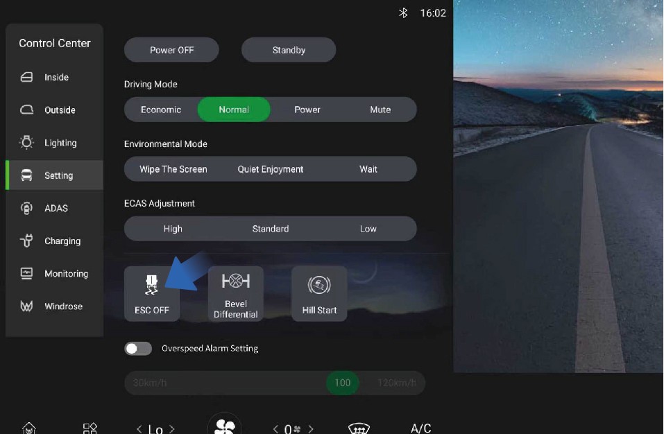 Operating instructions
Function introduction
Driving Assistance
The electronic stability control (ESC) is a system integrating numbers of comprehensive strategies for stability control of the vehicle. It is intended to improve the handling performance of the vehicle and prevent the vehicle from losing control when it reaches its dynamic limits. The ESC improves the safety and controllability of the vehicle.
The ESC mainly has two sub-functions:
Direction control: When the vehicle is oversteered or understeered, the ESC brakes a single wheel to correct the
↑ TopYou can manually turn off the ESC by selecting "Control Center", switching to "Setting" interface, and clicking "ESC OFF" button on the vehicle information screen of the instrument panel.
After the ESC is turned off, the corresponding ESC OFF indicator will be displayed on the instrument cluster.
Precautions
NoticeWhen the ESC is faulty, the yellow ESC MIL on the instrument cluster will be illuminated. You should contact a Windrose authorized service center as soon as possible to have the system repaired.
Note
ESC is turned on by default when the vehicle is started. When the vehicle restarts, ESC will also be turned on automatically.
The ESC OFF switch controls activation and deactivation of both ESC and ASR. When ESC is turned off, the ASR will also be turned off.
Blind spot information system (BSIS)
↑ TopDriving Assistance
The BSIS system detects pedestrians and cyclists in the vehicle's blind spots. When the vehicle is stationary and detects an object entering the danger zone, the BSIS alarm screen immediately triggers an alert, with the dashboard indicator lights activating simultaneously. If the corresponding indicator is on and the vehicle is moving forward, the dashboard will sound and flash the alarm until the pedestrian completely exits the danger zone.
BSIS warning
Level 1 warning
When the vehicle's BSIS sensor detects the presence of a bicycle rider with a speed of 3–12 mph entering its detection area, the BSIS system displays a yellow warning light on the instrument panel and BSIS alarm screen through optical signals, alerting the driver until the target leaves the alarm area.
Level 2 warning
On the basis of the first level alarm, when the vehicle is in forward gear and the indicator on the side with the target object is synchronously activated, the BSIS system displays a red warning light on the instrument panel and BSIS alarm screen through optical signals, synchronously emitting an alarm sound to inform the driver that the target has left the alarm area.
BSIS fault warning
When the system fails, a pop-up window will appear once, and the function switch in the setting interface of the IHU control screen will be turned off and grayed out, prompting the operator that the function is unavailable.
Operating instructions
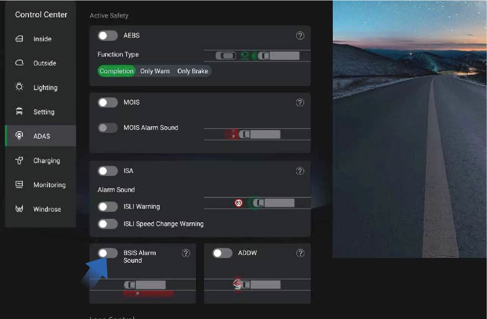
You can switch to the control center by selecting "Control Center" from the car's infotainment screen on the right side of the dashboard. On the "ADAS" interface, click the "BSIS Alarm Sound" button to turn on/off the BSIS function alarm sound.
Limitations of BSIS
In any of the following situations, BSIS may not be able to detect targets or work well. We recommend that you do not rely too much on BSIS:
Adverse weather conditions such as snow and fog, as well as low light environments, prevent the system from detecting targets.
Changing lanes directly without turning on the turn signal.
The target is relatively small or moves slowly and is in a stationary state.
The vehicle is making a sharp turn or in an open area.
When there is a system malfunction (such as camera, controller, alarm, brake, steering, etc.).
Precautions
Warning
BSIS is a driving assistance function, and it cannot replace your observation and judgment of traffic conditions and the driver's responsibility for safe driving.
ADDW
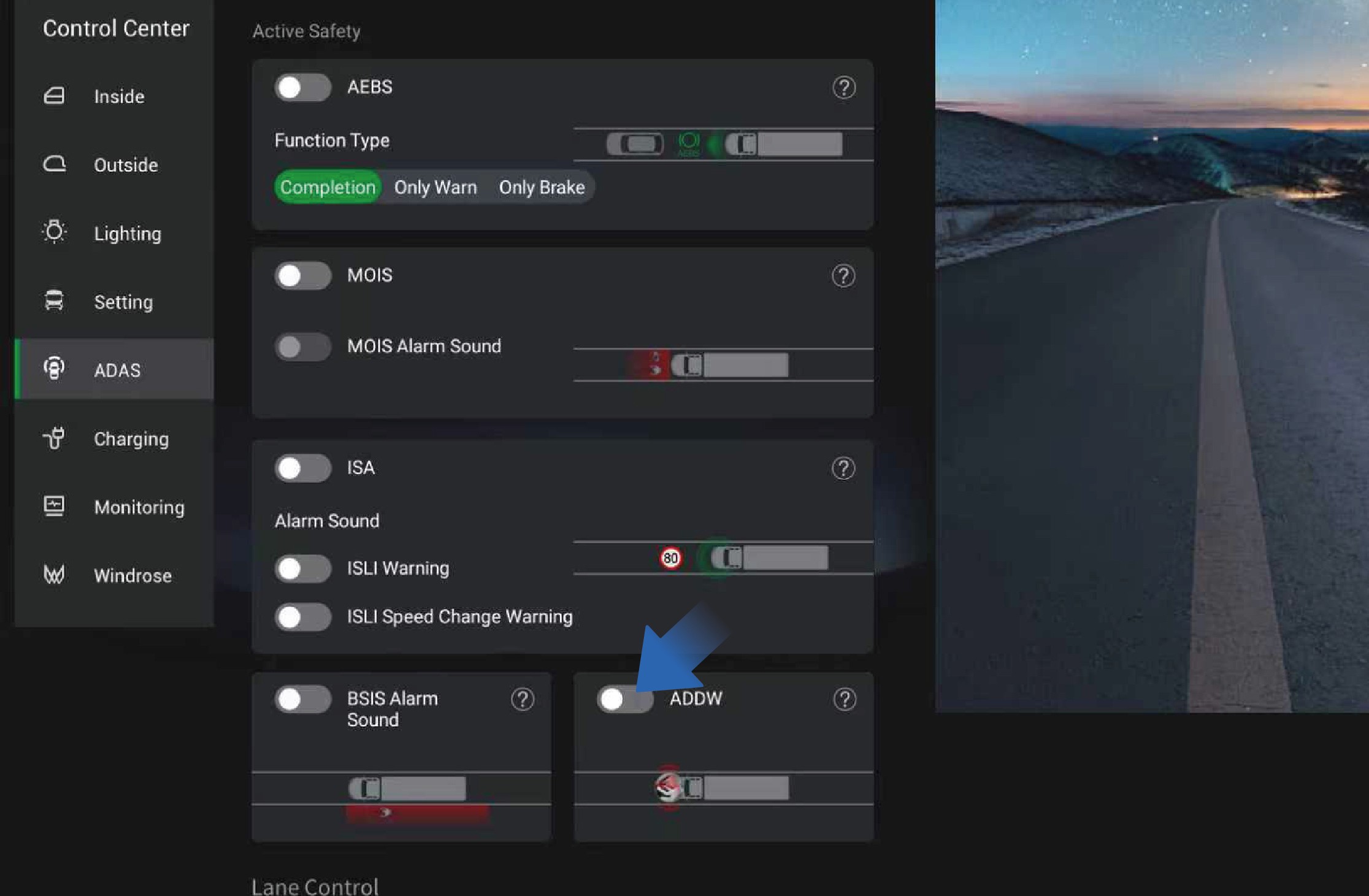
Driving Assistance
Do not rely too much on the BSIS, and it is forbidden to test the triggering of the function intentionally or wait for the function to be triggered intentionally. Due to the inherent limitations of system performance, false triggering and missed triggering cannot be completely avoided.
ADDW is the Driver Distraction Warning System, which issues a
warning when the driver is distracted; When the ADDW switch is turned off, the distraction reminder function can be turned off during the current power-on period
Intelligent Speed Assistance (ISA)
↑ TopFunction introduction
Driving Assistance
The ISA system combines forward facing camera recognition and offline maps to detect speed limits. When the system detects the perceived speed limit, the dashboard will display the perceived speed limit of the current road. If the vehicle speed exceeds the perceived speed displayed on the dashboard, the system will emit a flashing light signal and an audible signal warning. Releasing the accelerator or stepping on the brake can terminate the audible warning.
The ISA function can be completely turned off until it is turned on again or the vehicle is restarted.
You can switch to the control center by selecting "Control Center" from the car's infotainment screen on the right side of the dashboard. On the "ADAS" interface, click the "ISA" button to turn on/off the ISA function.
Drivers can turn on or off the overspeed warning sound through the settings option; Drivers can set the recognition speed limit change reminder sound to be turned on or off through the settings.
Identification and detection of vehicle speed limit sign by ISA
The ISA perception system can detect and recognize speed limit signs within 164.0 ft ahead.
The ISA perception system can detect speed limit signs within a height of no more than 23.0 ft.
The ISA system can recognize speed limit signs that comply with national standards.
The ISA system can detect multiple speed limit signs within a visible range.
The ISA system is capable of detecting and identifying embedded speed limit signs.
ISA function failure
When the system detects a sensor malfunction that the system function depends on, excluding sensor obstruction, the driver should be informed of the system malfunction status through a fault signal.
When the system detects a malfunction in the associated electronic components, it should inform the driver of the system's fault status through a fault signal.
As long as there is a malfunction, it should continue to be displayed after the vehicle is powered on.
Precautions
Warning
The speed limit information and speed measurement information are for reference only. Please refer to the information on the actual road and drive the vehicle safely.
Affected by driving environment, the camera may send false alarms when it detects a sign similar to the speed limit sign. For this reason, the driver should not rely solely on the system for judgment at any time.
Hill Start Assist (HSA)
↑ TopDriving Assistance
The hill start assist (HSA) helps you prevent the vehicle from moving backward when starting on a slope. The HSA will keep the vehicle stationary on a slope for a short time after the brake pedal is released.
Operating instructions
↑ TopYou can activate/deactivate the function by selecting "Control Center", switching to "Setting" interface, and clicking "Hill Start"
button on the vehicle information screen of the instrument panel. When the vehicle is going to start on the ramp, first depress the brake pedal, release the parking brake, and then press the HSA button in the IHU control screen to activate the HSA function. At this time, the HSA indicator on the instrument cluster will be illuminated, and the driver should start the vehicle within 3S. Before the HSA is deactivated, the HSA indicator on the instrument cluster
Precautions
Warning
The HSA is not a substitute for EPB. When you are going to leave the vehicle, be sure to depress the brake pedal and enable the EPB.
If the vehicle starts to slip backward, the brake pedal should be depressed immediately. The HSA cannot prevent the vehicle from rolling backwards on a steep slope under full load or on special roads.
It is forbidden to depress the brake pedal and the accelerator pedal simultaneously when starting on a slope.
Note
It is recommended to turn off the HSA immediately after the vehicle starts; If continuous start is required, turn off the HSA after continuous hill start is completed.
It is recommended to turn off the HSA when driving on level roads.
The HSA is turned off by default when the vehicle is started.
↑ Topwill flash rapidly.
Steering Wheel Tire Emergency Safety Device (TESD)
Driving Assistance
When replacing tires, the operator needs to remove the tire emergency safety device first, next remove the tire, install the new tire, and then refit the tire emergency safety device.
Function introduction
↑ TopThe tire emergency safety device is a passive safety device that can effectively prevent the wheel hub from contacting the ground at the moment of a tire blowout, so that the steering force and braking force of the vehicle can still be controlled to ensure the safety of personnel and vehicles at the first time.
Precautions
Note
When the removed tire emergency safety device is refitted, it is necessary to check whether the device is damaged. Only when it is confirmed that there is no damage can the device be used again, but the bolts and nuts must be replaced with new ones. If damaged, a new tire emergency safety device needs to be installed.
Electro-Hydraulic Power Steering (EHPS)
↑ TopDriving Assistance
Function introduction
The electro-hydraulic power steering (EHPS) realizes steering assistance and intelligent driving assistance by controlling the hydraulic power output of power motor.
For steering, the system will provide steering assistance to enhance the controllability and stability of the vehicle and make steering easier.
Active steering alignment
After steering, the EHPS will calculate the angle and speed of active steering alignment according to the steering angle and the vehicle speed at that time, to realize the active alignment of steering wheel.
Speed-dependent power assist
When the vehicle turns at high speed, the opposite direction force is appropriately increased linearly; When the vehicle turns at low speed, the same direction force is appropriately increased linearly to adjust your steering feel and provide speed-dependent assistance.
Hands-off detection (HOD)
↑ TopThe EHPS system can determine whether you have taken your hands off the steering wheel based on the steering wheel torque.
Precautions
Warning
When the EHPS system fails, contact a Windrose authorized service center in time to check and repair the system.
EHPS is only a driver assistance function and cannot replace your steering wheel control. During driving, you are always responsible for controlling the steering wheel to steer.
Electronic-Controlled Air Suspension (ECAS)
↑ TopDriving Assistance
Function introduction
The electronically controlled air suspension (ECAS) drives the solenoid valve in the control mechanism by collecting the height of the frame and the axle, airbag pressure, vehicle speed signal, braking signal and operation switch signal, to realize the inflation and deflation of the airbag, thereby achieving the raising and lowering of the suspension.
Instructions for operation of remote control The remote control is indispensable to ECAS on the truck. It integrates commonly used raising and lowering buttons of ECAS
for manual raising and lowering of the front and rear axles,
restoration of normal height, and memory height control.
The remote control is fixed in the storage cabinet under the right instrument panel and it can be taken out for use.
The remote control button is a self-resetting, inching button, and when using the button, you should select the target position (front/ rear axle), then the corresponding indicator will be illuminated, and the target airbag will be lifted and lowered.
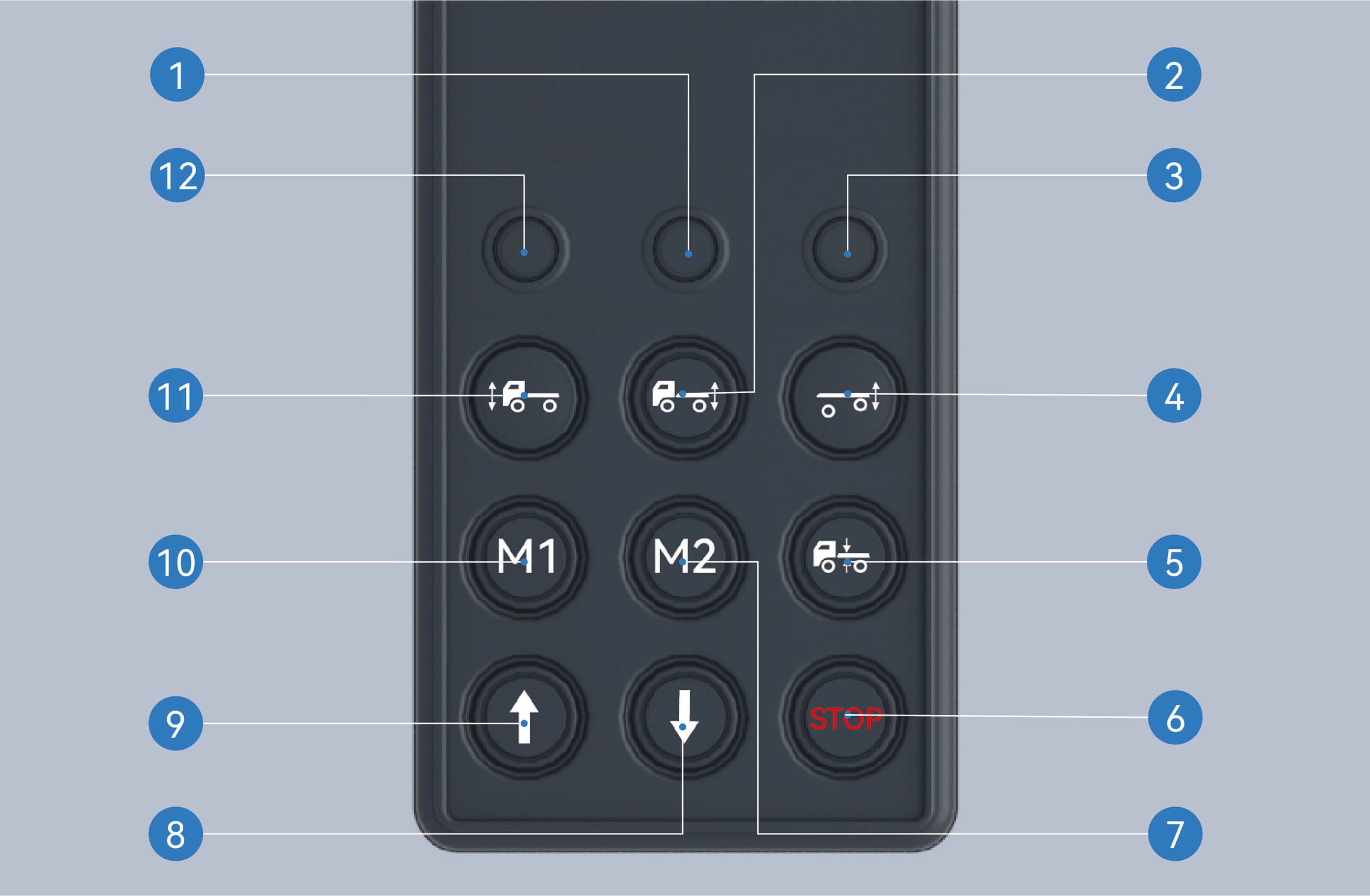
Rear axle indicator
When the rear axle is selected, the rear axle indicator will be illuminated and you can operate the rear axle.
Rear axle selection button
After pressing this button and selecting the rear axle, the rear axle indicator will be illuminated.
Lifting axle indicator
When the lifting axle is selected, the lifting axle indicator will be illuminated and you can operate the lifting axle.
Lifting axle selection button
After pressing this button and selecting the lifting axle, the lifting axle indicator will be illuminated.
Reset button
When selecting the axle, the indicator will be illuminated. When you press the button at this time, the selected axle will return to normal height.
Stop button
After pressing this button, any raising and lowering of the vehicle that is in progress will be stopped.
Memory height M2
Activation of memory height M2: After selecting the front/ rear axle, press this button to automatically adjust the current axle height to memory height M2.
Storage of memory height M2: Select the front/rear axle, adjust the axle position to the height to be memorized, press and hold the stop button without releasing it, press this button simultaneously, hold it and release after 2 seconds.
Lowering button
Press this button to lower the axle.
Raising button
Press this button to raise the axle.
Memory height M1
Activation of memory height M1: After selecting the front/ rear axle, press this button to automatically adjust the current axle height to memory height M1.
Storage of memory height M1: Select the front/rear axle, adjust the axle position to the height to be memorized, press and hold the stop button without releasing it, press this button simultaneously, hold it and release after 2 seconds.
Front axle selection button
After pressing this button and selecting the front axle, the front axle indicator will be illuminated.
Front axle indicator
When the front axle is selected, the front axle indicator will be illuminated and you can operate the front axle.
Instructions for operation of vehicle information screen
You can select the appropriate driving height by selecting "Control Center", switching to "Setting" interface, and clicking "ECAS Adjustment" button on the vehicle information screen of the instrument panel.
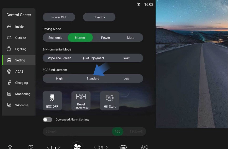
High
When driving on bumpy roads or wading roads, you can select a larger driving height to prevent the wheel from jumping and contacting the frame, etc.
The height of the high-level airbag is increased by 1.97 in relative to the standard height.
Standard
The standard height controlled by the vehicle information screen and the standard height controlled by the remote control are the same.
If the airbag is not in the standard position, the non-normal height warning icon will be illuminated on the instrument cluster.
Low
At high speeds, a smaller driving height can be selected to improve the ride comfort of the vehicle and reduce energy consumption to a certain extent.
The height of the low-level airbag is reduced by 1.38 in compared to the standard height.
Precautions
WarningWhen the ECAS is faulty, the red ECAS MIL on the instrument cluster will be illuminated. You should contact a Windrose
authorized service center as soon as possible for inspection and repair of the system.
Notice
The airbag cannot be raised or lowered when the pressure in the air reservoir is insufficient.
When the vehicle speed exceeds 6 mph, the manual button control function of ECAS will be disabled.
When the vehicle is just powered on, if the airbag is not in the normal position, ECAS will automatically return to and maintain at the standard height immediately.
If the airbag is not in the normal position, when the vehicle accelerates from standstill state to above 6 mph, it will automatically return to the standard height and maintain at the normal height.
The front/rear airbag can be raised by up to 3.35 in and lowered by up to 1.97 in.
If the airbag is not at the standard position, the non-normal height warning icon will be illuminated on the instrument cluster.
Note
- The vehicle can be driven for a long time at the height you have selected on the vehicle information screen.
Tire Pressure Monitoring System (TPMS)
Driving Assistance
↑ TopFunction introduction
↑ TopThis vehicle is equipped with a tire pressure monitoring system (TPMS), which allows you to check the tire pressure status of the vehicle at any time.
Operating instructions
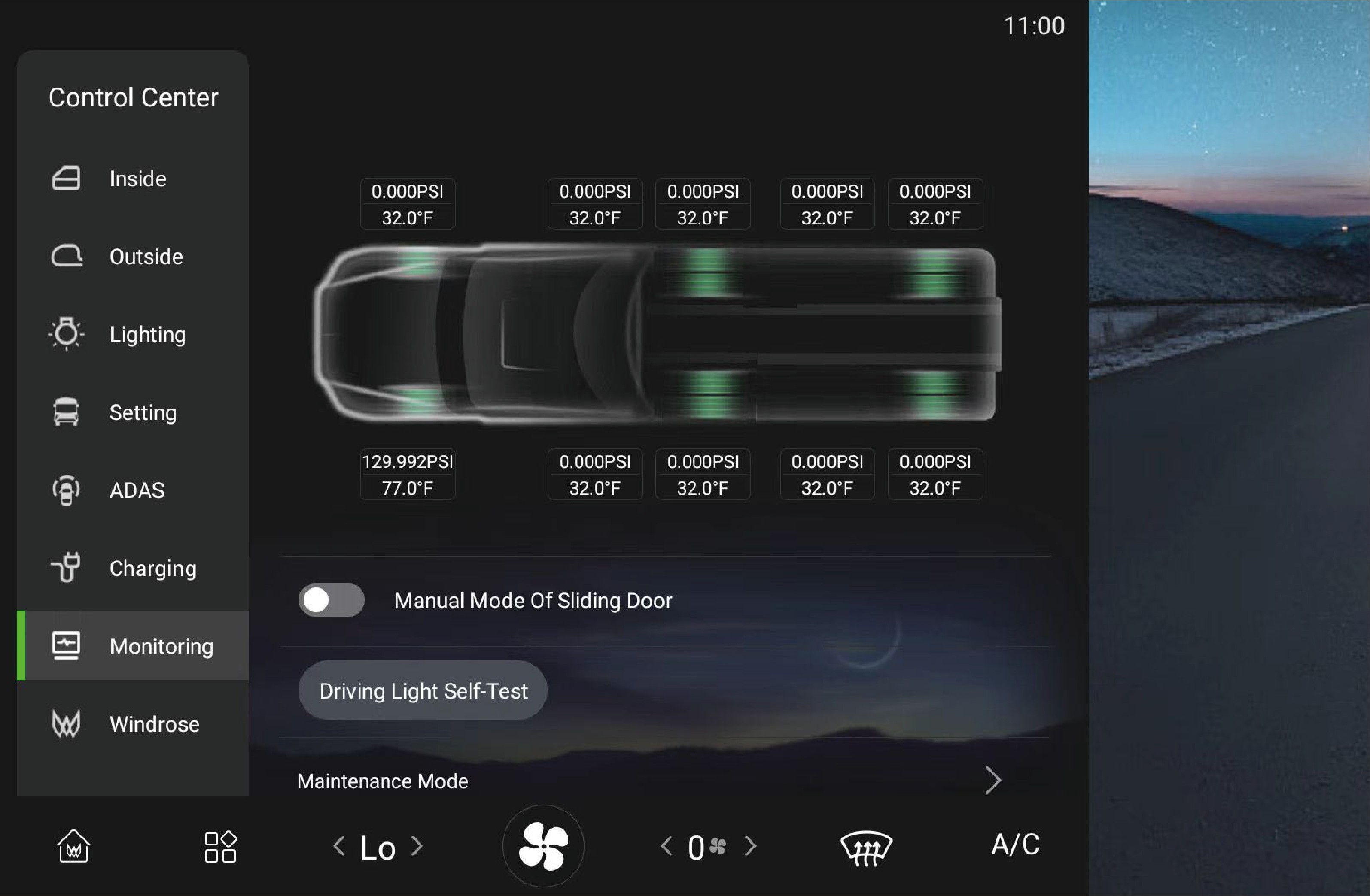
↑ TopYou can check the current tire pressure and temperature monitored by TPMS by selecting "Control Center" and switching to "Monitoring" interface on the vehicle information screen of the instrument panel. If the current tire pressure and temperature cannot be displayed, contact a Windrose authorized service center.
If the pressure or temperature of one or more tires is abnormal, the sensor is lost, or the tire is leaking rapidly, the tire pressure warning lamp will be illuminated on the instrument cluster, and a pop-up window will appear to describe the cause of the fault and the location of the faulty tire, accompanied by a period of "beeping" sound to prompt you to stop as soon as possible, check the tires, and contact a Windrose authorized service center for checking and repair of the system.
Precautions
↑ TopNoteThe TPMS is based on tire temperature and atmospheric temperature. In the areas with high altitude or low temperature, it may be necessary to inflate the tires to a slightly higher pressure to clear the low tire pressure alarm.
Multimedia Overview
Multimedia System
You can click here to turn off the in-vehicle infotainment screen.
Application Center
You can click here to view or use related applications.
Radio
You can click here to switch to the radio interface and listen to local radio stations.
Local music
You can view or play music files stored in the IHU system here.
Home page
You can click here to return to the home page.
Music player
You can pause and switch music here.
Mobile phone interconnection
You can click here to connect your phone to the IHU.
Bluetooth phone
After the on-board Bluetooth is connected to the phone, you can use it to answer/make calls in the vehicle.
In-vehicle infotainment screen switch
Function introduction
Multimedia System
cleaning, just press and hold the vehicle information screen for a while to illuminate the screen.
Quiet enjoyment: After clicking "Quiet Enjoyment", you can
↑ TopThe vehicle information screen is equipped with three environment
modes to choose from, depending on your usage.
Operating instructions
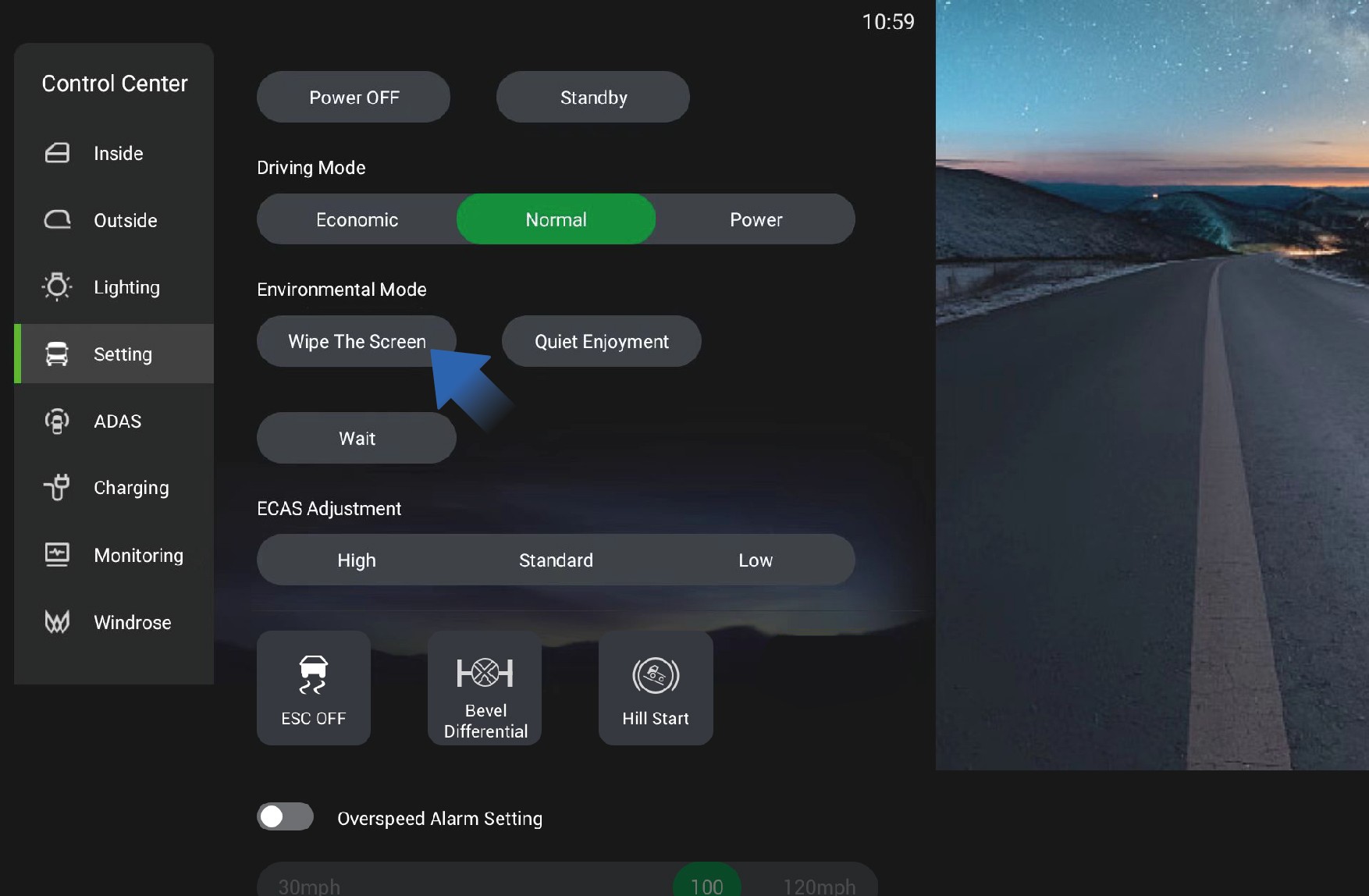
You can click "Setting" in the system settings interface on the vehicle information screen to select the environment mode:
Screen cleaning: After clicking "Wipe The Screen", the vehicle information screen will immediately go black to facilitate the
choose and play the desired ambient sound, and the vehicle information screen will immediately go black. When you need to illuminate the screen, just double-click the vehicle information screen.
Wait: After clicking "Wait", the vehicle information screen will immediately go black. When you need to illuminate the screen, just double-click the vehicle information screen.
Driver's Tools
Emergency Handling
weather, the sign must be positioned 656.2 ft away from the vehicle.
This vehicle is equipped with driver's tools when it leaves the factory. The driver's tools are stored in the tool box on the left side of the vehicle for emergency use in specific situations, including:
Towing hook
Warning triangle
Safety Hammer
↑ Top
Emergency Handling
Towing hook
When towing this vehicle, you need to install the towing hook in place first and ensure the stability of the vehicle on the towing vehicle.
Triangular Warning Sign
When an emergency renders the vehicle immobile, turn on the hazard warning lights first, then place the triangular warning sign at a sufficient distance from the rear of the vehicle. The required placement distance of the sign varies depending on the environment and road type. On regular roads, it should be placed 164.0 to 328.1 feet away from the vehicle; on expressways, the distance should be 492.1 feet; and in rainy, foggy or snowy
In the event of an emergency or disaster, the doors may not be
able to open, including but not limited to the following situations:
Vehicle fire
When a vehicle catches fire, the fire may cause the doors to deform and fail to open.
Vehicle falling into water
When a vehicle accidentally falls into water, the doors will be difficult to open due to the pressure difference between the inside and outside.
Traffic accident
↑ TopIn a major traffic accident, the collision may cause the doors to deform and fail to open.
In this case, you can use the safety hammer equipped with this
vehicle to break the window and escape.
Operating instructions
1. Take out the safety hammer
The safety hammer is located on the right side of the electric sliding door and can be directly removed for use.
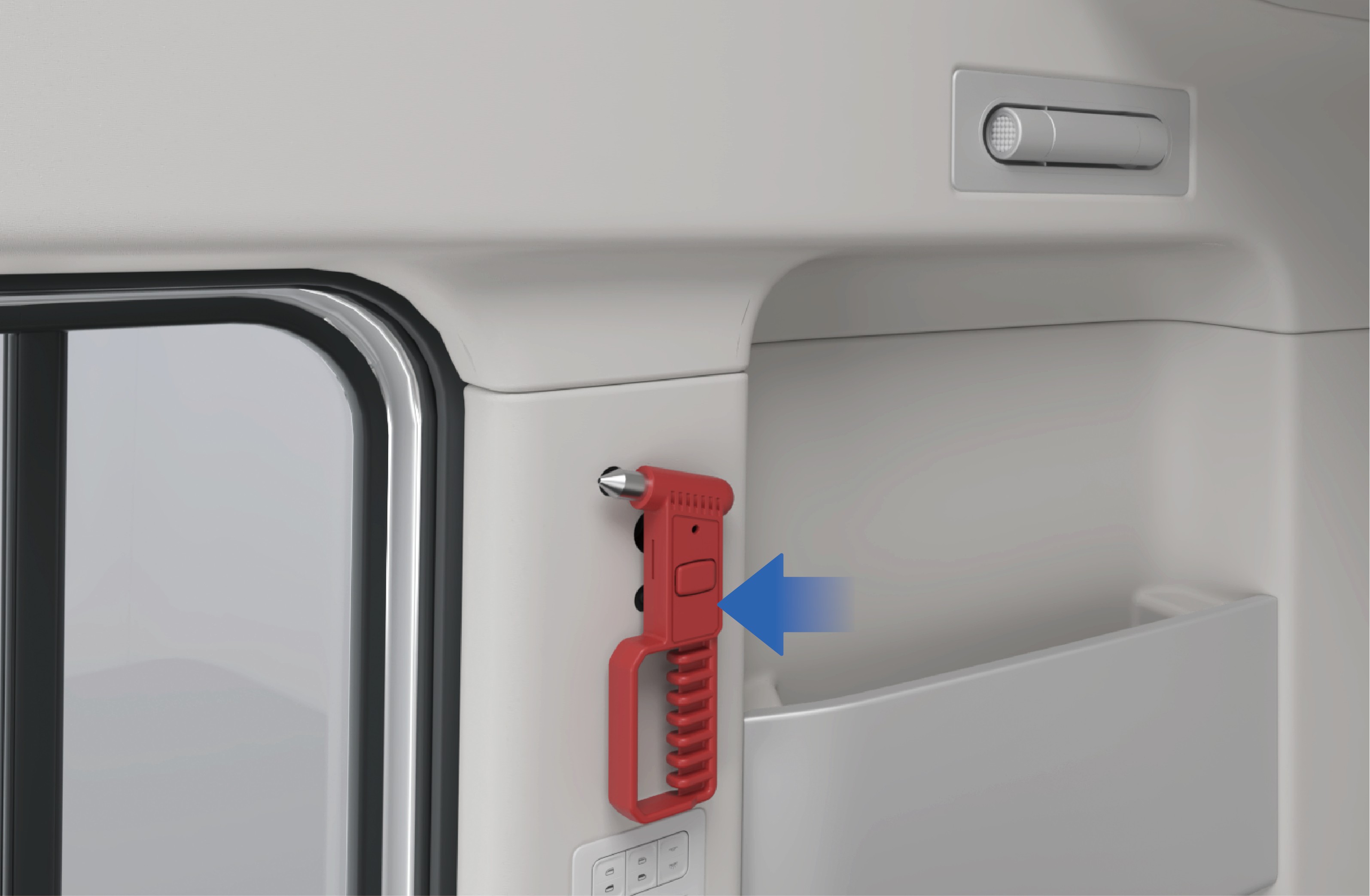
Break the window
Aim the sharp end of the safety hammer at the four corners or edges of the window, and strike hard until the window is broken.
Escape from the vehicle
↑ TopEscape from the inside of the vehicle and stay away from the vehicle in a safe place. Call the police and wait for rescue.
Precautions
Warning
The corners and edges of tempered glass are relatively weak, making it easier to break for evacuation.
Glass may not immediately come off after being shattered due to film or other reasons. In this case, the glass can be forcefully impacted to come off.
Regularly check the safety hammer to ensure that it is in good working condition.
Fire Extinguisher
↑ TopEmergency Handling
Towing a Trailer
Vehicle Recovery and Towing
↑ TopEmergency Handling
When the vehicle cannot be driven due to breakdown or accident, contact a Windrose authorized service center immediately for professional recovery and towing service. Do not attempt to tow the vehicle without following proper procedures. Incorrect towing may cause serious vehicle damage, loss of braking, or a road traffic incident.
NoticeBefore towing, verify that the vehicle has adequate brake air pressure. If brake pressure is insufficient, the rear axle spring brake actuators must be released mechanically or pneumatically to prevent the brakes from locking.
The fire extinguisher is placed at the lower left of the sleeper, which can be used to suppress a fire in an emergency.
WarningIn an emergency, please extinguish the fire and contact the fire department for disposal only if it is safe to do so.
Towing
When your vehicle needs to be towed out of trouble, follow the steps below:
Take out the towing hook from the tool box on the left side of the vehicle.
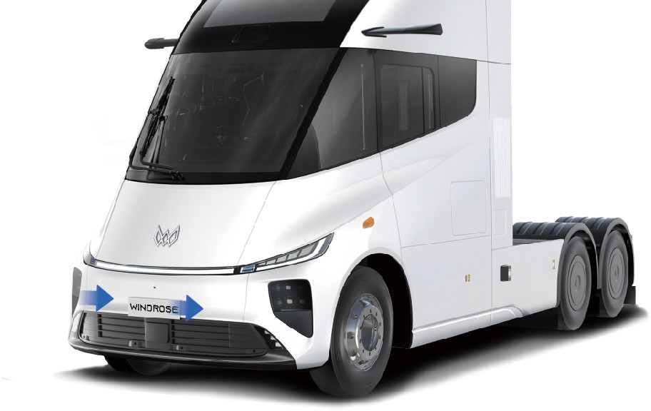
Open the cover plate of the towing hook mounting holes, which are located on the front left and right sides of the vehicle.
Screw the towing hook into left or right towing hook mounting hole according to the actual conditions, and make sure that the hook is completely screwed in without shaking. If there are impurities or oil stains in the towing hook thread, please clean it before screwing in the towing hook. Before installing the towing hook, make sure that the vehicle is stationary.
Connect the towing device on the towing vehicle to the towing
hook.
Keep the vehicle powered on to ensure that the steering and braking systems can operate normally.
Turn on the hazard warning lamps.
Start the towing vehicle to help the faulty vehicle get out of trouble.
WarningThe original towing hook is made of special materials and has high strength. If you use a towing hook that is not factory-fitted, the towing hook may be broken. If you need to buy a new towing hook, contact a Windrose authorized service center.
Notice
If this vehicle is connected to a trailer, disconnect the trailer before towing.
If this vehicle is stuck in mud or soft dirt, do not suddenly tow the vehicle outward. Also avoid oblique or lateral traction to prevent the vehicle chassis form damage.
When starting the towing vehicle, pay attention to controlling the vehicle speed and avoiding towing the faulty vehicle too fast or too hard to prevent vehicle form damage and endangering other road users.
When towing this vehicle, the towing vehicle speed must not exceed 9 mph to avoid damage to the vehicle drive motor.
When arriving at the destination, be sure to slow down and stop towing the vehicle. After completing the towing operations, please clean up the site in time, remove the towing hook and put it back in place, and close the towing hook protective cover.
The towing hook can be used to get the vehicle out of trouble, and do not tow the vehicle for long distances.
Towing is allowed only when there is no safety risk to the vehicle. In case the battery pack is deformed, leaks, smokes, etc., you should eliminate safety risks immediately.
Brake Failure
Emergency Handling
↑ TopEmergency operation
If the brake fails suddenly while driving, please turn on the hazard warning lamps immediately, hold the steering wheel firmly, and pay attention to avoid and alert passing vehicles by visual and acoustic alarms.
Slowly turn on the electronic parking brake, observe the driving conditions and use ramps or the runaway truck lane to assist parking if necessary.
For special road conditions such as winding mountain roads, bridges, cliffs, etc., you should also hold the steering wheel firmly to avoid getting into a dangerous situation such as falling off.
Follow-up procedures
↑ TopAfter parking the vehicle, place warning signs around the vehicle and block the wheels with wedges to prevent the vehicle from slipping, and contact a Windrose authorized service center for inspection and repair of the vehicle.
Prevention measures
Regularly maintain the brake system.
Check the free travel of brake pedal regularly.
↑ TopNoteIt is strictly forbidden to immediately apply emergency brakes when the brakes fail, otherwise it may cause the vehicle slipping and even roll-over.
Out-of-Control Steering or Steering Failure
↑ TopEmergency Handling
Emergency operation
When you lose control of steering wheel suddenly while driving on common roads (straight driving), release the accelerator pedal first, turn on the hazard warning lamps as soon as possible, and depress the brake pedal evenly.
Before driving, check whether the steering wheel rotation meets the standard requirements.
Before driving, check whether the steering pitman arm, ball joint, tie rod, etc. are loose.
When braking, try to avoid wheel locking.
NoticeDo not perform emergency braking immediately when you lose control of steering wheel suddenly on common roads, otherwise it will cause the vehicle slipping and even roll-over.
When you lose control of steering wheel suddenly while driving
↑ Topon special roads (curves, mountain roads), release the accelerator pedal should be released immediately, apply the
brakes quickly to stop the vehicle in time to prevent the vehicle from running off the road or colliding with other vehicles.
Follow-up procedures
Tire Burst
↑ Top
Emergency operation
Emergency Handling
After parking the vehicle, place the warning signs around the
vehicle and block the wheels with wedges to prevent the vehicle from slipping, and call the Windrose service hotline.
Prevention measures
Regularly maintain the steering system.
In the case of tire blowout, follow the steps below:
Hold the steering wheel firmly with both hands, control the driving direction, and turn on the hazard warning lamps.
Release the accelerator pedal completely, repeatedly and
lightly depress the brake pedal, and try to control the vehicle to drive in a straight line.
After slowing down, make sure that there are no vehicles or pedestrians behind and on the right side of the vehicle, and slowly pull over to the side of the road.
Vehicle Sideslip
↑ Top
Emergency operation
Emergency Handling
Follow-up procedures
After parking the vehicle, place the warning signs around the vehicle and block the wheels with wedges to prevent the vehicle from slipping.
After the vehicle stops completely, contact a towing truck for rescue.
Prevention measures
Before driving, check the tire tread and tire pressure for bulges, cracks, cuts, nails, and abnormal tread wear.
Notice
In the case of tire blowout, do not turn the steering wheel sharply, otherwise, vehicle drifting will occur.
Besides, it is forbidden to perform emergency braking operations or brake hardly (especially on highways) to avoid roll-over.
In the case of vehicle slipping, the driver should:
Release the accelerator pedal, and turn the steering wheel slightly to the side of the slipping, and turn the steering wheel back in time.
Hold the steering wheel to prevent it from turning.
Prevention measures
Before driving, check whether the tire pattern, pressure and other items meet the safety standards.
After the vehicle is started, check the braking effect of the vehicle at low speed. If there is any brake deviation, stop the vehicle immediately, check the braking system and troubleshoot the fault before driving.
Overloading and overweight will reduce the anti-rollover capacity and driving stability. Therefore, please load the vehicle properly.
When driving on slippery or icy roads, it is recommended to use the snow chains, drive at low speed, depress the brake
pedal carefully for braking, and avoid emergency braking.
When going down a long steep hill, the center of gravity shifts forward, making the vehicle more prone to tipping, so please slow down the speed, hold the steering wheel firmly,
and apply the brakes intermittently to control the vehicle speed with the help of the motor drag force.
Do not use the brakes while steering, accelerating or decelerating to ensure the optimal coordination of braking.
Before turning, be sure to slow down the vehicle in advance and turn the steering wheel properly.
It is forbidden to coast in neutral, especially when going downhill, to avoid sudden braking of the vehicle due to excessive inertia forces.
Warning
When the vehicle is slipping on wet or icy roads, do not brake and steer at the same time to avoid aggravating the slipping hazard.
If slipping is caused by braking (vehicle drifting), release the brake immediately. When it is necessary to slow down, auxiliary braking can be used.
When the vehicle slips on a curve, stabilize the vehicle first and then apply the brake intermittently.
Accidental Removal of High Voltage
↑ TopEmergency Handling
Emergency operation
When the vehicle is powered off with high voltage accidentally while driving, the driver should:
Press the hazard warning lamp switch and try to start the vehicle again.
After the motor is working, be sure to pull over the vehicle for inspection and eliminate the potential risks before driving.
If the vehicle cannot be powered on with high voltage, pull over the vehicle with the help of inertia force.
Follow-up procedures
↑ TopAfter parking the vehicle, place the warning signs around the vehicle and call the Windrose service hotline immediately.
Prevention measures
↑ TopGo to a Windrose authorized service center regularly to maintain and inspect the vehicle to ensure the stable operation of vehicle systems.
Emergency evacuation
Emergency Handling
↑ TopEmergency operation
When an emergency situation occurs and the car door cannot be opened, you can follow the following steps for emergency evacuation.
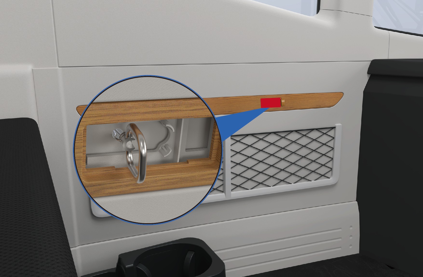 Follow-up procedures
Locate the emergency pull ring cover above the left net bag. Open the cover, and then pull the ring firmly outward to break the left window glass.
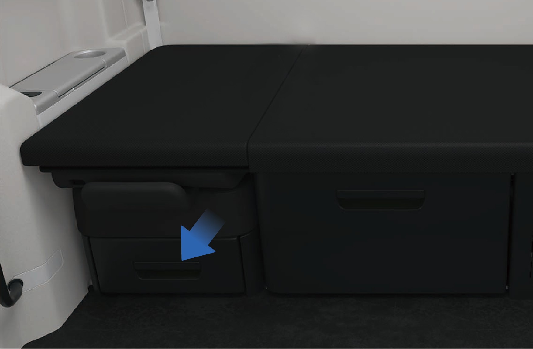
Take out the sleeper protection net from the storage box under the front passenger seat, and connect the socket at one end of the sleeper protection net to the fixed point on the left side wall.
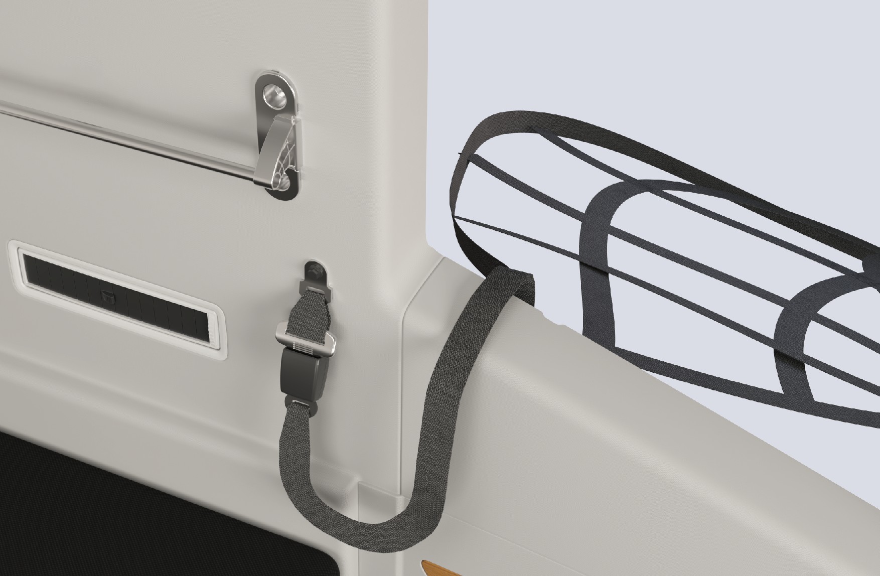
Pull the sleeper protection net out of the window, and use it as an auxiliary escape rope to quickly exit the cab.
Warning
When activating the window breaker, the broken window glass may cause glass splinters to fly. Please protect yourself by using your arm to shield your eyes.
Do not disassemble or modify the window breaker without authorization. Any product damage or other consequences resulting from unauthorized disassembly, modification, or use not in accordance with our specified requirements shall be
borne by the operator.
The window breaker can be activated underwater, but prolonged immersion in water is strictly prohibited.
Regularly check whether the fasteners of the window breaker are loose, and whether the pull ring and sleeper protective net are damaged.
During daily vehicle maintenance, prevent all components of the window breaker from coming into contact with water sources or corrosive substances, so as to avoid product corrosion and subsequent failure.
Keep away from fire sources, and replace the window breaker promptly after use.
Do not operate the pull ring arbitrarily in non-emergency situations. All consequences caused by misoperation shall be borne by the operator.
Protective Equipment for Emergency Rescue Personnel
Emergency Rescue
This vehicle is powered by a high-voltage battery system. In the event of a serious collision, hazardous conditions may occur, including high-voltage electrical leakage, battery pack damage, and chemical fluid leaks. Emergency responders must wear appropriate personal protective equipment (PPE) before approaching or working on the vehicle.
Wear impact-rated safety goggles when working on high-voltage systems.
Wear Class 0 (1,000 V rated) insulating gloves when handling any high-voltage component.
Use insulated tools rated for high-voltage work when working on high-voltage components.
Have insulating rescue hooks available.
Have a fire extinguisher rated for lithium battery fires available.
Notice
A buddy system must be used when emergency responders is working on high-voltage components. One person must supervise while another performs the work. It is forbidden for two or more people
to work simultaneously. Do not make physical contact with the person performing the work.
Emergency responders must remove all metal jewelry when performing rescue operations.
High-Voltage System Information
Emergency Rescue
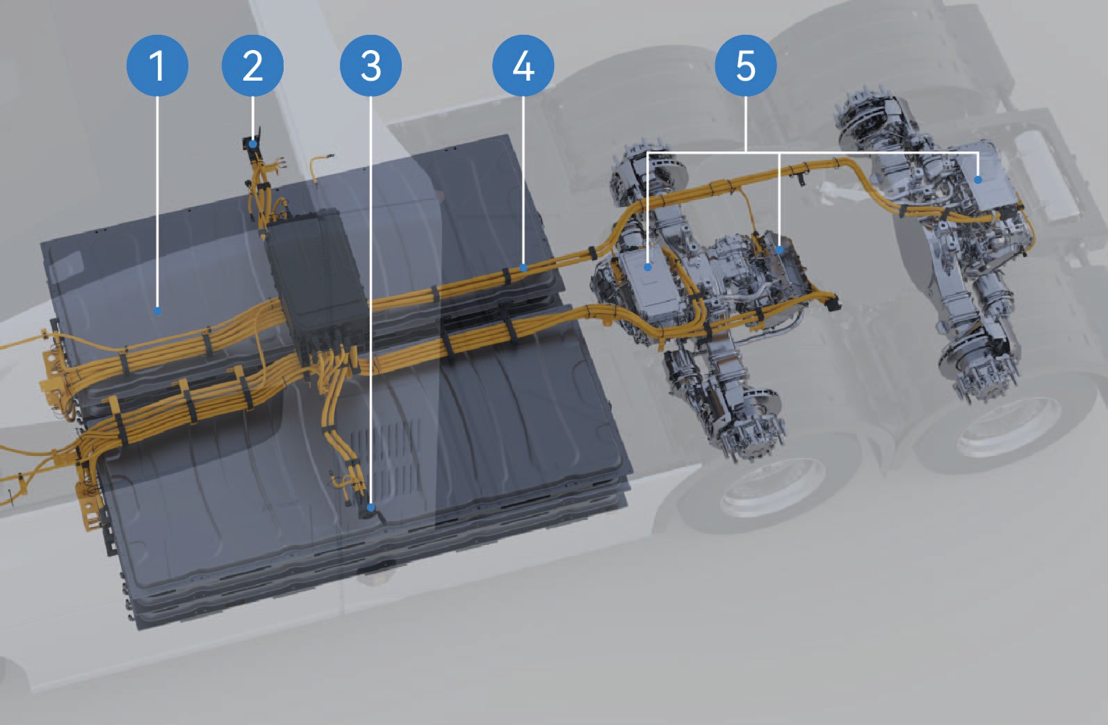
High voltage battery
Right CCS1 mode charging port
Left MCS mode charging port
High-voltage harness
Drive motor
Notice
During startup and use, do not touch parts with "high voltage warning signs" or orange parts of the vehicle.
It is strictly forbidden to trample or bump the high-voltage battery of the vehicle.
Note
When the high-voltage battery and motor MILs on the instrument cluster stay on, contact after-sales immediately and use a scan tool to read the DTC.
If the EIC system emits smoke, catches fire, or explodes, please evacuate from the vehicle immediately, call the police and take safety measures.
When working on the EIC system, please wear insulating gloves, insulating shoes, and insulate the tools. Do not make physical contact with the person performing the work.
Deactivation Method of High-Voltage System
↑ TopEmergency Rescue
High voltage cutoff from outside
Park the vehicle, apply the EPB.
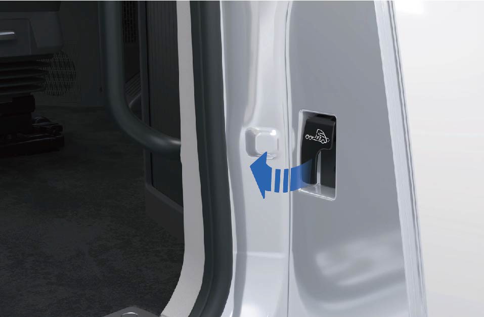
Pull the hood release handle twice in a row to release the hood.
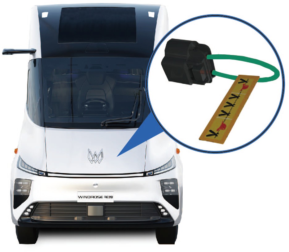
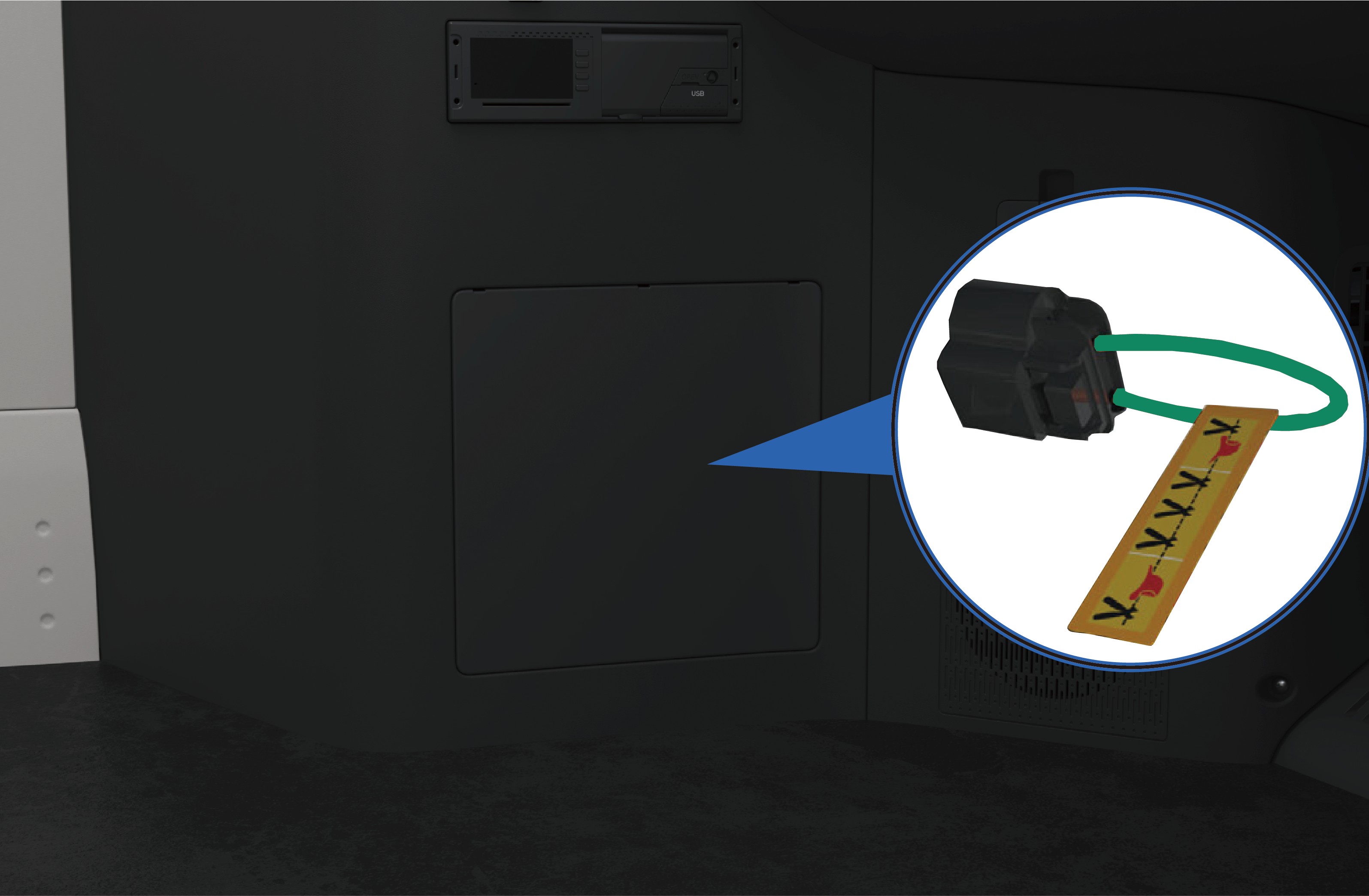
Find the low voltage MSD in the engine compartment and remove it, and the vehicle will deactivate the high-voltage system automatically.
High voltage cutoff from inside
Park the vehicle, apply the EPB.
Open the trim cover on the lower left of the instrument panel, find and disconnect the low voltage MSD, and the vehicle will automatically cut off the high-voltage system.
Warning
Be sure to wear appropriate personal protective equipment when touching any high-voltage components.
It is forbidden to touch the high-voltage battery components even though the high-voltage system has been deactivated. Be sure to wear appropriate personal protective equipment if it
is necessary to operate the high-voltage battery components.
If any damage is found in the high-voltage components, be sure to wrap the damaged parts with the insulation tapes.
Note
In an emergency, the operator can cut the orange harness on the MSD to prevent the harness from being energized again and allow the vehicle to deactivate the high-voltage system automatically.
In case of a vehicle collision, the high-voltage system will be automatically deactivate.
Rescue of Vehicle on Fire
Emergency Rescue
In the event of a vehicle fire, immediately assess the severity of the fire. If the fire is small and can be contained, emergency responders should use a suitable fire extinguisher such as a dry powder extinguisher, CO₂ extinguisher, or dry sand.
If the fire is large or the battery is found to be severely squeezed or bent, apply large volumes of water continuously to suppress the fire. Simultaneously, move all combustible materials away from the burning vehicle to prevent the fire from spreading.
Warning
If the vehicle catches fire, all occupants must evacuate immediately. Call the emergency services number according to the scene situation, and inform the emergency responders that the vehicle is a battery electric vehicle with a high-voltage battery system, which presents risks of electric shock, chemical exposure, and thermal runaway.
If the emergency responders find that there are occupants in the vehicle and the door cannot be opened during rescue, they may use a rescue tool to break the door window glass at its edge to assist trapped occupants in the vehicle break the window to escape.
↑ TopNoticeFires in high-voltage components must be extinguished using a fire extinguisher suitable for lithium batteries.
Rescue of Wading Vehicle
Emergency Rescue
A vehicle that has been driven through floodwater may show no obvious external damage, but the high-voltage system may be compromised and at risk of electrical leakage. Therefore, when rescuing wading vehicles, the emergency responders must wear appropriate protective equipment to avoid the risk of electric shock, which may cause serious injury or death.
Warning
The emergency responders must wear appropriate protective equipment before touching high-voltage system components in water to prevent electric shock.
After the emergency responders remove the vehicle from the wading area, allow the vehicle to dry completely before performing any further work, to prevent electric shock.
Necessity of Maintenance
Daily Maintenance
↑ TopRegular routine and scheduled maintenance is essential to ensure safe operation, reliability, and optimal vehicle performance, and to help minimize long-term maintenance costs.
Routine maintenance tasks described in this manual may be performed by the operator following the relevant instructions.
Windrose recommends that all scheduled maintenance be performed at a Windrose authorized service center.
NoticeThe operator is responsible for maintaining the vehicle and ensuring that all components comply with applicable US federal and state road-vehicle regulations, including the relevant federal motor vehicle safety standards (FMVSS) and roadworthiness requirements, including but not limited to tires, side deflectors, roof deflectors, side skirts, bumpers, front covers, and the vehicle speed limiter. You must ensure that the performance of these components always meets or
exceeds the original-specification components that are replaced.
of this manual.
This manual provides the information needed to operate and maintain the vehicle and its components. More detailed information of vehicle maintenance is contained in the Windrose Product Warranty Manual.
This vehicle must be regularly inspected and maintained as indicated in the Windrose Product Warranty Manual, in order to ensure coverage of the vehicle under the manufacturer's warranty The systems installed on the vehicle are sophisticated and there are strict after-sale service requirements for electric vehicles in accordance with national laws and regulations. Therefore,
NoteIf you have any questions about how to maintain your vehicle, contact a Windrose authorized service center directly for help.
Service Mode
↑ TopDaily Maintenance
Inspection of Electric Drive System
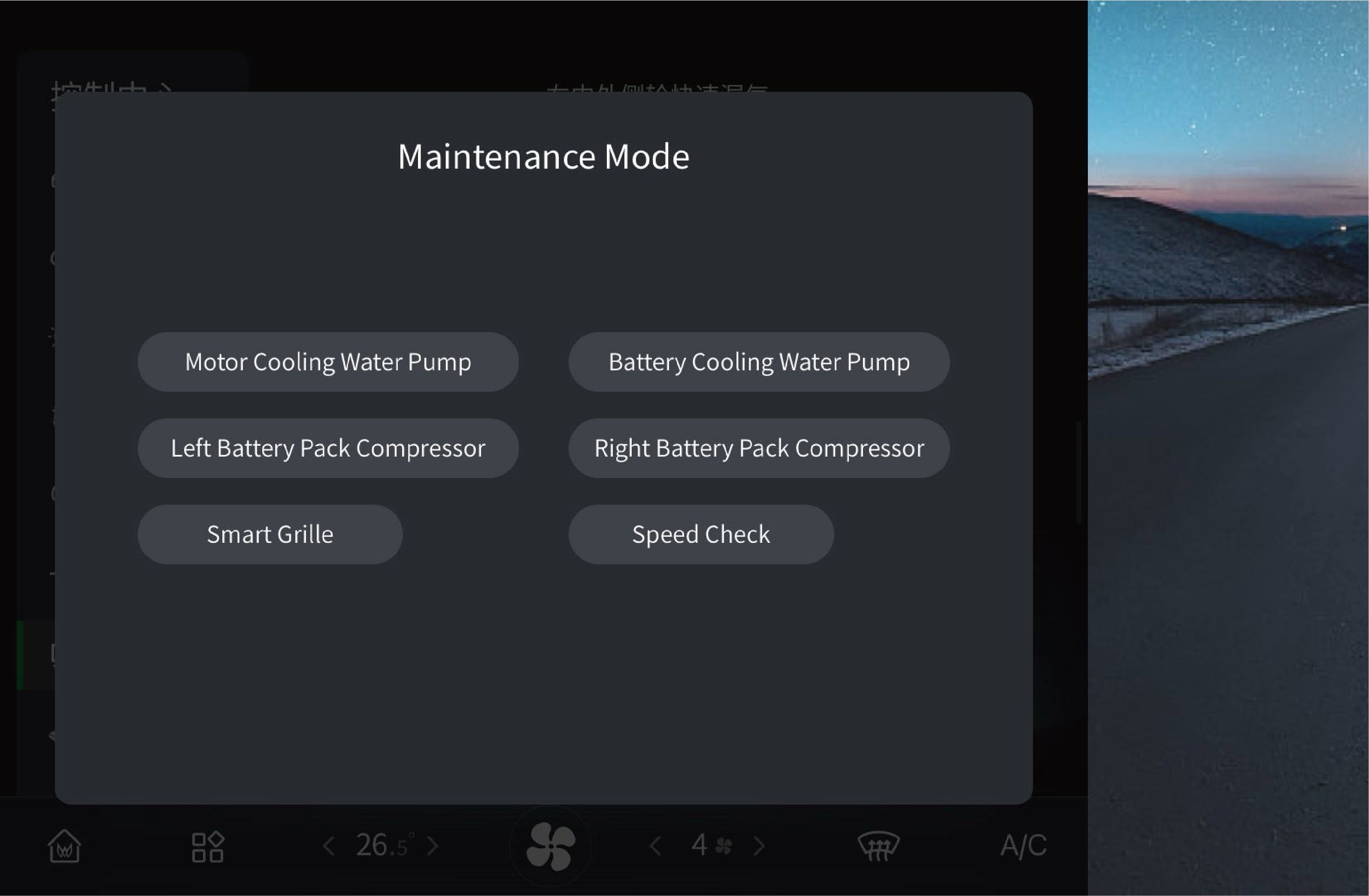 Daily Maintenance
Before starting the vehicle, check whether the relevant data displayed on the instrument cluster is normal. If the data is abnormal, do not drive the vehicle. Instead, record the system fault type and related data, and report the information to the Windrose authorized service center.
NoticeIf the high-voltage battery or motor system fails, contact a Windrose authorized service center for repair in time.
The speed limit test switch in the service mode is only used for inspection of vehicle speed limit. After activating this function, the switch will be highlighted. It must be kept closed during normal driving.
The motor coolant pump switch, battery coolant pump switch, left battery pack compressor switch, right battery pack compressor switch and active grille shutter switch in the service mode are only used for vehicle inspection and coolant filling. They must be kept
Tire Pressure Monitoring
↑ TopDaily Maintenance
This vehicle is equipped with a tire pressure monitoring system, which will display the tire pressure on the instrument cluster and the vehicle information screen. If the tire pressure is abnormal,
closed during normal driving.
please do not continue to drive the vehicle for a long time and contact a Windrose authorized service center in time.
Lighting Inspection
Daily Maintenance
↑ TopThis vehicle is equipped with a self-test function for verifying functionality of each driving lamp.
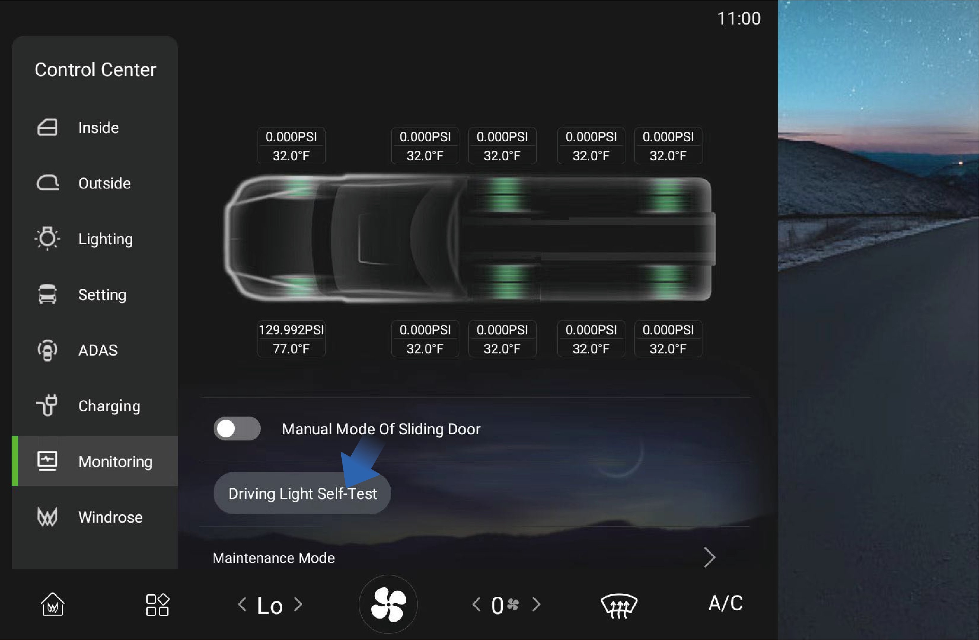 Operating instructions
↑ TopYou can activate this function by selecting "Control Center", switching to the "Monitoring" interface and clicking "Driving Light Self-Test" button on the vehicle information screen of the instrument panel. After activation, all lamps of the vehicle will be illuminated at the same time. You can observe the lamps and indicators on the instrument cluster to determine whether there is a faulty lamp.
Precautions
↑ TopWarningIf any, contact a Windrose authorized service center in time to check and repair the vehicle lamps.
Inspection of Horns and Wipers
Daily Maintenance
Check the electric/air horns as below:
Park the vehicle, press the horn button on the steering wheel to check whether the electric horn is working properly.
Press the electric/air horn change-over switch, press the horn switch repeatedly, and check whether the air horn is working properly.
Power on the vehicle, turn on the wiper switch, and check whether the wiper is working properly at each gear.
High-Voltage Battery
↑ TopRoutine Maintenance
Position of high-voltage battery
The high-voltage battery is located under the floor of the vehicle. When the vehicle is driving on bumpy or uneven roads, be careful to prevent collisions.
WarningWhen the high-voltage battery catches fire in a crash, pull over the vehicle immediately and evacuate the occupants from the vehicle and move them away from traffic. When the vehicle speed is below 12 mph, the electric sliding door will automatically unlock; When the vehicle speed is below 4 mph, the electric sliding door will automatically open. To ensure the life safety of the occupants in the vehicle, if the driver does not decelerate the vehicle within 4 minutes in the above situation, the system will decelerate and stop the vehicle automatically.
Maintenance of high-voltage battery
The high-voltage battery SOC needs to be calibrated:
once a month.
After the vehicle has been stored for more than 3 weeks, SOC calibration should be performed once at least.
Calibration method:
Use the high-voltage battery to 20% -25% SOC.
Charge the high-voltage battery fully.
Use the battery power to 40%-60% SOC.
Coolant
↑ TopRoutine Maintenance
Coolant selection
Please select the coolant with the corresponding freezing point according to driving environment to ensure the normal operation of the vehicle cooling system.
Inspection of coolant
↑ TopAfter the coolant temperature drops, check whether the coolant level in the reservoir is between the MIN to MAX marks; If the coolant is insufficient, the warning lamp on the instrument cluster will be illuminated to remind you to add coolant.
If the coolant has suspended matter, sediment or discoloration,
replace it with new coolant immediately.
Regularly check the freezing point of the coolant to ensure that it meets the requirements of the local environment and replace it regularly.
Replace the coolant
Drain the coolant as below:
Park the vehicle on the flat ground.
Turn on the EPB switch.
After the coolant temperature drops, unscrew the auxiliary water tank filler cap.
↑ Top4. Loosen the drain plug at the bottom of the radiator to drain the coolant.
Filling of coolant
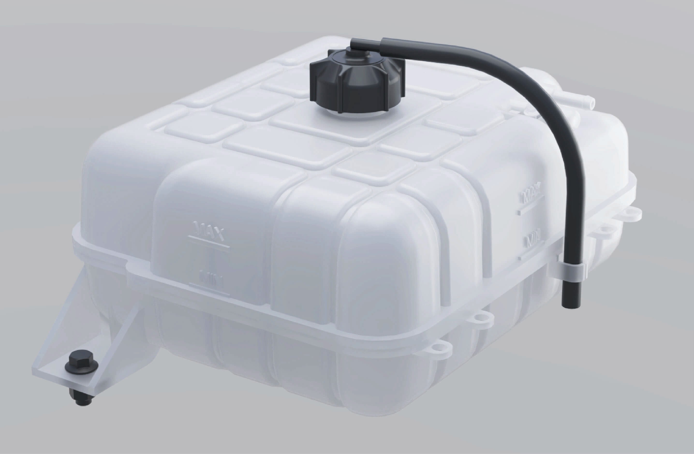
Fill the coolant as below:
Add the coolant slowly and evenly until it reaches the MAX level, and tighten the filler cap.
Power on the vehicle and run the water pump for about 10 minutes.
Power off the vehicle and add coolant to the MAX level.
Tighten the auxiliary water tank filler cap.
Warning
Use the coolant recommended by Windrose. Do not mix different types of coolant to avoid reactions that may corrode the motor and radiator or block the cooling system.
Never add liquids other than coolant to the cooling system to avoid damaging the motor and other components.
Do not step on the auxiliary water tank.
Notice
Check, add and replace the coolant regularly.
Rinse the cooling system repeatedly with clean water for ≥3 times when adding or draining the motor coolant for the first time.
When adding the coolant, keep the motor and room temperature ≤113°F to avoid burns.
Add the coolant slowly and evenly until it reaches the MAX level
After the vehicle is powered off, the motor, ECU, radiator and other components are still hot. In this case, do not open the auxiliary water tank filler cap. Otherwise, hot coolant or steam
will spray out, causing burn injuries. Perform the inspection,
replacement and filling of the coolant after the temperature of the motor system drops.
Only professionals can remove the pressure cap on the side of the auxiliary water tank.
Cleaning of radiator
↑ TopAfter the radiator has been used for a period of time, insects, catkins, dirt or other residues in the radiator fins will reduce the cooling capacity of the cooling system. You need to check the outer surface of the radiator frequently and clean the foreign objects in time (do not flush it with high-pressure gas or water).
Maintenance of cooling system
Check the cooling system to ensure that the cooling system does not leak. Check whether the cooling system leaks before driving. There are 4 common reasons for water leakage:
The radiator welding part leaks, and the radiator should be replaced.
The aging and cracking of the hose and the rust of welding part of the pipe will cause coolant leakage. Please replace the pipe.
Using inferior coolant will cause electrolytic corrosion and leakage of the cooling system. Use a special cleaning agent to clean the cooling system, and add new coolant that meets the requirements after installation.
The cooling pipe clamp is loose. Use the corresponding tool to replace or tighten the clamp.
Tire
Routine Maintenance
Tires are the connection to the road and affect driving safety. Check the following items of the tires regularly or before driving:
Tire pressure
When checking tire pressure, note that the pressure will change with temperature.
Tread pattern
The tread pattern affects the grip and control of the tire. The smaller the depth or the fewer the pattern, the worse the grip and control of the tire.
Tire conditions
Check the tire conditions before driving:
External damage;
Foreign objects in the tread pattern;
Foreign objects in the tire (dual tires);
Cracks or dents;
One-sided shoulder tire wear or irregular tread wear.
Tire service life
When the tire is used for more than 6 years, replace it with a new one.
Warning
After parking the vehicle, wait for the tire to cool down before inflation or deflation.
The tire pressure should be kept within a reasonable range. Too high or too low tire pressure will accelerate tire wear, increase power consumption, and lengthen the braking distance. In severe cases, tire blowout may occur, resulting in traffic accidents and even personal injuries.
Before driving, you must check the integrity of the tread pattern. Excessive worn tread will cause serious slipping on wet roads (rainy days, snowy days) or when driving at high speed, resulting in loss of control of the vehicle and even personal injuries.
Cracks, dents or external damage will cause the tire blowout. If any, the tire should be repaired or replaced immediately to avoid accidents.
Notice
Please follow local and national regulations for the wear standard of the tire tread pattern. When the tread wear exceeds the specified value, the tire should be replaced as soon as possible.
Avoid contact of tires with oil, grease, fuel, etc., as this may accelerate tire aging.
When parking the vehicle, avoid only part of the tire in contact with the ground or parking on road with sharp stones.
↑ TopNoteThe correct tire pressure is specified in the tire pressure table section.
Steering System
↑ TopRoutine Maintenance
Before driving, check the free travel and looseness of the steering wheel, shake the steering wheel to ensure that it is locked. During driving, check whether there is heavy steering, shaking steering or steering offset. In case of any of the situations above, please stop driving the vehicle and contact a Windrose authorised service centre immediately.
High-Voltage Safety Maintenance
↑ TopRoutine Maintenance
Principles of safe operation under high voltage
↑ TopDo not modify and install accessories on the high-voltage system and body of the vehicle without following proper procedures. Please operate according to the regulations, otherwise it may cause fire; Considering that there is a risk of electric shock in the high-voltage system of the complete vehicle, the high-voltage system should be operated by workers
who have been subject to professional training and acquired the qualification for the employment in accordance with relevant safety regulations.
Personnel requirements
Drivers should not disassemble components attached with high-voltage warning sign without following proper procedures if they have not received any training; Do not touch high-voltage components, such as orange high-voltage cables or components that come into contact with high-voltage cables, after an accident. Failure to do so may result in a risk of high-voltage electric shock. When disassembling and repairing high-voltage electrical components, the operator should unplug the low-voltage maintenance power-off plug, disconnect the low-voltage battery power supply and cut off the high-voltage circuit simultaneously.
Operators should not wear metal ornaments, such as watches and rings, and should not have metal objects in the pockets of work clothes, such as keys, metal shell pens, mobile phones, and coins.
Operators should not bring tools unrelated to work into the work site, and must use metal tools with the handheld parts being insulated.
Before connecting the high-voltage power supply, the operator should check whether there is any debris around the high-voltage electrical appliances, and notify irrelevant personnel to stay away from the above-mentioned parts, and remind loudly when closing the switch.
Maintenance requirements
↑ TopThe maintenance and repair of the vehicle can only be carried out by service stations or maintenance units with the corresponding maintenance qualifications, and by personnel who have received the corresponding training and obtained the qualifications. Otherwise, the high voltage in the high-voltage system may impose danger and even threaten your life.
Charging maintenance
↑ TopIn case the vehicle has parked for a long time, the condition of the high-voltage battery should be checked every two weeks to prevent electric leakage in the high-voltage battery. The vehicle, if parked for a long time, should be charged and maintained
regularly to prevent the high-voltage battery that has not been
used over a long time from affecting the performance of the vehicle.
Battery
Routine Maintenance
The low voltage battery is located in the engine compartment. The service life and function of the battery are affected by many factors, such as the number of starts, driving style, driving conditions, climatic conditions, etc.:
If the battery is completely discharged multiple times, its service life may be shortened. Keeping the battery charged enough helps extend its lifespan.
The starting capacity of the battery will be weakened over time. If the vehicle is parked for a long time, the battery may need to be recharged.
Warning
- Battery electrolyte is corrosive, and if it gets into the eyes or skin by accident, rinse immediately with plenty of water and seek medical care.
The maintenance and care of the battery should be handled by professionally trained personnel.
It is prohibited to touch the positive and negative terminals of the battery with both hands or a conductor simultaneously at any time.
If the low voltage battery catches fire, be sure to leave the vehicle quickly. If the smoke is inhaled accidentally, please go to an open area and seek medical attention as soon as possible.
It is forbidden to connect the battery cell to an external 12V electrical appliance.
It is forbidden to disassemble the battery without authorization to prevent acid leakage from corroding the human body, vehicle, etc.
NoticeIf you notice the following, be sure to stop using the vehicle and cut off the power immediately. Contact the Windrose authorised service centre for further guidance:
Power cords, plugs or communication lines cracked or damaged.
Signs of overheating, smokes and sparks.
Battery pack damage (e.g. cracking), battery leakage.
The dust in the battery cell will cause the battery to discharge automatically and be easily damaged.
Cleaning of battery
Keep the battery clamp and battery surface clean and dry.
Apply a small amount of acid-proof grease to the lower end of the battery clamp.
Please use commercial detergent to clean the corroded parts of the battery.
Warning
Please keep the surface of the battery terminal and the post clean, otherwise the service life of your battery will be shortened.
Do not use detergents containing flammable substances, which will corrode the battery case.
Vehicle Outline Size
Technical Data
|
|
|
|
|---|---|---|---|
|
|
|
|
Parameters of Power System
Technical Data
|
|
|
|---|---|---|
|
|
|
|
|
|
|
|
|
|
|
|
|
|
|
|
|
|
|
|
|
|
|||
|---|---|---|---|
|
|
|
|
|
4 | 4 | |
|
|
|
|
|
|
|
|
|
|
|
|
|
|
|
|
|
|
|
|
|
|
|
|
|
|
|
|
|
|
|
|
|
|
||
|
|
|
|
|
|
||
|
|
|
|
|
|
||
|
|||
|---|---|---|---|
|
|
|
|
|
|
|
|
|
|
||
|
|
||
|
|
||
|
|
|
|
Fastening Torque
Technical Data
|
|
|
|
|---|---|---|---|
|
|
|
|
|
|||
|
|
|
|
|
|
|
|
|
|
|
|---|---|---|---|
|
|
|
|
|
|
|
|
|
|
|
|
|
|
|
|
|
|
|
|
|
|
|
|
|
|
|
|
|
|
|
|
|
|
|
|
|
/ |
|
|
|
/ |
|
|
|
|
|
|
|
|
|
|
|
|
|
|
|
|
|
|---|---|---|---|
|
|
|
|
|
|
|
|
|
|
|
|
|
|
|
|
|
|
|
|
|
|||
|
|
|
|
|
|
|
|
|
|
|
|
|
|
|
|
|
|
|
|
|
|
|
|
|
|||
|
|
|
|
|
|
|
|---|---|---|---|
|
|
|
|
|
|
|
|
|
/ |
|
|
|
/ |
|
|
|
|
|
|
|
|
|
|
|
|
|
|
|
|
|
|
|
|
|
|
|
|
|
|
|
|
|
|
|
|
|
|---|---|---|---|
|
|
|
|
|
|
|
|
|
|
|
|
|
|
|
|
|
|
|
|
|
|
|
|
|
|
|
|
|
|
|
|
|
|
|
|
|
/ |
|
|
|
|
|
|
|
|
|
|---|---|---|---|
|
|
|
7.4±0.7 |
|
M8×1.25 (10.9) | 7.4±0.7 | |
|
M8×1.25 (10.9) | 18.4±1.5 | |
|
M8×1.25 (10.9) | 18.4±1.5 | |
|
|
M20×1.5 (10.9) | 418.9±20.7 |
|
M12×1.5 (10) | 40.6±3.7 | |
|
M18×1.5 (10.9) | 199.1±18.4 | |
|
/ | 66.4±7.4 | |
|
|
|
154.9±14.8 |
|
|
M12×1.5 (10) | 40.6±3.7 |
|
M18×1.5 (10) | 199.1±18.4 | |
|
M14×2 (10.9) |
|
|
|
|||
|
M22×1.5 (10.9) | 516.3±36.9 | |
|
M22×1.5 (10) | 516.3±36.9 |
|
|
|
|
|---|---|---|---|
|
|
|
|
|
|
|
|
|
|
|
|
|
|
|
|
|
|
|
|
|
|
|
|
|
|
|
|
|
|
|
|
|
|
|
|
|
|
|
|
|
|
|
|
|
|
|
|---|---|---|---|
|
|
M20×1.5 (10.9) | 405.7±36.9 |
|
M20×1.5 (10.9) | 405.7±36.9 | |
|
M20×1.5 (10) | 405.7±36.9 | |
|
|
|
|
|
|
M8×1.25 (8.8) |
|
|
|
17.0-22.1 | |
|
|
|
|
|
|
|
|
|
M14×2 (10.9) | 101.0±3.7 | |
|
|
|
|
|
|
M14×2 (10.9) | 147.5±7.4 |
|
M14×2 (10.9) | 147.5±7.4 |
|
|
|
|
|---|---|---|---|
|
|
|
|
|
|
|
|
|
|
|
|
|
|
|
|
|
|
|
|
|
|
|
|
|
|
|
|
|
|
|
|
|
|
|
|
|
|
|
|
|
|
|
|
|
|
|
|
|
|
|
|---|---|---|---|
|
|
M14×1.5 (10.9) |
|
|
M14×2 (10.9) |
|
|
|
M14×1.5 (10.9) |
|
|
|
|
M16×1.5 (10.9) |
|
|
|
|
|
|
M14×1.5 (10.9) |
|
|
|
M14×1.5 (10.9) |
|
|
|
M14×1.5 (10) |
|
Tire Pressure Gauge
Technical Data
|
|
|
|
|
|
|
|---|---|---|---|---|---|---|
|
|
|
|
|
|
|
|
|
|
|
|
|
|
|
|
|
|
|
|
|
|
|
|
|
|
|
|
|
|
|
|
|
|
|
|
|
|
|
|---|---|---|---|
|
|
|
|
|
|
|
|
|
|
|
|
Wheel Alignment Parameters
Technical Data
|
|
|
|---|---|---|
|
|
|
Gradability
Technical Data
| GVW | Transmission Gear | Gradeability | ||
|---|---|---|---|---|
| 46t | Gear D1 (Speed ≤7 mph) | Three Motors | Continuous Gradeability | 15% |
| Maximum Gradeability | 30%(60s) | |||
| Four Motors | Continuous Gradeability | 17% | ||
| Maximum Gradeability | 33%(60s) | |||
| Gear D2 (Speed >7 mph) | Three Motors | Continuous Gradeability | 5% | |
| Maximum Gradeability | 9%(60s) | |||
| Four Motors | Continuous Gradeability | 6% | ||
| Maximum Gradeability | 12%(60s) | |||
| 68t | Gear D1 (Speed ≤7 mph) | Three Motors | Continuous Gradeability | 9% |
| Maximum Gradeability | 20%(60s) | |||
| Four Motors | Continuous Gradeability | 11% | ||
| Maximum Gradeability | 22%(60s) | |||
| Gear D2 (Speed >7 mph) | Three Motors | Continuous Gradeability | 3% | |
| Maximum Gradeability | 6%(60s) | |||
| Four Motors | Continuous Gradeability | 4% | ||
| Maximum Gradeability | 8%(60s) | |||
| GVW | Transmission Gear | Maximum Gradeability of Downhill Motor Braking | ||
|---|---|---|---|---|
| 46t | Gear D2 (Speed >7 mph) | Three Motors | Continuous Gradeability | 5% |
| Maximum Gradeability | 9% | |||
| Four Motors | Continuous Gradeability | 7% | ||
| Maximum Gradeability | 12% | |||
| 68t | Gear D2 (Speed >7 mph) | Three Motors | Continuous Gradeability | 3% |
| Maximum Gradeability | 6% | |||
| Four Motors | Continuous Gradeability | 4% | ||
| Maximum Gradeability | 8% | |||
Working Pressure of Air Reservoir
Technical Data
|
|
|
|---|---|---|
|
|
|
Lamp Power Meter
Technical Data
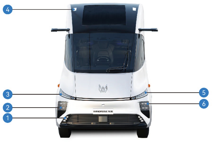
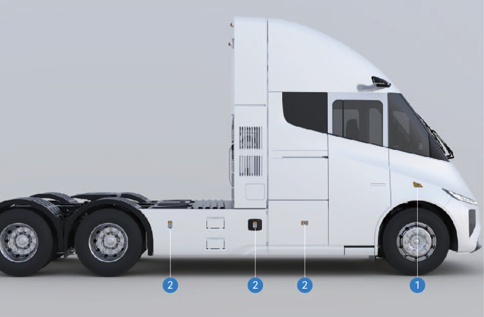
Front fog Lamp, Cornering lamp
High beam
Front indicator lamp, daytime running lamp
Front outline marker lamp
Front parking lamp
Low beam
Side indicator lamp
Side marker combination lamp
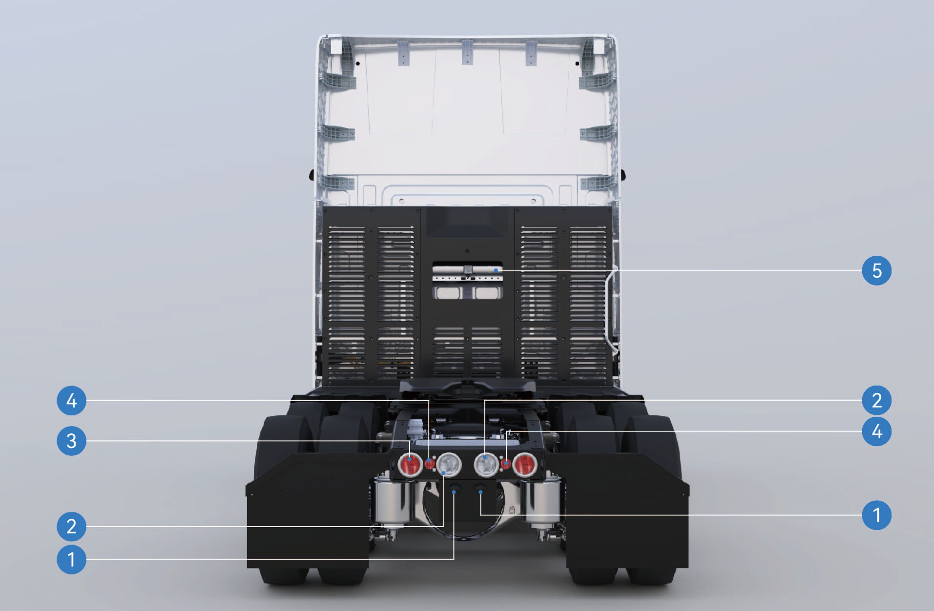
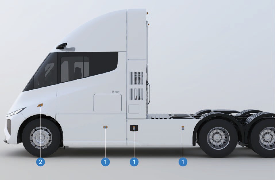
License plate lamp
Reversing lamp
Brake lamp/taillamp/indicator lamp
Rear retro-reflector
Rear working lamp
Side marker combination lamp
Side indicator lamp
|
|
|
|
|
|---|---|---|---|---|
|
|
|
|
|
|
|
|
|
|
|
|
|
2 | |
|
|
|
|
2 |
|
|
|
|
2 |
|
|
|
|
2 |
|
|
|
2 | |
|
|
|
|
2 |
|
|
|
2 | |
|
|
|
2 | |
|
|
|
|
2 |
|
|
|
|
3 |
|
|
9 |
|
1 |
|
|
|
|
6 |
|
|
|
|
|
|---|---|---|---|---|
|
|
|
|
|
|
|
|
|
|
|
|
|
|
|
|
|
|
|
1 |
|
|
|
|
3 |
|
|
|
|
2 |
Data of Protection Device
Technical Data
|
|
|
|
|
|---|---|---|---|---|
|
|
|
|
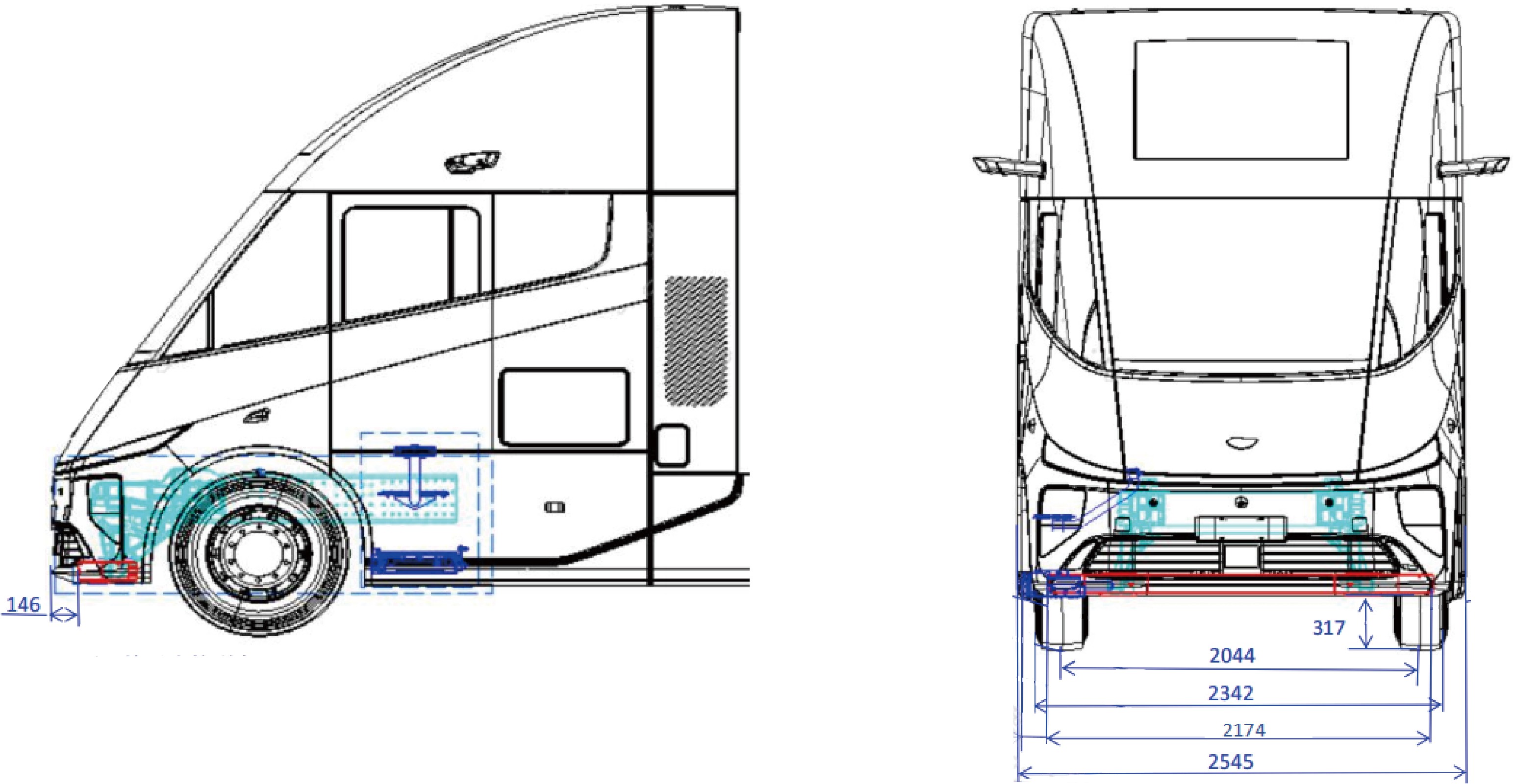
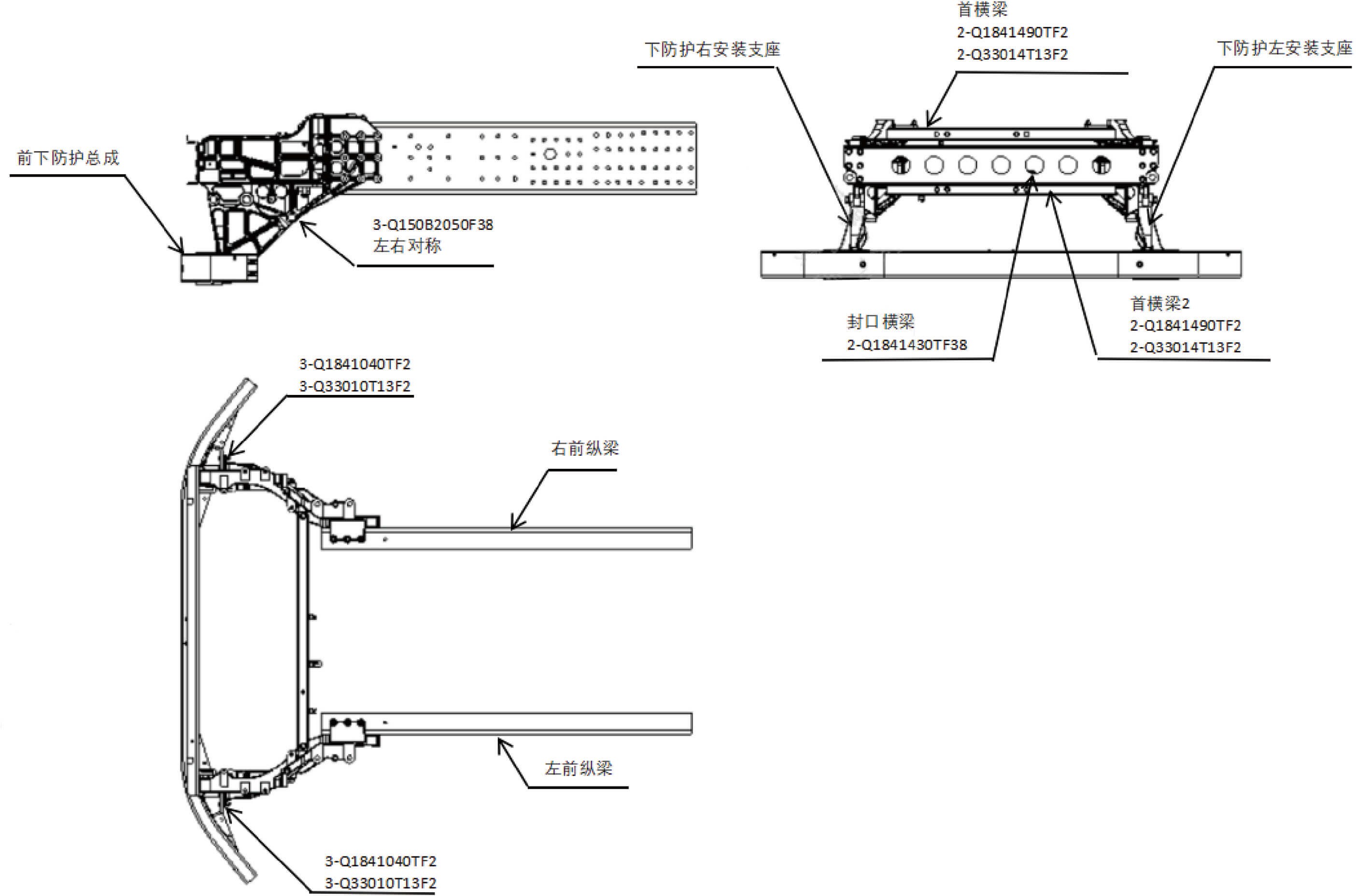
Curb Weight, GVW, Axle Load, Drive Mode
Technical Data
|
|
|
|
|
|
|---|---|---|---|---|---|
|
24,747.1 lb |
|
|
|
|
|
25,077.8 lb |
|
|
|
|
|
26,623.2 lb |
|
|
|
|
|
26,953.9 lb |
|
|
|
|
Barometric Pressure Characterization Data
Technical Data
|
|
|
|
|---|---|---|---|
|
|
|
|