WINDROSE ELECTRIC
R&D & Industrialization
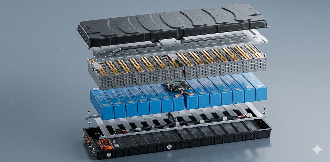
LFP Power Battery CTP Design
Cell-to-pack lithium iron phosphate energy system — integrating cells, BMS, high-voltage components, structural parts, and a liquid thermal-management cold plate into a single enclosure.
176.3kWh
Nominal Energy
766.4V
Nominal Voltage
230Ah
Rated Capacity
1146kg
Pack Weight (±10)
155Wh/kg
Energy Density
IP67
Ingress Protection
01
Module & Pack Topology
- Battery Cover
- Battery Enclosure
- CTP Module
- Module End Plate
- Thermal Management Cold Plate
- BMS
- Insulation Layer
- Thermal Pad
- Thermal Insulation Pad
- High-Voltage Interface
- Low-Voltage Interface
- Coolant Inlet / Outlet
2750mm
Length
1080mm
Width
270mm
Height
705.2kWh
Total Vehicle Energy
Manufactured by SINOEV · 1P238S topology · operating voltage range 595–868.7 V · 1C charge rate · cycle life 4500 (25 °C / SOH 70%).
02
Cell Specifications
| Item | Unit | Design Parameter |
|---|---|---|
| Cell Manufacturer | — | CALB |
| Cell Specification | — | L173F230 |
| Cell Type | — | LFP |
| Cell Dimensions | mm | 173.93 × 53.72 × 204.63 |
| Cell Capacity | Ah | 230 |
| Nominal Voltage | V | 3.22 |
| Voltage Range | V | 2.5 – 3.65 |
| Cell Mass | kg | 4.2 ± 0.08 |
| Energy Density | Wh/kg | 180 |
| Cycle Life | cycles | > 6000 |
| Operating Temperature | ℃ | Discharge −30 – 65 · Charge 0 – 60 |
03
Battery Pack Design Scheme
| Item | Unit | Design Parameter | Remarks |
|---|---|---|---|
| Battery Manufacturer | — | SINOEV | |
| Module & Pack Topology | — | 1P238S | |
| Rated Capacity | Ah | 230 | |
| Nominal Voltage | V | 766.4 | |
| Nominal Energy | kWh | 176.3 | |
| Total Energy | kWh | 705.2 | |
| C-rate | C | 1C | 1C |
| Operating Voltage Range | V | 595 – 868.7 | 25 ℃ |
| Cycle Life | cycles | 4500 | 25 ℃ / SOH 70% |
| Ingress Protection | — | IP67 | |
| Energy Density | Wh/kg | 155 | |
| Weight | kg | 1146 ± 10 |
04
Thermal Management Performance
Thermal Management Design
Operating window −30 – 60 ℃. Liquid cooling power 24 kW; liquid heating power 28 kW.
Low-Temperature Heating
At −20 ℃ ambient, battery heating rate of 19 ℃/h.
Normal-Temp Fast Charging
25 ℃, SOC 20–80% in 38.5 min; max cell temp 42 ℃.
High-Temp Charging
45 ℃, SOC 20–80% in 48 min; max cell temp 45 ℃.
Validated through CFD simulation and DV testing of the LFP battery system across low-temperature heating, normal-temperature charging, and high-temperature charging scenarios.
05
Cell OCV Curve
Charge OCV
Discharge OCV
X: State of Charge (%) · Y: Open-Circuit Voltage (V)