VIN stampingSteering linkage installationRear axle installationTPMS module and bracketBattery pack 1/4 installationBattery pack support (middle layer 2)
VIN stamping / steering / rear axle / battery pack sub-assembly workstation · 6 operations, illustrated edition | Compiled from the original process cards for training and display-board use
VIN stamping
Page 1 Operation steps
Step 10 Verify that the VIN is correct. Step 20 Determine the VIN marking position and clean the surface of the marking area; if the surface to be stamped has obvious scratches or damage, have the quality department confirm it before stamping. Step 30 Move the marking machine to the frame position on the right side of the chassis (see figure) and stamp the VIN; the VIN must be straight and level, not tilted, and clear and legible. Step 40 Clean the VIN surface and make 3 rubbings of the VIN. Step 50 Brush a coat of anti-rust oil over the stamped VIN.
Tools / fixtures
Marking machine
✓ Quality inspection points
Font size 10; engraving depth not less than 0.3 mm
Reference illustrations (click to enlarge)

Steering linkage installation
Page 2 / Sub-assemble first, then install on the vehicle Operation steps
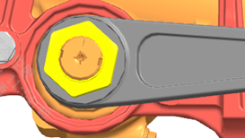
Step 10 First sub-assemble the steering linkage assembly. Step 20 Place the tie rods, relay rod, pitman arm, and idler arm on the steering linkage sub-assembly bench according to the assembly relationship, assemble per the figure, and pre-tighten with pneumatic tools. Step 30 After clamping the steering linkage assembly in a fixture, tighten with a torque-controlled tool to 345 N·m. Step 40 Use the overhead crane to lift the steering linkage assembly onto the lift trolley. Step 50 Use the lift trolley to move the steering linkage to the position below the frame installation point. Step 60 Raise the steering linkage with the trolley and adjust its position relative to the subframe; first align the idler arm with the subframe mounting point, install the fasteners, and leave them loose for now. Step 70 Then align the pitman arm with the EHPS driveshaft (matching the marked lines), install the steering gear nut and tighten to 675 N·m. Step 80 Finally tighten the fasteners securing the idler arm to 210 N·m.
Parts required
Pitman arm ×1
Idler arm ×1
Relay rod ×1
Tie rod ×2
Hex slotted thin nut ×4
Cotter pin ×4
Steering gear nut ×1
Hex flange nut ×4
Hex flange bolt (coarse shank) ×4
Tools / fixtures
Pneumatic tools
torque-controlled tool
overhead crane
lift trolley
pointer-type torque wrench
✓ Quality inspection points
Pre-tightening torque: 345±15 N·m; Idler arm fixing torque: 210±20 N·m; Pitman arm / steering gear nut torque: 675±25 N·m
Reference illustrations (click to enlarge)
Rear axle installation
Page 2 Operation steps
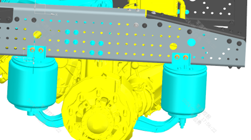
Step 10 Hoist the sub-assembled rear axle onto the axle installation lift trolley and locate it. Step 20 Move the lift trolley to the workstation, push it under the frame, and align the position. Step 30 Use lifting equipment or the overhead crane to raise the rear axle. Step 40 Raise the rear axle to the installation position; first align it with the rear axle mounting holes on the X-link and thread on the nuts (apply thread-locking adhesive), tightening to 700 N·m. Step 50 Then adjust the rear axle position to align the air springs with the mounting holes on the frame and connect them, tightening to 180 N·m; install the left and right air springs symmetrically. Step 60 During assembly, ensure that the air spring upper bracket fits flush against the lower flange surface of the frame rail. Step 70 Use tie-down straps to secure the axle to the frame to prevent it from dropping; during hanging, there must be no interference with brackets or lines; then lower the lift trolley and remove it.
Parts required
Rear axle assembly ×1
Nut M22×1.5 (self-locking) ×4
Hex flange bolt (coarse shank) ×8
All-metal hex flange lock nut ×8
Tools / fixtures
Lifting equipment
overhead crane
lift trolley
pointer-type torque wrench
tie-down strap
✓ Quality inspection points
Tightening torque: 700±50 N·m; Air spring connection torque: 180 N·m; Air spring upper bracket fits flush against the frame rail lower flange (visual)
Reference illustrations (click to enlarge)
TPMS module and bracket
Page 2 / The original document has no detailed text for this operation, only BOM + illustrations Operation steps
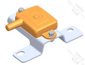
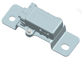
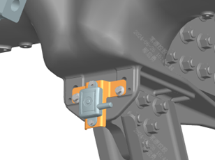
Steps 10-40 Per the parts list, assemble the TPMS repeater, TPMS module bracket 2, TPMS CAN module, and TPMS module bracket in sequence (the original process card only lists the parts here without step-by-step text; refer to the illustrations below). Step 50 Install the TPMS repeater assembly and the TPMS CAN module assembly onto the frame and secure with bolts.
Parts required
TPMS repeater ×1
TPMS CAN module ×1
TPMS module bracket ×1
TPMS module bracket 2 ×1
Hex bolt with spring and flat washer assembly ×2
Type 1 hex nut ×2
Hex flange bolt (coarse shank) ×4
Hex flange bolt with toothed bearing face ×2
All-metal hex flange lock nut ×2
✓ Quality inspection points
Visual inspection
Reference illustrations (click to enlarge)
Battery pack 1/4 installation
Page 5 / Battery pack 1 and battery pack 4 installed symmetrically Operation steps
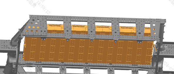
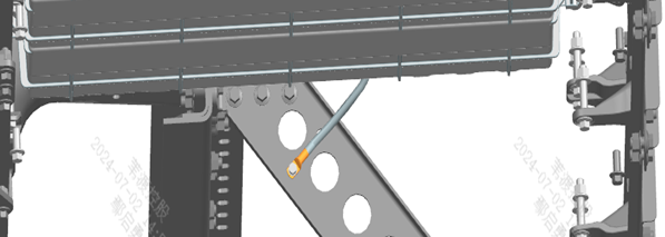
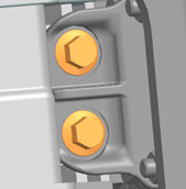
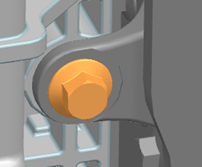
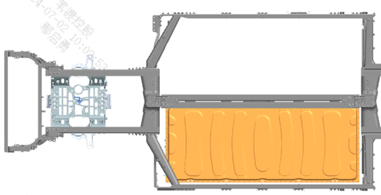
Step 10 Installation of battery pack 1: begin hoisting preparation. Step 20 Position the lift trolley in the right place and move the movable support plate to the center of the ball-transfer pallet so that the adjustment margins are equal all around. Step 30 Loop the lifting slings/straps around the mounting holes at the front and rear ends of the battery pack to ensure balanced, safe lifting. Step 40 Hoist the battery pack onto the lift trolley and locate it on the trolley platform; after checking that the battery pack is placed safely and stably, unhook the slings/straps. Step 50 Use the lift trolley to move the battery pack to the position below the frame installation point. Step 60 Raise the battery pack with the trolley, checking and adjusting the relative position of the battery pack and frame until the battery pack fixing points are 10-20 mm higher than the mounting brackets. Step 70 Install the outer battery support and the outer battery bracket (double-hole) at the positions shown and tighten to 180 N·m. Step 80 Adjust the battery pack laterally so that, once the fixing holes of the battery pack and the supports are aligned, it settles down onto the supports; during this process use the large holes of the front and rear supports to guide the small holes into alignment, then insert bolts to locate. Step 90 Fix the battery pack to the supports per the figure and tighten to 200 N·m. Step 100 Installation of the battery pack 1 ground strap. Step 110 Connect the ground strap at the rear end of the battery pack to the frame; note the installation position and orientation of the conical lock washer — do not install it reversed. Step 120 Scrape the paint off the lap surface between the frame and the conical lock washer; after tightening, apply petroleum jelly over the washer, nut, and the scraped surface. Step 130 Installation of battery pack assembly 4 and its ground strap: positioned symmetrically to battery pack 1; follow Steps 20-120 above.
Parts required
NCM battery pack assembly 1 ×1; Battery pack assembly 4 ×1; Outer battery support (NCM) ×3 each; Outer battery bracket double-hole (NCM) ×2 each; Hex flange bolt (coarse shank) × matched per step; All-metal hex flange lock nut × matched per step; Hex bolt with spring and flat washer assembly ×1; Type 1 hex nut ×1; Conical lock washer ×1
Tools / fixtures
Lift trolley
lifting slings/straps
✓ Quality inspection points
Support tightening torque: 165-195 N·m; Battery pack fixing bolt torque: 200 N·m; The lap surface must have the paint scraped off; apply petroleum jelly after tightening; Visual inspection
Reference illustrations (click to enlarge)
Battery pack support (middle layer 2)
Page 1 Operation steps
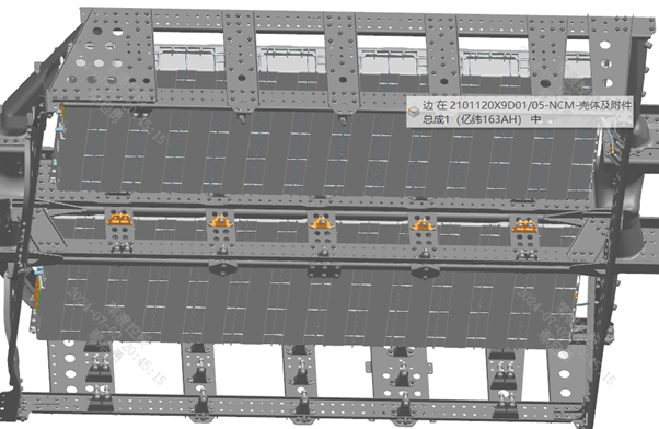
Step 10 The installation method is exactly the same as that of the "battery pack support - middle upper layer"; only the overall position is shifted down by 190 mm.
Parts required
Inner battery support (NCM) ×6
Inner battery support double-hole - front (NCM) ×2
Inner battery support double-hole - rear (NCM) ×2
Hex flange bolt (coarse shank) ×15
All-metal hex flange lock nut ×15
✓ Quality inspection points
Visual inspection
Reference illustrations (click to enlarge)
This page is compiled from process cards ZD104-1010 ~ ZD104-1060 (Anhui Windrose Holdings Co., Ltd.) and is for workshop visual training display only; official production shall follow the controlled process documents.