Install A/C compressorInstall A/C pipingInstall rear air reservoirsSteering fluid reservoir and linesInstall chassis harnessInstall air-spring solenoid valves and bracketsInstall front-end moduleInstall powertrain cooling system pipingBrake line connections 1Install side skirt bracketsInstall rear step assembliesInstall side trim bracketsInstall walkway platform bracketsInstall front lower guard
A/C, Lines, Harness and Exterior Bracket Pre-assembly Station · Illustrated version of 14 operations | Compiled from the original process card for training and display
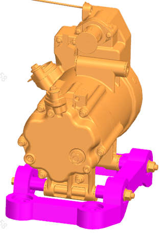
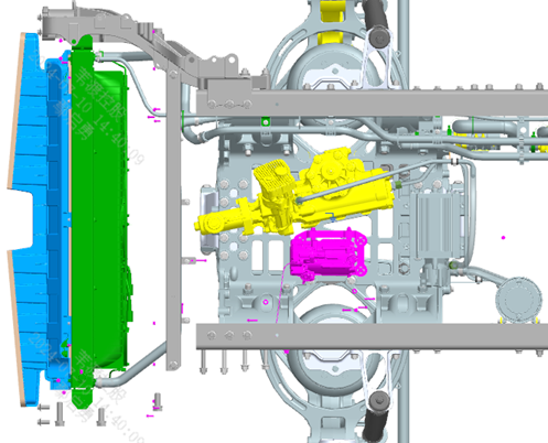
Install A/C compressor
Page 2 / Pre-assemble first, then install on the vehicle | Operation steps
Step 10: Pre-assemble the compressor first — mount the compressor bracket onto the compressor as shown. Step 20: Note the bolt insertion direction; installing the bolts in the wrong direction will affect subsequent compressor servicing. Step 30: Lift the compressor assembly onto the subframe as shown. Step 40: Tighten the 4 connection points of the compressor.
Parts required
A/C compressor assembly ×1
Compressor fixing bolt ×2
Compressor bracket ×1
Hex flange bolt (thick shank) ×4
All-metal hex flange lock nut ×2
Tools / fixtures
Overhead crane
✓ Quality inspection points
Visual inspection: the bolt insertion direction must be carefully verified
Reference illustrations (click to enlarge)
Install A/C piping
Page 3 / Actual steps are on page 3 | Operation steps
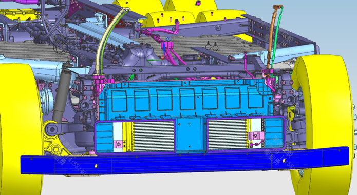
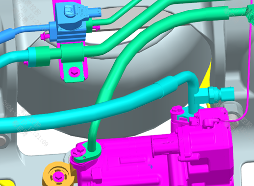
Step 10: Install the A/C piping as shown; ensure the joint clamp plates of the pipe connections are fully seated, tightening torque 10 N·m. Step 20: Finally install the 4 pipes at the top of the front-end module (see the illustration for details).
Parts required
SOV to evaporator line assembly ×1; Left evaporator to SOV line assembly 2 ×1; Right evaporator to SOV valve line assembly (evaporator-pressure end / cooling-evaporator end) ×1 each; Left evaporator to front SOV line assembly 1 (cooling-evaporator end / evaporator-pressure end) ×1 each; Rear evaporator high-pressure pipe assembly ×1; Compressor-cooling three-way pipe ×1; Front evaporator return-line pipe assembly ×1; Return-line adapter pipe ×1; SOV outlet adapter pipe ×1; Pipe clamp φ16-φ9 ×1; Hex flange bolt (thick shank) × matching each interface
Tools / fixtures
Pointer-type torque wrench
✓ Quality inspection points
Tightening torque: 10±1 N·m
Reference illustrations (click to enlarge)
Install rear air reservoirs
Page 4 / Air reservoirs 1 and 2 pre-assembled first, then installed on the vehicle | Operation steps
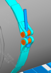
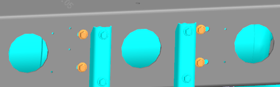
Step 10: Pre-assemble rear air reservoir 1 first (see figure). Step 20: Install the drain valve onto the reservoir. Step 30: Install the plugs and nut seats as shown, paying attention to the installation of the seals; nut seat torque 14 N·m. Step 40: All through holes on the rear air reservoirs must be plugged to prevent foreign matter from entering. Step 50: Secure the reservoir to the bracket with clamp straps; note the state/position of the plugs at both ends — the drain valve of air reservoir 1 must point vertically downward (that of air reservoir 2 vertically upward), and pre-tighten the clamp straps. Step assembly 1-10: Fix air reservoir assembly 1 to the rear end of the frame, using spacer blocks to level between the bracket and the frame. Step assembly 1-30: After the bracket is tightened, adjust the left-right position of the reservoir so that the distances between the two ends of the reservoir and the bracket are symmetrical and the drain valve points vertically downward, then tighten the clamp straps. Step assembly 2: Air reservoir assembly 2 is installed in the same way as assembly 1; when adjusting, use the frame side rail as the datum for symmetry.
Parts required
Air reservoir assembly ×2
Nut seat NG12 ×5
Retaining ring NG12 ×5
Washer NG12 ×5
Drain valve ×2
Plug ×3
O-ring ×3
Seal washer ×3
Bracket ×4
Clamp strap ×4
Pin shaft / pin 1 / pin 2 ×4
Cotter pin ×2
Spacer block ×4
Tools / fixtures
Torque wrench
✓ Quality inspection points
Nut seat tightening torque: 13-16 N·m
Reference illustrations (click to enlarge)
Steering fluid reservoir and lines
Page 4 | Operation steps
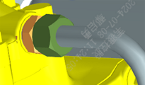
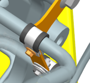
Step 10: Pre-assemble the steering fluid reservoir first (see figure). Step 20: Connect and tighten the reservoir and bracket with 4 bolts. Step 30: Install the steering reservoir assembly onto the frame at the position shown. Step low-pressure line: Install the low-pressure oil line; joint torque — straight-through body joint to low-pressure line: 75 N·m. Step high-pressure line: Install the high-pressure hose; joint torques — ① high-pressure line to straight-through body joint: 110 N·m; ② pump inlet line joint to pump: 125 N·m; ③ straight-through body joint to pump/EPS: 75 N·m. Step inlet/return rubber hoses: Install the inlet rubber hose and return rubber hose, secured with worm-drive hose clamps.
Parts required
Steering fluid reservoir ×1
Steering reservoir bracket ×1
Low-pressure oil line ×1
High-pressure hose ×1
Straight-through body joint ×3
Seal washer ×3
Steering line fixing pipe clamp ×4
Inlet rubber hose ×1
Return rubber hose ×1
Pump inlet line joint ×1
Tools / fixtures
Torque wrench
✓ Quality inspection points
Low-pressure line joint: 75±5 N·m; High-pressure line joint: 110±10 N·m; Pump inlet line joint: 125±5 N·m
Reference illustrations (click to enlarge)
Install chassis harness
Page 10 / Detailed text is on page 1 | Operation steps
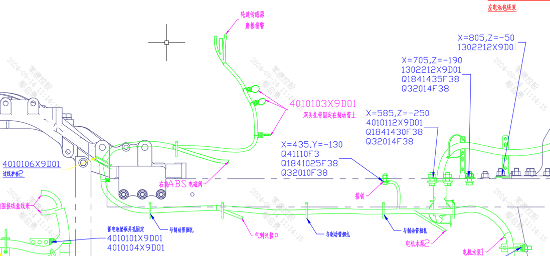
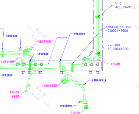
Step 10: Position and route the chassis harness and DC/DC positive cable harness 1 as shown in Figure 2. Step 20: Install the harness ground points as shown (at the positions with serrated washers); scrape off the paint on the grounding mounting surfaces first, then after installation cover them completely with petroleum jelly. Step 30: Secure the chassis harness as shown in Figures 3-9; see Figure 1 for the various cable tie styles. Step 40: Install and connect the left and right battery pack harnesses as shown in Figure 10.
Parts required
Chassis harness ×1; DC/DC positive cable harness 1 ×1; Left battery pack harness ×1; Right battery pack harness ×1; Flat-head cable tie 1/2 × as required; Interlocking cable tie ×6; Round-head cable tie ×8; Pine-tree cable tie ×16
✓ Quality inspection points
Grounding surfaces must have the paint scraped off and be covered with petroleum jelly
Reference illustrations (click to enlarge)
Install air-spring solenoid valves and brackets
Page 2 / One set on each side | Operation steps
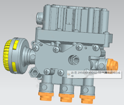
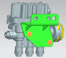
Step 10: Install the 4 straight-through joints onto the air-spring solenoid valves and tighten; tightening torque — left side 14 N·m / right side 13 N·m. Step 20: Install the solenoid valve bracket onto the valve and secure with M8×60 bolts. Step 30: Install the solenoid valve assembly onto the inside of the left front frame side rail as shown (the right side is installed on the inside of the left rear side rail), securing with bolts and nuts; note that the bracket must not squeeze the harness and air lines on the inside; the fasteners are shared with the cab mount, and when applying the tightening torque the 4 cab mount fasteners must be tightened diagonally. Step 40: Tighten the fasteners, torque 180 N·m. Step 45: All pipe interfaces must be effectively covered with tape or plugs.
Parts required
Air-spring solenoid valve assembly (left/right) ×1 each; Straight-through joint ×4 (per side); Air-spring solenoid valve bracket ×1 (per side); Hex flange bolt with serrated bearing face ×2; Hex flange bolt (thick shank) ×2; All-metal hex flange lock nut ×2
Tools / fixtures
Preset torque wrench NB-300; Torque wrench
✓ Quality inspection points
Straight-through joint tightening torque: 13-14 N·m; Fastener tightening torque: 180±15 N·m
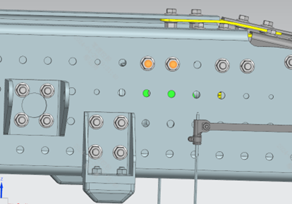
Reference illustrations (click to enlarge)
Install front-end module
Page 4 | Operation steps
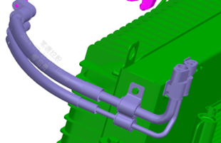
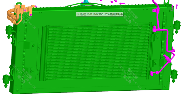
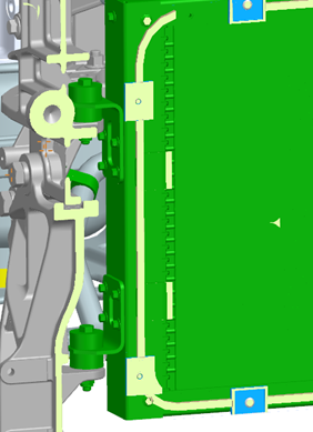
Step 10: Pre-assemble the front-end module first: install the condenser inlet/outlet pipe assembly. Step 20 (right side): Install the right-side piping (right evaporator to SOV valve line assembly 2). Step 20 (air guide): Install the air guide assembly, secured with 10 bolts. Step 30: Lift the front-end module assembly to the position shown and secure it to the frame using the fasteners supplied with the front-end module. Step 40: Note the installation position of the rubber spacer blocks; there are 4 connection points in total, symmetrical left and right.
Parts required
Front-end module ×1
Condenser inlet/outlet pipe assembly ×1
Right evaporator to SOV valve line assembly 2 ×1
Air guide assembly ×1
Hex flange bolt (thick shank) × matching each interface
Tools / fixtures
Overhead crane
✓ Quality inspection points
Visual inspection: the rubber spacer block positions and left-right symmetry must be carefully verified
Reference illustrations (click to enlarge)
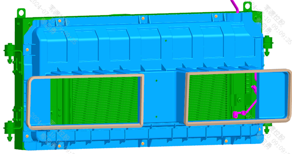
Install powertrain cooling system piping
Page 10 / Front, middle and rear pipe sections | Operation steps
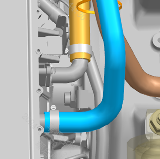
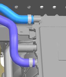
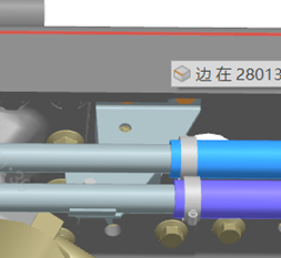
Step 10: Pre-assemble the rear pump outlet pipe first (see figure). Step 20: Connect the single-end of the outlet nylon pipe to the rubber hose and tighten, torque 7 N·m; note that the clamp bolt head direction must be consistent with the other end of the rubber hose. Step 30: Connect and secure the inter-pump rubber hose to the two pumps, clamp tightening torque 4 N·m. Step 50 (front section): Install the rear pump outlet pipe assembly onto the rear pump as shown in the enlarged view at position A. Step 60 (front section): Install as shown in the enlarged views at positions B, C, D, E and F (front-end module inlet/outlet lines, long vent pipe, various fixing pipe clamps, etc.). Step 70: Install as shown in the M-direction and N-direction views. Step 80: Install as shown in the enlarged view at position G. Step 90 (middle section): Install as shown (make-up water nylon pipe 2, M & MCU inlet nylon pipe 1, M1 inlet nylon pipe, front-end module inlet nylon pipe 2, etc.). Step 100 (middle section): Install as shown in the enlarged view at position H. Step 110 (rear section): Install as per 'Powertrain cooling system piping installation at the rear section of the frame (1)' (combined three-way hard pipe, middle/rear axle combined hard pipe). Step 120 (rear section): Install as per 'Powertrain cooling system piping installation at the rear section of the frame (2)' (rear axle inlet rubber hose 1, middle/rear axle return rubber hose, M1/M3 inlet rubber hoses, etc., all with protective braiding).
Parts required
Rear pump outlet rubber hose ×1; Pump outlet nylon pipe ×1; Inter-pump rubber hose ×1; Front-end module inlet/outlet nylon pipe/rubber hose × matching each section; Long vent pipe ×1; Combined three-way hard pipe ×1; Middle/rear axle combined hard pipe ×1; Various fixing pipe clamps (single/two/three-hole) × matching each section; Rubber hoses with protective braiding (rear axle / M1 / M3 inlet, middle/rear axle return, etc.) × matching each section
Tools / fixtures
Torque wrench
✓ Quality inspection points
Outlet nylon pipe joint torque: 6-8 N·m; Inter-pump rubber hose clamp torque: 3-4 N·m
Reference illustrations (click to enlarge)
Brake line connections 1
Page 5 | Operation steps
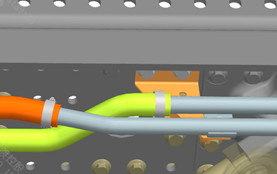
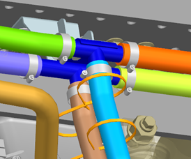
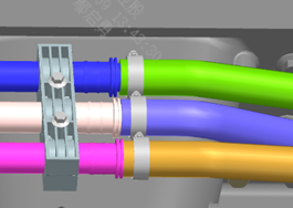
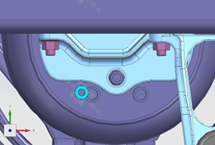
Step 10: Connection of the brake line bundle to the air suspension electronic control unit: install the pressure sensors, nut seats and plugs on the air spring upper bracket as shown in Figure 1; nut seat tightening torque 14 N·m, pressure sensor 26 N·m. Step 20: Connect the brake line bundle to the air springs and the brake chambers of the middle/rear axles as shown in Figure 2. Steps 30-40: Air-spring solenoid valve connections: connect the lines to the interfaces of the front and rear air-spring solenoid valves as shown in Figure 3. Steps 50-60: Connection of the brake line bundle to the rear air reservoirs: connect as shown in Figure 4; 4 interfaces on the left side, 1 on the right; distinguish the service and parking reservoir interfaces by the port markings on the line bundle and do not mix them up. Step 70: Fix the brake lines as shown in the figures, ensuring the lines are smooth, without sagging or kinking; minimum clearance to moving parts no less than 20 mm; fixing spacing of the lines no greater than 300 mm.
Parts required
Pressure sensor assembly ×3
Plug ×3
Nut seat NG8 ×10
Retaining ring NG8 ×10
Washer NG8 ×10
Brake hose assembly ×2
T-type joint ×2
Seal washer ×2
Hex thin nut for pipe joints ×2
Test joint ×2
Tools / fixtures
Torque wrench
✓ Quality inspection points
Nut seat tightening torque: 14 N·m; Pressure sensor tightening torque: 26 N·m; Line fixing spacing: no greater than 300 mm; Minimum clearance to moving parts: no less than 20 mm
Reference illustrations (click to enlarge)
Install side skirt brackets
Page 1 | Operation steps
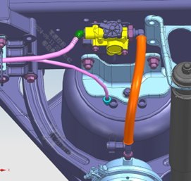
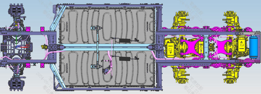
Step 10: Install the left-side side skirt mounting brackets as shown. Step 20: Install the right-side skirt mounting brackets symmetrically to the left side.
Parts required
Side skirt bracket ×6
Small-hole mounting bracket on the skirt upper part ×4
Lower skirt mounting bracket ×8
Hex flange bolt ×12
Hex flange nut ×12
Hex flange bolt (thick shank) ×24
Hex flange nut ×24
Tools / fixtures
Pointer-type torque wrench
✓ Quality inspection points
Tightening torque: 700±50 N·m
Reference illustrations (click to enlarge)

Install rear step assemblies
Page 1 | Operation steps
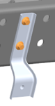
Step 10: Install the 2 rear step assemblies (upper and lower) on the right side of the frame as shown. Step 20: Install the left-side rear step assemblies symmetrically to the right side (the original text of step 20 lacks specific wording; install symmetrically per the parts list and illustrations).
Parts required
Rear step assembly ×2
Rear step mounting base ×4
Hex flange bolt (thick shank) ×8
Hex flange nut ×8
Tools / fixtures
Pointer-type torque wrench
✓ Quality inspection points
Tightening torque: 700±50 N·m
Reference illustrations (click to enlarge)
Install side trim brackets
Page 2 | Operation steps
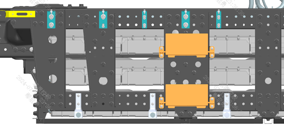
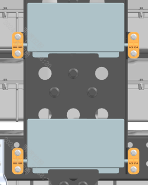
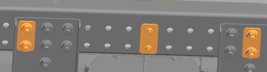
Step 10: Install the left-side side trim mounting brackets as shown. Step 20: Fix the nut plates to the frame with bolts, pre-tightening first. Step 30: When installing the brackets, keep the brackets as vertical as possible without tilting. Steps 40-50: Install the right-side side trim mounting brackets as shown, symmetrical to the left side; additionally install the right-side front mounting bracket on the right side.
Parts required
Nut plate 1 ×4; Nut plate 2 ×2; Lower mounting bracket of the side lower trim panel ×1; Lower skirt mounting bracket ×5; Right-side front mounting bracket ×1; Hex flange bolt (thick shank) × matching each step; Hex flange nut × matching each step
Tools / fixtures
Pointer-type torque wrench
✓ Quality inspection points
Tightening torque: 700±50 N·m; Brackets must be installed vertical and not tilted
Reference illustrations (click to enlarge)

Install walkway platform brackets
Page 1 | Operation steps
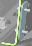
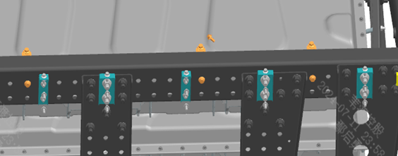
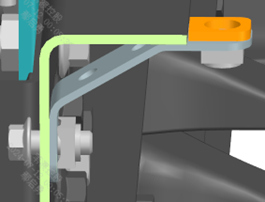
Step 10: Install the 3 walkway platform brackets on the left side as shown. Step 20: Install the 3 walkway platform brackets on the right side symmetrically to the left. Step 30: Note: the upper surface of the yellow spacer plates must be flush with the upper surface of the frame rail flange.
Parts required
Walkway fixing bracket ×6
Hex flange bolt (thick shank) ×6
Tools / fixtures
Pointer-type torque wrench
✓ Quality inspection points
Tightening torque: 700±50 N·m; The upper surface of the yellow spacer plates must be flush with the frame rail flange
Reference illustrations (click to enlarge)
Install front lower guard
Page 1 | Operation steps
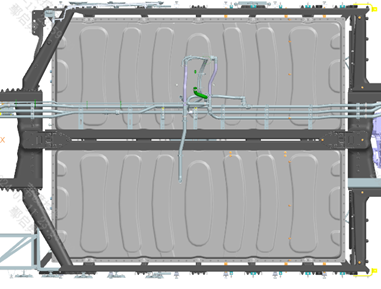
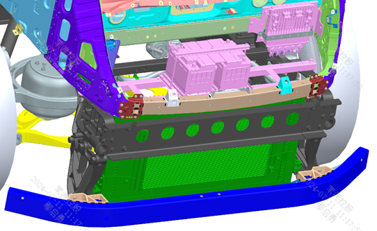
Step 10: Install the front lower guard assembly as shown; note: the side of the lower guard with fewer fixing holes faces up and the side with more holes faces down — do not install it upside down. Step 20: Install the right side as shown; install the left side symmetrically to the right. Step 30: Fastener tightening torque 70 N·m.
Parts required
Front lower guard assembly ×1
Hex flange bolt ×6
All-metal hex flange lock nut ×6
Tools / fixtures
Pointer-type torque wrench
✓ Quality inspection points
Tightening torque: 60-80 N·m (first-part / daily re-check)
Reference illustrations (click to enlarge)
This page is compiled from the ZD108-1010 to ZD108-1150 process cards (Anhui Windrose Holdings Co., Ltd.) and is for workshop visual training only; official production shall follow the controlled process documents.