Install the cab (drop-in)Connect steering gear and columnBrake line connections 2A/C piping connections (front compartment)Install the integrated frame (drop-in)Install fender bracket assembliesInstall headlamps and bracketsInstall front combination lampsInstall fenders
Cab Drop-in Installation / Front Appearance Pre-assembly Station · Illustrated version of 9 operations | Compiled from the original process card for training and display
Install the cab (drop-in)
Page 2 | Operation steps
Step 10: Lift the cab above the chassis; as shown, first align the front locating points with the frame locating points using a pry bar, then align the rear locating points. Step 20: Connect and tighten the chassis to the body with the fasteners as shown, torque 310 N·m. Step 30: Finally tighten the bolts connecting the left and right cab mounts 2 and 3 to the frame, torque 200 N·m.
Parts required
Hex flange bolt with serrated bearing face ×8
Hex flange bolt (thick shank, fine thread) ×2
Tools / fixtures
Pry bar
Overhead crane
✓ Quality inspection points
Cab mount connection torque: 200±10 N·m; Chassis-to-body connection torque: 310±10 N·m
Reference illustrations (click to enlarge)
Connect steering gear and column
Page 1 | Operation steps
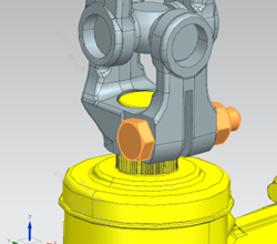
Step 10: After the cab is dropped onto the chassis, align the lower universal joint of the steering column with the steering gear spline as shown. Step 20: Once face A and face B are basically flush, insert the bolt and nut and tighten, tightening torque 53 N·m. Step 30: After tightening, check again whether faces A and B are flush; if the deviation is greater than 2 mm, loosen the bolt, check whether the limit bolt is seated in the slot, and reinstall.
Parts required
Hex head bolt ×1
All-metal hex flange lock nut ×1
Tools / fixtures
Torque wrench
✓ Quality inspection points
Tightening torque: 53±7 N·m; The flush deviation of faces A/B must not exceed 2 mm
Reference illustrations (click to enlarge)
Brake line connections 2
Page 1 | Operation steps
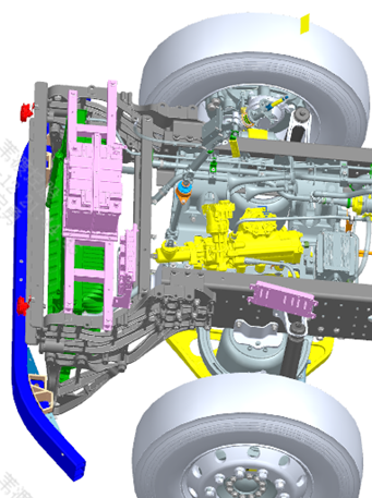
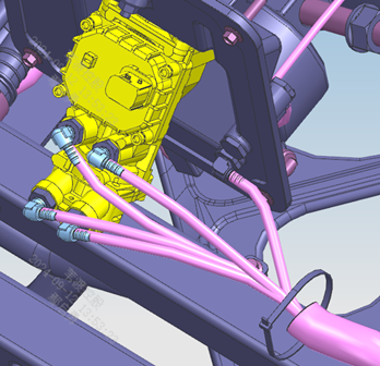
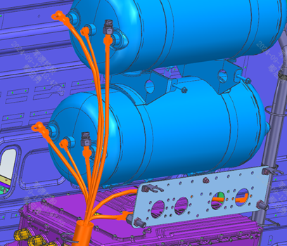
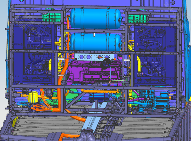
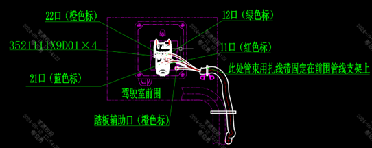
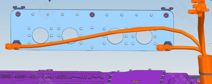
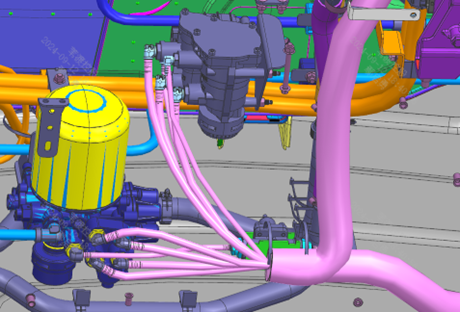
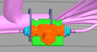
Step 10: Connect the brake lines of the foot valve and the seat transition air line as shown in Figure 1, securing them with cable ties. Step 20: Connect the air lines of the air reservoirs on the integrated frame and the trailer air line couplings as shown in Figure 2; connect the air lines of the air dryer, trailer control module and overflow valve; secure the lines with cable ties. Step 30: All air lines must be smooth, without sagging or kinking; minimum clearance to moving parts no less than 20 mm; line fixing spacing no greater than 300 mm.
Parts required
Flat-head cable tie 1 × as required
✓ Quality inspection points
Line fixing spacing: no greater than 300 mm; Minimum clearance to moving parts: no less than 20 mm
Reference illustrations (click to enlarge)
A/C piping connections (front compartment)
Page 2 / Actual steps are on page 2 | Operation steps
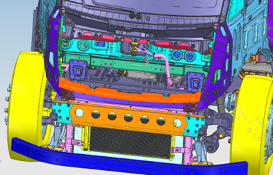
Step 10: The A/C piping connections inside the front compartment are shown in the figure above. Step 20: The A/C piping connections under the cab are shown in the figure on the left. Step 30: Check the refrigerant charging ports on the A/C high- and low-pressure lines.
Parts required
Hex flange bolt (thick shank) ×4
✓ Quality inspection points
Visual inspection: the condition of the refrigerant charging ports must be checked
Reference illustrations (click to enlarge)
Install the integrated frame (drop-in)
Page 3 | Operation steps
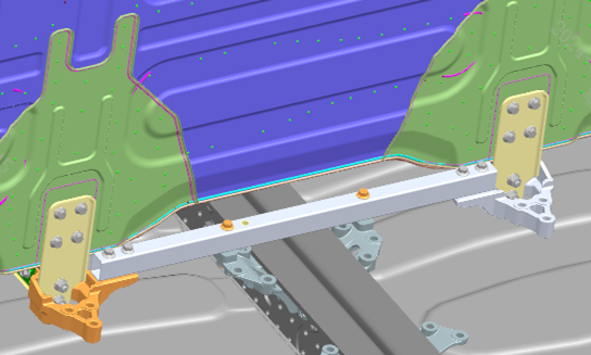
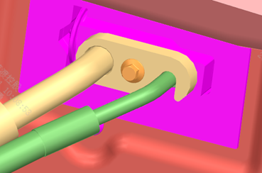
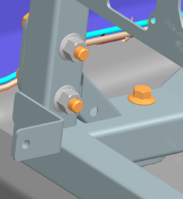
Step 10: Install the outer lap castings: pre-assemble first without tightening the bolts. Step 10 (frame): Lift the integrated frame assembly above the chassis. Step 20: Position the integrated frame on the chassis assembly as shown; align the front face of the front lower cross member of the integrated frame with the 2 locating surfaces, and center the rear locating holes in the Y direction. Step 30: Connect and pre-tighten the 'integrated frame to the middle lap parts'. Step 40: Connect and pre-tighten the 'integrated frame to cab mount 4' (the figure shows the left-side position; the right side is symmetrical to the left). Step 50: Connect and pre-tighten the 'integrated frame to the outer lap parts' (the figure shows the left-side position; the right side is symmetrical to the left). Step 60: Tighten all of the above parts; the torque of the cab mount 4 fasteners is 310 N·m. Step 70: Finally tighten the fasteners of the integrated frame outer lap parts to the chassis. Note: during drop-in installation the harness and line bundles pass through the inside of the frame; when lifting, keep clearance between the sides and the body-in-white to avoid knocks and scratches.
Parts required
Outer lap casting 1/2 ×2 each; Hex flange bolt (thick shank) × matching each step; Hex flange nut × matching each step; Hex flange bolt with serrated bearing face (fine thread) ×6
Tools / fixtures
Overhead crane
✓ Quality inspection points
Cab mount 4 connection torque: 310±10 N·m; Avoid knocks and scratches against the body-in-white during lifting
Reference illustrations (click to enlarge)
Install fender bracket assemblies
Page 1 | Operation steps
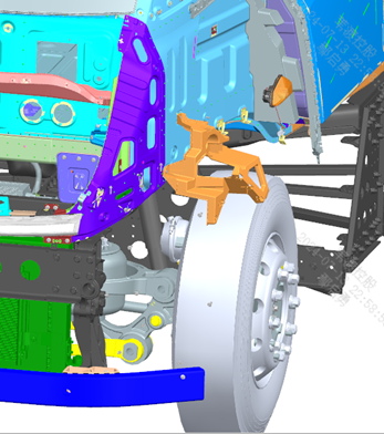
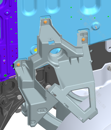
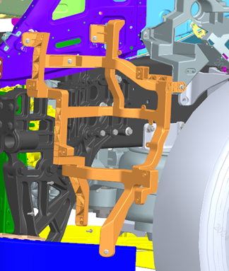
Step 10: Install the left fender bracket assembly as shown. Step 20: Install the right fender bracket assembly symmetrically to the left side.
Parts required
Left fender bracket assembly ×1
Right fender bracket assembly ×1
Hex flange bolt (thick shank) ×6
Tools / fixtures
Torque wrench
✓ Quality inspection points
Tightening torque: 23±3 N·m
Reference illustrations (click to enlarge)
Install headlamps and brackets
Page 2 | Operation steps
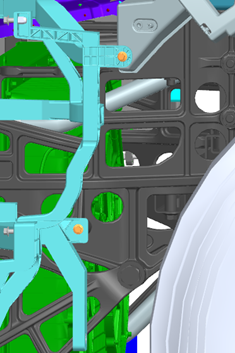
Step 10: Before installation, first confirm that the 'fender bracket assemblies have been installed'; install the left headlamp bracket as shown, tightening torque 8 N·m — the torque must be strictly controlled to avoid damaging the headlamp fixing tabs. Step 20: Install the right headlamp bracket symmetrically to the left side. Step 10 (lamp body): Install the left headlamp as shown. Step 30 (lamp body): Install the right headlamp bracket symmetrically to the left side.
Parts required
Left headlamp bracket ×1
Right headlamp bracket ×1
Left headlamp ×1
Right headlamp ×1
Hex flange bolt ×20
Tools / fixtures
Torque wrench
✓ Quality inspection points
Bracket tightening torque: 8±1 N·m (be careful to avoid damaging the lamp fixing tabs)
Reference illustrations (click to enlarge)
Install front combination lamps
Page 1 | Operation steps
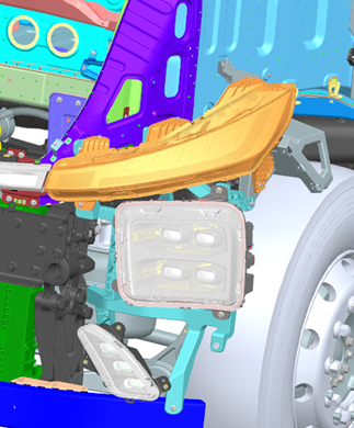
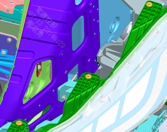
Step 10: Install the left front combination lamp as shown. Step 20: Install the right front combination lamp symmetrically to the left side.
Parts required
Left front combination lamp ×1
Right front combination lamp ×1
Hex flange bolt (thick shank) ×10
Tools / fixtures
Torque wrench
✓ Quality inspection points
Tightening torque: 23±3 N·m
Reference illustrations (click to enlarge)
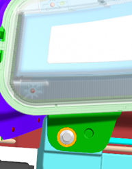
Install fenders
Page 7 / Each side has two parts: pre-assembly + installation | Operation steps
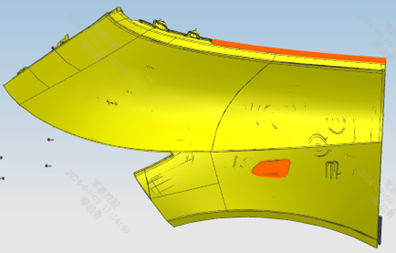
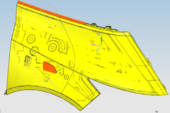
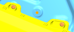
Step 10: Pre-assemble the left fender: fix the left turn signal lamp to the fender as shown — first align the 2 locating features during installation; and fix the harness connector to the position shown. Step 20: Snap the filler block into the corresponding position on the fender. Step 25: Install the fender trim strip at the position shown, noting that the beveled end faces forward. Step 30: Install the left fender: install the left fender connection frame as shown, first aligning the locating pins with the holes, then tighten with the fasteners. Step 40: Take the left fender assembly and first engage the rear and upper sides onto the left fender connection frame assembly and the upper frame. Step 50: Then press the front end of the left fender, at the area where it mates with the combination lamp, outward and snap it onto the front combination lamp. Step 60: Fix the left fender to the body-in-white with 5 bolts, and finally secure the fender assembly to the connection frame with 1 self-tapping screw. Step right side, same principle: the pre-assembly and installation steps for the right fender are completely symmetrical to the left; follow steps 10-60 above.
Parts required
Left/right fender assembly ×1 each; Left/right fender filler block ×1 each; Left/right turn signal lamp ×1 each; Left/right fender trim strip ×1 each; Left/right fender connection frame assembly ×1 each; Left/right fender upper frame ×1 each; Front cover opening handle assembly ×1; Fender cover panel body ×1; Hex flange bolt (thick shank) × matching each step; Cross-recessed pan-head self-tapping screw with flat washer assembly ×12
✓ Quality inspection points
Tightening torque: 23±3 N·m; The locating pin/hole alignment and the 2 turn signal lamp locating features must be carefully verified
Reference illustrations (click to enlarge)
This page is compiled from the ZD110-1010 to ZD110-1120 process cards (Anhui Windrose Holdings Co., Ltd.) and is for workshop visual training only; official production shall follow the controlled process documents.