Fill battery coolantFill motor coolantCharge A/C refrigerantFill windshield washer fluidInstall nameplatesInstall steering wheel
Filling, Nameplates, Steering Wheel Pre-assembly Station · Illustrated version of 6 operations | Compiled from the original process card for training and display
Fill battery coolant
Page 1 | Operation steps
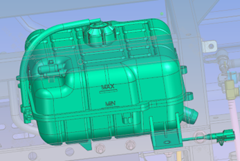
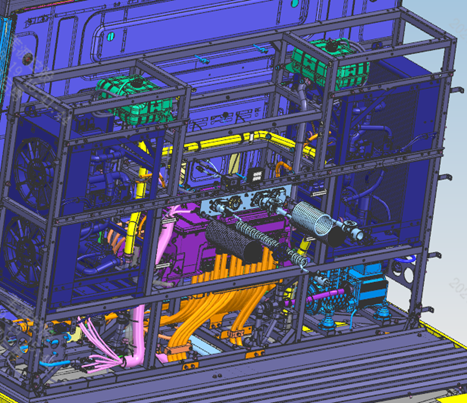
Step 10: Fill using the filling container; the fill port location is as shown. Step 20: Fill coolant until the reservoir is full to just below overflowing. Step 30: After the vehicle's high-voltage system is powered on, operate the driver's screen to start the coolant circulation pump and top up the coolant; after the pump has run for 5-8 minutes, the level should be between the MAX and MIN marks, in the upper-middle position. Step 40: Check the fluid level again after the vehicle dynamic road test; requirements are the same as above.
Parts required
Coolant (-45°C) × approx. 37 L for ternary lithium / approx. 27 L for lithium iron phosphate
Tools / fixtures
Filling container
✓ Quality inspection points
The fluid level must be in the upper-middle position between the MAX and MIN marks
Reference illustrations (click to enlarge)
Fill motor coolant
Page 1 | Operation steps
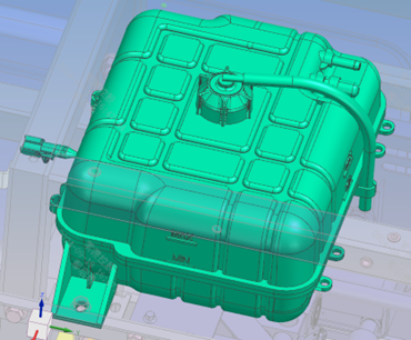
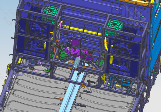
Step 10: Fill using the filling container; the fill port location is as shown. Step 20: Fill coolant until the reservoir is full to just below overflowing. Step 30: After the vehicle's high-voltage system is powered on, operate the driver's screen to start the coolant circulation pump and top up the coolant; after the pump has run for 5-8 minutes, the level should be between the MAX and MIN marks, in the upper-middle position. Step 40: Check the fluid level again after the vehicle dynamic road test; requirements are the same as above.
Parts required
Coolant (-45°C) × approx. 30 L for 3-motor / approx. 35 L for 4-motor
Tools / fixtures
Filling container
✓ Quality inspection points
The fluid level must be in the upper-middle position between the MAX and MIN marks
Reference illustrations (click to enlarge)
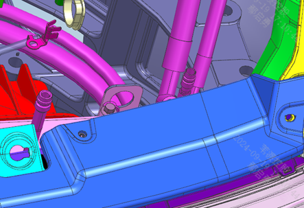
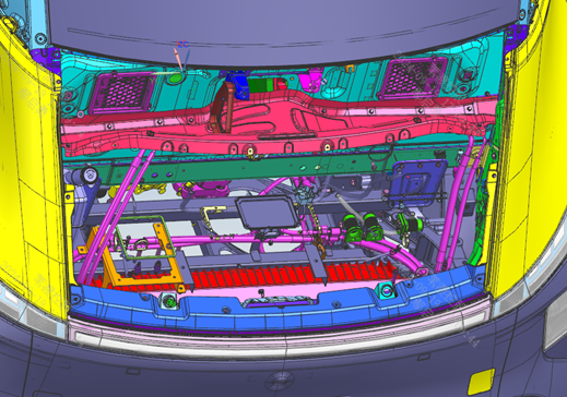
Charge A/C refrigerant
Page 1 | Operation steps
Step 10: Turn on the equipment control power; the machine enters the startup screen. On the interface, select 'Vehicle model parameter recall' and choose the corresponding vehicle model; after selection, return to the 'System monitoring screen' to monitor the charging process. Step 20: Unscrew the caps on the A/C evaporator inlet and outlet pipes; connect the blue hose of the equipment charging gun to the evaporator outlet pipe (low-pressure line) and tighten the joint; connect the red hose to the evaporator inlet pipe (high-pressure line) and tighten the joint. Step 30: Refrigerant charging procedure: connect the charging port → start the equipment → first evacuation → pressure-hold leak test → second evacuation → charging → complete; the pressure-hold leak test must last no less than 30 seconds, and during evacuation the absolute pressure of the lines must not exceed 0.01 MPa. Step 40: After charging is complete, remove the charging gun and screw the caps back onto the A/C evaporator inlet and outlet pipes.
Parts required
R134a refrigerant ×850
g
Tools / fixtures
A/C refrigerant charging equipment
✓ Quality inspection points
Pressure-hold leak test time: ≥30 s; Absolute pressure of lines during evacuation: ≤0.01 MPa
Reference illustrations (click to enlarge)
Fill windshield washer fluid
Page 1 | Operation steps
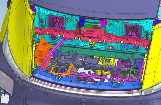
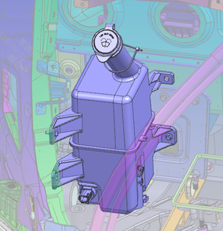
Step 10: Fill using the filling container; the fill port location is as shown. Step 20: Open the fill port cap, fill, then close the fill port cap.
Parts required
Windshield washer fluid ×3.5
L
Tools / fixtures
Filling container
✓ Quality inspection points
Visual inspection
Reference illustrations (click to enlarge)
Install nameplates
Page 2 | Operation steps
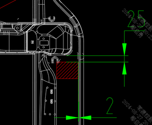
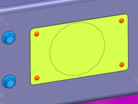
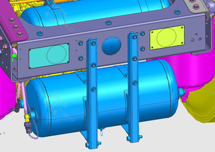
Step 10: Affix the vehicle nameplate as shown; before affixing, wipe the bonding surface of the cab clean with a soft cloth and confirm it is free of oil and dust before bonding. Step 20: The nameplate must be bonded in a vertical orientation with a flat surface — no wrinkles, lifting edges or bubbles. Step 30: Rivet the rear marker plate and the interchangeability nameplate to the rear end of the frame at the positions shown.
Parts required
Rear marker plate ×1
Interchangeability nameplate ×1
Vehicle nameplate ×1
Brake system parameter label ×1
Open-end flat round-head blind rivet ×8
✓ Quality inspection points
The bonding surface must be clean and free of oil and dust; The nameplate must be vertical and flat, without wrinkles, lifting edges or bubbles
Reference illustrations (click to enlarge)
Install steering wheel
Page 1 / The original file has no separate illustration for this operation | Operation steps
Step 10: Check the orientation of the steering column spline and the steering wheel spline. Step 20: Mount the steering wheel assembly onto the steering column; install the flat washer and hex thin nut in sequence, pre-tightening but not fully tightening for now; do not install the horn cover yet — place it somewhere in the cab where it will not be knocked or scratched. Step 30: During the four-wheel alignment process, with the front wheels straight, adjust the steering wheel to the centered position, then tighten the nut to 60 N·m. Step 40: Finally snap the horn cover onto the steering wheel.
Parts required
Steering wheel assembly ×1
Hex thin nut ×1
Flat washer ×1
Driver horn cover assembly ×1
Tools / fixtures
Torque wrench
✓ Quality inspection points
Tightening torque: 60±5 N·m
This page is compiled from the ZD113-1010 to ZD113-1080 process cards (Anhui Windrose Holdings Co., Ltd.) and is for workshop visual training only; official production shall follow the controlled process documents.