Cab suspension mount installationRear shock absorber upper bracket installationRear tandem axle jounce bumper installationX-link installationTorque rod bracket installationDifferential lock solenoid valve installationL-shaped bracket (chassis wiring harness)Brake line installationA/C line bracketFront shock absorber upper bracket installationSubframe lower connecting bracket installationLower guard mounting bracket
Chassis / rear tandem axle sub-assembly workstation · 12 operations, illustrated edition | Compiled from the original process cards for training and display-board use
Cab suspension mount installation
Page 1 Operation steps
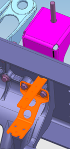
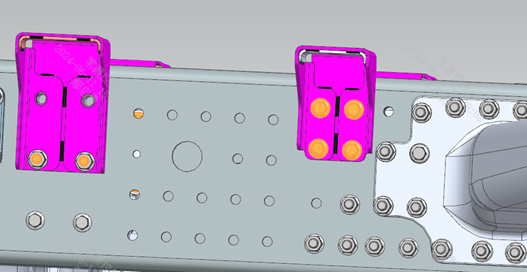
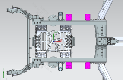
Step 10 Install the Suspension Mount Bracket 2 assembly and the Suspension Mount Bracket 3 assembly (1 each) on the left side of the frame at the positions shown in the figure. Step 20 Before tightening the bolts, use the gauge block to control the height difference between the top surface of the suspension mount bracket and the top surface of the frame rail; set it at 36.9 mm. Step 30 Install the right-side suspension mount bracket symmetrically to the left side. Step 40 The two fixing points above the left-side Suspension Mount Bracket 2 assembly will be installed together when the air-spring solenoid valve is fitted; all four fixing points on the right side are to be fully installed at this workstation. Step 50 Tighten the fasteners to 200 N·m.
Parts required
Suspension Mount Bracket 2 assembly ×2
Suspension Mount Bracket 3 assembly ×2
Hex flange bolt (coarse shank, fine thread) ×10
Hex flange nut ×14
Water line retaining bracket 2 ×1
Water line retaining bracket 3 ×1
Tools / fixtures
Torque wrench
gauge block
✓ Quality inspection points
Tightening torque: 200±10 N·m
Reference illustrations (click to enlarge)
Rear shock absorber upper bracket installation
Page 1 Operation steps
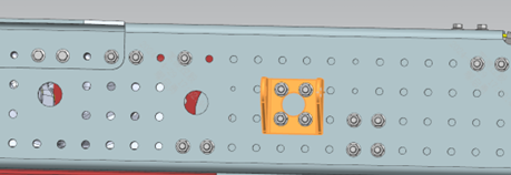
Step 10 Install the left shock absorber upper bracket of the rear axle onto the frame at the position shown. Step 20 Install the right shock absorber upper bracket of the rear axle symmetrically to the left side. Step 30 Install the left shock absorber upper bracket of the middle axle onto the frame. Step 40 Install the right shock absorber upper bracket of the middle axle symmetrically to the left side. Step Tightening Use the preset torque wrench (NB-300) to tighten the fasteners to 180±15 N·m.
Parts required
Rear shock absorber upper bracket ×4
Hex flange bolt (rear axle) ×8
Hex flange bolt (middle axle) ×8
All-metal hex flange lock nut ×16
Tools / fixtures
Preset torque wrench NB-300
✓ Quality inspection points
Tightening torque: 180±15 N·m; Visual inspection
Reference illustrations (click to enlarge)

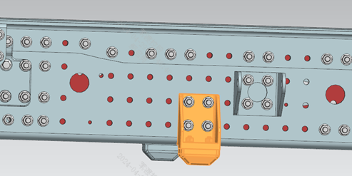
Rear tandem axle jounce bumper installation
Page 1 Operation steps
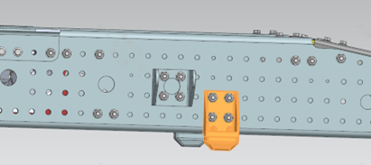
Step 10 Install the left jounce bumper of the rear axle onto the frame at the position shown. Step 20 Install the right jounce bumper of the rear axle symmetrically to the left side. Step 30 Install the left jounce bumper of the middle axle onto the frame. Step 40 Install the right jounce bumper of the middle axle symmetrically to the left side.
Parts required
Jounce bumper assembly ×4
Hex flange bolt (rear axle) ×8
Hex flange bolt (middle axle) ×8
All-metal hex flange lock nut ×16
✓ Quality inspection points
Visual inspection
Reference illustrations (click to enlarge)
X-link installation
Page 1 Operation steps
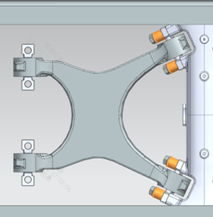
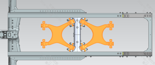
Step 10 Install the X-type control arm above the middle axle at the position shown. Step 20 Use the lifting sling to hoist the X-type control arm to the installation position — keep the control arm roughly level during lifting, with the side bearing the material code facing up. Step 30 Before installing the fasteners, check the threaded holes of the tube beam for foreign matter; run the fasteners in 2-3 turns by hand first, then tighten with a tool; apply Kexinxin 1271 thread-locking adhesive to the engaged threads of the bolts. Step 40 Use the preset torque wrench set to 700 N·m. Step 50 Install the X-type control arm above the rear axle symmetrically in the same manner, aligned with the tube beam position.
Parts required
X-type control arm assembly ×2; Bushing ×8; Hex flange bolt M22×1.5 ×8
Tools / fixtures
Lifting sling
pointer-type torque wrench
✓ Quality inspection points
Tightening torque: 700±50 N·m (recheck with pointer-type torque wrench)
Reference illustrations (click to enlarge)
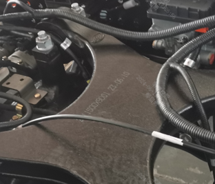
Torque rod bracket installation
Page 1 Operation steps
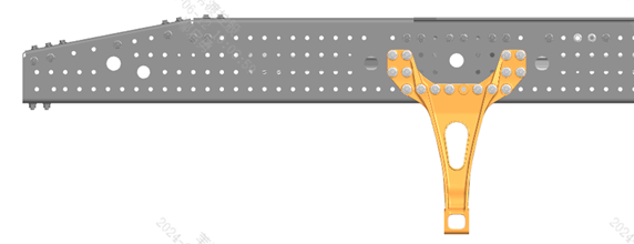
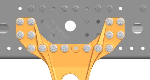
Step 10 Install the torque rod bracket on the left side of the frame at the position shown. Steps 20-30 Tighten with the matching bolts and nuts — one bolt and one nut of these are installed on the high-voltage cable module; be careful not to miss them. Step 40 The High-Voltage Harness Retaining Bracket Assembly IX is installed together with the torque rod bracket in the same step; it is not a separate step.
Parts required
Torque rod bracket ×2; Hex flange bolt (coarse shank) ×8; All-metal hex flange lock nut ×29 (including 1 on the high-voltage cable module); Hex flange bolt ×13 (including 1 on the high-voltage cable module); High-voltage harness retaining bracket assembly IX ×1 (installed together)
Tools / fixtures
Torque wrench
✓ Quality inspection points
Tightening torque: 700±50 N·m (if in doubt, confirm with the process engineer whether this torque applies to the bracket bolts)
Reference illustrations (click to enlarge)
Differential lock solenoid valve installation
Page 1 Operation steps
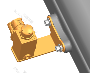
Step 10 Install the differential lock solenoid valve at the position shown. This operation consists of this single step only.
Parts required
Differential lock solenoid valve ×1
Hex flange self-tapping bolt ×2
✓ Quality inspection points
Visual inspection
Reference illustrations (click to enlarge)
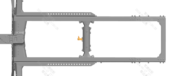
L-shaped bracket (chassis wiring harness)
Page 5 / Over 20 pieces across the front, middle and rear frame sections Operation steps
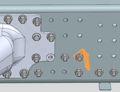
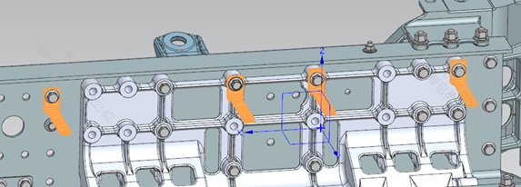
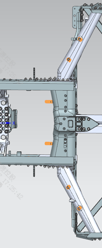
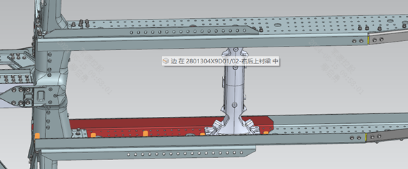
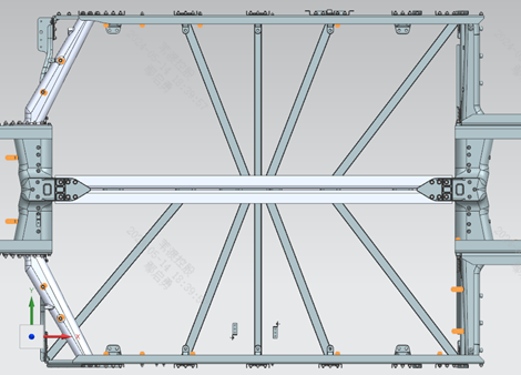
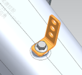
Step 10 Check the incoming condition of the brackets: the surface must be free of burrs, with intact paint and no corrosion. Step 20 Install the water line retaining brackets at positions B/C in the front frame section as shown; install the brackets tilted forward at 45°, with position C installed symmetrically to position B. Step 30 Install the water line bracket at the "Position A (enlarged)" location in the front section. Step 40 Tighten the fasteners to ensure the brackets are installed square and true, not tilted. Step 50 Install the flanged bracket on the underside of the frame rail in the front frame section, and install the wiring harness brackets on the right front crossmember and front-middle crossmember. Step 60 Tighten the fasteners; the fasteners sharing bolt holes with the subframe are to be tightened to 180 N·m. Step 70 Install the L-shaped brackets in the front frame section, 6 pieces in total. Step 80 Tighten the fasteners to ensure square and true installation. Step 90 Install the L-shaped brackets on both sides of the middle frame section, 11 pieces in total. Step 100 Tighten the fasteners. Step 110 Install 3 L-shaped brackets and 1 line bundle retaining bracket on the left frame rail in the rear frame section. Step 120 Tighten the fasteners to ensure square and true installation.
Parts required
Water line retaining bracket ×6; Flanged bracket ×2; Wiring harness bracket ×2; L-shaped bracket × approx. 23 pieces in total, distributed across the front/middle/rear sections; Line bundle retaining bracket ×1; Bolts/nuts × matched to the quantity per section
Tools / fixtures
Torque wrench
✓ Quality inspection points
Fasteners sharing bolt holes with the subframe: 180±15 N·m; Visual inspection
Reference illustrations (click to enlarge)
Brake line installation
Page 9 / Complex line routing with many illustrations Operation steps
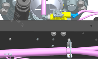
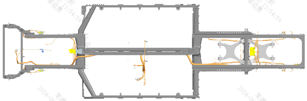
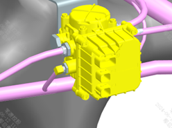
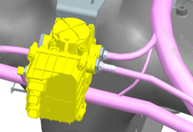
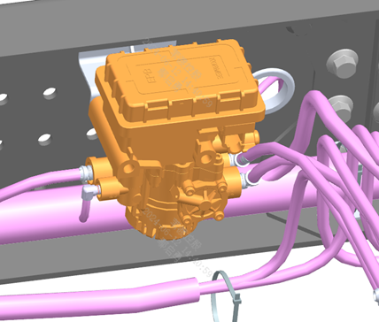
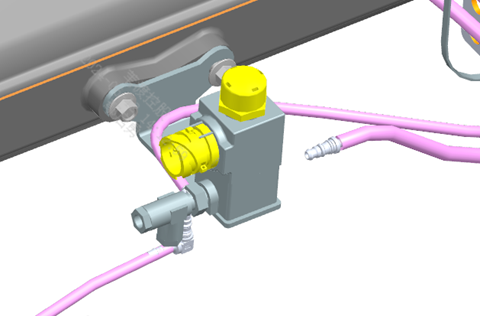
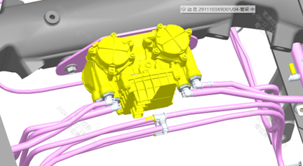
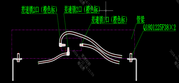
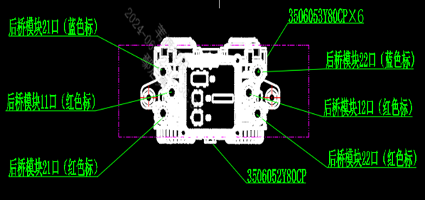
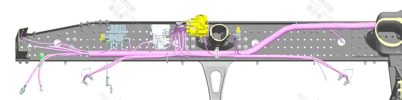
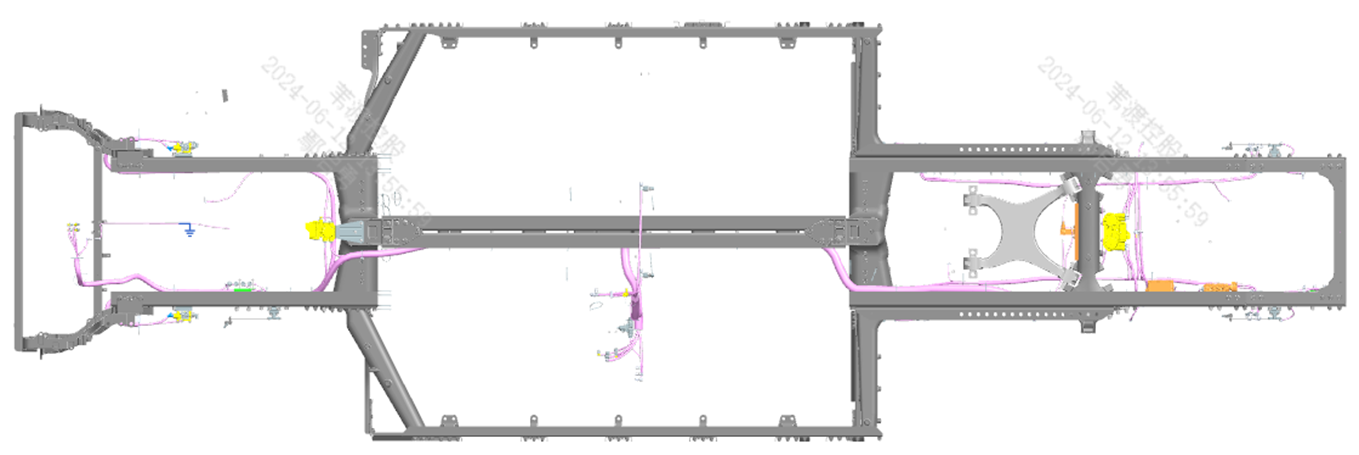
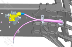
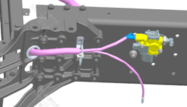
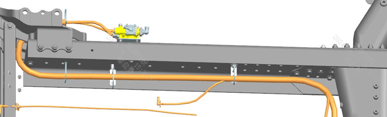
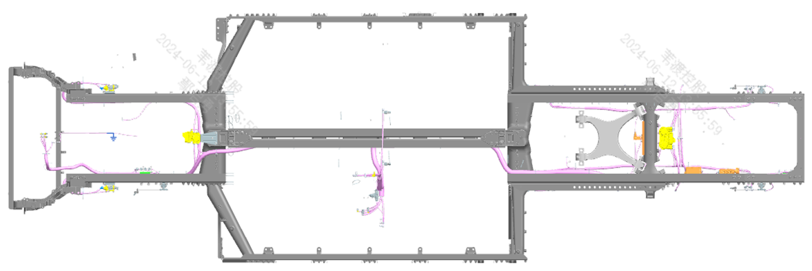
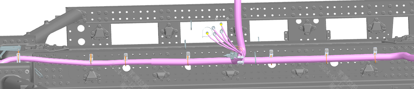
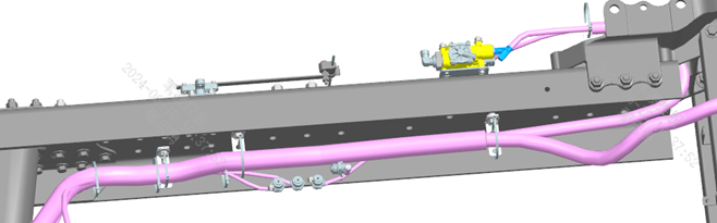
Step 10 Lay out the brake line bundle assembly as shown in Fig. 1; after aligning the 2 positioning marks on the bundle, use flat-head cable ties to temporarily fix the bundle to the adjacent bracket. Step 20 Route the brake line bundle assembly (main line) neatly according to Fig. 2 and temporarily fix it first (do not cinch the cable ties tight yet). Step 30 Route and temporarily fix the brake line bundle assembly (the small sub-assembly above the rear tandem axle) per Fig. 2; distinguish the left and right lines by the end markings "21" (left) and "22" (right) — do not install them reversed. Step 40 Connect and fix the lines to the left/right ABS solenoid valves and the single-channel valve per Fig. 3. Pneumatic line quick-connect fitting installation method: remove the protective cap from the nylon tube → push the quick-connect fitting into the hole in the nut seat → press the fitting by hand until the retaining clip snaps into the groove at the front of the fitting → pull back slightly to check that the clip is fully seated and the fitting is not tilted → when the red O-ring is no longer visible, the fitting is correctly installed. Step 50 Connect and fix the lines of the dual-channel module per Fig. 4. Step 60 Connect and fix the lines of the differential lock solenoid valve block per Fig. 5. Step 70 Connect and fix the lines of the parking brake solenoid valve block per Fig. 6. Step 80 Fix the brake lines per Figs. 7-9, ensuring the lines are smooth, free of sagging and kinks; keep a minimum clearance of no less than 20 mm between the lines and moving parts; the spacing between fixing points must not exceed 300 mm.
Parts required
Brake line bundle assembly ×1
Flat-head cable tie 1 ×45
✓ Quality inspection points
Line fixing spacing: not more than 300 mm; Minimum clearance to moving parts: not less than 20 mm; Quick-connect fittings must be checked for fully seated retaining clips and no tilting; Visual inspection
Reference illustrations (click to enlarge)
A/C line bracket
Page 1 Operation steps
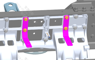
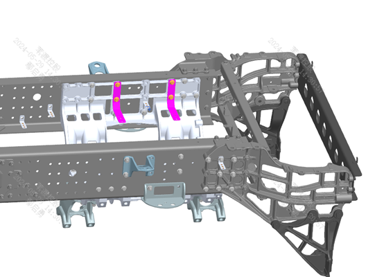
Step 10 Install the A/C line bracket as shown — only the front bracket is installed at this workstation. Step 20 The rear bracket is installed together with the front shock absorber bracket; it is not completed separately at this workstation. Step 30 Tighten the fasteners, ensuring the bracket is installed squarely and not tilted; the fasteners sharing bolt holes with the subframe are to be tightened to 180 N·m.
Parts required
Line retaining bracket 1 ×1
Hex flange bolt (coarse shank) ×2
All-metal hex flange lock nut ×2
Tools / fixtures
Torque wrench
✓ Quality inspection points
Tightening torque: 180±15 N·m
Reference illustrations (click to enlarge)
Front shock absorber upper bracket installation
Page 1 Operation steps
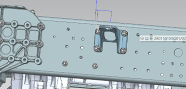
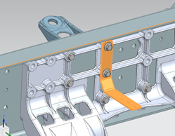
Step 10 Install the front shock absorber upper mounting bracket onto the frame at the position shown; distinguish the left and right brackets by the markings on the parts and do not install them reversed. Step 20 Fix the A/C line bracket 1 together with the left front shock absorber upper mounting bracket. Step 30 Fix the air horn bracket together with the right front shock absorber upper mounting bracket. Step 40 Tighten the fasteners to 180 N·m.
Parts required
Left front shock absorber upper mounting bracket ×1
Right front shock absorber upper mounting bracket ×1
A/C line retaining bracket 1 ×1
Air horn bracket ×1
Hex flange bolt (coarse shank) ×8
All-metal hex flange lock nut ×6
Tools / fixtures
Torque wrench
✓ Quality inspection points
Tightening torque: 180±15 N·m (recheck on first unit/daily)
Reference illustrations (click to enlarge)
Subframe lower connecting bracket installation
Page 2 Operation steps
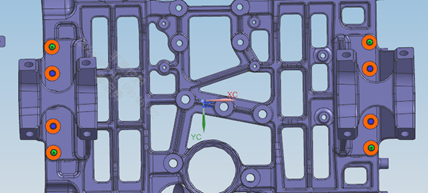
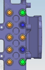
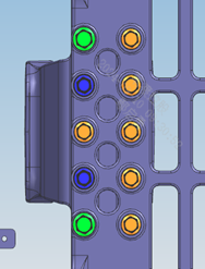
Step 10 Install the subframe lower connecting front/rear brackets onto the underside of the subframe at the positions shown. Step 20 First position and connect the brackets with 4 locating bolts (marked green), then install the remaining connecting bolts; connect and tighten with the fasteners at 8 points in total. Step 30 Tighten the fasteners to 180 N·m.
Parts required
Subframe lower connecting front bracket ×1; Subframe lower connecting rear bracket ×1; Subframe locating bolt 14×78 ×4; Hex flange bolt (coarse shank) ×12; All-metal hex flange lock nut ×8; Hex flange bolt ×4
✓ Quality inspection points
Tightening torque: 180±15 N·m; Visual inspection
Reference illustrations (click to enlarge)
Lower guard mounting bracket
Page 1 Operation steps
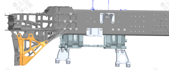
Step 10 Install the "lower guard left mounting bracket" at the position shown; make sure the heavy-duty spring washers are installed in the correct positions. Step 20 Install the "lower guard right mounting bracket" symmetrically to the left side. Step 30 Tighten to 570 N·m.
Parts required
Lower guard left mounting bracket ×1
Lower guard right mounting bracket ×1
Hex head bolt ×6
Heavy-duty spring washer ×6
Tools / fixtures
Torque wrench
✓ Quality inspection points
Tightening torque: 570±30 N·m
Reference illustrations (click to enlarge)
This page is compiled from process cards ZD102-1010 ~ ZD102-1120 (Anhui Windrose Holdings Co., Ltd.) and is for workshop visual training display only; official production shall follow the controlled process documents.