Install high-voltage cablesInstall electric and air hornsInstall closing cross memberInstall air-spring swing arms and linksInstall thermal management device water pipesFill steering fluidInstall battery bracketInstall cab grounding harnessInstall upper wheel-arch mounting brackets
High-voltage Cables, Horns, Air-spring Swing Arms, Water Pipes Pre-assembly Station · Illustrated version of 9 operations | Compiled from the original process card for training and display
Install high-voltage cables
Page 10 / Battery 1-6 positive/negative cables + motor high-voltage cables | Operation steps
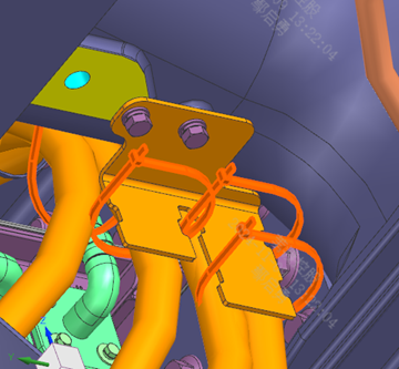
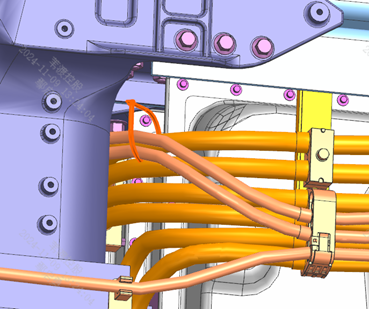
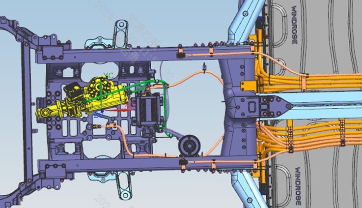
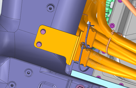
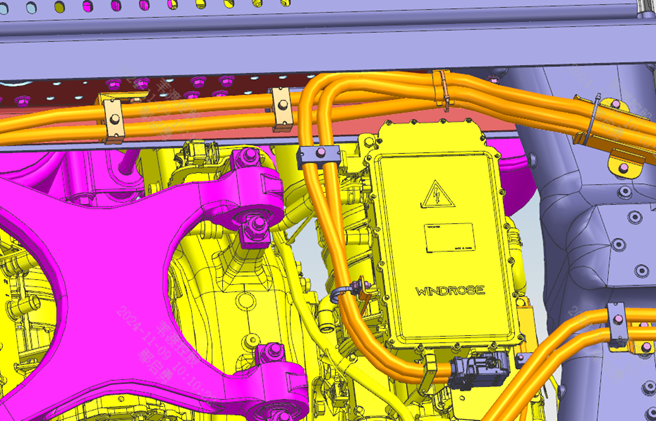
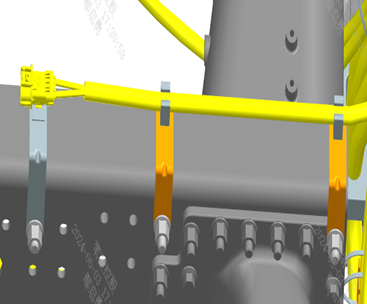
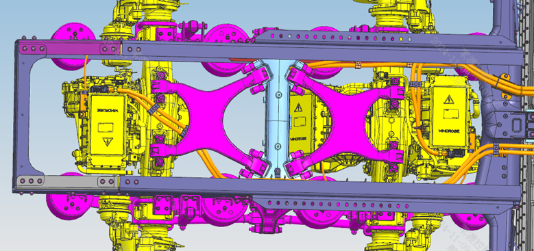
Step 10: Secure the 7 types of high-voltage cables listed in the table to the brackets with pipe clamps as shown; cable locating datum: the rear edge of the white locating mark must align with the front face of the pipe clamp (the APTC power distribution cable assembly III uses the front end of the cable as the locating datum). Step 20: Mount the high-voltage harness fixing pipe clamps onto the brackets; the clamp slot must be parallel to the frame side rail. Step 30: Fix the front-end terminal clips of the cables to the brackets and secure them with pipe clamps, ensuring the cables are straight after installation. Step 40: Fix each cable into the pipe clamps as shown in the cross-section diagram, ensuring the cables between the clamps are straight and not intertwined. Step 50: Temporarily fix the cables before and after the cable fixing points to the top of the frame to avoid interference when installing the battery packs. Step 55: Install and connect the high-voltage cables for the oil pump and the A/C compressor as shown. Step 60: Secure the 2 motor high-voltage cables to the bracket with assembly pipe clamps; locating datum: the rear edge of the white locating mark must align with the rear face of the pipe clamp. Steps 70-80: Secure each cable as shown in the cross-section diagram, keeping the cables straight and not intertwined; overlap the 4 cables as shown and secure with cable ties. Step 95: Install the high-voltage cable for the rear axle (or middle axle) motor as shown, fixing it with the bridge's own cable clips near the connectors. Step 96: Fix the middle axle (or rear axle) grounding harness to the frame as shown; scrape the paint off the grounding mounting surfaces first, then fully cover with petroleum jelly after installation.
Parts required
Battery 1-6 positive/negative cable assembly ×1 each; APTC power distribution cable assembly I/III ×1 each; Oil pump three-phase cable assembly ×1; Compressor power distribution cable assembly I ×1; Motor power cable assembly I/IV ×1 each; High-voltage harness fixing pipe clamp (II/III/IV/VII/VIII) × matching each section; High-voltage harness fixing bracket assembly (A3/B1/B2) ×1 each; Flat-head cable tie 1 / round-head cable tie × as required; Conical lock washer × several
✓ Quality inspection points
Visual inspection: grounding surfaces must have the paint scraped off and be covered with petroleum jelly
Reference illustrations (click to enlarge)
Install electric and air horns
Page 1 | Operation steps
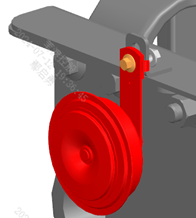
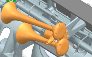
Step 10: Install the air horn onto the fixing bracket as shown. Step 20: Install the high-tone and low-tone electric horns on the closing cross member as shown. Step 30: Note: do not mix up the high-tone and low-tone electric horns.
Parts required
Air horn ×1
Electric horn assembly — high tone ×1
Electric horn assembly — low tone ×1
Hex flange bolt (thick shank) ×4
Hex flange nut ×2
✓ Quality inspection points
Visual inspection: the high-tone and low-tone electric horns must not be mixed up
Reference illustrations (click to enlarge)
Install closing cross member
Page 1 | Operation steps
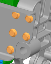
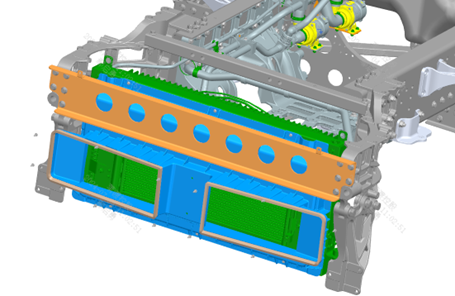
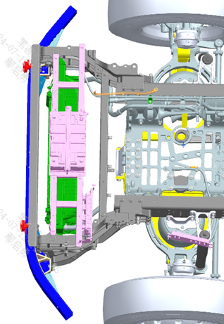
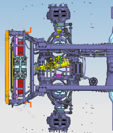
Step 10: Install the closing cross member at the front end of the frame as shown. Step 20: Connect and tighten the left end of the closing cross member to the left front connecting beam as shown; install the right end symmetrically to the left.
Parts required
Closing cross member ×1
Hex flange bolt (thick shank) ×10
✓ Quality inspection points
Visual inspection
Reference illustrations (click to enlarge)
Install air-spring swing arms and links
Page 1 | Operation steps
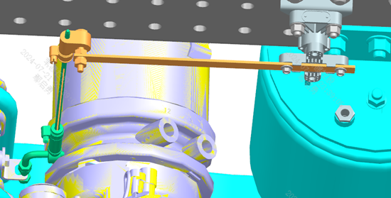
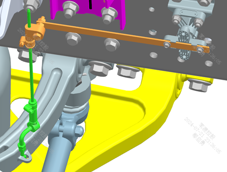
Step 10: Install the swing arm and link on the left side of the front axle (see figure). Step 20: Install the swing arm and link on the left side of the rear axle (see figure). Step 30: Install the swing arm on the right side of the rear axle symmetrically to the left side; swing arm 1 is installed at the position symmetrical to swing arm 2. Step 40: Note the relative inboard/outboard positions of the swing arms and links (they differ between front and rear — do not mix them up). Step 50: The lower end of the link must protrude beyond the axle-end fixing nut by about 4-5 threads; the swing arm initial position should be basically horizontal and parallel to the frame. Step 60: Install the connecting screw rod and support strut, adjusting to the reference heights marked in the figure on the left. Step 70: Torque requirements: ① fixing bolt of the swing arm assembly to the height sensor shaft — max 10 N·m; ② height sensor body fixing bolt — max 15 N·m; ③ bolt connecting the L-type link to the axle — max 23 N·m; ④ locking screw of the rubber sleeve locking clamp — max 2 N·m; ⑤ nut seat and straight-through joint tightening torque — 10-16 N·m.
Parts required
Swing arm 1 ×2
Swing arm 2 ×1
Connecting link ×3
Hex flange bolt with serrated bearing face ×6
Tools / fixtures
Torque wrench
✓ Quality inspection points
The torque at each connection point must not exceed its corresponding limit (see Step 70)
Reference illustrations (click to enlarge)
Install thermal management device water pipes
Page 5 / Each side has two parts: bracket + water pipe | Operation steps
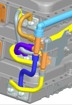
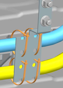
Step 10 (left bracket): Install the left-side water pipe bracket as shown. Step 20 (right bracket): Install the right-side water pipe bracket as shown. Step 30 (left pipe): Install the left-side water pipe as shown (the frame is hidden in the view to make the routing clear). Step 40 (right pipe): Install the right-side water pipe as shown (the frame is hidden in the view).
Parts required
Battery pack line fixing bracket ×4; Left/right battery pack joint fixing bracket ×1 each; Battery line four-way joint ×4; Left 1-3 / right 1-3 battery pack inlet/outlet nylon pipe ×1 each; Flat-head cable tie 1 ×16
Tools / fixtures
Torque wrench
✓ Quality inspection points
Tightening torque: 23±3 N·m
Reference illustrations (click to enlarge)
Fill steering fluid
Page 1 | Operation steps
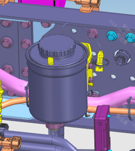
Step 10: The fill port location is as shown. Step 20: Fill steering fluid until the reservoir is full to just below overflowing. Step 30: After the vehicle's high-voltage system is powered on, turn the steering wheel in place to start the power steering pump, check and top up the steering fluid; after turning the steering wheel to its full left and right stops for 4-5 cycles, check the level gauge — the level should be between the MAX and MIN marks. Step 40: Check the fluid level again after the vehicle dynamic road test; requirements are the same as above.
Parts required
Transmission hydraulic fluid ×4
L (reference quantity)
✓ Quality inspection points
The fluid level must be between the MAX and MIN marks
Reference illustrations (click to enlarge)
Install battery bracket
Page 1 | Operation steps
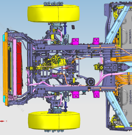
Step 10: Install the battery assembly bracket onto the front section of the frame as shown. Step 20: Install the battery spacer plate onto the battery assembly bracket as shown.
Parts required
Battery assembly bracket ×1
Battery spacer plate ×1
Hex flange bolt (thick shank) ×10
All-metal hex flange lock nut ×4
✓ Quality inspection points
Visual inspection
Reference illustrations (click to enlarge)
Install cab grounding harness
Page 1 | Operation steps
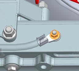
Step 10: Connect the cab grounding harness to the chassis frame as shown. Step 20: Scrape off the paint on the lap surfaces between the frame and the serrated lock washers, and apply petroleum jelly for protection after installation. Note: the lap surfaces must have the paint scraped off, and the serrated washers must be installed in the correct position — do not install them reversed.
Parts required
Cab grounding harness ×1
Hex flange nut ×1
Internal-external serrated lock washer ×1
Hex flange bolt (thick shank) ×1
✓ Quality inspection points
The lap surfaces must have the paint scraped off and be coated with petroleum jelly for protection
Reference illustrations (click to enlarge)
Install upper wheel-arch mounting brackets
Page 1 | Operation steps
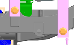
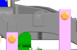
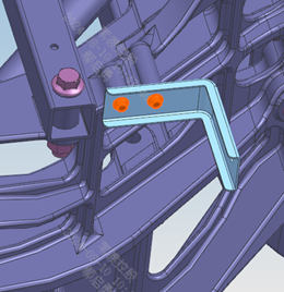
Step 10: Install the upper wheel-arch mounting bracket on the left side of the frame as shown. Step 20: Install the right-side bracket symmetrically to the left.
Parts required
Upper wheel-arch mounting bracket ×2
Hex flange bolt (thick shank) ×4
✓ Quality inspection points
Visual inspection
Reference illustrations (click to enlarge)
This page is compiled from the ZD109-1010 to ZD109-1090 process cards (Anhui Windrose Holdings Co., Ltd.) and is for workshop visual training only; official production shall follow the controlled process documents.