Install rear-view cameraInstall front bulkhead junction boxes and bracketsInstall batteriesInstall front millimeter-wave radar bracketInstall bumperInstall vehicle control unit (powertrain domain controller)Install light barInstall rear work lampInstall chassis intelligent junction boxInstall front compartment trim panelInstall front compartment sealing stripsInstall air compressor air filterHigh-voltage cable — PDU connection
Front-compartment Electrical, Front Face / Front Bumper Pre-assembly Station · Illustrated version of 13 operations | Compiled from the original process card for training and display
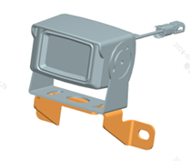
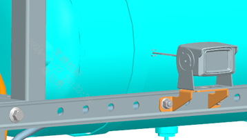
Install rear-view camera
Page 1 | Operation steps
Step 10: Install the rear-view camera onto the bracket as shown (use the fasteners supplied with the camera). Note: the reverse camera is not installed — it travels with the vehicle.
Parts required
Rear-view camera ×1
✓ Quality inspection points
Visual inspection
Reference illustrations (click to enlarge)
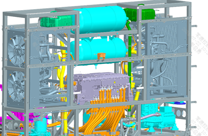
Install front bulkhead junction boxes and brackets
Page 2 | Operation steps
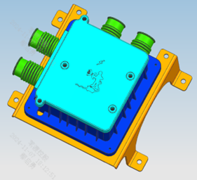
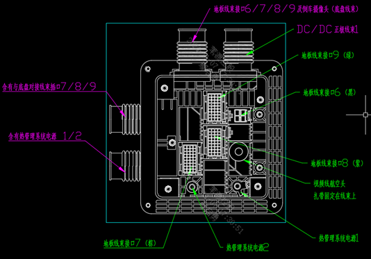
Step 10: Pre-assemble the front bulkhead junction boxes first: fix the left and right front bulkhead junction boxes to the brackets with 4 nuts; be sure to distinguish the left and right junction boxes and the relative positions of the junction boxes and brackets. Step 20: Turn the right junction box assembly 180° so the bottom faces up; per the wiring diagram, plug in the chassis harness connectors to the connectors of the matching color on the junction box, snap the sealing grommets into the corresponding wire holes, and tighten the lower cover plate with 4 M6×20 bolts; then turn the junction box back upright and fix it to the chassis with 4 M8×20 bolts. Step 30: Plug in the floor harness connectors to the matching-color connectors on the junction box as shown, snap the sealing grommets into the corresponding wire holes, and tighten the upper cover plate with 5 M6×20 bolts. Step 40: Install and wire the left junction box by referring to the right junction box; the terminals of the DC/DC positive cable harness 1 and thermal management system power 1/2 are tightened with M8 nuts. Step 50: Fix the harness with cable ties as shown; note that it must not interfere with or catch on the sharp edges of metal parts.
Parts required
Front bulkhead junction box bracket ×2
Left front bulkhead junction box ×1
Right front bulkhead junction box ×1
Hex flange nut ×8
Hex flange bolt (thick shank) ×26
All-metal hex flange lock nut ×4
Flat-head cable tie 1 × as required
✓ Quality inspection points
Connector colors must match — do not plug them in wrong; The harness must be fixed clear of sharp metal edges
Reference illustrations (click to enlarge)
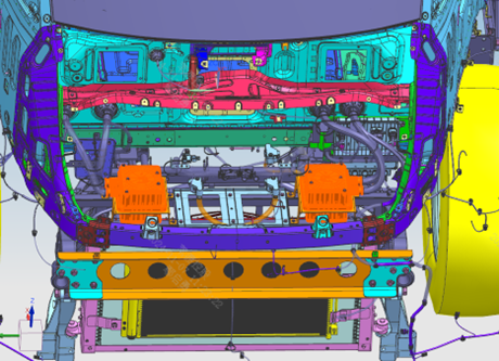
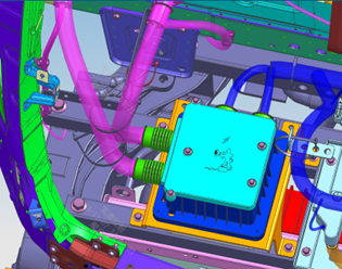
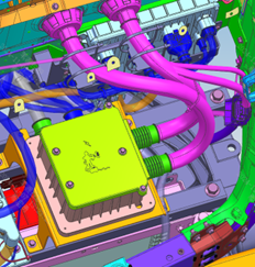
Install batteries
Page 1 | Operation steps
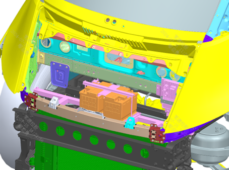
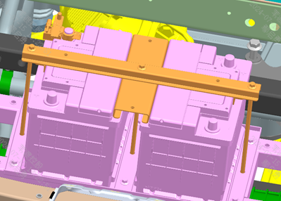
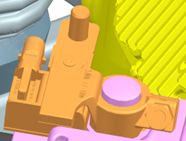
Step 10: Place the batteries on the battery spacer plate, positioned squarely. Step 20: Position battery hold-down plates 2 and 3 as shown, and connect and tighten them with the battery tie rods. Step 30: Press the intelligent battery sensor onto the battery negative terminal post at the position shown and tighten, tightening torque 5 N·m. Step 40: Note: for terminal posts that are not connected, the protective caps must be kept in place.
Parts required
Auxiliary battery ×2
Battery hold-down plate 2 ×1
Battery hold-down plate 3 ×1
Battery tie rod ×3
Intelligent battery sensor ×1
Tools / fixtures
Torque wrench
✓ Quality inspection points
Sensor tightening torque: 5 N·m; Unconnected terminal posts must keep their protective caps
Reference illustrations (click to enlarge)
Install front millimeter-wave radar bracket
Page 1 | Operation steps
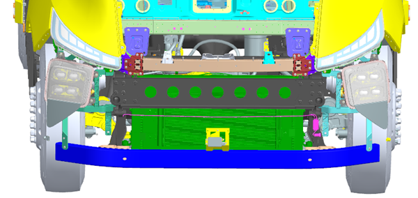
Step 10: Install the front millimeter-wave radar assembly onto the front lower guard as shown.
Parts required
Millimeter-wave radar bracket ×1
Hex flange bolt (thick shank) ×2
Tools / fixtures
Torque wrench
✓ Quality inspection points
Tightening torque: 23±3 N·m
Reference illustrations (click to enlarge)
Install bumper
Page 3 / Frame + assembly + radar accessories | Operation steps
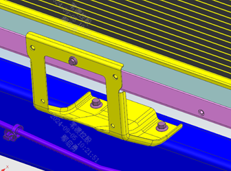
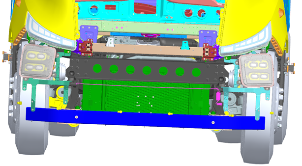
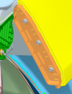
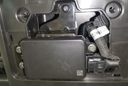
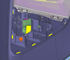
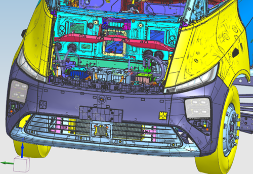
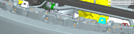
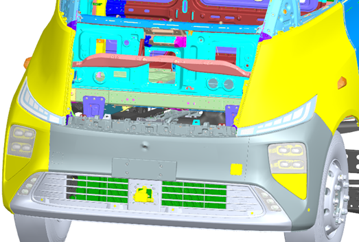
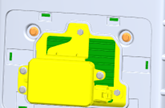
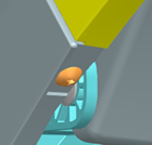
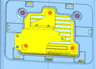
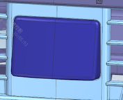
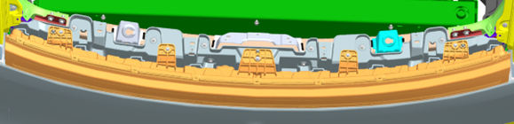
Step 10: First install the left bumper mounting frame as shown. Step 20: Locate and center the frame, securing it with 3 bolts. Step 30 (frame): Install the right bumper mounting frame symmetrically to the left side. Step 30 (assembly): Confirm that the front millimeter-wave radar bracket has been installed; install the bumper assembly along the positive X direction, inserting the center locating pin. Step 40: Tighten the bumper assembly at position A to the upper radiator-support cross member of the body with 10 bolts. Step 50: Using the natural flex of the bumper assembly, snap it into place in sequence: 2 integral clips engage the left front combination lamp, 4 integral clips engage the left bumper mounting frame, 2 integral clips engage the right front combination lamp, and 4 integral clips engage the right bumper mounting frame. Step 60: Tighten the bumper assembly at position F to the front lower guard with 7 bolts. Step 70: Tighten the bumper assembly at positions GH to the left/right headlamp brackets with 2 bolts. Step 80: Tighten the bumper assembly at position I to the 4D millimeter-wave radar bracket with 2 bolts. Step 90: Snap the front millimeter-wave radar cover into the center of the front bumper. Step 100 (radar): Confirm that the front millimeter-wave radar has been installed; install the front millimeter-wave radar adapter bracket, forward millimeter-wave radar, cover and left/right corner radar cover plates, connect the radar harness and fix it to the front bumper as shown.
Parts required
Left/right bumper mounting frame ×1 each; Bumper assembly ×1; Front millimeter-wave radar adapter bracket ×1; Forward millimeter-wave radar ×1; Front millimeter-wave radar cover ×1; Left/right corner radar cover plate ×1 each; Hex flange bolt (thick shank) × matching each step; Cross-recessed truss-head self-tapping screw ×2
✓ Quality inspection points
Tightening torque: 23±3 N·m; The integral clip engagement points must be verified one by one to avoid missed clips
Reference illustrations (click to enlarge)

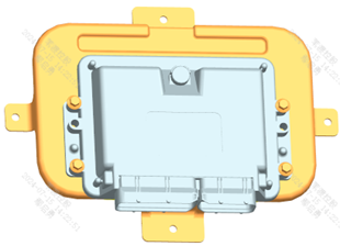
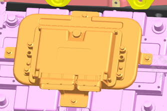
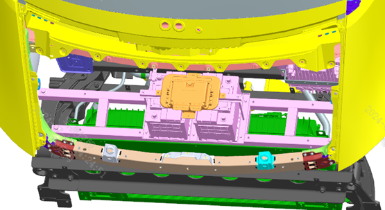
Install vehicle control unit (powertrain domain controller)
Page 1 | Operation steps
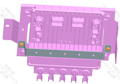
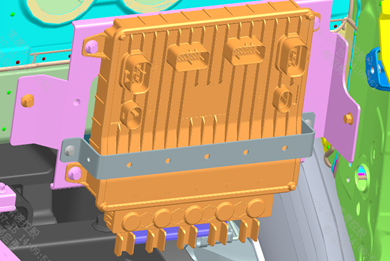
Step 10: Assemble the powertrain domain controller and bracket into an assembly first. Step 20: Install the powertrain domain controller assembly into the front compartment, connect and tighten it; note the length of the fasteners — if too long they will damage the batteries.
Parts required
Powertrain domain controller assembly ×1
Powertrain domain controller bracket ×1
Hex flange bolt (thick shank) ×8
✓ Quality inspection points
Tightening torque: 23±3 N·m; The fasteners must not be too long, to avoid damaging the batteries
Reference illustrations (click to enlarge)
Install light bar
Page 1 | Operation steps
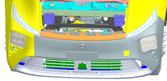
Step 10: Insert the light bar's loose wires into hole 1, then install the light bar. Step 20: Place the light bar onto the middle bumper upper body assembly, aligning the locating holes at the 3 locating points with the left headlamp bracket. Step 30: Align the 5 clips on the light bar with the openings in the middle bumper upper body assembly and press in along the Z direction. Step 40: Secure the light bar to the bumper upper body frame assembly with M6 bolts. Step 50: Mate and secure the light bar with the floor harness connector.
Parts required
Light bar ×1
Hex flange bolt (thick shank) ×5
✓ Quality inspection points
Tightening torque: 23±3 N·m
Reference illustrations (click to enlarge)
Install rear work lamp
Page 1 | Operation steps
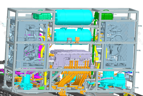
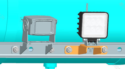
Step 10: Install the rear work lamp onto the bracket as shown (use the fasteners supplied with the work lamp). Step 20: Connect and secure the harness.
Parts required
Rear work lamp ×1
Tools / fixtures
Pointer-type torque wrench
✓ Quality inspection points
Tightening torque: 700±50 N·m
Reference illustrations (click to enlarge)
Install chassis intelligent junction box
Page 2 | Operation steps
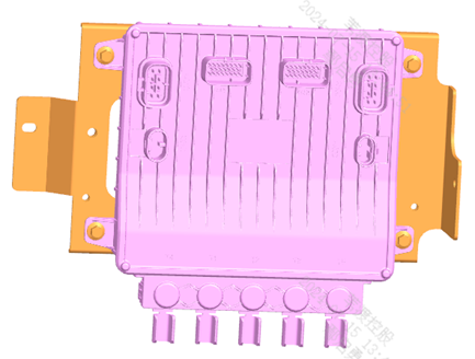
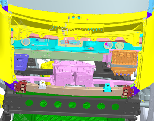
Step 10: Place the chassis intelligent junction box onto the chassis intelligent junction box bracket and secure the junction box to the bracket with bolts. Step 20: Fix the chassis intelligent junction box bracket 2 onto the chassis intelligent junction box bracket. Step 30: Install the chassis intelligent junction box assembly into the front compartment, connect and tighten it.
Parts required
Intelligent junction box — chassis ×1
Chassis intelligent junction box bracket ×1
Chassis intelligent junction box bracket 2 ×1
Hex flange bolt (thick shank) ×6
Hex flange bolt ×2
✓ Quality inspection points
Tightening torque: 23±3 N·m
Reference illustrations (click to enlarge)
Install front compartment trim panel
Page 1 | Operation steps
Step 10: First insert the 4 locating pins of the front compartment trim panel body into the locating holes of the bumper assembly. Step 20: Tighten the 4 self-tapping screws in the middle that fix it to the bumper. Step 30: Then tighten the 2 self-tapping screws fixing it to the fenders on both sides. Step 40: After assembly, check for any missing or loose parts.
Parts required
Front compartment trim panel body ×1
Cross-recessed truss-head self-tapping screw ×6
Tools / fixtures
Pointer-type torque wrench
✓ Quality inspection points
Tightening torque: 700±50 N·m; Check for any missing or loose parts
Reference illustrations (click to enlarge)

Install front compartment sealing strips
Page 1 | Operation steps
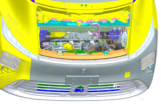
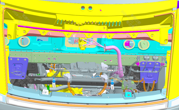
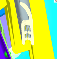
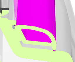
Step 10: Install the 3 sealing strips in the front compartment as shown. Step 20: Snap them fully into place, straight and without twisting; clean the bonding surfaces before bonding to ensure they are free of oil and dust.
Parts required
Front compartment front sealing strip assembly ×1
Left/right front compartment sealing strip ×2
✓ Quality inspection points
The sealing strips must be straight and without twisting; the bonding surfaces must be clean and free of oil
Reference illustrations (click to enlarge)
Install air compressor air filter
Page 1 | Operation steps
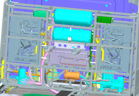
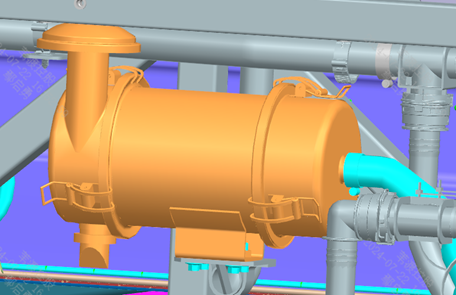
Step 10: Install the air filter assembly onto the corresponding bracket of the integrated frame as shown. Step 20: Connect the intake hose to the air filter (the pipe clamp is supplied with the hose).
Parts required
Air filter assembly ×1
Hex flange bolt with serrated bearing face ×4
Tools / fixtures
Pointer-type torque wrench
✓ Quality inspection points
Tightening torque: 700±50 N·m
Reference illustrations (click to enlarge)
High-voltage cable — PDU connection
Page 3 / Actual steps are on page 1 | Operation steps
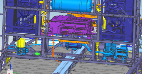
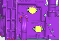
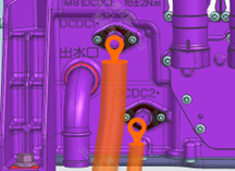
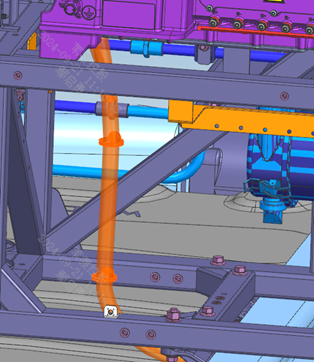
Step 10: Prepare the installation of the DC/DC positive cable harness 1. Step 20: Route the harness below the integrated frame to the connection position on the left side of the PDU as shown in Figure 1; first remove the dust cover at the PDU connection terminals, then mount the harness terminals onto the PDU using the bolts supplied with the PDU. Step 30: Fix the harness to the integrated frame as shown in Figure 1, at 2 fixing points. Step 40: Refit the dust cover to its original position. Step 50: Connect and install the cables of the oil pump, compressor and APTC as shown in Figure 2. Step 60: First install the harness fixing bracket assemblies 26/27 as shown in Figure 3, then secure the cables to the bracket with pipe clamps. Step 70: Remove the PDU sealing end cover, then unscrew the supplied fixing bolts. Step 80: Per the terminal markings, connect and fix the terminals to the PDU with the PDU-supplied bolts, tightening torque 30 N·m. Step 90: Clip the cables into the pipe clamps at the corresponding positions and reinstall the PDU sealing end cover.
Parts required
Flat-head cable tie 1 ×2; Pine-tree cable tie ×4; Flat-head cable tie 2 ×3; High-voltage harness fixing bracket assembly T27/T26 ×1 each; Hex bolt with spring and flat washer assembly ×4; High-voltage harness fixing pipe clamp VI ×4; Hex flange bolt ×4
Tools / fixtures
Torque wrench
✓ Quality inspection points
PDU terminal tightening torque: 30±3 N·m; The dust cover / sealing end cover must be removed and refitted in order and restored to position
Reference illustrations (click to enlarge)
This page is compiled from the ZD111-1010 to ZD111-1120 process cards (Anhui Windrose Holdings Co., Ltd.) and is for workshop visual training only; official production shall follow the controlled process documents.