Rear wheel arch / steering system sub-assembly workstation · 6 operations, illustrated edition | Compiled from the original process cards for training and display-board use
Rear wheel arch / steering system sub-assembly workstation · 6 operations, illustrated edition | Compiled from the original process cards for training and display-board use
Yaw rate sensor installation
Page 1 Operation steps
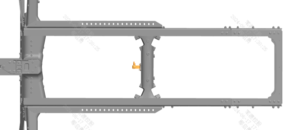
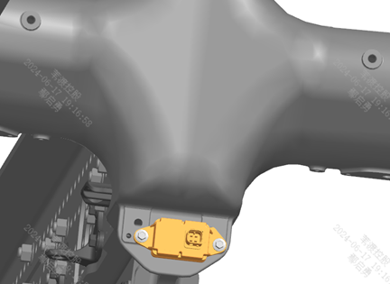
Stap 10 Install the yaw rate sensor assembly at the position shown. Step Tightening Tighten the fixing bolts with a torque wrench.
Parts required
Yaw rate sensor assembly ×1
Hex flange bolt with toothed bearing face ×2
Tools / fixtures
Torque wrench
✓ Quality inspection points
Tightening torque: 700±50 N·m
Reference illustrations (click to enlarge)
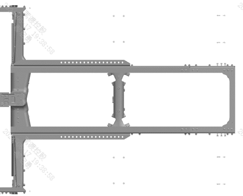
Yaw sensor installation position diagramYaw sensor installation detail
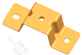
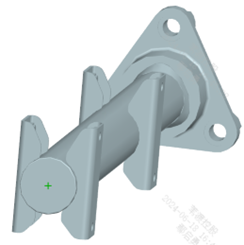
Rear wheel arch front body bracket
Page 1 Operation steps
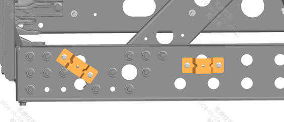
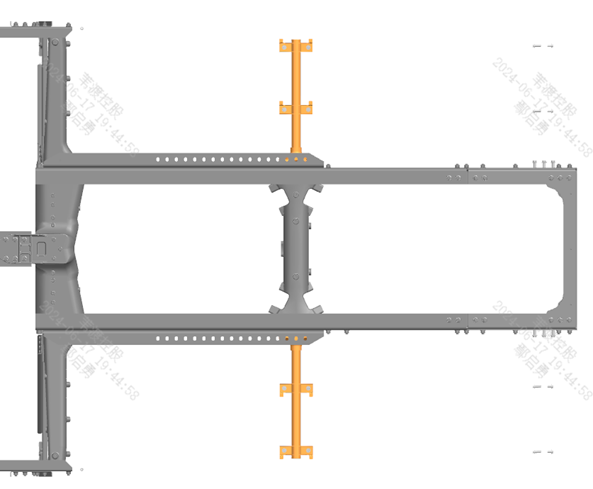
Stap 10 Install the "rear wheel arch front body bracket" on the left side of the frame as shown in the view in direction A in the figure. Stap 20 Install the "rear wheel arch front body bracket" on the right side of the frame symmetrically to the left side.
Parts required
Rear wheel arch front body bracket ×4
Hex flange bolt (coarse shank) ×8
Hex flange nut ×8
Tools / fixtures
Torque wrench
✓ Quality inspection points
Tightening torque: 700±50 N·m
Reference illustrations (click to enlarge)
Rear wheel arch front body bracket installation position(ADirectional view)Bracket installation overall diagramInstallation detail enlarged view
Rear wheel arch center tube beam assembly
Page 1 Operation steps
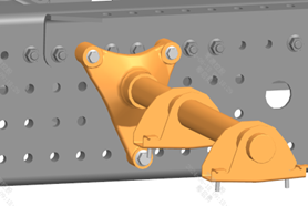
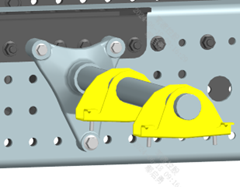
Stap 10 Install the rear wheel arch center tube beam at the position shown. Stap 20 Install symmetrically on the left and right sides and tighten with the matching bolts.
Parts required
Rear wheel arch center tube beam assembly ×2
Hex flange bolt (coarse shank) ×4
Hex flange bolt (coarse shank, long) ×2
Tools / fixtures
Torque wrench
✓ Quality inspection points
Tightening torque: 700±50 N·m
Reference illustrations (click to enlarge)
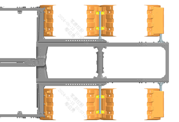
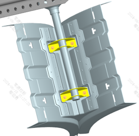
Rear wheel arch center tube beam installation overviewInstallation detail1Installation detail2
Rear wheel arch body installation
Page 4 / Front/middle/rear bodies installed in steps Operation steps
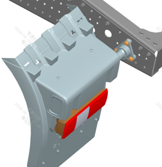
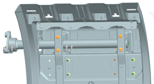
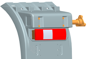
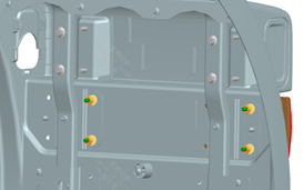
Stap 10 (Front) Left/right front body assembly of the rear wheel arch: before installation, confirm that the rear wheel arch front body bracket has been installed. Stap 20 (Front) Install the left front assembly of the rear wheel arch at the position shown. Stap 30 (Front) The figure shows the installation method for the left front assembly; the right front assembly of the rear wheel arch is installed symmetrically to the left side. Stap 10 (Middle) Left/right middle body installation of the rear wheel arch: before installation, confirm that the rear wheel arch center tube beam has been installed. Stap 20 (Middle) Install the (left) middle body assembly of the rear wheel arch at the position shown. Stap 30 (Middle) Install the right middle body assembly of the rear wheel arch symmetrically to the left side. Stap 10 (Rear) Left/right rear body sub-assembly of the rear wheel arch (shown for the left side): first remove the 4 fixing bolts of the anti-spray mud flap and fold it open to expose the installation positions of the rear combination lamp and the tube beam. Stap 30 (Rear) Install the left rear combination lamp at the position shown in Fig. 2; note that the license plate lamp must face downward; secure the combination lamp with the 4 fixing nuts from the inside of the wheel arch. Stap 40 (Rear) Select the left rear tube beam per Fig. 3, insert the tube beam front fixing bracket into the wheel arch body facing the direction of vehicle travel, align the front and rear mounting holes, and tighten with bolts. Stap 50 (Rear) Re-secure the anti-spray mud flap with 4 screws/bolts. Stap 60 (Rear) The right rear wheel arch rear body sub-assembly is installed symmetrically to the left side. Stap 80 (Assembly) Rear body assembly installation: install the left rear wheel arch rear body assembly at the position shown; the right side is symmetrical to the left side.
Parts required
Left/right front body assembly of rear wheel arch ×1 each; Left/right middle body assembly of rear wheel arch ×1 each; Left/right rear wheel arch tube beam assembly ×1 each; Left/right rear combination lamp ×1 each; Left/right rear wheel arch rear body assembly ×1 each; Hex bolt with spring and flat washer assembly × matched per area; Hex flange bolt/nut × matched per area
Tools / fixtures
Torque wrench
✓ Quality inspection points
Tightening torque: 700±50 N·m; Carefully verify the license plate lamp orientation of the combination lamp and the insertion direction of the tube beam
Reference illustrations (click to enlarge)
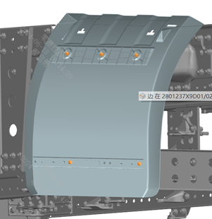
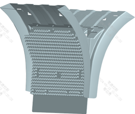
Rear wheel arch left-front assembly installation positionRear wheel arch center body installation positionRear wheel arch rear body installation position(Mud flap removal/installation)Combination lamp installation position and orientationTube beam insertion direction diagramInstallation detail1Installation detail2Installation detail3Rear body assembly final installation position
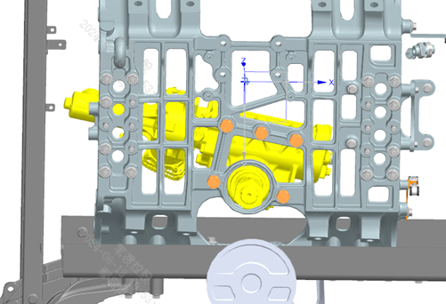
EHPS power steering gear installation
Page 1 Operation steps
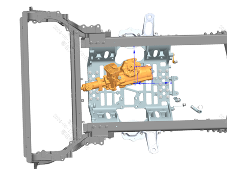
Stap 10 Hoist the EHPS (Electro-Hydraulic Power Steering gear) onto the subframe at the position shown. Stap 20 After aligning the EHPS with the 5 fixing holes on the subframe, hand-start the heavy-duty spring washers and bolts to pre-tighten them, then tighten to the final torque of 550 N·m.
Parts required
EHPS assembly ×1
Heavy-duty spring washer ×5
Hex head bolt ×5
Tools / fixtures
Torque wrench
lifting sling
✓ Quality inspection points
Tightening torque: 550±20 N·m
Reference illustrations (click to enlarge)
EHPSLifting to subframe positionFixing hole alignment detail
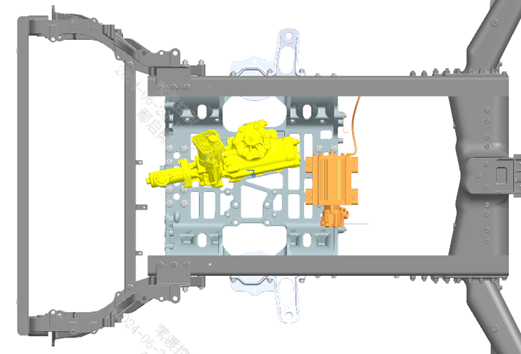
Electric oil pump installation
Page 3 Operation steps
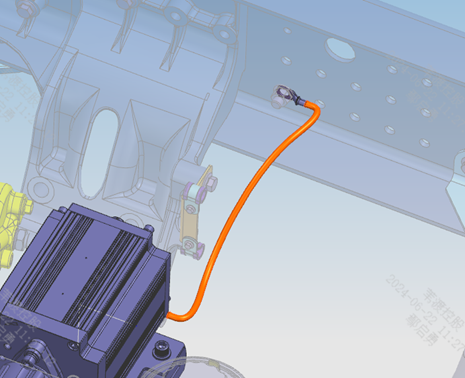
Stap 10 Install the electric oil pump bracket and the steering oil line retaining bracket 1 at the positions shown. Stap 20 When installing steering oil line retaining bracket 1, keep the top edge of the bracket level. Stap 30 Tighten to 65 N·m. Stap 10 (Pump body) Hoist the electric oil pump; align the pump's 4 fixing holes with the holes in the pump fixing bracket and the subframe, then tighten. Stap 20 (Pump body) Tighten to 65 N·m. Stap 10 (Ground) Secure the other end of the ground strap harness supplied with the pump to the frame position shown; before installation, scrape the paint off the contact surfaces between the ground strap terminal and the frame to ensure a good ground.
Parts required
Electric oil pump bracket ×1; Steering oil line retaining bracket 1 ×1; Electric oil pump ×1; Steering oil line retaining bracket 2 ×1; Hex flange bolt (coarse shank) × several; All-metal hex flange lock nut ×1
Tools / fixtures
Torque wrench
lifting sling
✓ Quality inspection points
Tightening torque: 65±5 N·m; The ground contact surface must have the paint scraped off to ensure continuity
Reference illustrations (click to enlarge)
Electric oil pump bracket and oil line bracket installation positionElectric oil pump lifting and ground wire fixing position
This page is compiled from process cards ZD103-1020 ~ ZD103-1070 (Anhui Windrose Holdings Co., Ltd.) and is for workshop visual training display only; official production shall follow the controlled process documents.