Front wheel end and air spring installationBattery pack 2/5 installationBattery pack support (middle layer 3)
Front wheel end / air spring / battery pack sub-assembly workstation · 3 operations, illustrated edition | Compiled from the original process cards for training and display-board use
Front wheel end and air spring installation
Page 4 Operation steps
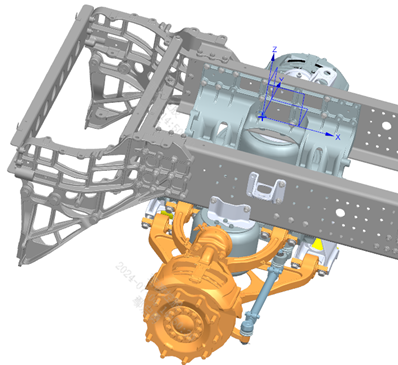
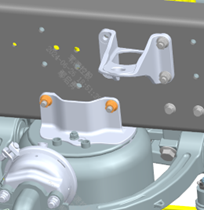
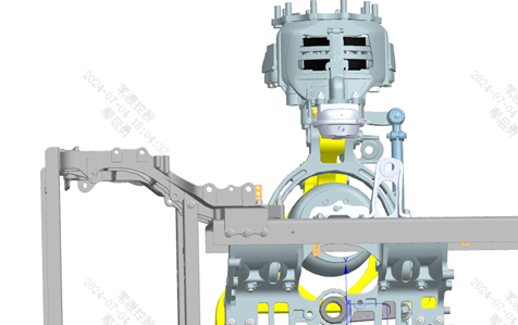
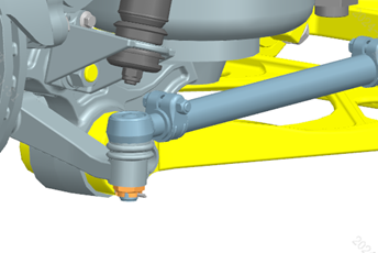
Step 10 First sub-assemble the front air spring. Step 20 Install the spring upper mounting plate onto the front air spring as shown; do not fully tighten the fixing nuts at this point. Step 30 Note the difference between the left and right mounting plates: their fixing holes are symmetrically positioned — do not install them reversed. Step 10 (Wheel end) Installation of the left front wheel end: use the overhead crane to lift the left front wheel end onto the front wheel end lift trolley and locate it per the figure. Step 20 (Wheel end) Use the lift trolley to move the front wheel end to the position below the frame installation point, and pre-place the front air spring assembly in the upper control arm of the front wheel end. Step 30 (Wheel end) Raise the front wheel end and air spring with the trolley, adjust the relative position of the front wheel end and the frame; first align the wheel end upper control arm with the subframe mounting point and install the fasteners without tightening them; move the air spring as needed to avoid interference with tools. Step 40 (Wheel end) Then adjust the trolley height to align the wheel end lower control arm fixing points with the subframe mounting points, install and tighten the fasteners, and simultaneously tighten the upper control arm fasteners. Step 50 (Wheel end) Control arm connecting bolt torque: 568 N·m; apply 1262 thread-locking adhesive to the above fasteners. Step 60 (Wheel end) During assembly, ensure that the air spring upper bracket fits flush against the lower flange surface of the frame rail. Step 60 (Air spring) Square up the air spring, align it with the fixing holes on the front wheel end, connect and tighten to 270 N·m. Step 70 Align the fixing holes of the spring upper mounting plate with the frame, connect and tighten (the right one is installed together with the brake line bracket, see figure). Step 75 Tighten the connecting nuts between the spring upper mounting plate and the spring to 55 N·m. Step 80 Install the left front shock absorber at the position shown; tightening torque: 90 N·m. Step 90 Connect and tighten the steering tie rod to the front wheel end; tightening torque: 345 N·m. Step 100 The connection and installation of the right front wheel end, shock absorber, and tie rod are symmetrical to the left front.
Parts required
Front air spring assembly ×2; Left/right spring upper mounting plate ×1 each; Left/right front wheel end assembly ×1 each; Front shock absorber assembly ×2; Nut M12×1.5 (self-locking) ×2; Nut M20×1.5 (self-locking) ×8; Control arm ball joint fixing bolt ×8; Lower control arm ball joint fixing bolt ×8; Hex slotted thin nut ×2; Cotter pin ×2; L-shaped bracket (brake line device) ×1
Tools / fixtures
Overhead crane
front wheel end lift trolley
torque wrench
✓ Quality inspection points
Control arm connecting bolt torque: 568±28 N·m; Air spring connection torque: 270±25 N·m; Spring mounting plate connecting nut torque: 55±5 N·m; Front shock absorber torque: 90 N·m; Tie rod torque: 345±15 N·m; Air spring upper bracket fits flush against the frame rail lower flange (visual)
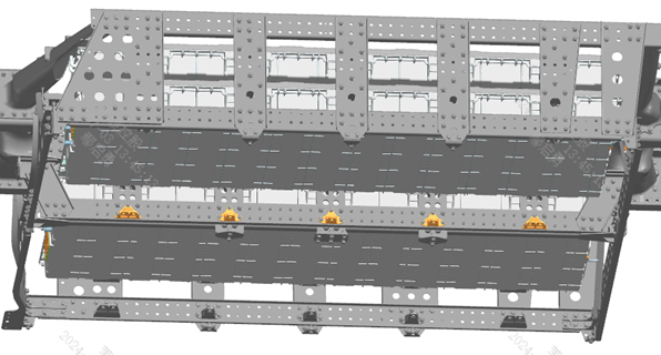
Reference illustrations (click to enlarge)
Battery pack 2/5 installation
Page 2 / Same installation method as battery pack 1 Operation steps
Step 10 Installation of battery pack 2: hoisting preparation. Step 20 Battery pack assembly 2 is installed directly below battery pack assembly 1, shifted down 190 mm; the installation structure and method are the same as for battery pack assembly 1 (refer to the hoisting and support fixing illustrations in ZD104-1050). Step 30 Ground strap installation for battery pack assembly 2: the position and requirements are the same as the ground strap of battery pack assembly 1. Step 40 Battery pack assembly 5 and its ground strap are installed symmetrically to battery pack 2.
Parts required
Battery pack assembly 2 (EVE 163Ah) ×1; Battery pack assembly 5 (symmetrical part) ×1; Outer battery support (NCM) ×3 each; Outer battery bracket double-hole (NCM) ×2 each; Hex flange bolt (coarse shank) × matched per step; All-metal hex flange lock nut × matched per step; Hex bolt with spring and flat washer assembly ×1; Type 1 hex nut ×1; Conical lock washer ×1
Tools / fixtures
Lift trolley
lifting slings/straps
✓ Quality inspection points
Support tightening torque: 165-195 N·m; Visual inspection
This operation has no separate illustrations; the installation method is identical to ZD104-1050 (battery pack 1/4 installation) — refer to that operation's illustrations. 1030
Battery pack support (middle layer 3)
Page 1 Operation steps
Step 10 The installation method is the same as that of the "battery pack support - middle upper layer"; only the Z-direction position is shifted down 380 mm, and the fixing bolt specification is changed to Q1841250TF38 (different from the two layers above — verify the bolt specification before installation).
Parts required
Inner battery support (NCM) ×6
Inner battery support double-hole - front (NCM) ×2
Inner battery support double-hole - rear (NCM) ×2
Hex flange bolt (coarse shank, Q1841250TF38) ×15
All-metal hex flange lock nut ×15
✓ Quality inspection points
Visual inspection. Note: the bolt specification for this layer differs from the two upper layers — verify the part number before installation
Reference illustrations (click to enlarge)
This page is compiled from process cards ZD105-1010 ~ ZD105-1030 (Anhui Windrose Holdings Co., Ltd.) and is for workshop visual training display only; official production shall follow the controlled process documents.