← Back to Contents
8 Chassis / 8.14 Brake Pedal and Transmission Device | PDF pages 2093-2103
8.14 Brake Pedal and Transmission Device
8.14 Brake Pedal and Transmission Device
8.14 Brake Pedal and Transmission
Device
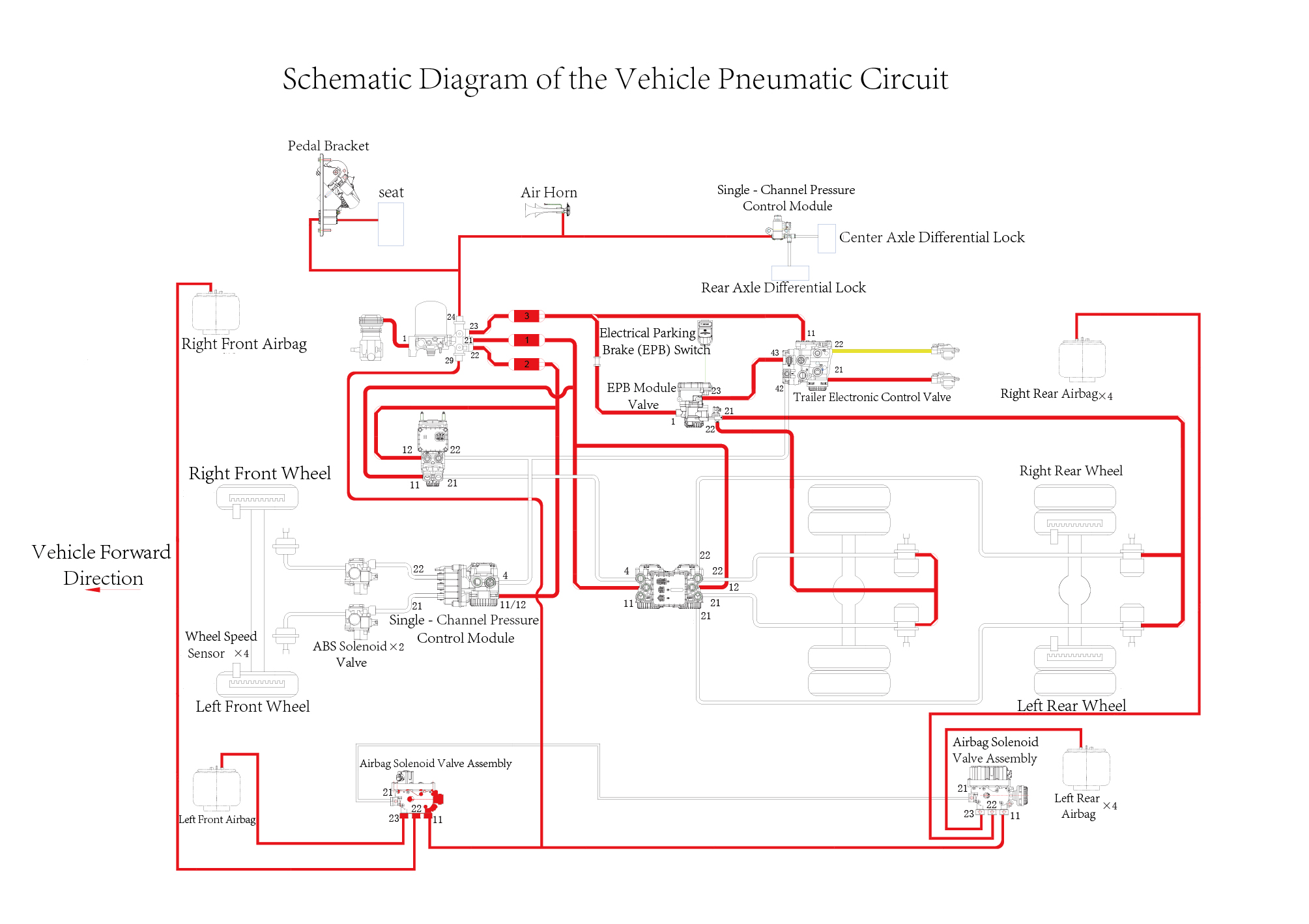
8.14.1 Braking Schematic Diagram
8.14.1.1 Braking Schematic Diagram
8.14.2 Specifications
8.14.2.1 Fastener Specifications
Range Of Torque
Fastener Specifications
Specifications
Foot Pounds of Torque (ft lbs)
The fixing bolt connecting the electric oil
pump to the chassis harness bracket,
and the fixing bolt connecting the brake
(18.5 +/- 2) ft lbs
M8
pedal assembly to the white body
assembly
8.14.3 Decomposition Diagram
8.14.3.1 Decomposition Diagram
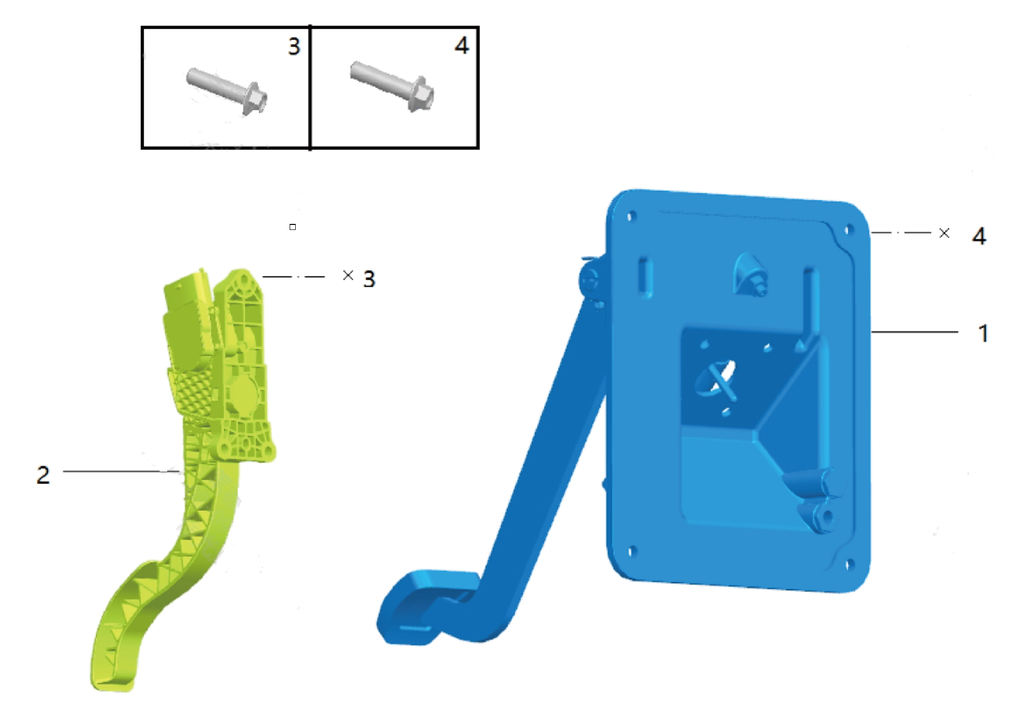
1.
Brake Pedal Assy
3.
Hexagon Flange Bolt
2.
Accelerator Pedal Assy
4.
Hexagon Flange Bolt
8.14.4 Inspect
8.14.4.1 Inspection of Brake System
1. Check the working condition of the vehicle's braking
system. When fully braking, the pedal travel shall not
exceed 3/4 of the full travel.
2. Check the sealing condition of the brake pipeline and joints,
and confirm that there is no leakage.
3. Check the valve joints for looseness or air leakage.
8.14.4.2 Inspection of Brake Pad for Wear
1. Lift the vehicle to the appropriate position and remove the
wheels.
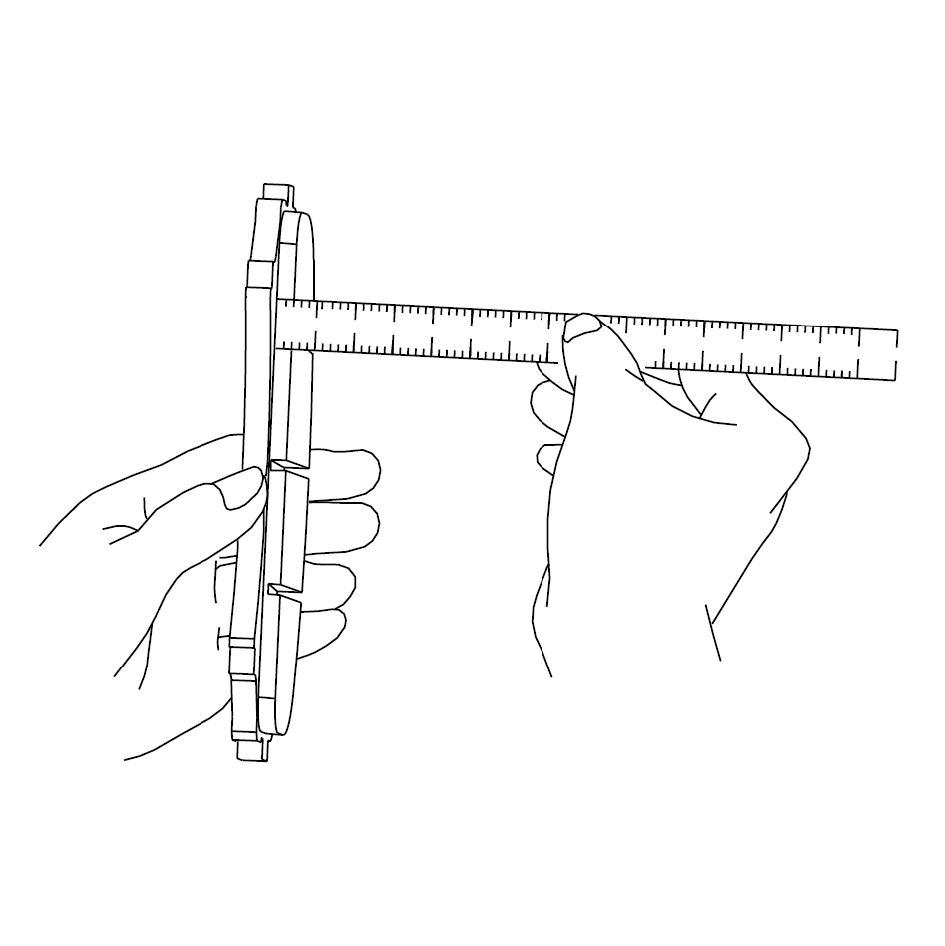
2. Check the thickness of the inner and outer friction plates
through the observation holes on the clamp body.
3. Remove the rear friction plate.
4. Check the thickness of the rear friction plate.
caution
If the thickness is less than the minimum thickness,
replace the friction plates as a set.
If the thickness of the inner and outer friction plates is
less than the specified minimum thickness or if there
is cracking, rupture or damage to the friction plates,
they need to be replaced as a set.
8.14.5 Dismantling and Installation
8.14.5.1 Replacement of Accelerator Pedal Assembly
Assembly
Removal Procedures
1
Open the door.
2
Open the front flip cover plate.
3
Disconnect the battery negative cable.
caution
power down the high-voltage system before
disconnecting the negative pole of the storage
battery.
4
Remove the IP right access cover plate assembly.
5
Remove the IP right front lower trim panel assembly.
6
Remove the right switch panel assembly.
7
Remove the right switch panel lower trim panel assembly.
8
Remove the IP right front upper trim panel assembly.
9
Disconnect 1 harness connector of the accelerator pedal
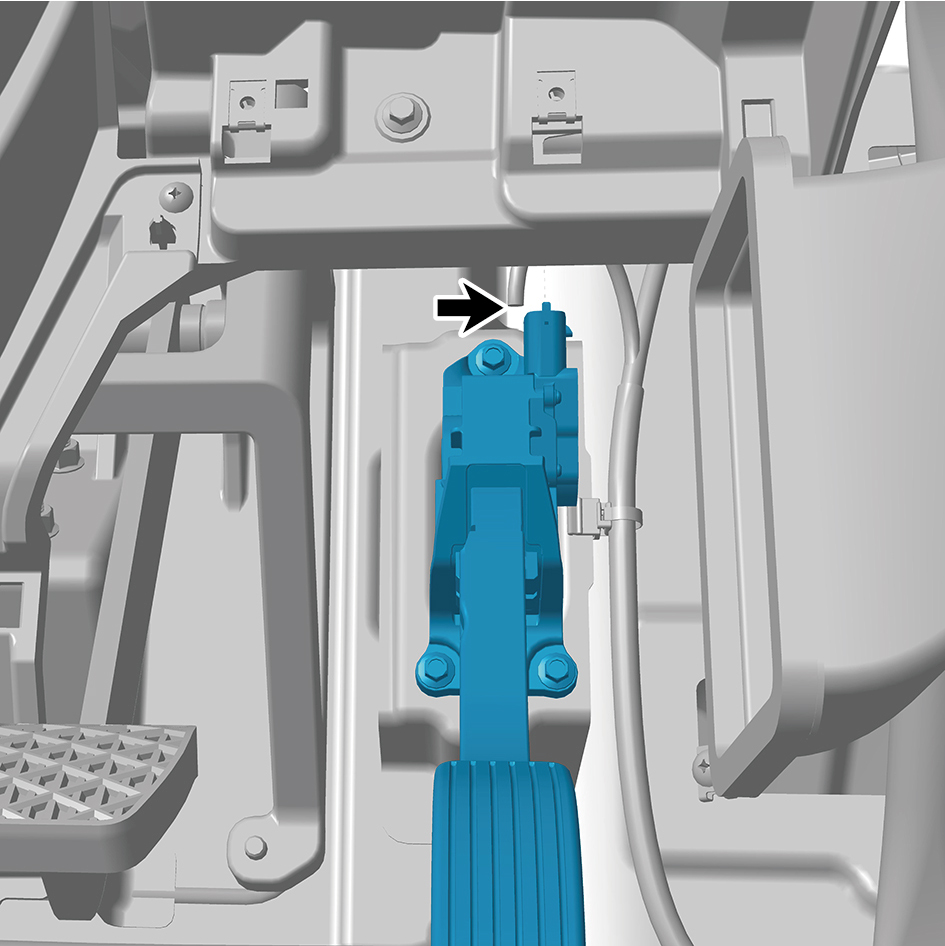
assembly.
10
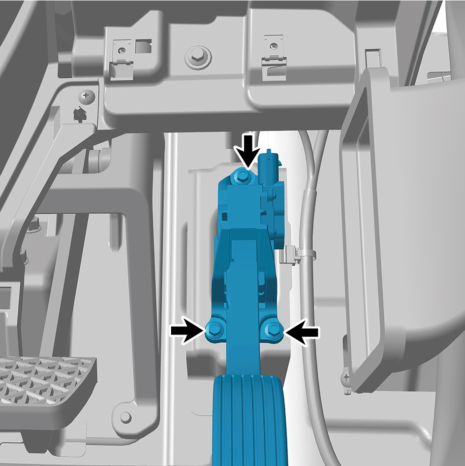
Remove 3 fixing bolts of the accelerator pedal assembly.
11
Remove the accelerator pedal assembly.
Installation Procedures
1
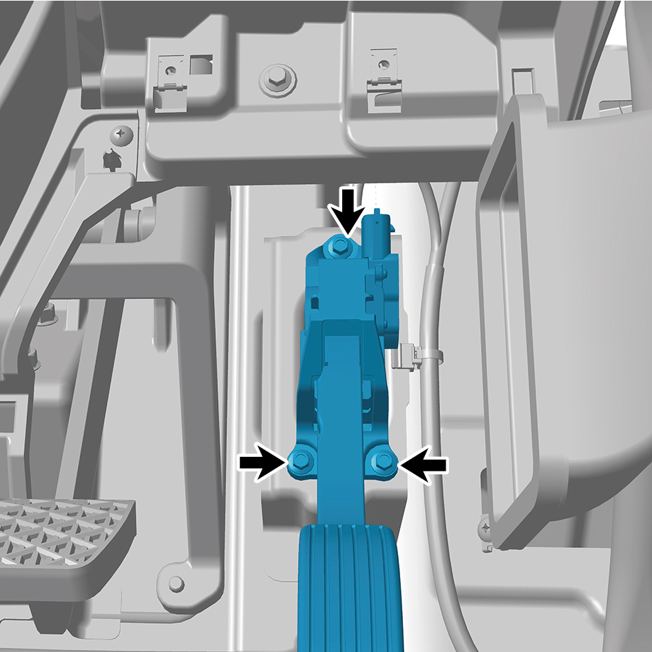
Move the accelerator pedal assembly to the mounting
position.
2
Install 3 fixing bolts of the accelerator pedal assembly.
Torque: 8 +/- .75 (ft lbs)
3
Connect 1 harness connector of the accelerator pedal
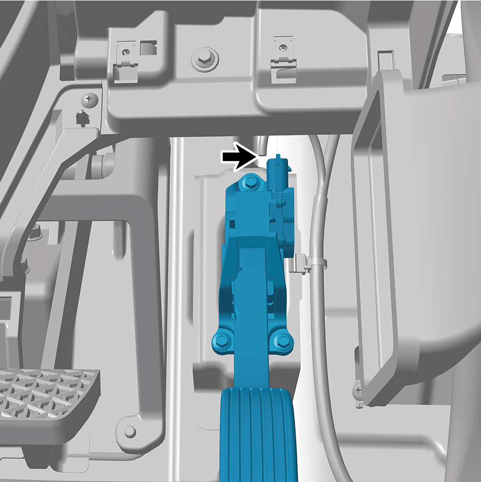
assembly.
caution
The harness is firmly connected following the
principal of "insert until a click is heard for
confirmation".
4
Install the IP right front upper trim panel assembly.
5
Install the right switch panel lower trim panel assembly.
6
Install the right switch panel assembly.
7
Install the IP right front lower trim panel assembly.
8
Install the IP right access cover plate assembly.
9
Connect the battery negative cable.
10
Close the front flip cover plate.
11
Close the door.
8.14.5.2 Replacement of Brake Pedal Assembly
Assembly
Removal Procedures
1
Release air pressure from the brake system.
2
Open the door.
3
Open the front flip cover plate.
4
Disconnect the battery negative cable.
caution
power down the high-voltage system before
disconnecting the negative pole of the storage
battery.
5
Remove the combination switch upper shield assembly.
6
Remove the combination switch lower shield.
7
Remove the IP left access cover plate assembly.
8
Remove the left switch panel assembly.
9
Remove the left switch panel lower trim panel assembly.
10
Remove the IP left front trim panel assembly.
11
Remove the IP right access cover plate assembly.
12
Remove the right switch panel assembly.
13
Remove the right switch panel lower trim panel assembly.
14
Remove the IP right front lower trim panel assembly.
15
Remove the IP right front upper trim panel assembly.
16
Remove the steering column lower shield assembly.
17
Remove the primary wiper arm blade assembly (nozzle
and hose).
18
Remove the front windshield cover plate assembly.
19
Remove the steering column fixing bracket 1.
20
Remove the steering column fixing bracket 2.
21
Remove the brake signal transmitter assembly.
22
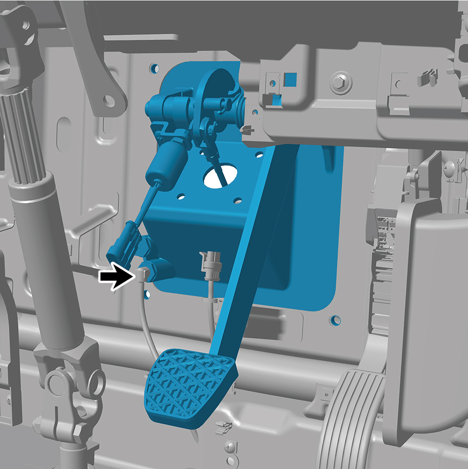
Disconnect 1 harness connector of the brake pedal
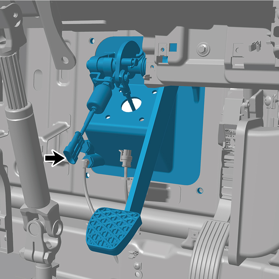
assembly.
23
Disconnect 1 air pipe of the brake pedal assembly.
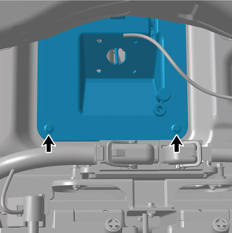
24
Remove 4 fixing bolts of the brake pedal assembly, and
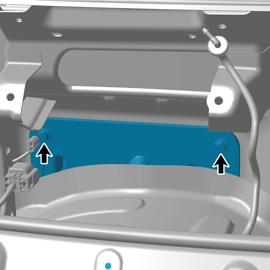
remove the brake pedal assembly.
Installation Procedures
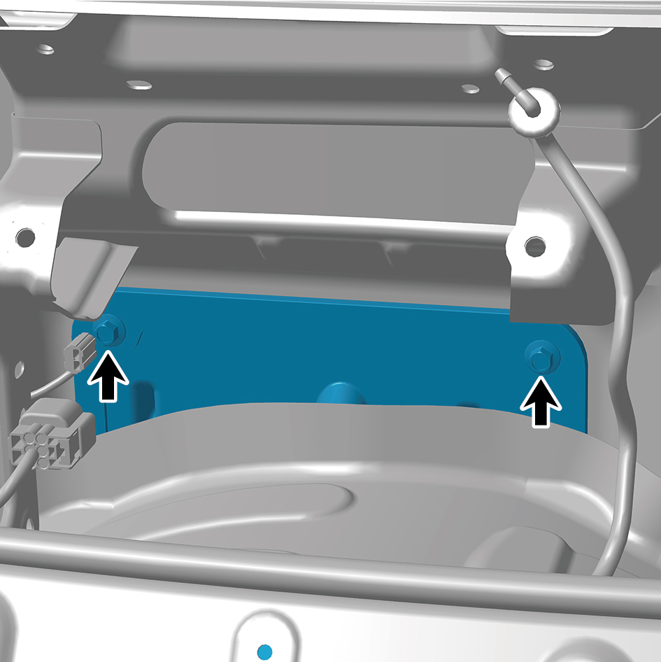
1
Move the brake pedal assembly to the mounting position,
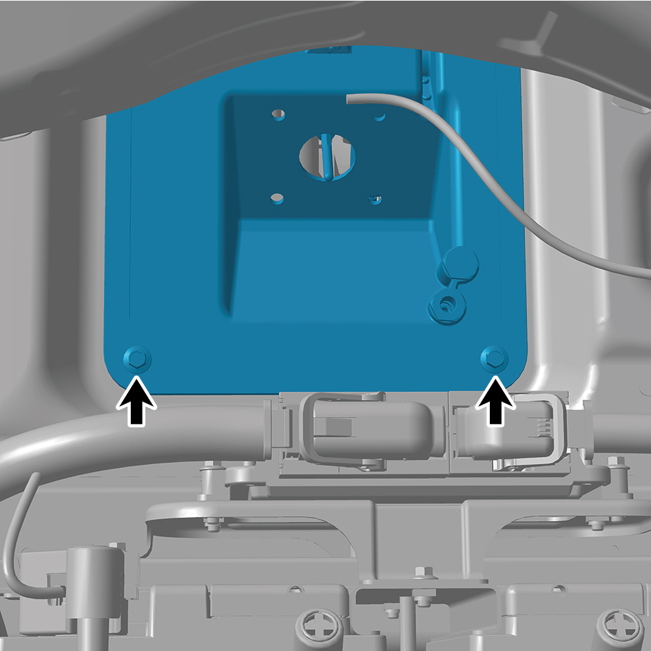
and install the 4 fixing bolts of the brake pedal assembly.
Torque: 18.5 +/- 2 (ft lbs)
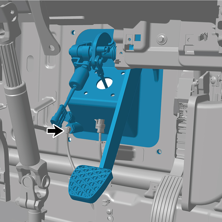
2
Connect 1 air pipe of the brake pedal assembly.
3
Connect 1 harness connector of the brake pedal
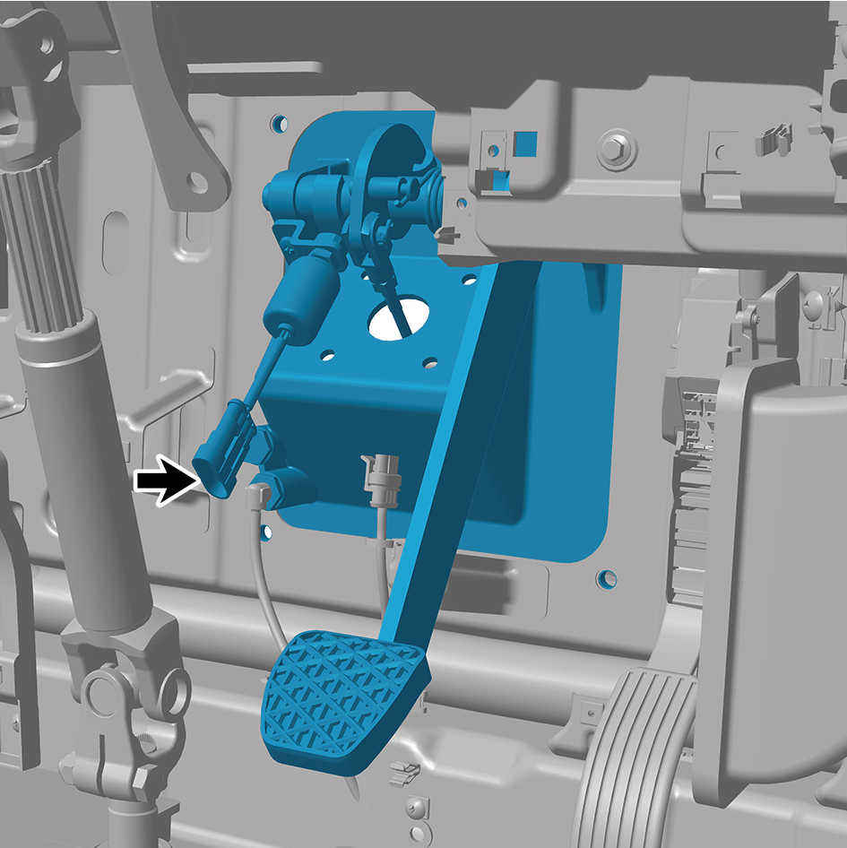
assembly.
caution
The harness is firmly connected following the
principal of "insert until a click is heard for
confirmation".
4
Install the brake signal transmitter assembly.
5
Install the steering column fixing bracket 2.
6
Install the steering column fixing bracket 1.
7
Install the front windshield cover plate assembly.
8
Install the primary wiper arm blade assembly (nozzle and
hose).
9
Install the steering column lower shield assembly.
10
Install the IP right front upper trim panel assembly.
11
Install the IP right front lower trim panel assembly.
12
Install the right switch panel lower trim panel assembly.
13
Install the right switch panel assembly.
14
Install the IP right access cover plate assembly.
15
Install the IP left front trim panel assembly.
16
Install the left switch panel lower trim panel assembly.
17
Install the left switch panel assembly.
18
Install the IP left access cover plate assembly.
19
Install the combination switch lower shield.
20
Install the combination switch upper shield assembly.
21
Connect the battery negative cable.
22
Close the front flip cover plate.
23
Close the door.