← Back to Contents
8 Chassis / 8.15 Brake Line Device | PDF pages 2104-2130
8.15 Brake Line Device
8.15 Brake Line Device
8.15.1 Specifications
8.15.1.1 Fastener Specifications
Range Of Torque
Fastener Specifications
Specifications
Foot Pounds of Torque (ft lbs)
The fixing bolt connecting the ABS
solenoid valve bracket to the frame
103 +/-7.52 (ft lbs)
M14
assembly
Fixed bolts connecting the single
70 +/- 3.5 (ft lbs)
channel module assembly to the single
M12
channel module bracket
The fixing bolts connecting the dual
70 +/- 3.5 (ft lbs)
channel module assembly and the dual
M12
channel module bracket
The fixing bolt connecting the ABS
18.5 +/- 2 (ft lbs)
M8
solenoid valve assembly to the ABS
solenoid valve bracket
The fixing bolts connecting the trailer
18.5 +/- 2 (ft lbs)
M8
module assembly to the trailer
connection bracket
Pressure sensor fixed on the three-way
joint interface of the gas storage
18.5 +/- 2 (ft lbs)
M12
cylinder
Low pressure alarm switch fixed on the
18.5 +/- 2 (ft lbs)
M12
valve tee joint interface
Test connector fixed on T-shaped tee
18.5 +/- 2 (ft lbs)
M12
The fixing nut for the direct connector
37 +/- 3.5 (ft lbs)
M18
fixed trailer connector bracket
connection
Bent joint fixed on valve interface
22 +/- 2 (ft lbs)
M22
Fixed on the T-shaped joint at the air
18.5 +/- 2 (ft lbs)
M16
chamber interface
The fixing nut of the brake spiral pipe
37 +/- 3.5 (ft lbs)
M18
assembly
Fixed nut of brake hose assembly
37 +/- 3.5 (ft lbs)
M18
8.15.2 Decomposition Diagram
8.15.2.1 Decomposition Diagram
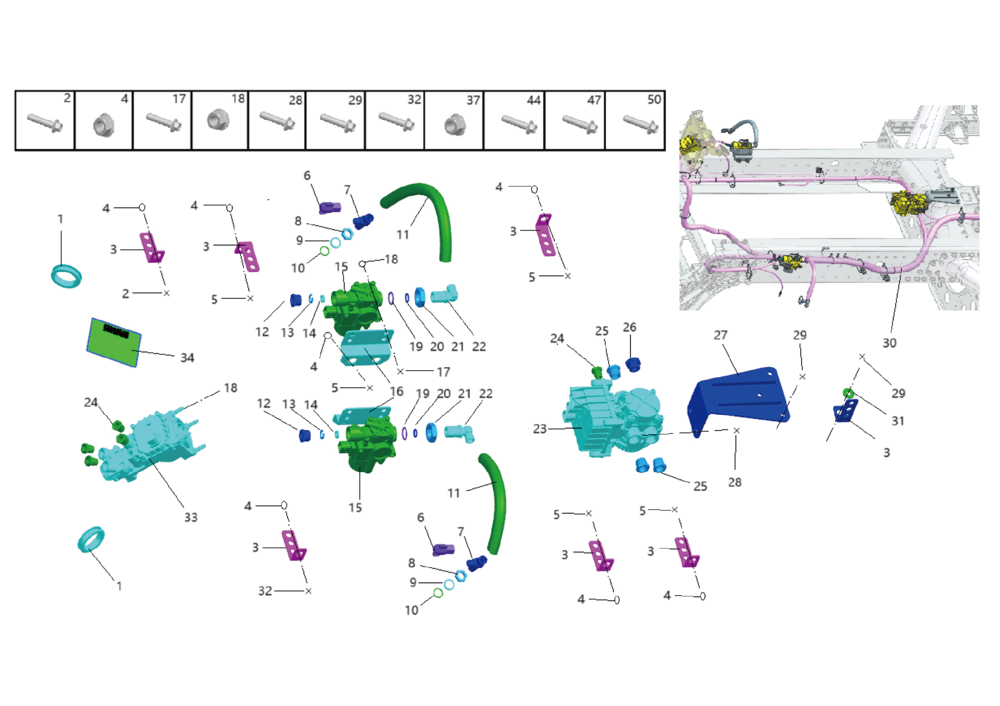
1.
20.
Through The Hole Sheath
Sealing Gasket
2.
Hexagon Flange Bolt
21.
Hex Thin Nut
3.
Wire Harness Bracket
22.
Bend Joint
4.
23.
Hexagon Flange Lock Nut_All Metal
Ebs Axle Modulator Assy
5.
24.
Hexagon Flange Bolt
Nut Seat NG8
6.
25.
Test Connector
Nut Seat Ng12
7.
26.
Plug
Sealing Gasket
8.
Hex Thin Nut
27.
Ebs Axle Modulator Bracket
9.
28.
Hexagon Flange Bolt
Sealing Gasket
10.
29.
Hexagon Flange Bolt
O-Ring
11.
Brake Hose Assy
30.
Brake Bundle Assy
12.
31.
Large Washer
Nut Seat Ng12
13.
32.
Hexagon Flange Bolt
Snap Ring Ng12
14.
Washer Ng12
33.
Brake Signal Transmitter Assy
15.
34.
ABS Solenoid Valve Assy
Brake System Parameter Label
16.
37.
Hexagon Flange Bolt
Solenoid Modulator Valve Brakecket
17.
Hexagon Flange Bolt
44.
Hexagon Flange Bolt
18.
Hexagon Flange Lock Nut_All Metal
47.
Hexagon Flange Bolt
19.
50.
Hexagon Flange Bolt
O-Ring
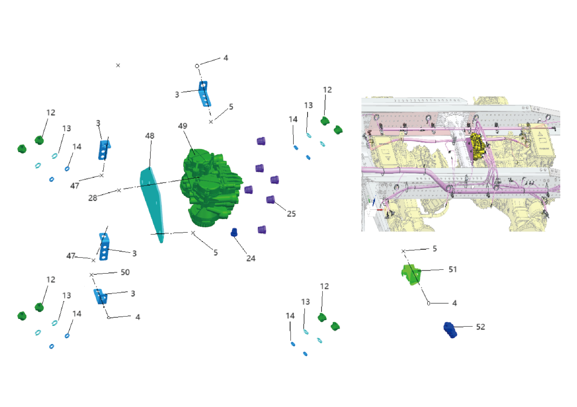
3.
Wire Harness Bracket
28.
Hexagon Flange Bolt
4.
Hexagon Flange Lock Nut_All Metal
47.
Hexagon Flange Bolt
5.
Hexagon Flange Bolt
48.
Ebs Axle Modulator Bracket
12.
49.
Ebs Axle Modulator Assy
Nut Seat Ng12
13.
50.
Hexagon Flange Bolt
Snap Ring Ng12
14.
Washer Ng12
51.
Bundle Fixing Bracket
24.
52.
Nut Seat NG8
Low Pressure Warning Switch
25.
Nut Seat Ng12
8.15.3 Dismantling and Installation
8.15.3.1 Replacement of Brake Signal Transmitter Assembly
Transmitter Assembly
Removal Procedures
1
Open the door.
2
Open the front flip cover plate.
3
Disconnect the battery negative cable.
caution
power down the high-voltage system before
disconnecting the negative pole of the storage
battery.
4
Remove the combination switch upper shield assembly.
5
Remove the combination switch lower shield.
6
Remove the IP left access cover plate assembly.
7
Remove the left switch panel assembly.
8
Remove the left switch panel lower trim panel assembly.
9
Remove the IP left front trim panel assembly.
10
Remove the IP right access cover plate assembly.
11
Remove the right switch panel assembly.
12
Remove the right switch panel lower trim panel assembly.
13
Remove the IP right front lower trim panel assembly.
14
Remove the IP right front upper trim panel assembly.
15
Remove the steering column lower shield assembly.
16
Disconnect 1 harness connector of the brake signal
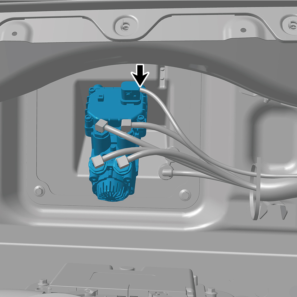
transmitter assembly.
17
Disconnect 4 air pipes of the brake signal transmitter
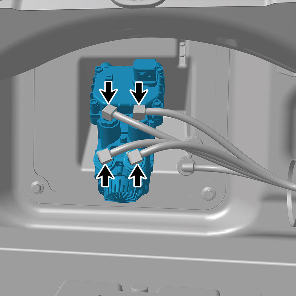
assembly.
18
Remove 4 fixing nuts of the brake signal transmitter
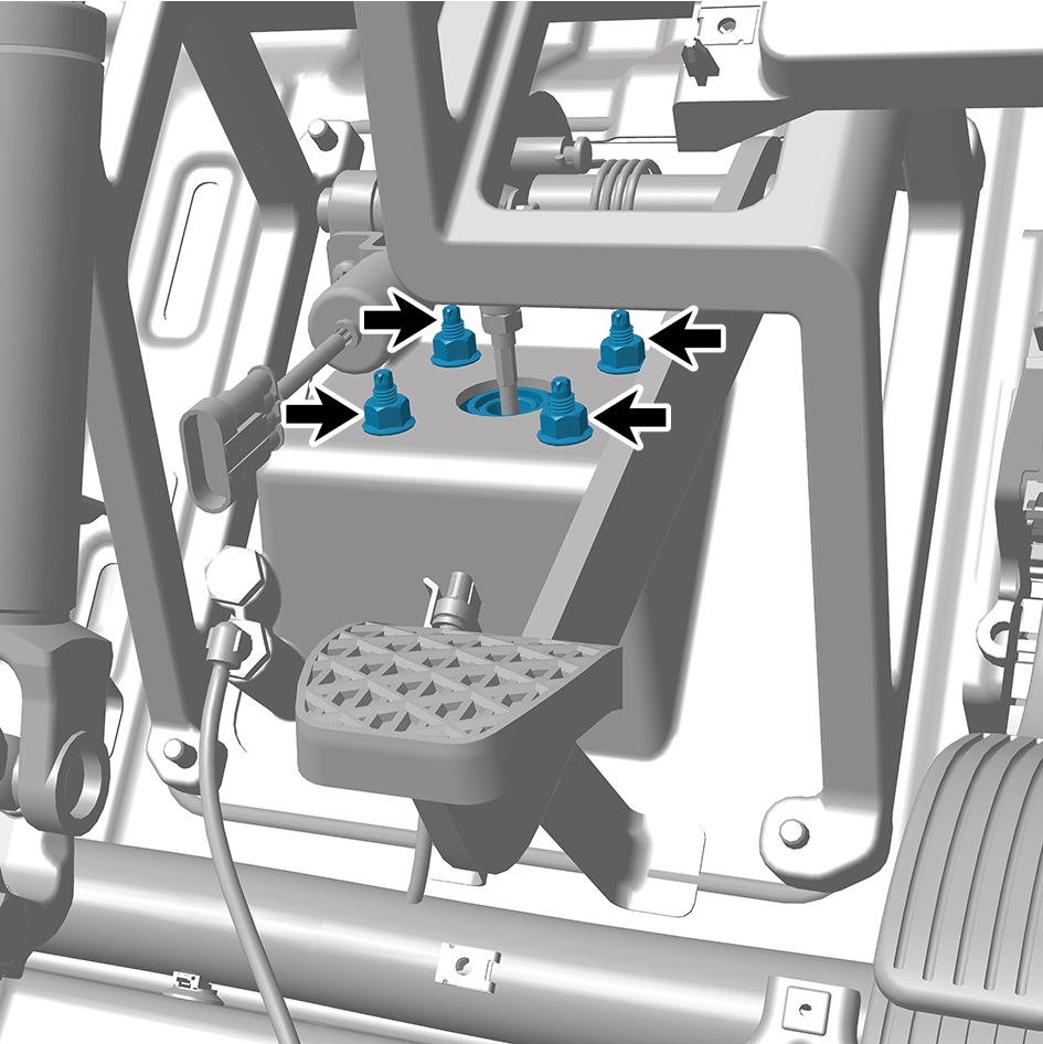
assembly.
19
Remove the brake signal transmitter assembly.
Installation Procedures
1
Move the brake signal transmitter assembly to the
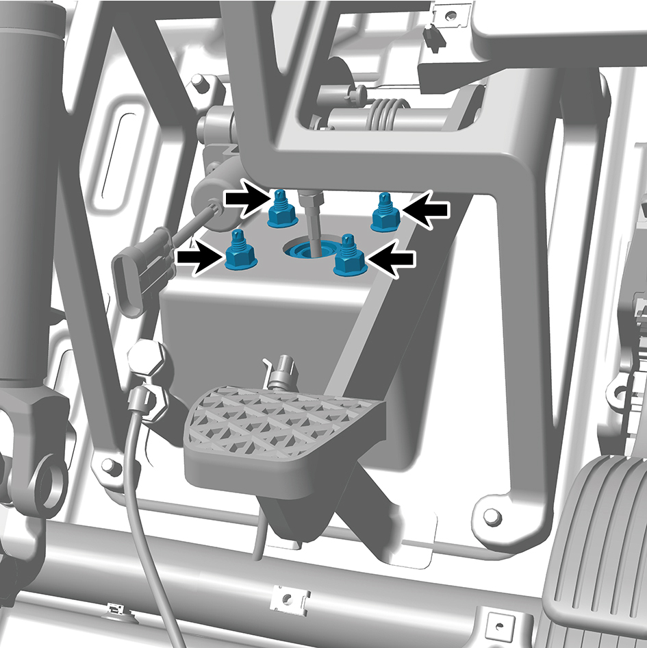
mounting position.
2
Install 4 fixing nuts of the brake signal transmitter
assembly.
Torque: 18.5 +/- 2 (ft lbs)
3
Connect 4 air pipes of the brake signal transmitter
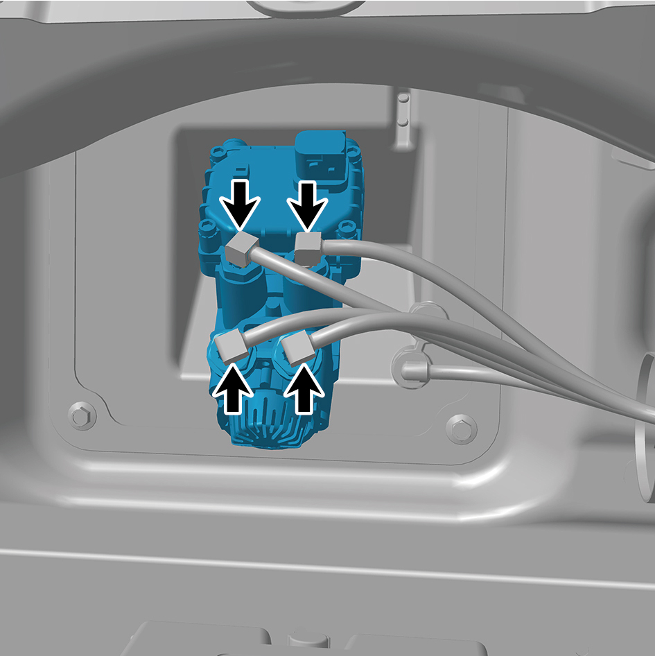
assembly.
4
Connect 1 harness connector of the brake signal
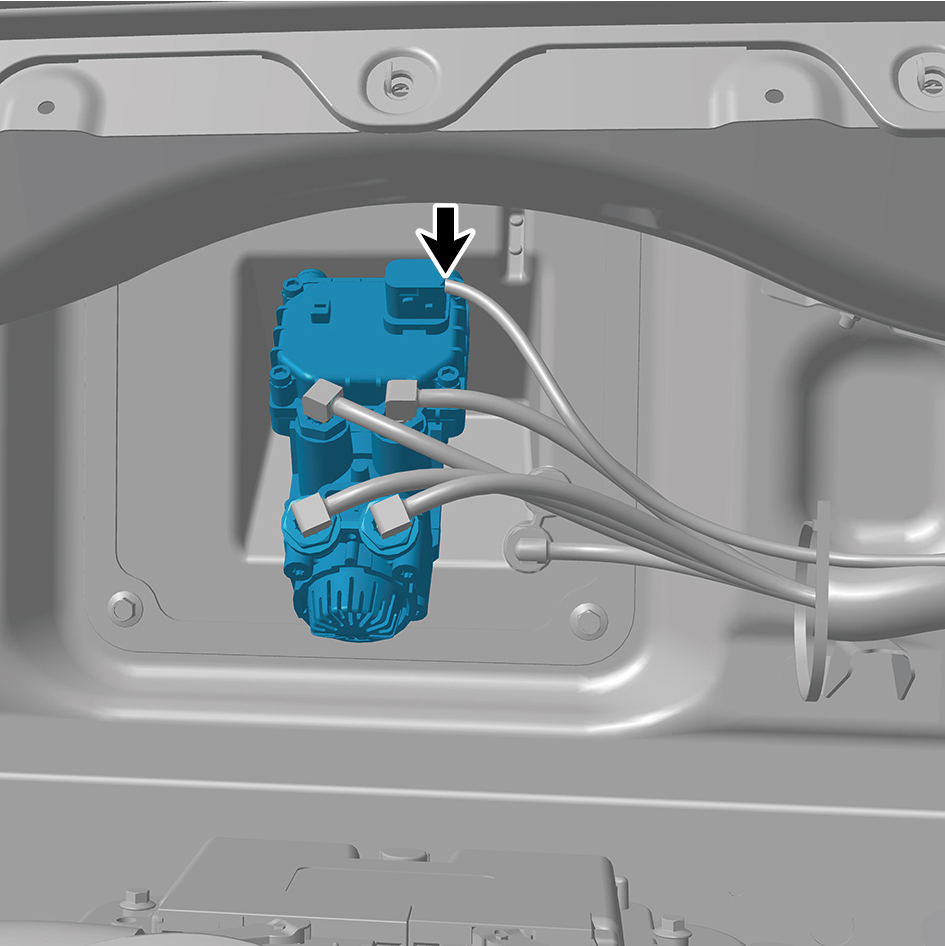
transmitter assembly.
caution
The harness is firmly connected following the
principal of "insert until a click is heard for
confirmation".
5
Install the steering column lower shield assembly.
6
Install the IP right front upper trim panel assembly.
7
Install the IP right front lower trim panel assembly.
8
Install the right switch panel lower trim panel assembly.
9
Install the right switch panel assembly.
10
Install the IP right access cover plate assembly.
11
Install the IP left front trim panel assembly.
12
Install the left switch panel lower trim panel assembly.
13
Install the left switch panel assembly.
14
Install the IP left access cover plate assembly.
15
Install the combination switch lower shield.
16
Install the combination switch upper shield assembly.
17
Connect the battery negative cable.
18
Close the front flip cover plate.
19
Close the door.
8.15.3.2 Replacement of ABS Solenoid Valve Assembly
Assembly
Removal Procedures
1
Release air pressure from the brake system.
2
Open the door.
3
Open the front flip cover plate.
4
Disconnect the battery negative cable.
caution
power down the high-voltage system before
disconnecting the negative pole of the storage
battery.
5
Disconnect 1 harness connector of the ABS solenoid
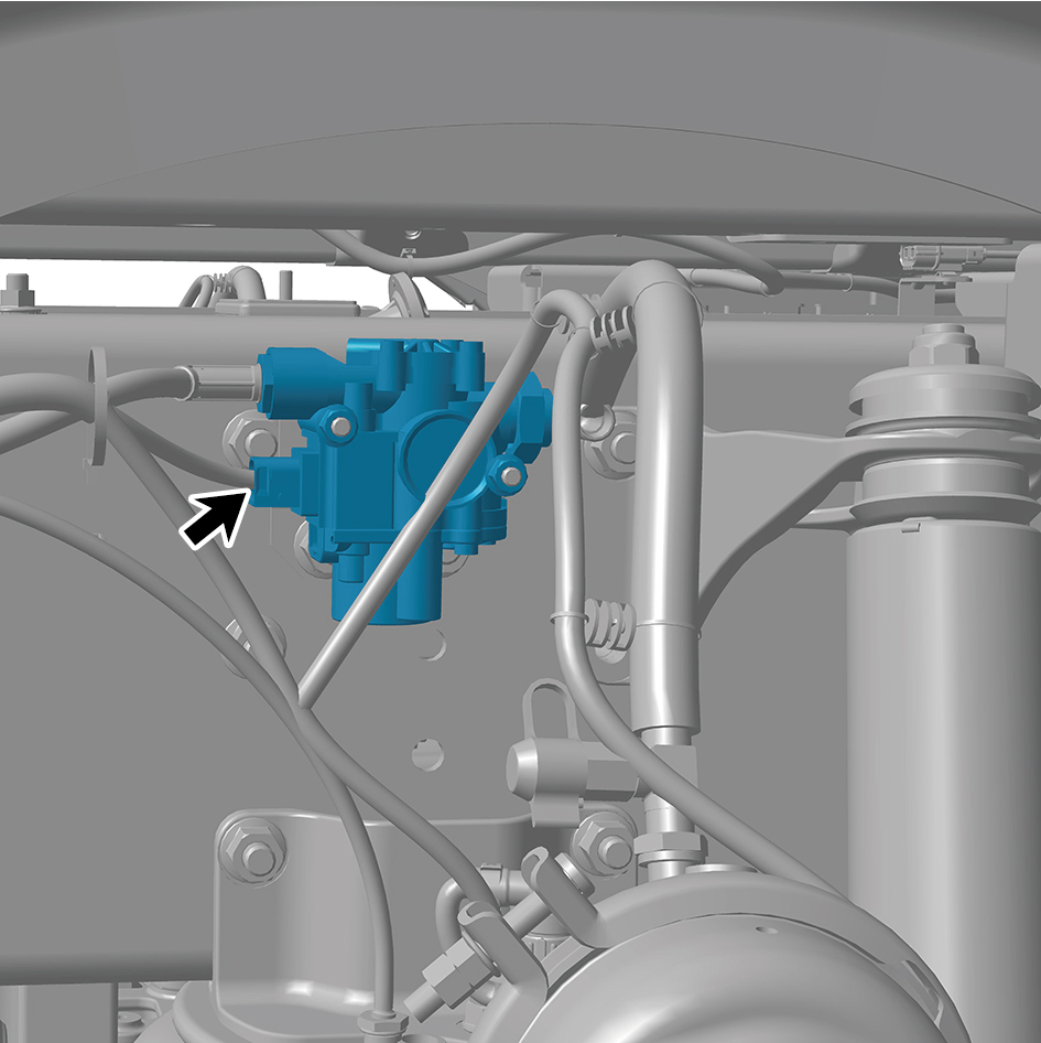
valve assembly.
6
Disconnect 2 air pipes of the ABS solenoid valve
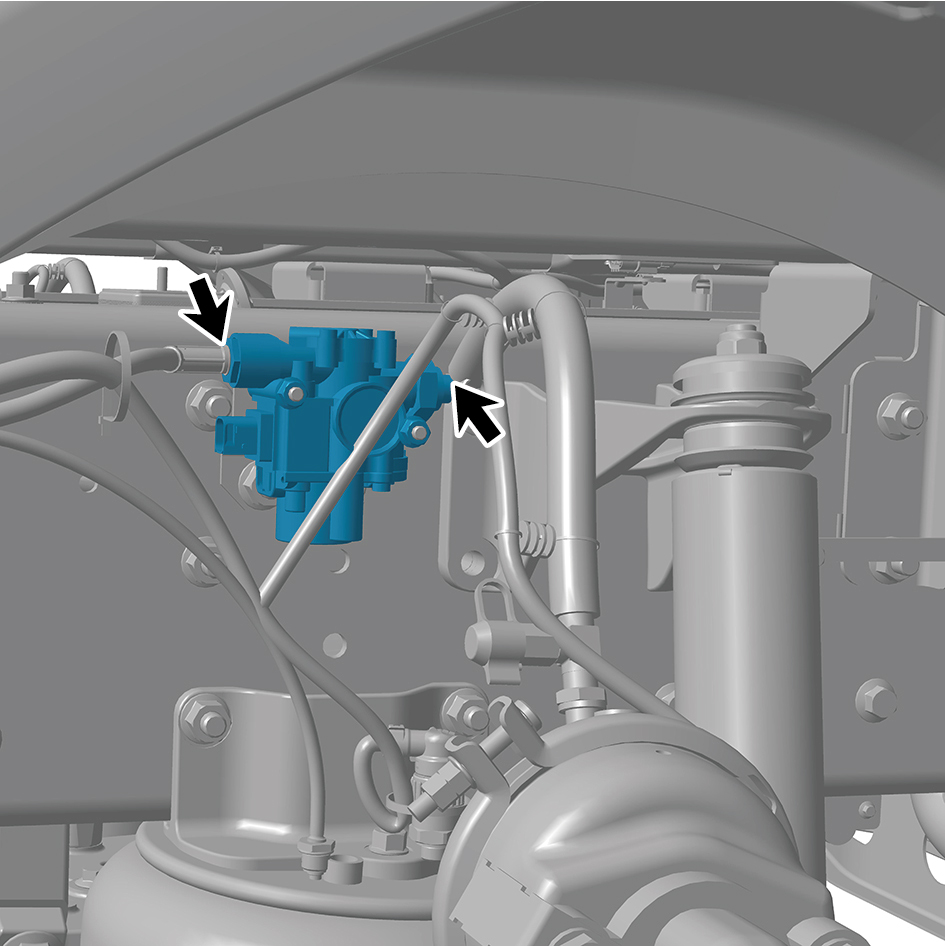
assembly.
7
Remove 2 fixing nuts of the ABS solenoid valve assembly.
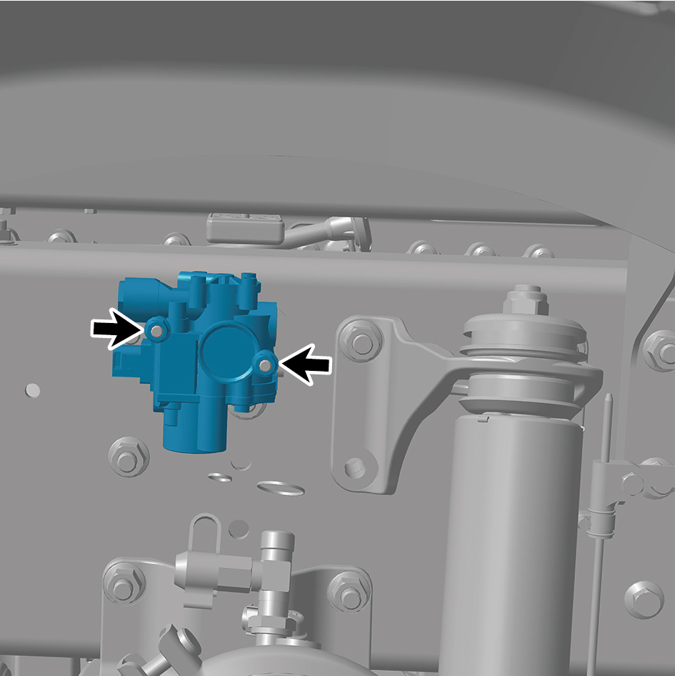
8
Remove the ABS solenoid valve assembly.
Installation Procedures
1
Move the ABS solenoid valve assembly to the mounting
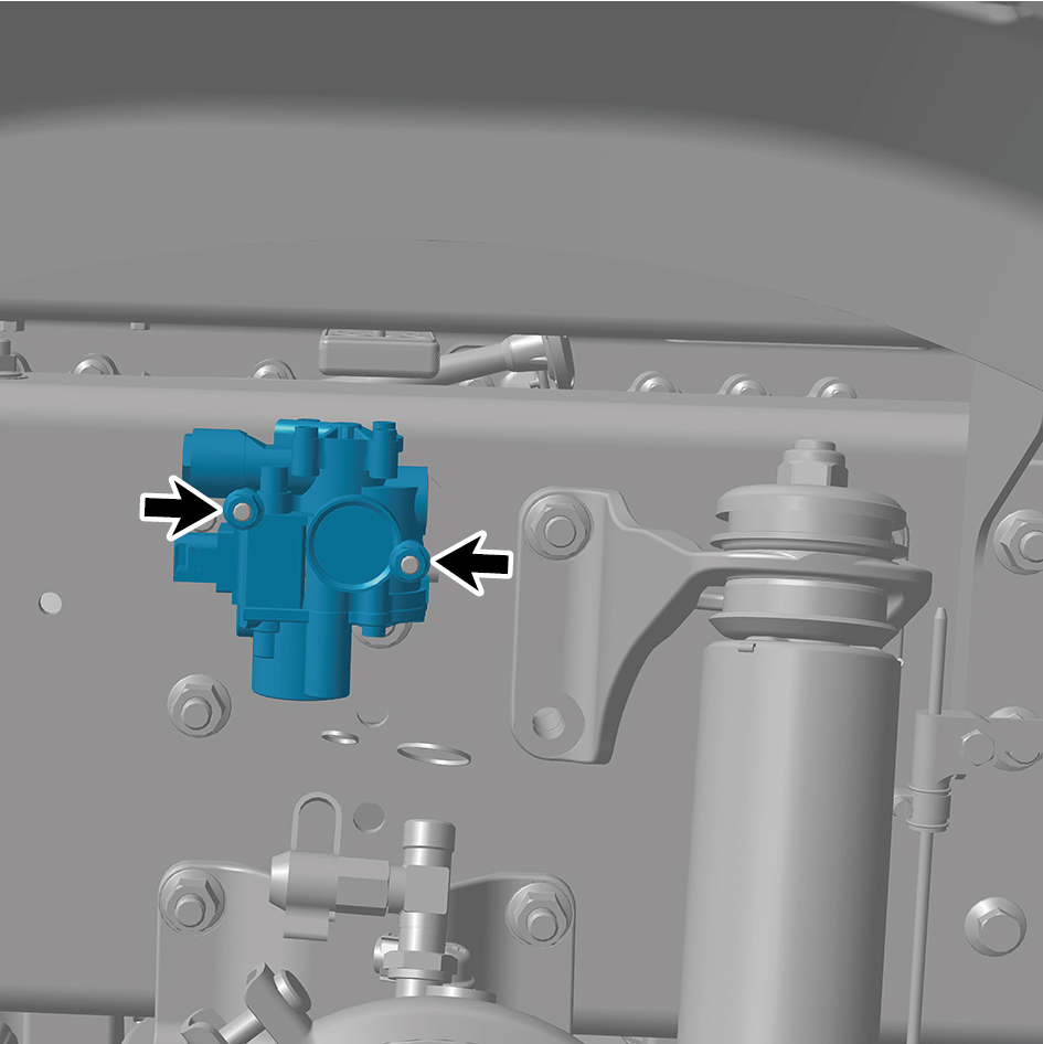
position.
2
Install 2 fixing nuts of the ABS solenoid valve assembly.
Torque: 44 +/- 3.5 (ft lbs)
3
Connect 2 air pipes of the ABS solenoid valve assembly.
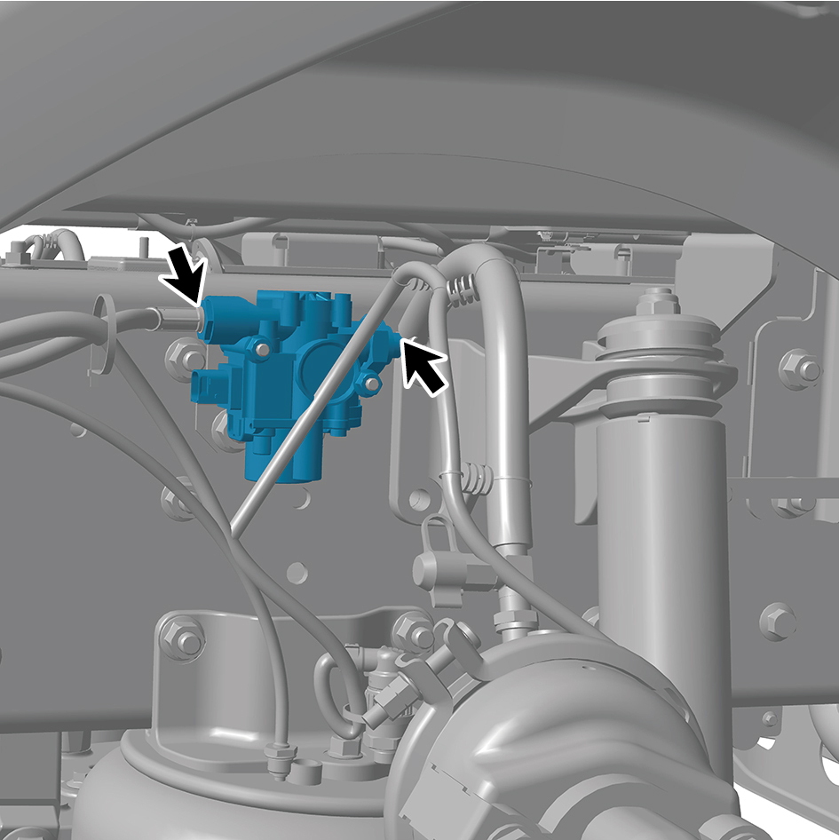
4
Connect 1 harness connector of the ABS solenoid valve
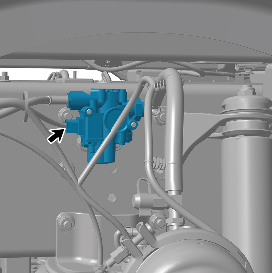
assembly.
caution
The harness is firmly connected following the
principal of "insert until a click is heard for
confirmation".
5
Connect the battery negative cable.
6
Close the front flip cover plate.
7
Close the door.
8.15.3.3 Replacement of Brake Hose Assembly
Assembly
Removal Procedures
1
Release air pressure from the brake system.
2
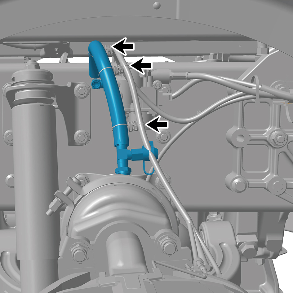
Disconnect 3 harness straps of the brake hose assembly.
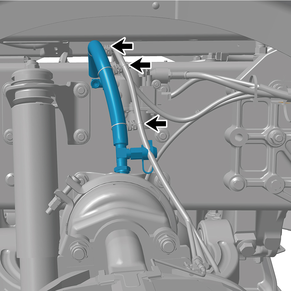
3
Remove 2 joints of the brake hose assembly.
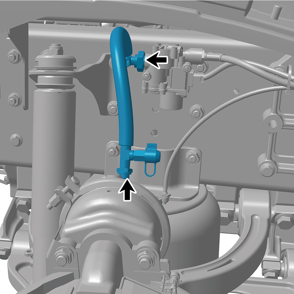
4
Remove the brake hose assembly.
Installation Procedures
1
Move the brake hose assembly to the mounting position.
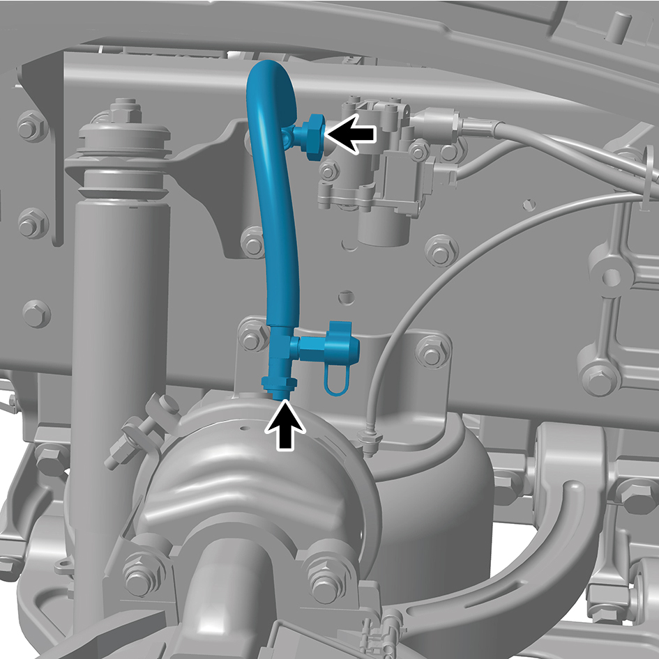
2
Install 2 joints of the brake hose assembly.
3
Connect 3 harness straps of the brake hose assembly.
8.15.3.4 Replacement of Single Channel Module Assembly
Module Assembly
Removal Procedures
1
Release air pressure from the brake system.
2
Open the door.
3
Open the front flip cover plate.
4
Disconnect the battery negative cable.
5
Remove the single channel module assembly with
bracket.
6
Disconnect 2 harness connectors of the single channel
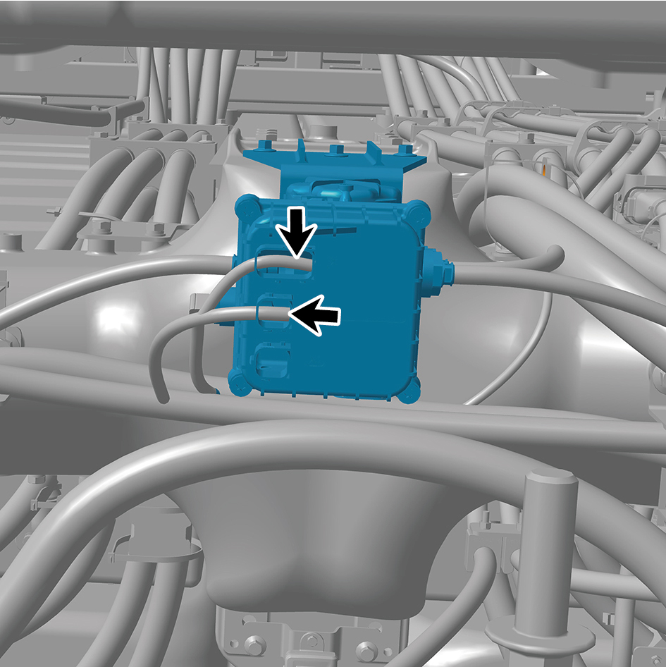
module assembly.
7
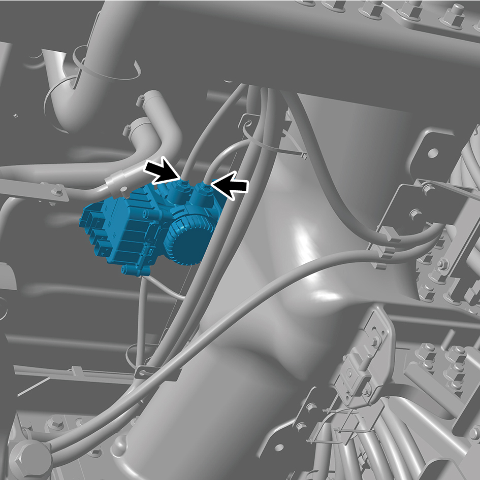
Disconnect 4 air pipes of the single channel module
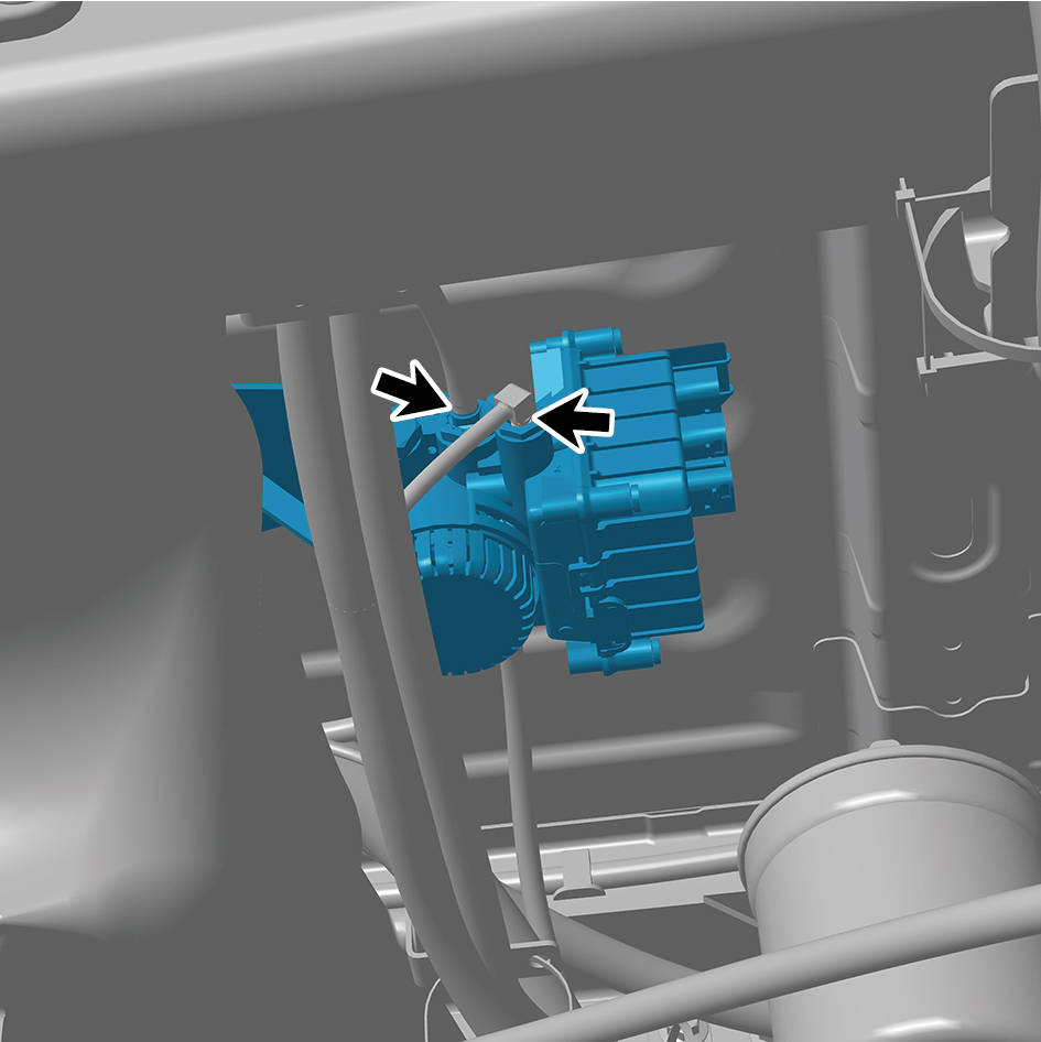
assembly.
8
Remove 3 fixing bolts of the single channel module
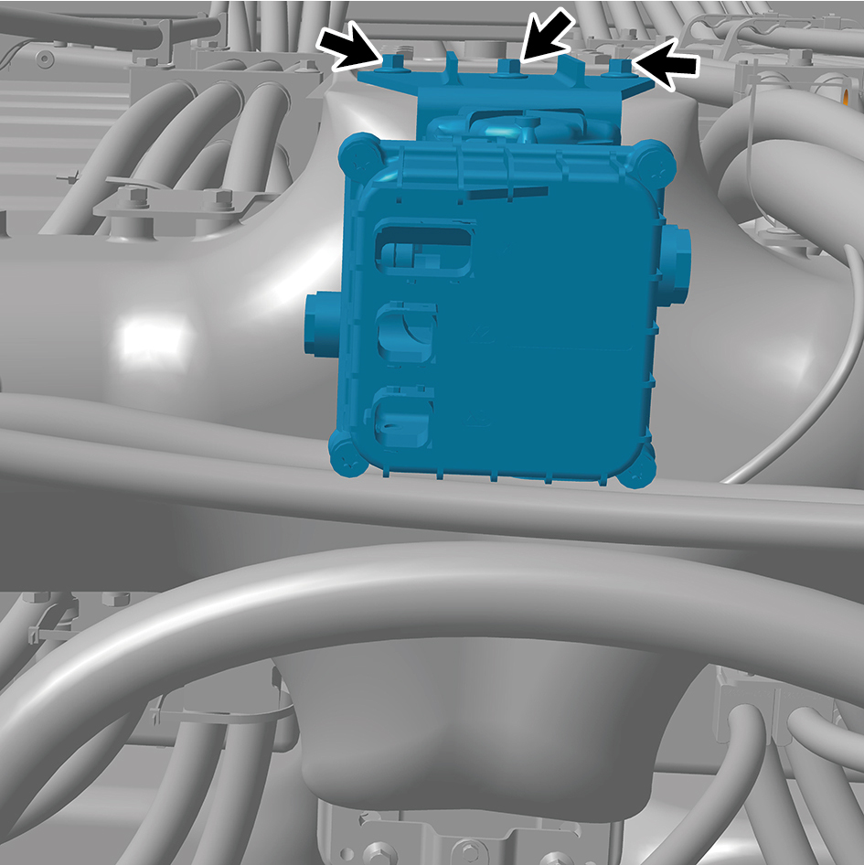
assembly.
9
Remove the single channel module assembly.
Installation Procedures
1
Move the single channel module assembly to the
mounting position.
2
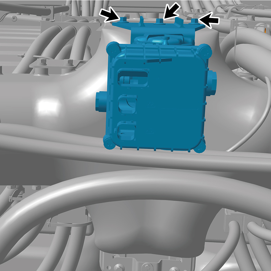
Install 3 fixing bolts of the single channel module
assembly.
Torque:18.5 +/- 2 (ft lbs)
3
Connect 4 air pipes of the single channel module
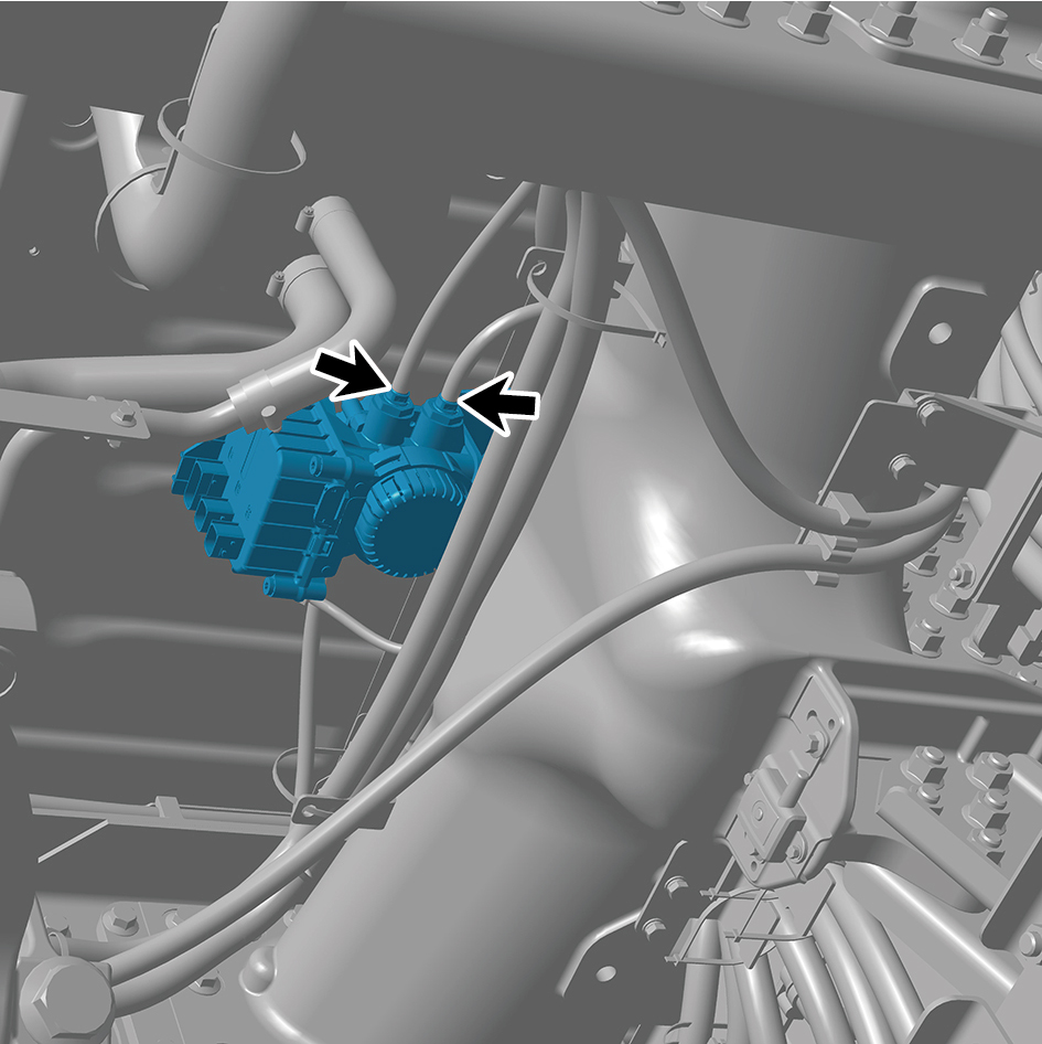
assembly.
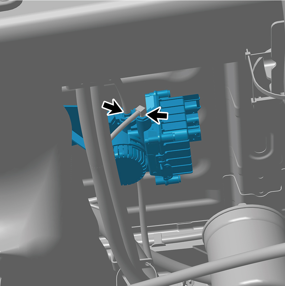
4
Connect 2 harness connectors of the single channel
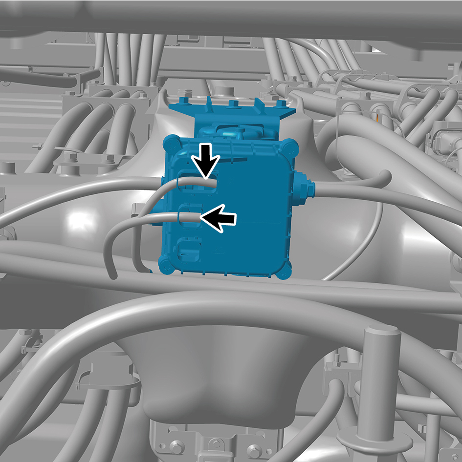
module assembly.
caution
The harness is firmly connected following the
principal of "insert until a click is heard for
confirmation".
5
Install the single channel module assembly with bracket.
6
Connect the battery negative cable.
7
Close the front flip cover plate.
8
Close the door.
8.15.3.5 Replacement of Trailer Control Module Assembly
Module Assembly
Removal Procedures
1
Release air pressure from the brake system.
2
Open the door.
3
Open the front flip cover plate.
4
Disconnect the battery negative cable.
caution
power down the high-voltage system before
disconnecting the negative pole of the storage
battery.
5
Remove the back integrated bracket side cover plate
assembly (left).
6
Remove the back integrated bracket side cover plate
assembly (right).
7
Remove the back integrated bracket middle cover plate
assembly.
8
Disconnect 1 harness connector of the trailer control
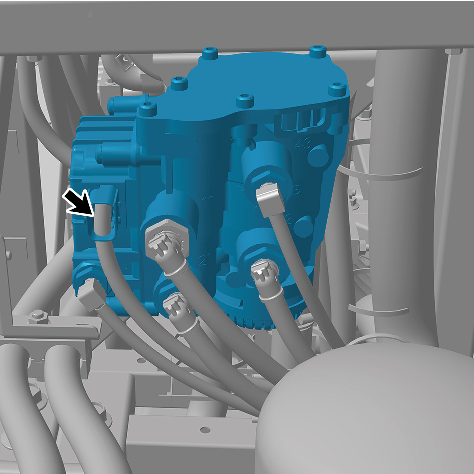
module assembly.
9
Disconnect 5 air pipes of the trailer control module
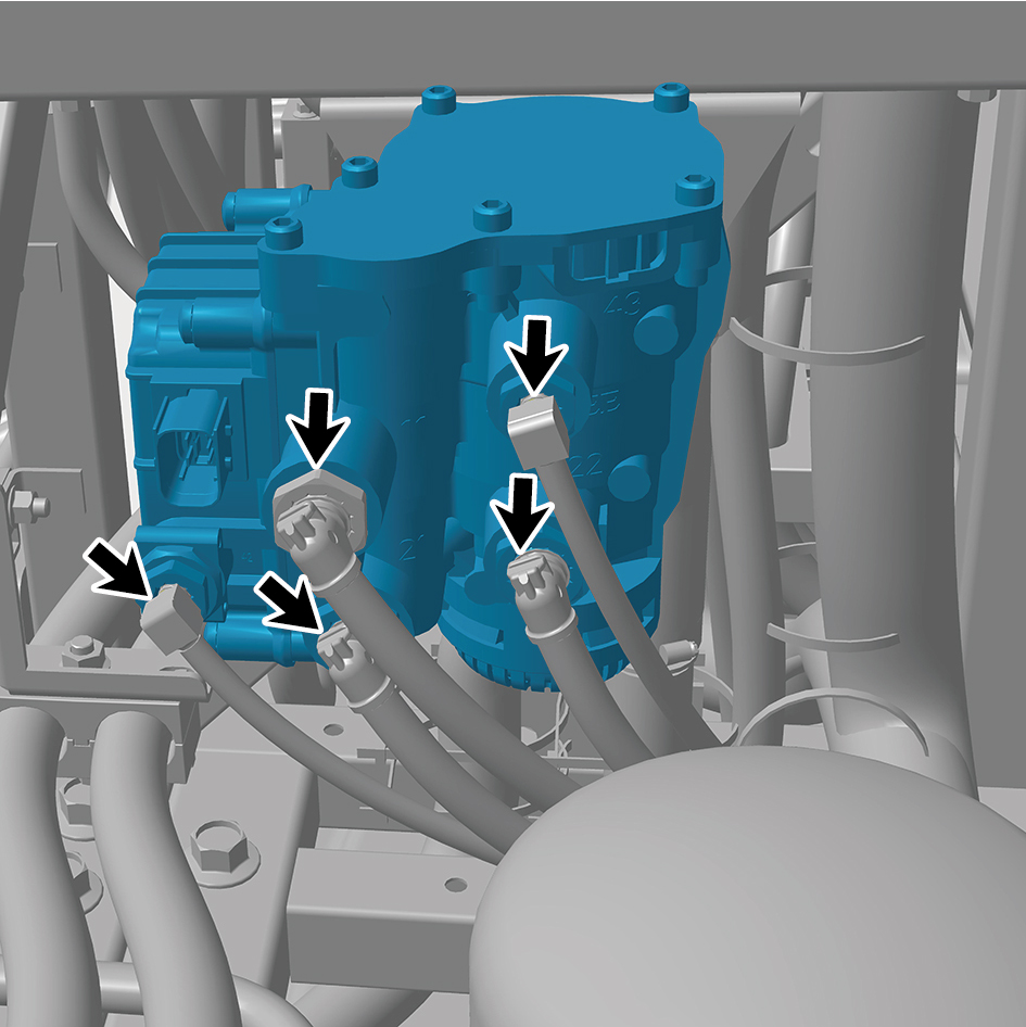
assembly.
10
Remove 3 fixing nuts of the trailer control module
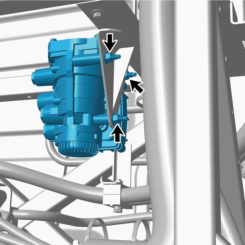
assembly.
11
Remove the trailer control module assembly.
Installation Procedures
1
Move the trailer control module assembly to the mounting
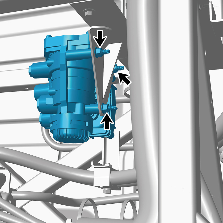
position.
2
Install 3 fixing nuts of the trailer control module assembly.
Torque: 103 +/- 7.5 (ft lbs)
3
Connect 5 air pipes of the trailer control module assembly.
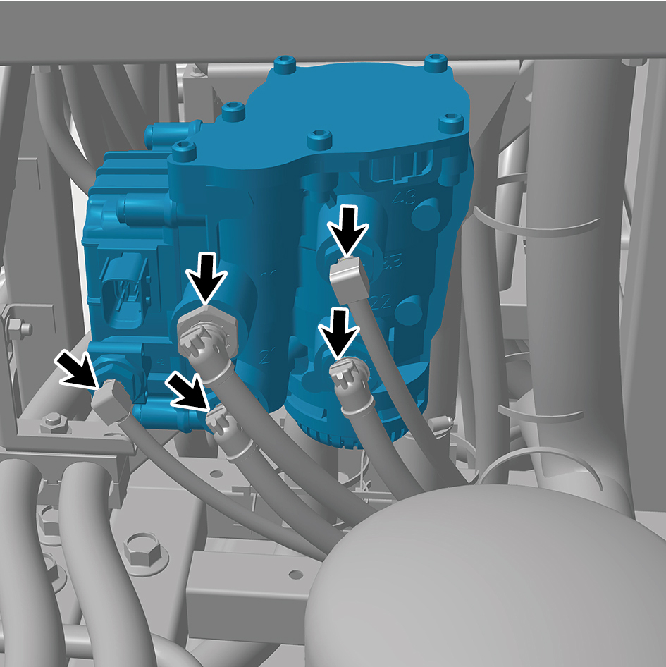
4
Connect 1 harness connector of the trailer control module
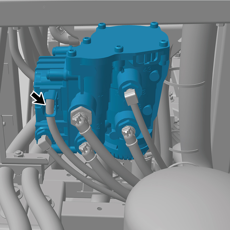
assembly.
caution
The harness is firmly connected following the
principal of "insert until a click is heard for
confirmation".
5
Install the back integrated bracket middle cover plate
assembly.
6
Install the back integrated bracket side cover plate
assembly (right).
7
Install the back integrated bracket side cover plate
assembly (left).
8
Connect the battery negative cable.
9
Close the front flip cover plate.
10
Close the door.
8.15.3.6 Replacement of Brake Spiral Tube Assembly
Assembly
Removal Procedures
1
Release air pressure from the brake system.
2
Disconnect 2 air pipes of the brake spiral tube assembly.
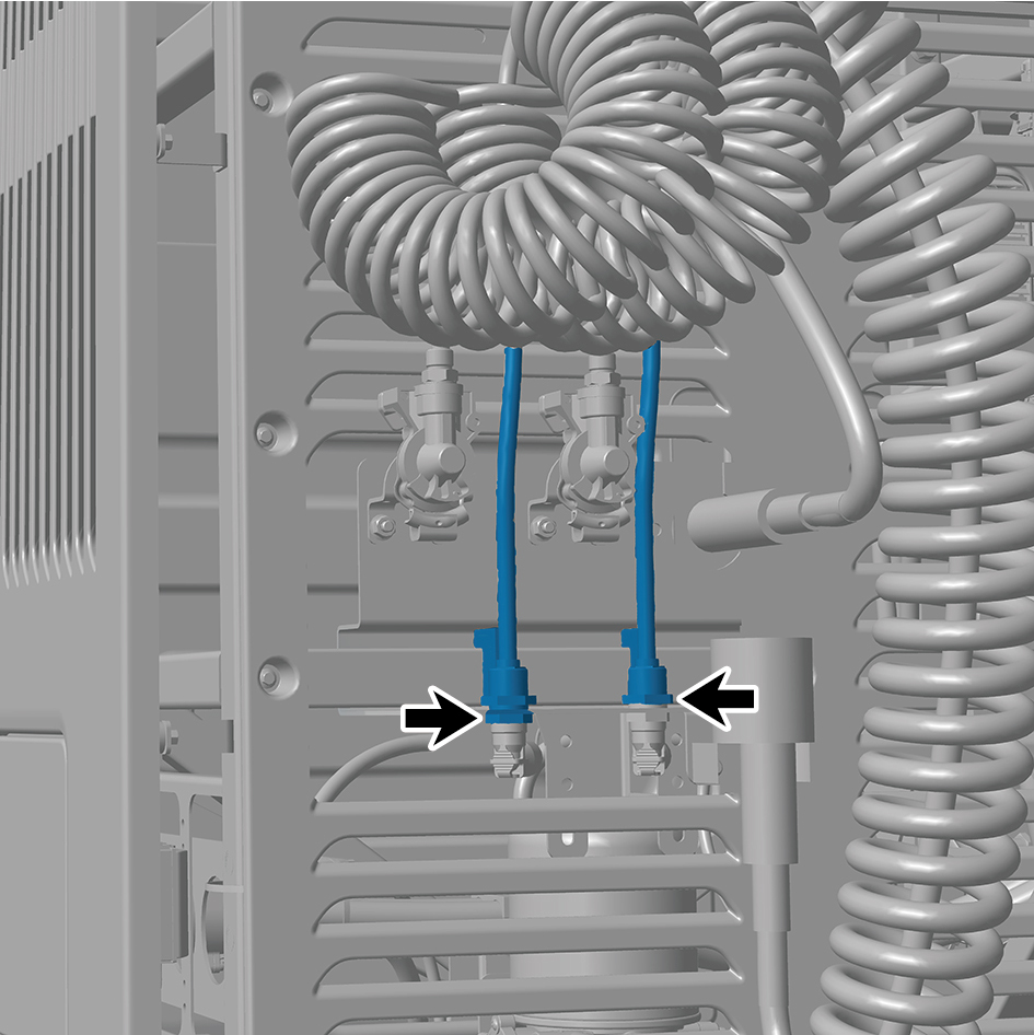
3
Remove the brake spiral tube assembly.
Installation Procedures
1
Move the brake spiral tube assembly to the mounting
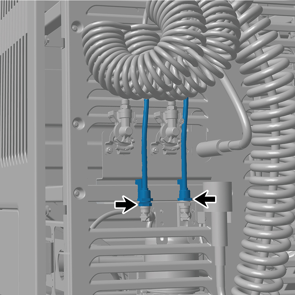
position.
2
Connect 2 air pipes of the brake spiral tube assembly.
8.15.3.7 Replacement of Trailer Connector Assembly
Assembly
Removal Procedures
1
Release air pressure from the brake system.
2
Disconnect 1 air pipe of the trailer connector assembly.
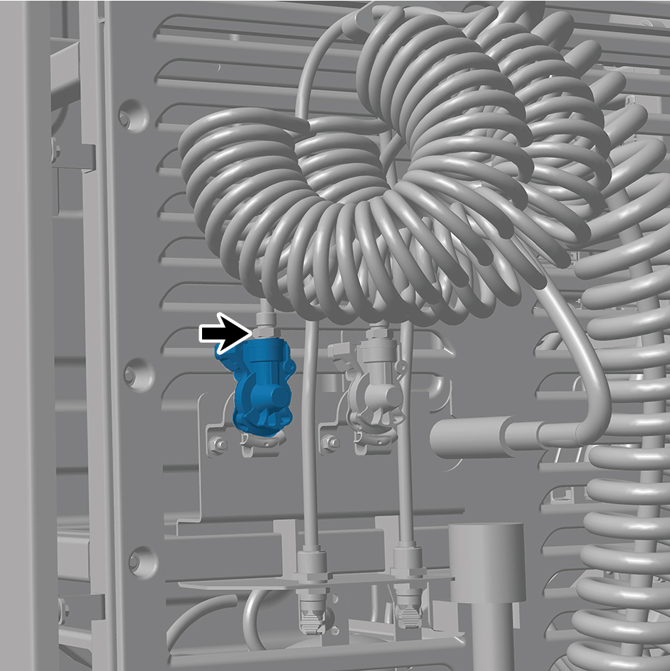
3
Remove the trailer connector assembly.
Installation Procedures
1
Move the trailer connector assembly to the mounting
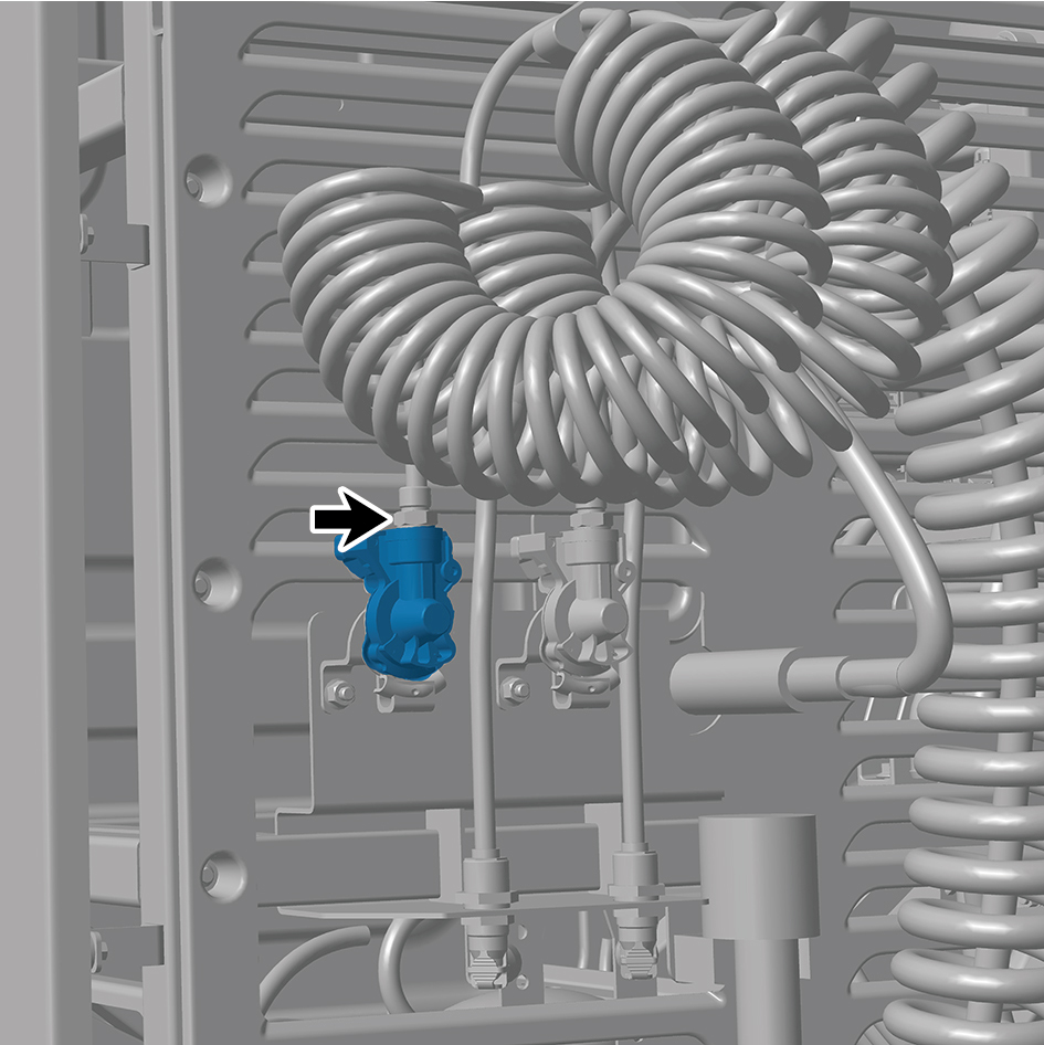
position.
2
Connect 1 air pipe of the trailer connector assembly.
8.15.3.8 Replacement of Trailer Connector Assembly (control)
Assembly (control)
Removal Procedures
1
Release air pressure from the brake system.
2
Disconnect 1 air pipe of the trailer connector assembly
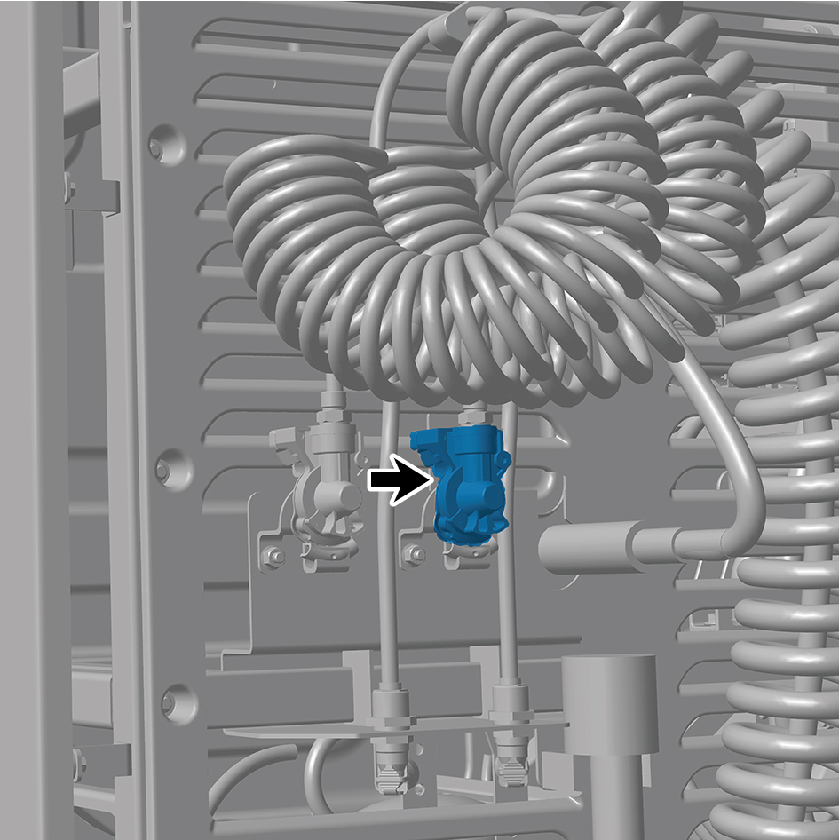
(control).
3
Remove the trailer connector assembly (control).
Installation Procedures
1
Move the trailer connector assembly (control) to the
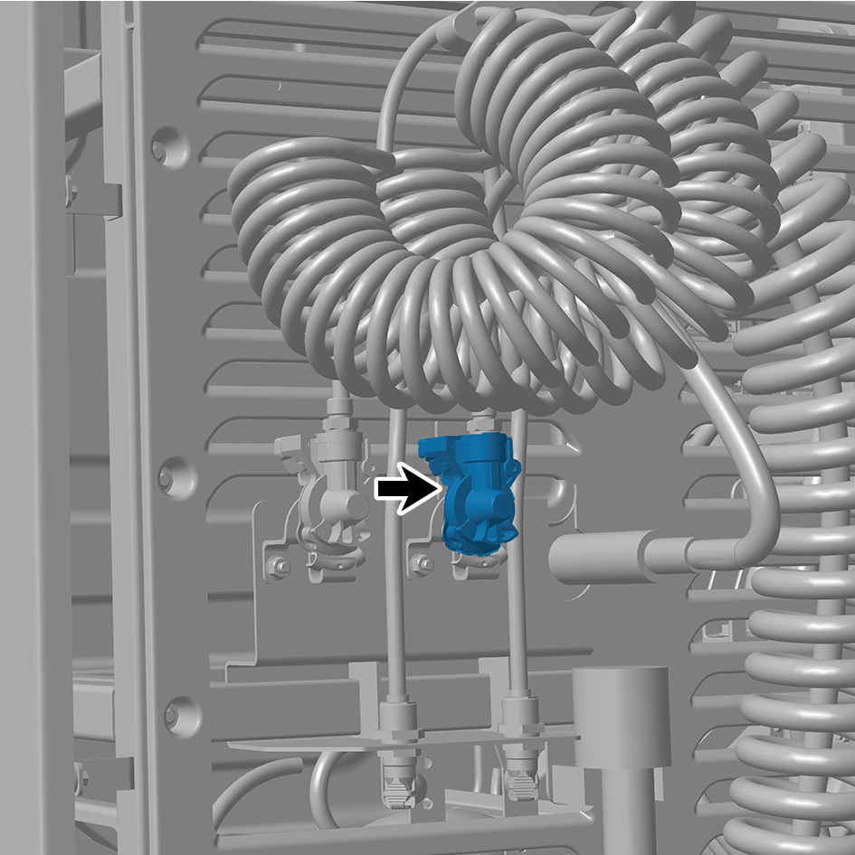
mounting position.
2
Connect 1 air pipe of the trailer connector assembly
(control).
8.15.3.9 Replacement of Dual Channel Module Assembly
Assembly
Removal Procedures
1
Release air pressure from the brake system.
2
Open the door.
3
Open the front flip cover plate.
4
Disconnect the battery negative cable.
caution
power down the high-voltage system before
disconnecting the negative pole of the storage
battery.
5
Disconnect 2 harness connectors of the dual channel
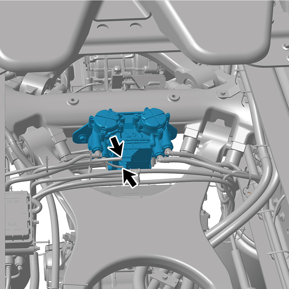
module assembly.
6
Disconnect 7 air pipes of the dual channel module
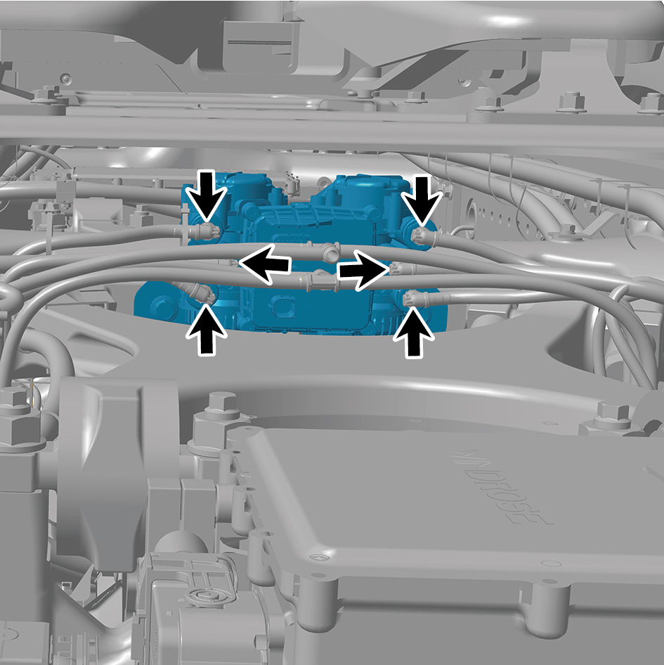
assembly.
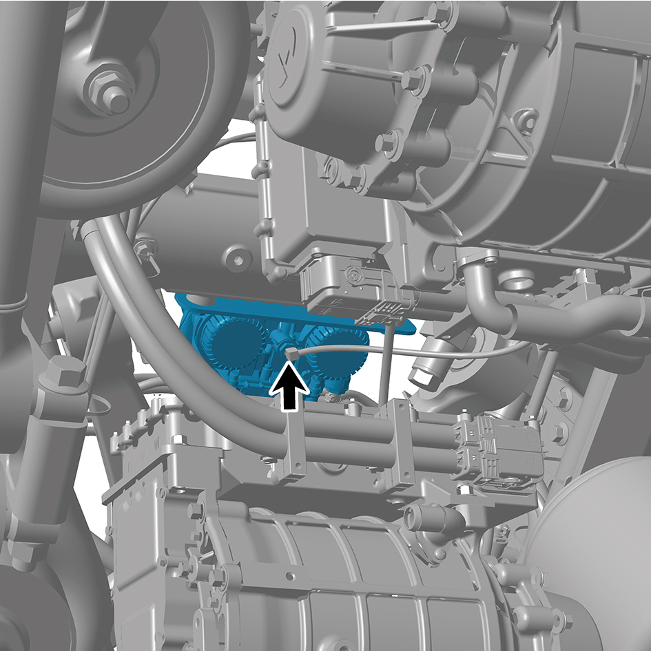
7
Remove 2 fixing bolts of the dual channel module
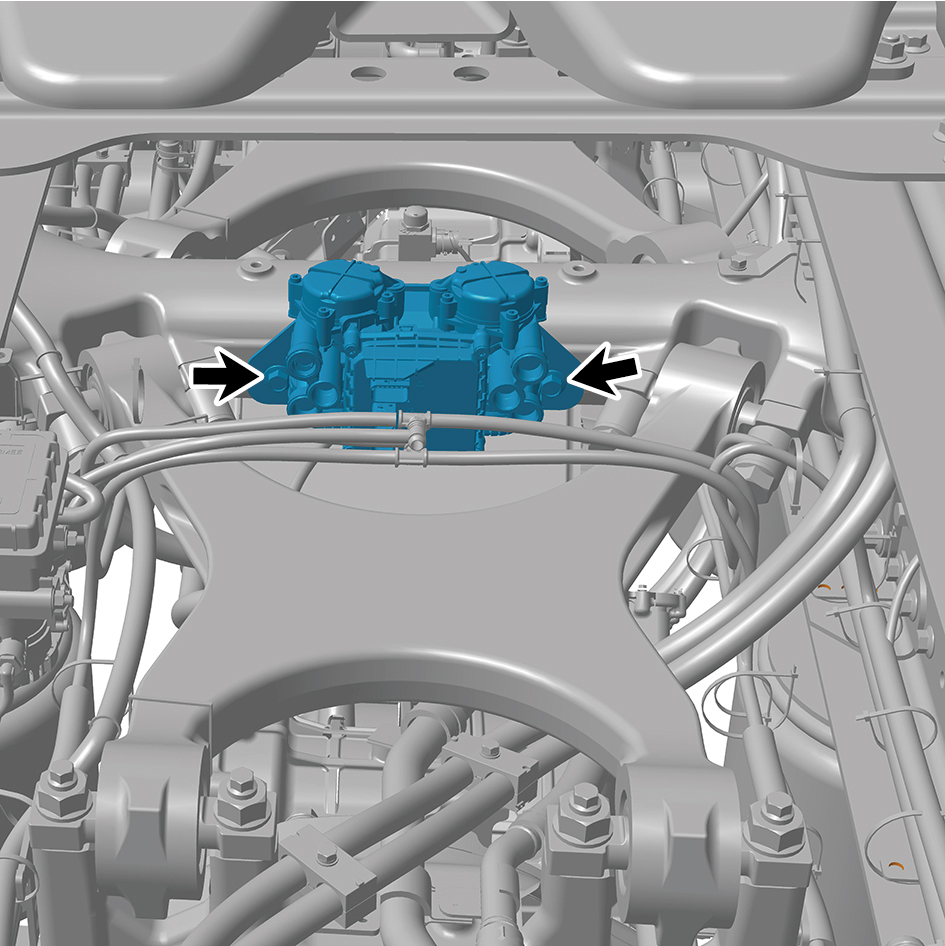
assembly.
8
Remove the dual channel module assembly.
Installation Procedures
1
Move the dual channel module assembly to the mounting
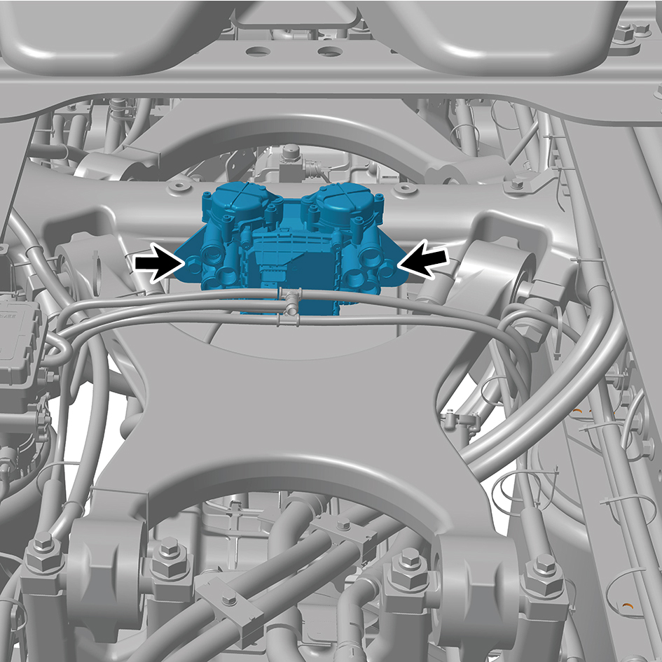
position.
2
Install 2 fixing bolts of the dual channel module assembly.
Torque: 70 +/- 3.5 (ft lbs)
3
Connect 7 air pipes of the dual channel module assembly.
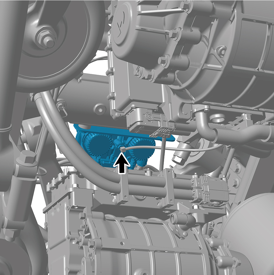
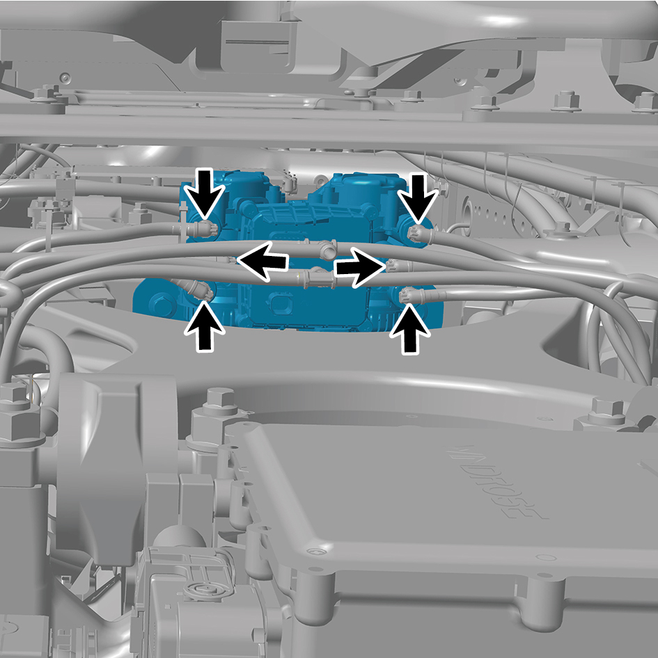
4
Connect 2 harness connectors of the dual channel
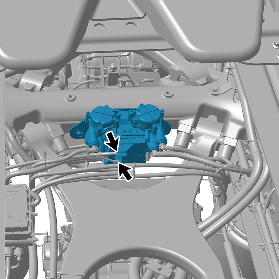
module assembly.
caution
The harness is firmly connected following the
principal of "insert until a click is heard for
confirmation".
5
Connect the battery negative cable.
6
Close the front flip cover plate.
7
Close the door.
8.15.3.10 Replacement of Low Pressure Alarm Switch
Switch
Removal Procedures
1
Open the door.
2
Open the front flip cover plate.
3
Disconnect the battery negative cable.
caution
power down the high-voltage system before
disconnecting the negative pole of the storage
battery.
4
Disconnect 1 harness connector of the low pressure
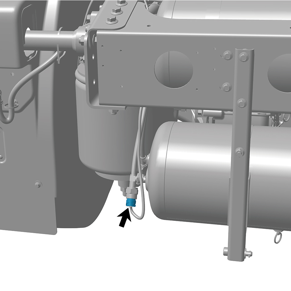
alarm switch.
5
Remove the low pressure alarm switch.
Installation Procedures
1
Move the low pressure alarm switch to the mounting
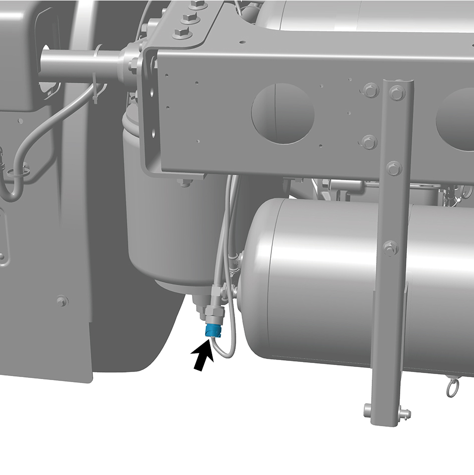
position.
2
Connect 1 harness connector of the low pressure alarm
switch.
caution
The harness is firmly connected following the
principal of "insert until a click is heard for
confirmation".
3
Connect the battery negative cable.
4
Close the front flip cover plate.
5
Close the door.
8.15.3.11 Replacement of Pressure Sensor
Removal Procedures
1
Open the door.
2
Open the front flip cover plate.
3
Disconnect the battery negative cable.
caution
power down the high-voltage system before
disconnecting the negative pole of the storage
battery.
4
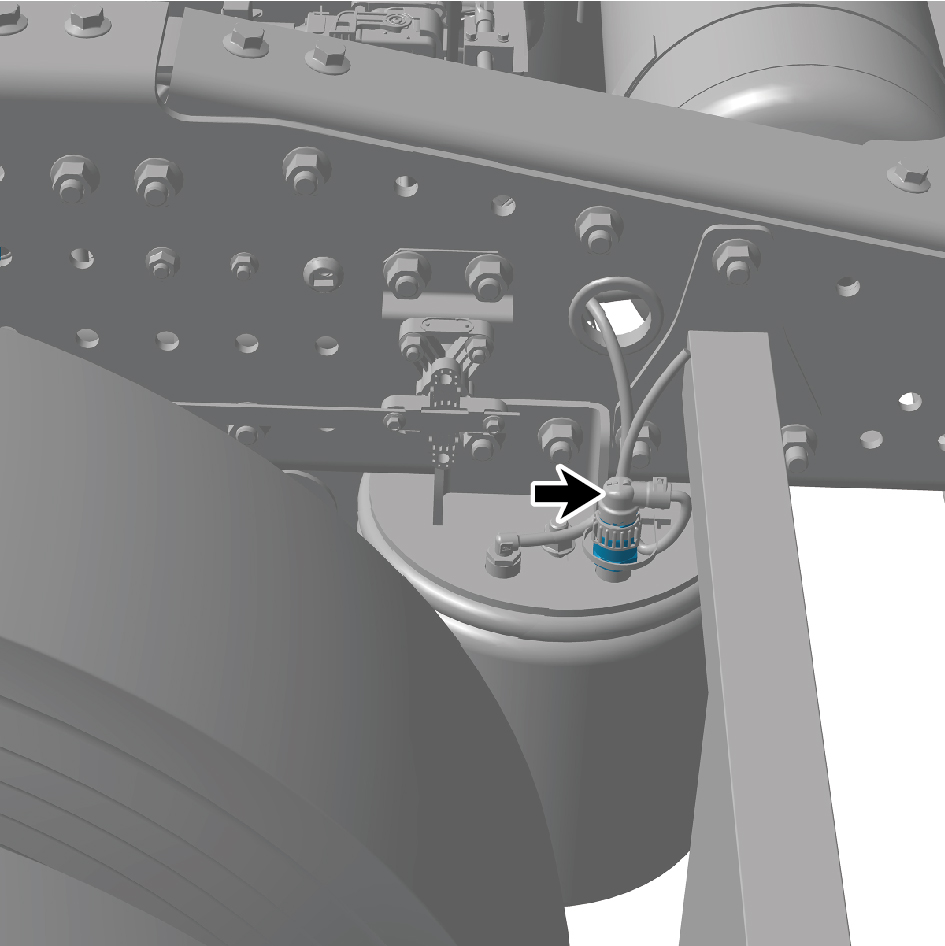
Disconnect 1 harness connector of the pressure sensor.
5
Remove the pressure sensor.
Installation Procedures
1
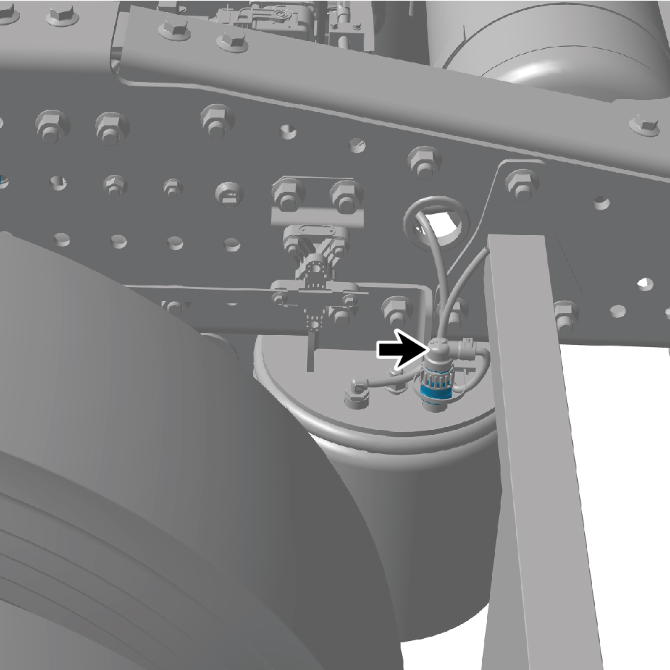
Move the pressure sensor to the mounting position.
2
Connect 1 harness connector of the pressure sensor.
caution
The harness is firmly connected following the
principal of "insert until a click is heard for
confirmation".
3
Connect the battery negative cable.
4
Close the front flip cover plate.
5
Close the door.