← Back to Contents
8 Chassis / 8.13 Steering Gear Device | PDF pages 2063-2092
8.13 Steering Gear Device
8.13 Steering Gear Device
8.13.1 Specifications
8.13.1.1 Fastener Specifications
Range Of Torque
Fastener Specifications
Specifications
Foot Pounds of Torque (ft lbs)
Fixed bolts connecting the integrated
406 +/- 14.75 (ft lbs)
M20
EHPS assembly to the frame on the
subframe
Fixed bolts connecting the integrated
39 +/- 5 (ft lbs)
M10
EHPS assembly to the steering column
The fixing nut connecting the electric oil
498 +/- 18.5 (ft lbs)
M45
pump and the active rocker arm
The joint connecting the electric oil
92 +/- 3.5 (ft lbs)
M26
pump and the oil inlet hose
The joint connecting the integrated
EHPS assembly to the high-pressure oil
55 +/- 3.5 (ft lbs)
M18
pipe
Fixing nut for high-pressure oil pipe
81 +/- 7.5 (ft lbs)
M22
Fixing nut for low-pressure oil pipe
81 +/- 7.5 (ft lbs)
M22
The fixing bolt connecting the electric oil
48 +/- 3.5 (ft lbs)
M12
pump and the electric oil pump bracket
The fixing bolts connecting the electric
48 +/- 3.5 (ft lbs)
oil pump bracket to the frame on the
M12
subframe
The fixing bolts connecting the electric
48 +/- 3.5 (ft lbs)
M12
oil pump to the frame on the subframe
The grounding wire fixing bolt
connecting the chassis harness and the
155 +/- 14.75 (ft lbs)
M14
frame assembly
The fixing bolt connecting the steering
18.5 +/- 2 (ft lbs)
M8
oil tank and the steering oil tank bracket
The fixing bolt connecting the steering
155 +/- 14.75 (ft lbs)
M14
oil pot bracket to the frame assembly
The fixing bolts connecting the frame
155 +/- 14.75 (ft lbs)
assembly and the electric oil pump
M14
bracket
The fixing bolts connecting the frame on
155 +/- 14.75 (ft lbs)
the subframe to the electric oil pump
M14
bracket
Range Of Torque
Fastener Specifications
Specifications
Foot Pounds of Torque (ft lbs)
The fixing bolt connecting the steering
oil pipe fixing clamp and the steering oil
6 +/- .75 (ft lbs)
M8
pipe fixing bracket 2
The fixing bolt connecting the electric oil
48 +/- 3.5 (ft lbs)
M12
pump to the chassis harness
The fixing bolt connecting the electric oil
48 +/- 3.5 (ft lbs)
M12
pump to the chassis harness bracket
8.13.1.2 Technical Parameters
Item
Parameter
Model of steering gear
34061X91
Manufacturer of steering gear
Shashi Jiulong Automotive Power Steering Gear Co., Ltd.
Steering gear type
Electro-hydraulic circulation ball type
Model of steering wheel
3402010X9D01
Diameter of steering wheel (mm)
380
Structure type of steering column
Mechanical adjustable type
Manufacturer of steering column
Yuyao Wanguo Machinery Co., Ltd.
Side angle of steering shaft α (°)
50
Plane angle of steering shaft β (°)
0
Steering boost type
Electric hydraulic power assistance
Manufacturer of steering booster
Shashi Jiulong Automotive Power Steering Gear Co., Ltd.
8.13.2 Decomposition Diagram
8.13.2.1 Decomposition Diagram
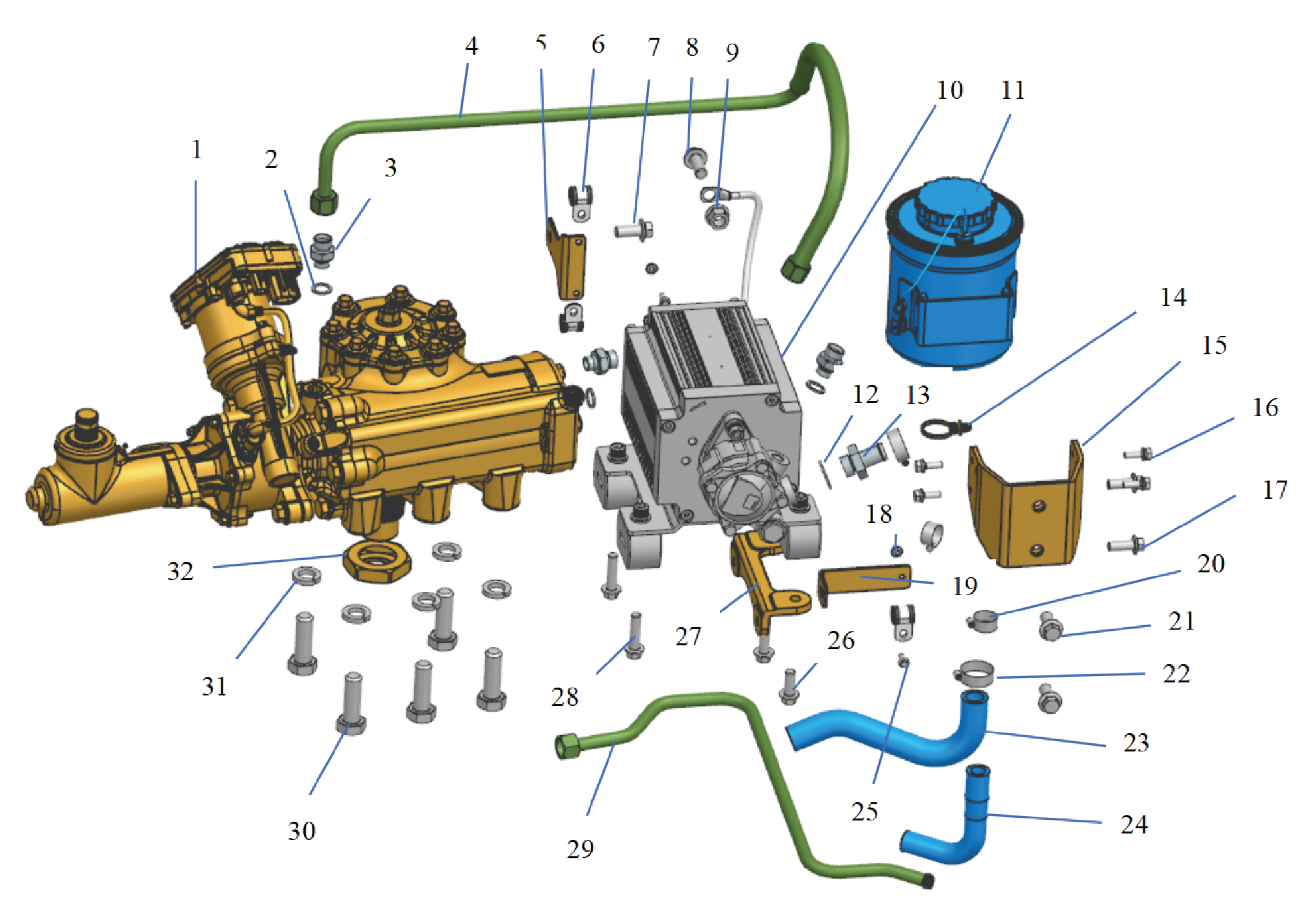
1.
17.
Hexagon Flange Bolt
Integrated EHPS Assembly
2.
18.
Hexagon Flange Nut
Sealing Gasket
3.
19.
Straight-Through Joint
Fixing Brkt-Steering Oil Pipe
4.
20.
High Pressure Tubing
Hose Hoop-Type B and Type c
5.
21.
Hexagon Flange Bolt
Steering Oil Pipe Fixing Bracket 2
6.
22.
Hose Hoop-Type B and Type c
Fixing Clip-Steering Oil Pipe
7.
23.
Hexagon Flange Bolt
Oil Inlet Hose
8.
Hexagon Flange Bolt
24.
Oil Return Hose
9.
Hexagon Flange Lock Nut_All Metal
25.
Hexagon Flange Bolt
10.
26.
Hexagon Flange Bolt
Electric Oil Pump
11.
27.
Oil Can
Electric Oil Pump bracket
12.
28.
Hexagon Flange Bolt
Oil Pump Inlet Tubing Connection
13.
29.
Low Pressure Tubing
Sealing Gasket
14.
Tie-Fir Tree
30.
Hexagon Bolt
15.
31.
Oil Pot Holder
Heavy Spring Washer
16.
32.
Assembly of Hexagon Head Bolt, Spring Washer and
Steering Gear Nut
Flat Washer In New Energy Vehicles
8.13.3 System Schematic Diagram
8.13.3.1 Electrical Schematic Diagram
8.13.4 Diagnostic Information and Steps
8.13.4.1 Diagnostic Description
Before diagnosing the malfunction of the steering gear device, it is important to understand and familiarize oneself with the
working principle of the steering gear device before starting the system diagnosis. This will help determine the correct fault
diagnosis steps when a malfunction occurs, and more importantly, it will help determine the situation described by the customer
belongs to normal operation. Any fault diagnosis of the steering gear device should start with routine inspection, guiding
maintenance personnel to take the next logical step for fault diagnosis. Understanding and correctly using the diagnostic process
can shorten the diagnosis time and avoid misjudgment of faulty parts.
8.13.4.2 Routine Inspection
• Check for aftermarket devices that may affect the operation of the steering system, ensuring that these devices do not affect the
operation of the steering system.
• Check system components that are easily accessible or visible to ensure that there is no obvious damage or potential
malfunction.
8.13.4.3 Fault Symptom Table
Symptom
Suspected Faulty Project
Measures
1. The steering column is deformed or
Check the appearance of the steering
stuck
column.
The steering wheel has no or little
Check for leaks in the transmission
2.Low transmission hydraulic oil level
power assistance
system oil pipes.
3.EHPS malfunction
Refer to EHPS Power Failure
8.13.4.4 DTC Confirmation
1. Connect the diagnostic tool to the diagnostic interface, read and record the DTC, and then clear the DTC.
2. Run the vehicle again.
3. Read the fault code of the control system again to confirm if there is any fault code output from the system.
– Yes:Diagnose based on the output fault code.
– No:Perform intermittent fault check, refer to Inspection Of Intermittent Faults
8.13.4.5 List Of Diagnostic Trouble Codes (DTC)
EHPS
Fault Description
Exclusion Method
Fault Code
High battery voltage
B111717
Low Battery Voltage
B111716
Supply voltage monitoring voltage too
C1EE54F
high (warning)
Refer to EHPS Power Fault
Supply voltage monitoring voltage too
C1EE651
low (warning)
The igition signal is lost
C1EF84C
Network CAN bus - communication
U007A88
failure
U012287
Lost communication with VDC
Refer to EHPS Communication Fault
VDC message is invalid
U143873
Lost communication with VDC_HSS1
U143587
Fault Description
Exclusion Method
Fault Code
Lost communication with VDC_HSS1
U143253
U015687
Lost communication with CDCU
CDCU message is invalid
U143353
U019887
Lost communication with TGW
TGW message is invalid
U143453
U015788
Lost communication with CAMF
U143553
CAMF function is invalid or incorrect
System entry thermal protection
C1EE75F
ECU overtemperature failure
C1EE15F
Temperature sensor failure
C1EE24C
ECU unexpected reset
C1EE3EC
ECU Hardware detection failure(Error
C1EE4EC
correction)
C1EF24C
ECU Internal electrical Faults
ECU internal power supply Faults
C1EE94C
ECU internal predrive faults
C1EE85C
Refer to EHPS Internal Fault
ECU internal magneto resistive chip
C1EE342
faults
ECU internal current detection loop
C1EE86C
faults
ECU internal motor three-phase current
C1EE88C
fault
Invaild Torque Sensor value
C1EE362
Abnormal Power Supply to the sensor
C1EF25F
Invaild Angle Sensor value
C1EF342
U14351F
CRC check is invalid
Steering wheel center position not
C1EE35F
Perform center calibration to set the
calibrated
steering gear to 0 position when the
EPS end protection is not learned
C1EE59F
vehicle is driving straight
EPS end protection is not learned
C1EE45F
8.13.4.6 EHPS Power Fault
1. DTC Monitoring Logic
Description
DTC Trigger Conditions
Faulty Part
DTC Code
1. Main battery
Supply voltage above limit and the duration of more
High battery voltage
B111717
2. Low voltage
than 1000ms
charging system
Supply voltage below limit and the duration of more
Low Battery Voltage
3. Wiring harness
B111716
than 1000ms
4.EHPS
Description
DTC Trigger Conditions
Faulty Part
DTC Code
Supply voltage
The power supply voltage is higher than the voltage
monitoring voltage too
C1EE54F
threshold . Enable power degradation.
high (warning)
Supply voltage
The power supply voltage is lower than the voltage
monitoring voltage too
C1EE651
threshold. Enable power degradatio
low (warning)
The engine is in the state of the operator. The controller
The igition signal is
cannot detect the ignition signal, and the controller
C1EF84C
lost
reports a failure after 20s.
2.Circuit Diagram
Smart Junction Box - Chassis
Battery
C6-2
C1-2
C1-1
KL15 Power supply 1 G01
EHPS Power supply
EHPS-KL30B G62a
-KL30A G62b
Power supply KL15 G01d
Power KL30 G62
C71-1
C72-2
EHPS
C71-3
C71-2
C72-1
Chassis CAN8-H TH08d
Chassis CAN8-L TL08d
Ground Z59
G08
Chassis CAN8
3. Diagnostic Steps
Step 1:DTC Confirmation. Refer to DTC Confirmation
Step 2:Routine Inspection. Refer to Routine Inspection
Step 3:Check if there are any other module power failure codes besides EHPS?
Check the main battery. Refer to Inspection Of The Main Battery
– Yes:
Check the low-voltage charging system. Refer to DCDC1 Low-voltage Charging System Fault
Next step
– No:
Step 4:Check the EHPS power supply and grounding harness.
Step 5:Rewrite configuration codes, reload software, and upgrade EHPS.
Step 6:Replace EHPS. Refer to Replacement Of Integrated EHPS Assembly
Step 7:Clear and confirm DTC.
8.13.4.7 EHPS Communication Fault
1. DTC Monitoring Logic
Description
DTC Trigger Conditions
Faulty Part
DTC Code
Network CAN bus -
8 consecutive busoffs without successful message
U007A88
transmission
communication failure
Continuous 500ms without receiving message VDC_
Lost communication
U012287
TCO1 (0x0CFE6CEE)
with VDC
If message VDC_TCO1 (0x0CFE6CEE) is not received
for 500ms continuously, any of the following situations
VDC message is
will occur for 10 consecutive frames:1. DLC is not equal
U143873
invalid
to 8; 2. The physical value exceeds the range of
0~155.999 mph
Continuous 1000ms without receiving message VDC_
Lost communication
U143587
HSS1 (0x18FCC231)
with VDC_HSS1
Any of the following situations occur in 10 consecutive
Lost communication
1. Wiring harness
frames of message VDC_HSS1 (0x18FCC231):1. DLC
U143253
with VDC_HSS1
2.EHPS
is not equal to 8; 2.When receiving a signal of 0x2 or
0x3
Continuous 5000ms without receiving message CDCU_
Lost communication
U015687
VDHR (0x18FEC1EEx)
with CDCU
The message CDCU_VDHR (0x18FEC1EEx) shows
any of the following situations for 10 consecutive
CDCU message is
U143353
frames:1. DLC is not equal to 8; 2. The physical value
invalid
exceeds the range of 0~99999995m
shows any of the following situations for 10 consecutive
frames:1. DLC is not equal to 8; 2. The physical value
Lost communication
exceeds the range of 0~99999995m and the message
U019887
with TGW
TGW_TD_Time (0x18FEE6EEx) has not been received
for 5000ms continuously
Description
DTC Trigger Conditions
Faulty Part
DTC Code
occur in 10 consecutive frames of message TGW-TD_
Time (0x18FEE6EEx):1. DLC is not equal to 8; 2. When
the physical value of TGW_Seconds signal exceeds 0-
59; 3. When the physical value of the TGW.Minute
signal exceeds 0-59; 4. When the physical value of the
TGW_Hours signal exceeds 0-23; 5. When the physical
TGW message is
value of the TGWlMench signal exceeds 1-12; 6. When
U143453
invalid
the physical value of the TGW-Day signal exceeds 1-31;
7. When the physical value of the TGW_Year signal
exceeds 1985-2235; 8.When the physical value of the
TGW_LocalMinuteOffset signal exceeds 0-59; 9.When
the physical value of the TGW_LocalHourOffset signal
exceeds If any of the following situations 0-59
Continuous 1000ms without receiving message
Lost communication
U015788
EHPSI1_LKA_CAMF (0x18FF0031x)
with CAMF
Message ADCU_SPSI1_LKA (0x18FF0031x) shows
any of the following situations for 10 consecutive
CAMF function is
frames:1. CRC does not comply with the algorithm; 2.
U143553
invalid or incorrect
The MC signal is discontinuous; 3. DLC is not equal to
8; 4. The EPS_VibAct signal value is 0x2-0x3
2.Circuit Diagram
Smart Junction Box - Chassis
Battery
C6-2
C1-2
C1-1
KL15 Power supply 1 G01
EHPS Power supply
EHPS-KL30B G62a
-KL30A G62b
Power supply KL15 G01d
Power KL30 G62
C71-1
C72-2
EHPS
C71-3
C71-2
C72-1
Chassis CAN8-H TH08d
Chassis CAN8-L TL08d
Ground Z59
G08
Chassis CAN8
3. Diagnostic Steps
Step 1:DTC Confirmation. Refer to DTC Confirmation
Step 2:Routine Inspection. Refer to Routine Inspection
Step 3:Check the CAN8 bus communication harness. Refer to Inspection of CAN8 bus network integrity
Step 4:Rewrite configuration codes, reload software, and upgrade EHPS.
Step 5:Replace EHPS. Refer to Replacement Of Integrated EHPS Assembly
Step 6:Clear and confirm DTC.
8.13.4.8 EHPS Internal Fault
1. DTC Monitoring Logic
Description
DTC Trigger Conditions
Faulty Part
DTC Code
The internal temperature of the controller or motor
System entry thermal
C1EE75F
exceeds the limit (standardised value)
protection
ECU overtemperature
ECU temperature exceeds normal range (T>257℉)
C1EE15F
failure
Temperature sensor
Abnormal voltage range of temperature sensor
C1EE24C
failure
ECU unexpected reset
C1EE3EC
MCU initialization reset error
ECU Hardware
detection failure(Error
C1EE4EC
MCU ECC Fault
correction)
ECU Internal electrical
1.MCU related faults
C1EF24C
Faults
2.The internal electrical fault occurs in the controller
ECU internal power
Internal power chip faults of the ECU
C1EE94C
supply Faults
ECU internal predrive
Internal predrive chip faults of the ECU
C1EE85C
1.EHPS
faults
ECU internal magneto
C1EE342
The reluctance sensor faults
resistive chip faults
ECU internal current
current detection loop fault
C1EE86C
detection loop faults
ECU internal motor
Motor three-phase current fault
C1EE88C
three-phase current
fault
Sensor torque signal out of range or abnormal
Invaild Torque Sensor
C1EE362
synchronization or torque signal sampling timeout
value
Abnormal Power
The power supply voltage of the sensor is beyond the
C1EF25F
Supply to the sensor
normal range
Angle sensor signal anomalies or angle signal
Invaild Angle Sensor
C1EF342
sampling timeout
value
Invalid SW flashed (Wrong layout Data Flash)
U14351F
CRC check is invalid
2. Diagnostic Steps
Step 1:DTC confirmation. Refer to DTC Confirmation
Step 2:Routine inspection. Refer to Routine Inspection
Step 3:Rewrite configuration codes, reload software, and upgrade EHPS.
Step 4:Replace EHPS. Refer to Replacement Of Integrated EHPS Assembly
Step 5:Clear and confirm DTC.
8.13.5 Dismantling and Installation
8.13.5.1 Replacement of Integrated EHPS Assembly
Assembly
Removal Procedures
1
Open the door.
2
Open the front flip cover plate.
3
Disconnect the battery negative cable.
4
Perform power-off of high voltage system.
5
Jack the front end of the vehicle.
6
Drain the transmission hydraulic oil.
7
Remove the guide wheel (right).
8
Remove the left front wheel housing rear body.
9
Remove the left side wall lower trim panel assembly.
10
Remove the side wall upper mounting bracket assembly
2.
11
Remove the left side wall mounting bracket 1.
12
Remove the left side wall mounting bracket 2.
13
Remove the left side wall lower trim panel mounting frame
assembly.
14
Remove the electric oil pump.
15
Remove the low pressure oil pipe.
16
Remove the high pressure oil pipe.
17
Remove the A/C compressor assembly.
18
Remove the driving rocker arm.
19
Disconnect 2 harness connectors of the integrated EHPS
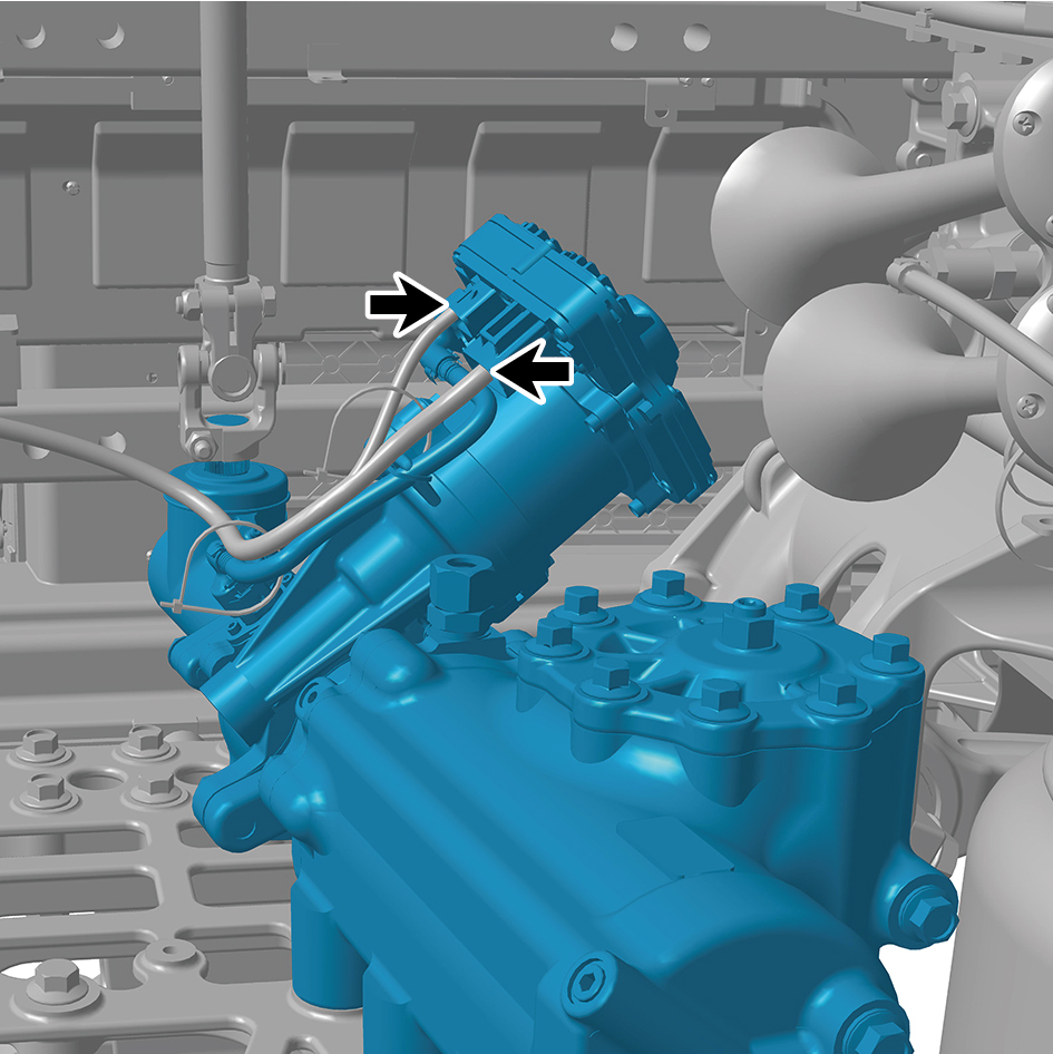
assembly.
20
Remove 1 fixing bolt connecting the integrated EHPS
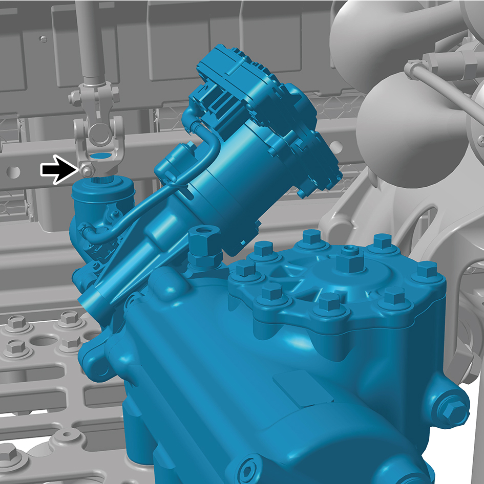
assembly to the steering drive shaft.
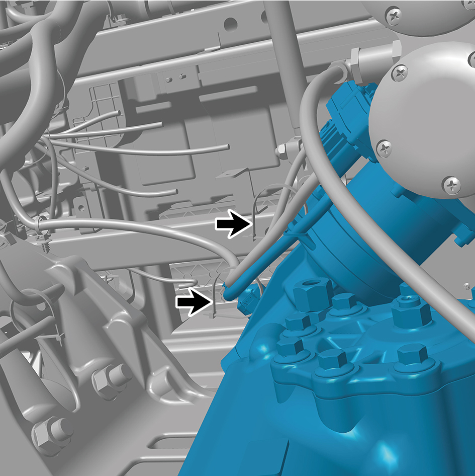
21
Remove 2 straps of the integrated EHPS assembly.
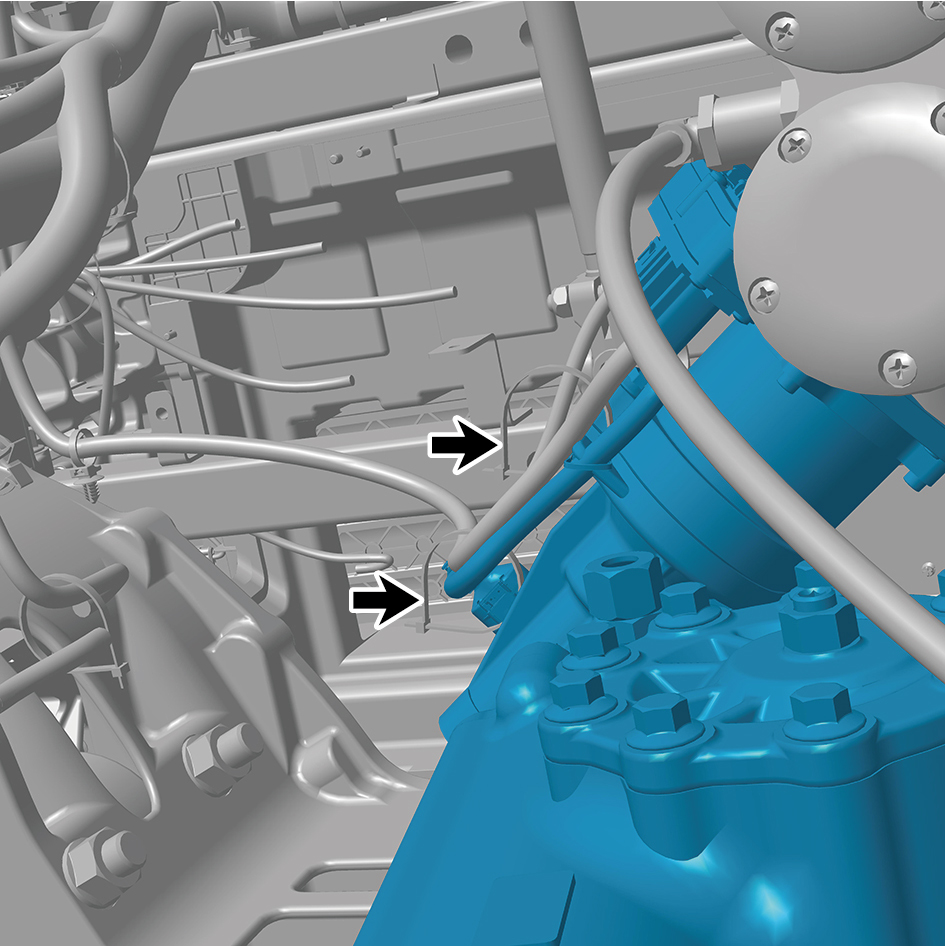
22
Remove 5 fixing bolts of the integrated EHPS assembly.
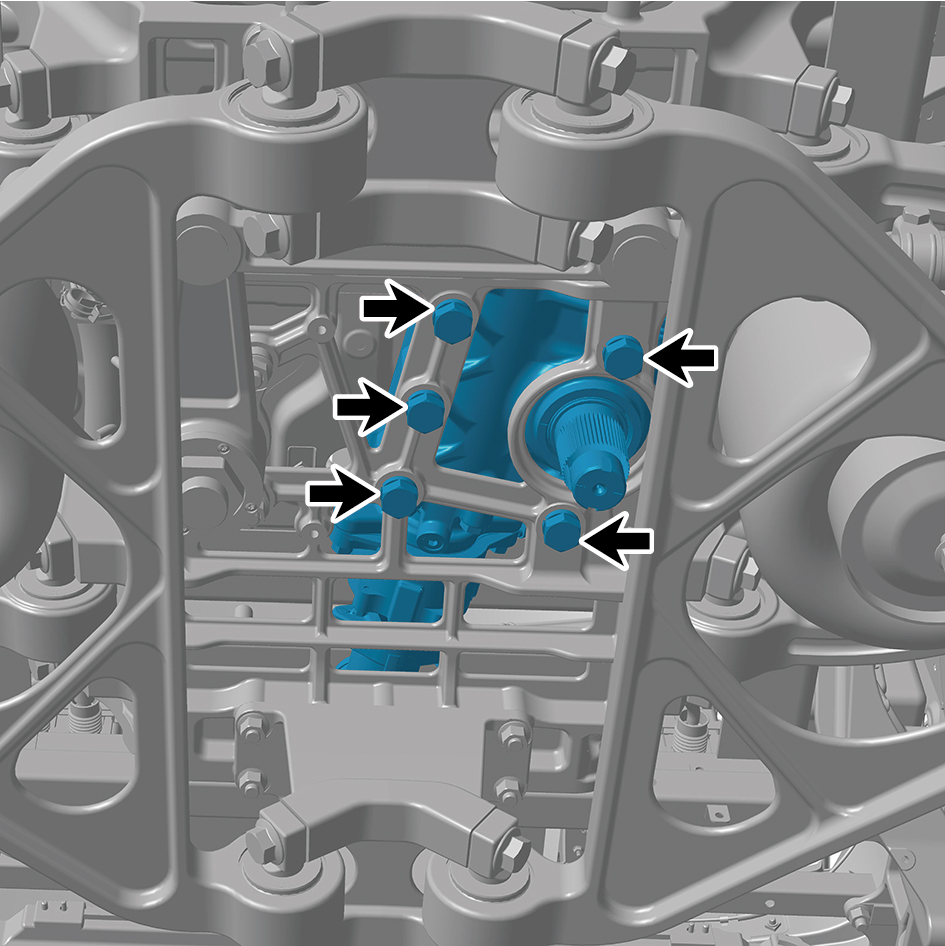
23
Remove the integrated EHPS assembly.
Installation Procedures
1
Move the integrated EHPS assembly to the mounting
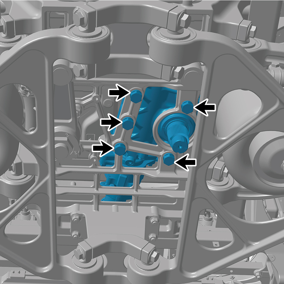
position.
2
Install 5 fixing bolts of the integrated EHPS assembly.
Torque: 442.5 +/- 37 (ft lbs)
3
Install 2 straps of the integrated EHPS assembly.
4
Install 1 fixing bolt connecting the integrated EHPS
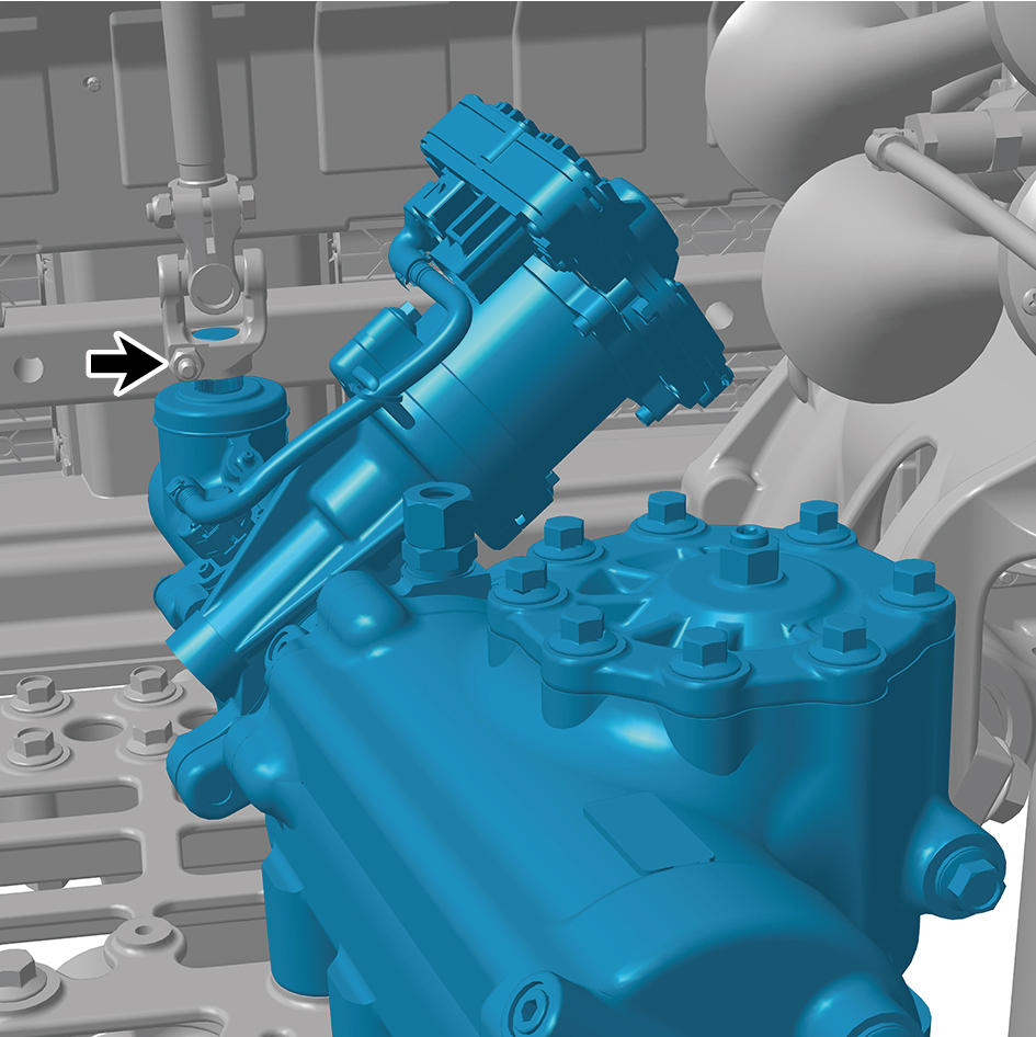
assembly to the steering drive shaft.
Torque:37 +/- 3.5 (ft lbs)
5
Connect 2 harness connectors of the integrated EHPS
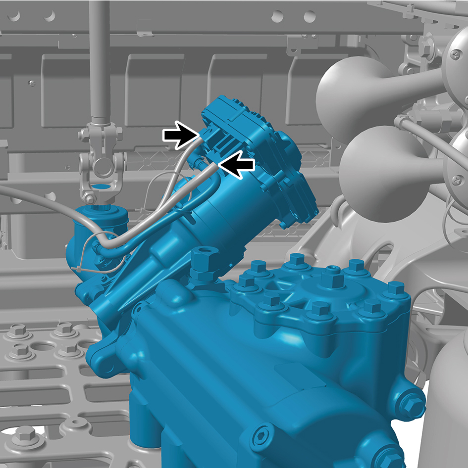
assembly.
caution
The harness is firmly connected following the
principal of "insert until a click is heard for
confirmation".
6
Install the driving rocker arm.
7
Install the A/C compressor assembly.
8
Install the high pressure oil pipe.
9
Install the low pressure oil pipe.
10
Install the electric oil pump.
11
Install the left side wall lower trim panel mounting frame
assembly.
12
Install the left side wall mounting bracket 2.
13
Install the left side wall mounting bracket 1.
14
Install the side wall upper mounting bracket assembly 2.
15
Install the left side wall lower trim panel assembly.
16
Install the left front wheel housing rear body.
17
Install the guide wheel (right).
18
Add the transmission hydraulic oil.
19
Lower the front end of the vehicle.
20
Perform power-on of the high voltage system.
21
Connect the battery negative cable.
22
Close the front flip cover plate.
23
Close the door.
caution
After part replacement, it is necessary to recalibrate
the zero position.
8.13.5.2 Replacement of Electric Oil Pump
Removal Procedures
1
Open the door.
2
Open the front flip cover plate.
3
Disconnect the battery negative cable.
4
Perform power-off of high voltage system.
5
Jack the front end of the vehicle.
6
Drain the transmission hydraulic oil.
7
Remove the left front wheel housing rear body.
8
Remove the left side wall lower trim panel assembly.
9
Remove the side wall upper mounting bracket assembly
2.
10
Remove the left side wall mounting bracket 1.
11
Remove the left side wall mounting bracket 2.
12
Remove the left side wall lower trim panel mounting frame
assembly.
13
Disconnect 1 high voltage harness connector of the
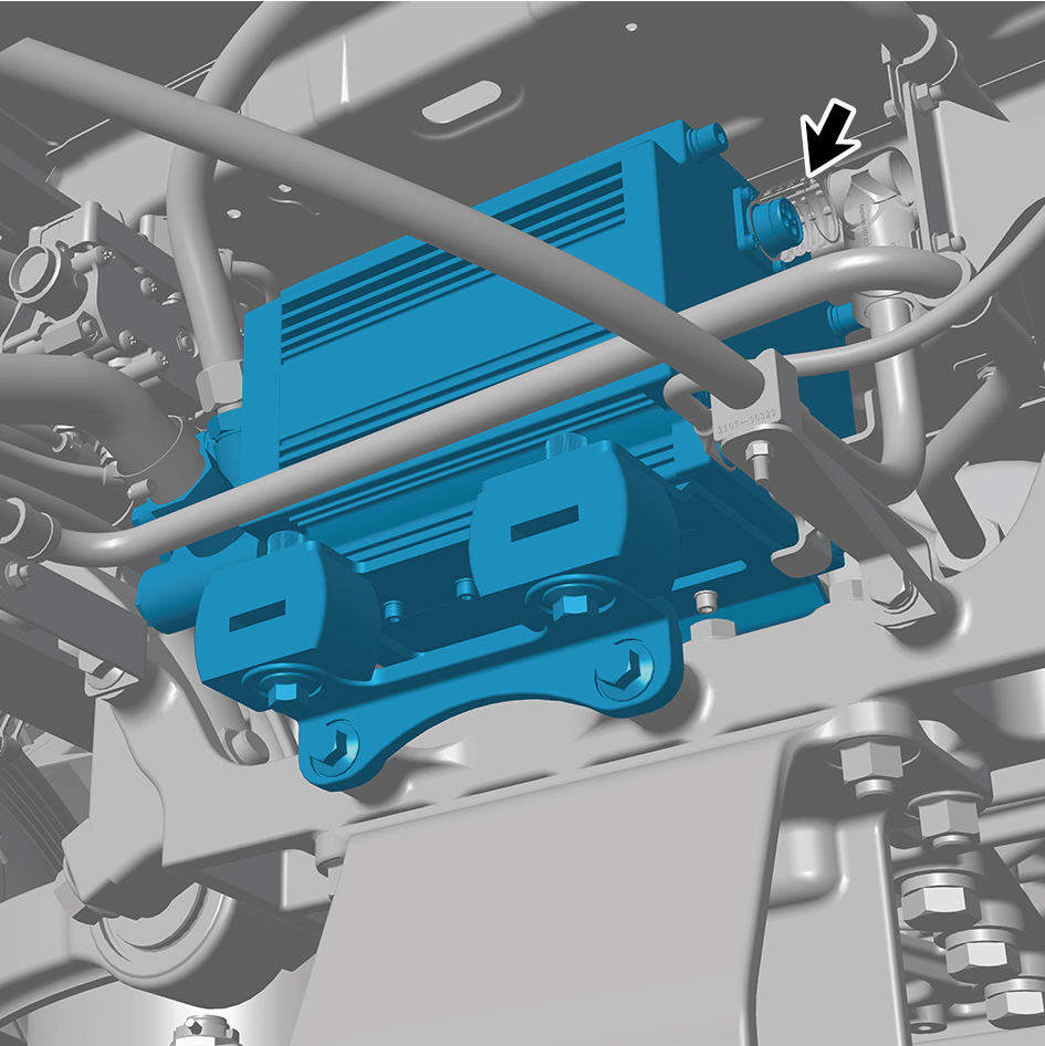
electric oil pump.
14
Disconnect 2 pipelines of the electric oil pump.
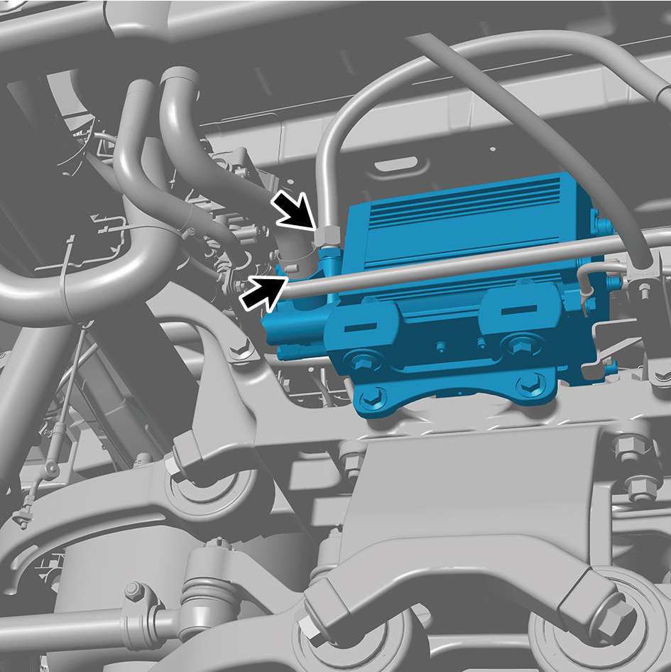
caution
All disconnected oil pipe joints shall be sealed to
prevent the entry of debris and residual oil from
flowing out.
15
Remove 2 fixing bolts of the harness accessory.
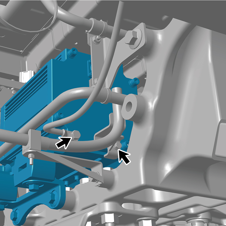
16
Remove 4 fixing bolts of the electric oil pump, and remove
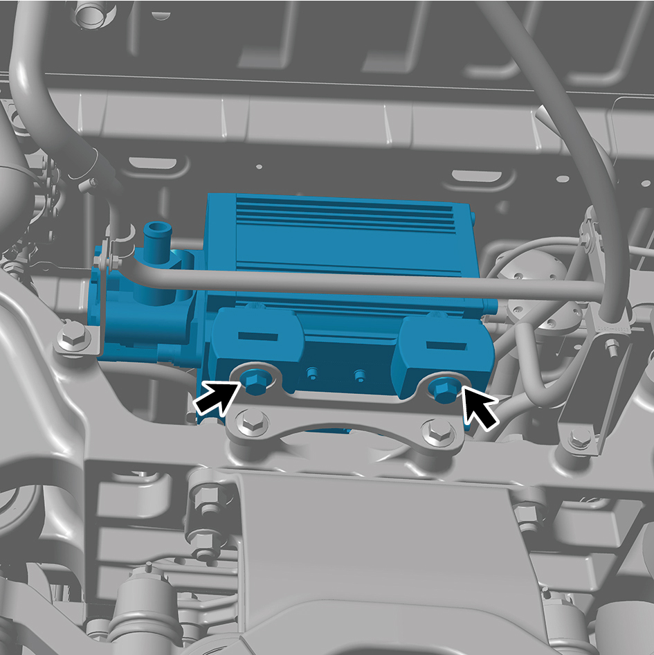
the electric oil pump.
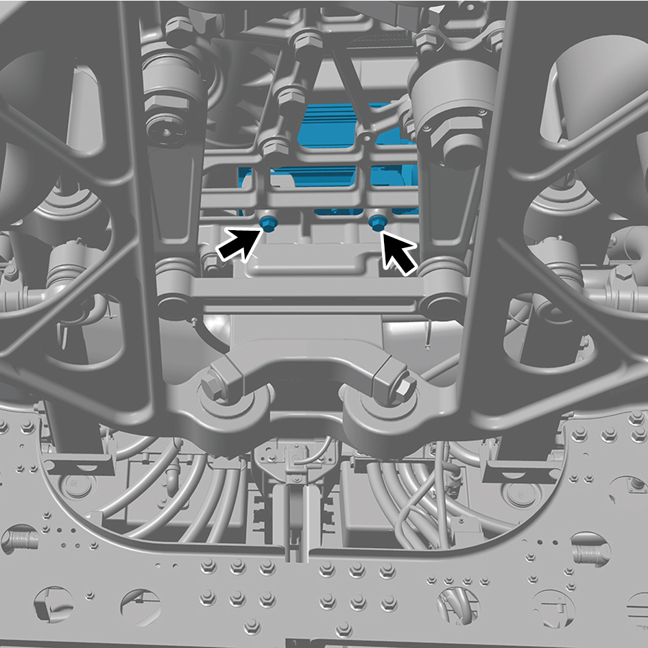
Installation Procedures
1
Move the electric oil pump to the mounting position.
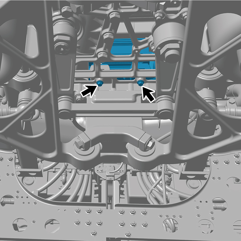
2
Install 4 fixing bolts of the electric oil pump.
Torque: 44 +/- 3.5 (ft lbs)

3
Install 2 fixing bolts of the harness accessory.
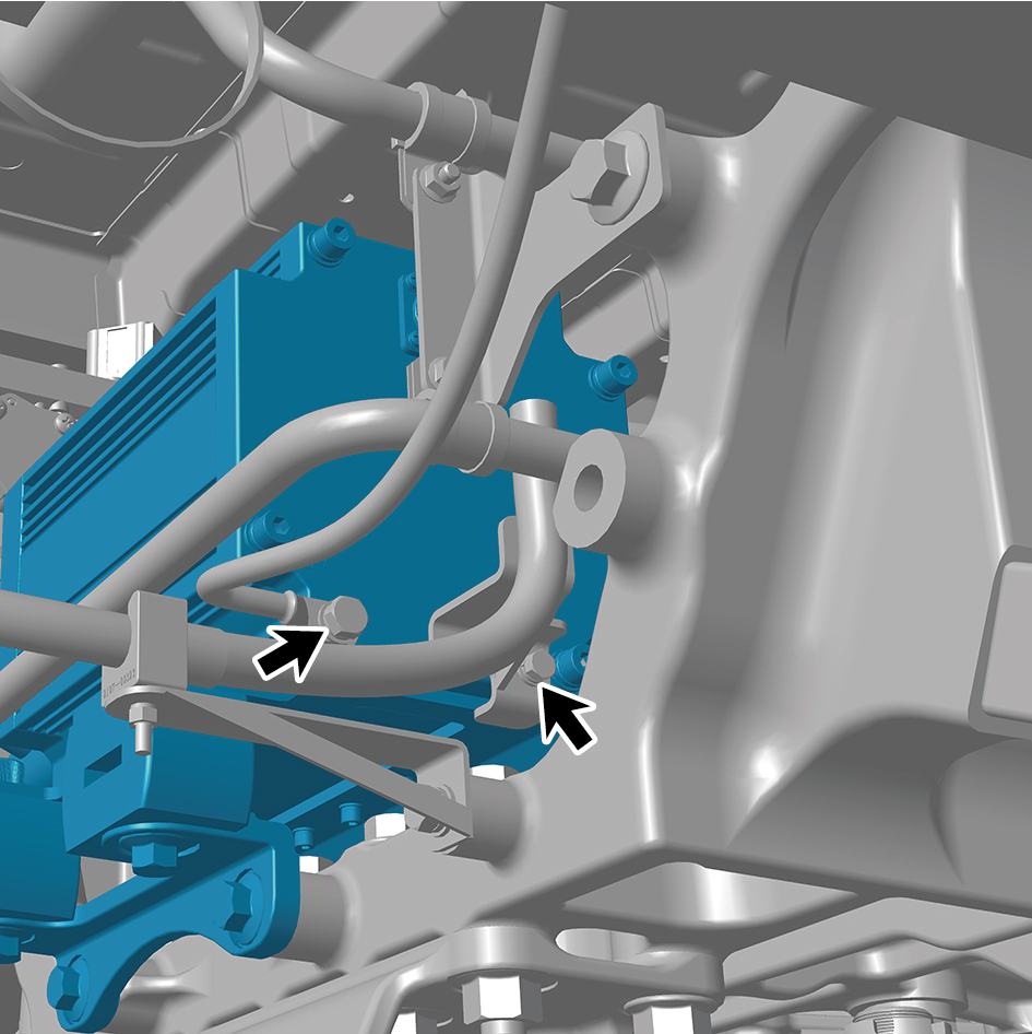
Torque: 44 +/- 3.5 (ft lbs)
4
Connect 2 pipelines of the electric oil pump.
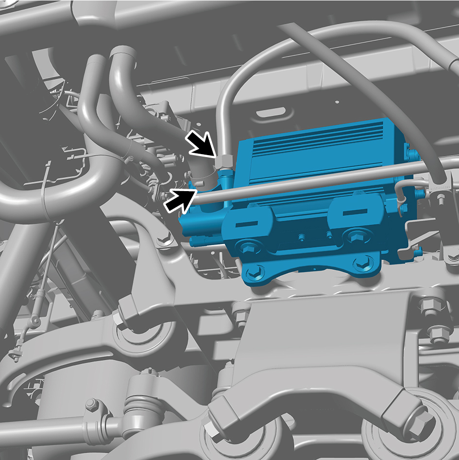
5
Connect 1 high voltage harness connector of the electric
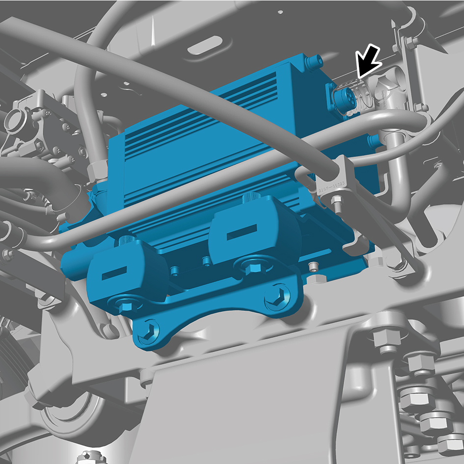
oil pump.
caution
The harness is firmly connected following the
principal of "insert until a click is heard for
confirmation".
6
Install the left side wall lower trim panel mounting frame
assembly.
7
Install the left side wall mounting bracket 2.
8
Install the left side wall mounting bracket 1.
9
Install the side wall upper mounting bracket assembly 2.
10
Install the left side wall lower trim panel assembly.
11
Install the left front wheel housing rear body.
12
Add the transmission hydraulic oil.
13
Lower the front end of the vehicle.
14
Perform power-on of the high voltage system.
15
Connect the battery negative cable.
16
Close the front flip cover plate.
17
Close the door.
8.13.5.3 Replacement of Steering Fluid Reservoir
Reservoir
Removal Procedures
1
Open the door.
2
Open the front flip cover plate.
3
Disconnect the battery negative cable.
caution
power down the high-voltage system before
disconnecting the negative pole of the storage
battery.
4
Jack the front end of the vehicle.
5
Drain the transmission hydraulic oil.
6
Remove the steering fluid reservoir assembly.
7
Disconnect 1 harness connector of the steering fluid
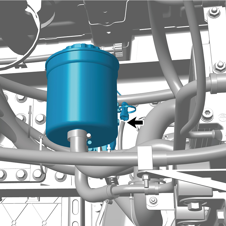
reservoir.
8
Disconnect 2 pipelines of the steering fluid reservoir.
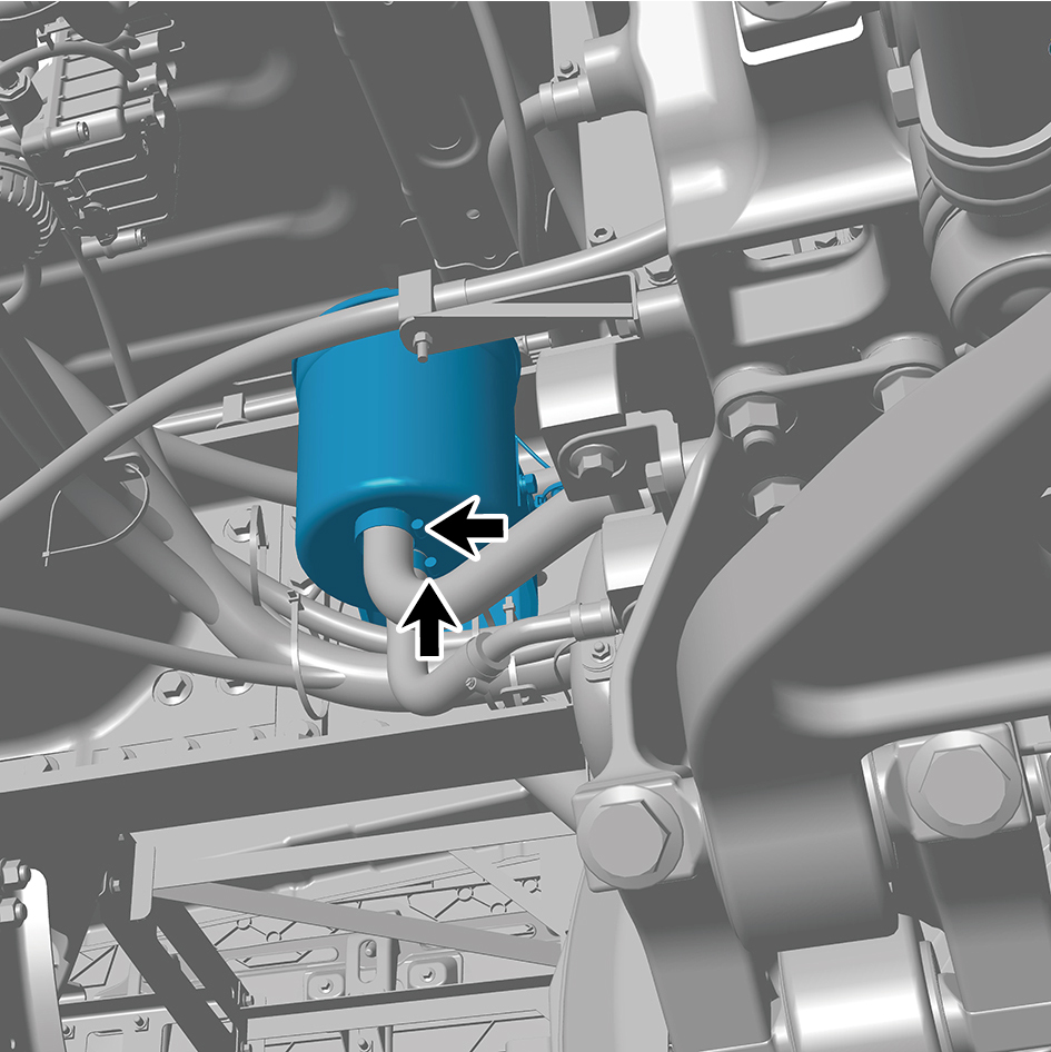
caution
All disconnected oil pipe joints shall be sealed to
prevent the entry of debris and residual oil from
flowing out.
9
Remove 2 fixing bolts and nuts of the steering fluid
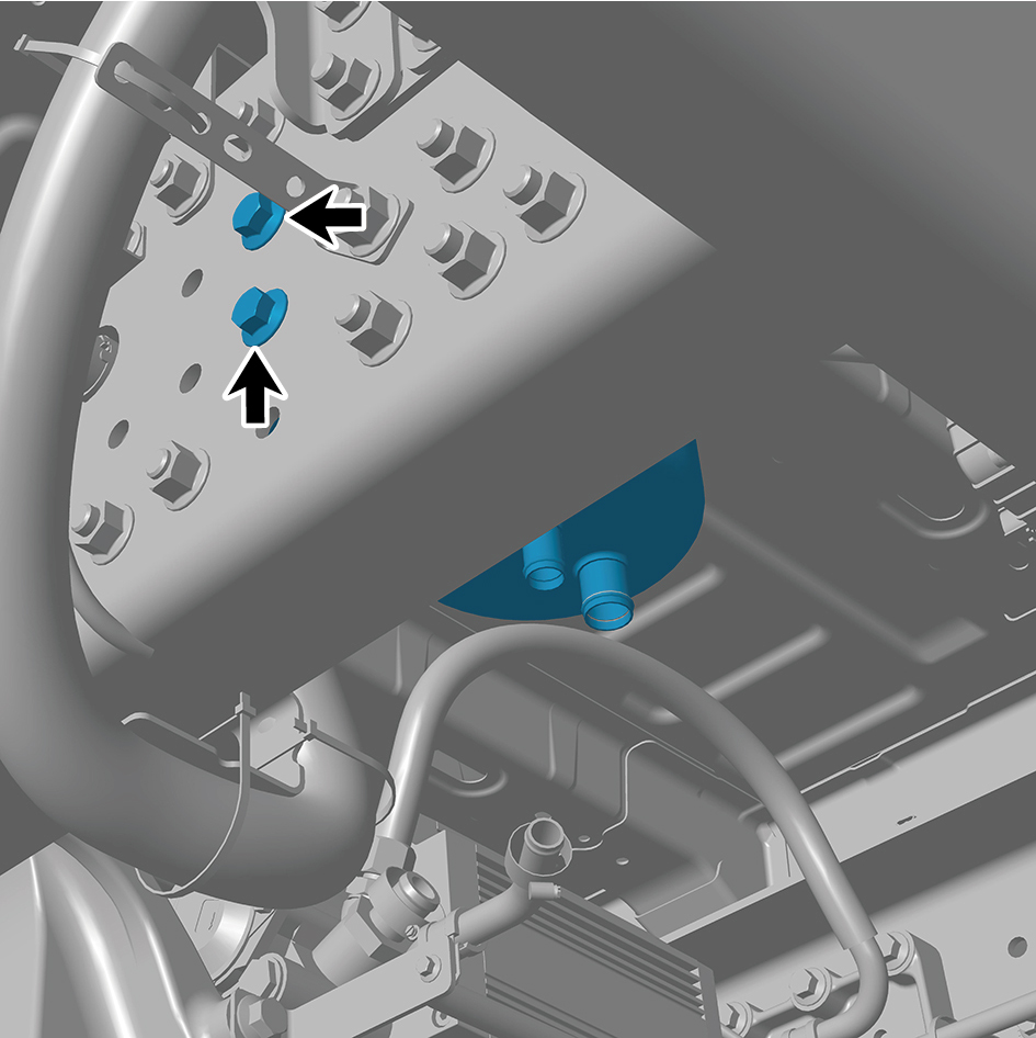
reservoir, and remove the steering fluid reservoir with
bracket.
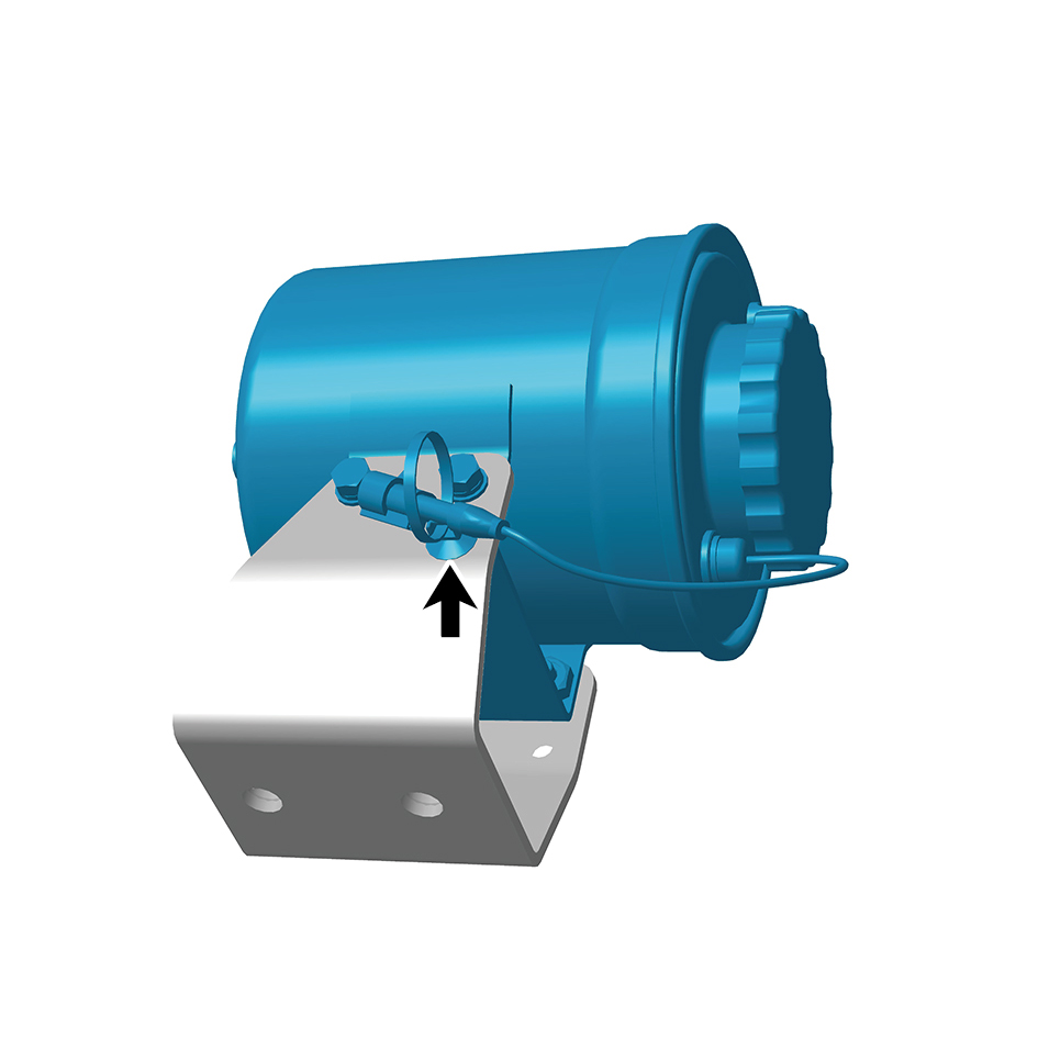
10
Disengage 1 fixing clip of the steering fluid reservoir.
11
Remove 4 fixing bolts and nuts connecting the steering
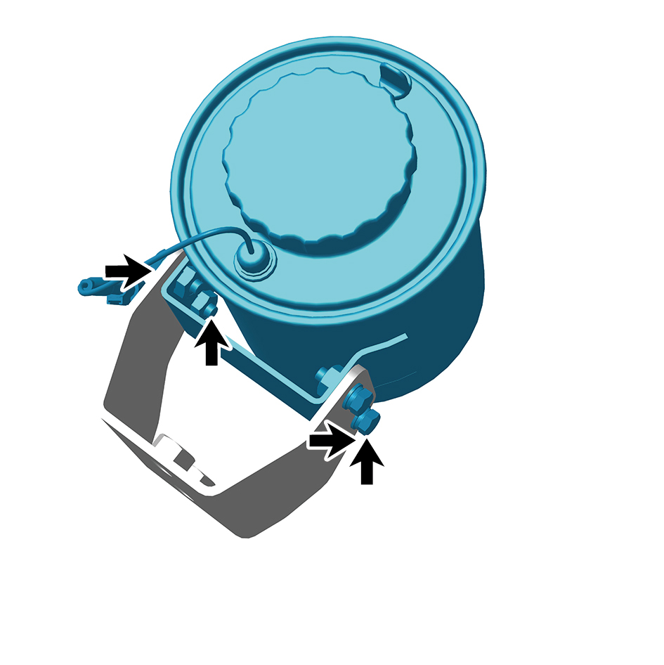
fluid reservoir to the steering fluid reservoir bracket.
12
Remove the steering fluid reservoir.
Installation Procedures
1
Move the steering fluid reservoir to the mounting position.
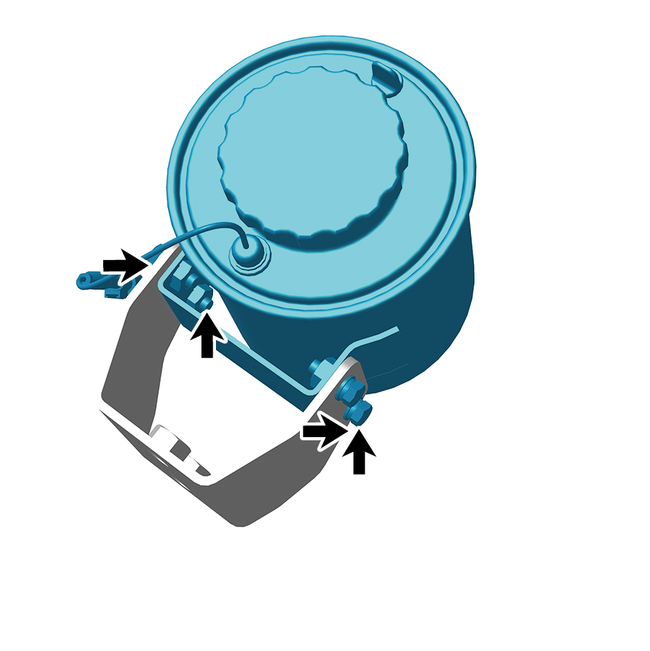
2
Install 4 fixing bolts and nuts connecting the steering fluid
reservoir to the steering fluid reservoir bracket.
Torque: 18.5 +/- 2 (ft lbs)
3
Install 1 fixing clip of the steering fluid reservoir.
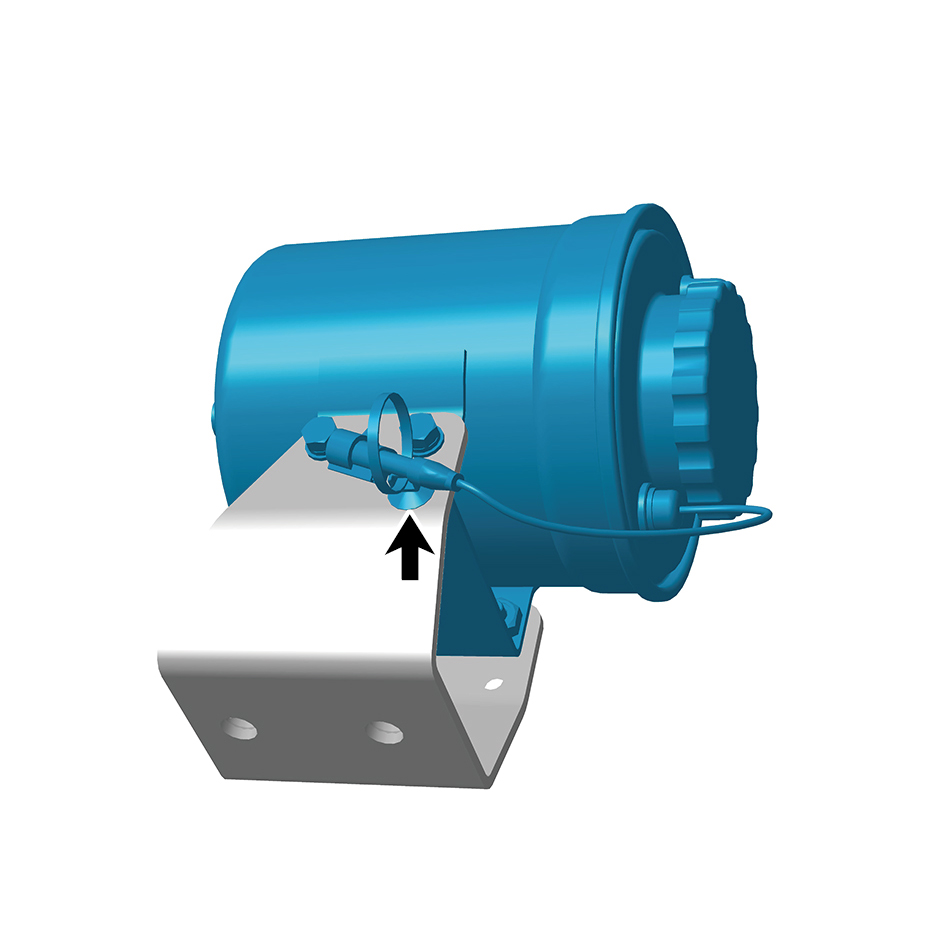
4
Install 2 fixing bolts and nuts of the steering fluid reservoir
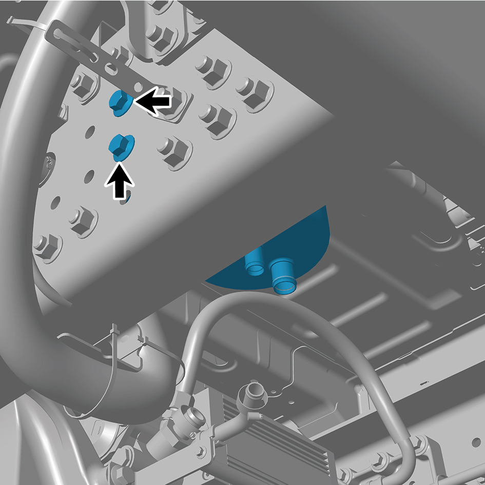
with bracket.
Torque: 155 +/- 14.75 (ft lbs)
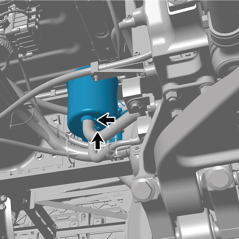
5
Connect 2 pipelines of the steering fluid reservoir.
6
Connect 1 harness connector of the steering fluid
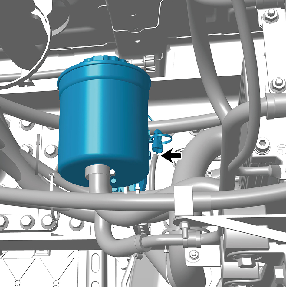
reservoir.
caution
The harness is firmly connected following the
principal of "insert until a click is heard for
confirmation".
7
Install the steering fluid reservoir assembly.
8
Add the transmission hydraulic oil.
9
Lower the front end of the vehicle.
10
Connect the battery negative cable.
11
Close the front flip cover plate.
12
Close the door.
8.13.5.4 Replacement of Transmission Hydraulic Oil
Hydraulic Oil
Removal Procedures
1
Jack the front end of the vehicle.
2
Remove the transmission hydraulic oil filter element.
3
Disconnect the oil inlet hose.
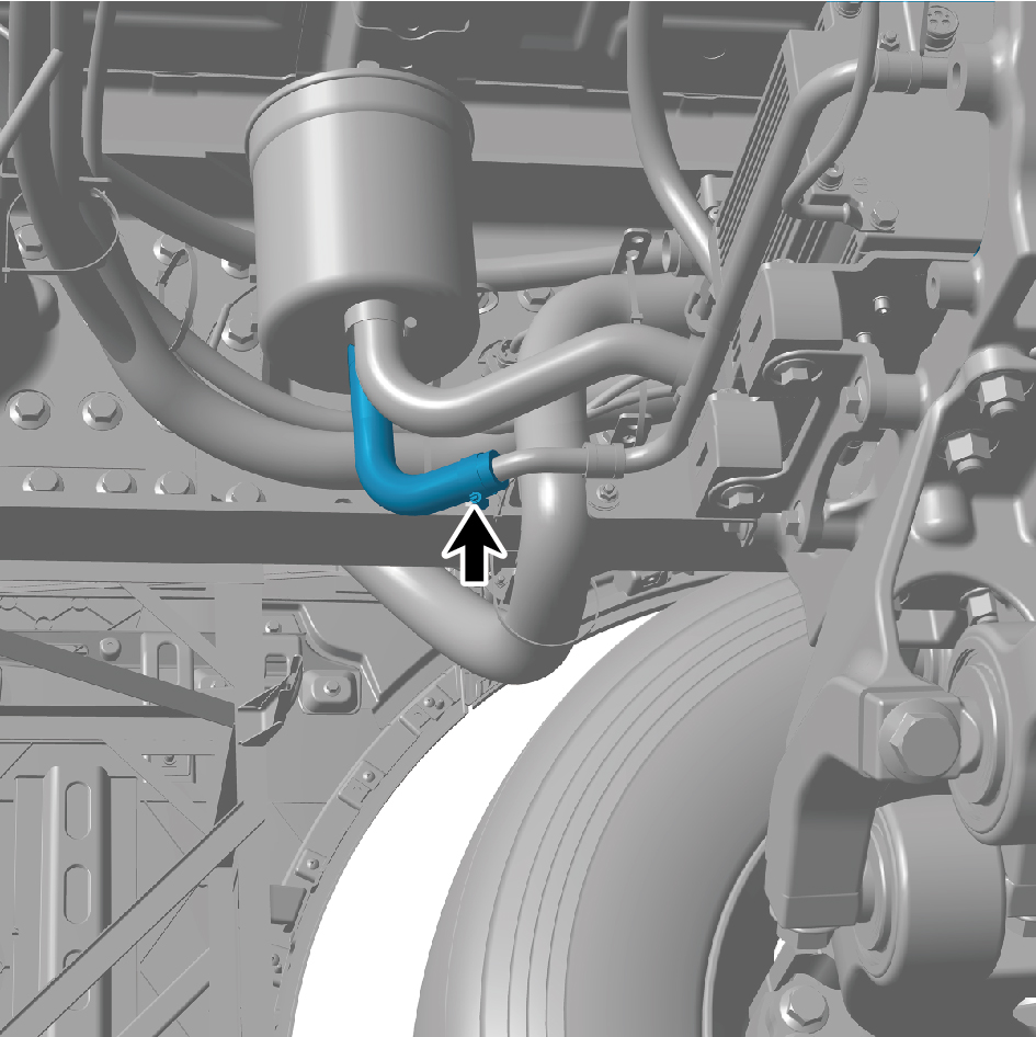
4
Drain the transmission hydraulic oil.
Installation Procedures
1
Connect the oil inlet hose.
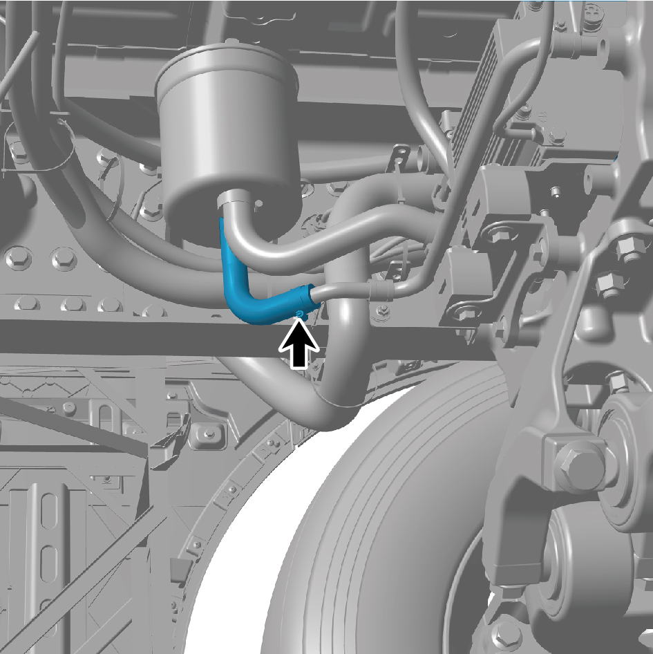
2
Add the transmission hydraulic oil.
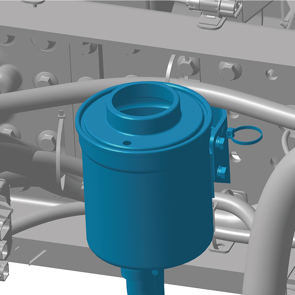
3
Turn the steering wheel several times between the
extreme positions on the left and right sides until the
steering fluid level in the steering fluid reservoir no longer
drops and no bubbles are generated.
caution
The steering wheel shall not stay in the extreme
position for more than 5 seconds to avoid damaging
the steering gear.
4
Check the steering hydraulic oil level.
caution
It is normal for the oil level to exceed the upper limit
scale by 1-2mm.
5
Install the transmission hydraulic oil filter element.
6
Lower the front end of the vehicle.
8.13.5.5 Replacement of Transmission Hydraulic Oil Filter Element
Hydraulic Oil Filter Element
Removal Procedures
1
Jack the front end of the vehicle.
2
Remove the filler cap.
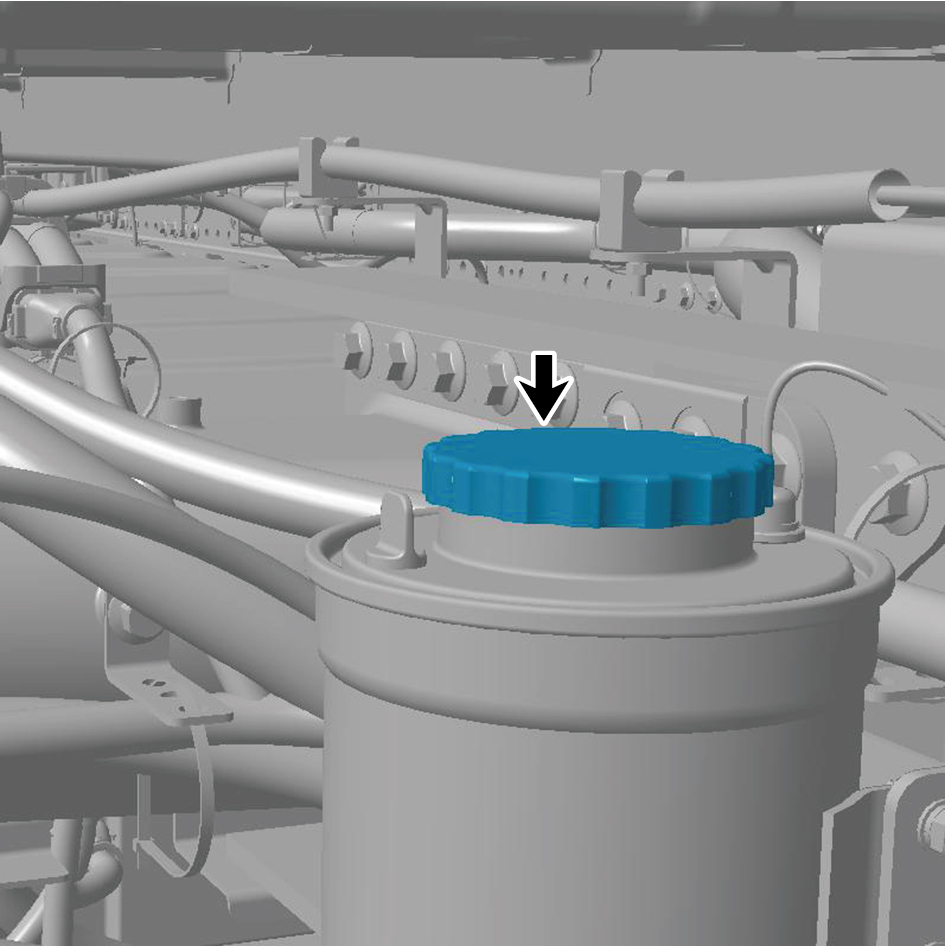
3
Remove the transmission hydraulic oil filter element.
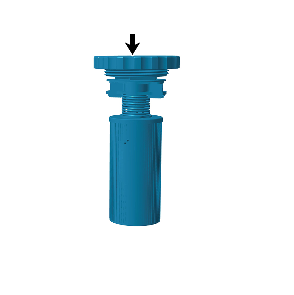
Installation Procedures
1
Install the transmission hydraulic oil filter element.
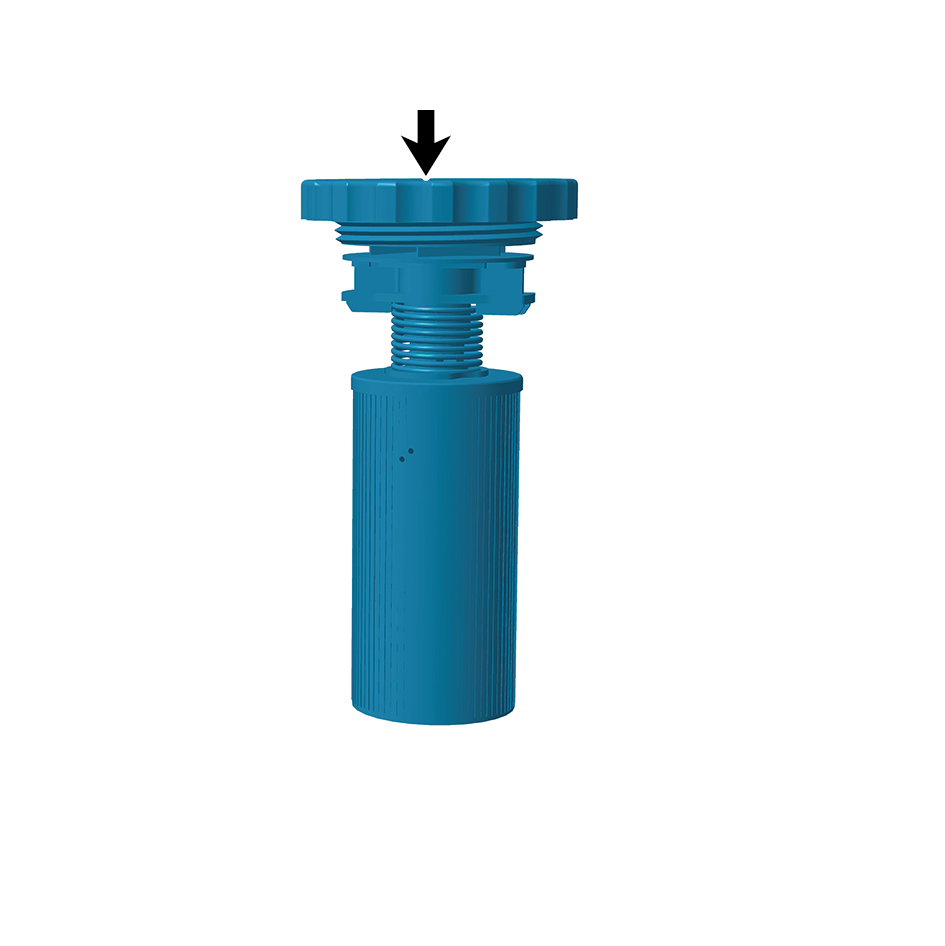
2
Install the filler cap.
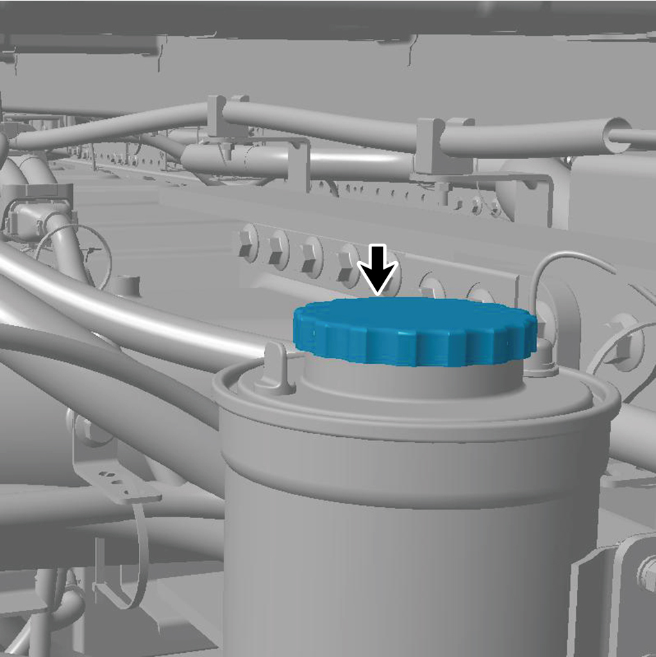
3
Lower the vehicle.