← Back to Contents
8 Chassis / 8.12 Steering Control Device | PDF pages 2055-2062
8.12 Steering Control Device
8.12 Steering Control Device
8.12.1 Specifications
8.12.1.1 Fastener Specifications
Range Of Torque
Fastener Specifications
Specifications
Foot Pounds of Torque (ft lbs)
The fixing bolts connecting the steering
column assembly and the steering
26 +/- 3.5 (ft lbs)
M10
column fixing bracket
The fixing bolts connecting the steering
column assembly and the pipe beam
18.5 +/- 2 (ft lbs)
M8
assembly
The fixing bolts connecting the steering
column assembly and the integrated
39 +/- 5 (ft lbs)
M10
EHPS assembly
Cross joint of steering column assembly
39 +/- 5 (ft lbs)
M10
- fixing bolt for steering gear
Cross joint of steering column assembly
39 +/- 5 (ft lbs)
M10
- fixing nut for steering gear
The fixing nut connecting the steering
column assembly and the steering
44 +/- 3.5 (ft lbs)
M14
wheel assembly
8.12.2 Decomposition Diagram
8.12.2.1 Decomposition Diagram
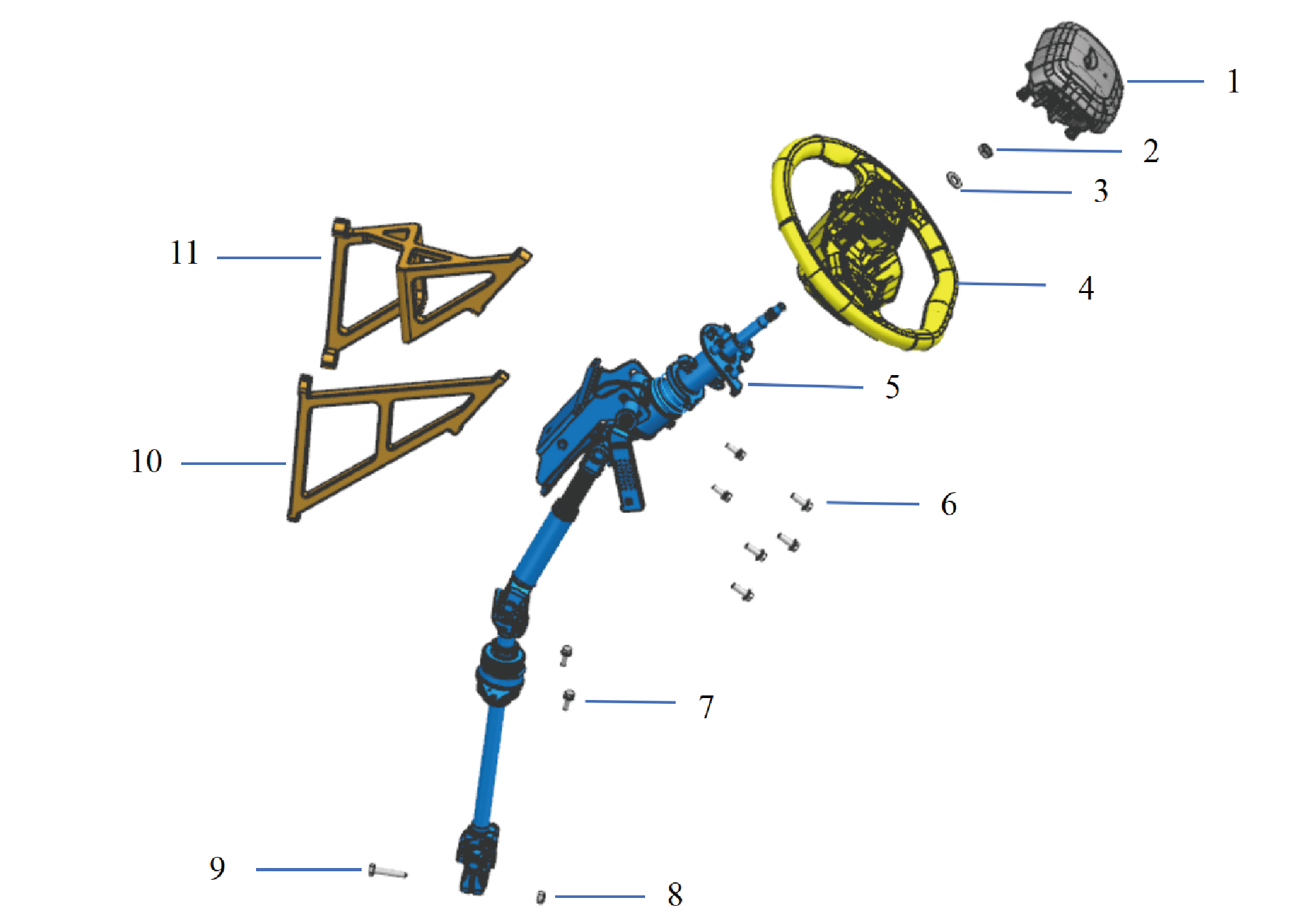
7.
1.
Hexagon Head Bolt Assy
Dab Decorative Cove
2.
Hex Thin Nut
8.
Hexagon Flange Lock Nut_All Metal
3.
Flat Washer
9.
Hexagon Bolt
4.
10.
Steering Wheel Assy
Fixing Bracket of Steering Column 1
5.
11.
Steering Column Assy
Fixing Bracket of Steering Column 2
6.
Hexagon Flange Bolt
8.12.3 Dismantling and Installation
8.12.3.1 Replacement of Steering Wheel Assembly
Assembly
Removal Procedures
1
Open the door.
2
Open the front flip cover plate.
3
Disconnect the battery negative cable.
caution
power down the high-voltage system before
disconnecting the negative pole of the storage
battery.
4
Remove the combination switch lower shield.
5
Remove the driver horn cover assembly.
6
Disconnect 1 harness connector of the steering wheel
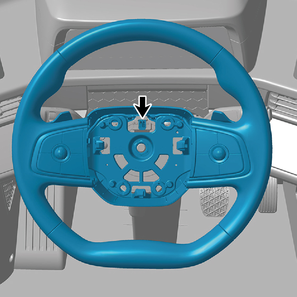
assembly.
7
Remove 1 fixing nut of the steering wheel assembly.
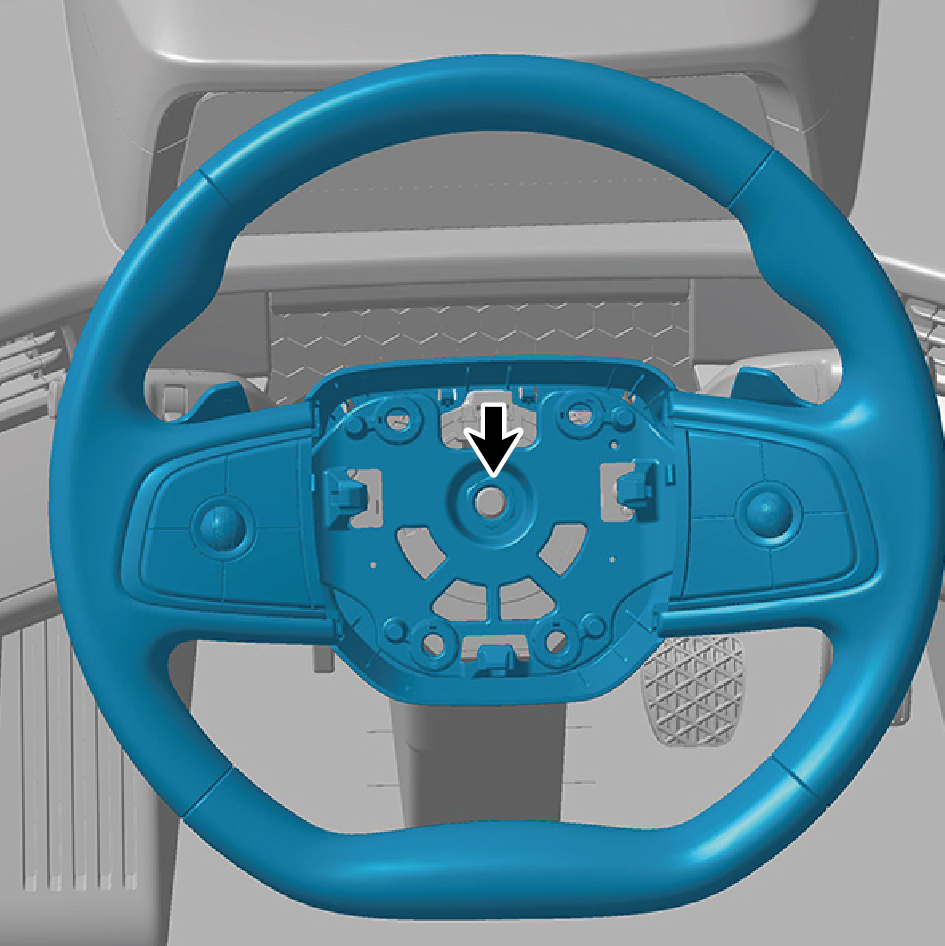
caution
Place the wheels in front of the vehicle and mark the
connection between the steering wheel assembly
and the steering column with intermediate axle
assembly with a marker pen.
8
Remove the steering wheel assembly.
caution
Do not rotate the clock spring after removing the
steering wheel assembly to prevent damage to the
clock spring.
Installation Procedures
1
Place the front wheels in front and install the steering
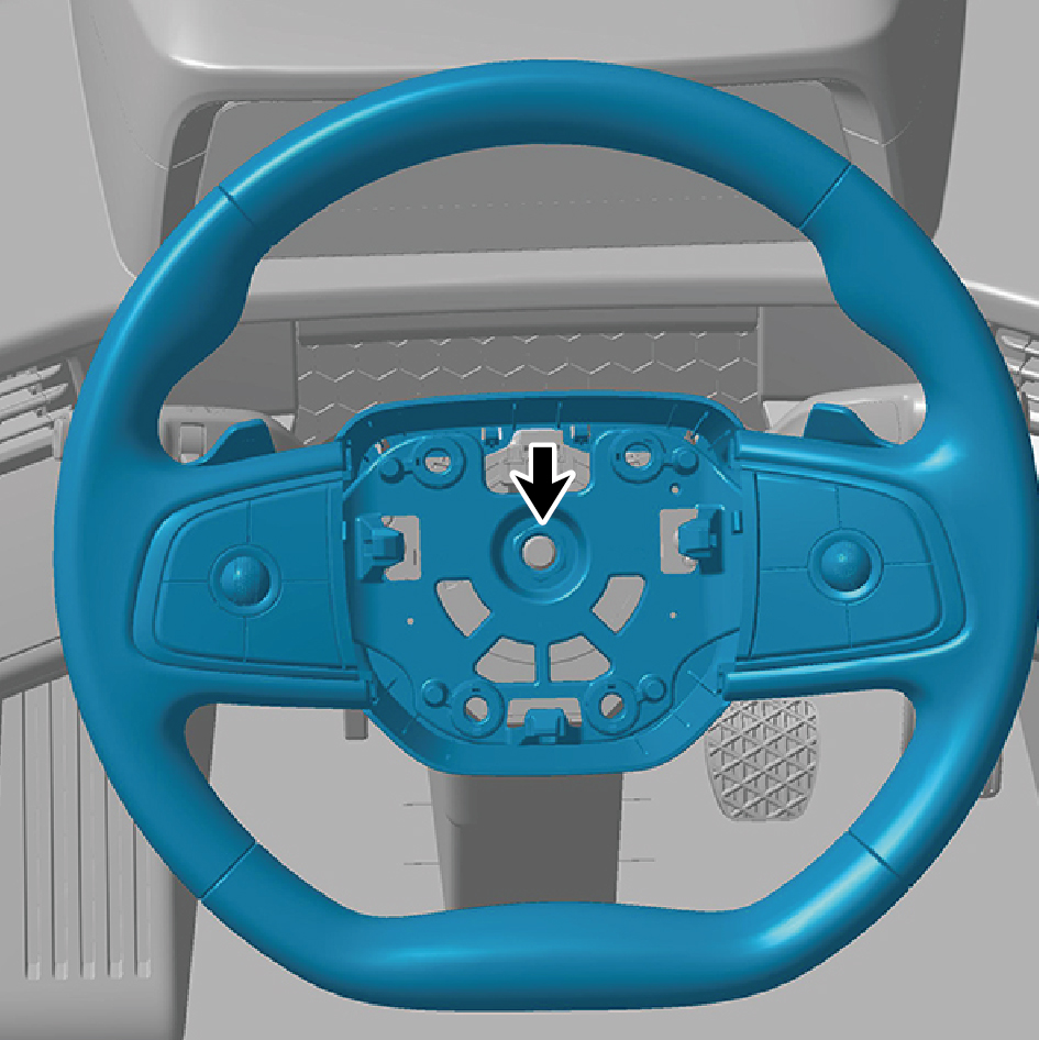
wheel assembly. Align the installation marks made with a
marker pen before removing the steering wheel assembly.
2
Install 1 fixing nut of the steering wheel assembly.
Torque: 44 +/- 3.5 (ft lbs)
3
Connect 1 harness connector of the steering wheel
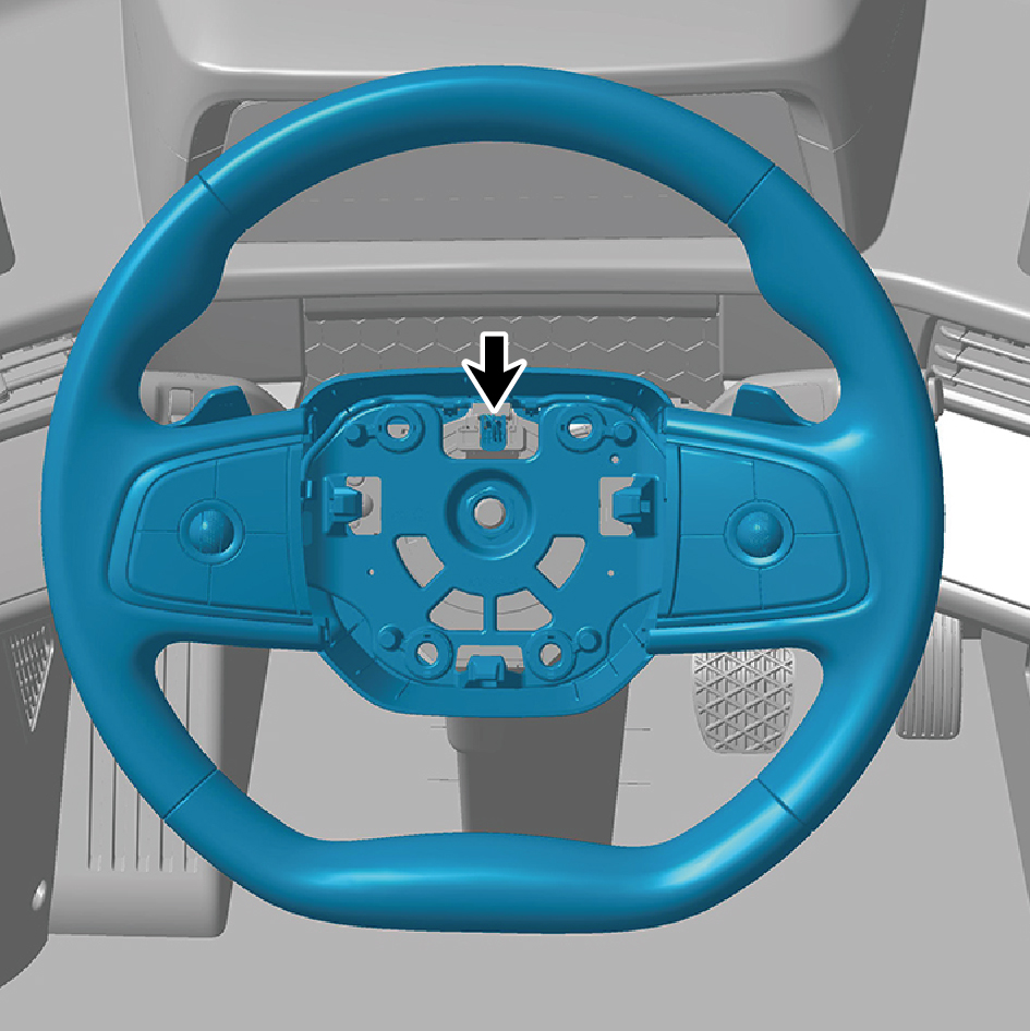
assembly.
caution
The harness is firmly connected following the
principal of "insert until a click is heard for
confirmation".
4
Install the driver horn cover assembly.
5
Install the combination switch lower shield.
6
Connect the battery negative cable.
7
Close the front flip cover plate.
8
Close the door.
8.12.3.2 Replacement of Steering Column Assembly
Assembly
Removal Procedures
1
Open the door.
2
Open the front flip cover plate.
3
Disconnect the battery negative cable.
caution
power down the high-voltage system before
disconnecting the negative pole of the storage
battery.
4
Remove the combination switch upper shield assembly.
5
Remove the combination switch lower shield.
6
Remove the IP left access cover plate assembly.
7
Remove the left switch panel assembly.
8
Remove the left switch panel lower trim panel assembly.
9
Remove the IP left front trim panel assembly.
10
Remove the IP right access cover plate assembly.
11
Remove the right switch panel assembly.
12
Remove the right switch panel lower trim panel assembly.
13
Remove the IP right front lower trim panel assembly.
14
Remove the IP right front upper trim panel assembly.
15
Remove the steering column lower shield assembly.
16
Remove the driver horn cover assembly.
17
Remove the steering wheel assembly.
18
Remove the clock spring.
19
Remove the combination switch.
20
Remove the combination switch fixing bracket.
21
Remove the steering angle sensor assembly.
22
Remove the pillar lock.
23
Remove the combination switch lower shield mounting
bracket.
24
Remove 6 fixing bolts of the steering column assembly.
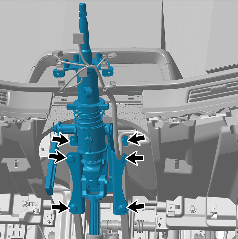
25
Remove the steering column assembly.
Installation Procedures
1
Move the steering column assembly to the mounting
position.
2
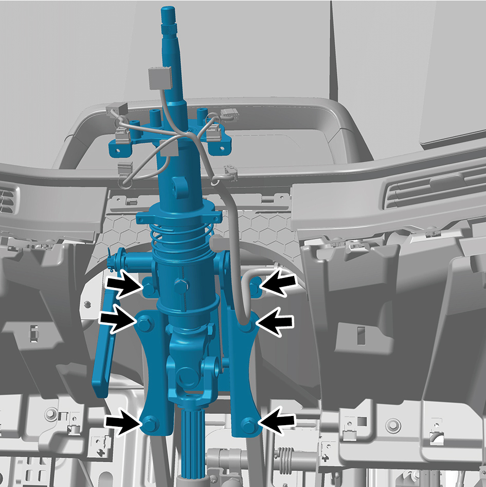
Install 6 fixing bolts of the steering column assembly.
Torque: 18.5 +/- 2 (ft lbs)
3
Install the pillar lock.
4
Install the combination switch lower shield mounting
bracket.
5
Install the steering angle sensor assembly.
6
Install the combination switch fixing bracket.
7
Install the combination switch.
8
Install the clock spring.
9
Install the steering wheel assembly.
10
Install the driver horn cover assembly.
11
Install the steering column lower shield assembly.
12
Install the IP right front upper trim panel assembly.
13
Install the IP right front lower trim panel assembly.
14
Install the right switch panel lower trim panel assembly.
15
Install the right switch panel assembly.
16
Install the IP right access cover plate assembly.
17
Install the IP left front trim panel assembly.
18
Install the left switch panel lower trim panel assembly.
19
Install the left switch panel assembly.
20
Install the IP left access cover plate assembly.
21
Install the combination switch lower shield.
22
Install the combination switch upper shield assembly.
23
Connect the battery negative cable.
24
Close the front flip cover plate.
25
Close the door.
8.12.3.3 Replacement of Driver Horn Cover Assembly
Assembly
Removal Procedures
1
Open the door.
2
Open the front flip cover plate.
3
Disconnect the battery negative cable.
caution
power down the high-voltage system before
disconnecting the negative pole of the storage
battery.
4
Remove the combination switch upper shield assembly.
5
Remove the combination switch lower shield.
6
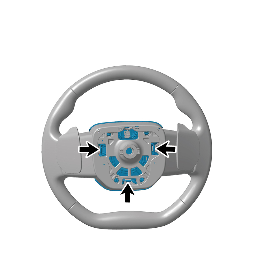
Release 3 circlips of the driver horn cover assembly.
7
Disconnect one harness connector,Remove the driver
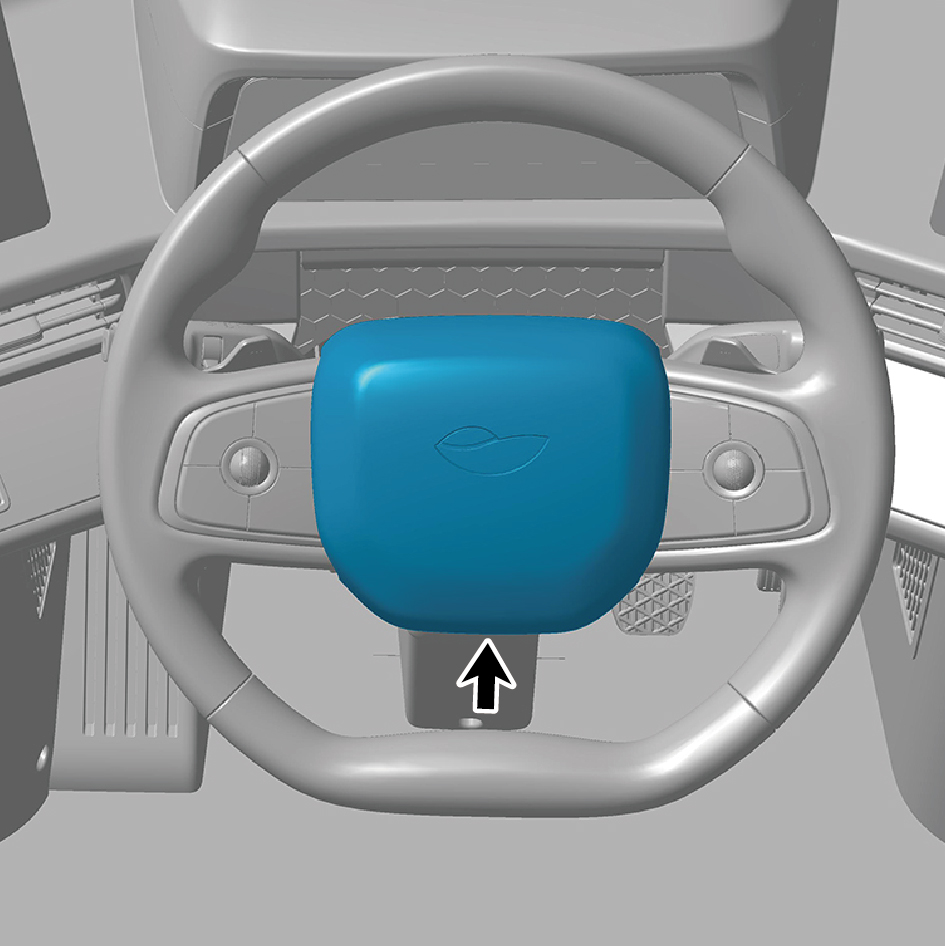
horn cover assembly.
Installation Procedures
1
Install the driver horn cover assembly,connect one
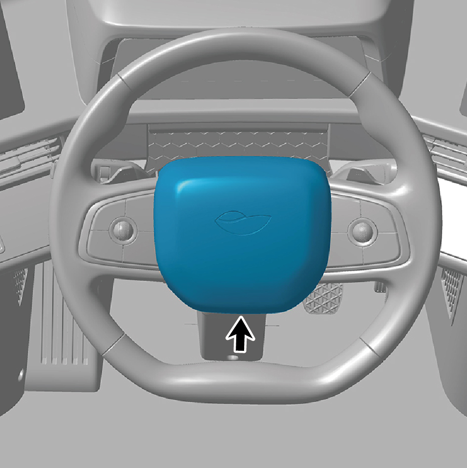
harness connector.
2
Install the combination switch lower shield.
3
Install the combination switch upper shield assembly.
4
Connect the battery negative cable.
5
Close the front flip cover plate.
6
Close the door.