← Back to Contents
8 Chassis / 8.11 Steering Rod Device | PDF pages 2039-2054
8.11 Steering Rod Device
8.11 Steering Rod Device
8.11.1 Specifications
8.11.1.1 Fastener Specifications
Range Of Torque
Fastener Specifications
Specifications
Foot Pounds of Torque (ft lbs)
Fixed bolts connecting the driven rocker
155 +/- 14.75 (ft lbs)
M14
arm to the frame on the subframe
The fixing nut connecting the driven
155 +/- 14.75 (ft lbs)
rocker arm and the frame on the
M14
subframe
The fixing nut connecting the tie rod and
254 +/- 11 (ft lbs)
M24
relay rod
The fixing nut connecting the tie rod and
498 +/- 18.5 (ft lbs)
M45
relay rod
The fixing nut connecting the active
254 +/- 11 (ft lbs)
M24
rocker arm and the relay rod
8.11.2 Decomposition Diagram
8.11.2.1 Decomposition Diagram
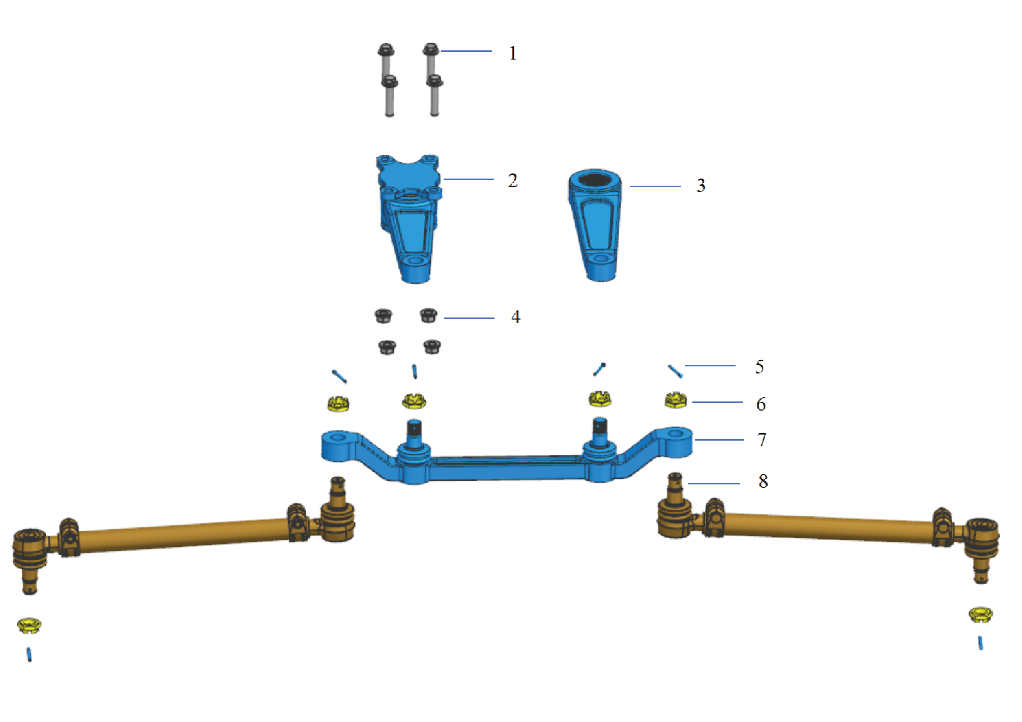
5.
1.
Hexagon Flange Bolt
Split Pin
2.
Idlerarm
6.
Hexagon Slotted Thin Nut
7.
3.
Pitman Arm
Relay Rod
4.
Hexagon Flange Nut
8.
Tie Rod
8.11.3 Dismantling and Installation
8.11.3.1 Replacement of Relay Rod
Removal Procedures
1
Jack the front end of the vehicle.
2
Remove the guide wheel (left).
3
Remove the guide wheel (right).
4
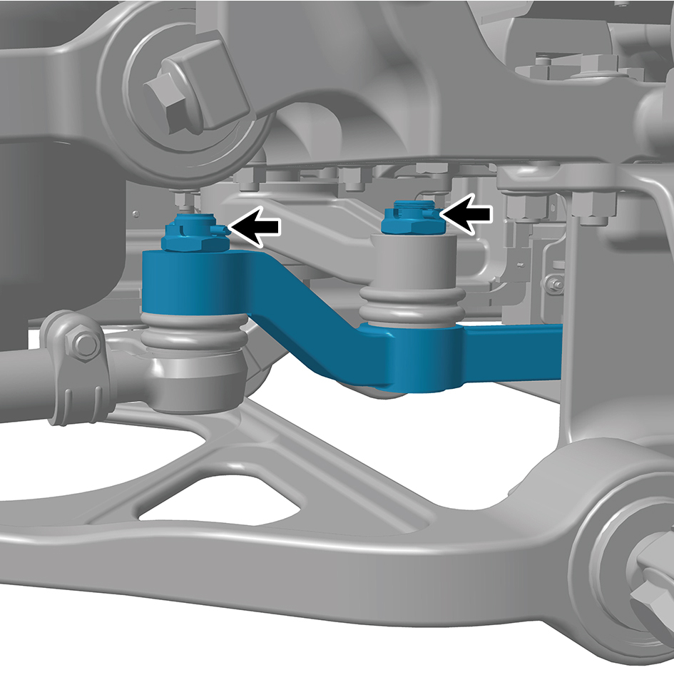
Remove 4 fixing pins of the relay rod.
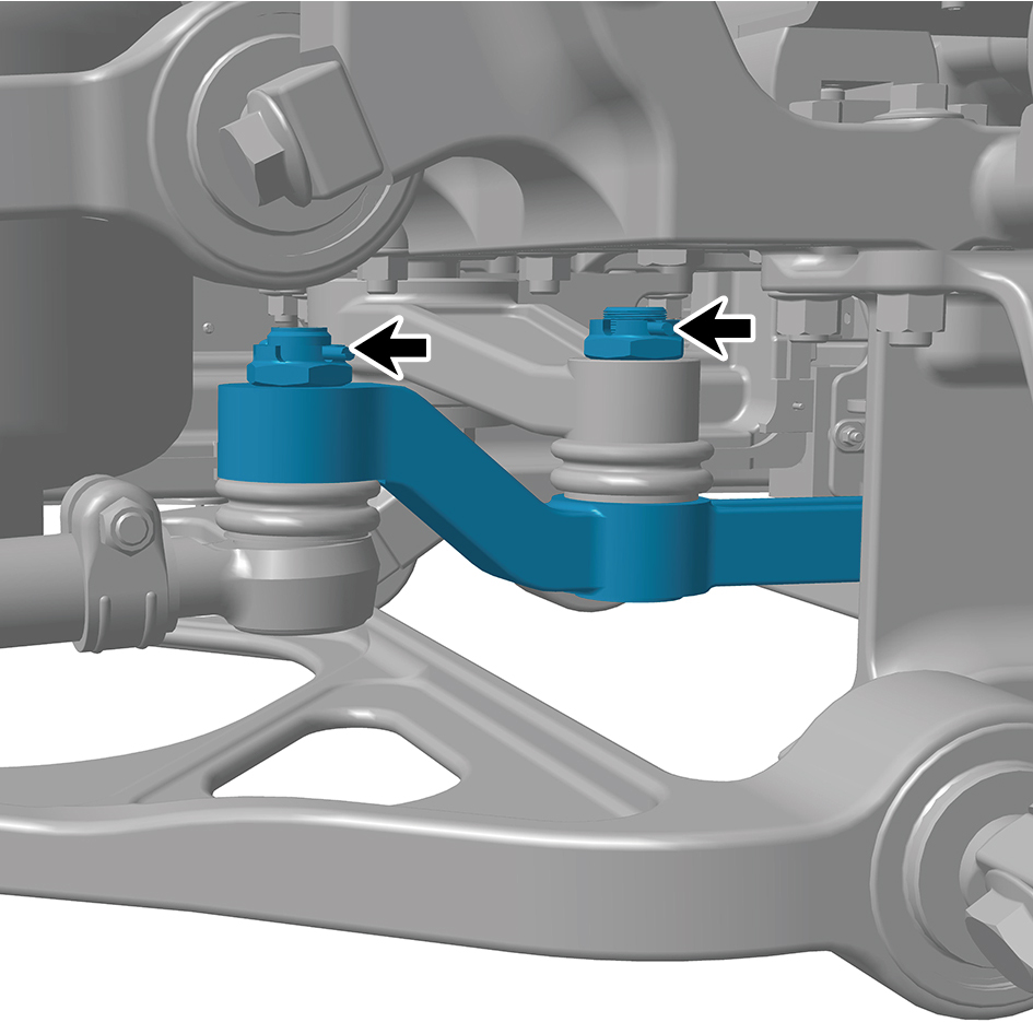
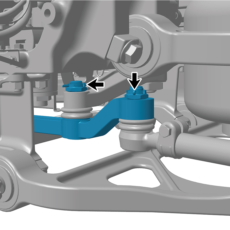
5
Remove 4 fixing nuts of the relay rod, and remove the
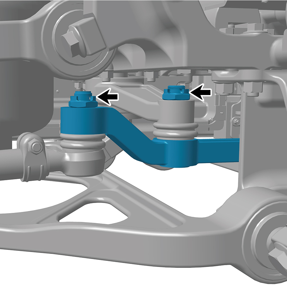
relay rod.
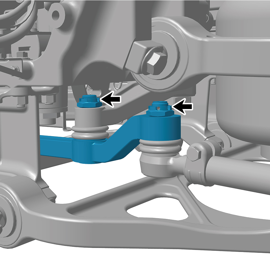
Installation Procedures
1
Move the relay rod to the mounting position.
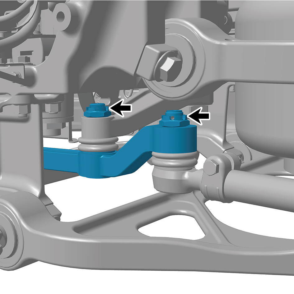
2
Install 4 fixing nuts of the relay rod.
Torque: 243 - 266 (ft lbs)
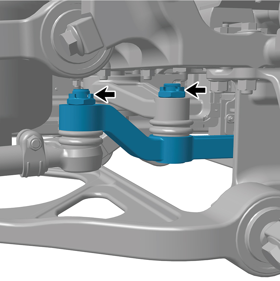
3
Install 4 fixing pins of the relay rod.
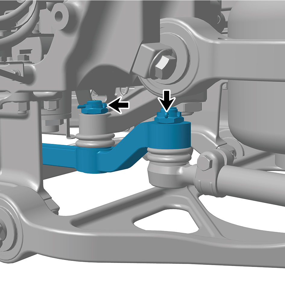
4
Remove the guide wheel (right).
5
Install the guide wheel (left).
6
Lower the front end of the vehicle.
8.11.3.2 Replacement of Driving Rocker Arm
Removal Procedures
1
Jack the front end of the vehicle.
2
Remove the guide wheel.
3
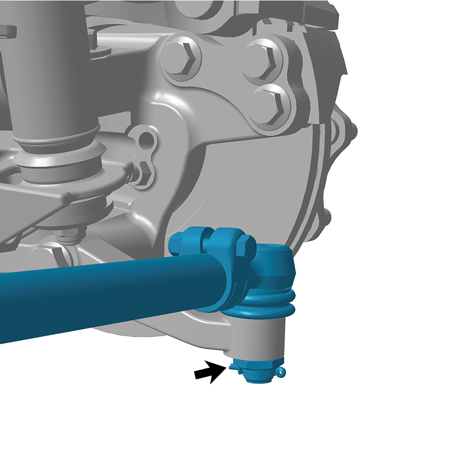
Remove 1 fixing pin.
4
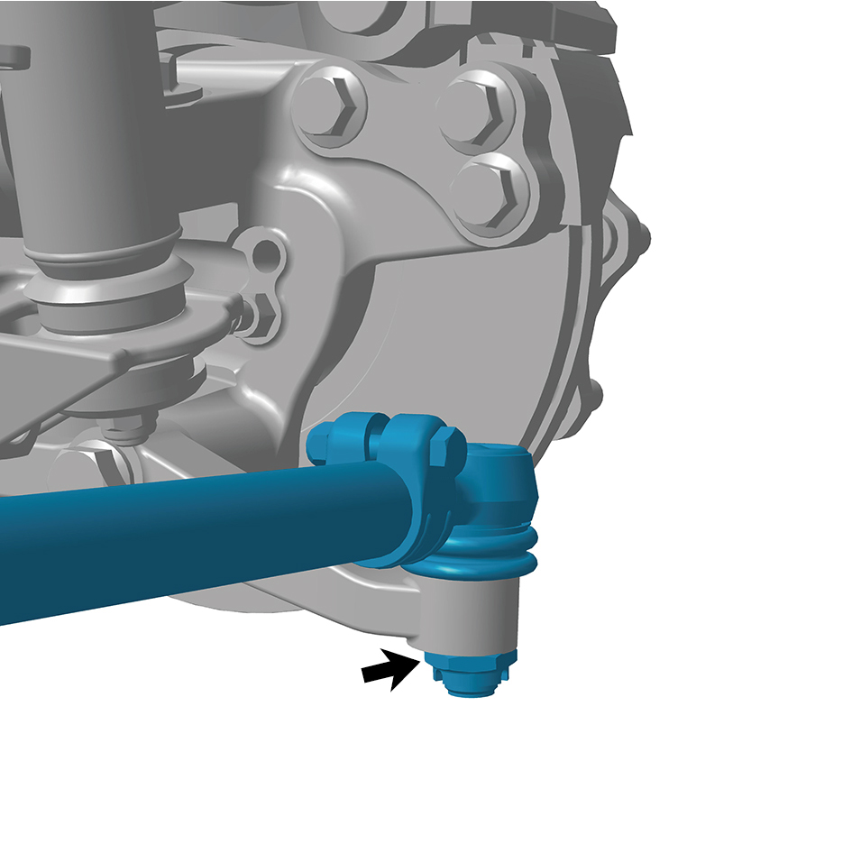
Remove 1 fixing nut of the tie rod.
5
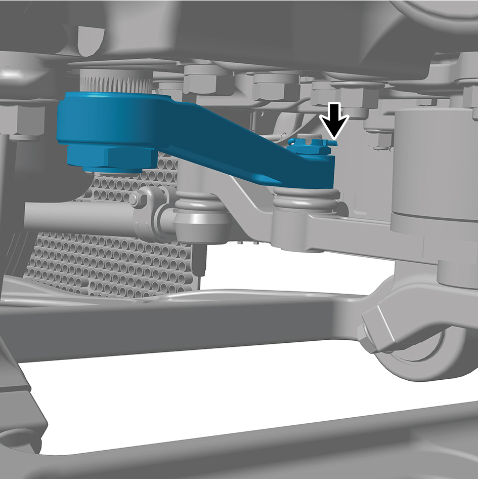
Remove 1 fixing pin.
6
Remove 1 fixing nut of the driving rocker arm.
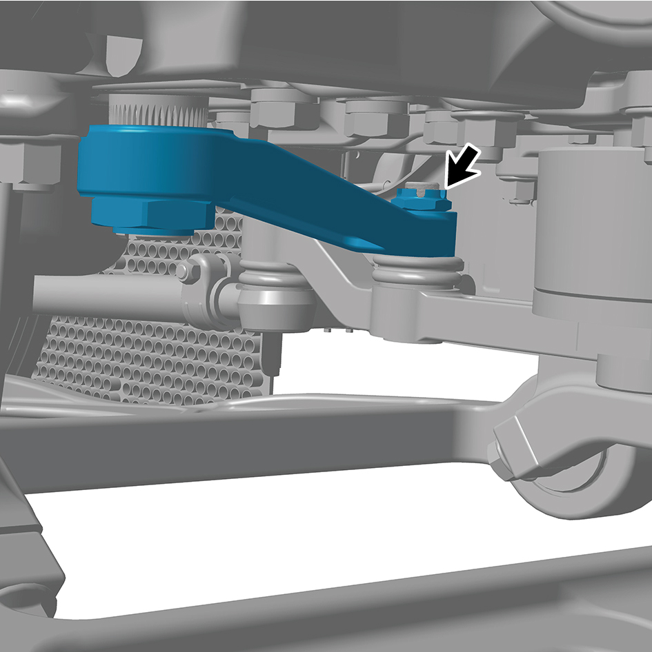
7
Remove 1 fixing nut of the driving rocker arm.
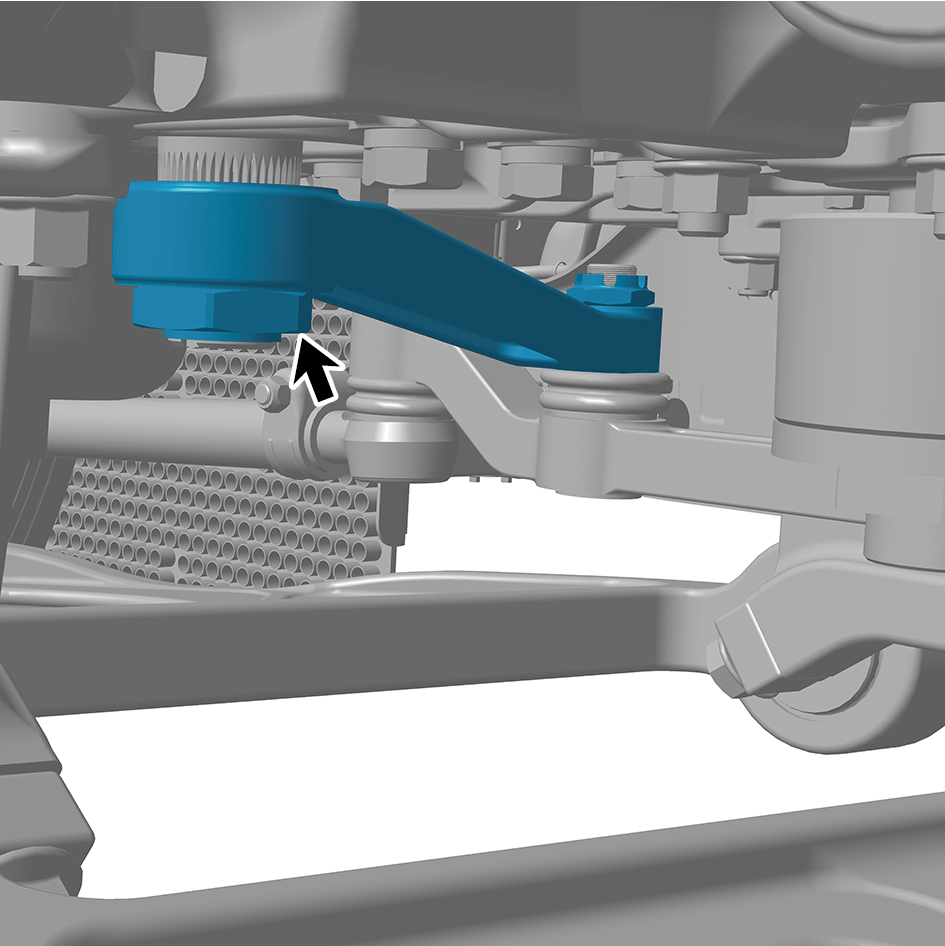
8
Remove the driving rocker arm.
Installation Procedures
1
Move the driving rocker arm to the mounting position.
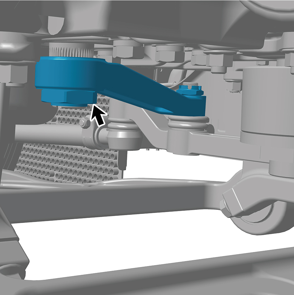
caution
It is necessary to align the engraved lines during
installation.
2
Install 1 fixing nut of the driving rocker arm.
Torque: 498 +/- 18.5 (ft lbs)
caution
When installing the nuts, it is necessary to fix the
pitman armto prevent the excessive rotation angle
from damaging the unloading valve.
3
Install 1 fixing nut of the driving rocker arm.
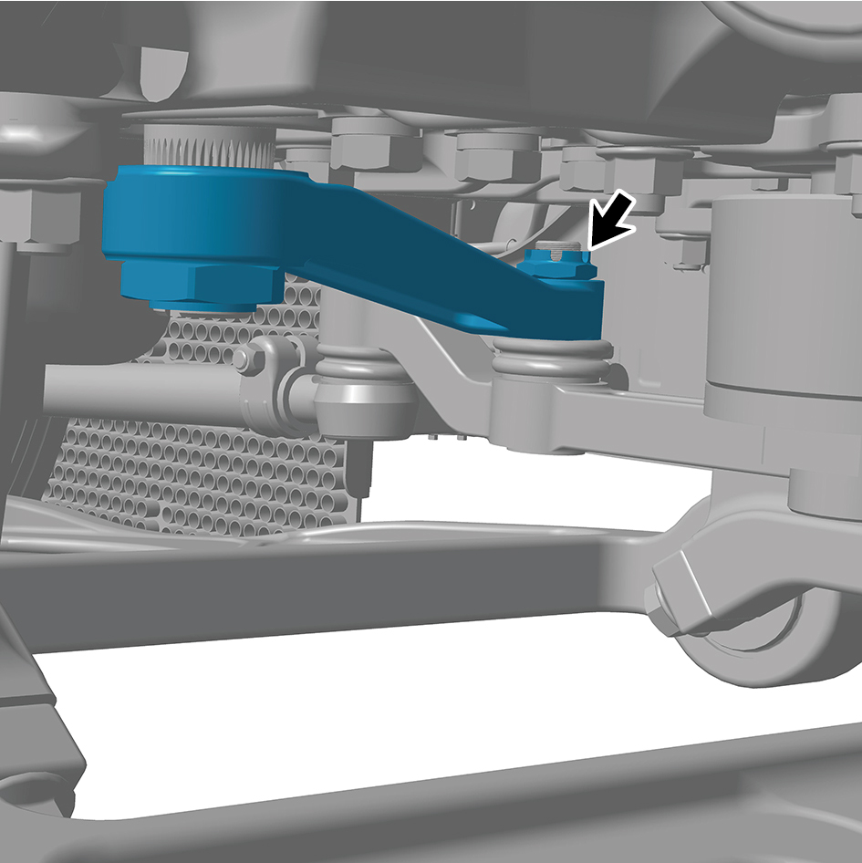
Torque: 243 - 266 (ft lbs)
4
Install 1 fixing pin.
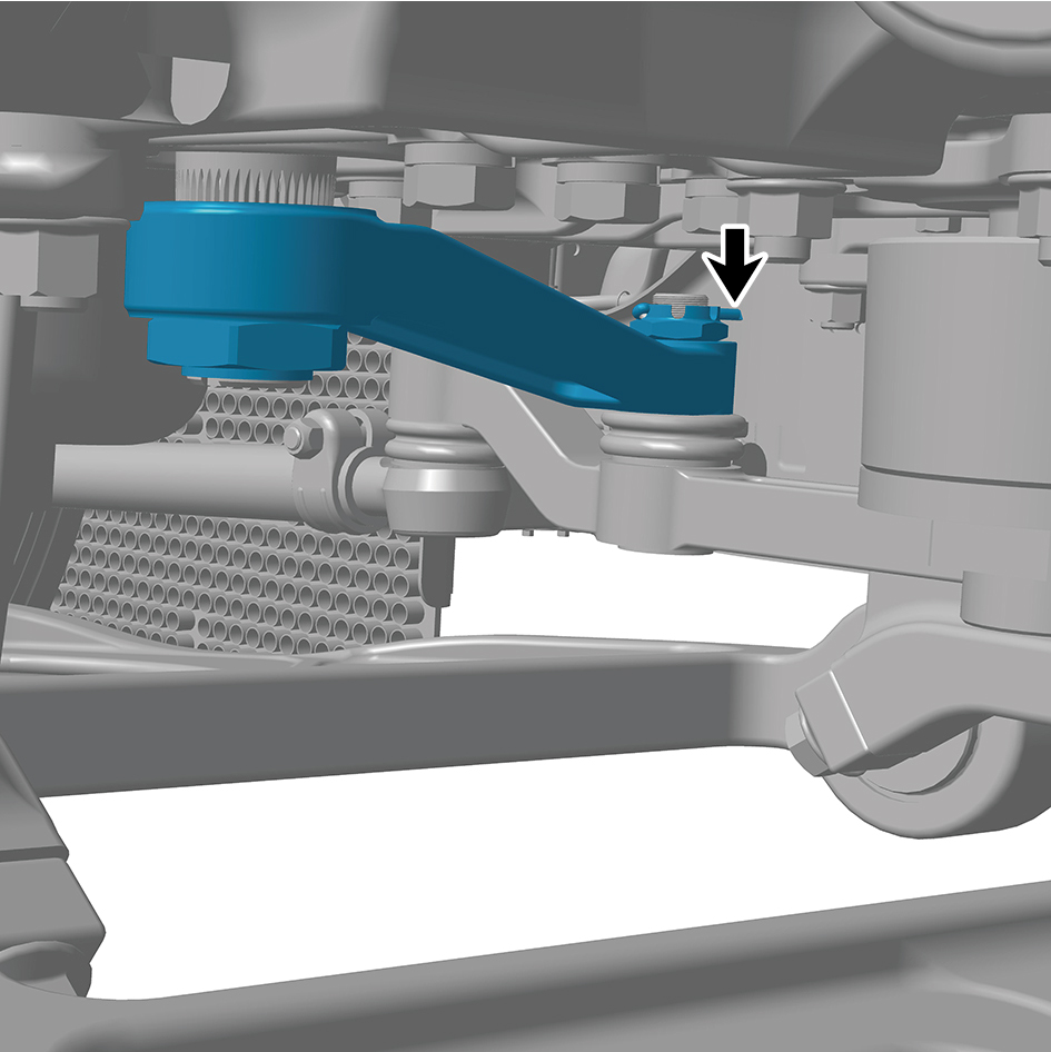
5
Install 1 fixing nut of the tie rod.
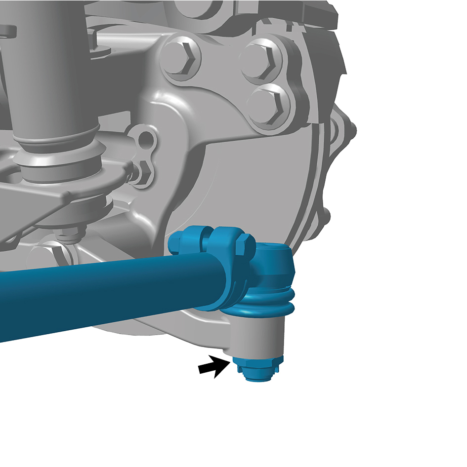
Torque: 254 +/- 11 (ft lbs)
6
Install 1 fixing pin.
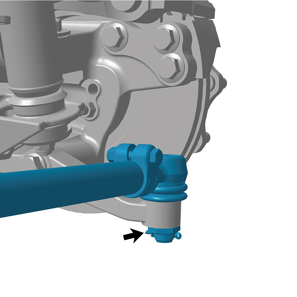
7
Install the guide wheel.
8
Lower the front end of the vehicle.
8.11.3.3 Replacement of Driven Rocker Arm
Removal Procedures
1
Jack the front end of the vehicle.
2
Remove the guide wheel (left).
3
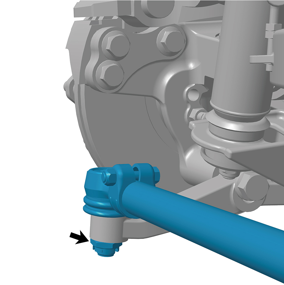
Remove 1 fixing pin.
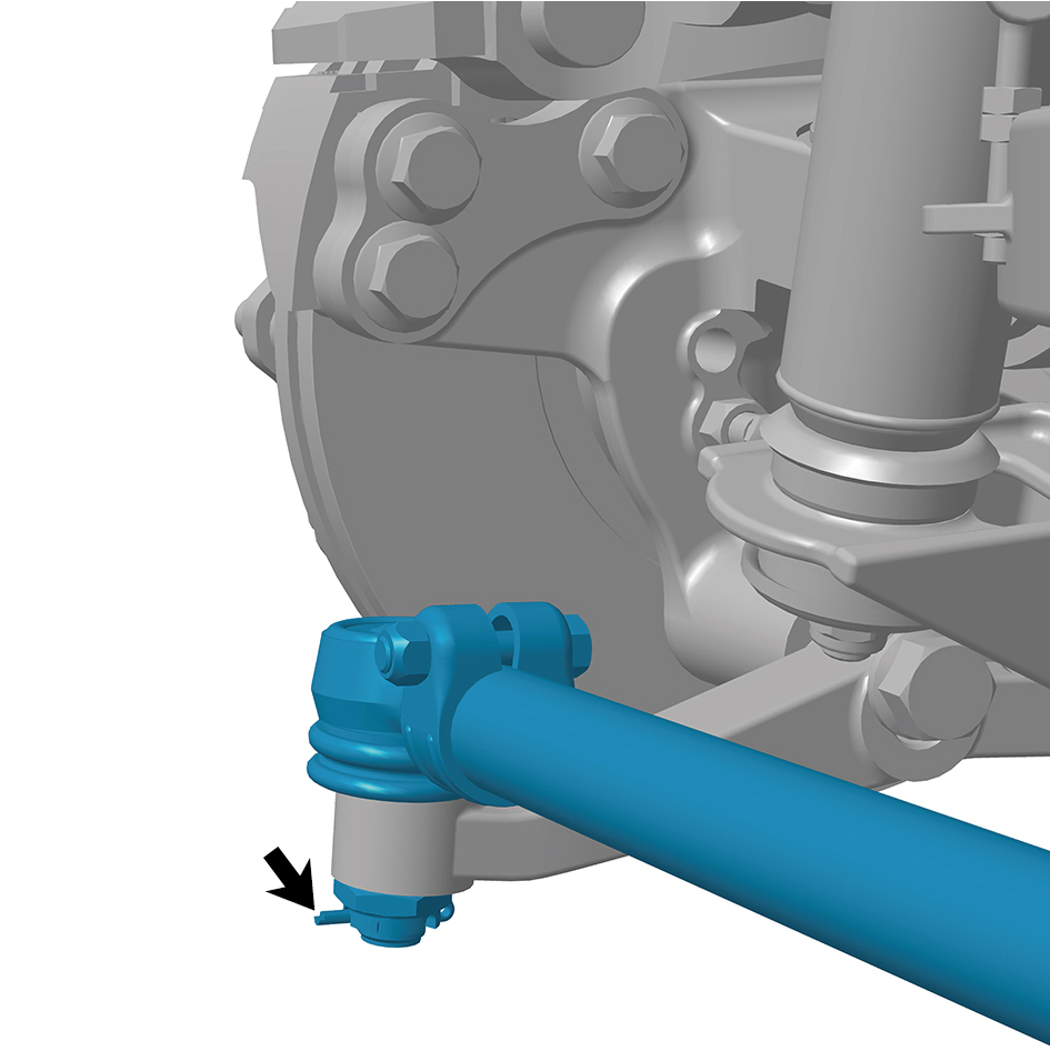
4
Remove 1 fixing nut of the relay rod.
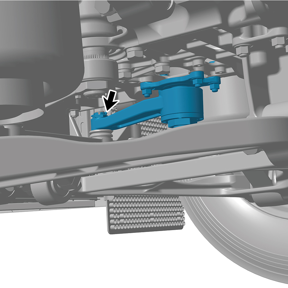
5
Remove 1 fixing pin.
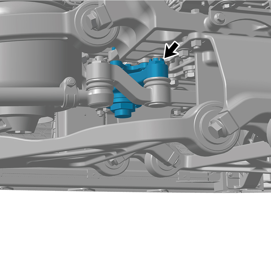
6
Remove 1 fixing nut of the driven rocker arm.
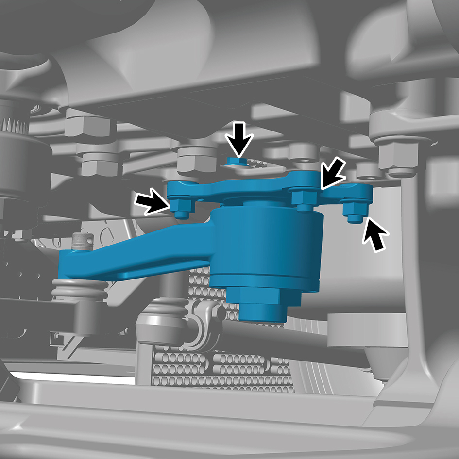
7
Remove 4 bolts and nuts of the driven rocker arm.
8
Remove the driven rocker arm.
Installation Procedures
1
Move the driven rocker arm to the mounting position.
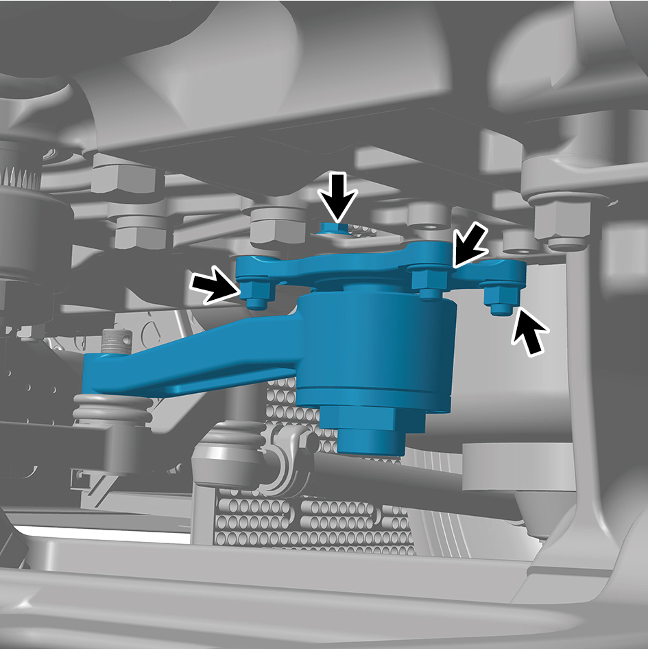
2
Install 4 bolts and nuts of the driven rocker arm.
Torque: 155 +/- 14.75 (ft lbs)
3
Install 1 fixing nut of the driven rocker arm.
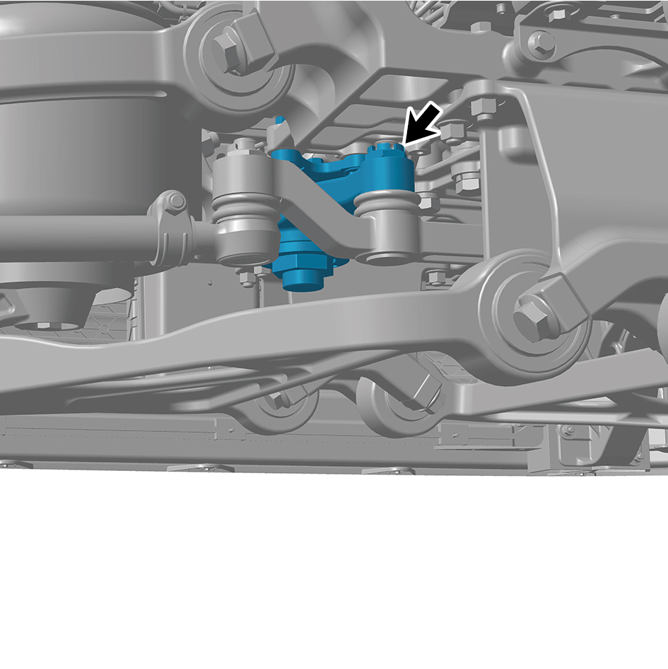
Torque:243 - 266 (ft lbs)
4
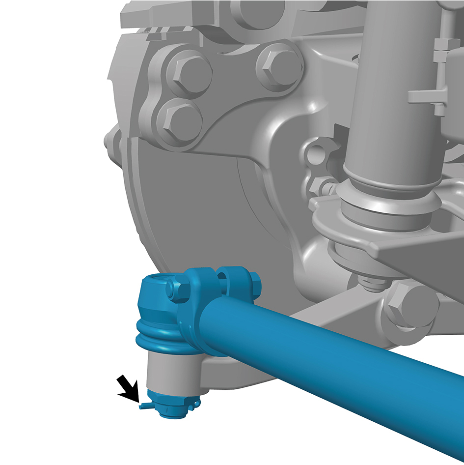
Install 1 fixing pin.
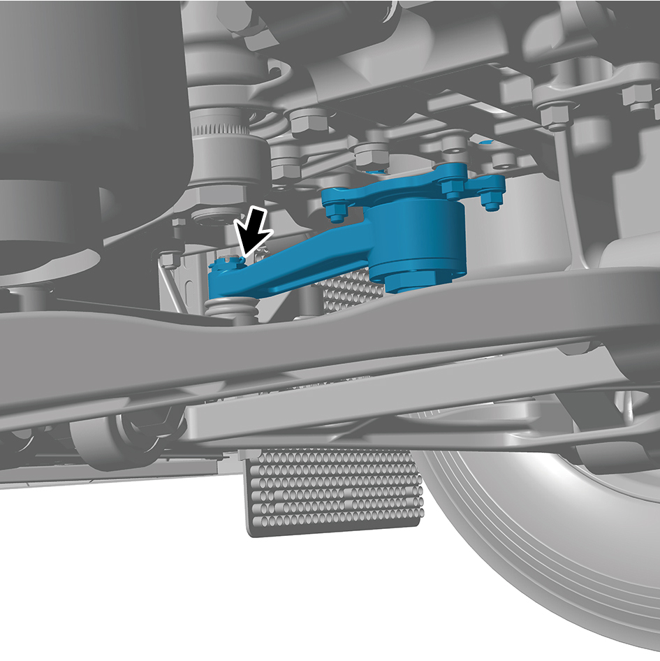
5
Install 1 fixing nut of the relay rod.
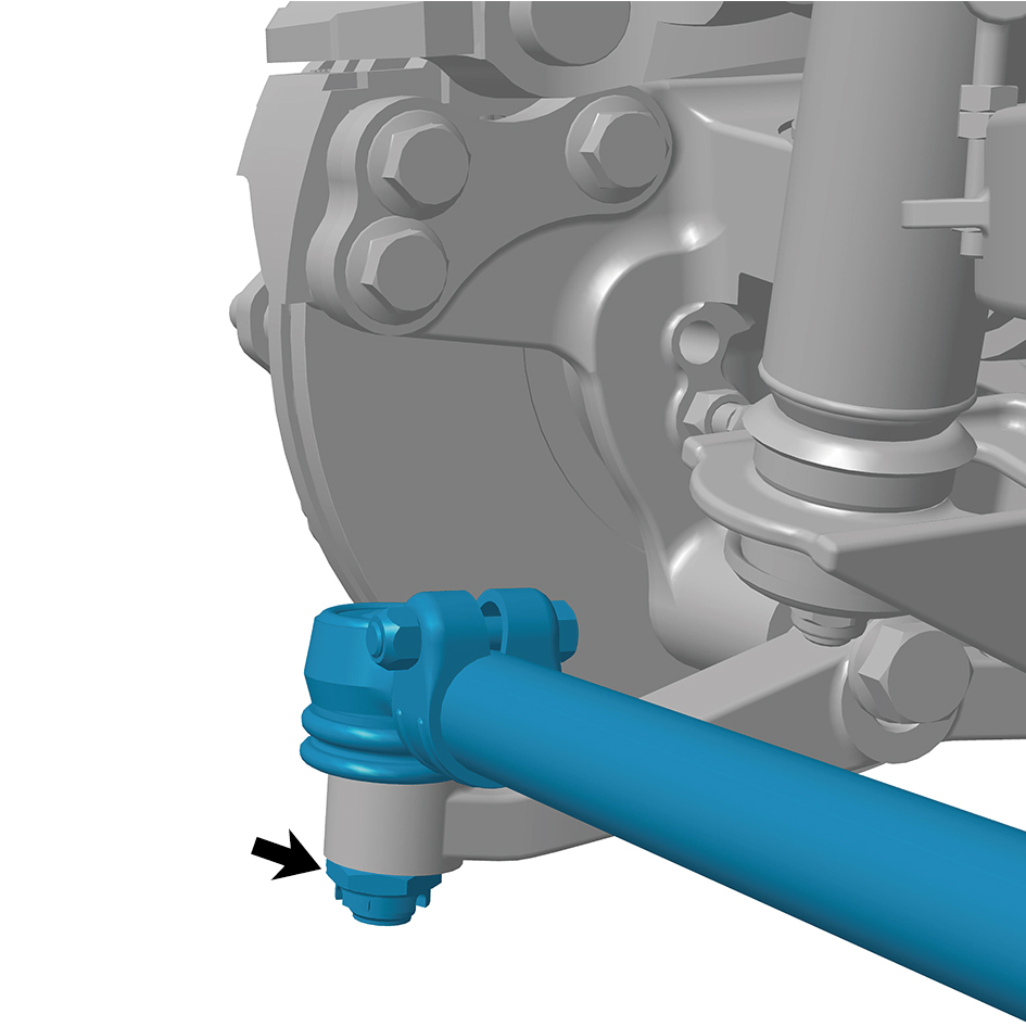
6
Install 1 fixing pin.
7
Install the guide wheel (right).
8
Lower the front end of the vehicle.
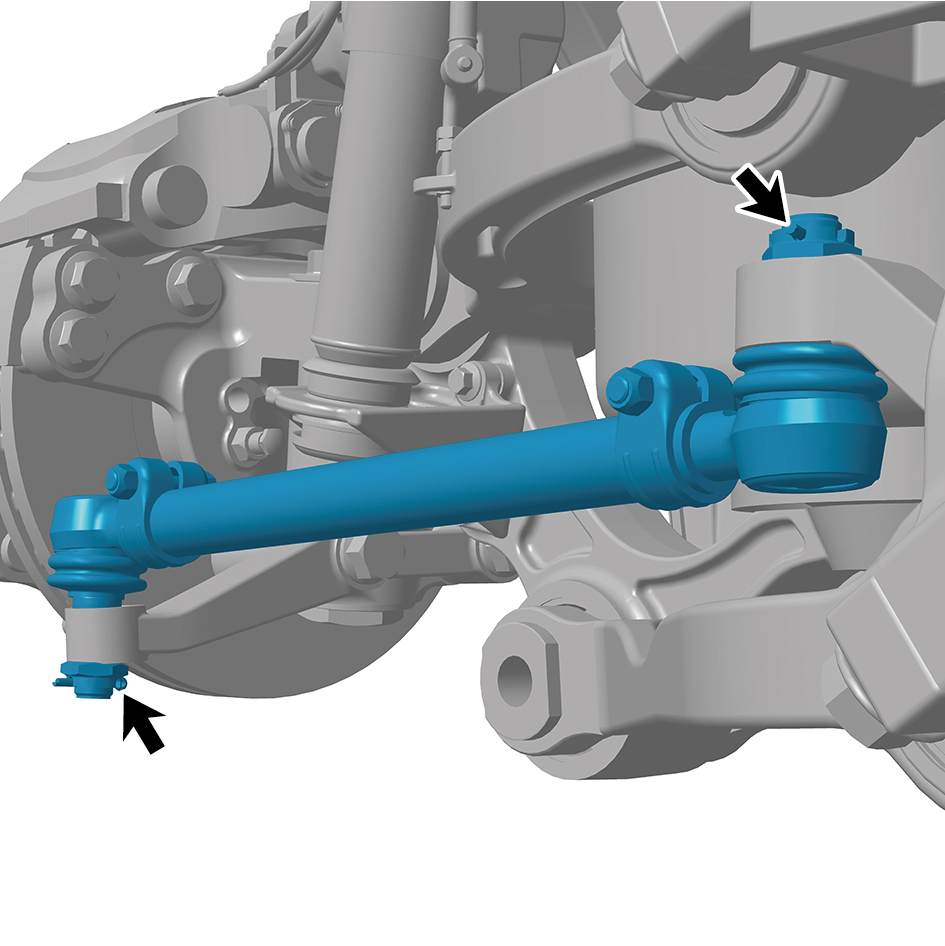
8.11.3.4 Replacement of Tie Rod
Removal Procedures
1
Jack the front end of the vehicle.
2
Remove the guide wheel.
3
Remove 2 fixing pins of the tie rod.
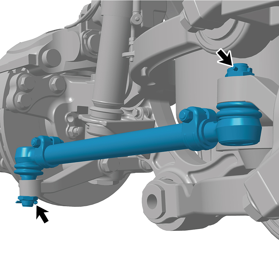
4
Remove 2 fixing nut of the tie rod.
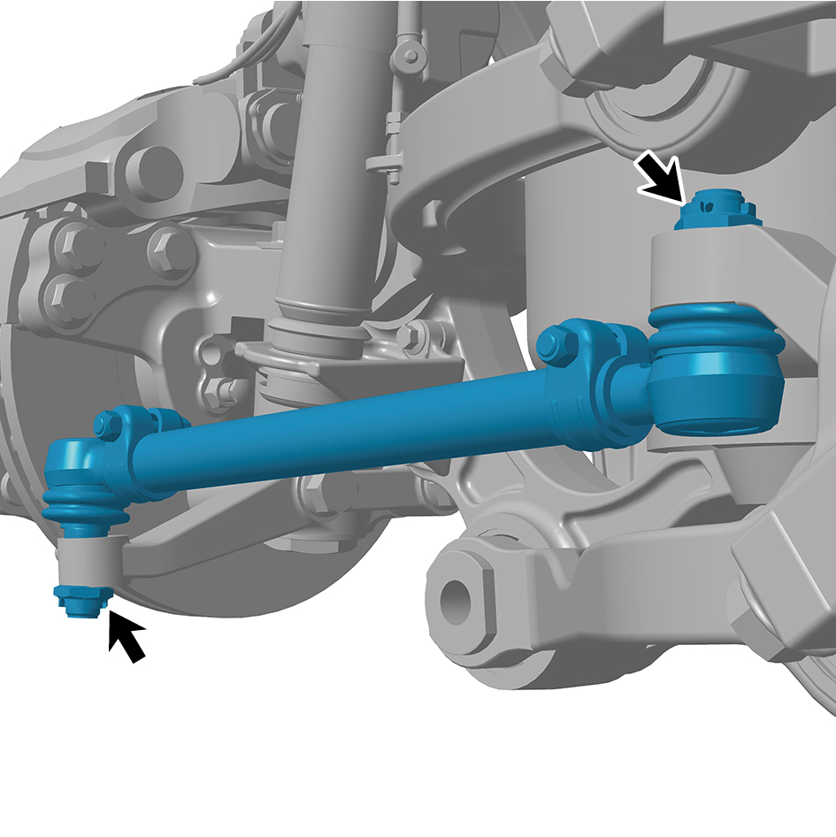
5
Remove the tie rod.
Installation Procedures
1
Move the tie rod to the mounting position.
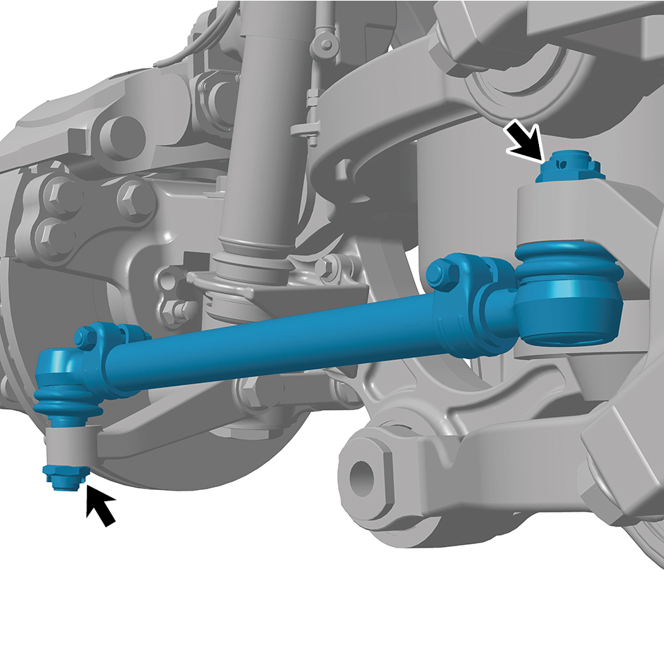
2
Install 2 fixing nuts of the tie rod.
Torque: 254 +/- 11 (ft lbs)
3
Install 2 fixing pins of the tie rod.
4
Install the guide wheel.
5
Lower the front end of the vehicle.
caution
After part replacement, it is necessary to perform
four-wheel alignment.