← Back to Contents
8 Chassis / 8.10 Tire Pressure Monitoring System | PDF pages 2015-2038
8.10 Tire Pressure Monitoring System
8.10 Tire Pressure Monitoring System
8.10.1 Specifications
8.10.1.1 Fastener Specifications
Range Of Torque
Fastener Specifications
Specifications
Foot Pounds of Torque (ft lbs)
The fixing nut connecting the tire
pressure relay and the tire preThe fixing
bolt connecting the tire pressure relay
(2 +/- .5) ft lbs
M4
and the tire pressure monitoring module
bracket 2ssure monitoring module
bracket 2
The fixing nut connecting the tire
pressure relay and the tire pressure
(2 +/- .5) ft lbs
M4
monitoring module bracket 2
The fixing bolt connecting the tire
pressure monitoring module bracket 2 to
(18.5 +/- 2) ft lbs
M8
the frame assembly
The fixing bolt connecting the tire
pressure CAN module and the tire
(6.5 +/- .75) ft lbs
M6
pressure monitoring module bracket
The fixing bolt connecting the tire
pressure monitoring module bracket to
(133 +/- 11) ft lbs
M14
the frame assembly
The fixing nut connecting the tire
pressure monitoring module bracket to
(133 +/- 11) ft lbs
M14
the frame assembly
8.10.2 Decomposition Diagram
8.10.2.1 Decomposition Diagram
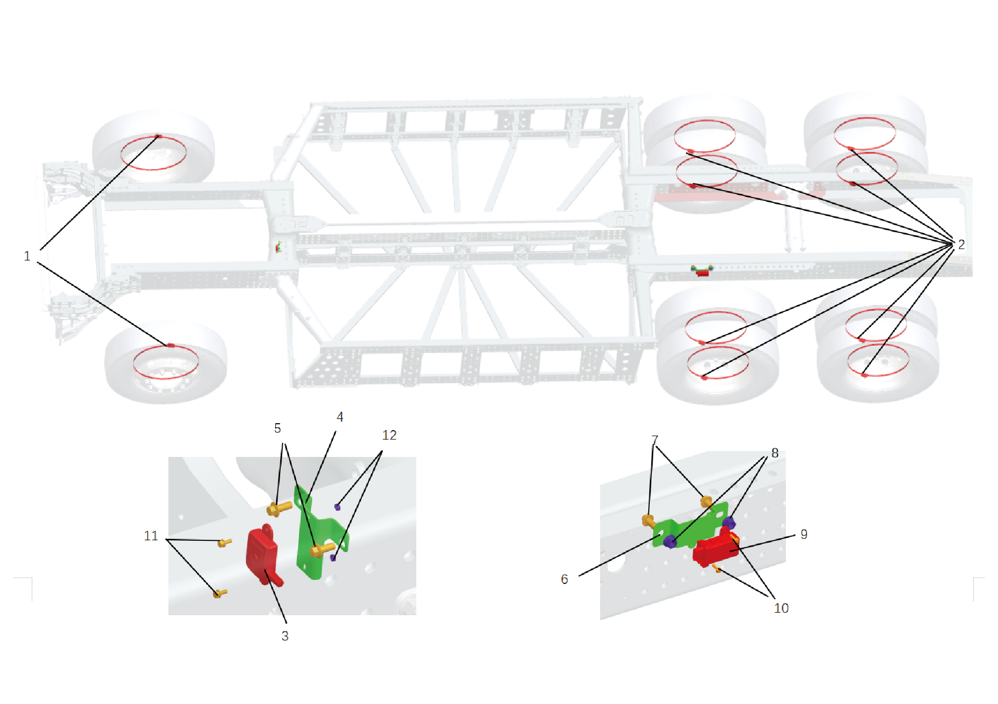
7.
1.
Hexagon Flange Bolt
Front Tire Pressure Monitoring Sensor
2.
Rear Tire Pressure Monitoring Front Tire Pressure
8.
Hexagon Flange Lock Nut_All Metal
Monitoring Sensor
3.
9.
Tire Pressure Repeater
Tire Pressure CAN Module
4.
10.
Hexagon Flange Bolt
Tire Pressure Monitoring System Bracket 2
5.
Hexagon Flange Bolt
11.
Hexagon Head Bolt Assy
6.
12.
Hexagon Nut_Type 1
Tire Pressure Monitoring System Bracket 2
8.10.3 System Schematic Diagram
8.10.3.1 Electrical Schematic Diagram
8.10.4 Diagnostic Information and Steps
8.10.4.1 Diagnostic Description
Before diagnosing the malfunction of the tire pressure monitoring device, it is important to understand and familiarize oneself with
the working principle of the tire pressure monitoring device before starting the system diagnosis. This will help determine the
correct fault diagnosis steps when a malfunction occurs, and more importantly, it will help determine the situation described by
the customer belongs to normal operation. Any fault diagnosis of tire pressure monitoring devices should start with routine
inspection, guiding maintenance personnel to take the next logical step for fault diagnosis. Understanding and correctly using the
diagnostic process can shorten the diagnosis time and avoid misjudgment of faulty parts.
8.10.4.2 Routine Inspection
• Check for aftermarket devices that may affect the operation of the tire pressure monitoring system, ensuring that these devices
do not affect the operation of the tire pressure monitoring system.
• Check system components that are easily accessible or visible to ensure that there is no obvious damage or potential
malfunction.
8.10.4.3 Fault Symptom Table
Symptom
Suspected Faulty Project
Measures
Adjust the tire pressure to the standard
1.Low or high tire pressure
pressure range.
Abnormal tire pressure system
Restore the vehicle and recalibrate the
2.Modified tires or wheels
malfunction indicator light
tire pressure system.
3.Rear tire pressure module power
Refer to Rear Tire Pressure Module
failure
Power Failure
8.10.4.4 DTC Confirmation
1. Connect the diagnostic tool to the diagnostic interface, read and record the DTC, and then clear the DTC.
2. Run the vehicle again.
3. Read the fault code of the control system again to confirm if there is any fault code output from the system.
– Yes:Diagnose based on the output fault code.
– No:Perform intermittent fault check, refer to Inspection Of Intermittent Faults
8.10.4.5 List Of Diagnostic Trouble Codes (DTC)
TMPS
Fault Description
Exclusion Method
Fault Code
Battery Voltage Tool low
B111716
Refer to Rear Tire Pressure Module
Power Fault
Battery Voltage Too High
B111717
U007C88
BCANFD1 BusOff
U012287
Lost Communication With VDC
Refer to Rear Tire Pressure Module
Communication Fault
U015687
Lost Communication With CDCU
U019887
Lost Communication With TGW
The transmitter of the No.1 wheel
B220000
position is faulty
Refer to Wheel Position Transmitter
Fault
The battery of the transmitter at the
B220001
No.1 wheel position is running low
Fault Description
Exclusion Method
Fault Code
The transmitter of the No.1 wheel
B220002
position gives a high - temperature
alarm
The transmitter of the No.2 wheel
B220003
position is faulty
The battery of the transmitter at the
B220004
No.2 wheel position is running low
The transmitter of the No.2 wheel
B220005
position gives a high-temperature alarm
The transmitter of the No.3 wheel
B220006
position is faulty
The battery of the transmitter at the
B220007
No.3 wheel position is running low
The transmitter of the No.3 wheel
B220008
position gives a high-temperature alarm
The transmitter of the No.4 wheel
B220009
position is faulty
The battery of the transmitter at the
B22000A
No.4 wheel position is running low
The transmitter of the No.4 wheel
B22000B
position gives a high-temperature alarm
The transmitter of the No.5 wheel
B22000C
position is faulty
The battery of the transmitter at the
B22000D
No.5 wheel position is running low
The transmitter of the No.5 wheel
B22000E
position gives a high-temperature alarm
The transmitter of the No.6 wheel
B22000F
position is faulty
The battery of the transmitter at the
B220010
No.6 wheel position is running low
The transmitter of the No.6 wheel
B220011
position gives a high-temperature alarm
The transmitter of the No.7 wheel
B220012
position is faulty
The battery of the transmitter at the
B220013
No.7 wheel position is running low
The transmitter of the No.7 wheel
B220014
position gives a high-temperature alarm
Fault Description
Exclusion Method
Fault Code
The transmitter of the No.8 wheel
B220015
position is faulty
The battery of the transmitter at the
B220016
No.8 wheel position is running low
The transmitter of the No.8 wheel
B220017
position gives a high-temperature alarm
The transmitter of the No.9 wheel
B220018
position is faulty
The battery of the transmitter at the
B220019
No.9 wheel position is running low
The transmitter of the No.9 wheel
B22001A
position gives a high-temperature alarm
The transmitter of the No.10 wheel
B22001B
position is faulty
The battery of the transmitter at the
B22001C
No.10 wheel position is running low
The transmitter of the No.10 wheel
B22001D
position gives a high-temperature alarm
The transmitter of the No.11 wheel
B22001E
position is faulty
The battery of the transmitter at the
B22001F
No.11 wheel position is running low
The transmitter of the No.11 wheel
B220020
position gives a high-temperature alarm
The transmitter of the No.12 wheel
B220021
position is faulty
The battery of the transmitter at the
B220022
No.12 wheel position is running low
The transmitter of the No.12 wheel
B220023
position gives a high-temperature alarm
The transmitter of the No.13 wheel
B220024
position is faulty
The battery of the transmitter at the
B220025
No.13 wheel position is running low
The transmitter of the No.13 wheel
B220026
position gives a high-temperature alarm
The transmitter of the No.14 wheel
B220027
position is faulty
The battery of the transmitter at the
B220028
No.14 wheel position is running low
Fault Description
Exclusion Method
Fault Code
The transmitter of the No.14 wheel
B220029
position gives a high-temperature alarm
8.10.4.6 Rear Tire Pressure Module Power Fault
1. DTC Monitoring Logic
Description
DTC Trigger Conditions
Faulty Part
DTC Code
Battery Voltage Tool
1. Main battery
Voltage < 18V, t > 1000ms
B111716
low
2. Low voltage
charging system
3. Wiring harness
Battery Voltage Too
Voltage > 32V, t > 1000ms
B111717
4.Rear tire
High
pressure module
2.Circuit Diagram
Smart Junction Box - Chassis
Battery
C4-5
Tire pressure
O405
Power KL30 O405b
Power KL30 O405c
C28-5
C50-1
Rear tire pressure module
Tire pressure repeater
120Ω
C28-2
C28-6
C28-1
C50-2
BCANFD1-H BH01a
BCANFD1-L BL01a
Ground connection Z56
Ground Z66
20
17
I8_C_B
I8_C_B
20
17
I8_B_C
I8_B_C
BCANFD1-L BL01a
BCANFD1-H BH01a
G06
G02
B48-17
B48-37
BDCU-4
3. Diagnostic Steps
Step 1:DTC confirmation. Refer to DTC Confirmation
Step 2:Routine inspection. Refer to Routine Inspection
Step 3:Check if there are any other module power failure codes besides the rear tire pressure module?
Check the main battery. Refer to Inspection Of The Main Battery
– Yes:
Check the low-voltage charging system. Refer to DCDC1 Low-voltage Charging System Fault
Next step
– No:
Step 4:Check the power supply and grounding harness of the rear tire pressure module.
Step 5:Rewrite the configuration code, reload the software, and upgrade the rear tire pressure module.
Step 6:Replace the rear tire pressure module. Refer to Replacement Of Tire Pressure CAN Module
Step 7:Clear and confirm DTC.
8.10.4.7 Rear Tire Pressure Module Communication Fault
1. DTC Monitoring Logic
Description
DTC Trigger Conditions
Faulty Part
DTC Code
U007C88
BCANFD1 BusOff
Busoff occurred ten times in a row
Lost Communication
Detected signal (ID :0x18FEF100 lost, t > 1000ms
U012287
1. Wiring harness
With VDC
2.Rear tire
Lost Communication
Detected signal (ID :0x18FEC1EE) lost, t > 5000ms
U015687
pressure module
With CDCU
Lost Communication
Detected signal (ID :0x18FEE6EE) lost, t > 5000ms
U019887
With TGW
2.Circuit Diagram
Smart Junction Box - Chassis
Battery
C4-5
Tire pressure
O405
Power KL30 O405b
Power KL30 O405c
C28-5
C50-1
Rear tire pressure module
Tire pressure repeater
120Ω
C28-2
C28-6
C28-1
C50-2
BCANFD1-H BH01a
BCANFD1-L BL01a
Ground connection Z56
Ground Z66
20
17
I8_C_B
I8_C_B
20
17
I8_B_C
I8_B_C
BCANFD1-L BL01a
BCANFD1-H BH01a
G06
G02
B48-17
B48-37
BDCU-4
3. Diagnostic Steps
Step 1:DTC confirmation. Refer to DTC Confirmation
Step 2:Routine inspection. Refer to Routine Inspection
Step 3:Check the BCANFD1 bus communication harness. Refer to Inspection Of BCAND1 Bus Network Integrity
Step 4:Rewrite the configuration code, reload the software, and upgrade the rear tire pressure module.
Step 5:Replace the rear tire pressure module. Refer to Replacement Of Tire Pressure CAN Module
Step 6:Clear and confirm DTC.
8.10.4.8 Wheel Position Transmitter Fault
1. DTC Monitoring Logic
Description
DTC Trigger Conditions
Faulty Part
DTC Code
When the vehicle speed is greater than 20 mph, the
The transmitter of the
transmitter information has not been received
No.1 wheel position is
B220000
faulty
continuously for 10 minutes
The battery of the
transmitter at the No.1
Two consecutive frames of the transmitter battery
B220001
wheel position is
voltage less than 1.9V are received
running low
The transmitter of the
Two consecutive frames of the detected temperature
No.1 wheel position
value of the transmitter that is greater than or equal to
B220002
gives a high -
194 degrees ferenhieght are received
temperature alarm
The transmitter of the
When the vehicle speed is over 20 mph, the transmitter
No.2 wheel position is
B220003
information has not been received continuously for 10
faulty
minutes
The battery of the
1. Wiring harness
2.Wheel position
Two consecutive frames of the transmitter battery
transmitter at the No.2
B220004
transmitter
voltage less than 1.9V are received
wheel position is
running low
3.Rear tire
pressure module
The transmitter of the
Two consecutive frames of the detected temperature
No.2 wheel position
value of the transmitter that is greater than or equal to
B220005
gives a high-
194 degrees ferenhieght are received
temperature alarm
The transmitter of the
When the vehicle speed is over 20 mph, the transmitter
No.3 wheel position is
B220006
information has not been received continuously for 10
faulty
minutes
The battery of the
Two consecutive frames of the transmitter battery
transmitter at the No.3
B220007
wheel position is
voltage less than 1.9V are received
running low
The transmitter of the
Two consecutive frames of the detected temperature
No.3 wheel position
value of the transmitter that is greater than or equal to
B220008
gives a high-
194 degrees ferenhieght are received
temperature alarm
Description
DTC Trigger Conditions
Faulty Part
DTC Code
The transmitter of the
When the vehicle speed is over 20 mph, the transmitter
No.4 wheel position is
B220009
information has not been received continuously for 10
faulty
minutes
The battery of the
transmitter at the No.4
Two consecutive frames of the transmitter battery
B22000A
wheel position is
voltage less than 1.9V are received
running low
The transmitter of the
Two consecutive frames of the detected temperature
No.4 wheel position
value of the transmitter that is greater than or equal to
B22000B
gives a high-
194 degrees ferenhieght are received
temperature alarm
The transmitter of the
When the vehicle speed is over 20 mph, the transmitter
No.5 wheel position is
information has not been received continuously for 10
B22000C
faulty
minutes
The battery of the
transmitter at the No.5
Two consecutive frames of the transmitter battery
B22000D
wheel position is
voltage less than 1.9V are received
running low
The transmitter of the
Two consecutive frames of the detected temperature
No.5 wheel position
value of the transmitter that is greater than or equal to
B22000E
gives a high-
194 degrees ferenhieght are received
temperature alarm
The transmitter of the
When the vehicle speed is over 20 mph, the transmitter
No.6 wheel position is
information has not been received continuously for 10
B22000F
faulty
minutes
The battery of the
Two consecutive frames of the transmitter battery
transmitter at the No.6
B220010
voltage less than 1.9V are received
wheel position is
running low
The transmitter of the
Two consecutive frames of the detected temperature
No.6 wheel position
value of the transmitter that is greater than or equal to
B220011
gives a high-
194 degrees ferenhieght are received
temperature alarm
The transmitter of the
When the vehicle speed is over 20 mph, the transmitter
No.7 wheel position is
B220012
information has not been received continuously for 10
faulty
minutes
The battery of the
transmitter at the No.7
Two consecutive frames of the transmitter battery
B220013
wheel position is
voltage less than 1.9V are received
running low
Description
DTC Trigger Conditions
Faulty Part
DTC Code
The transmitter of the
Two consecutive frames of the detected temperature
No.7 wheel position
value of the transmitter that is greater than or equal to
B220014
gives a high-
194 degrees ferenhieght are received
temperature alarm
The transmitter of the
When the vehicle speed is over 20 mph, the transmitter
No.8 wheel position is
B220015
information has not been received continuously for 10
faulty
minutes
The battery of the
transmitter at the No.8
Two consecutive frames of the transmitter battery
B220016
wheel position is
voltage less than 1.9V are received
running low
The transmitter of the
Two consecutive frames of the detected temperature
No.8 wheel position
value of the transmitter that is greater than or equal to
B220017
gives a high-
194 degrees ferenhieght are received
temperature alarm
The transmitter of the
When the vehicle speed is over 20 mph, the transmitter
No.9 wheel position is
B220018
information has not been received continuously for 10
faulty
minutes
The battery of the
Two consecutive frames of the transmitter battery
transmitter at the No.9
B220019
voltage less than 1.9V are received
wheel position is
running low
The transmitter of the
Two consecutive frames of the detected temperature
No.9 wheel position
value of the transmitter that is greater than or equal to
B22001A
gives a high-
194 degrees ferenhieght are received
temperature alarm
The transmitter of the
When the vehicle speed is over 20 mph, the transmitter
No.10 wheel position is
B22001B
information has not been received continuously for 10
faulty
minutes
The battery of the
transmitter at the
Two consecutive frames of the transmitter battery
B22001C
No.10 wheel position is
voltage less than 1.9V are received
running low
The transmitter of the
Two consecutive frames of the detected temperature
No.10 wheel position
value of the transmitter that is greater than or equal to
B22001D
gives a high-
194 degrees ferenhieght are received
temperature alarm
The transmitter of the
When the vehicle speed is over 20 mph, the transmitter
No.11 wheel position is
B22001E
information has not been received continuously for 10
faulty
minutes
Description
DTC Trigger Conditions
Faulty Part
DTC Code
The battery of the
transmitter at the
Two consecutive frames of the transmitter battery
B22001F
No.11 wheel position is
voltage less than 1.9V are received
running low
The transmitter of the
Two consecutive frames of the detected temperature
No.11 wheel position
value of the transmitter that is greater than or equal to
B220020
gives a high-
194 degrees ferenhieght are received
temperature alarm
The transmitter of the
When the vehicle speed is over 20 mph, the transmitter
No.12 wheel position is
B220021
information has not been received continuously for 10
faulty
minutes
The battery of the
transmitter at the
Two consecutive frames of the transmitter battery
B220022
No.12 wheel position is
voltage less than 1.9V are received
running low
The transmitter of the
Two consecutive frames of the detected temperature
No.12 wheel position
value of the transmitter that is greater than or equal to
B220023
gives a high-
194 degrees ferenhieght are received
temperature alarm
The transmitter of the
When the vehicle speed is over 20 mph, the transmitter
No.13 wheel position is
information has not been received continuously for 10
B220024
faulty
minutes
The battery of the
Two consecutive frames of the transmitter battery
transmitter at the
B220025
voltage less than 1.9V are received
No.13 wheel position is
running low
The transmitter of the
Two consecutive frames of the detected temperature
No.13 wheel position
value of the transmitter that is greater than or equal to
B220026
gives a high-
194 degrees ferenhieght are received
temperature alarm
The transmitter of the
When the vehicle speed is over 20 mph, the transmitter
No.14 wheel position is
B220027
information has not been received continuously for 10
faulty
minutes
The battery of the
transmitter at the
Two consecutive frames of the transmitter battery
B220028
No.14 wheel position is
voltage less than 1.9V are received
running low
The transmitter of the
Two consecutive frames of the detected temperature
No.14 wheel position
value of the transmitter that is greater than or equal to
B220029
gives a high-
194 degrees ferenhieght are received
temperature alarm
32. Diagnostic Steps
Step 1:DTC Confirmation. Refer to DTC Confirmation
Step 2:Routine inspection. Refer to Routine Inspection
Step 3:Re calibrate tire pressure. Refer to Tire Pressure Calibration Program
Step 4:Replace the wheel position transmitter. Refer to Replacement Of Front Tire Pressure Monitoring Sensor.Replacement
Of Rear Tire Pressure Monitoring Sensor
Step 5:Rewrite the configuration code, reload the software, and upgrade the rear tire pressure module.
Step 6:Replace the rear tire pressure module. Refer to Replacement Of Tire Pressure CAN Module
Step 7:Clear and confirm DTC.
8.10.4.9 Inspection Of BCAND1 Bus Network Integrity
Step 1
Check the terminal resistance of BCANFD1 bus.
A.
Perform vehicle power on operation.
B.
Do not disconnect the wiring harness connector. Use a
multimeter to measure each terminal according to the
following table:
Measuring Terminals
Standard Value
BCANFD1 (H) and
Resistance:55 - 63 Ω
BCANFD1 (L)
C.
Confirm the measured values meet the standards.
Up to step 6.
Yes
Step 2
Check the bus voltage of BCANFD1.
A.
Perform vehicle power on operation.
B.
Do not disconnect the wiring harness connector. Use a
multimeter to measure each terminal according to the
following table:
Measuring Terminals
Standard Value
BCANFD1 (H) and
Voltage:2.5 - 3.5 V
vehicle grounding
BCAND1 (L) and vehicle
Voltage:1.5 - 2.5 V
grounding
C.
Confirm the measured values meet the standards.
Up to step 6.
Yes
Step 3
Check the bus voltage of each module.
A.
Perform vehicle power on operation.
B.
Measure the bus voltage of each module in sequence
(do not disconnect the harness connectors).
Measuring Terminals
Standard Value
BCANFD1 (H) and
Voltage:2.5 - 3.5 V
vehicle grounding
BCAND1 (L) and vehicle
Voltage:1.5 - 2.5 V
grounding
C.
Confirm the bus voltage of each module meets the
standard.
Up to step 6.
Yes
Step 4
Check the power grounding of the communication loss module.
A.
Check the power grounding of the communication loss
module.
B.
Confirm if the module power grounding is normal.
Repair or replace the wiring harness.
Yes
Step 5
Replace the communication loss module.
A.
Replace the communication loss module.
B.
Confirm if the system is functioning properly.
Yes
The system is functioning properly.
Step 6
Check the BCAND1 bus harness.
A.
Perform vehicle power-off operation.
B.
Disconnect all module harness connectors on the
BCANFD1 bus.
C.
Measure the BCAND1 bus resistance between each
module and the rear tire pressure module in sequence
to see if it is normal.
Standard resistance:less than 1 Ω
D.
Measure the ground resistance of the BCAND1 bus is
normal.
Standard resistance:10K Ω or higher
E.
Perform vehicle power on operation.
F.
Measure the BCAND1 bus is short circuited to the power
supply.
Standard voltage:0 V
G.
Confirm the measured values meet the standards.
Repair or replace the BCANFD1 bus.
Yes
Disconnect the modules on the BCAND1 bus in sequence and observe the bus communication voltage/
Step 7
resistance.
Disconnect the modules on the BCAND1 bus in sequence
and observe the bus communication voltage/resistance
returns to normal. If it returns to normal, determine that the
disconnected module is faulty.
8.10.5 Dismantling and Installation
8.10.5.1 Replacement of Front Tire Pressure Monitoring Sensor
Monitoring Sensor
Removal Procedures
1
Jack the front end of the vehicle.
2
Remove the guide wheel (right).
3
Remove the tire assembly.
4
Remove the front tire pressure monitoring sensor and
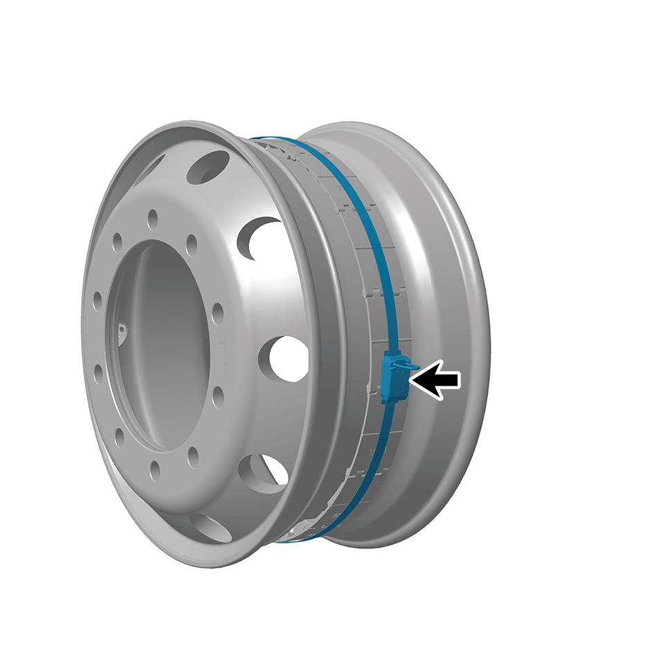
TESD.
Installation Procedures
1
Move the front tire pressure monitoring sensor and TESD
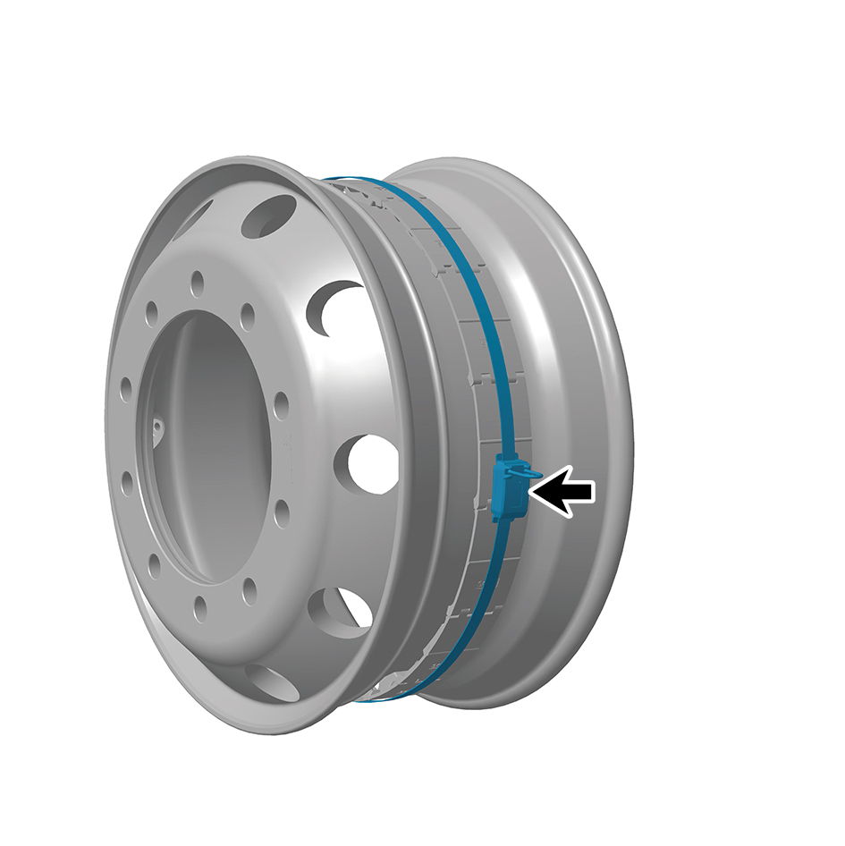
to the mounting position.
2
Install the tire assembly.
3
Install the guide wheel (right).
4
Lower the front end of the vehicle.
caution
After replacing the tire pressure monitoring sensor, it
is necessary to connect a scan tool for flashing and
recalibrate the tire pressure.
8.10.5.2 Replacement of Tire Pressure Repeater
Repeater
Removal Procedures
1
Open the door.
2
Open the front flip cover plate.
3
Disconnect the battery negative cable.
caution
power down the high-voltage system before
disconnecting the negative pole of the storage
battery.
4
Disconnect 1 harness connector of the tire pressure
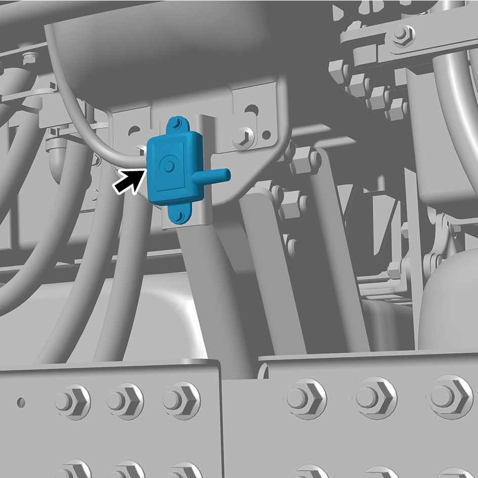
repeater.
5
Remove 2 fixing bolts of the tire pressure repeater.
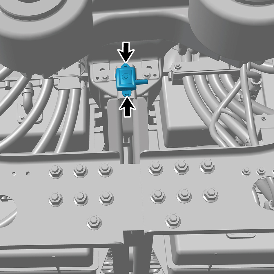
6
Remove the tire pressure repeater.
Installation Procedures
1
Move the tire pressure repeater to the mounting position.
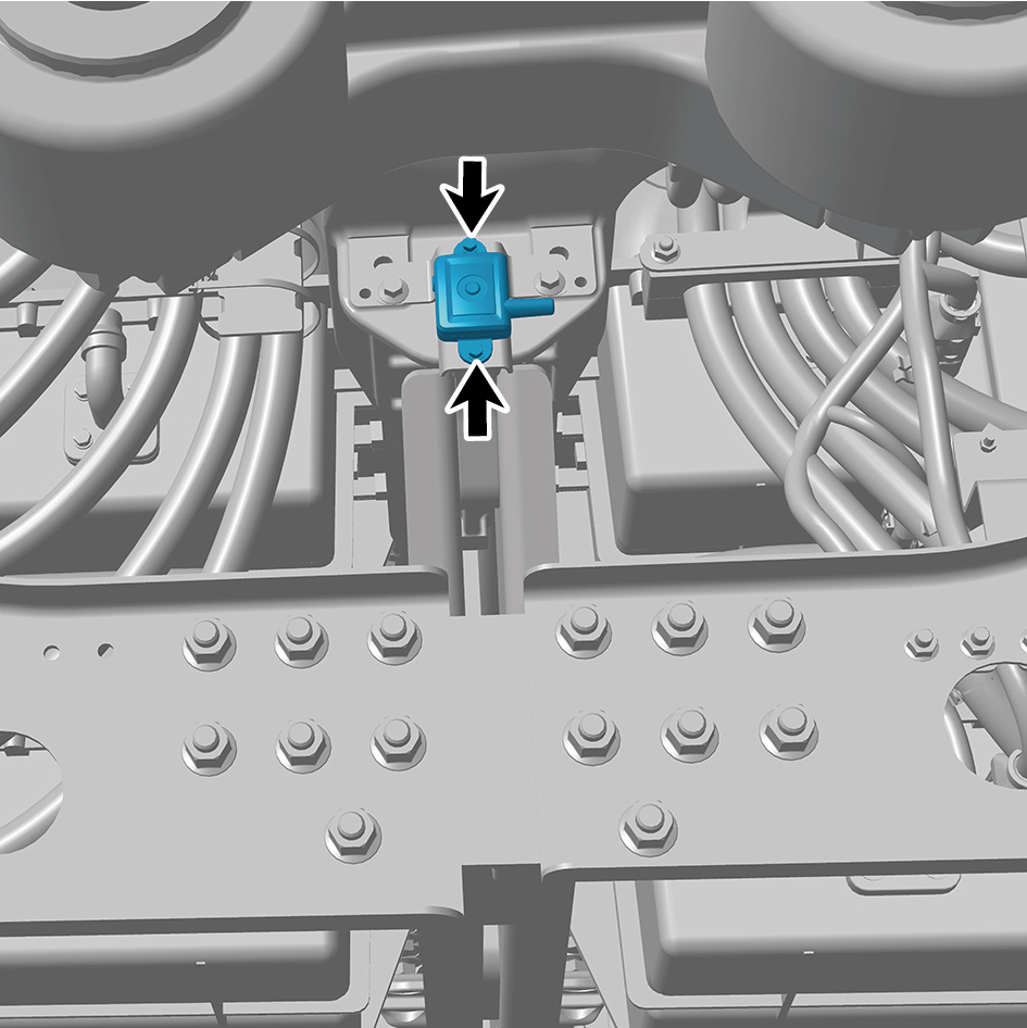
2
Install 2 fixing bolts of the tire pressure repeater.
Torque: (2 +/- .5) ft lbs
3
Connect 1 harness connector of the tire pressure
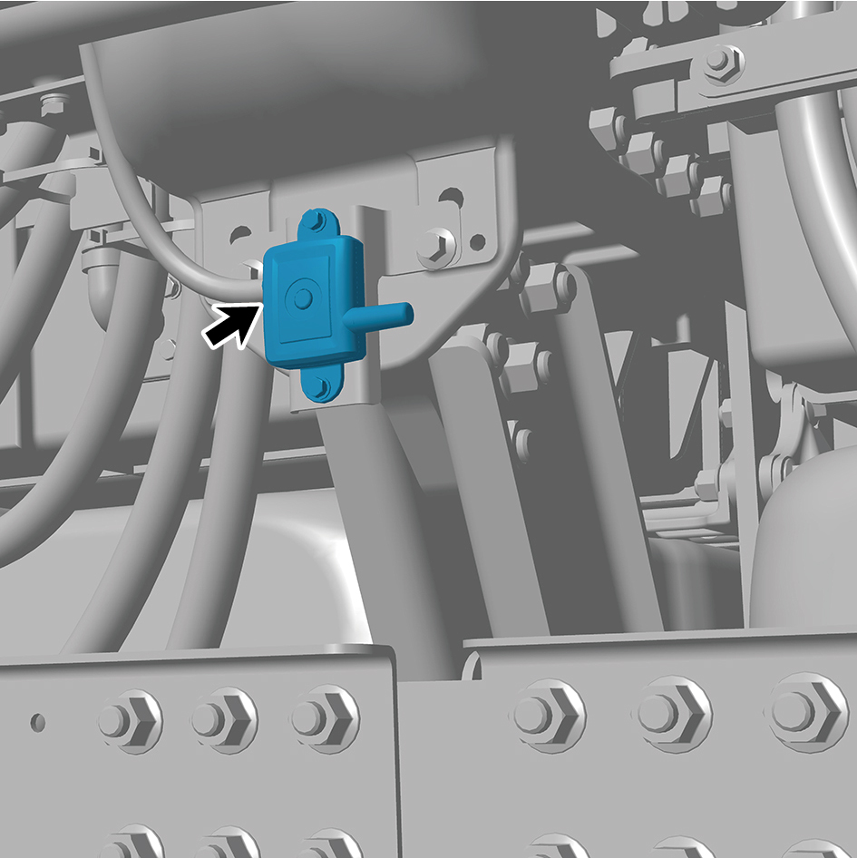
repeater.
caution
The harness is firmly connected following the
principal of "insert until a click is heard for
confirmation".
4
Connect the battery negative cable.
5
Close the front flip cover plate.
6
Close the door.
8.10.5.3 Replacement of Rear Tire Pressure Monitoring Sensor
Monitoring Sensor
Removal Procedures
1
Jack the rear end of the vehicle.
2
Remove the drive wheel (right front)
3
Remove the tire assembly.
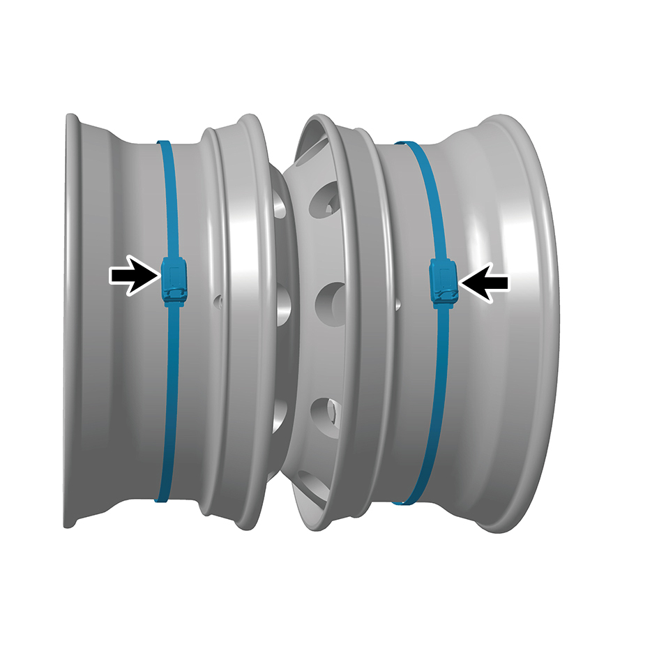
4
Remove the rear tire pressure monitoring sensor.
Installation Procedures
1
Move the rear tire pressure monitoring sensor to the
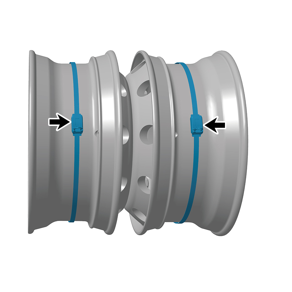
mounting position.
2
Install the tire assembly.
3
Install the drive wheel (right front).
4
Lower the rear end of the vehicle.
caution
After replacing the tire pressure monitoring sensor, it
is necessary to connect a scan tool for flashing and
recalibrate the tire pressure.
8.10.5.4 Replacement of Tire Pressure CAN Module
Module
Removal Procedures
1
Open the door.
2
Open the front flip cover plate.
3
Disconnect the battery negative cable.
caution
power down the high-voltage system before
disconnecting the negative pole of the storage
battery.
4
Jack the rear end of the vehicle.
5
Remove the drive wheel (front left).
6
Disconnect 1 harness connector of the tire pressure CAN
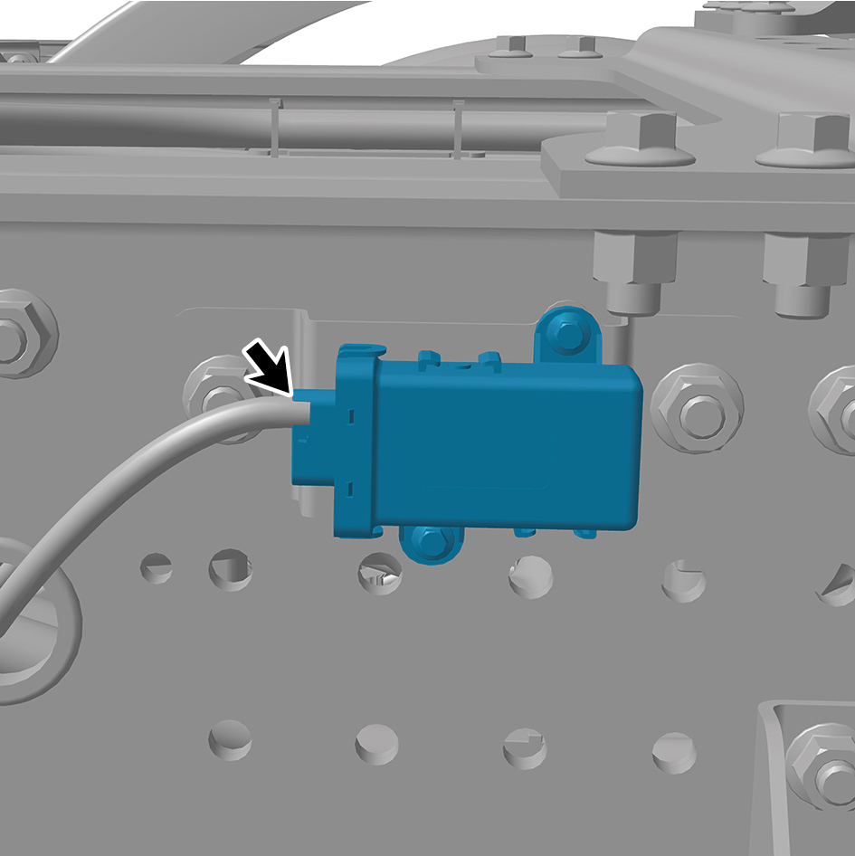
module.
7
Remove 2 fixing bolts of the tire pressure CAN module.
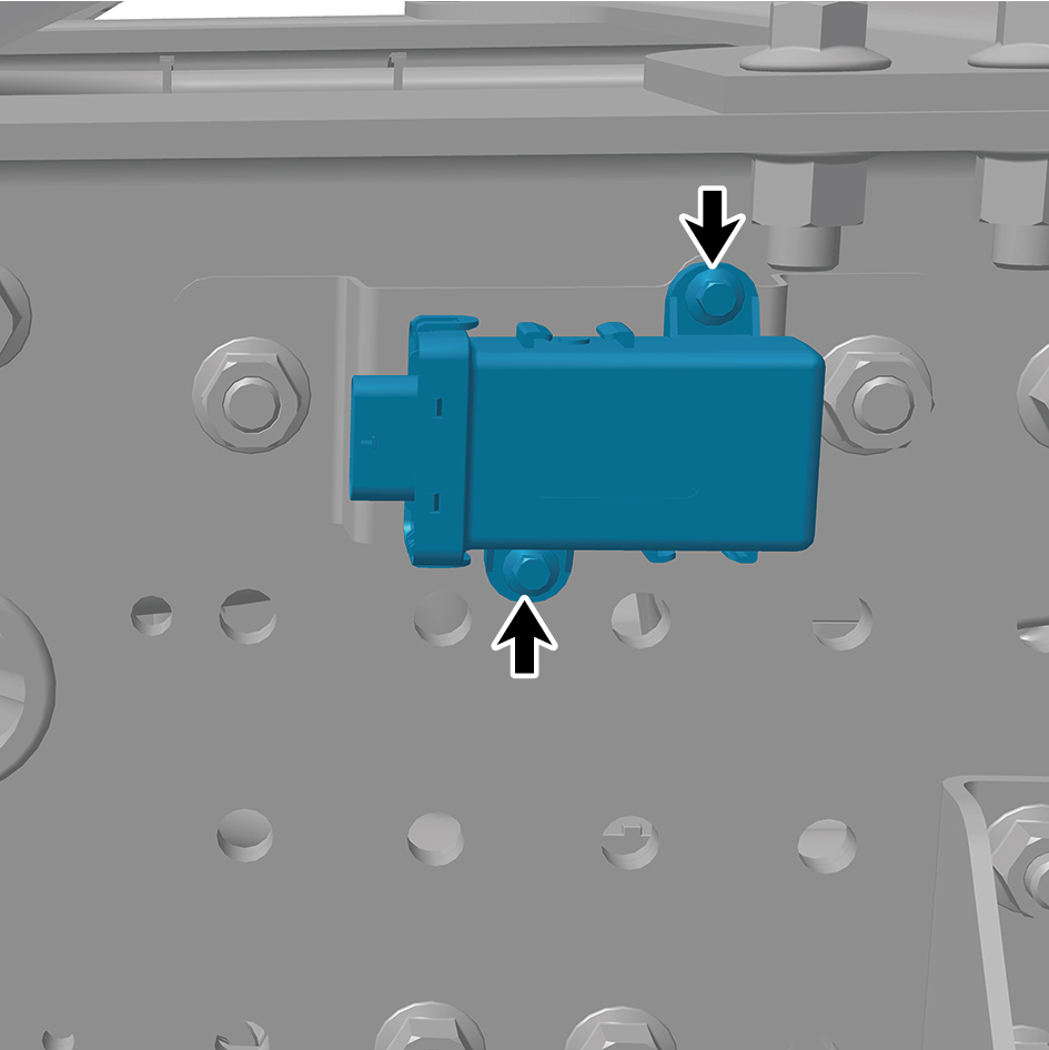
8
Remove the tire pressure CAN module.
Installation Procedures
1
Move the tire pressure CAN module to the mounting
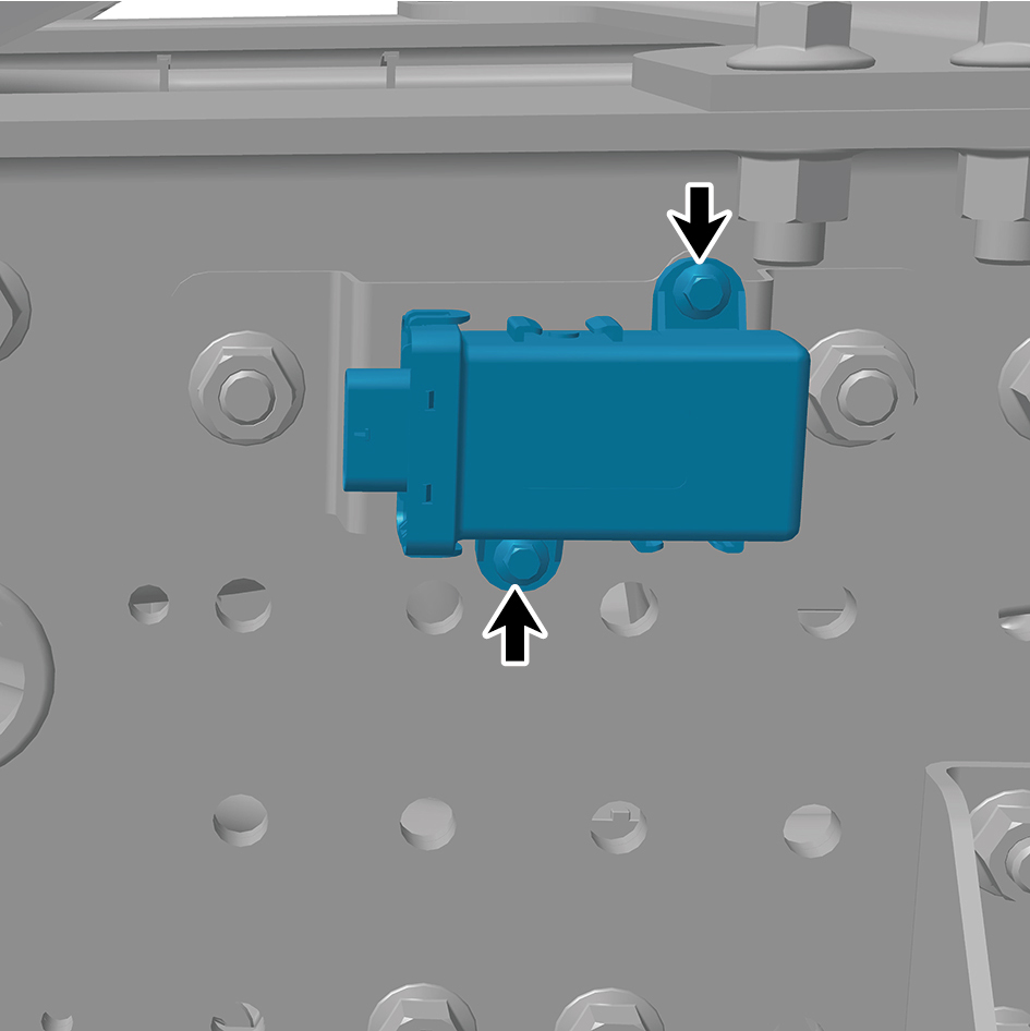
position.
2
Install 2 fixing bolts of the tire pressure CAN module.
Torque:(6.5 +/- .75) ft lbs
3
Connect 1 harness connector of the tire pressure CAN
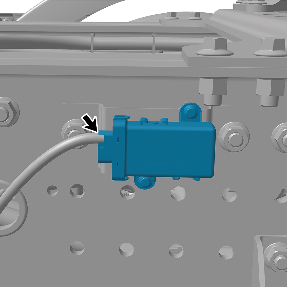
module.
caution
The harness is firmly connected following the
principal of "insert until a click is heard for
confirmation".
4
Install the drive wheel (left front).
5
Lower the rear end of the vehicle.
6
Connect the battery negative cable.
7
Close the front flip cover plate.
8
Close the door.