← Back to Contents
8 Chassis / 8.9 Wheel Device | PDF pages 2004-2014
8.9 Wheel Device
8.9 Wheel Device
8.9.1 Quality Warranty Statement
8.9.1.1 Tire Quality Warranty Statement
Windrose warrants that its vehicles are (1) designed, built and
equipped with tires that conform, at the time of sale, with
requirements of vehicle manufacturers whose vehicles are
designed to meet applicable 2014 and later, U.S.
Environmental Protection Agency and National Highway
Traffic and Safety Administration greenhouse gas and fuel
efficiency standards, and (2) those tires are free from defects
in material and workmanship which cause the vehicle to fail to
conform with the vehicle manufacturer’s requirements for a
period of 2 years or 24,000 miles, whichever occurs first.
8.9.2 Specifications
8.9.2.1 Fastener Specifications
Range Of Torque
Fastener Specifications
Specifications
Foot Pounds of Torque (ft lbs)
The fixing nut connecting the wheel hub
(479 +/- 37) ft lbs
M22
and the wheel rim
8.9.2.2 Technical Parameters
Four-wheel Alignment Parameters
Unit Adjustment
Item
Numerical Value
Kingpin inclination
°
7.9°±45′
Kingpin caster
°
2.5°±30′
Wheel camber
°
0.25°±45′
Front wheel toe-in
–1~2
Maximum internal rotation angle
°
42~45
Note: The camber and toe-in of the wheels are important parameters that shall be prioritized. The difference in left and right
angles shall be ≤0.5 °, and the toe-in of the left and right wheels shall be ensured.
Driving Tire Model
Item
Axle
Form 1
Form 2
Form 3
Input shaft
12R22.5
295/80R22.5
315/70R22.5 Z2
Tire specifications
Output shaft
12R22.5
295/80R22.5
315/70R22.5 D2
3rd shaft
12R22.5
295/80R22.5
315/70R22.5 D2
Wheel Rim Model
Item
Form 1
Form 2
Form 3
Rim specifications
9.00×22.5
9.00×22.5
9.00×22.5
Tire Dynamic Unbalance
Unit Adjustment
Item
Wheel Rim Form 1
Wheel Rim Form 2
Dynamic unbalance
≤50 (after balance)
≤50 (after balance)
Tire Pressure (cold state)
Wheel
Unit
Form 1
Form 2
Form 3
psi
135 +/- 3 (psi)
135 +/- 3 (psi)
135 +/- 3 (psi)
Front wheels
psi
135 +/- 3 (psi)
135 +/- 3 (psi)
135 +/- 3 (psi)
Rear wheels
Name
Parameter
≤0.5mm
Wheel radial runout
≤0.1mm
Wheel face flatness
8.9.3 Decomposition Diagram
8.9.3.1 Decomposition Diagram
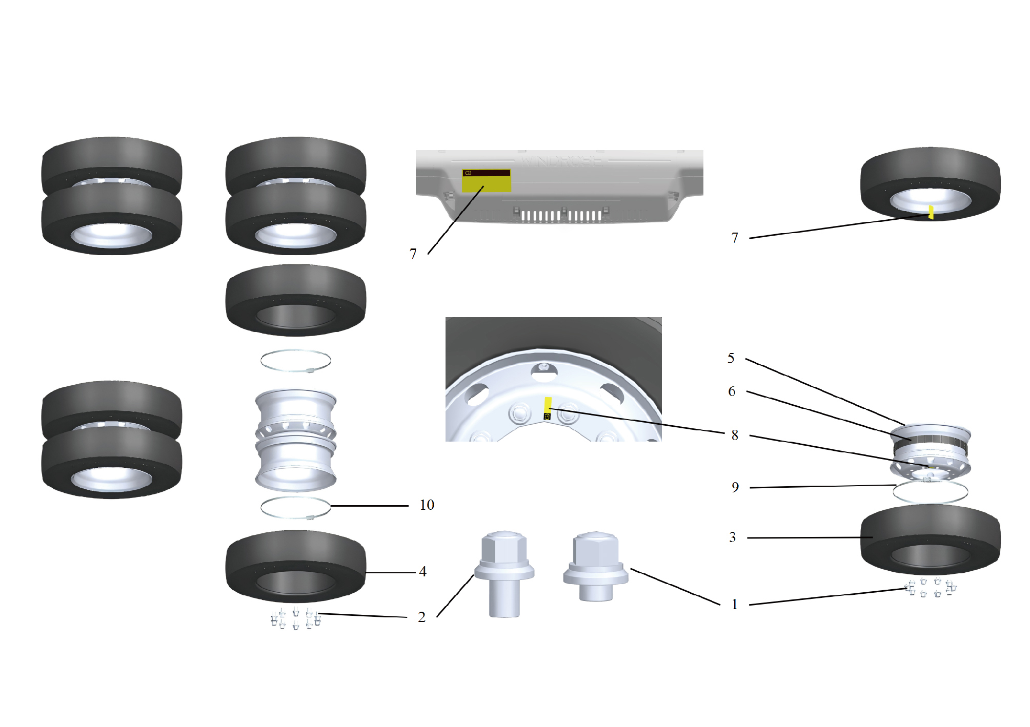
1.
6.
Wheel Nut (Front) In New Energy Vehicles
Tyre Blowout Emergency Safety Device In New Energy
Vehicles
7.
2.
Wheel Nut (rear) In New Energy Vehicles
Tyre Blowout Emergency Identification (Indoor) In New
Energy Vehicles
3.
8.
Tyre Blowout Emergency Identification (wheel side) In
Tire Assembly - Guide Wheel
New Energy Vehicles
4.
9.
Tire Assembly - Drive Wheel
Front Tire Pressure Monitoring Sensor
5.
Wheel Assembly In New Energy Vehicles
10.
Rear Tire Pressure Monitoring Front Tire Pressure
Monitoring Sensor
8.9.4 Inspect
steerable wheel (front wheel), new tires must be used and it is
never allowed to replace tires with worn old tires.
8.9.4.1 Inspection of Tire
Tire Usage
Inspection of Air Pressure
1. Limiting driving speed
The tire pressure shall comply with the specified value in the
The increased driving speed, especially frequent high-speed
user manual. Regularly check the tire pressure, as high or low
driving, significantly reduces the service life of tires.
pressure can cause abnormal tire wear. If the air pressure is
too high, it will cause excessive wear in the middle of the tire;
2. Driving according to road conditions
If the air pressure is too low, it will cause excessive wear on
The type and condition of road surface have a significant
both sides of the tire. In addition, incorrect tire pressure can
impact on the service life of tires. The driver shall choose the
also cause reduced ride comfort, heavy steering, braking
road surface according to the road conditions and select the
deviation, and other faults.
appropriate driving speed to increase the mileage of tires.
Inspection of Crack and Pattern
3. Mastering tire temperature changes
Regularly inspect the surface of the tire for defects such as
a. When driving in hot weather, due to the high external
cracks and deformations, and if any, replace the tire promptly.
temperature, the accumulated heat in the tires is difficult to
Regularly inspect the surface of the tire for defects such as
dissipate, causing a sharp rise in tire temperature and an
cracks and deformations, and if any, replace the tire promptly.
increase in tire pressure, thereby accelerating rubber aging.
Tire with the pattern wear reaching the height of the TWI (the
Therefore, when driving in hot weather, attention shall be paid
depth of the tire pattern must not be less than 1.6 mm) must
to controlling the temperature of the tires. In addition to
be replaced.
appropriately reducing the vehicle speed, if conditions permit,
Lifespan Inspection and Rotation
driving can be done in the morning and evening when the
Tires that have been in use for more than 5 years must be
temperature is low, or after driving a certain distance, stopping
replaced by force.
and resting to prevent tire temperature from being too high.
Inspection of Tire Tread
b. It is prohibited to deflate to reduce pressure. In the season
of low temperature, as tires dissipate heat faster during use,
Regularly check the tire tread is punctured and whether there
they are less prone to high heat, and the tread is more wear-
are any stones stuck between the two wheels. Remove the
resistant. In seasons with low temperatures, especially in
stones embedded in the tire. If small holes are found on the
severe cold weather, it is advisable to drive at low speeds for
tread, they shall be filled with rubber to prevent sand and mud
the first few kilometers after starting in order to increase tire
from entering the cord layer and causing voids.
temperature when the vehicle is parked overnight or after a
Vehicle Parking
long period of time. In short, mastering tire temperature
When parking the vehicle, it is also important to protect the
changes during driving is extremely important.
tires and avoid parking on roads with large, sharp, or sharp
4. Adopting the correct driving method
obstacles. In addition, it is advisable to avoid contact between
passenger cars and petroleum products, acidic substances,
The car shall not start too aggressively, and both empty and
and other materials that may affect rubber deterioration.
heavy vehicles shall start smoothly at low speed. Avoid
dragging the tires on the ground to reduce tread wear.
Handling of Overheating
When driving on a good road surface, keep moving in a
Tires are prone to overheating and increased air pressure
straight line, and avoid swaying left and right or making sharp
during summer or high-speed driving. In this case, the vehicle
turns, except when meeting vehicles or avoiding obstacles, to
shall be parked to dissipate heat, and deflation, pressure
prevent lateral cutting between the tire and the wheel rim from
reduction, or water splashing to cool down are strictly
damaging the tire.
prohibited.
When the vehicle goes down a long slope, the vehicle speed
Tire Replacement
shall be appropriately controlled according to the slope size,
When installing tires, tires of the same specification, size,
length, and road conditions. In situations where the slope is
pattern, and number of cord layers shall be installed on the
long, the road is steep, and the road conditions are complex, it
same axle. When replacing tires, it is best to replace all tires
is advisable to shift into low gear and use light braking to
at the same time, at least in pairs. For the replacement of the
control the vehicle speed downhill. This not only avoids
When parking on the way or on site, it is important to develop
emergency braking and reduces tire wear, but also ensures
a habit of safe sliding when parking. Before parking, choose a
safe driving.
flat, clean, and oil-free ground. Each tire shall land smoothly,
especially if the vehicle is loaded overnight, attention shall be
When the vehicle is going uphill, try to use inertia to drive,
paid to choosing a good parking place, and the rear wheel
change gears at the right time, maintain appropriate residual
shall be lifted if necessary.
force, and do not wait for the car to stop before restarting to
8.9.4.2 Four-wheel Alignment
reduce tire wear.
When turning while driving, the vehicle speed shall be
1. Jack the vehicle.
controlled according to the situation of the curve. Do not turn
2. Check the tires.
at high speed, otherwise the vehicle will generate a large
3. Check the front suspension.
centrifugal force, causing the loaded cargo to tilt, the center of
mass to shift to one side, and the single-sided tire to be
caution
overloaded and dragged, accelerating wear, and the tire to be
Check the suspension for wear, looseness,
cut horizontally by the wheel rim, causing damage.
deformation, and damage. In case of any of the
When driving in complex situations (such as meeting,
above defects, adjust, tighten, or replace accordingly.
overtaking, passing through towns, intersections, and
4. Check the steering angle of the wheels.
crossing railways), it is important to maintain an appropriate
caution
driving speed, reduce frequent braking, and avoid emergency
braking. Otherwise, sliding friction between the tire and the
If the measured value is not within the specified
ground will occur, resulting in severe wear of the tread.
range, the steering tie rod needs to be checked.
On bad roads, slow down and observe carefully, choose a
5. Loosen the fixing bolts of the upper and lower swing arms,
path to pass through, and stop to check if there are stones
and add shims between the ball joint and the subframe to
between the twin tires. If there are, they shall be removed in a
change the value of the camber angle.
timely manner.
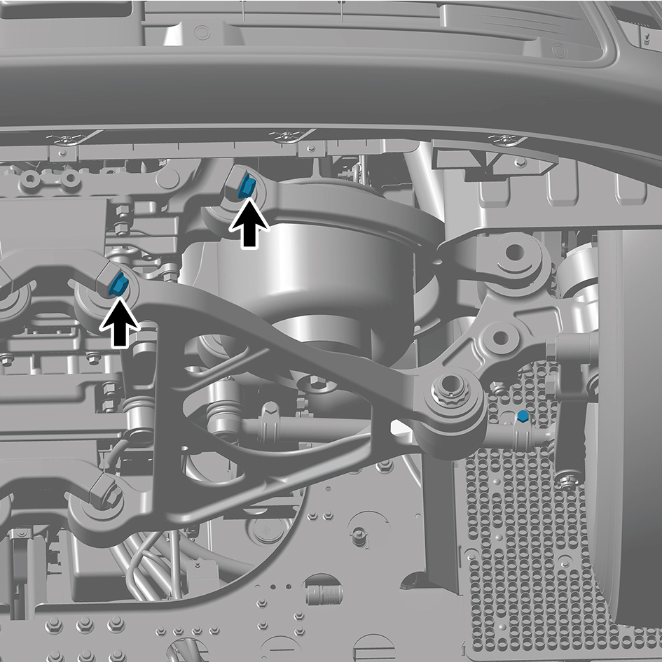
6. Tighten the fixing bolts of the upper and lower swing arms.
direction of the toe in change, and determine the
adjustment value.
7. Loosen the adjustment bolt of the steering rod, adjust the
length of the rod by rotating the ball joint, observe the
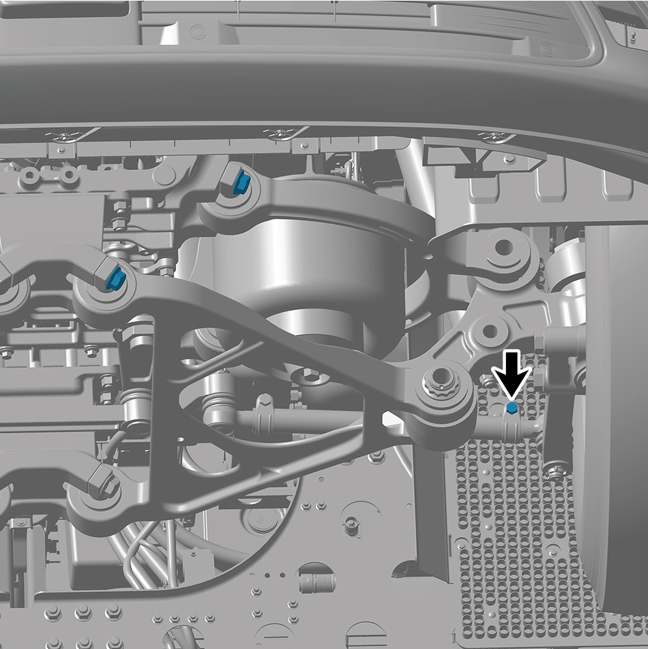
caution
1. When performing brake checks on tires according to the
prescribed maintenance schedule, it is recommended to
1. After adjustment, the difference in length between
perform tire cross rotation.
the left and right tie rods shall be ≤2mm;
2. Jack the vehicle.
2. After adjustment, fix the inner clamp bolt above the
caution
rod.
Record the original position of each tire and wheel
8. Tighten the adjustment bolt of the steering rod.
assembly relative to the vehicle.
9. Lower the vehicle.
3. Remove the wheel assembly.
8.9.4.3 Tire Rotation
4. Perform rotation to the tire and wheel assembly according
caution
to the following diagram.
If there is obvious uneven tire wear, the cause of this
wear shall be ruled out.
In case of tire rotation, it is recommended to check the
balance of both the tire and wheel assemblies
simultaneously.
caution
Perform tire cross rotation as shown below.
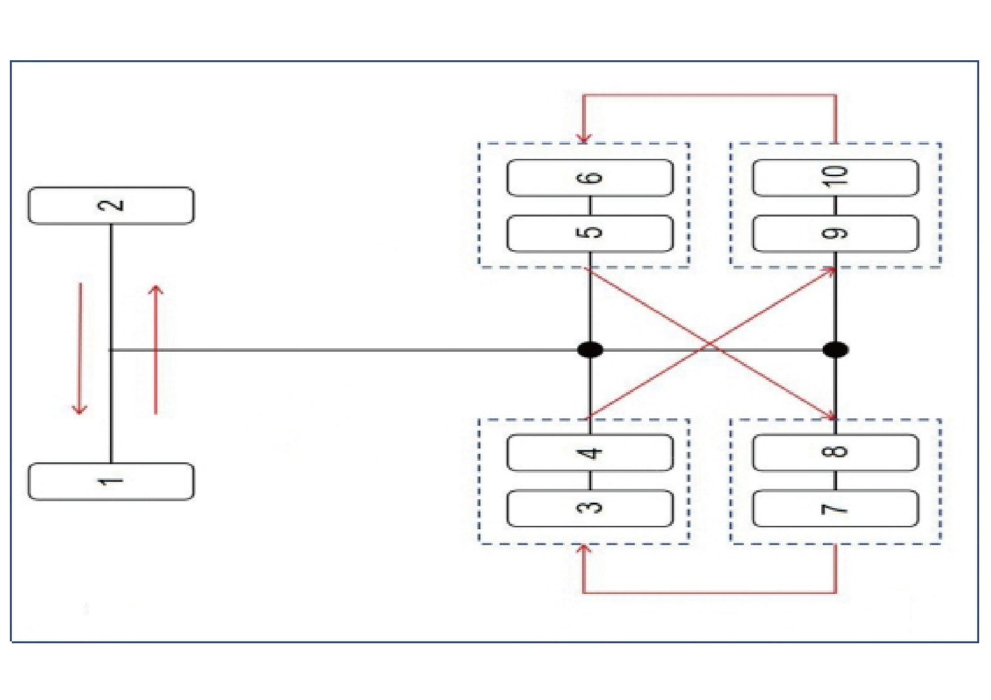
caution
1. The front axle tires shall not be interchanged with
the intermediate and rear axle tires;
2. If there Is a rotation direction on the tire, and after
tire rotation,make sure that the direction of rotation is
the forward direction of the vehicle;
3. After the tire rotation is completed, recalibrate the
tire pressure for all tires.
5. Install the wheel assembly.
6. Lower the vehicle.
7. Check and adjust the tire inflation pressure.
8.9.5 Dismantling and Installation
8.9.5.1 Replacement of Tire Assembly
Removal Procedures
1
Jack the front end of the vehicle.
2
Remove the guide wheel.
3
Release the air from the tire and use a pry bar to pry off
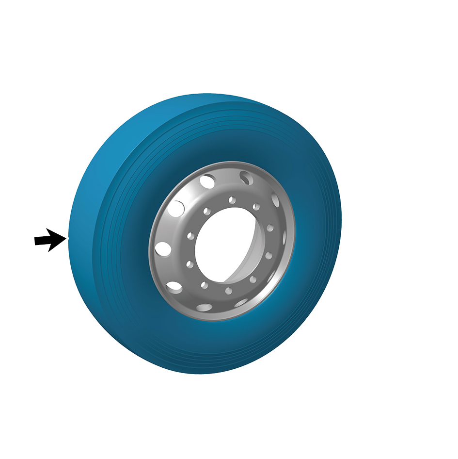
the tire.
4
Remove the tire assembly.
caution
Due to the heavy weight of the tire, it shall be
removed with the help of an assistant.
Installation Procedures
1
Move the tire assembly to the mounting position.
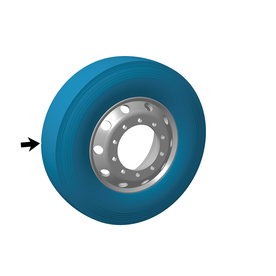
caution
Due to the heavy weight of the tire, it shall be moved
to the mounting position with the help of an
assistant.
2
Measure the tire pressure on both sides with a pressure
gauge to ensure that the tire pressure remains consistent.
3
Perform tire dynamic balancing.
4
Install the guide wheel.
5
Lower the front end of the vehicle.
8.9.5.2 Replacement of TESD
Removal Procedures
1
Jack the front end of the vehicle.
2
Remove the driven wheel.
3
Deflate the tyre and then separate the tyre from the rim,
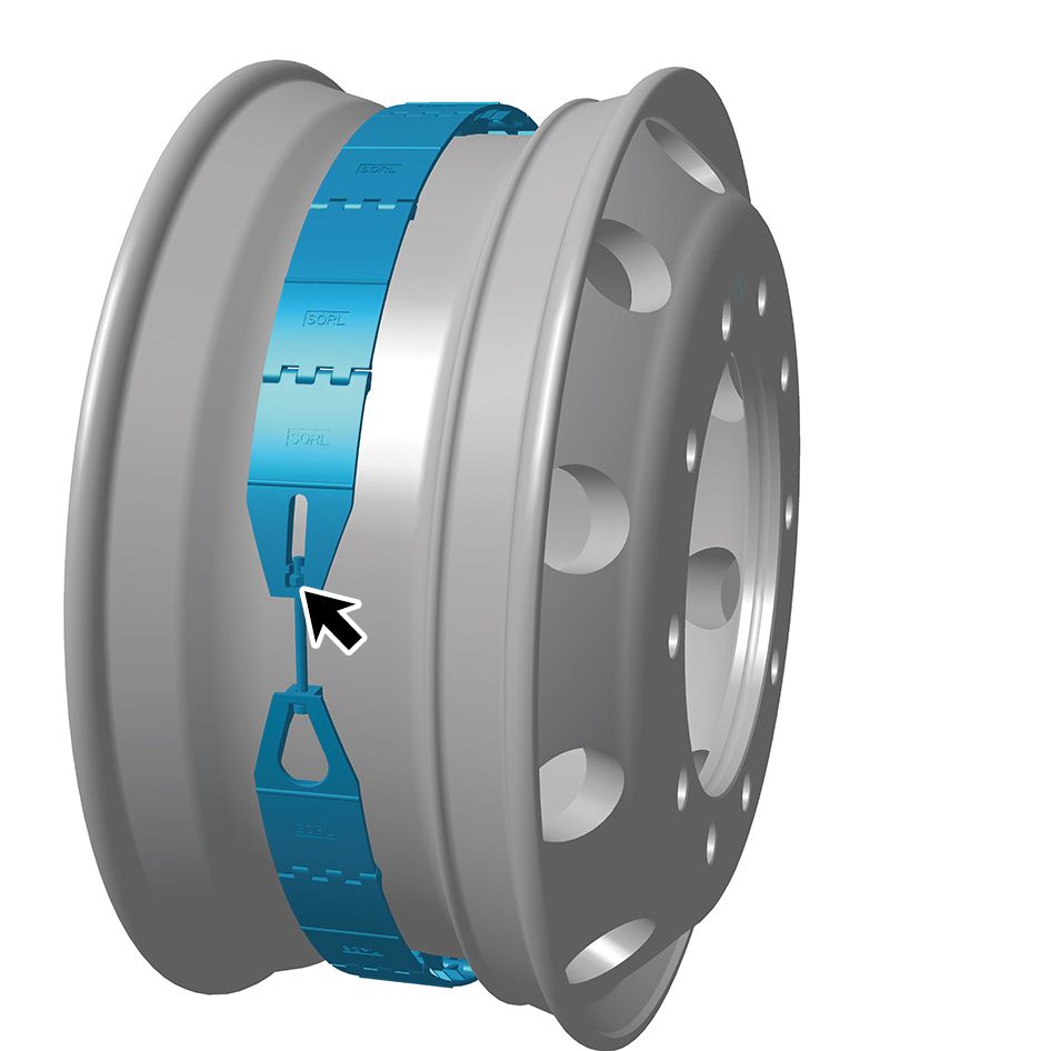
and remove the TESD.
caution
Do not damage the wheels during removal.
Installation Procedures
1
Install the TESD and inflate the tyre assembly after pre-
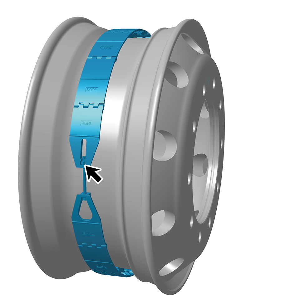
installation.
Torque: (7.5 - ft lbs)
2
Install the driven wheel.
3
Lower the front end of the vehicle.
8.9.5.3 Replacement of Wheel Assembly
Removal Procedures
caution
The removal and installation procedure for all tires is
the same.
To maintain wheel balance, mark the relative
position of the wheels before removing the tires.
1
When removing the wheel assembly, first loosen the 10
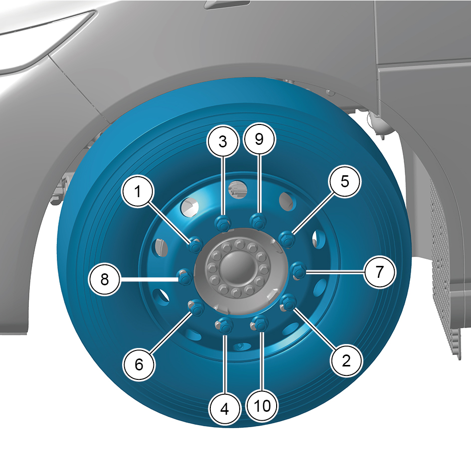
wheel nuts that connect the wheel assembly to the outer
flange connection plate assembly, and then use a jack.
2
Put the jack on the front axle assembly and tighten the
control valve clockwise to fix the jack.
3
Insert the jack rocker into jack sleeve to lift the vehicle.
caution
1. The jack must be used on a hard bearing surface
and must be supported on the plane position of the
vehicle jacking point. It is prohibited to use the jack
on an inclined plane with an inclination angle greater
than 6° to avoid violent vibration or sliding of the
jack.
2. Use the jack within its load limit to avoid
abnormalities such as failure caused by overload.
After the vehicle is lifted, support the vehicle with
solid objects of equal height in the area around to
avoid personal injury caused by jack failure. When
unloading the jack, open the control valve slightly to
allow the jack to drop slowly to avoid slipping or
damage due to the jack dropping too fast. Besides,
the sudden drop of the vehicle will also threaten
personal safety.
4
When the wheel assembly is off the ground, unscrew the
10 wheel nuts that connect the wheel assembly to the
outer flange connection plate assembly.
caution
Tighten in the order of diagonal 1 to 10.
5
Remove the wheel assembly.
Installation Procedures
1
Move the wheel assembly to the mounting position.
caution
1. When replacing the tires, the tires on the same
axle shall be replaced at the same time.
2. The inner and outer valves shall be staggered to
facilitate the tire inflation.
2
Lubricate the threaded surface of the nuts with engine oil,
gear oil or grease to achieve a slight degree of wetting.
caution
1. Do not use lubricants containing molybdenum
disulfide, organic molybdenum, or other
molybdenum additives to avoid corrosion of the tire.
2. Do not apply oil to the tire rims and axle end
surfaces that contact with bolts and nuts.
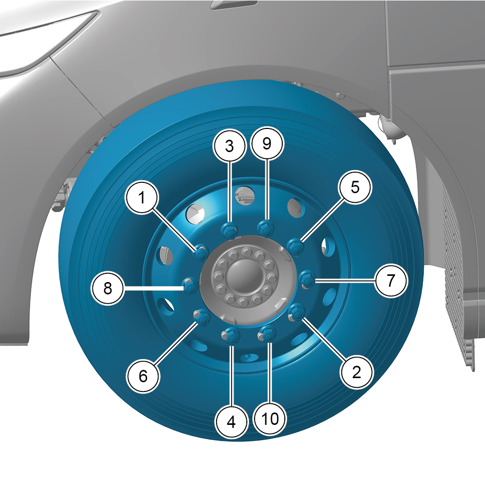
3
Tighten the 10 wheel nuts that connect the wheel
assembly to the outer flange connection plate assembly,
release the jack and lower the vehicle, then tighten the
nuts diagonally again.
Torque: (479 +/- 37) ft lbs
4
After the wheel touches the ground, turn the tire half a
circle and tighten the 10 wheel nuts of the wheel assembly
again.
Torque:(479 +/- 37) ft lbs
caution
After replacing the tire, conduct an initial test run,
and tighten again to the specified torque after
driving 30-60 miles.