← Back to Contents
8 Chassis / 8.8 ECU Actuator of Air Suspension | PDF pages 1956-2003
8.8 ECU Actuator of Air Suspension
8.8 ECU Actuator of Air Suspension
8.8.1 Specifications
8.8.1.1 Fastener Specifications
Range Of Torque
Fastener Specifications
Specifications
Foot Pounds of Torque (ft lbs)
The fixing bolt connecting the airbag
solenoid valve bracket to the frame
103 +/- 7.5 (ft lbs)
M14
assembly
The fixing bolt connecting the height
103 +/- 7.5 (ft lbs)
M14
sensor bracket to the frame assembly
The fixing bolt connecting the airbag
18.5 +/- 2 (ft lbs)
M8
solenoid valve assembly to the airbag
solenoid valve bracket
The fixing bolt connecting the airbag
solenoid va The fixing bolt connecting
the height sensor assembly and the
18.5 +/- 2 (ft lbs)
M8
height sensor bracketlve assembly to
the airbag solenoid valve bracket
The fixing bolt connecting the remote
control assembly and the white body
8 +/- .75 (ft lbs)
M6
assembly assembly
The fixing bolt connecting the remote
control bracket to the right storage box
8 +/- .75 (ft lbs)
M6
assembly
The fixing bolt connecting the height
8 +/- .75 (ft lbs)
M6
sensor assembly and the swing rod
NG8 nut seat on airbag solenoid valve
7.5 - 12 (ft lbs)
M16
tracheal interface
NG8 nut seat on the air spring assembly
7.5 - 12 (ft lbs)
M16
air pipe interface
Pressure sensor on the air spring
18.5 +/- 2 (ft lbs)
M16
assembly air pipe interface
The fixing bolts connecting the air
8 +/- .75 (ft lbs)
M6
suspension controller assembly to the
floor sheet metal
The direct head connecting the airbag
solenoid valve assembly and the
7.5 - 12 (ft lbs)
M22
overflow valve assembly
8.8.2 Decomposition Diagram
8.8.2.1 Decomposition Diagram
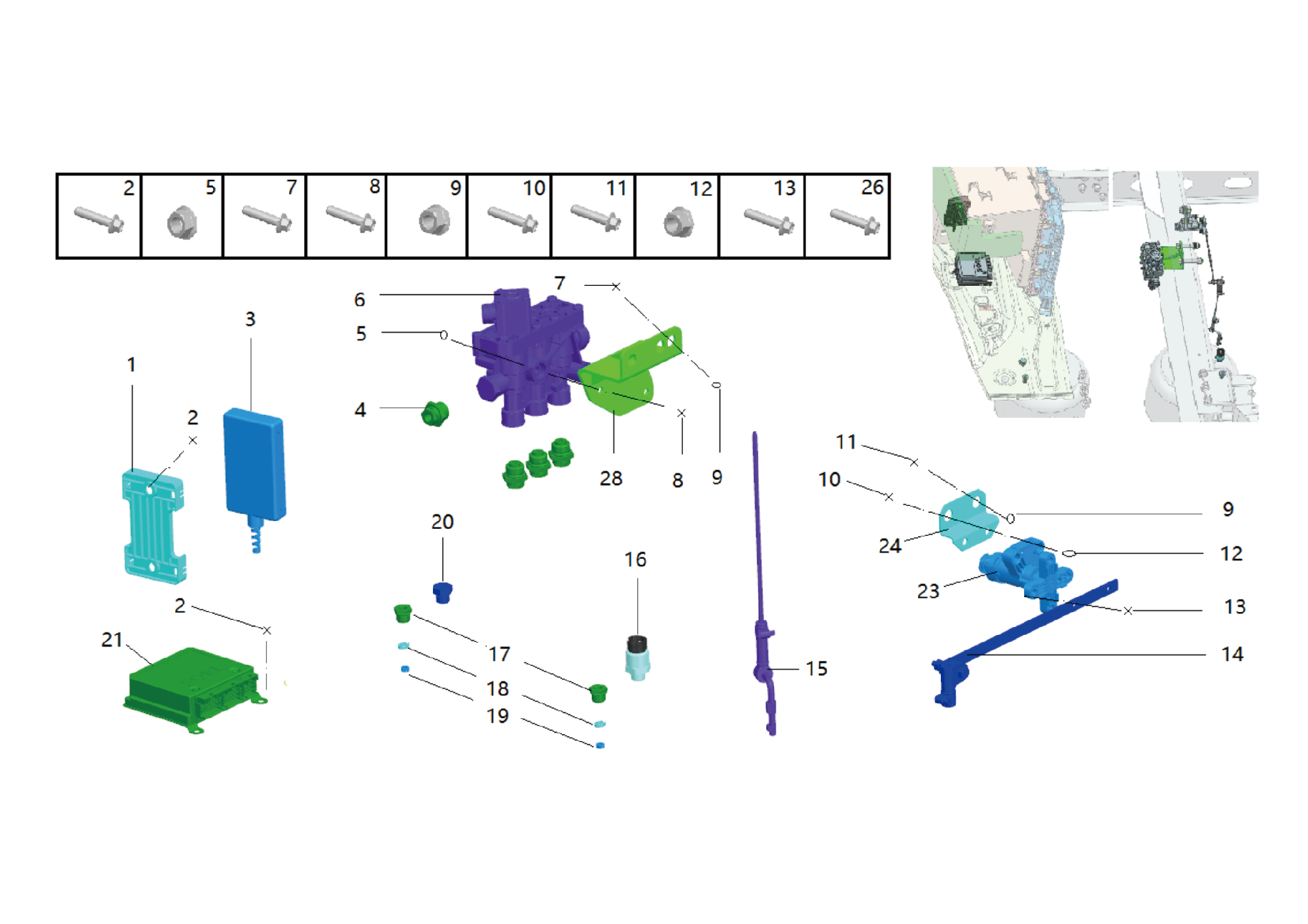
1.
14.
Pendulum Bar
Remote Control Stand
2.
15.
Hexagon Flange Bolt
Connecting Rod
3.
16.
Remote Control Assy
Pressure Sensor Assy
4.
17.
Direct Head
Nut Seat NG8
5.
Hexagon Nut_Type 1
18.
Snap Ring NG8
6.
19.
Washer Ng8
Airbag Solenoid Valve Assy
7.
Hexagon Flange Bolt
20.
Plug
8.
Hexagon Flange Bolt
21.
Air Suspension Controller Assy
9.
Hexagon Flange Lock Nut_All Metal
23.
Height Sensor Assy
10.
Hexagon Flange Bolt
24.
Distance Sensor Bracket
11.
Hexagon Flange Bolt
26.
Hexagon Flange Bolt
12.
28.
Hexagon Flange Lock Nut_All Metal
Brkt-Air Bag Solenoid Valve
13.
Hexagon Flange Bolt
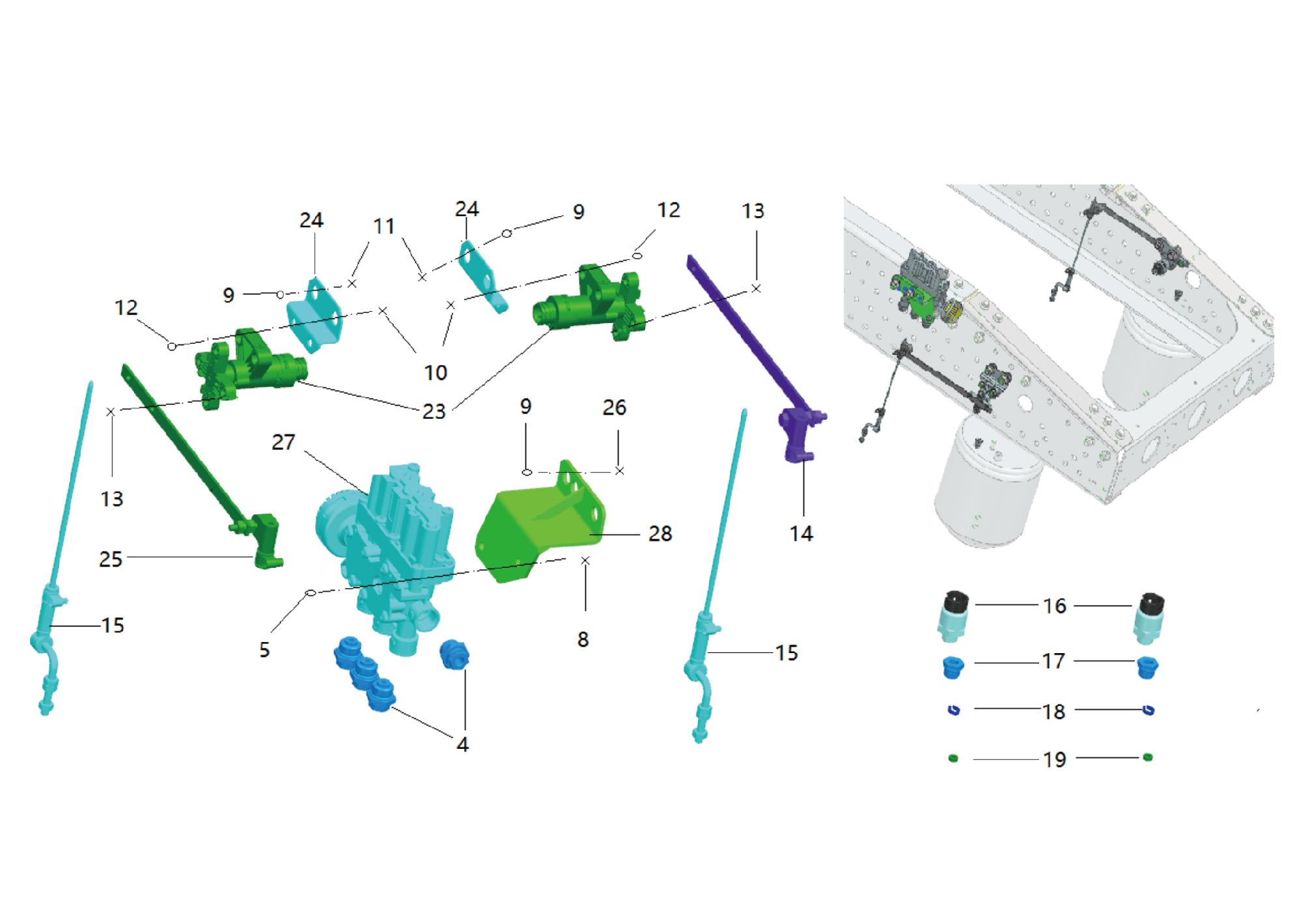
4.
Direct Head
16.
Pressure Sensor Assy
5.
Hexagon Nut_Type 1
17.
Nut Seat NG8
8.
Hexagon Flange Bolt
18.
Snap Ring NG8
9.
Hexagon Flange Lock Nut_All Metal
19.
Washer Ng8
10.
Hexagon Flange Bolt
24.
Distance Sensor Bracket
11.
Hexagon Flange Bolt
25.
Pendulum Bar
12
Hexagon Flange Lock Nut_All Metal
26.
Hexagon Flange Bolt
13.
Hexagon Flange Bolt
27.
Airbag Solenoid Valve Assy
14.
28.
Pendulum Bar
Brkt-Air Bag Solenoid Valve
15.
Connecting Rod
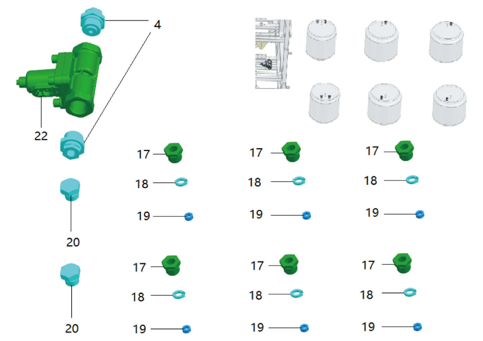
4.
Direct Head
19.
Washer Ng8
17.
20.
Plug
Nut Seat NG8
18.
22.
Snap Ring NG8
Solenoid Modulator Valve Assy
8.8.3 System Schematic Diagram
8.8.3.1 Electrical Schematic Diagram
8.8.4 Diagnostic Information and Steps
8.8.4.1 Diagnostic Description
Before diagnosing the malfunction of the air suspension electronic control unit actuator, it is important to understand and
familiarize oneself with the working principle of the air suspension electronic control unit actuator before starting the system
diagnosis. This will help determine the correct fault diagnosis steps when a malfunction occurs, and more importantly, it will help
determine the situation described by the customer belongs to normal operation. Any fault diagnosis of the air suspension
electronic control unit execution device should start with routine inspection, guiding maintenance personnel to take the next
logical step for fault diagnosis. Understanding and correctly using the diagnostic process can shorten the diagnosis time and
avoid misjudgment of faulty parts.
8.8.4.2 Routine Inspection
• Check for aftermarket devices that may affect the operation of the air suspension electronic control unit execution device
system, ensuring that these devices do not affect the operation of the air suspension electronic control unit execution device
system.
• Check system components that are easily accessible or visible to ensure that there is no obvious damage or potential
malfunction.
8.8.4.3 DTC Confirmation
1. Connect the diagnostic tool to the diagnostic interface, read and record the DTC, and then clear the DTC.
2. Run the vehicle again.
3. Read the fault code of the control system again to confirm if there is any fault code output from the system.
– Yes:Diagnose based on the output fault code.
– No:Perform intermittent fault check, refer to Inspection Of Intermittent Faults
8.8.4.4 List Of Diagnostic Trouble Codes (DTC)
ECAS
Fault Description
Exclusion Method
Fault Code
Over-voltage
U152017
Refer to ECAS Power Fault
Under-voltage
U152016
U15CD08
CCVS Communication Timeout
U15D408
TCO1 Communication Timeout
Refer to ECAS Communication Fault
U15DB08
ASC2 Communication Timeout
U15CE08
AIR1 Communication Timeout
ECU general memory failure
C12FE42
Refer to ECAS Internal Fault
VFF power failure
C12FE49
Front height sensor short to gnd
C121011
Front height sensor short to battery
Refer to Front Axle Height Sensor Fault
C121015
Front height sensor out of range
C121014
Rear left height sensor short to gnd
C121311
Refer to Rear Axle Left Height Sensor
Rear left height sensor short to battery
C121315
Fault
Rear left height sensor out of range
C121314
Rear right height sensor short to gnd
C121211
Refer to Rear Axle Right Height Sensor
Rear right height sensor short to battery
C121215
Fault
Rear right height sensor out of range
C121214
Fault Description
Exclusion Method
Fault Code
Front pressure sensor short to gnd
C121611
Refer to Front Axle Pressure Sensor
Front pressure sensor short to vcc
C121612
Fault
Front pressure Sensor open
C121613
Rear Left pressure sensor short to gnd
C121911
Refer to Left Rear Axle Pressure Sensor
Rear Left pressure sensor short to vcc
C121912
Fault
Rear Left pressure Sensor open
C121913
Rear Right pressure sensor short to
C121811
gnd
Refer to Right Rear Axle Pressure
Rear Right pressure sensor short to vcc
Sensor Fault
C121812
Rear Right pressure sensor open
C121813
Front solenoid vavle short to gnd
C120111
Refer to Front Axle Suspension
Front solenoid vavle short to vcc
C120112
Solenoid Valve Fault
Front solenoid vavle open
C120113
Rear left solenoid vavle short to gnd
C120411
C120412
Rear left solenoid vavle short to vcc
Rear left solenoid vavle open
C120413
Rear central solenoid vavle short to gnd
C120711
Refer to Rear Axle Suspension Solenoid
Rear central solenoid vavle short to vcc
C120712
Valve Fault
Rear central solenoid vavle open
C120713
Rear right solenoid vavle short to gnd
C120311
Rear right solenoid vavle short to vcc
C120312
Rear right solenoid vavle open
C120313
Pressure power failure
C122E94
Refer to Pressure Sensor Power Fault
solenoid valve power short to vcc
C122212
Refer to Suspension Solenoid Valve
Power Fault
solenoid valve power short to gnd
C122211
RCU power short circuit
C122F12
Refer to Remote Control Fault
RCU control signal not issued
C123013
8.8.4.5 ECAS Power Fault
1. DTC Monitoring Logic
DTC Detection Conditions (Control
Faulty Part
Description
DTC Trigger Conditions
DTC Code
Strategy)
1. Main
Over-voltage
Over-voltage Timeout 2s
Ignition ON
U152017
battery
2. Low
voltage
charging
Under-voltage
Under-voltage Timeout 2s
Ignition ON
U152016
system
3. Wiring
harness
4.ECAS
2.Circuit Diagram
Smart Junction
Smart Junction Box - Body
Box - Chassis
Battery
B12-1
B07-3
B01-1
B07-2
Total body power
supply B+ L22
Chassis CAN8
KL15 Power
supply P102
ECAS Power supply KL30 P103
Chassis CAN8-H TH08b
Chassis CAN8-L TL08b
ECAS Power supply
KL15 P102m
B58-7
B58-3
B58-1
B58-10
ECAS X1
B58-12
B58-8
B58-11
B58-15
B58-13
Remote control power supply U813
Remote control grounding U815
EECAS grounding Z10
Remote control CLOCK U808
Remote control DATA U811
G29
B59-3
B59-1
B59-4
B59-2
Remote control unit
3. Diagnostic Steps
Step 1:DTC confirmation. Refer to DTC Confirmation
Step 2:Routine inspection. Refer to Routine Inspection
Step 3:Check if there are any other module power fault codes besides ECAS?
Check the main battery. Refer to Inspection Of The Main Battery
– Yes:
Check the low-voltage charging system. Refer to DCDC1 Low-voltage Charging System Fault
Next step
– No:
Step 4:Check the ECAS power and grounding harness.
Step 5:ECAS rewrites configuration codes, reloads software, and upgrades.
Step 6:Replace ECAS. Refer to Replacement Of Air Suspension Controller Assembly
Step 7:Clear and confirm DTC.
8.8.4.6 ECAS Communication Fault
1. DTC Monitoring Logic
DTC Detection Conditions (Control
Description
DTC Trigger Conditions
Faulty Part
DTC Code
Strategy)
CCVS
CAN message CCVS
Ignition ON
U15CD08
Communicati-
Communication Timeout 8s
on Timeout
TCO1
CAN message TCO1 Communication
Ignition ON
U15D408
Communicati-
Timeout 8s
1. Wiring
on Timeout
harness
ASC2
2.ECAS
CAN message ASC2 Communication
Ignition ON
U15DB08
Communicati-
Timeout 8s
on Timeout
AIR1
CAN message AIR1 Communication
Ignition ON
Communicati-
U15CE08
Timeout 8s
on Timeout
2.Circuit Diagram
Smart Junction
Smart Junction Box - Body
Box - Chassis
Battery
B12-1
B07-3
B01-1
B07-2
Total body power
supply B+ L22
Chassis CAN8
KL15 Power
supply P102
ECAS Power supply KL30 P103
Chassis CAN8-H TH08b
Chassis CAN8-L TL08b
ECAS Power supply
KL15 P102m
B58-7
B58-3
B58-1
B58-10
ECAS X1
B58-12
B58-8
B58-11
B58-15
B58-13
Remote control power supply U813
Remote control grounding U815
EECAS grounding Z10
Remote control CLOCK U808
Remote control DATA U811
G29
B59-3
B59-1
B59-4
B59-2
Remote control unit
3. Diagnostic Steps
Step 1:DTC confirmation. Refer to DTC Confirmation
Step 2:Routine inspection. Refer to Routine Inspection
Step 3:Check the CAN8 bus communication harness. Refer to Inspection Of CAN8 Bus Network Integrity
Step 4:ECAS rewrites configuration codes, reloads software, and upgrades.
Step 5:Replace ECAS. Refer to Replacement Of Air Suspension Controller Assembly
Step 6:Clear and confirm DTC.
8.8.4.7 ECAS Internal Fault
1. DTC Monitoring Logic
DTC Detection Conditions (Control
Faulty Part
Description
DTC Trigger Conditions
DTC Code
Strategy)
There was one write - failure of the
ECU general
EEPROM during the ECU inspection
Ignition ON
C12FE42
memory failure
process
1.ECAS
VFF power
VFF power failures occurred more
Ignition ON
C12FE49
failure
than three times out of five detections
2. Diagnostic Steps
Step 1:DTC confirmation. Refer to DTC Confirmation
Step 2:Routine inspection. Refer to Routine Inspection
Step 3:ECAS rewrites configuration codes, reloads software, and upgrades.
Step 4:Replace ECAS. Refer to Replacement Of Air Suspension Controller Assembly
Step 5:Clear and confirm DTC.
8.8.4.8 Front Axle Height Sensor Fault
1. DTC Monitoring Logic
DTC Detection Conditions (Control
Description
DTC Trigger Conditions
Faulty Part
DTC Code
Strategy)
Front height
ECU received fault signal from front
sensor short to
Ignition ON
height sensor continually after 0.5s ,
C121011
1. Wiring
gnd
set the DTC immediately.
harness
Front height
ECU received fault signal from front
2.Front
sensor short to
height sensor continually after 0.5s ,
Ignition ON
C121015
axle height
battery
set the DTC immediately.
sensor
Front height
ECU received fault signal from front
3.ECAS
sensor out of
height sensor continually after 0.5s ,
Ignition ON
C121014
range
set the DTC immediately.
2.Circuit Diagram
ECAS X2
B57-9
B57-8
B57-5
Front axle height
height signal U905
height signal U908
Right rear axle
Left rear axle
signal U909
10
I4_B_C
12
11
I4_B_C
I4_B_C
10
I4_C_B
12
I4_C_B
11
I4_C_B
Left rear altitude
height signal U908
Right rear axle
Front axle height
signal U905
signal U909
Rear
Front
Rear
C16-1
C12-1
C65-1
axle
axle
axle
right
height
left
height
sensor
height
sensor
sensor
C16-2
C12-2
C65-2
sensorily U907d
sensorily U907e
sensorily U907f
2. Diagnostic Steps
Step 1:DTC confirmation. Refer to DTC Confirmation
Step 2:Routine inspection. Refer to Routine Inspection
Step 3:Check the wiring harness between the front axle height sensor and ECAS.
Step 4:Replace the front axle height sensor. Refer to Replacement Of Height Sensor Assembly
Step 5:ECAS rewrites configuration codes, reloads software, and upgrades.
Step 6:Replace ECAS. Refer to Replacement Of Air Suspension Controller Assembly
Step 7:Clear and confirm DTC.
8.8.4.9 Rear Axle Left Height Sensor Fault
1. DTC Monitoring Logic
DTC Detection Conditions (Control
Faulty Part
Description
DTC Trigger Conditions
DTC Code
Strategy)
Rear left
ECU received fault signal from front
height sensor
Ignition ON
height sensor continually after 0.5s ,
C121311
1. Wiring
short to gnd
set the DTC immediately.
harness
Rear left
ECU received fault signal from front
2.Rear
height sensor
height sensor continually after 0.5s ,
Ignition ON
axle left
C121315
short to
set the DTC immediately.
height
battery
sensor
Rear left
ECU received fault signal from rear
3.ECAS
height sensor
Ignition ON
left height sensor continually after
C121314
out of range
0.5s ,set the DTC immediately.
2.Circuit Diagram
ECAS X2
B57-9
B57-8
B57-5
Front axle height
height signal U905
height signal U908
Right rear axle
Left rear axle
signal U909
10
I4_B_C
12
11
I4_B_C
I4_B_C
10
I4_C_B
12
I4_C_B
11
I4_C_B
Left rear altitude
height signal U908
Right rear axle
Front axle height
signal U905
signal U909
Rear
Front
Rear
C16-1
C12-1
C65-1
axle
axle
axle
right
height
left
height
sensor
height
sensor
sensor
C16-2
C12-2
C65-2
sensorily U907d
sensorily U907e
sensorily U907f
2. Diagnostic Steps
Step 1:DTC confirmation. Refer to DTC Confirmation
Step 2:Routine inspection. Refer to Routine Inspection
Step 3:Check the wiring harness between the rear axle left height sensor and ECAS.
Step 4:Replace the left rear axle height sensor. Refer to Replacement Of Height Sensor Assembly
Step 5:ECAS rewrites configuration codes, reloads software, and upgrades.
Step 6:Replace ECAS. Refer to Replacement Of Air Suspension Controller Assembly
Step 7:Clear and confirm DTC.
8.8.4.10 Rear Axle Right Height Sensor Fault
1. DTC Monitoring Logic
DTC Detection Conditions (Control
Faulty Part
Description
DTC Trigger Conditions
DTC Code
Strategy)
Rear right
ECU received fault signal from front
height sensor
Ignition ON
height sensor continually after 0.5s ,
C121211
1. Wiring
short to gnd
set the DTC immediately.
harness
Rear right
ECU received fault signal from front
2.Rear
height sensor
height sensor continually after 0.5s ,
Ignition ON
axle right
C121215
short to
set the DTC immediately.
height
battery
sensor
Rear right
ECU received fault signal from rear
3.ECAS
height sensor
Ignition ON
rightheight sensor continually after
C121214
out of range
0.5s ,set the DTC immediately.
2.Circuit Diagram
ECAS X2
B57-9
B57-8
B57-5
Front axle height
height signal U905
height signal U908
Right rear axle
Left rear axle
signal U909
10
I4_B_C
12
11
I4_B_C
I4_B_C
10
I4_C_B
12
I4_C_B
11
I4_C_B
Left rear altitude
height signal U908
Right rear axle
Front axle height
signal U905
signal U909
Rear
Front
Rear
C16-1
C12-1
C65-1
axle
axle
axle
right
height
left
height
sensor
height
sensor
sensor
C16-2
C12-2
C65-2
sensorily U907d
sensorily U907e
sensorily U907f
2. Diagnostic Steps
Step 1:DTC confirmation. Refer to DTC Confirmation
Step 2:Routine inspection. Refer to Routine Inspection
Step 3:Check the wiring harness between the rear axle right height sensor and ECAS.
Step 4:Replace the rear axle right height sensor. Refer to Replacement Of Height Sensor Assembly
Step 5:ECAS rewrites configuration codes, reloads software, and upgrades.
Step 6:Replace ECAS. Refer to Replacement Of Air Suspension Controller Assembly
Step 7:Clear and confirm DTC.
8.8.4.11 Front Axle Pressure Sensor Fault
1. DTC Monitoring Logic
DTC Detection Conditions (Control
Faulty Part
Description
DTC Trigger Conditions
DTC Code
Strategy)
Front pressure
Pressure signal <0.14V continually
sensor short
Ignition ON
C121611
1. Wiring
after 0.5s,set the DTC immediately.
to gnd
harness
2.Front
Front pressure
Pressure signal >4.65V continually
Ignition ON
sensor short
axle
C121612
after 0.5s,set the DTC immediately.
pressure
to vcc
sensor
0.14V<Pressure signal <0.4V
Front pressure
3.ECAS
continually after 0.5s,set the DTC
Ignition ON
C121613
Sensor open
immediately.
2.Circuit Diagram
ECAS X2
B57-7
B57-3
B57-6
B57-1
B57-2
Front axle pressure signal U903
ECAS Air pressure sensor
public power supply U901
Left rear axle pressure
pressure signal U902
Right rear axle
sensorily U907
signal U906
20
19
22
23
21
I4_B_C
I4_B_C
I4_B_C
I4_B_C
I4_B_C
20
19
22
23
21
I4_C_B
I4_C_B
I4_C_B
I4_C_B
I4_C_B
ECAS sensor ground
ECAS sensor power
supply U901
U907
Left rear pressure signal U906
Front axle pressure
pressure signal U902
Power source U901a
Right rear axle
sensorily U907b
sensorily U907a
sensorily U907c
Power U901b
Power U901c
signal U903
C15-3
C15-2
C15-1
C74-3
C74-2
C13-3
C13-2
C74-1
C13-1
Right rear axle pressure sensor
Front axle pressure sensor
Left rear axle pressure sensor
2. Diagnostic Steps
Step 1:DTC confirmation. Refer to DTC Confirmation
Step 2:Routine inspection. Refer to Routine Inspection
Step 3:Check the wiring harness between the front axle pressure sensor and ECAS.
Step 4:Replace the front axle pressure sensor. Refer to Replacement Of Pressure Sensor Assembly
Step 5:ECAS rewrites configuration codes, reloads software, and upgrades.
Step 6:Replace ECAS. Refer to Replacement Of Air Suspension Controller Assembly
Step 7:Clear and confirm DTC.
8.8.4.12 Left Rear Axle Pressure Sensor Fault
1. DTC Monitoring Logic
DTC Detection Conditions (Control
Faulty Part
Description
DTC Trigger Conditions
DTC Code
Strategy)
Rear Left
Pressure signal <0.14V continually
pressure
Ignition ON
C121911
after 0.5s,set the DTC immediately.
sensor short
1. Wiring
to gnd
harness
2. Left rear
Rear Left
Pressure signal >4.65V continually
axle
pressure
Ignition ON
C121912
after 0.5s,set the DTC immediately.
pressure
sensor short
sensor
to vcc
3.ECAS
0.14V<Pressure signal <0.4V
Rear Left
continually after 0.5s,set the DTC
Ignition ON
pressure
C121913
immediately.
Sensor open
2.Circuit Diagram
ECAS X2
B57-7
B57-3
B57-6
B57-1
B57-2
Front axle pressure signal U903
ECAS Air pressure sensor
public power supply U901
Left rear axle pressure
pressure signal U902
Right rear axle
sensorily U907
signal U906
20
19
22
23
21
I4_B_C
I4_B_C
I4_B_C
I4_B_C
I4_B_C
20
19
22
23
21
I4_C_B
I4_C_B
I4_C_B
I4_C_B
I4_C_B
ECAS sensor ground
ECAS sensor power
supply U901
U907
Left rear pressure signal U906
Front axle pressure
pressure signal U902
Power source U901a
Right rear axle
sensorily U907b
sensorily U907a
sensorily U907c
Power U901b
Power U901c
signal U903
C15-3
C15-2
C15-1
C74-3
C74-2
C13-3
C13-2
C74-1
C13-1
Right rear axle pressure sensor
Front axle pressure sensor
Left rear axle pressure sensor
2. Diagnostic Steps
Step 1:DTC confirmation. Refer to DTC Confirmation
Step 2:Routine inspection. Refer to Routine Inspection
Step 3:Check the wiring harness between the left rear axle pressure sensor and ECAS.
Step 4:Replace the left rear axle pressure sensor. Refer to Replacement Of Pressure Sensor Assembly
Step 5:ECAS rewrites configuration codes, reloads software, and upgrades.
Step 6:Replace ECAS. Refer to Replacement Of Air Suspension Controller Assembly
Step 7:Clear and confirm DTC.
8.8.4.13 Right Rear Axle Pressure Sensor Fault
1. DTC Monitoring Logic
DTC Detection Conditions (Control
Faulty Part
Description
DTC Trigger Conditions
DTC Code
Strategy)
Rear Right
pressure
Pressure signal <0.14V continually
Ignition ON
C121811
sensor short
after 0.5s,set the DTC immediately.
1. Wiring
to gnd
harness
2. Right
Rear Right
Pressure signal >4.65V continually
rear axle
pressure
Ignition ON
C121812
after 0.5s,set the DTC immediately.
pressure
sensor short
sensor
to vcc
3.ECAS
Rear Right
0.14V<Pressure signal <0.4V
pressure
continually after 0.5s,set the DTC
Ignition ON
C121813
sensor open
immediately.
2.Circuit Diagram
ECAS X2
B57-7
B57-3
B57-6
B57-1
B57-2
Front axle pressure signal U903
ECAS Air pressure sensor
public power supply U901
Left rear axle pressure
pressure signal U902
Right rear axle
sensorily U907
signal U906
20
19
22
23
21
I4_B_C
I4_B_C
I4_B_C
I4_B_C
I4_B_C
20
19
22
23
21
I4_C_B
I4_C_B
I4_C_B
I4_C_B
I4_C_B
ECAS sensor ground
ECAS sensor power
supply U901
U907
Left rear pressure signal U906
Front axle pressure
pressure signal U902
Power source U901a
Right rear axle
sensorily U907b
sensorily U907a
sensorily U907c
Power U901b
Power U901c
signal U903
C15-3
C15-2
C15-1
C74-3
C74-2
C13-3
C13-2
C74-1
C13-1
Right rear axle pressure sensor
Front axle pressure sensor
Left rear axle pressure sensor
2. Diagnostic Steps
Step 1:DTC confirmation. Refer to DTC Confirmation
Step 2:Routine inspection. Refer to Routine Inspection
Step 3:Check the wiring harness between the right rear axle pressure sensor and ECAS.
Step 4:Replace the right rear axle pressure sensor. Refer to Replacement Of Pressure Sensor Assembly
Step 5:ECAS rewrites configuration codes, reloads software, and upgrades.
Step 6:Replace ECAS. Refer to Replacement Of Air Suspension Controller Assembly
Step 7:Clear and confirm DTC.
8.8.4.14 Front Axle Suspension Solenoid Valve Fault
1. DTC Monitoring Logic
DTC Detection Conditions (Control
Faulty Part
Description
DTC Trigger Conditions
DTC Code
Strategy)
Front solenoid
solenoid valve control pin unexpected
1. Wiring
vavle short to
operation continually after 1s,set the
Ignition ON
C120111
harness
gnd
DTC immediately.
2.Front
solenoid valve control pin unexpected
Front solenoid
axle
operation continually after 1s,set the
Ignition ON
vavle short to
C120112
suspension
DTC immediately.
vcc
solenoid
solenoid valve control pin unexpected
valve
Front solenoid
operation continually after 1s,set the
Ignition ON
C120113
3.ECAS
vavle open
DTC immediately.
2.Circuit Diagram
Solenoid power
Solenoid power
Solenoid power
supply U904a
supply U904b
supply U904b
Suspension solenoid valve power supply U904
Front axle suspension
solenoid valve
C66-4
Rear axle suspension
solenoid valve
C18-4
C66-2
C66-1
Front axle solenoid valve U915
C18-1
C18-2
C18-3
Right rear solenoid
Left rear solenoid
Central solenoid
valve U911a
valve U910
valve U913
33
I4_C_B
33
I4_B_C
31
I4_C_B
29
I4_C_B
30
I4_C_B
32
I4_C_B
Suspension solenoid valve
public power supply U904
31
I4_B_C
29
I4_B_C
30
I4_B_C
32
I4_B_C
Front axle solenoid
Right rear solenoid
Left rear solenoid
Central solenoid
valve U910
valve U913
valve U915
valve U911
B57-4
B57-13
B57-11
B57-15
B57-10
ECAS X2
2. Diagnostic Steps
Step 1:DTC confirmation. Refer to DTC Confirmation
Step 2:Routine inspection. Refer to Routine Inspection
Step 3:Check the wiring harness between the front axle suspension solenoid valve and ECAS.
Step 4:Replace the front axle suspension solenoid valve. Refer to Replacement Of Airbag Solenoid Valve Assembly
Step 5:ECAS rewrites configuration codes, reloads software, and upgrades.
Step 6:Replace ECAS. Refer to Replacement Of Air Suspension Controller Assembly
Step 7:Clear and confirm DTC.
8.8.4.15 Rear Axle Suspension Solenoid Valve Fault
1. DTC Monitoring Logic
DTC Detection Conditions (Control
Faulty Part
Description
DTC Trigger Conditions
DTC Code
Strategy)
Rear left
solenoid valve control pin unexpected
operation continually after 1s,set the
solenoid vavle
Ignition ON
C120411
DTC immediately.
short to gnd
solenoid valve control pin unexpected
Rear left
operation continually after 1s,set the
Ignition ON
C120412
solenoid vavle
DTC immediately.
short to vcc
solenoid valve control pin unexpected
Rear left
operation continually after 1s,set the
solenoid vavle
Ignition ON
C120413
DTC immediately.
open
Rear central
solenoid valve control pin unexpected
1. Wiring
solenoid vavle
operation continually after 1s,set the
Ignition ON
C120711
harness
short to gnd
DTC immediately.
2.Rear
solenoid valve control pin unexpected
Rear central
axle
operation continually after 1s,set the
Ignition ON
solenoid vavle
C120712
suspension
DTC immediately.
short to vcc
solenoid
solenoid valve control pin unexpected
Rear central
valve
operation continually after 1s,set the
Ignition ON
solenoid vavle
C120713
3.ECAS
DTC immediately.
open
Rear right
solenoid valve control pin unexpected
operation continually after 1s,set the
solenoid vavle
Ignition ON
C120311
short to gnd
DTC immediately.
solenoid valve control pin unexpected
Rear right
operation continually after 1s,set the
Ignition ON
solenoid vavle
C120312
DTC immediately.
short to vcc
solenoid valve control pin unexpected
Rear right
operation continually after 1s,set the
solenoid vavle
Ignition ON
C120313
open
DTC immediately.
2.Circuit Diagram
Solenoid power
Solenoid power
Solenoid power
supply U904a
supply U904b
supply U904b
Suspension solenoid valve power supply U904
Front axle suspension
solenoid valve
C66-4
Rear axle suspension
solenoid valve
C18-4
C66-2
C66-1
Front axle solenoid valve U915
C18-1
C18-2
C18-3
Right rear solenoid
Left rear solenoid
Central solenoid
valve U911a
valve U910
valve U913
33
I4_C_B
33
I4_B_C
31
I4_C_B
29
I4_C_B
30
I4_C_B
32
I4_C_B
Suspension solenoid valve
public power supply U904
31
I4_B_C
29
I4_B_C
30
I4_B_C
32
I4_B_C
Front axle solenoid
Right rear solenoid
Left rear solenoid
Central solenoid
valve U910
valve U913
valve U915
valve U911
B57-4
B57-13
B57-11
B57-15
B57-10
ECAS X2
2. Diagnostic Steps
Step 1:DTC confirmation. Refer to DTC Confirmation
Step 2:Routine inspection. Refer to Routine Inspection
Step 3:Check the wiring harness between the rear axle suspension solenoid valve and ECAS.
Step 4:Replace the rear axle suspension solenoid valve. Refer to Replacement Of Airbag Solenoid Valve Assembly
Step 5:ECAS rewrites configuration codes, reloads software, and upgrades.
Step 6:Replace ECAS. Refer to Replacement Of Air Suspension Controller Assembly
Step 7:Clear and confirm DTC.
8.8.4.16 Pressure Sensor Power Fault
1. DTC Monitoring Logic
DTC Detection Conditions (Control
Faulty Part
Description
DTC Trigger Conditions
DTC Code
Strategy)
1. Wiring
There were more than three air -
harness
Pressure
Ignition ON
pressure - sensor - power - related
2.Pressure
C122E94
power failure
sensor
failures in five detections
3.ECAS
2.Circuit Diagram
ECAS X2
B57-7
B57-3
B57-6
B57-1
B57-2
Front axle pressure signal U903
ECAS Air pressure sensor
public power supply U901
Left rear axle pressure
pressure signal U902
Right rear axle
sensorily U907
signal U906
20
19
22
23
21
I4_B_C
I4_B_C
I4_B_C
I4_B_C
I4_B_C
20
19
22
23
21
I4_C_B
I4_C_B
I4_C_B
I4_C_B
I4_C_B
ECAS sensor ground
ECAS sensor power
supply U901
U907
Left rear pressure signal U906
Front axle pressure
pressure signal U902
Power source U901a
Right rear axle
sensorily U907b
sensorily U907a
sensorily U907c
Power U901b
Power U901c
signal U903
C15-3
C15-2
C15-1
C74-3
C74-2
C13-3
C13-2
C74-1
C13-1
Right rear axle pressure sensor
Front axle pressure sensor
Left rear axle pressure sensor
3. Diagnostic Steps
Step 1:DTC confirmation. Refer to DTC Confirmation
Step 2:Routine inspection. Refer to Routine Inspection
Step 3:Check the wiring harness between the pressure sensor and ECAS.
Step 4:Replace the pressure sensor. Refer to Replacement Of Pressure Sensor Assembly
Step 5:ECAS rewrites configuration codes, reloads software, and upgrades.
Step 6:Replace ECAS. Refer to Replacement Of Air Suspension Controller Assembly
Step 7:Clear and confirm DTC.
8.8.4.17 Suspension Solenoid Valve Power Fault
1. DTC Monitoring Logic
DTC Detection Conditions (Control
Faulty Part
Description
DTC Trigger Conditions
DTC Code
Strategy)
There were more than three solenoid
1. Wiring
solenoid valve
valve short-circuit faults to the power
harness
Ignition ON
power short to
C122212
supply in five detections
2.
vcc
Suspensio-
solenoid valve
There were more than three solenoid
n solenoid
power short to
Ignition ON
- valve - to - ground short - circuit
C122211
valve
gnd
faults in five detections
3.ECAS
2.Circuit Diagram
Solenoid power
Solenoid power
Solenoid power
supply U904a
supply U904b
supply U904b
Suspension solenoid valve power supply U904
Front axle suspension
solenoid valve
C66-4
Rear axle suspension
solenoid valve
C18-4
C66-2
C66-1
Front axle solenoid valve U915
C18-1
C18-2
C18-3
Right rear solenoid
Left rear solenoid
Central solenoid
valve U911a
valve U910
valve U913
33
I4_C_B
33
I4_B_C
31
I4_C_B
29
I4_C_B
30
I4_C_B
32
I4_C_B
Suspension solenoid valve
public power supply U904
31
I4_B_C
29
I4_B_C
30
I4_B_C
32
I4_B_C
Front axle solenoid
Right rear solenoid
Left rear solenoid
Central solenoid
valve U910
valve U913
valve U915
valve U911
B57-4
B57-13
B57-11
B57-15
B57-10
ECAS X2
2. Diagnostic Steps
Step 1:DTC confirmation. Refer to DTC Confirmation
Step 2:Routine inspection. Refer to Routine Inspection
Step 3:Check the wiring harness between the suspension solenoid valve and ECAS.
Step 4:Replace the suspension solenoid valve. Refer to Replacement Of Airbag Solenoid Valve Assembly
Step 5:ECAS rewrites configuration codes, reloads software, and upgrades.
Step 6:Replace ECAS. Refer to Replacement Of Air Suspension Controller Assembly
Step 7:Clear and confirm DTC.
8.8.4.18 Remote Control Malfunction
1. DTC Monitoring Logic
DTC Detection Conditions (Control
Faulty Part
Description
DTC Trigger Conditions
DTC Code
Strategy)
There were more than three RCU
RCU power
(Remote Control Unit) remote -
1. Wiring
Ignition ON
C122F12
short circuit
control - power - supply faults in five
harness
detections
2.Remote
ECU received fault signal from RCU
control
RCU control
continually after 3.5s,set the DTC
Ignition ON
3.ECAS
C123013
signal not
immediately.
issued
2.Circuit Diagram
Smart Junction
Smart Junction Box - Body
Box - Chassis
Battery
B12-1
B07-3
B01-1
B07-2
Total body power
supply B+ L22
Chassis CAN8
KL15 Power
supply P102
ECAS Power supply KL30 P103
Chassis CAN8-H TH08b
Chassis CAN8-L TL08b
ECAS Power supply
KL15 P102m
B58-7
B58-3
B58-1
B58-10
ECAS X1
B58-12
B58-8
B58-11
B58-15
B58-13
Remote control power supply U813
Remote control grounding U815
EECAS grounding Z10
Remote control CLOCK U808
Remote control DATA U811
G29
B59-3
B59-1
B59-4
B59-2
Remote control unit
2. Diagnostic Steps
Step 1:DTC confirmation. Refer to DTC Confirmation
Step 2:Routine inspection. Refer to Routine Inspection
Step 3:Check the wiring harness between the remote control and ECAS.
Step 4:Replace the remote control.
Step 5:ECAS rewrites configuration codes, reloads software, and upgrades.
Step 6:Replace ECAS. Refer to Replacement Of Air Suspension Controller Assembly
Step 7:Clear and confirm DTC.
8.8.5 Dismantling and Installation
8.8.5.1 Replacement of Air Suspension Controller Assembly
Controller Assembly
Removal Procedures
1
Open the door.
2
Open the front flip cover plate.
3
Disconnect the battery negative cable.
caution
power down the high-voltage system before
disconnecting the negative pole of the storage
battery.
4
Remove the IP right upper trim panel assembly.
5
Remove the right storage box assembly.
6
Disconnect 3 harness connectors of the air suspension
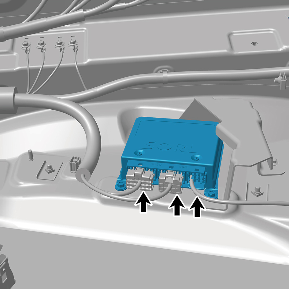
controller assembly.
7
Remove 3 fixing bolts of the air suspension controller
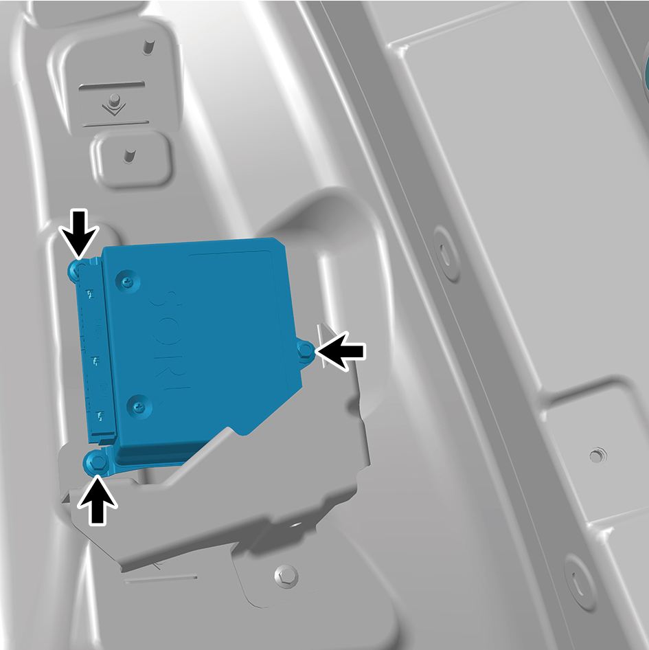
assembly.
8
Remove the air suspension controller assembly.
Installation Procedures
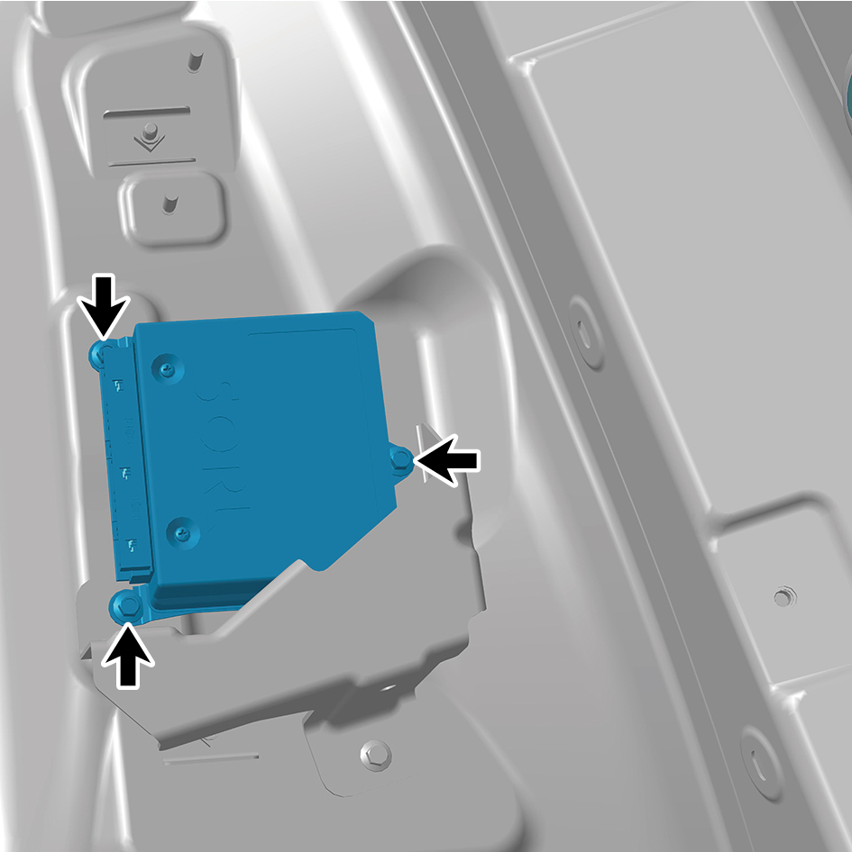
1
Move the air suspension controller assembly to the
mounting position.
2
Install 3 fixing bolts of the air suspension controller
assembly.
Torque: (8 +/- .75) ft lbs
3
Connect 3 harness connectors of the air suspension
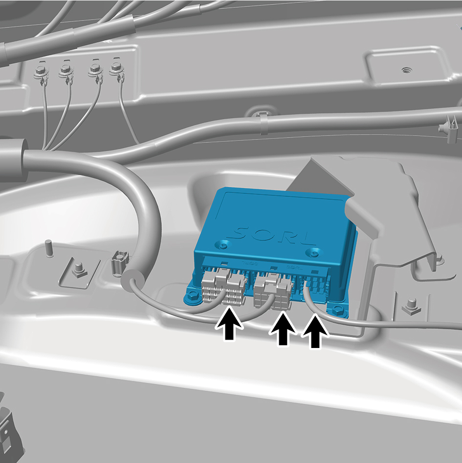
controller assembly.
caution
The harness is firmly connected following the
principal of "insert until a click is heard for
confirmation".
4
Install the right storage box assembly.
5
Install the IP right upper trim panel assembly.
6
Connect the battery negative cable.
7
Close the front flip cover plate.
8
Close the door.
caution
After replacing the air suspension controller
assembly, it is necessary to connect a scan tool for
flashing and recalibrate the height.
8.8.5.2 Replacement of Airbag Solenoid Valve Assembly
Assembly
Removal Procedures
1
Release air pressure from the brake system.
2
Open the door.
3
Open the front flip cover plate.
4
Disconnect the battery negative cable.
caution
power down the high-voltage system before
disconnecting the negative pole of the storage
battery.
5
Disconnect 1 harness connector of the airbag solenoid
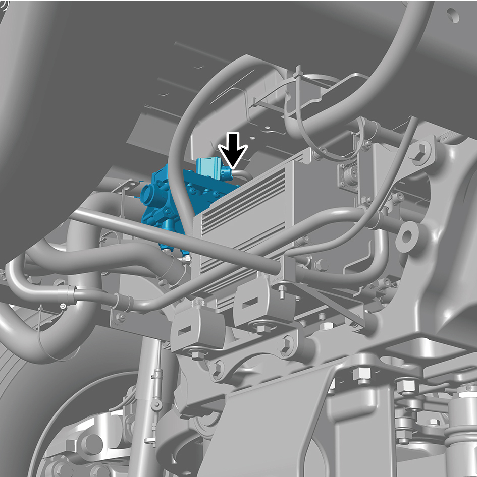
valve assembly.
6
Disconnect 4 air pipes of the airbag solenoid valve
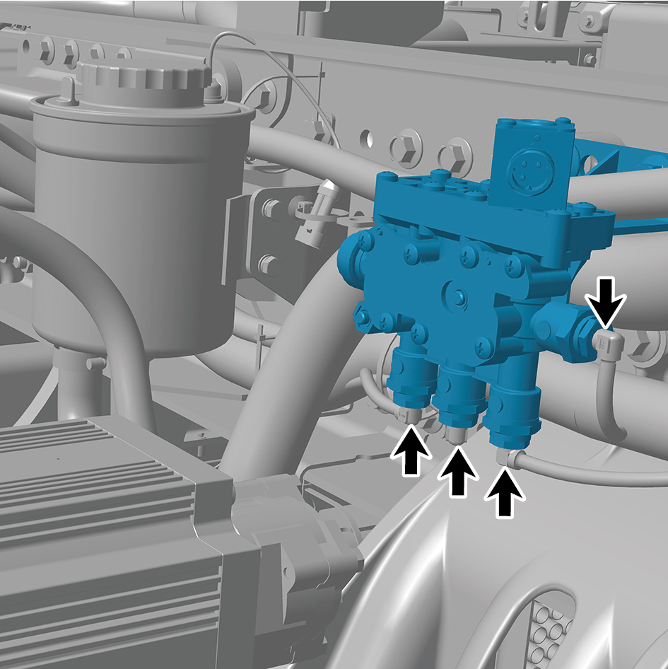
assembly.
7
Remove 2 fixing bolts and nuts of the airbag solenoid
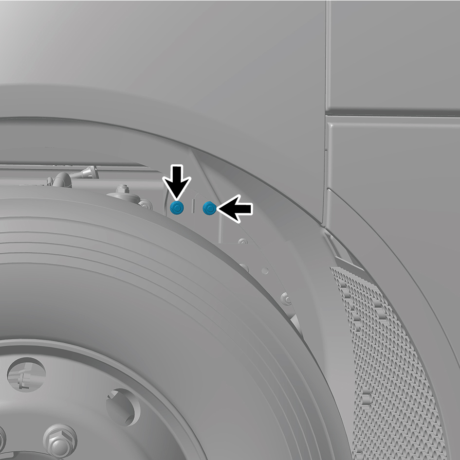
valve assembly.
8
Remove the airbag solenoid valve assembly.
Installation Procedures
1
Move the airbag solenoid valve assembly to the mounting
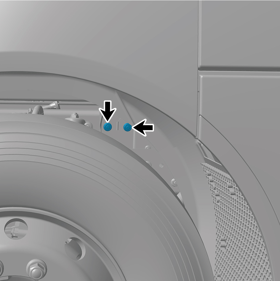
position.
2
Install 2 fixing bolts and nuts of the airbag solenoid valve
assembly.
Torque: (103 +/- 7.5) ft lbs
3
Connect 4 air pipes of the airbag solenoid valve assembly.
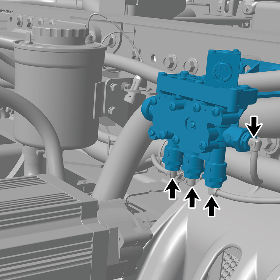
4
Connect 1 harness connector of the airbag solenoid valve
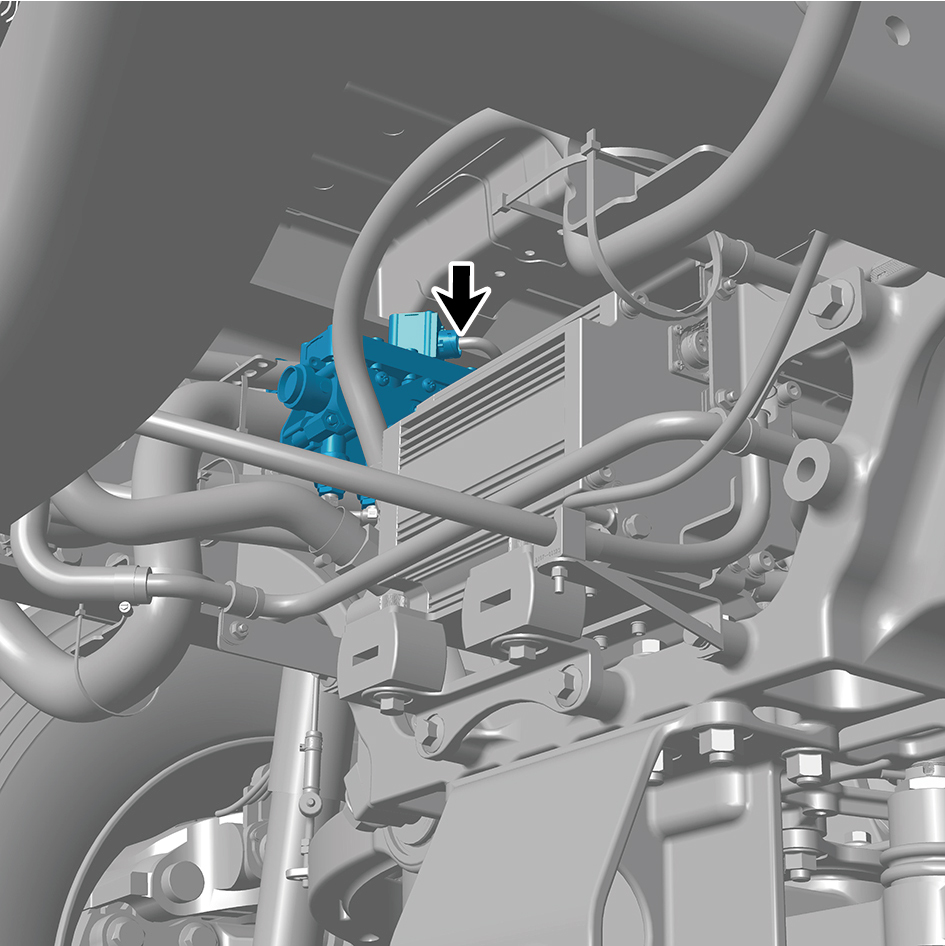
assembly.
caution
The harness is firmly connected following the
principal of "insert until a click is heard for
confirmation".
5
Connect the battery negative cable.
6
Close the front flip cover plate.
7
Close the door.
8.8.5.3 Replacement of Airbag Solenoid Valve Bracket
Bracket
Removal Procedures
1
Release air pressure from the brake system.
2
Open the door.
3
Open the front flip cover plate.
4
Disconnect the battery negative cable.
caution
power down the high-voltage system before
disconnecting the negative pole of the storage
battery.
5
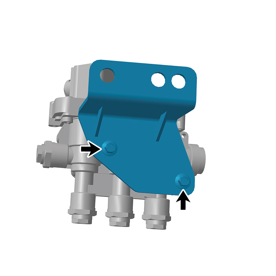
Remove the airbag solenoid valve assembly with bracket.
6
Remove 2 fixing bolts of the airbag solenoid valve bracket.
7
Remove the airbag solenoid valve bracket.
Installation Procedures
1
Move the airbag solenoid valve bracket to the mounting
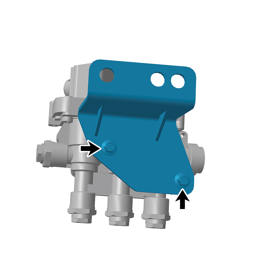
position.
2
Install 2 fixing bolts of the airbag solenoid valve bracket.
Torque:(18.5 +/- 2 (ft lbs)
3
Install the airbag solenoid valve assembly with bracket.
4
Connect the battery negative cable.
5
Close the front flip cover plate.
6
Close the door.
8.8.5.4 Replacement of Overflow Valve Assembly
Assembly
Removal Procedures
1
Open the door.
2
Open the front flip cover plate.
3
Disconnect the battery negative cable.
caution
power down the high-voltage system before
disconnecting the negative pole of the storage
battery.
4
Remove the back integrated bracket side cover plate
assembly (left).
5
Remove the back integrated bracket side cover plate
assembly (right).
6
Remove the back integrated bracket middle cover plate
assembly.
7
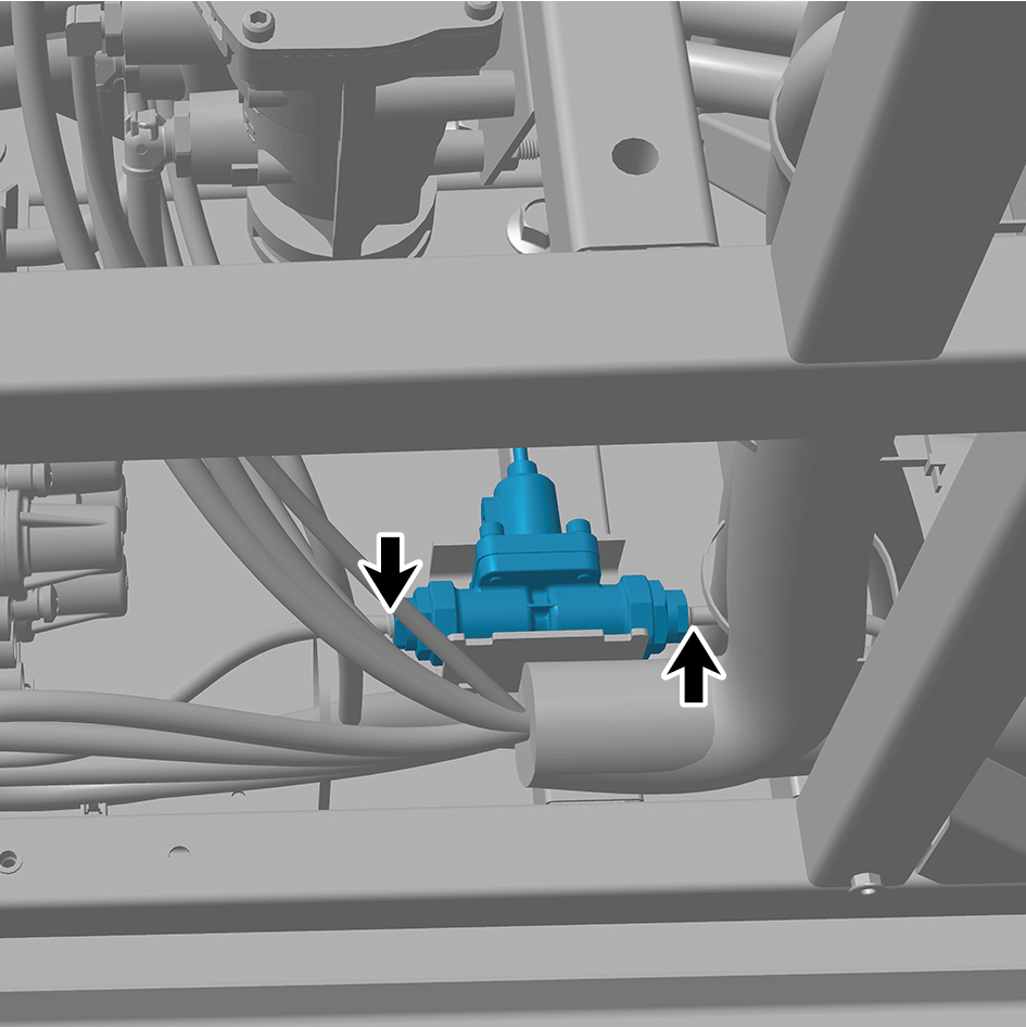
Disconnect 2 air pipes of the overflow valve assembly.
8
Remove 2 straps of the overflow valve assembly.
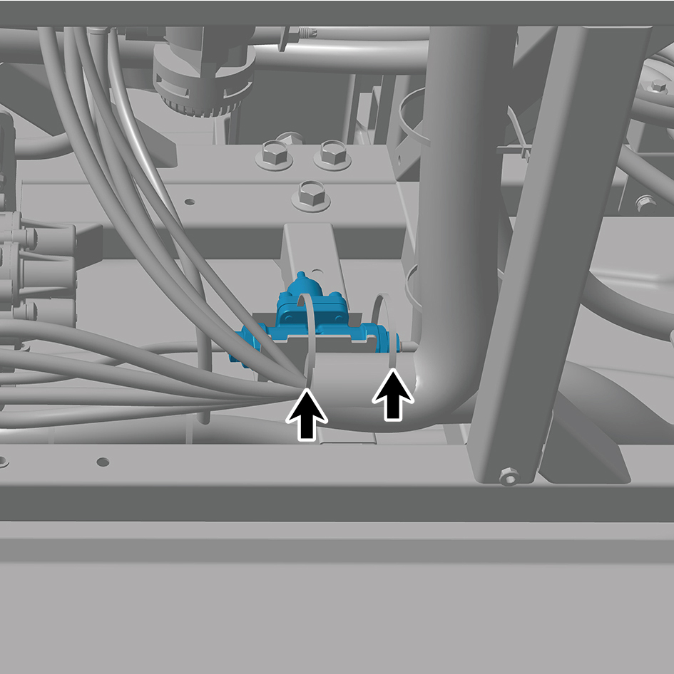
9
Remove the overflow valve assembly.
Installation Procedures
1
Move the overflow valve assembly to the mounting
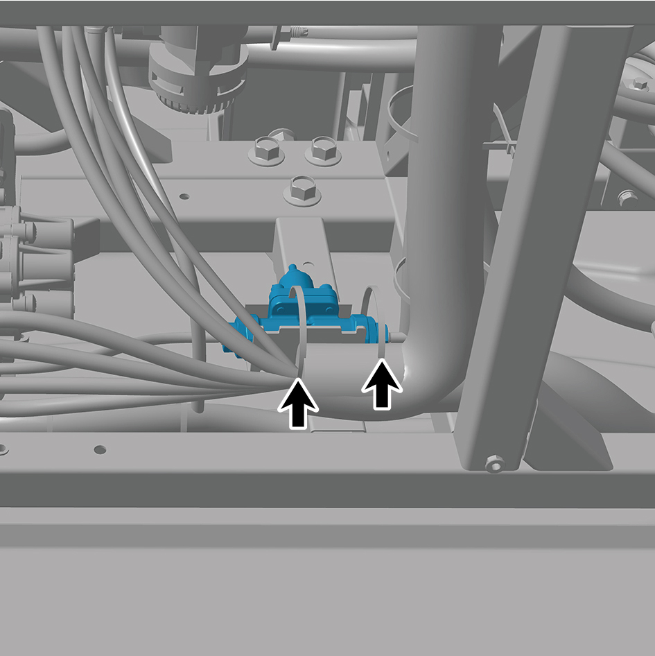
position.
2
Install 2 straps of the overflow valve assembly.
3
Connect 2 air pipes of the overflow valve assembly.
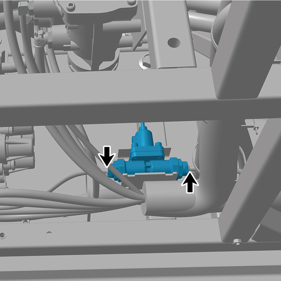
4
Install the back integrated bracket middle cover plate
assembly.
5
Install the back integrated bracket side cover plate
assembly (right).
6
Install the back integrated bracket side cover plate
assembly (left).
7
Connect the battery negative cable.
8
Close the front flip cover plate.
9
Close the door.
8.8.5.5 Replacement of Pressure Sensor Assembly
Assembly
Removal Procedures
1
Open the door.
2
Open the front flip cover plate.
3
Disconnect the battery negative cable.
caution
power down the high-voltage system before
disconnecting the negative pole of the storage
battery.
4
Disconnect 1 harness connector of the pressure sensor
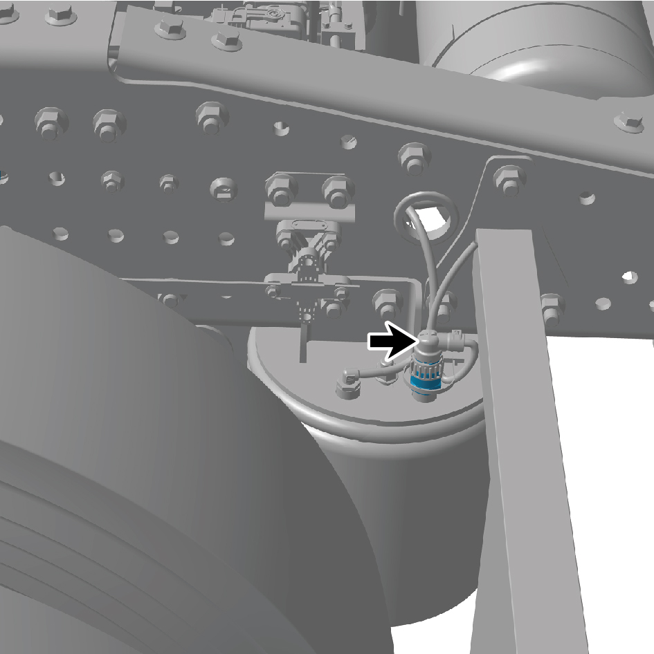
assembly.
5
Remove the pressure sensor assembly.
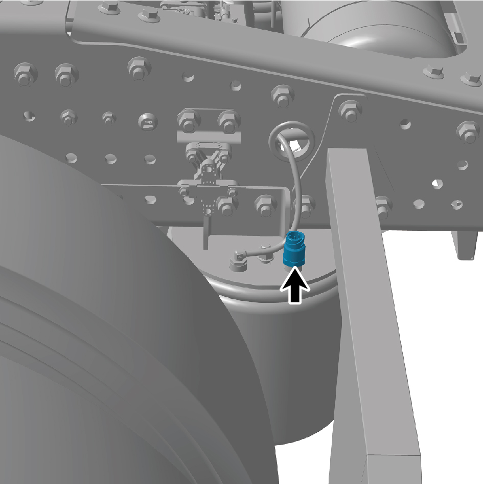
Installation Procedures
1
Move the pressure sensor assembly to the mounting
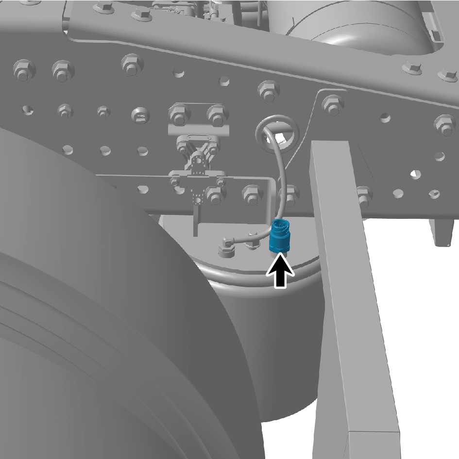
position.
2
Connect 1 harness connector of the pressure sensor
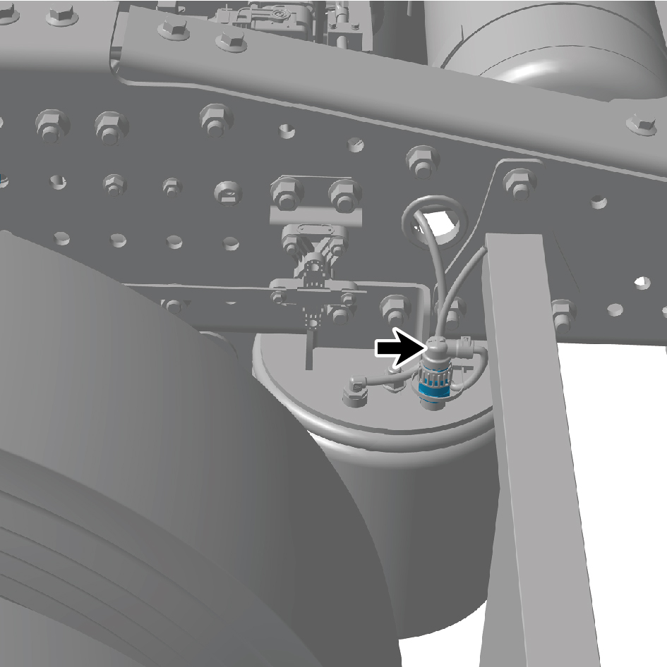
assembly.
caution
The harness is firmly connected following the
principal of "insert until a click is heard for
confirmation".
3
Connect the battery negative cable.
4
Close the front flip cover plate.
5
Close the door.
8.8.5.6 Replacement of Height Sensor Assembly
Assembly
Removal Procedures
1
Open the door.
2
Open the front flip cover plate.
3
Disconnect the battery negative cable.
caution
power down the high-voltage system before
disconnecting the negative pole of the storage
battery.
4
Disconnect 1 harness connector of the height sensor
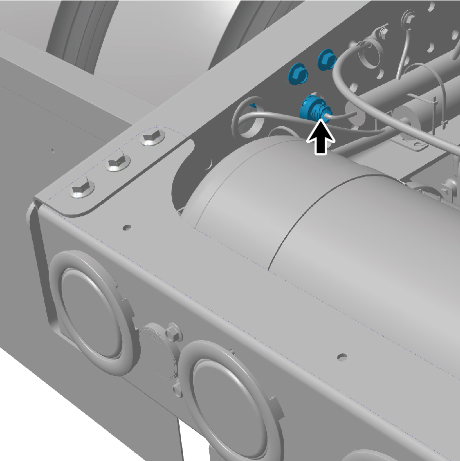
assembly.
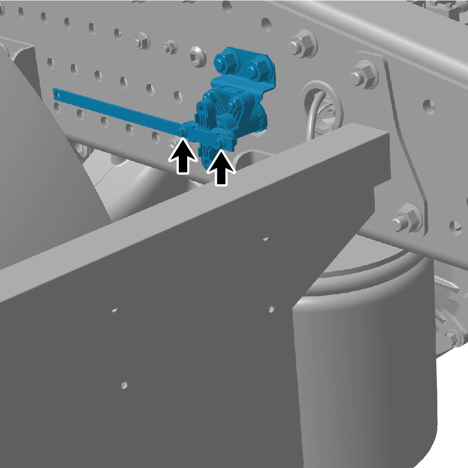
5
Remove 2 fixing bolts of the height sensor assembly.
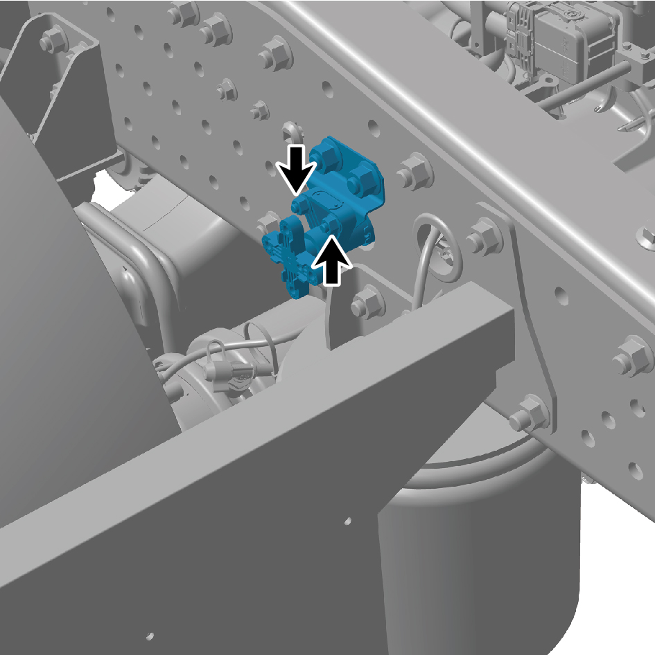
6
Remove 2 fixing nuts of the height sensor assembly.
7
Remove the height sensor assembly.
Installation Procedures
1
Move the height sensor assembly to the mounting
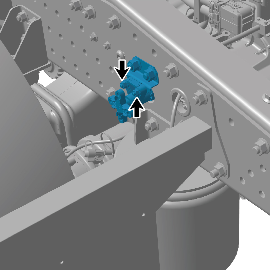
position.
2
Install 2 fixing nuts of the height sensor assembly.
Torque: (18.5 +/- 2) ft lbs
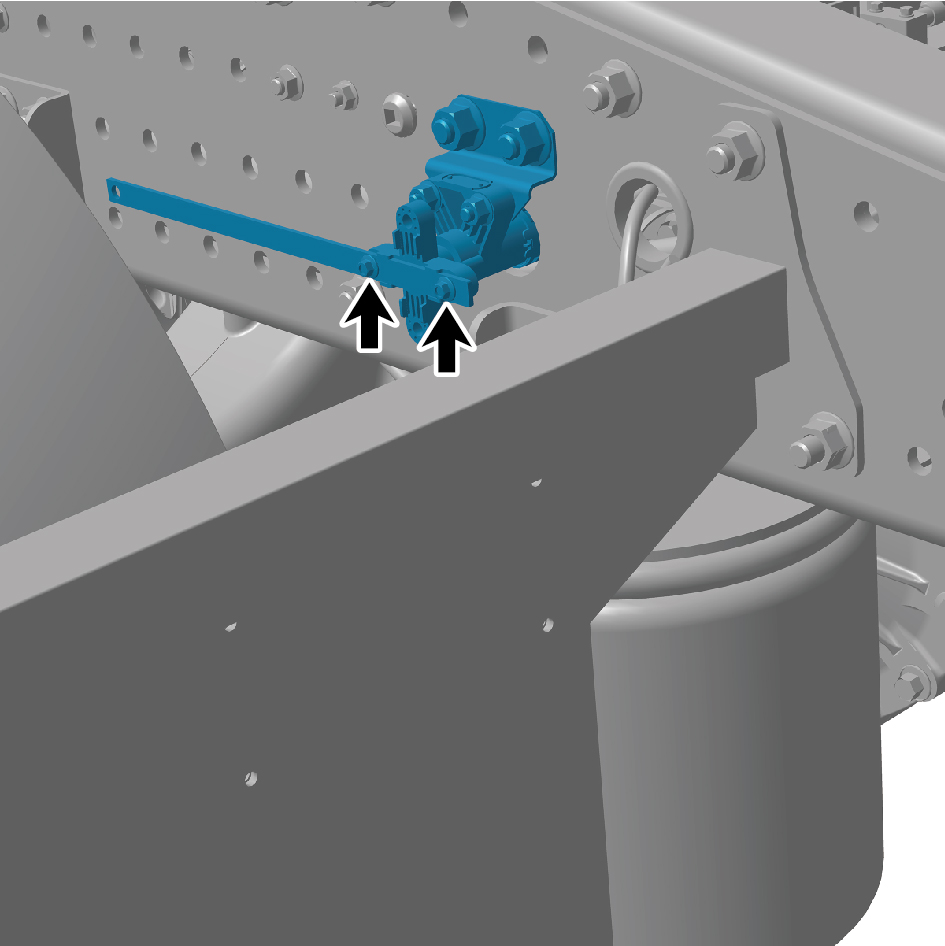
3
Install 2 fixing bolts of the height sensor assembly.
Torque: (18.5 +/- 2) ft lbs
4
Connect 1 harness connector of the height sensor
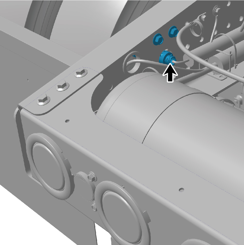
assembly.
caution
The harness is firmly connected following the
principal of "insert until a click is heard for
confirmation".
5
Connect the battery negative cable.
6
Close the front flip cover plate.
7
Close the door.