← Back to Contents
8 Chassis / 8.7 Rear Suspension Device | PDF pages 1927-1955
8.7 Rear Suspension Device
8.7 Rear Suspension Device
8.7.1 Specifications
8.7.1.1 Fastener Specifications
Range Of Torque
Fastener Specifications
Specifications
Foot Pounds of Torque (ft lbs)
The fixing nut connecting the rear air
spring assembly to the upper bracket of
40.5 +/- 3.5 (ft lbs)
M12
the air spring
The fixing nut connecting the rear air
199 +/- 18.5 (ft lbs)
M18
spring assembly and the balance beam
The fixing bolt connecting the bracket
155 +/- 14.75 (ft lbs)
M14
on the air spring to the frame assembly
Fixed nut for balancing beam and E-
516 +/- 37 (ft lbs)
M22
Axle Device rear axle connection
Fixed bolts connecting the pipe beam
228.5 +/- 84.5 (ft lbs)
M16
and thrust rod bracket
The fixing nut connecting the pipe beam
228.5 +/- 84.5 (ft lbs)
M16
and the thrust rod bracket
The fixing nut connecting the thrust rod
228.5 +/- 84.5 (ft lbs)
M16
bracket to the frame assembly
The fixing bolt connecting the X-shaped
516 +/- 37 (ft lbs) (Apply sealant)
M22
control arm assembly to the pipe beam
The fixing nut for the X-shaped control
516 +/- 37 (ft lbs) (Apply sealant)
arm assembly and the E-Axle Device
M22
rear axle connection
The fixed nut connecting the X-shaped
516 +/- 37 (ft lbs) (Apply sealant)
control arm assembly and the E-Axle
M22
Device middle axle
The fixing bolt connecting the shock
516 +/- 37 (ft lbs) (Apply sealant)
M20
absorber assembly (rear) and the
balance beam
The fixing bolt connecting the shock
516 +/- 37 (ft lbs) (Apply sealant)
M20
absorber assembly (rear) to the shock
absorber bracket
The fixing nut connecting the shock
516 +/- 37 (ft lbs) (Apply sealant)
M20
absorber assembly (rear) to the shock
absorber bracket
The fixing bolts connecting the shock
155 +/- 14.75 (ft lbs)
M14
absorber bracket to the frame assembly
The fixing nut connecting the shock
155 +/- 14.75 (ft lbs)
M14
absorber bracket to the frame assembly
Range Of Torque
Fastener Specifications
Specifications
Foot Pounds of Torque (ft lbs)
The fixing bolt connecting the limit buffer
155 +/- 14.75 (ft lbs)
M14
block assembly and the frame assembly
The fixing bolt connecting the limit buffer
155 +/- 14.75 (ft lbs)
M14
block assembly and the frame assembly
The fixing bolts connecting the
516 +/- 37 (ft lbs) (Apply sealant)
M20
longitudinal thrust rod assembly and the
thrust rod bracket
The fixing nut connecting the
516 +/- 37 (ft lbs) (Apply sealant)
M20
longitudinal thrust rod assembly and the
thrust rod bracket
The fixing bolts connecting the
516 +/- 37 (ft lbs) (Apply sealant)
M20
longitudinal thrust rod assembly and the
balance beam
The fixing bolts connecting the
516 +/- 37 (ft lbs) (Apply sealant)
M20
longitudinal thrust rod assembly and the
balance beam
8.7.2 Decomposition Diagram
8.7.2.1 Decomposition Diagram
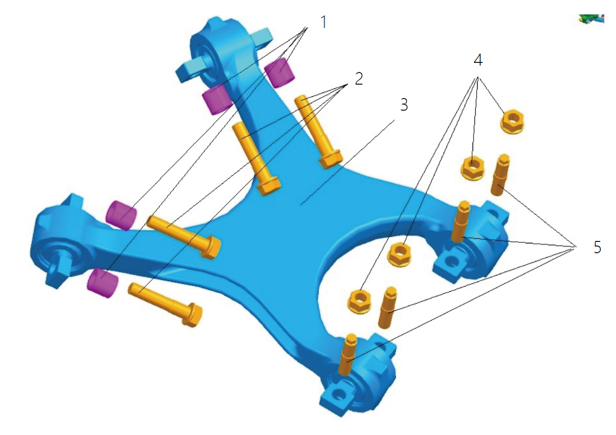
1.
Bush
4.
Nut M22x1.5(Spiralock)
5.
2.
Hexagon Flange Bolt M22x1.5
Double Stud M22x2.5x1.5
3.
X-Link Bracket Assy
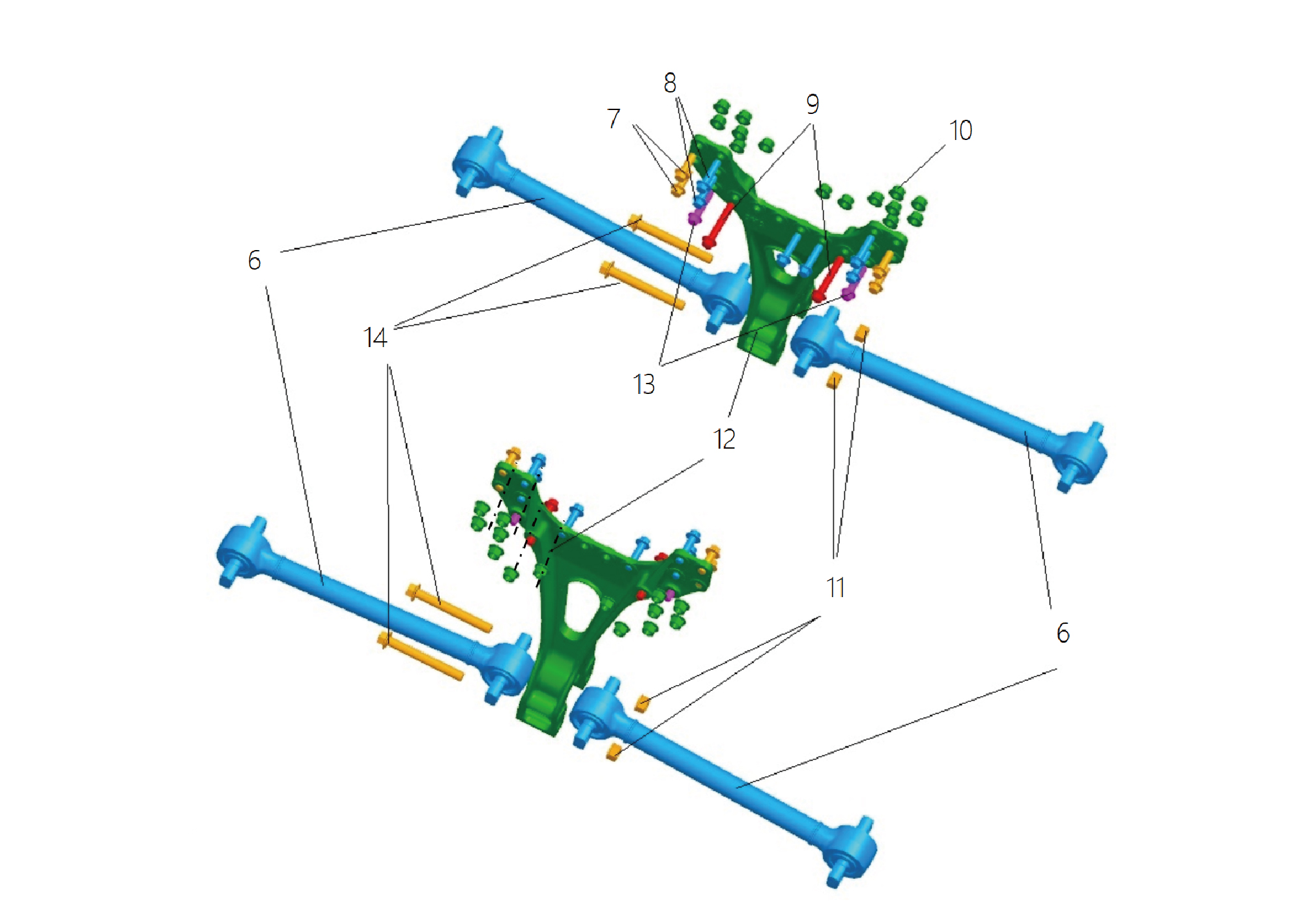
6.
Trailing Arm Assy
11.
Nut M20x1.5(Spiralock)
7.
Hexagon Flange Bolt
12.
Trailing Arm Bravket
8.
Hexagon Flange Bolt
13.
Hexagon Flange Bolt
9.
Hexagon Flange Bolt
14.
Hexagon Flange Bolt
10.
Hexagon Flange Lock Nut_All Metal
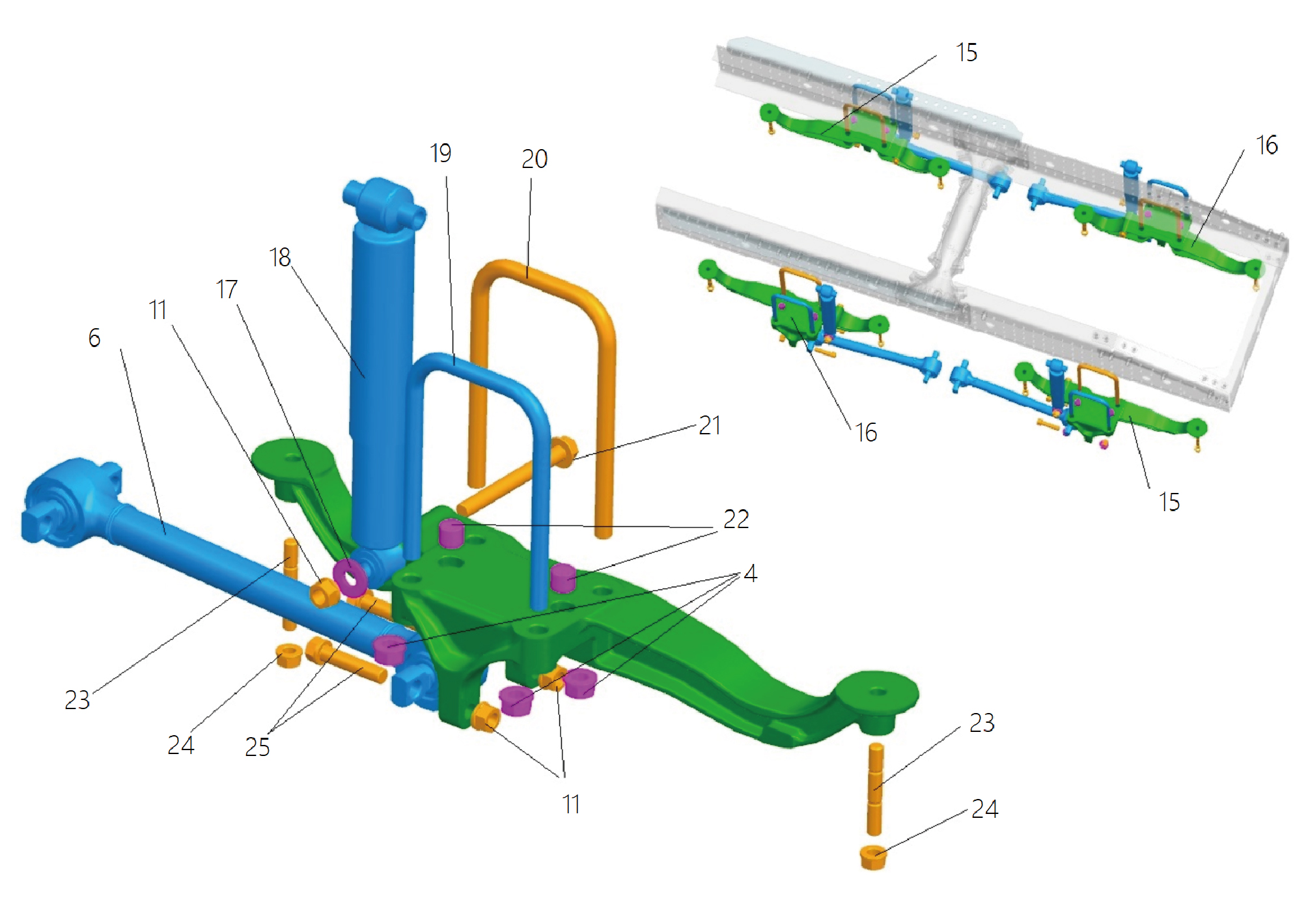
4.
19.
U-Bolt1
Nut M22x1.5(Spiralock)
6.
Trailing Arm Assy
20.
U-Bolt2
11.
21.
Hexagon Flange Bolt
Nut M20x1.5(Spiralock)
15.
22.
Equalizer Pin
Axle Pressure Equalizer-Left
16.
23.
Axle Pressure Equalizer-Right
Double Stud M18x2x1.5
17.
24.
Shock Absorber Lower Gasket
Nut M18x1.5(Spiralock)
18.
25.
Hexagon Flange Bolt
Rear Shock Absorber Assy
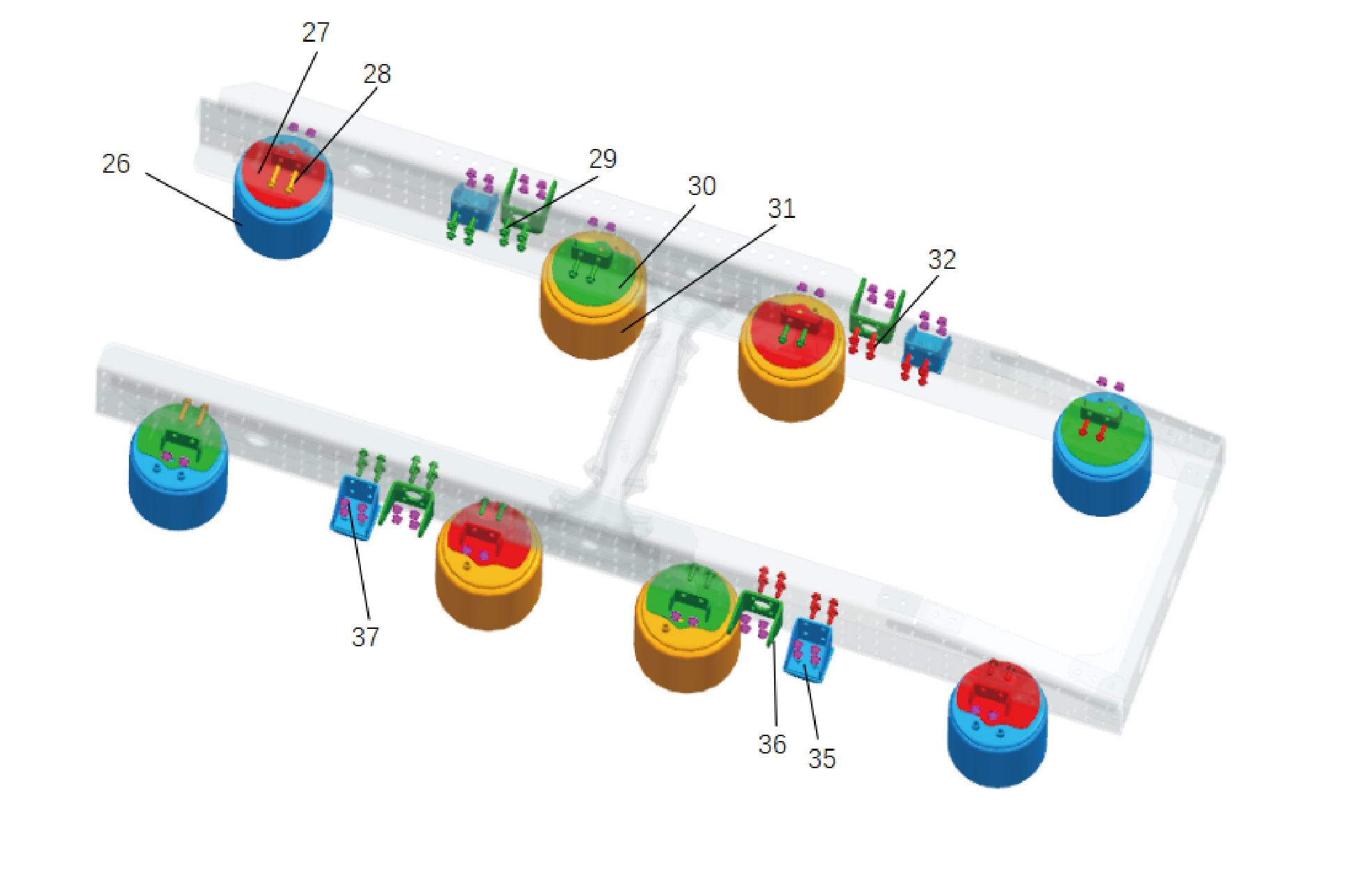
26.
31.
Air Spring-260
Air Spring-280
27.
32.
Hexagon Flange Bolt
Air Spring Mounting Bracket 4
28.
Hexagon Flange Bolt
35.
Buffering Stopper Assy
29.
Hexagon Flange Bolt
36.
Shock Absorber Bracket
30.
37.
Hexagon Flange Lock Nut_All Metal
Air Spring Mounting Bracket 3
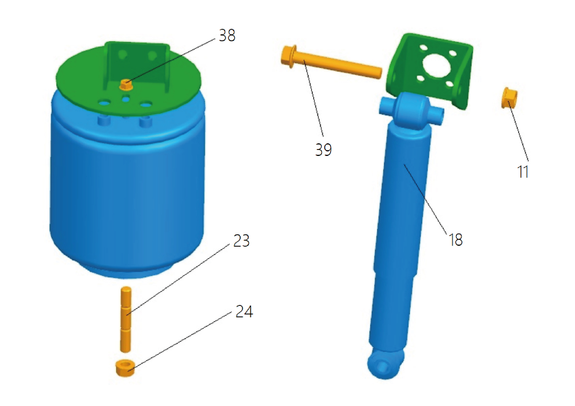
11.
24.
Nut M20x1.5(Spiralock)
Nut M18x1.5(Spiralock)
18.
38.
Rear Shock Absorber Assy
Nut M12x1.5(Spiralock)
23.
39.
Hexagon Flange Bolt
Double Stud M18x2x1.5
8.7.3 Dismantling and Installation
8.7.3.1 Replacement of Rear Air Spring Assembly - 260
Assembly - 260
Removal Procedures
1
Turn off the vehicle power and place the parking wedge to
prevent the vehicle from rolling.
2
Jack the rear end of the vehicle.
3
Remove the drive wheel (right front)
4
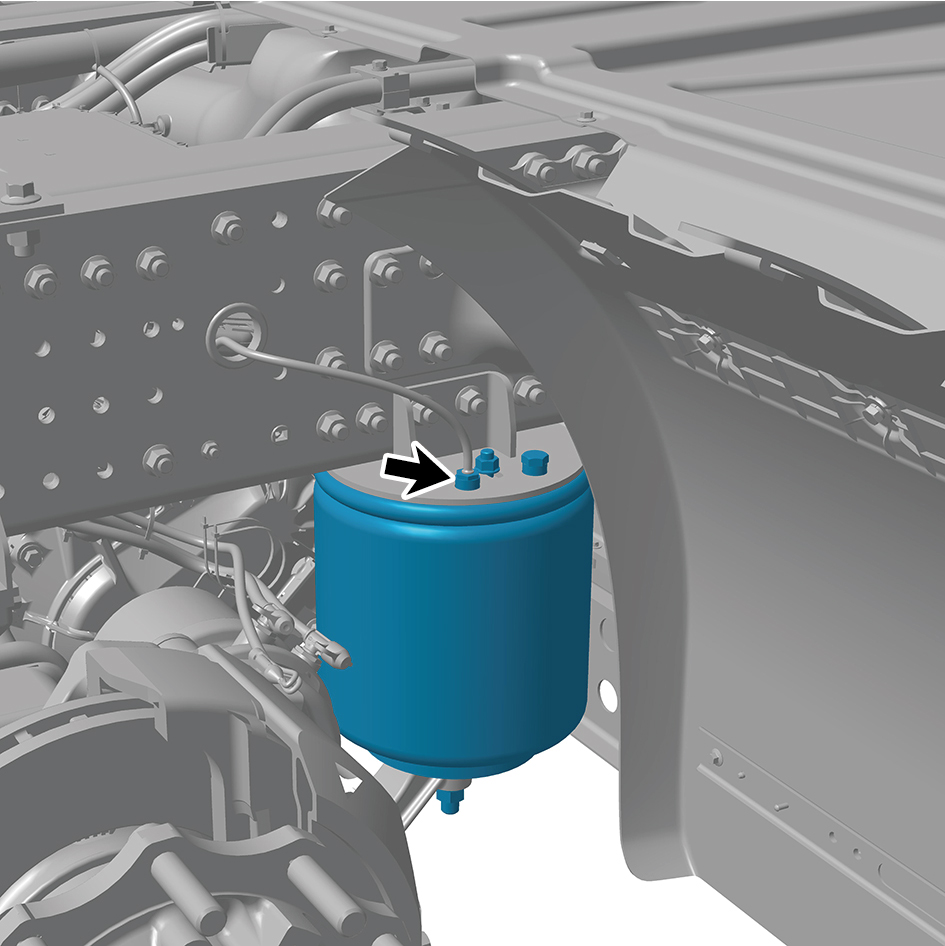
Disconnect 1 pipeline of the rear air spring assembly -
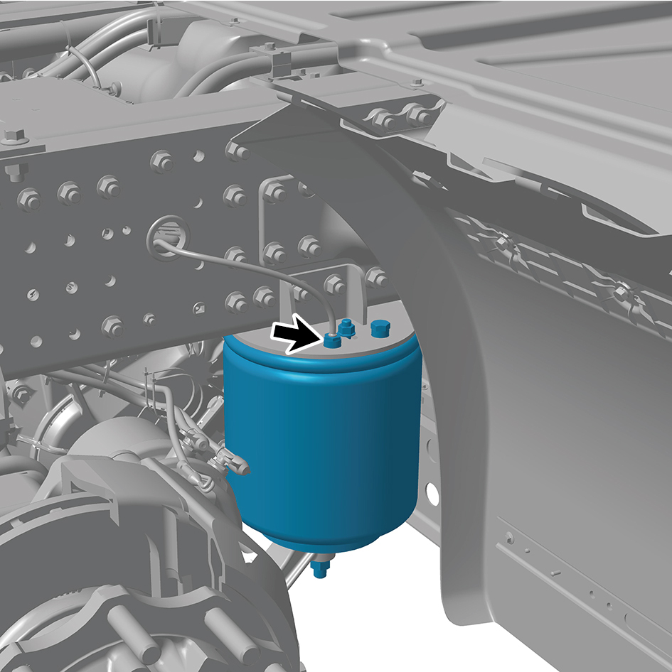
260.
5
Remove 1 plug of the rear air spring assembly - 260.
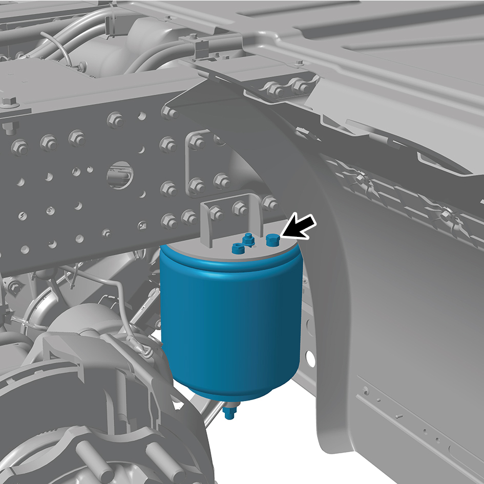
6
Remove 1 fixing nut of the rear air spring assembly - 260.
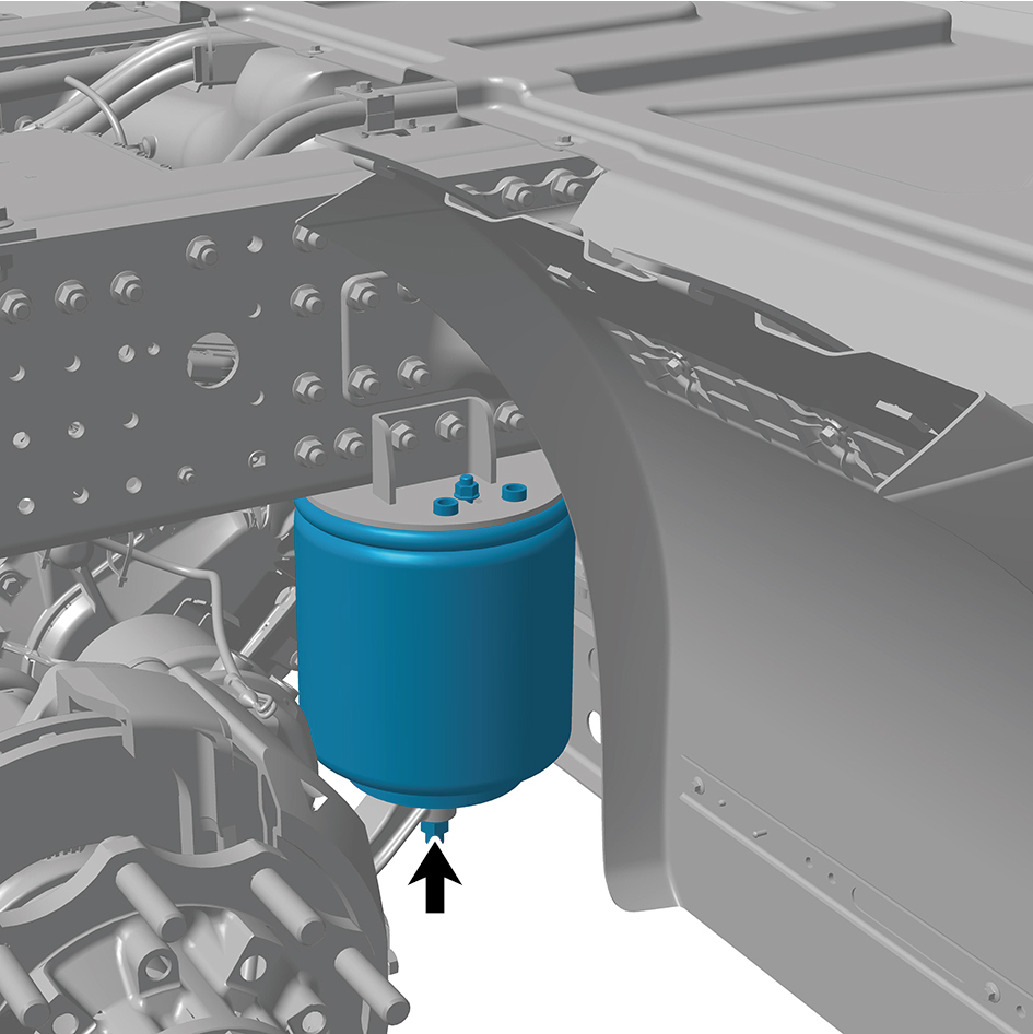
7
Remove 1 fixing nut of the rear air spring assembly - 260.
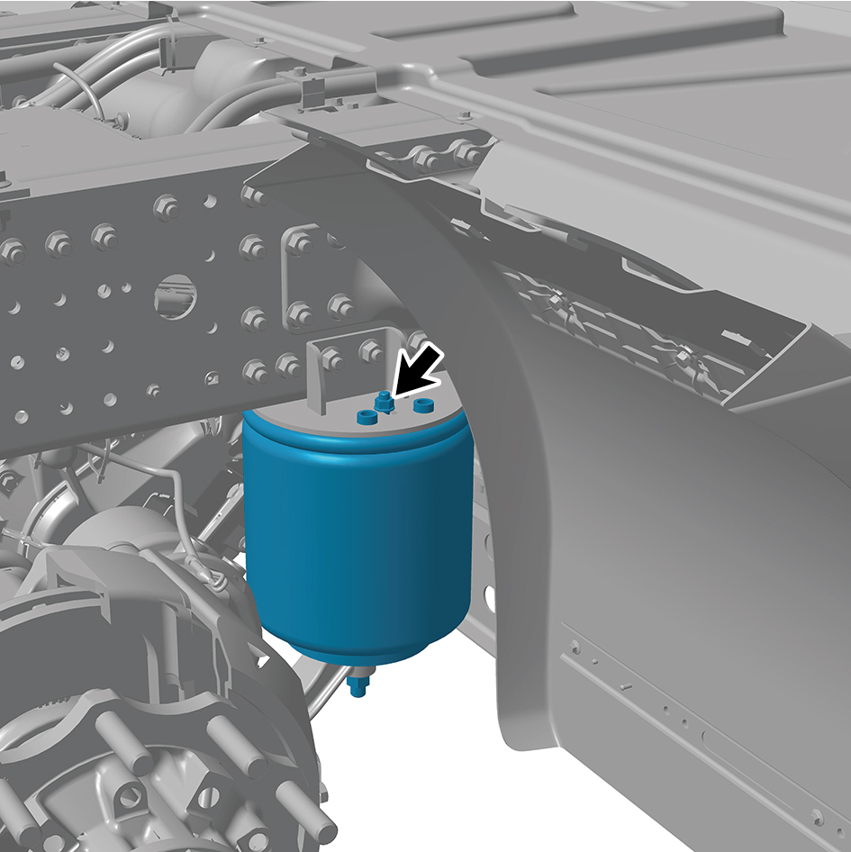
8
Remove the rear air spring assembly - 260.
Installation Procedures
1
Move the rear air spring assembly - 260 to the mounting
position.
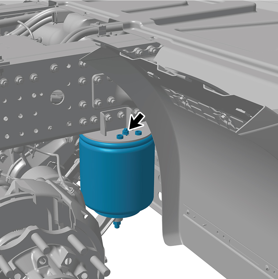
2
Install 1 fixing nut of the rear air spring assembly - 260.
Torque: 40.5 +/- 3.5 (ft lbs)
3
Install 1 fixing nut of the rear air spring assembly - 260.
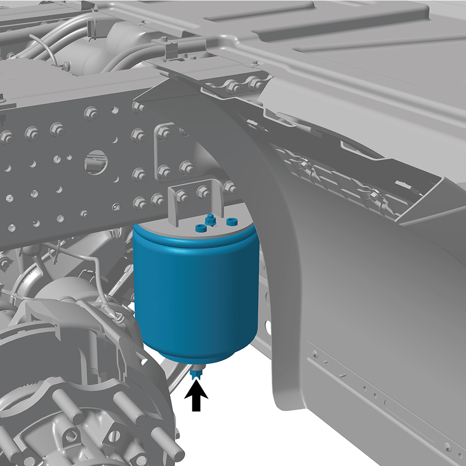
Torque: 199 +/- 18.5 (ft lbs)
4
Install 1 plug of the rear air spring assembly - 260.
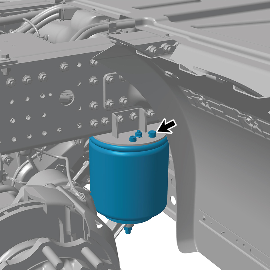
Torque:7.5 - 12 (ft lbs)
5
Connect 1 pipeline of the rear air spring assembly - 260.
6
Install the drive wheel (right front).
7
Lower the rear end of the vehicle.
8.7.3.2 Replacement of Rear Air Spring Assembly - 280
Assembly - 280
Removal Procedures
1
Turn off the vehicle power and place the parking wedge to
prevent the vehicle from rolling.
2
Jack the rear end of the vehicle.
3
Remove the drive wheel (right front)
4
Disconnect 1 pipeline of the rear air spring assembly -
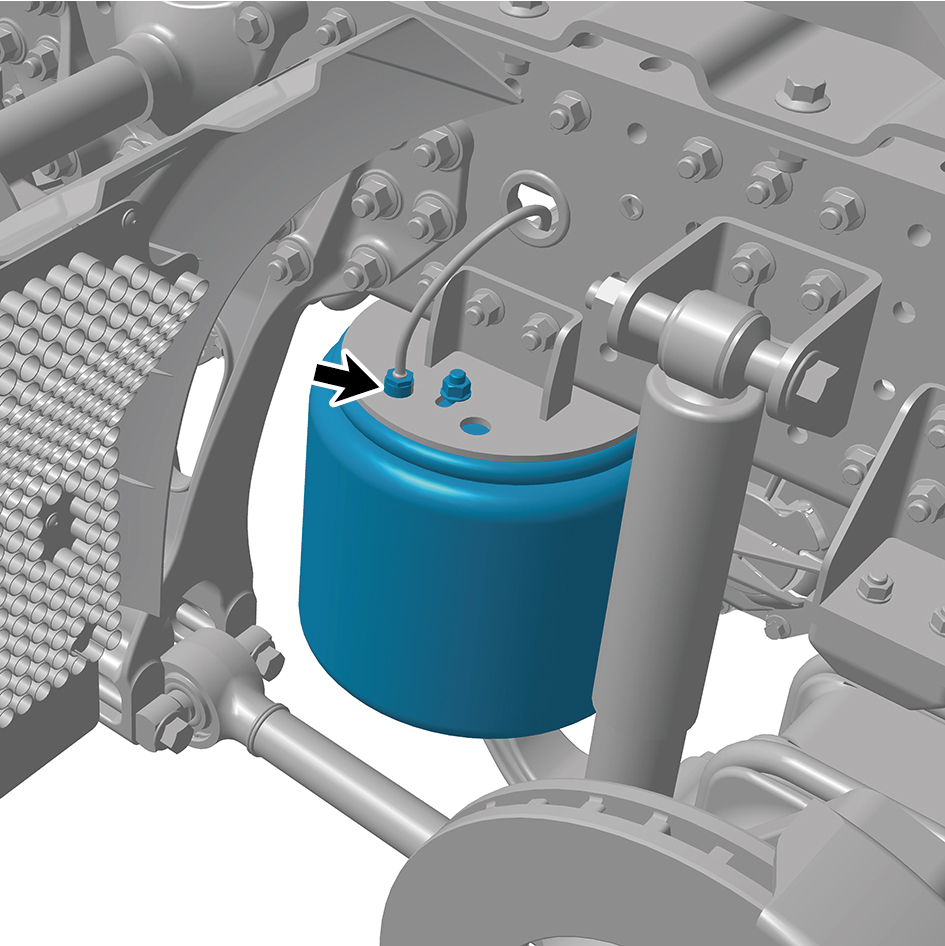
280.
5
Remove 1 fixing nut of the rear air spring assembly - 280.
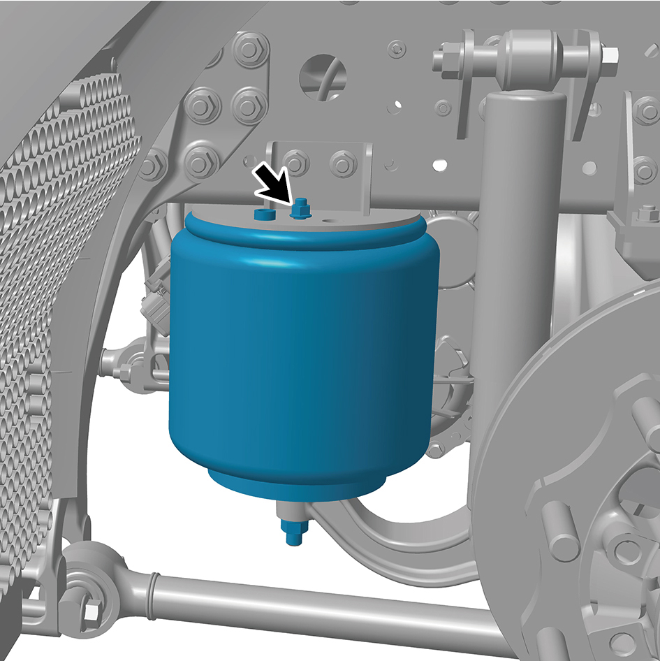
6
Remove 1 fixing nut of the rear air spring assembly - 280.
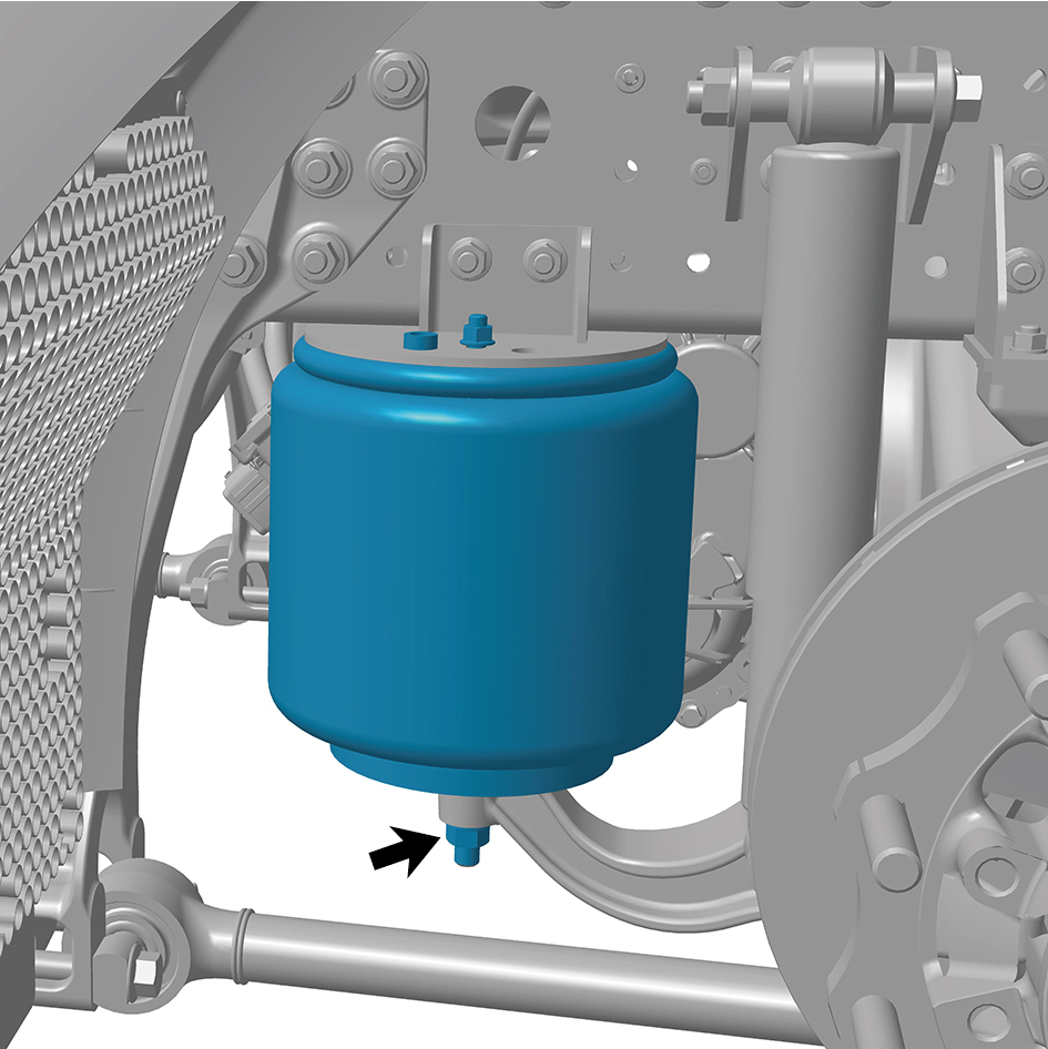
7
Remove the rear air spring assembly - 280.
Installation Procedures
1
Move the rear air spring assembly - 280 to the mounting
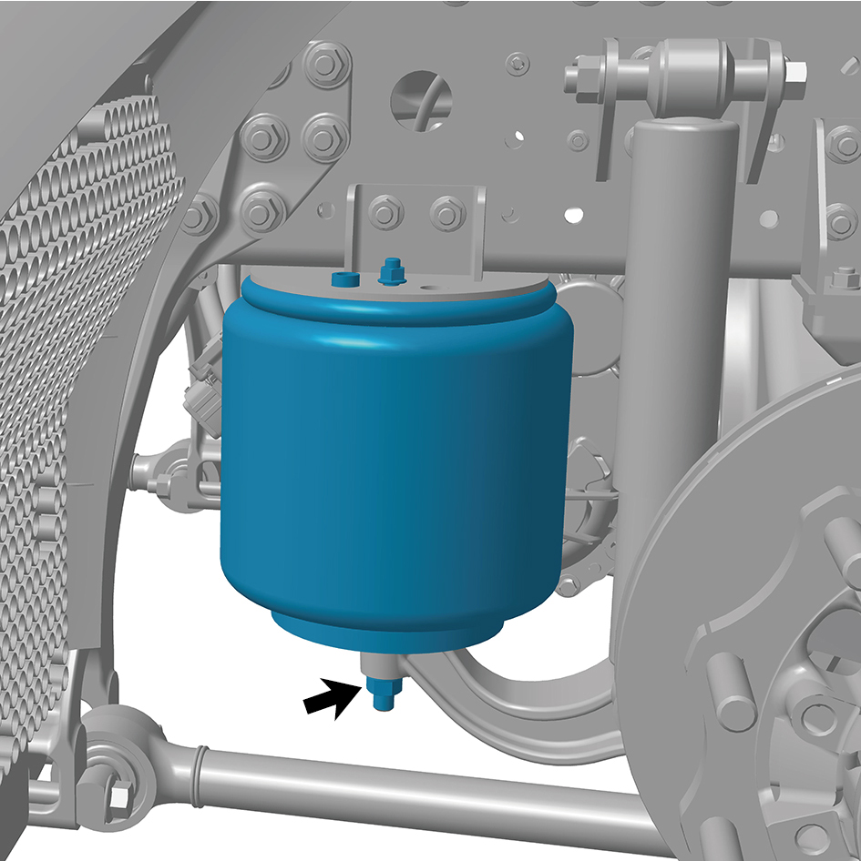
position.
2
Install 1 fixing nut of the rear air spring assembly - 280.
Torque: 199 +/- 18.5 (ft lbs)
3
Install 1 fixing nut of the rear air spring assembly - 280.
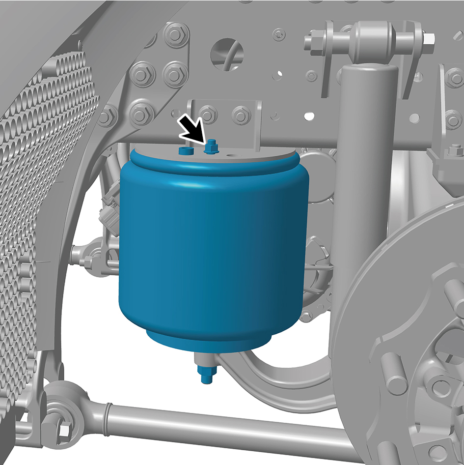
Torque:40.5 +/- 3.5 (ft lbs)
4
Connect 1 pipeline of the rear air spring assembly - 280.
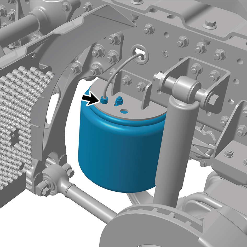
5
Install the drive wheel (right front).
6
Lower the rear end of the vehicle.
8.7.3.3 Replacement of Balance Beam (left)
Removal Procedures
1
Turn off the vehicle power and place the parking wedge to
prevent the vehicle from rolling.
2
Jack the rear end of the vehicle.
3
Loosen the air spring air pipe joint and exhaust the air
inside.
4
Remove the drive wheel (rear left).
5
Remove the shock absorber assembly (rear).
6
Remove the longitudinal thrust rod assembly.
7
Remove the rear spring U-bolt.
8
Remove 1 fixing bolt and nut of the balance beam (left).
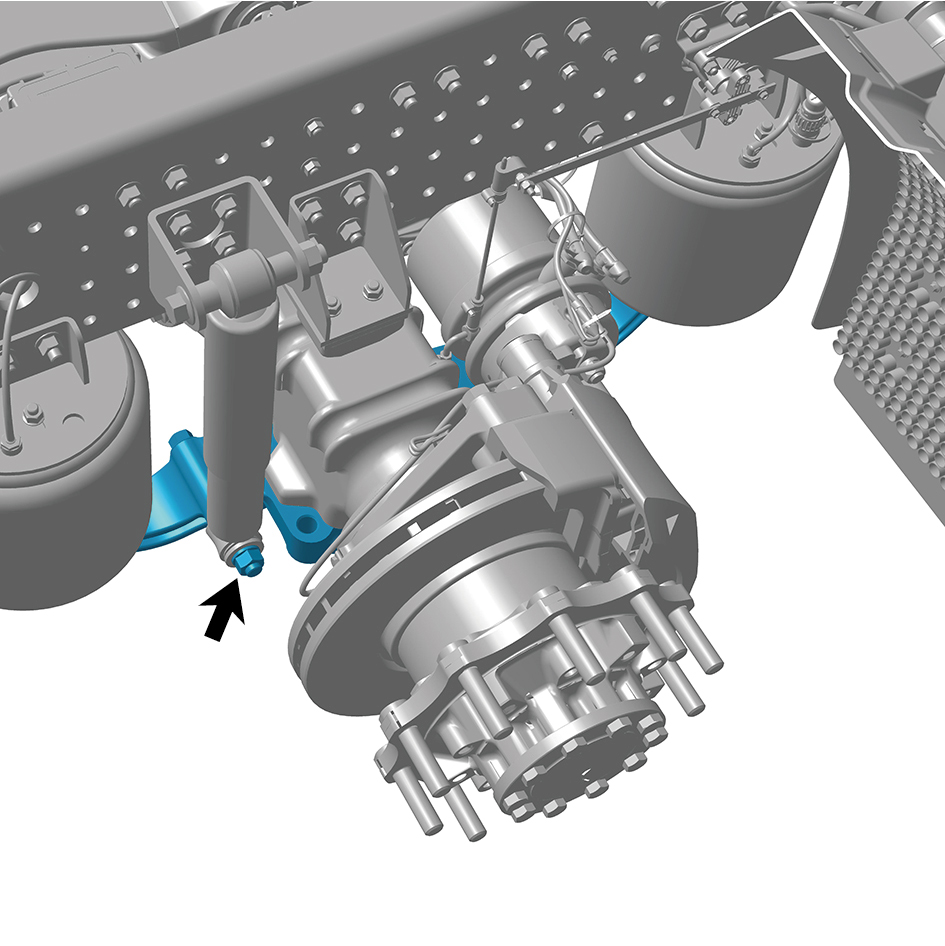
9
Remove 2 fixing nuts of the balance beam (left).
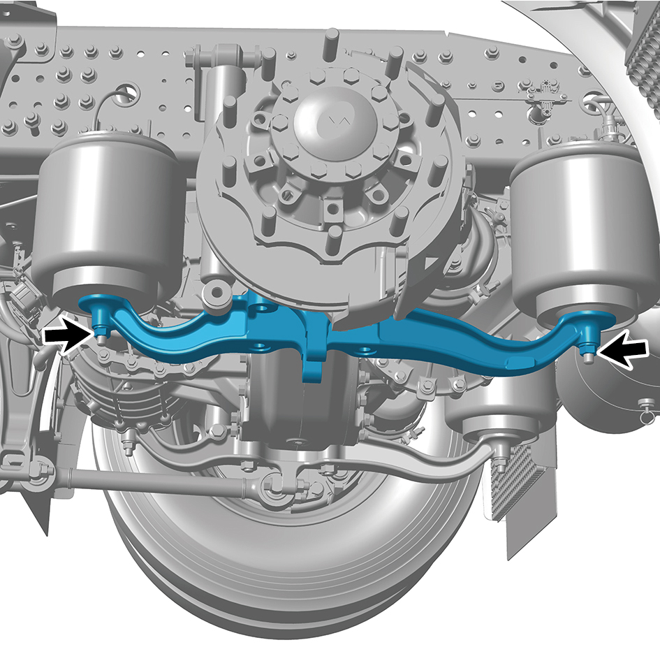
10
Remove the balance beam (left).
Installation Procedures
1
Move the balance beam (left) to the mounting position.
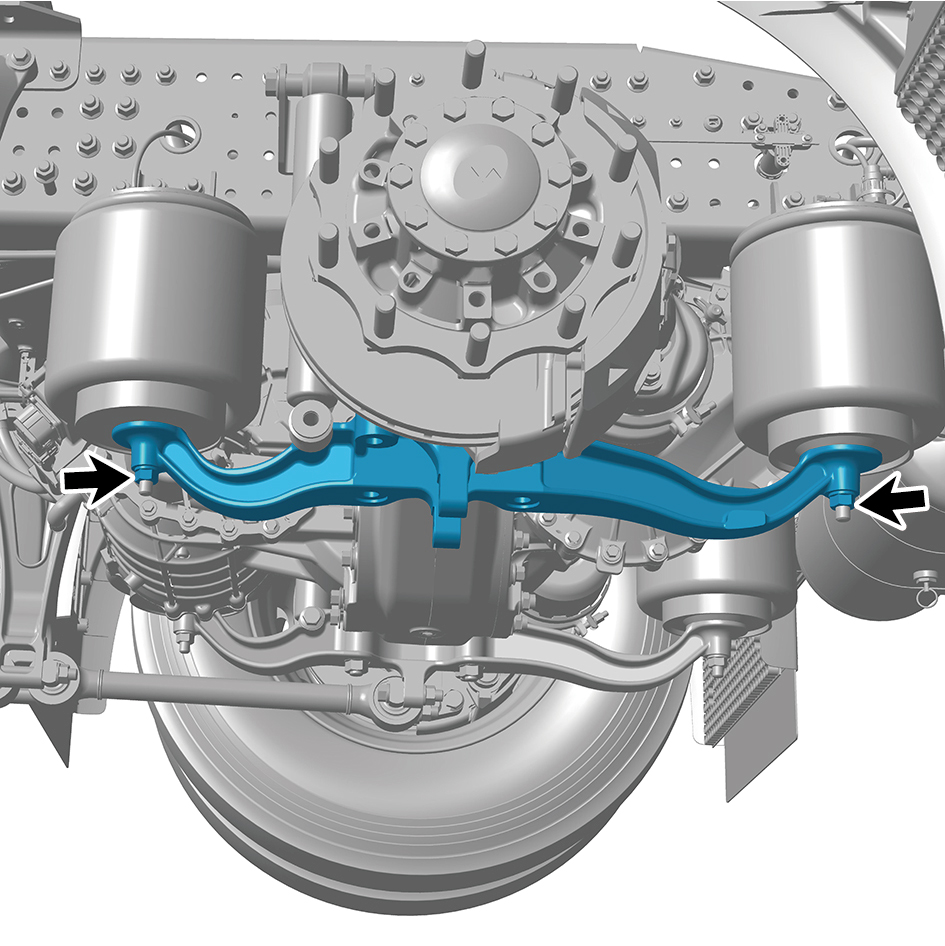
2
Install 2 fixing nuts of the balance beam (left).
Torque: 199 +/- 18.5 (ft lbs)
3
Install 1 fixing bolt and nut of the balance beam (left).
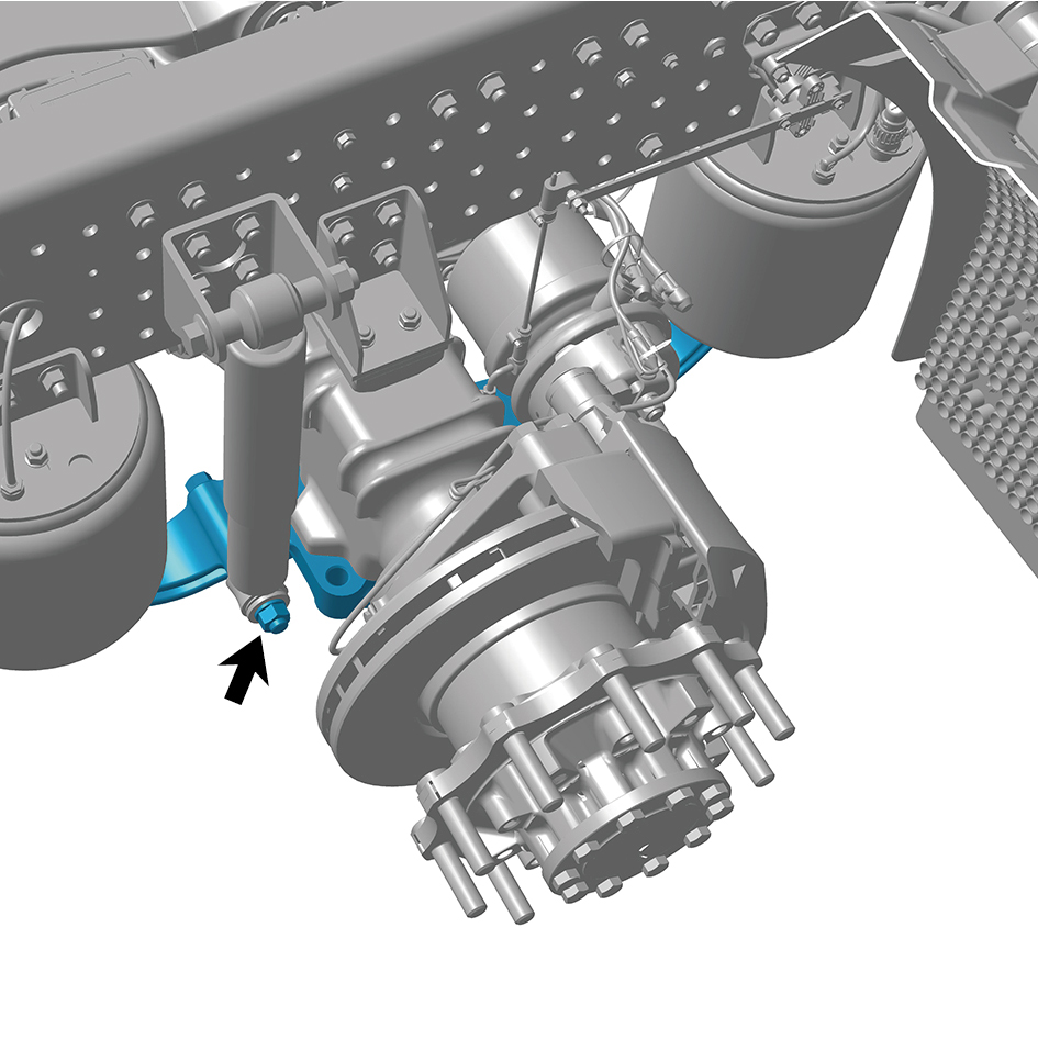
Torque: 405.5 +/- 37 (ft lbs)
4
Install the rear spring U-bolt.
5
Install the longitudinal thrust rod assembly.
6
Install the shock absorber assembly (rear).
7
Install the drive wheel (rear left).
8
Lower the rear end of the vehicle.
8.7.3.4 Replacement of Balance Beam (right)
Removal Procedures
1
Turn off the vehicle power and place the parking wedge to
prevent the vehicle from rolling.
2
Jack the rear end of the vehicle.
3
Loosen the air spring air pipe joint and exhaust the air
inside.
4
Remove the drive wheel (rear right).
5
Remove the shock absorber assembly (rear).
6
Remove the longitudinal thrust rod assembly.
7
Remove the rear spring U-bolt.
8
Remove 1 fixing bolt and nut of the balance beam (right).
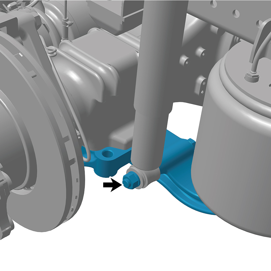
9
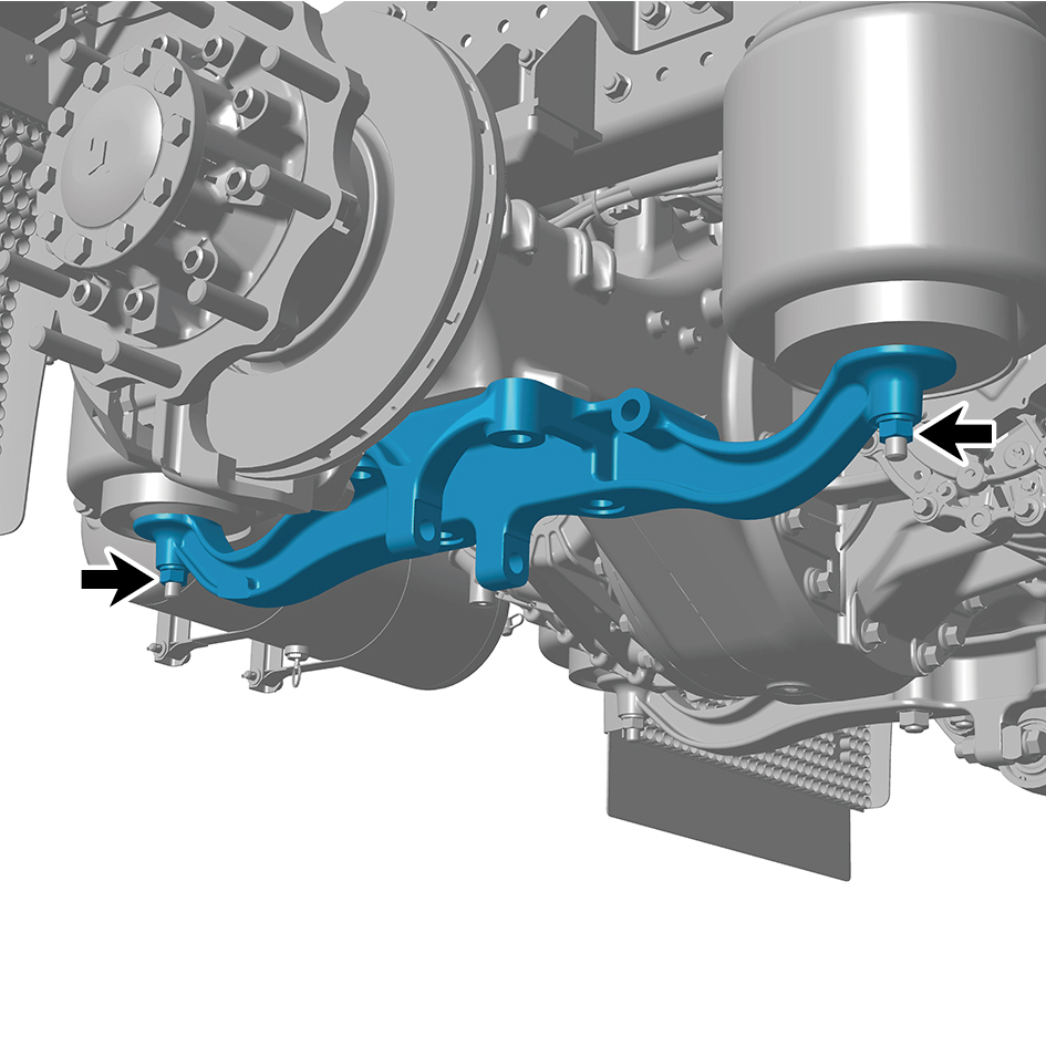
Remove 2 fixing nuts of the balance beam (right).
10
Remove the balance beam (right).
Installation Procedures
1
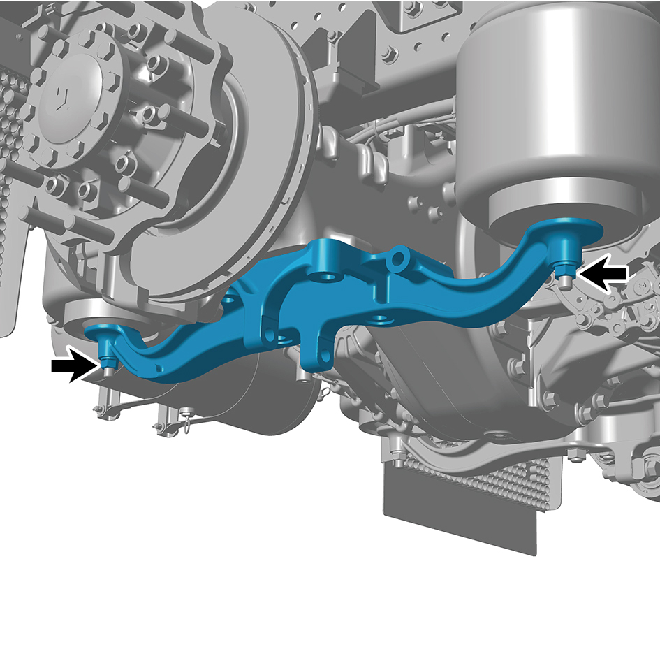
Move the balance beam (right) to the mounting position.
2
Install 2 fixing nuts of the balance beam (right).
Torque:199 +/- 18.5 (ft lbs)
3
Install 1 fixing bolt and nut of the balance beam (right).
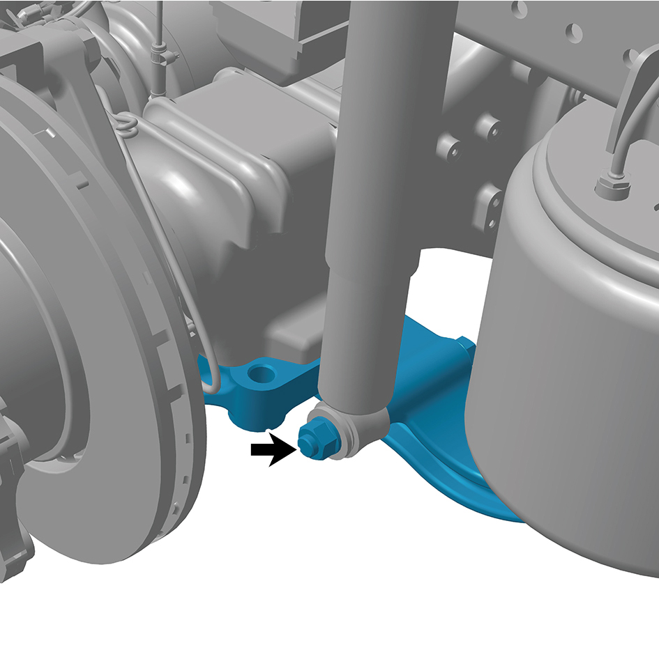
Torque:405.5 +/- 37 (ft lbs)
4
Install the rear spring U-bolt.
5
Install the longitudinal thrust rod assembly.
6
Install the shock absorber assembly (rear).
7
Install the drive wheel (rear right).
8
Lower the rear end of the vehicle.
8.7.3.5 Replacement of X-shaped Control Arm Assembly (front)
Assembly (front)
Removal Procedures
1
Removal the fifth wheel assembly.
2
Remove the corrugated plate.
3
Remove 4 fixing nuts of the X-shaped control arm
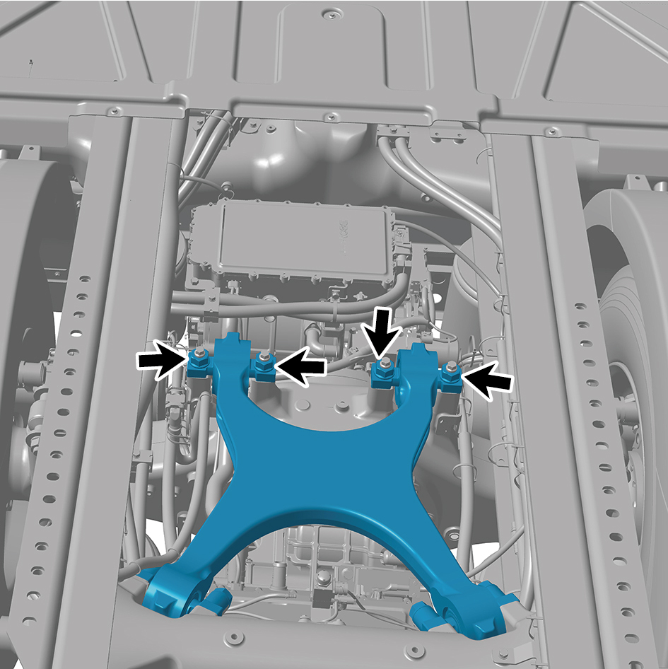
assembly (front).
4
Remove 4 fixing bolts of the X-shaped control arm
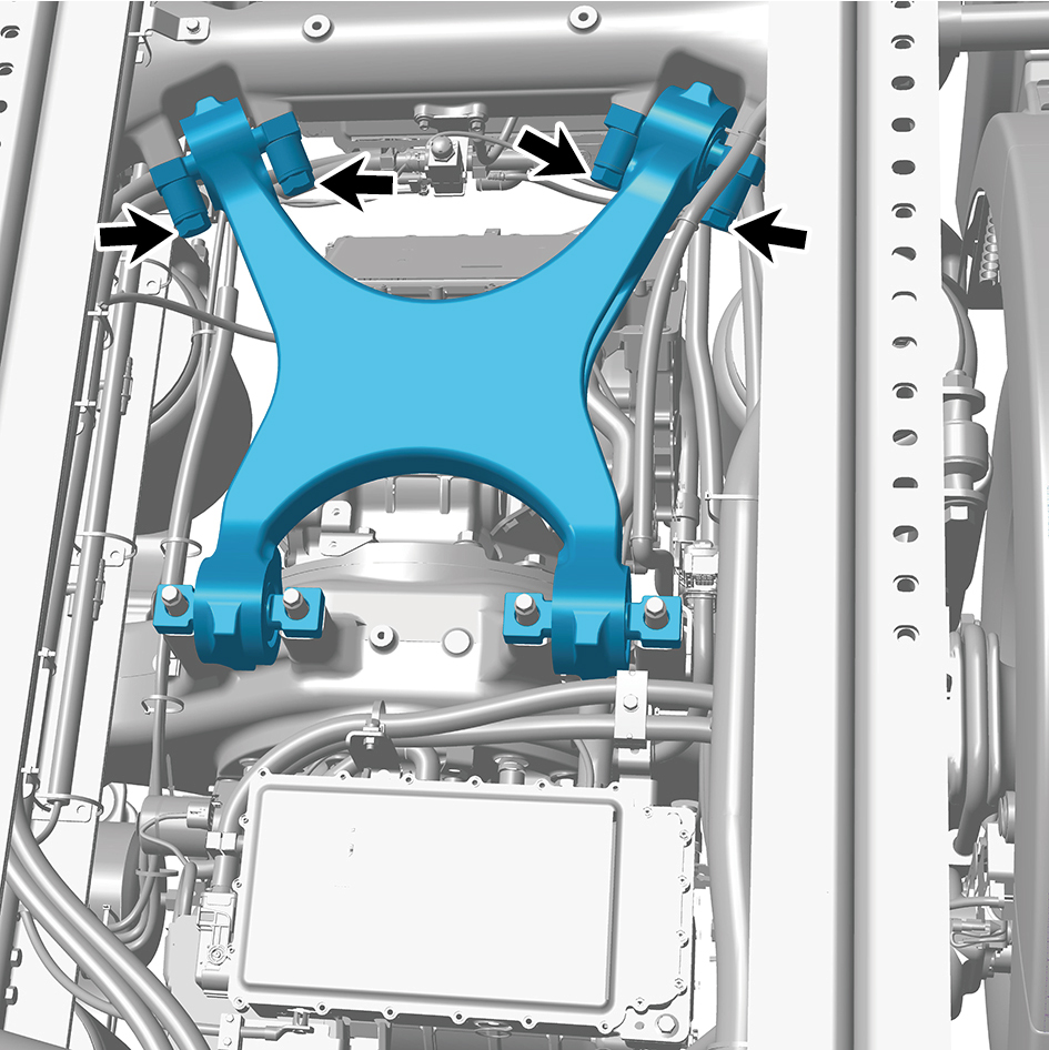
assembly (front).
5
Remove the X-shaped control arm assembly (front).
Installation Procedures
1
Move the X-shaped control arm assembly (front) to the
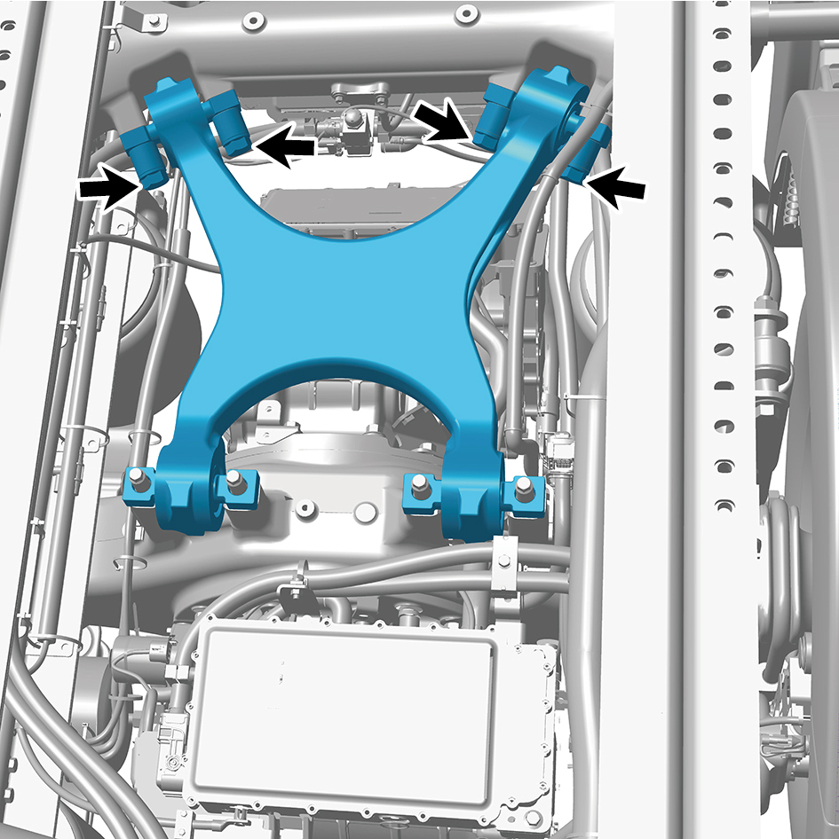
mounting position.
2
Install 4 fixing bolts of the X-shaped control arm assembly
(front).
Torque:516 +/- 37 (ft lbs)
caution
Simply screw in the thread and tighten it after the
other end is secured.
3
Install 4 fixing nuts of the X-shaped control arm assembly
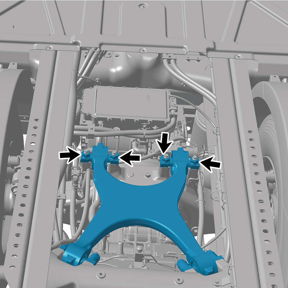
(front).
Torque:516 +/- 37 (ft lbs)
4
Install the corrugated plate.
5
Install the fifth wheel assembly.
8.7.3.6 Replacement of X-shaped Control Arm Assembly (rear)
Assembly (rear)
Removal Procedures
1
Open the door.
2
Open the front flip cover plate.
3
Disconnect the battery negative cable.
caution
power down the high-voltage system before
disconnecting the negative pole of the storage
battery.
4
Remove the dual channel module assembly.
5
Remove 4 fixing nuts of the X-shaped control arm
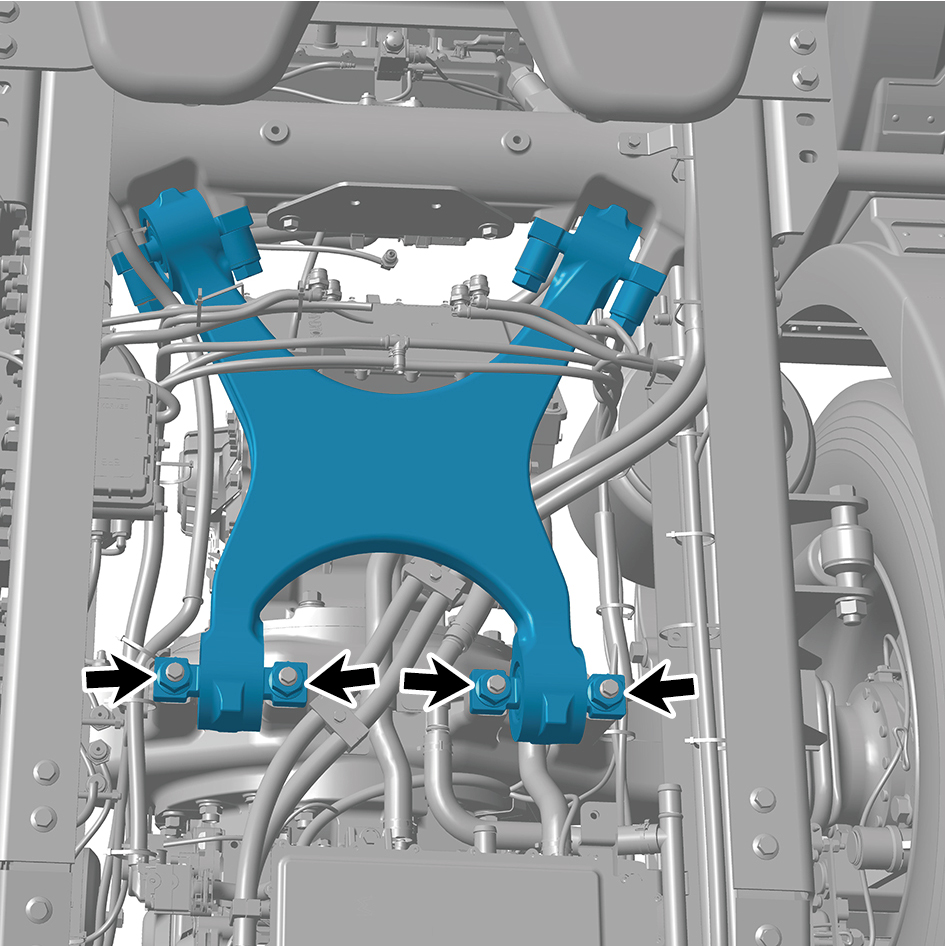
assembly (rear).
6
Remove 4 fixing bolts of the X-shaped control arm
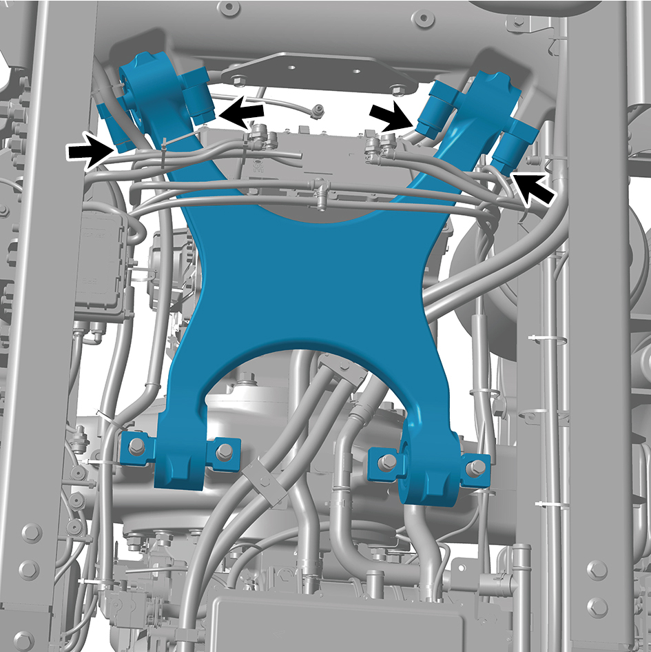
assembly (rear).
7
Remove the X-shaped control arm assembly (rear).
Installation Procedures
1
Move the X-shaped control arm assembly (rear) to the
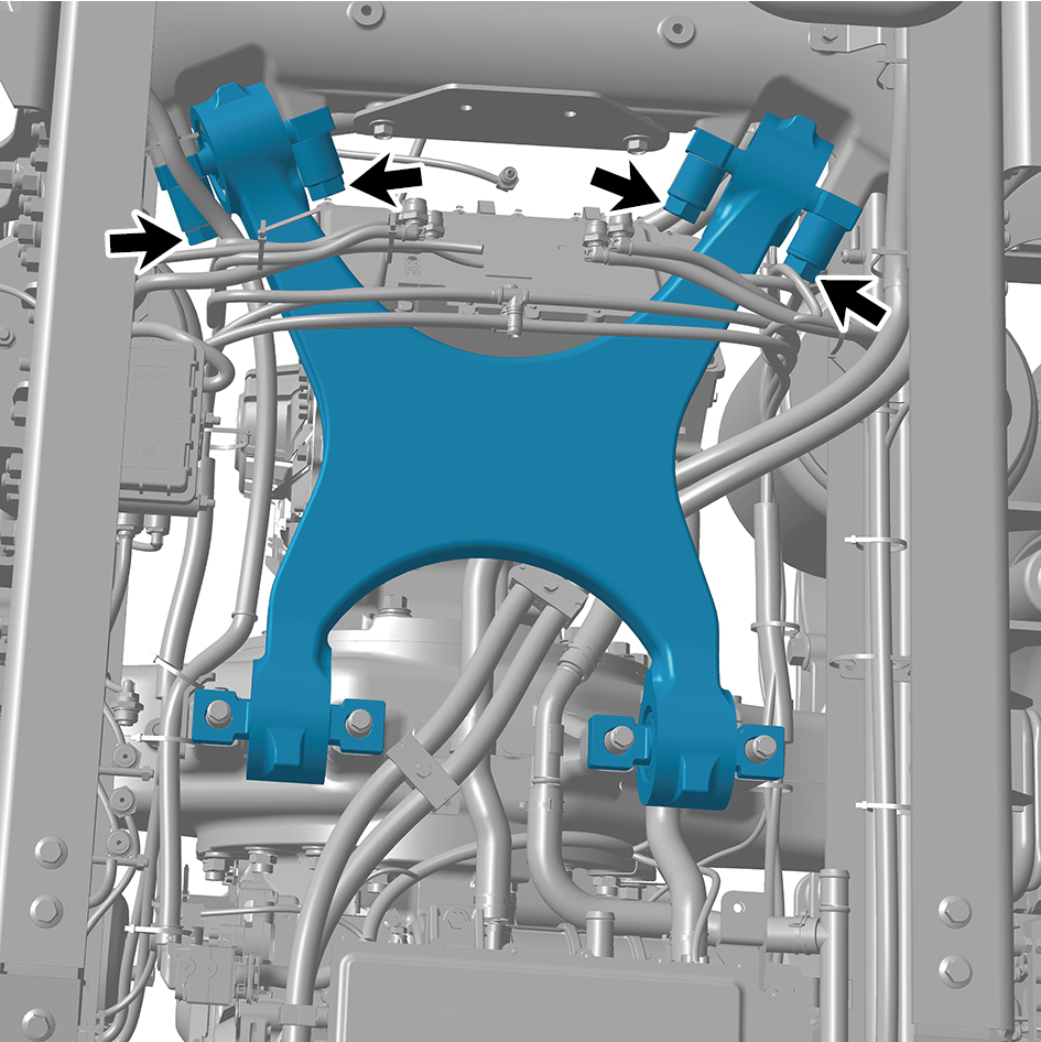
mounting position.
2
Install 4 fixing bolts of the X-shaped control arm assembly
(rear).
Torque: 516 +/- 37 (ft lbs)
caution
Simply screw in the thread and tighten it after the
other end is secured.
3
Install 4 fixing nuts of the X-shaped control arm assembly
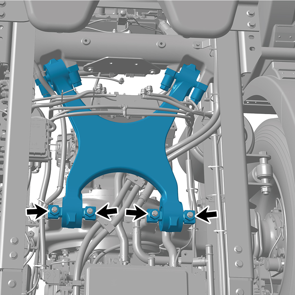
(rear).
Torque: 516 +/- 37 (ft lbs)
4
Install the dual channel module assembly.
5
Connect the battery negative cable.
6
Close the front flip cover plate.
7
Close the door.
8.7.3.7 Replacement of Shock Absorber Assembly (rear)
Assembly (rear)
Removal Procedures
1
Jack the rear end of the vehicle.
2
Remove the drive wheel (front left).
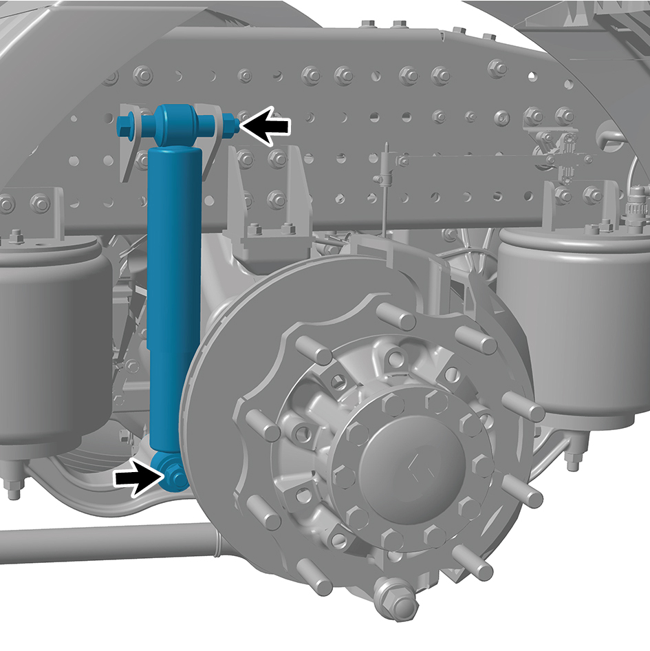
3
Remove 2 fixing bolts and nuts of the shock absorber
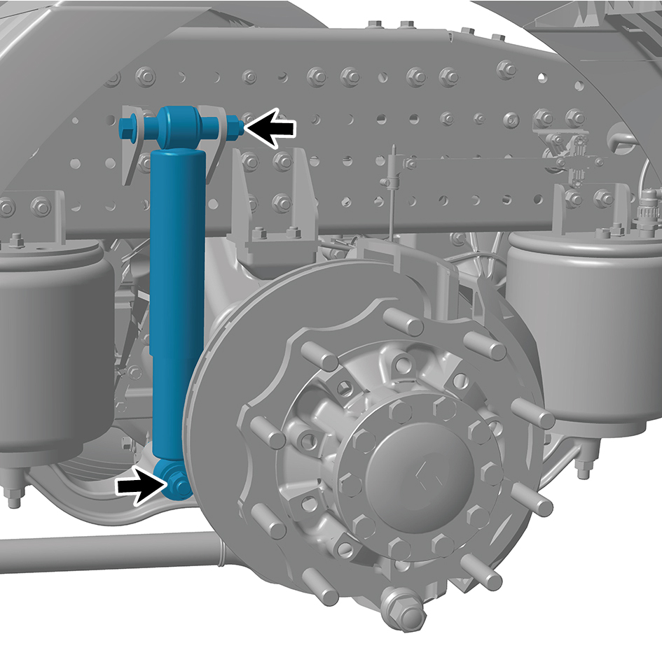
assembly (rear).
4
Remove the shock absorber assembly (rear).
Installation Procedures
1
Move the shock absorber assembly (rear) to the mounting
position.
2
Install 2 fixing bolts and nuts of the shock absorber
assembly (rear).
Torque:516 +/- 37 (ft lbs)
3
Install the drive wheel (left front).
4
Lower the rear end of the vehicle.
8.7.3.8 Replacement of Shock Absorber Bracket
Bracket
Removal Procedures
1
Jack the rear end of the vehicle.
2
Remove the drive wheel (front left).
3
Remove 1 fixing bolt and nut connecting the shock
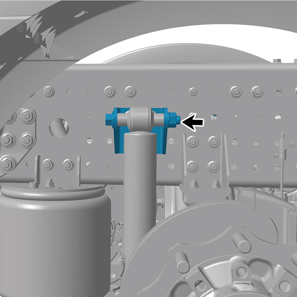
absorber bracket to the shock absorber assembly (rear),
and separate the shock absorber assembly (rear).
4
Remove 4 fixing bolts and nuts of the shock absorber
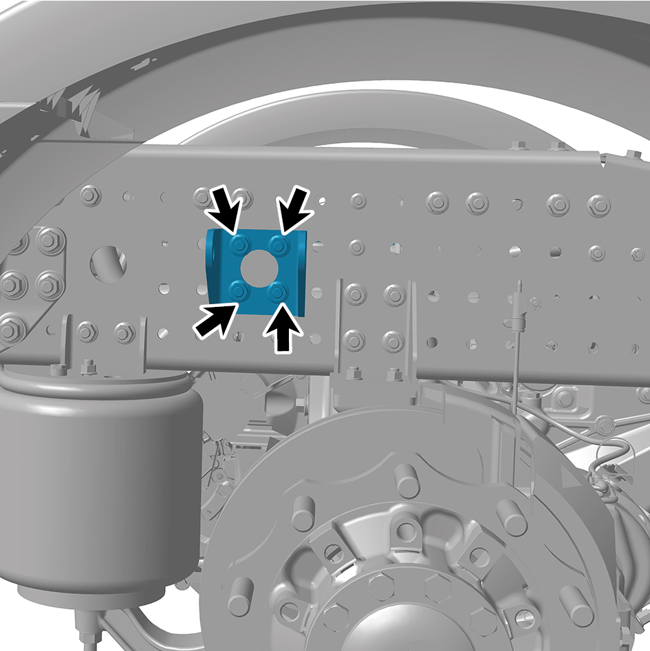
bracket.
5
Remove the shock absorber bracket.
Installation Procedures
1
Move the shock absorber bracket to the mounting
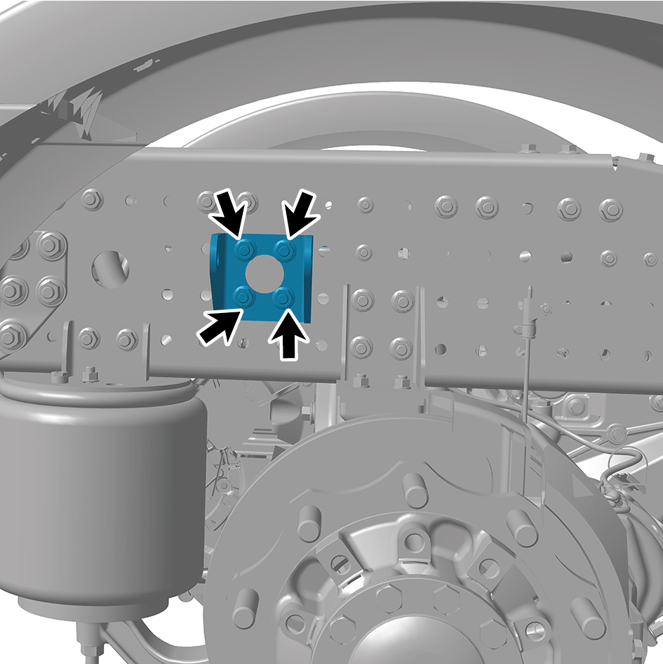
position.
2
Install 4 fixing bolts and nuts of the shock absorber
bracket.
Torque: 155 +/- 14.5 (ft lbs)
3
Install 1 fixing bolt and nut connecting the shock absorber
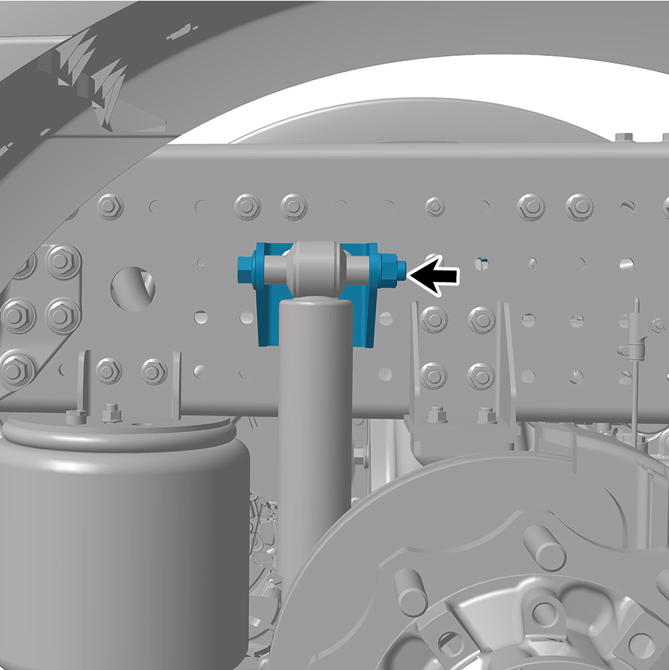
bracket to the shock absorber assembly (rear), and
separate the shock absorber assembly (rear).
Torque:405.5 +/- 37 (ft lbs)
4
Install the drive wheel (left front).
5
Lower the rear end of the vehicle.
8.7.3.9 Replacement of Limit Buffer Assembly
Removal Procedures
1
Remove 4 fixing bolts and nuts of the limit buffer
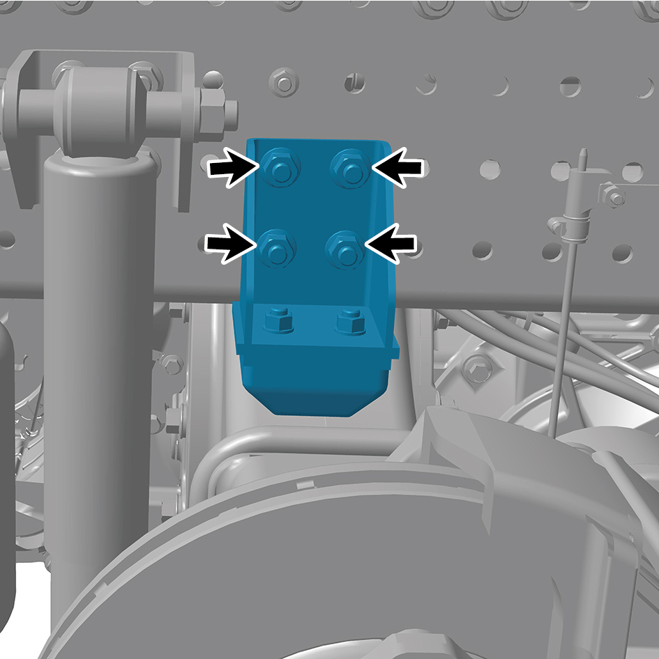
assembly.
2
Remove the limit buffer assembly.
Installation Procedures
1
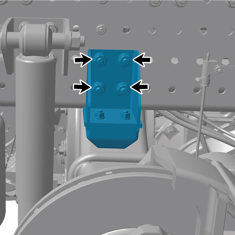
Move the limit buffer assembly to the mounting position.
2
Install 4 fixing bolts and nuts of the limit buffer assembly.
Torque:155 +/- 14.75 (ft lbs)
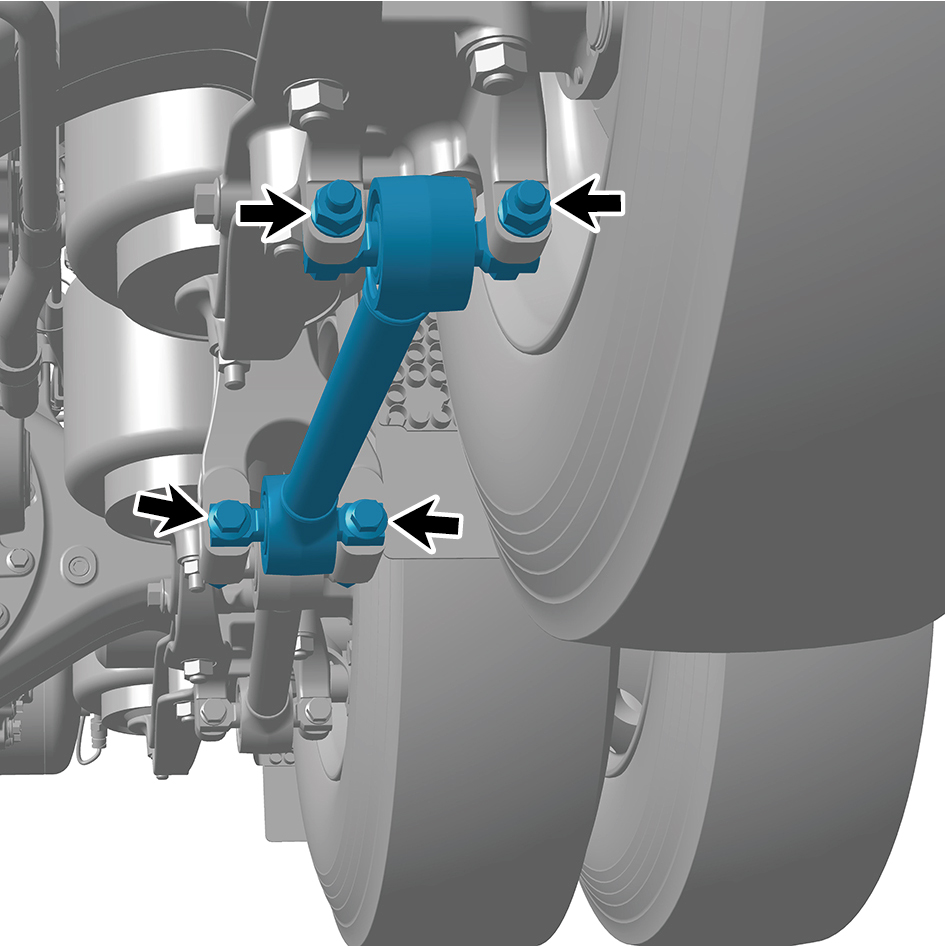
8.7.3.10 Replacement of Longitudinal Thrust Rod Assembly
Rod Assembly
Removal Procedures
1
Jack the rear end of the vehicle.
2
Remove the drive wheel (front left).
3
Remove 4 fixing bolts and nuts of the longitudinal thrust
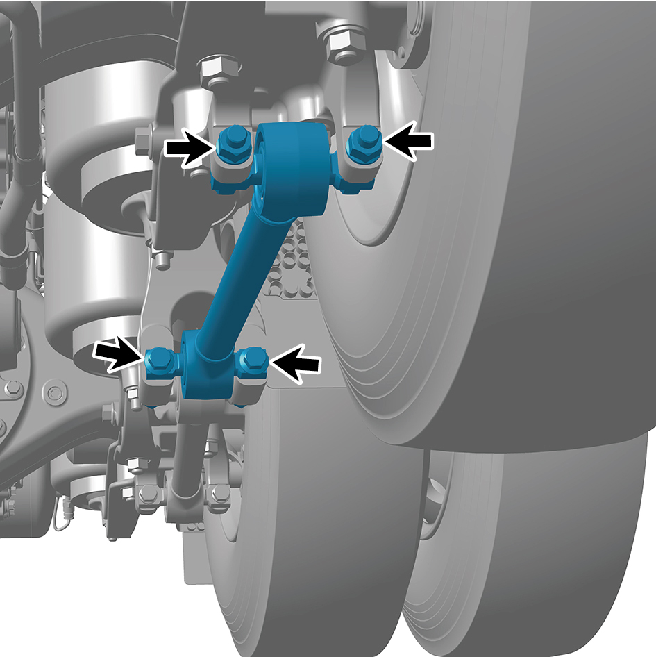
rod assembly.
4
Remove the longitudinal thrust rod assembly.
Installation Procedures
1
Move the longitudinal thrust rod assembly to the mounting
position.
2
Install 4 fixing bolts and nuts of the longitudinal thrust rod
assembly.
Torque:405.5 +/- 37 (ft lbs)
3
Install the drive wheel (left front).
4
Lower the rear end of the vehicle.
8.7.3.11 Replacement of Thrust Bar Bracket
Removal Procedures
1
Jack the rear end of the vehicle.
2
Remove the drive wheel (rear left).
3
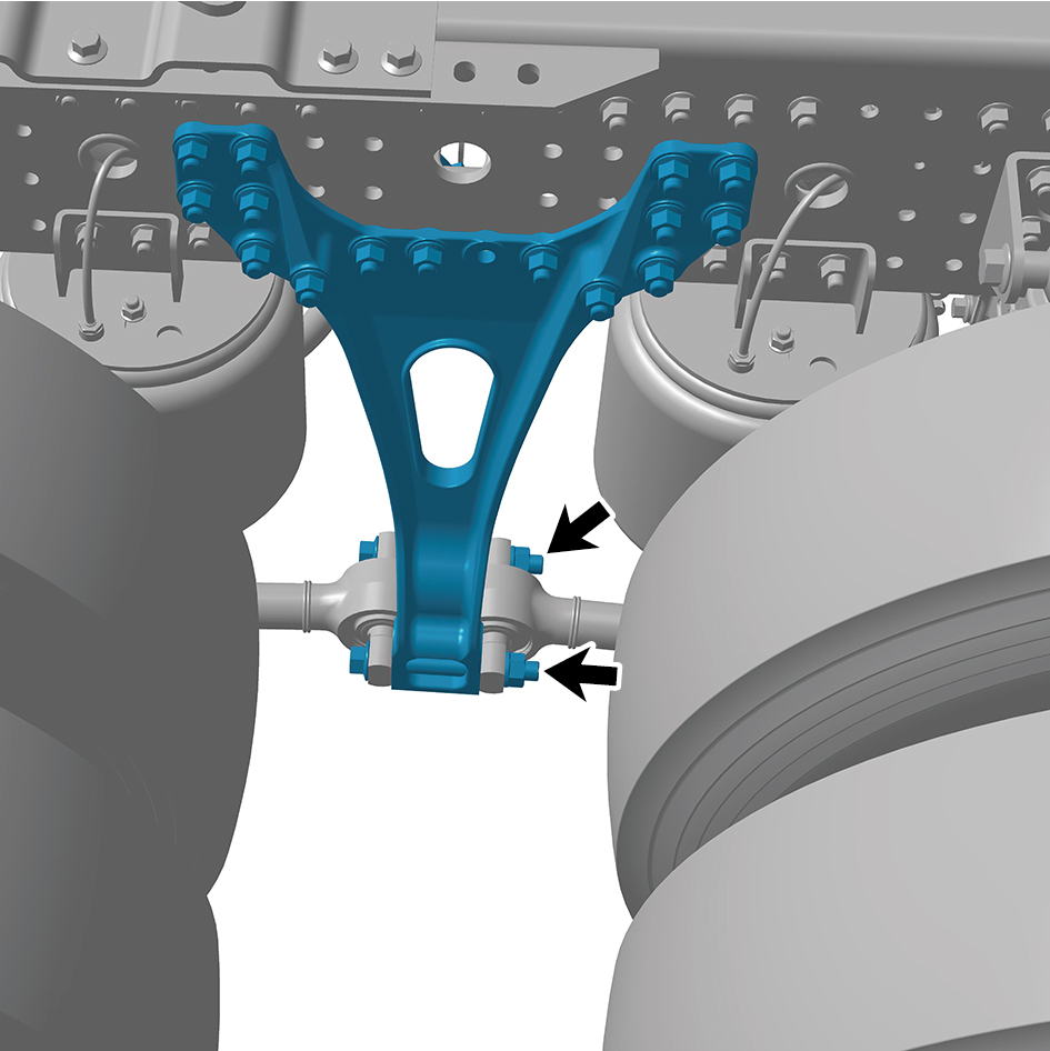
Remove 2 fixing bolts and nuts connecting the thrust bar
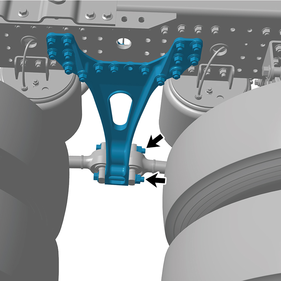
bracket to the thrust bar.
4
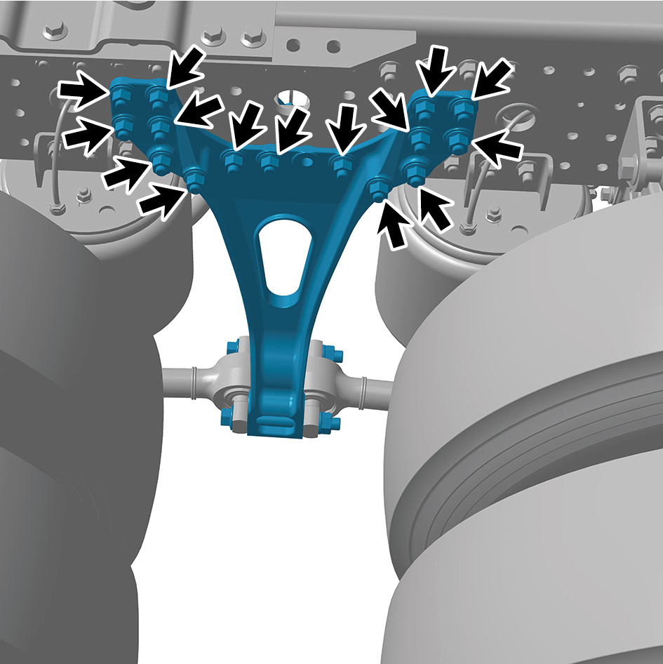
Remove 15 fixing bolts and nuts of the thrust bar bracket.
5
Remove the thrust bar bracket.
Installation Procedures
1
Move the thrust bar bracket to the mounting position.
2
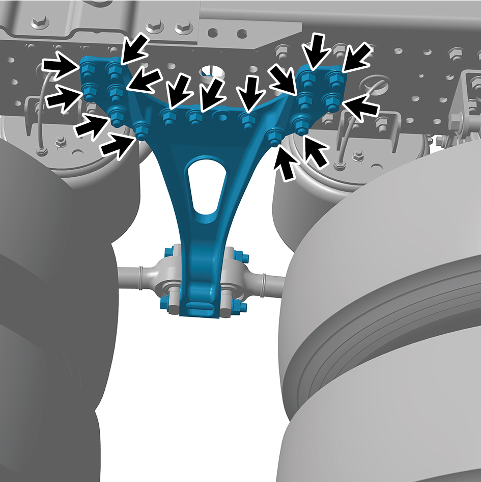
Install 15 fixing bolts and nuts of the thrust bar bracket.
Torque:234.5 +/- 18.5 (ft lbs)
3
Install 2 fixing bolts and nuts connecting the thrust bar
bracket to the thrust bar.
Torque: 405.5 +/- 37 (ft lbs)
4
Install the drive wheel (rear left).
5
Lower the rear end of the vehicle.
8.7.3.12 Replacement of Rear Spring U-bolt
Removal Procedures
1
Jack the rear end of the vehicle.
2
Remove the drive wheel (rear left).
3
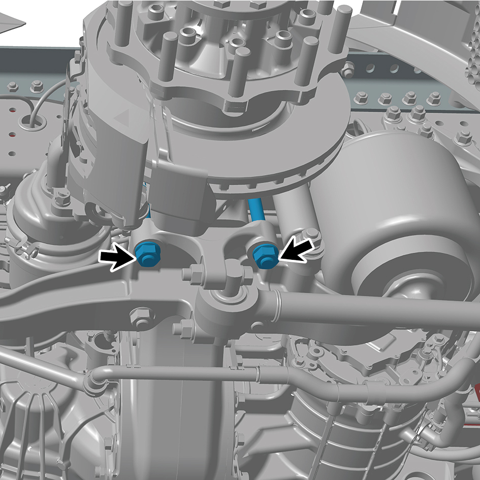
Remove 2 fixing nuts of the rear spring U-bolt.
4
Remove the rear spring U-bolt.
Installation Procedures
1
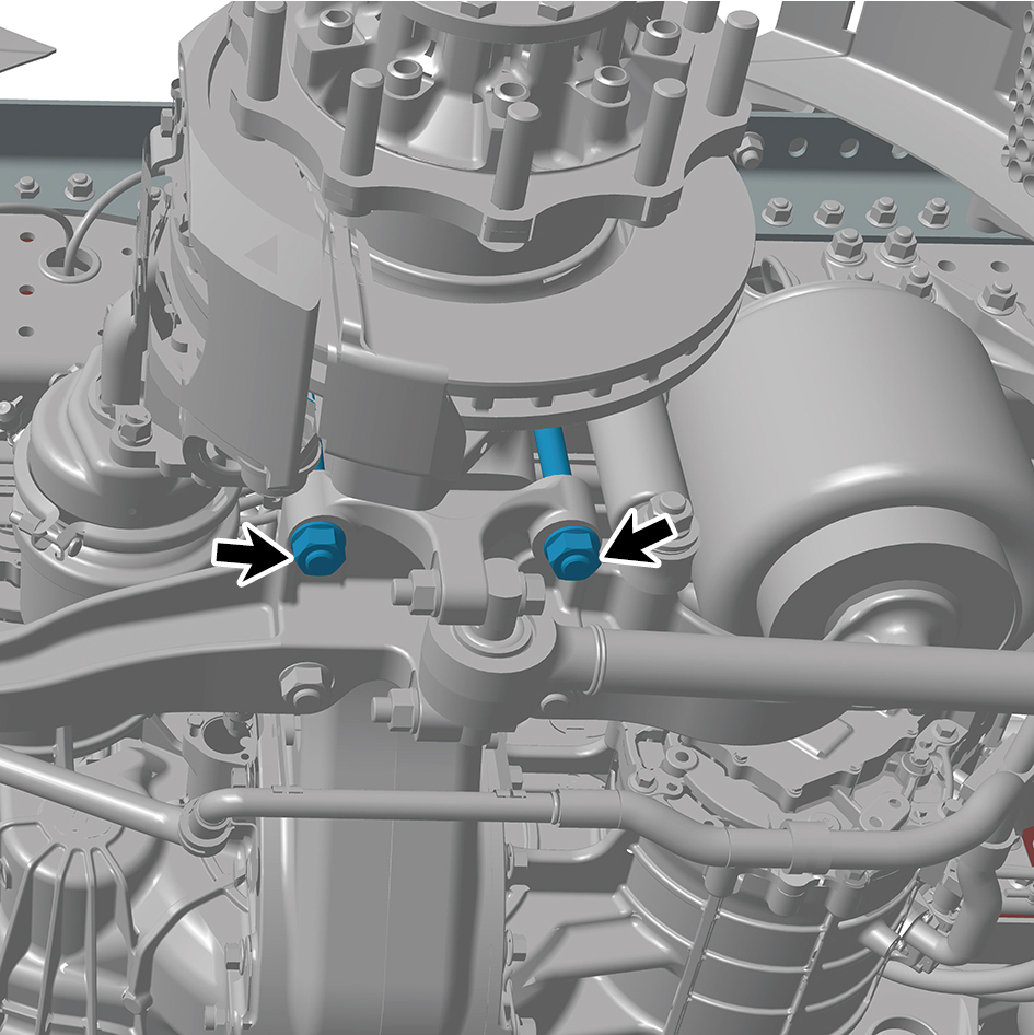
Move the rear spring U-bolt to the mounting position.
2
Install 2 fixing nuts of the rear spring U-bolt.
Torque: 516 +/- 37 (ft lbs)
3
Install the drive wheel (rear left).
4
Lower the rear end of the vehicle.