← Back to Contents
8 Chassis / 8.6 Front Suspension Device | PDF pages 1860-1926
8.6 Front Suspension Device
8.6 Front Suspension Device
8.6.1 Specifications
8.6.1.1 Fastener Specifications
Range Of Torque
Fastener Specifications
Specifications
Foot Pounds of Torque (ft lbs)
The fixing bolts connecting the upper
420 +/- 22 (ft lbs) (Apply sealant)
M20
swing arm assembly and the upper
frame of the subframe
The fixing bolts connecting the lower
420 +/- 22 (ft lbs) (Apply sealant)
M20
arm assembly and the frame on the
subframe
The fixing nut connecting the front air
spring assembly and the mounting plate
40.5 +/- 3.5 (ft lbs)
M12
on the front spring
The fixing bolt connecting the front air
spring assembly and the left steering
199 +/- 18.5 (ft lbs)
M18
knuckle bracket assembly
The fixing nut connecting the front
shock absorber assembly to the lower
66 +/- 7.5 (ft lbs)
M16
mounting bracket of the front shock
absorber
The fixing nut connecting the front
shock absorber assembly and the
66 +/- 7.5 (ft lbs)
M16
mounting bracket on the front shock
absorber
The fixing bolt connecting the front
405 +/- 18.5 (ft lbs) (Apply sealant)
M20
brake assembly and the steering
knuckle
The fixing nut connecting the upper end
of the steering knuckle and the left
800 +/- 37 (ft lbs)
M40
steering knuckle bracket assembly
The fixing nut connecting the lower end
of the steering knuckle and the left
89 +/- 7.5 (ft lbs
M40
steering knuckle bracket assembly
Wheel hub flange fixing bolt
243 +/- 18.5 (ft lbs) (Apply sealant)
M16
The fixing nut connecting the brake
133 +/- 7.5 (ft lbs)
M16
chamber to the front brake assembly
The fixing bolt connecting the steering
627 +/- 37 (ft lbs) (Apply sealant)
M22
arm and the steering knuckle
The fixing nut connecting the steering
254 +/- 11 (ft lbs)
M24
arm and the tie rod
Range Of Torque
Fastener Specifications
Specifications
Foot Pounds of Torque (ft lbs)
The fixing nut connecting the wheel hub
442.5 +/- 37 (ft lbs)
M45
bearing unit and the steering knuckle
Upper end cover and steering knuckle
147.5 +/- 14.75 (ft lbs)
/
Lower end cover steering knuckle
147.5 +/- 14.75 (ft lbs)
/
8.6.1.2 Technical Parameters
Brake system parameters
Unit Adjustment
Item
Numerical Value
Remark
Brake lining - outside - new
31
Disc
Minimum thickness of brake lining -
11
Disc
outside
Brake lining - inside - new
30
Disc
Minimum thickness of brake lining -
10
Disc
inside
Brake caliper type
Floating
Disc
45
Disc
Thickness of brake disc - new
Scrap thickness of brake disc
37
Disc
8.6.2 Decomposition Diagram
8.6.2.1 Decomposition Diagram
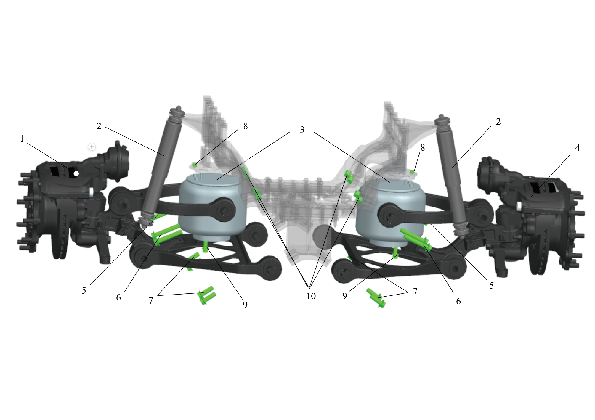
1.
6.
Left Front Wheel End Assy
Upper Swing Arm Mounting Bolt(Rear)
7.
2.
Inner Pivot Nut
Front Shock Absorber
3.
8.
Front Airspring
Nut M12x1.5 (Spiralock) In New Energy Vehicles
4.
9.
Right Front Wheel End Assy
Hexagon Flange Bolt
5.
10.
Upper Swing Arm Mounting Bolt(Rear)
Nut M20x1.5 (Spiralock)
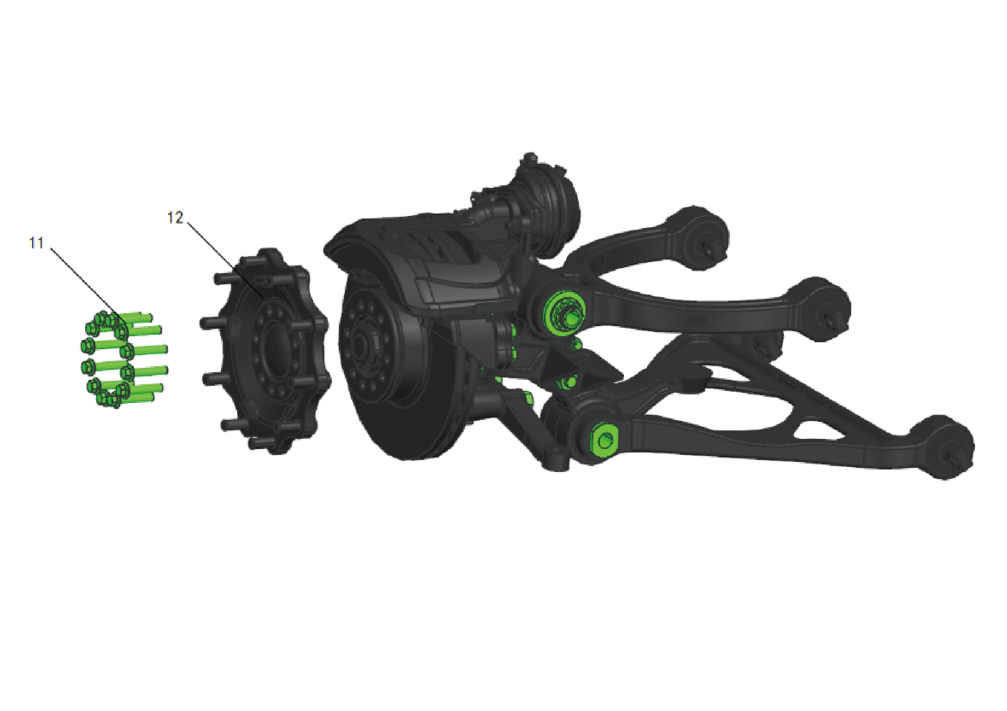
11.
Flange Bolt
12.
Hub Flange Assembly
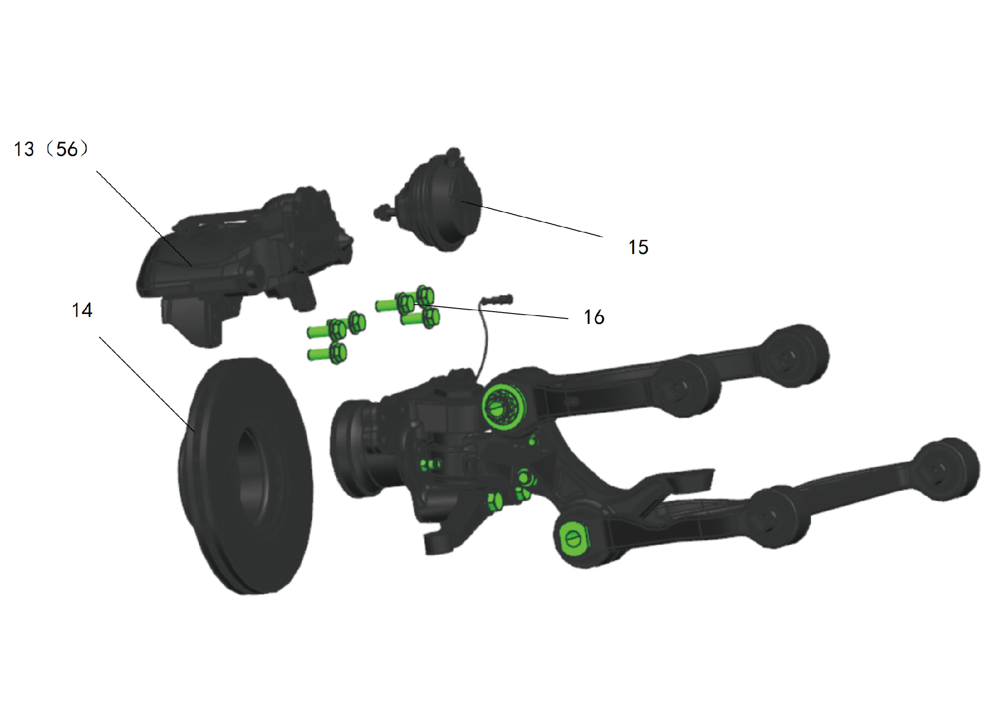
13.
16.
Brake Bolts
Brake Caliper Assy-Lh Frt
14.
Brake Disc
56.
Brake Caliper Assy-Rh Frt
15.
Brake Chamber
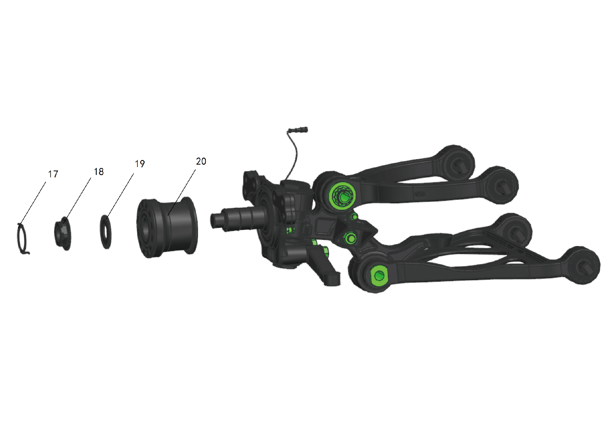
17.
19.
Snap Ring
Stop Washer
18.
Hub Lock Nut
20.
Hub Bearing Units
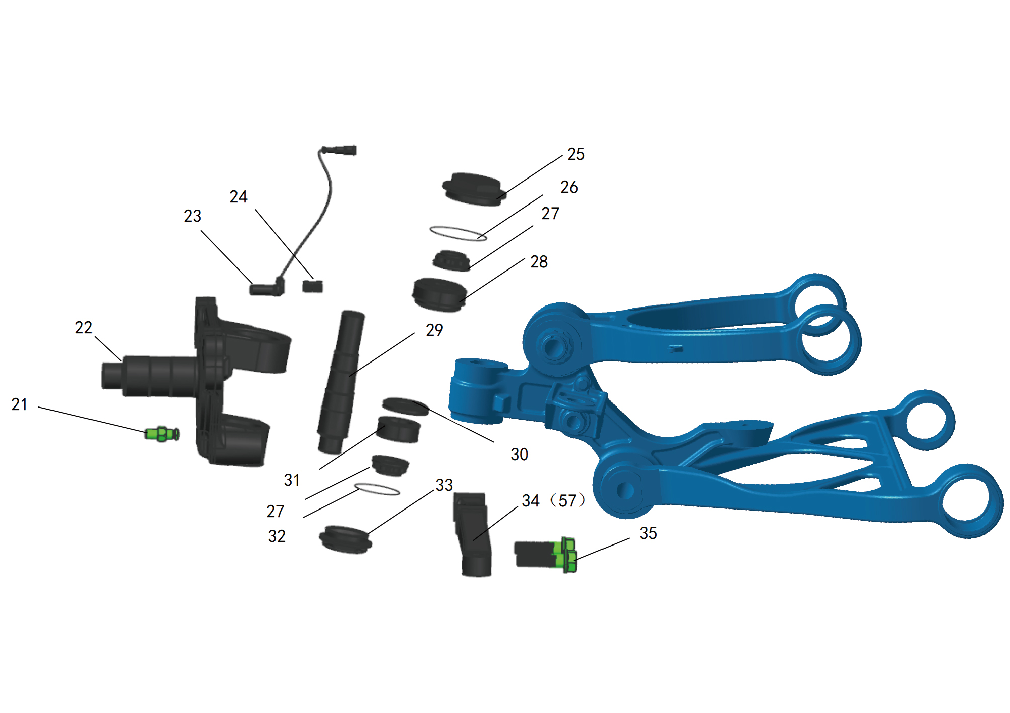
21.
29.
Kingpin
Limit Screw And Nut
22.
30.
Steering Knuckle
Sealing Rings
23.
31.
ABS Sensor
Spherical Bearings
24.
32.
SensorAbs Sensor Bushing
Lower O-Ring
25.
33.
Upper End Cap
Lower End Cap
26.
34.
Upper O-Ring
Steering Arm_Left
27.
Kingpin Lock Nut
35.
Hexagon Flange Bolt
57.
28.
Thrust Bearings
Right Steering Arm
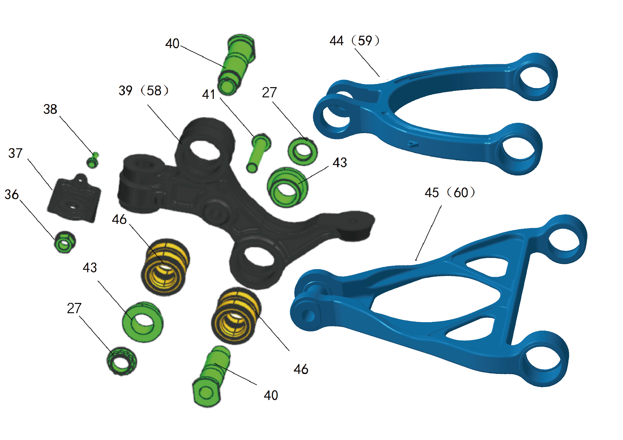
36.
43.
Stabilizer Rod Tie Rod Support Fixing Nut
Outer Pivot Self-Aligning Washer In New Energy
Vehicles
37.
44.
Upper Arm_Left
Lower Mounting Bracket_Shock Absorber
38.
Hexagon Flange Bolt
45.
Swing Arm Assy-Lh Lor
39.
46.
Knuckle Carrier-Lh
Outer Bearing Assembly of Swing Arm In New Energy
Vehicles
40.
58.
Outer Pivot_Lower Arm
Right Steering Knuckle Bracket Assembly In New
Rnergy Vehicles
41.
Damper Bracket Fixing Bolt
59.
Swing Arm - Right
42.
Kingpin Lock Nut
60.
Swing Arm Assy-Lor Rh
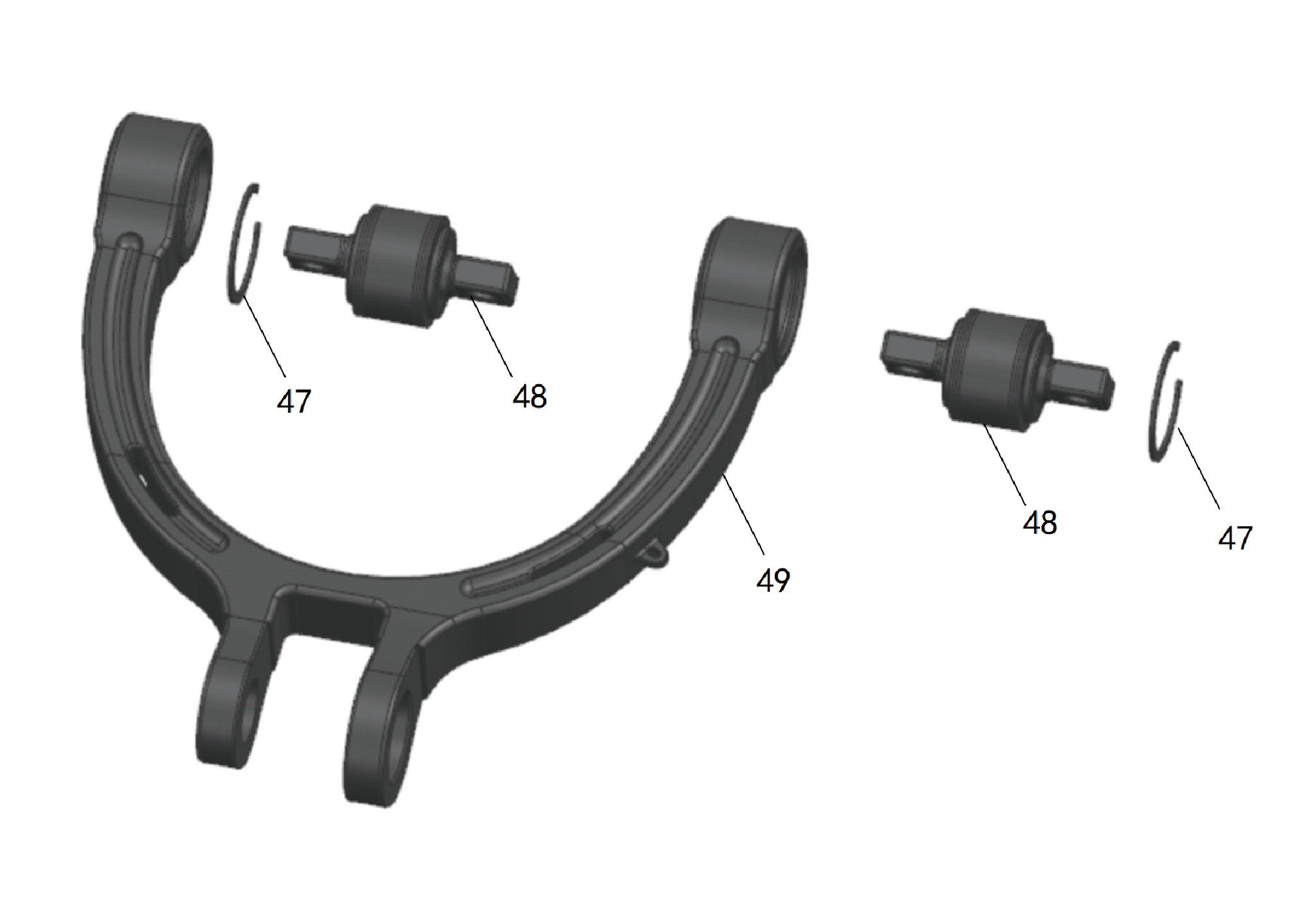
47.
49.
Snap Ring
Left Upper Swing Arm Body In New Energy Vehicles
48.
Ball Joint Bushing In New Energy Vehicles
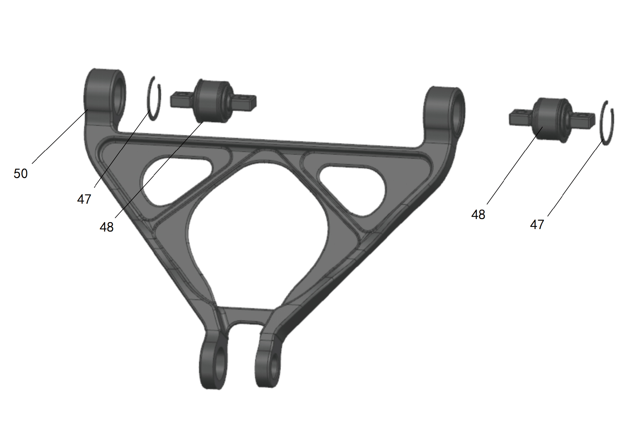
47.
50.
Snap Ring
Left Lower Swing Arm Body In New Energy Vehicles
48.
Ball Joint Bushing In New Energy Vehicles
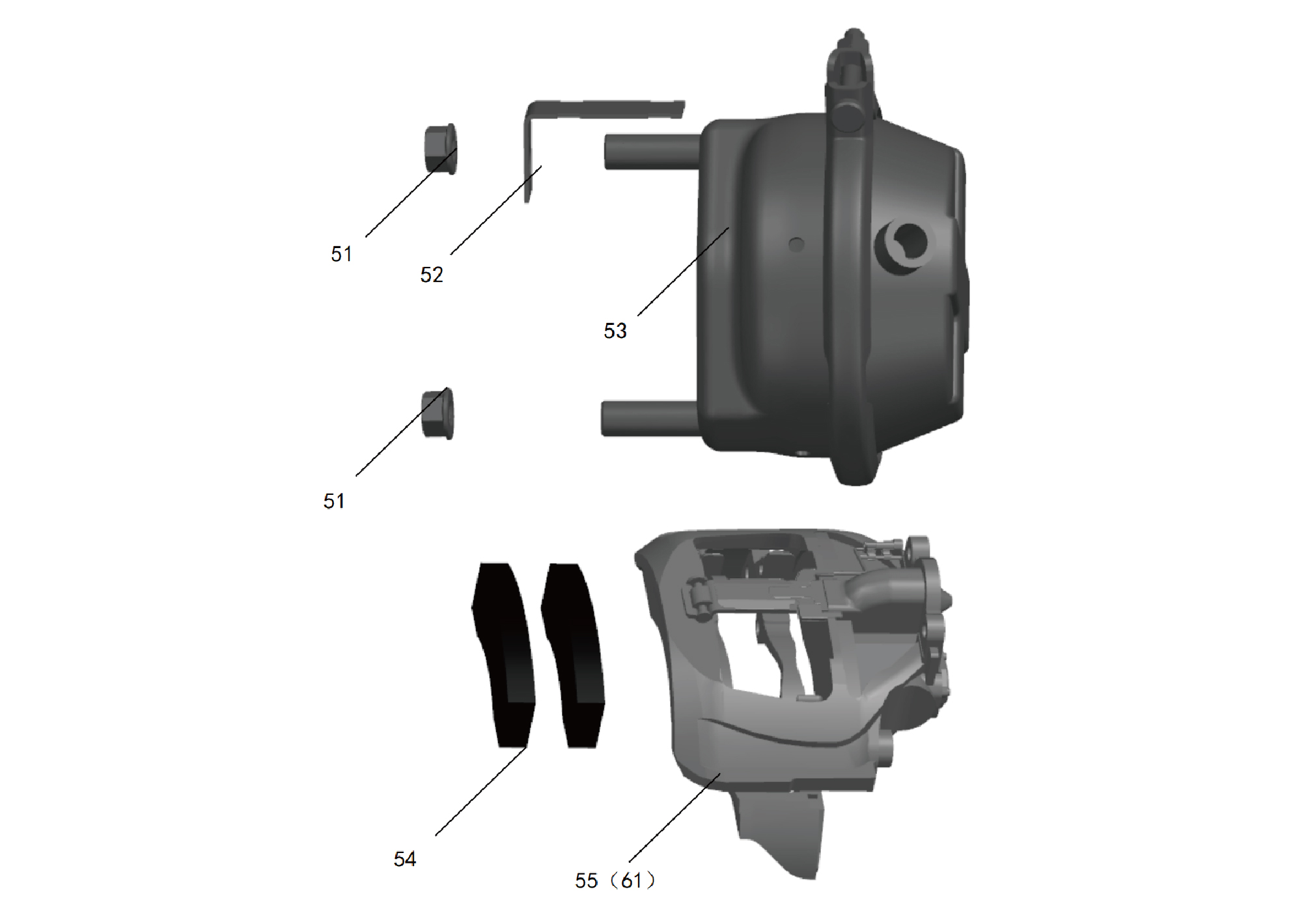
51.
54.
Friction Plate
Brake Chamber Fixing Nut In New Energy Vehicles
55.
52.
Brake Chamber Gasket In New Energy Vehicles
Left Front Brake Caliper Body
53.
61.
Brake Chamber Body In New Energy Vehicles
Brake Caliper Assy-Rh Frt
8.6.3 Dismantling and Installation
8.6.3.1 Replacement of Left Front Brake Assembly
Assembly
Removal Procedures
1
Release air pressure from the brake system.
2
Open the door.
3
Open the front flip cover plate.
4
Disconnect the battery negative cable.
caution
power down the high-voltage system before
disconnecting the negative pole of the storage
battery.
5
Jack the front end of the vehicle.
6
Remove the guide wheel (left).
7
Remove the brake chamber (left).
8
Disconnect 1 harness connector of the left front brake
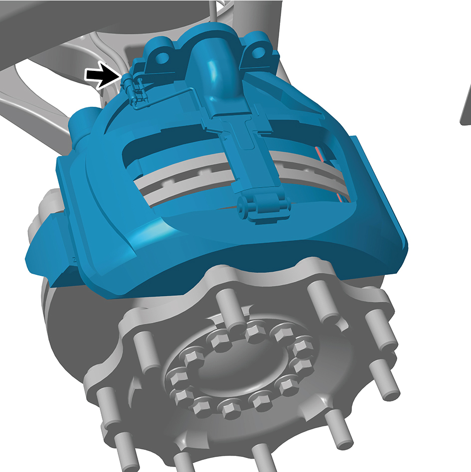
assembly.
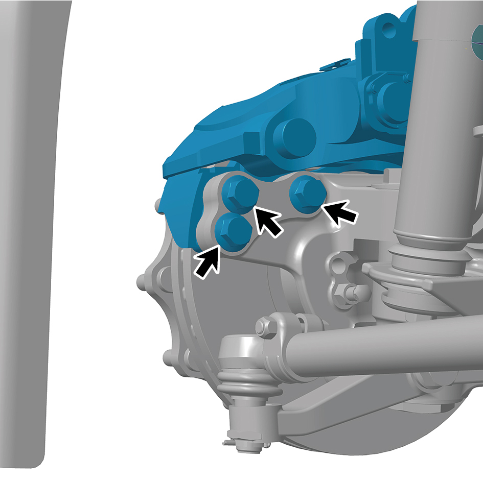
9
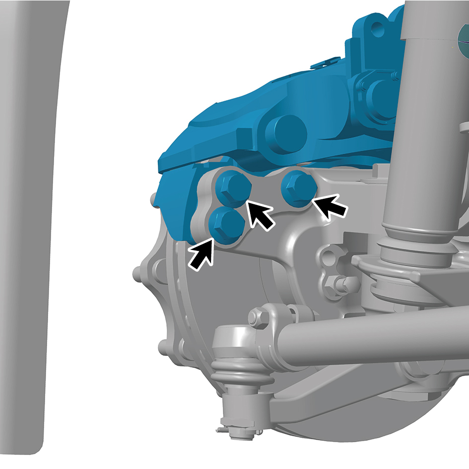
Remove 6 fixing bolts of the left front brake assembly, and
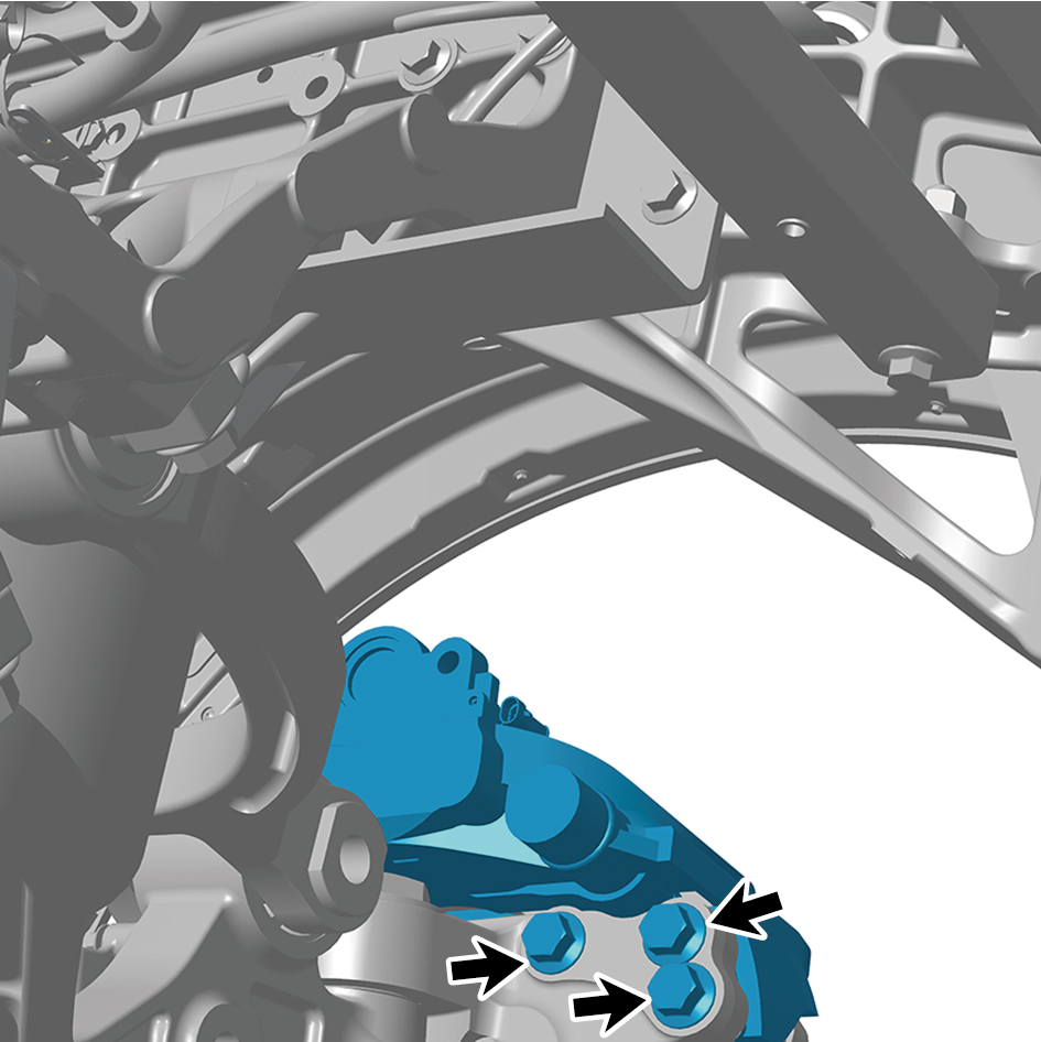
remove the left front brake assembly.
Installation Procedures
1
Move the left front brake assembly to the mounting
position.
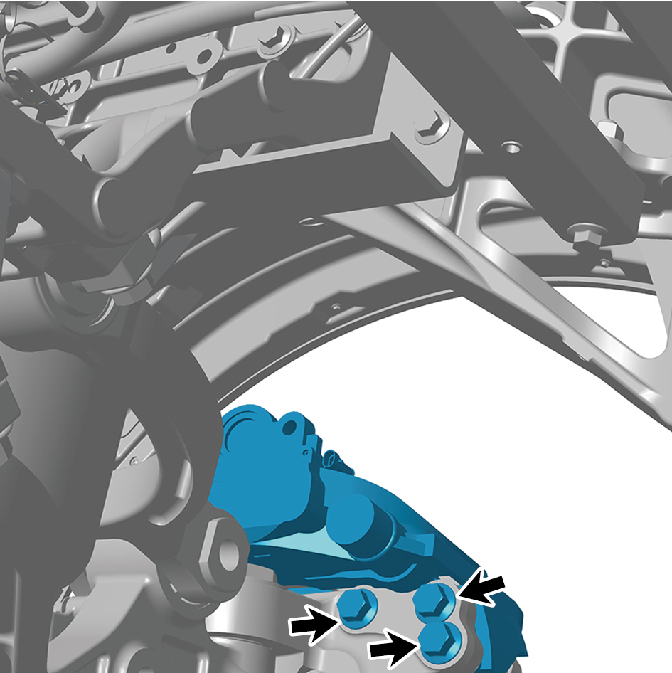
2
Install 6 fixing bolts of the left front brake assembly.
Torque: 406 +/- 18.5 (ft lbs)
3
Connect 1 harness connector of the left front brake
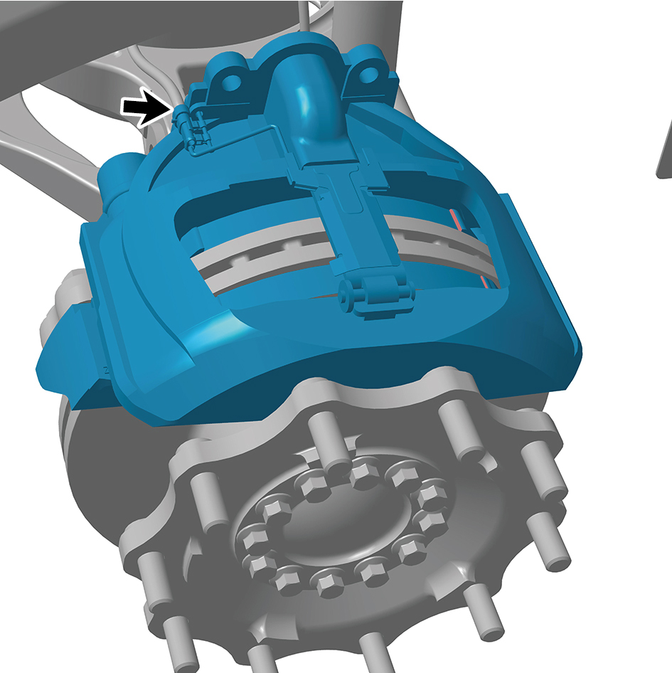
assembly.
caution
The harness is firmly connected following the
principal of "insert until a click is heard for
confirmation".
4
Install the brake chamber (left).
5
Install the guide wheel (left).
6
Lower the front end of the vehicle.
7
Connect the battery negative cable.
8
Close the front flip cover plate.
9
Close the door.
8.6.3.2 Replacement of Left Front Brake Body
Removal Procedures
1
Release air pressure from the brake system.
2
Open the door.
3
Open the front flip cover plate.
4
Disconnect the battery negative cable.
caution
power down the high-voltage system before
disconnecting the negative pole of the storage
battery.
5
Jack the front end of the vehicle.
6
Remove the guide wheel (left).
7
Remove the brake chamber (left).
8
Remove the friction plate (left).
9
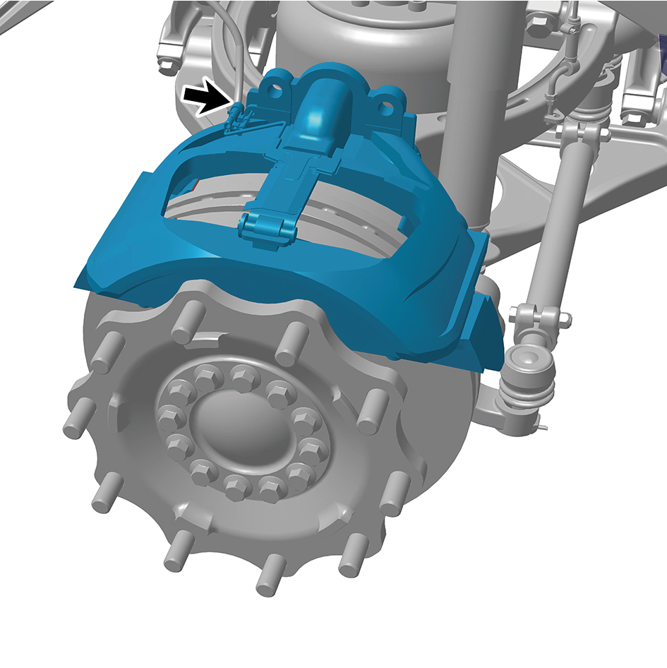
Disconnect 1 harness connector of the left front brake
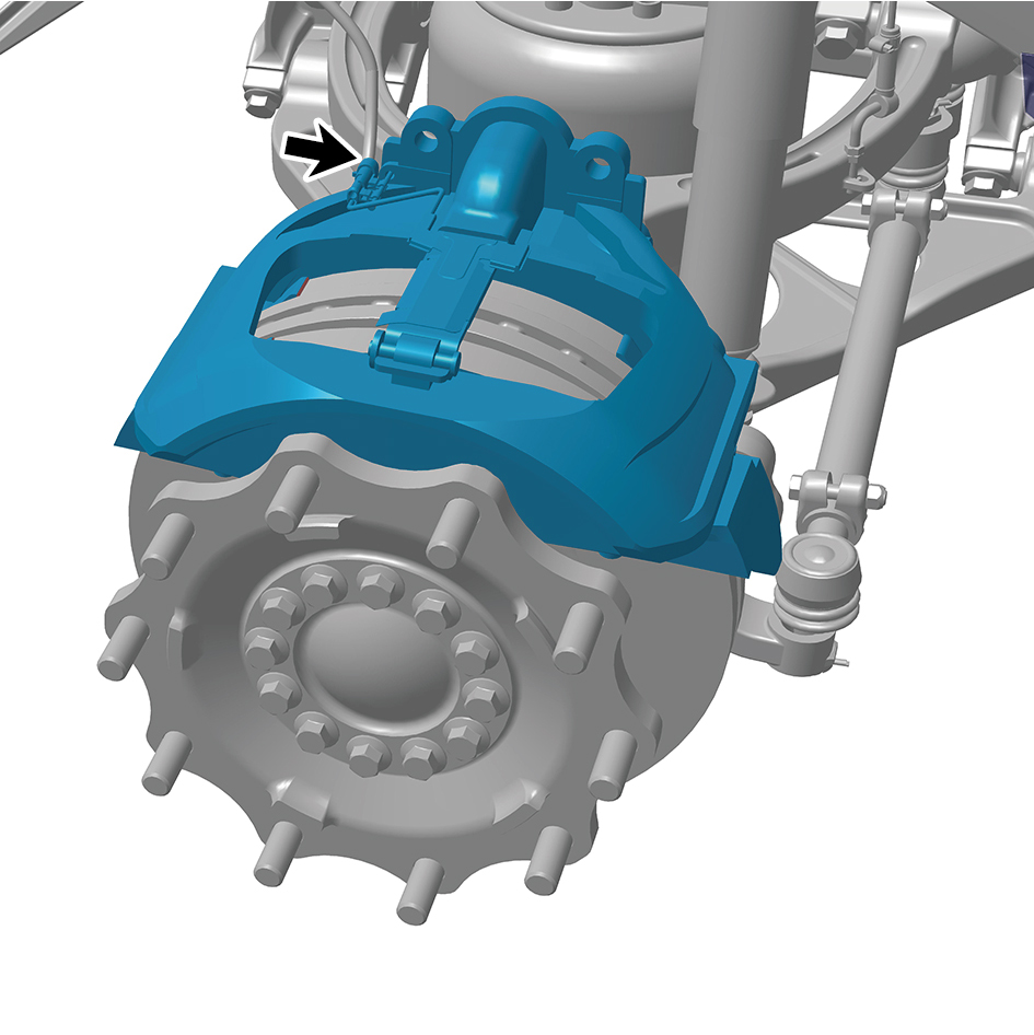
body.
10
Remove 6 fixing bolts of the left front brake body and
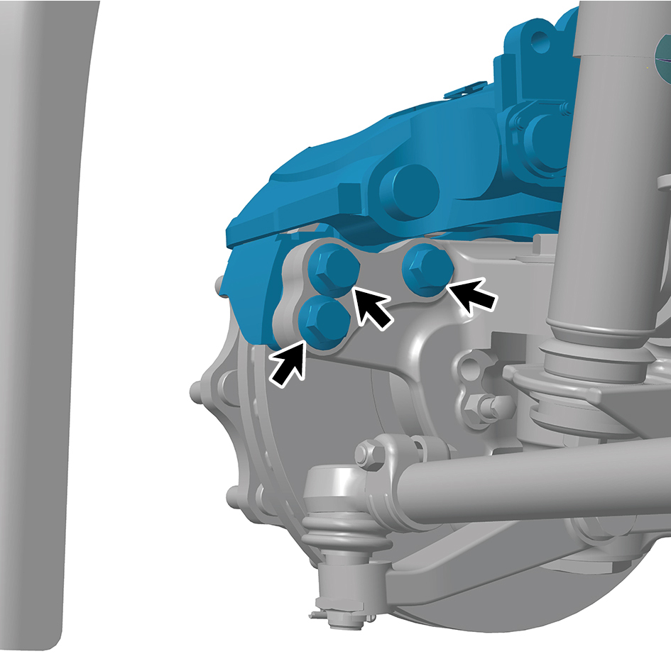
remove the left front brake body.
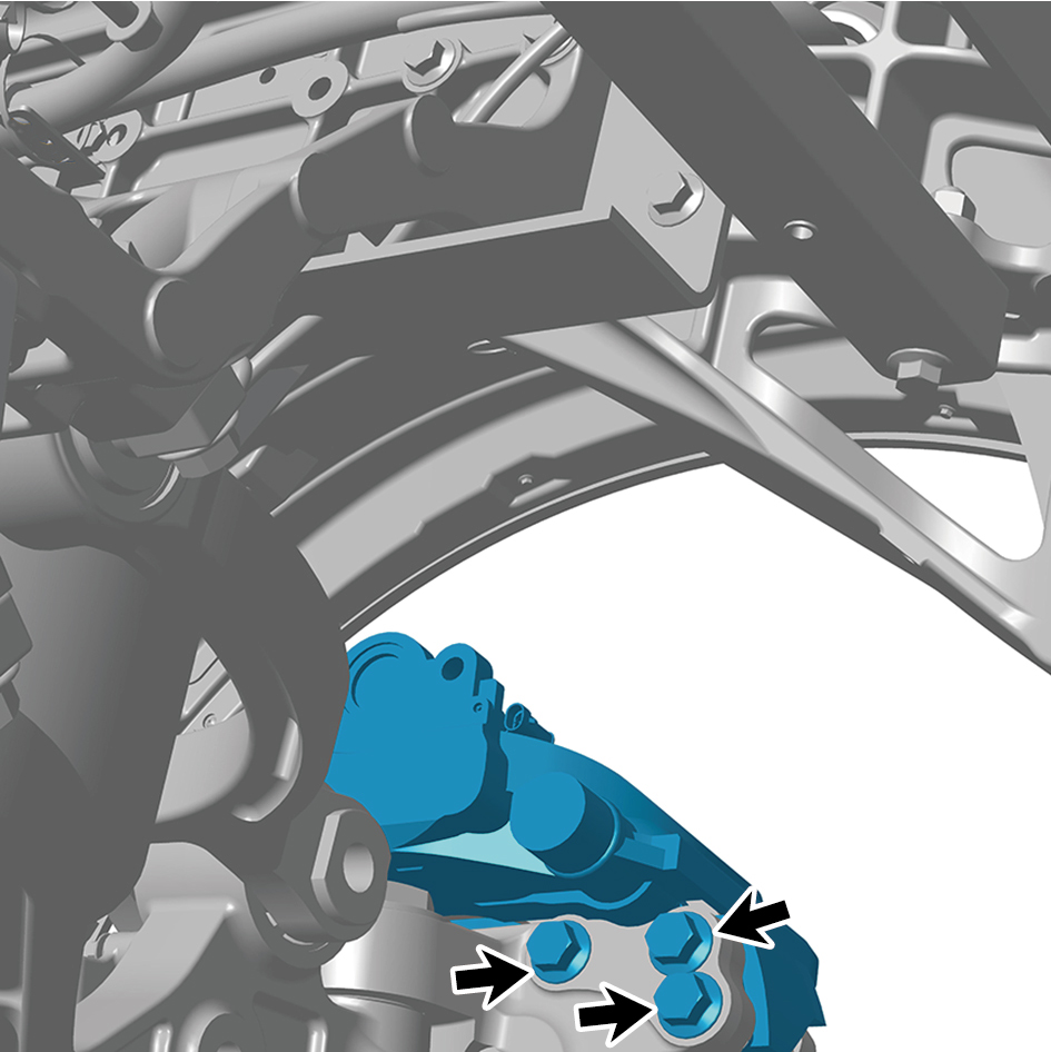
Installation Procedures
1
Move the left front brake body to the mounting position.
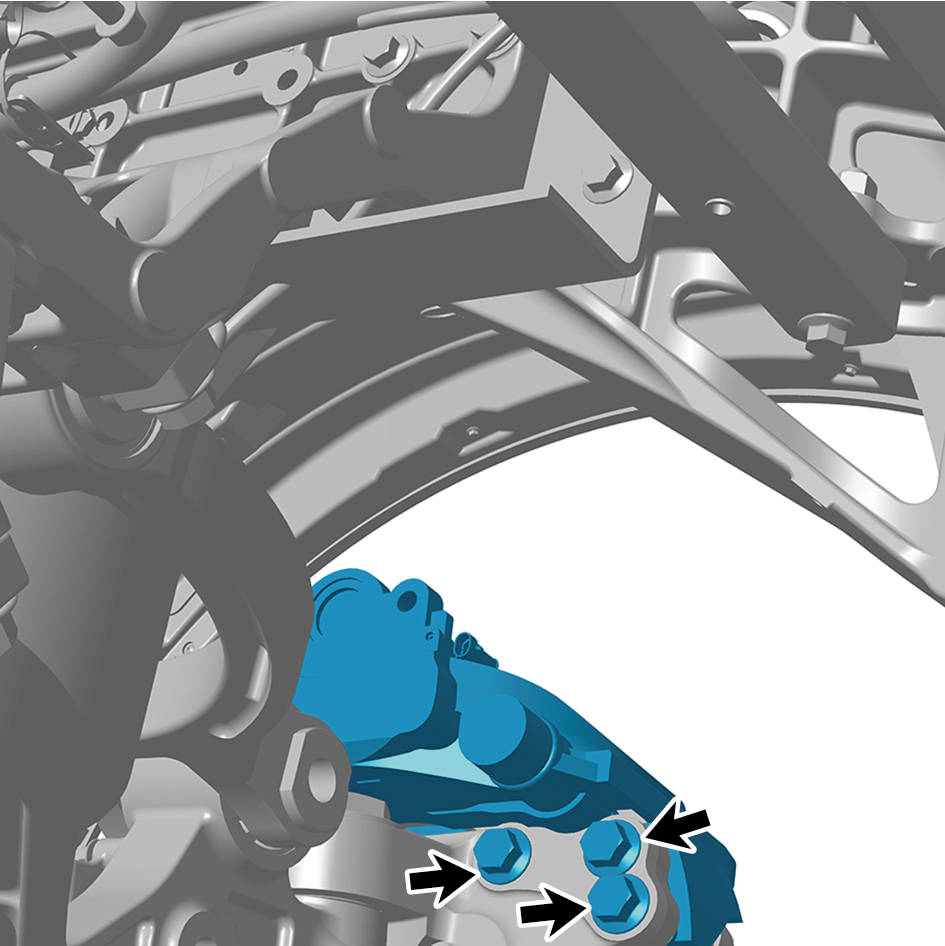
2
Install 6 fixing bolts of the left front brake body.
Torque: 405 +/- 18.5 (ft lbs)
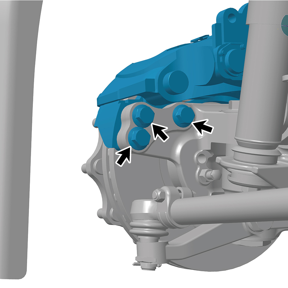
3
Connect 1 harness connector of the left front brake body.
caution
The harness is firmly connected following the
principal of "insert until a click is heard for
confirmation".
4
Install the friction plate (left).
5
Install the left front brake assembly.
6
Install the brake chamber (left).
7
Install the guide wheel (left).
8
Lower the front end of the vehicle.
9
Connect the battery negative cable.
10
Close the front flip cover plate.
11
Close the door.
8.6.3.3 Replacement of Left Upper Swing Arm Assembly
Assembly
Removal Procedures
1
Release air pressure from the brake system.
2
Open the door.
3
Open the front flip cover plate.
4
Disconnect the battery negative cable.
caution
power down the high-voltage system before
disconnecting the negative pole of the storage
battery.
5
Jack the front end of the vehicle.
6
Remove the guide wheel (left).
7
Remove the front spring left upper mounting plate.
8
Remove the pressure sensor assembly.
9
Remove the front air spring assembly (left).
10
Remove the brake chamber (left).
11
Remove the front shock absorber assembly (left).
12
Remove the left front wheel end assembly.
13
Remove the swing arm outside pivot (left).
14
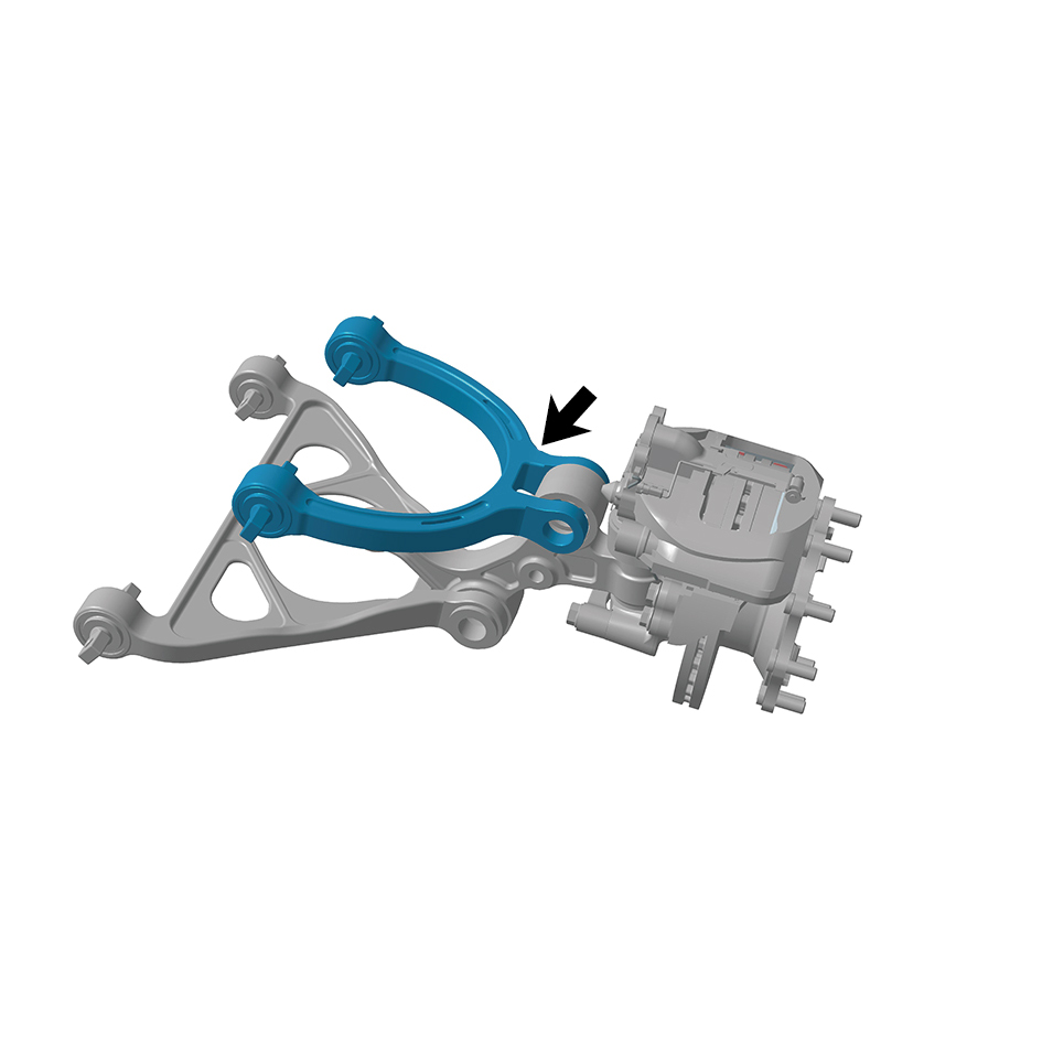
Remove the left upper swing arm assembly.
Installation Procedures
1
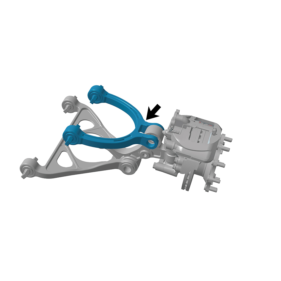
Install the left upper swing arm assembly.
2
Install the swing arm outside pivot (left).
3
Install the left front wheel end assembly.
4
Install the front shock absorber assembly (left).
5
Install the brake chamber (left).
6
Install the front air spring assembly (left).
7
Install the pressure sensor assembly.
8
Install the front spring left upper mounting plate.
9
Install the guide wheel (left).
10
Lower the front end of the vehicle.
11
Connect the battery negative cable.
12
Close the front flip cover plate.
13
Close the door.
caution
After part replacement, it is necessary to perform
four-wheel alignment.
8.6.3.4 Replacement of Left Lower Swing Arm Assembly
Assembly
Removal Procedures
1
Release air pressure from the brake system.
2
Open the door.
3
Open the front flip cover plate.
4
Disconnect the battery negative cable.
caution
power down the high-voltage system before
disconnecting the negative pole of the storage
battery.
5
Jack the front end of the vehicle.
6
Remove the guide wheel (left).
7
Remove the front spring left upper mounting plate.
8
Remove the pressure sensor assembly.
9
Remove the front air spring assembly (left).
10
Remove the brake chamber (left).
11
Remove the front shock absorber assembly (left).
12
Remove the left front wheel end assembly.
13
Remove the swing arm outside pivot (left).
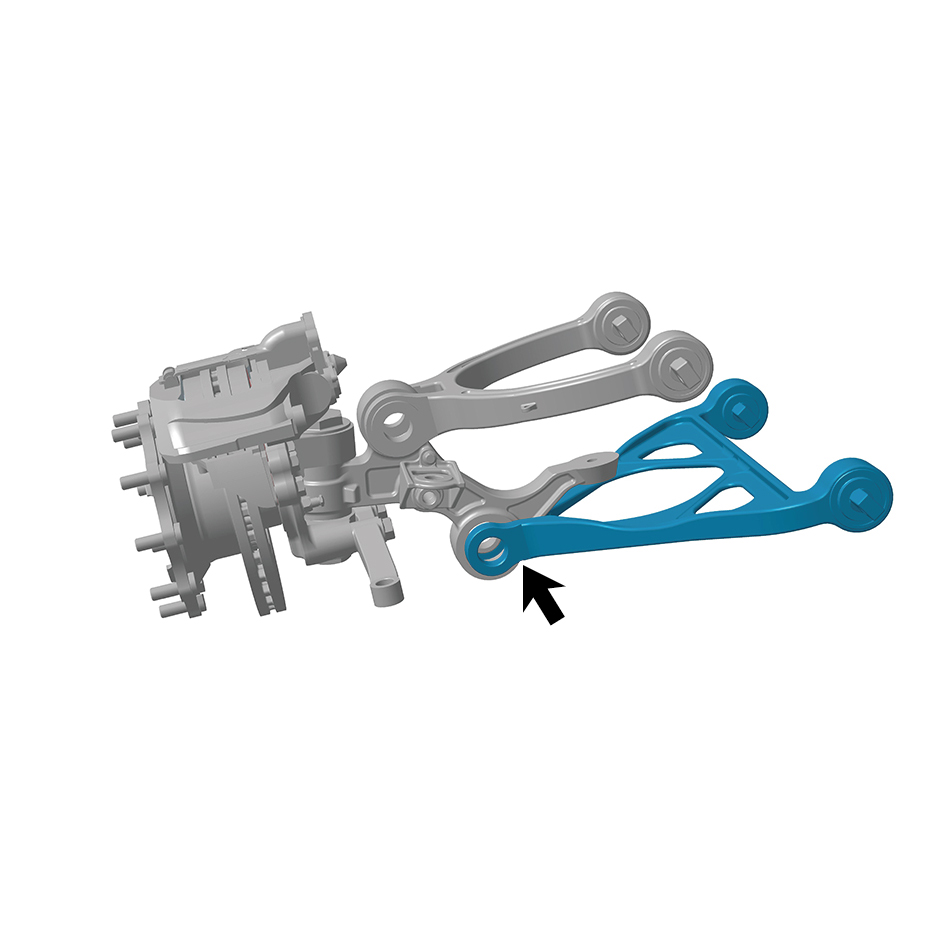
14
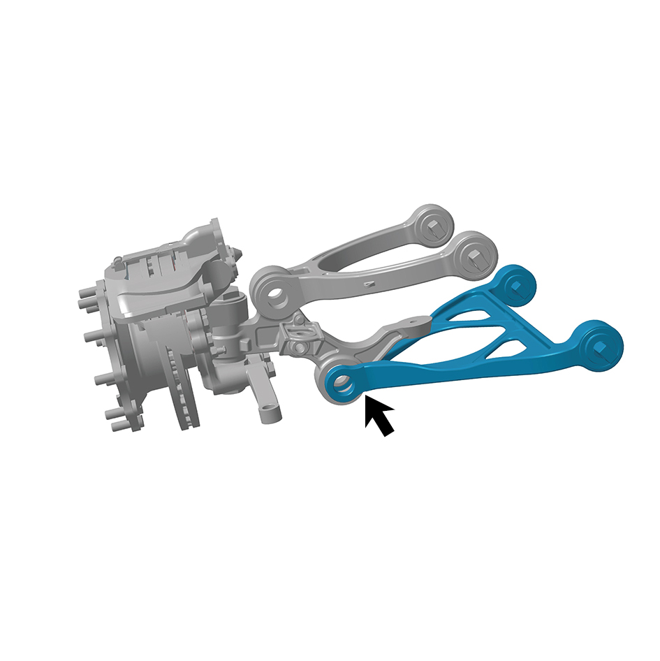
Remove the left lower swing arm assembly.
Installation Procedures
1
Install the left lower swing arm assembly.
2
Install the swing arm outside pivot (left).
3
Install the left front wheel end assembly.
4
Install the front shock absorber assembly (left).
5
Install the brake chamber (left).
6
Install the front air spring assembly (left).
7
Install the pressure sensor assembly.
8
Install the front spring left upper mounting plate.
9
Install the guide wheel (left).
10
Lower the front end of the vehicle.
11
Connect the battery negative cable.
12
Close the front flip cover plate.
13
Close the door.
8.6.3.5 Replacement of Left Steering Arm
Removal Procedures
1
Jack the front end of the vehicle.
2
Remove the guide wheel (left).
3
Remove 1 cotter pin at the connection between the tie rod
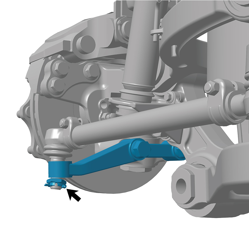
(left) and the left steering arm.
4
Remove 1 fixing nut at the connection between the tie rod
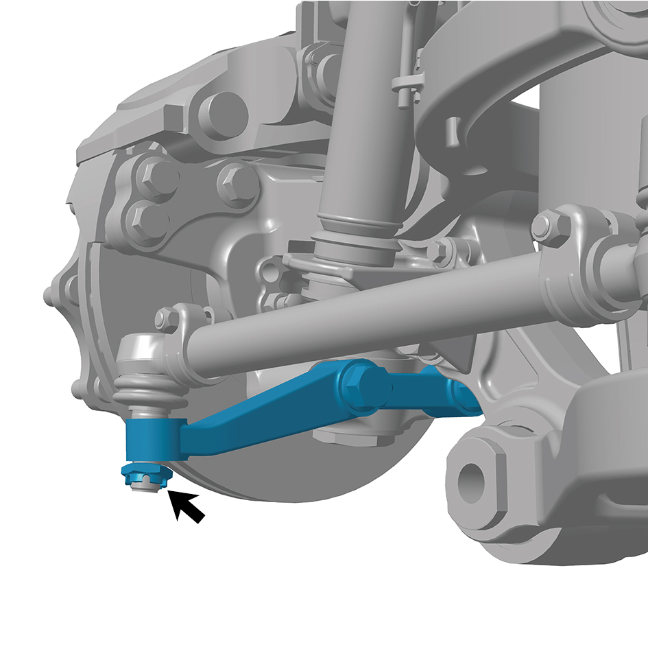
(left) and the left steering arm to separate the tie rod (left).
5
Remove 2 fixing bolts of the left steering arm.
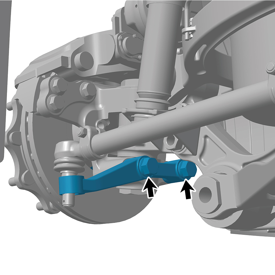
6
Remove the left steering arm.
Installation Procedures
1
Move the left steering arm to the mounting position.
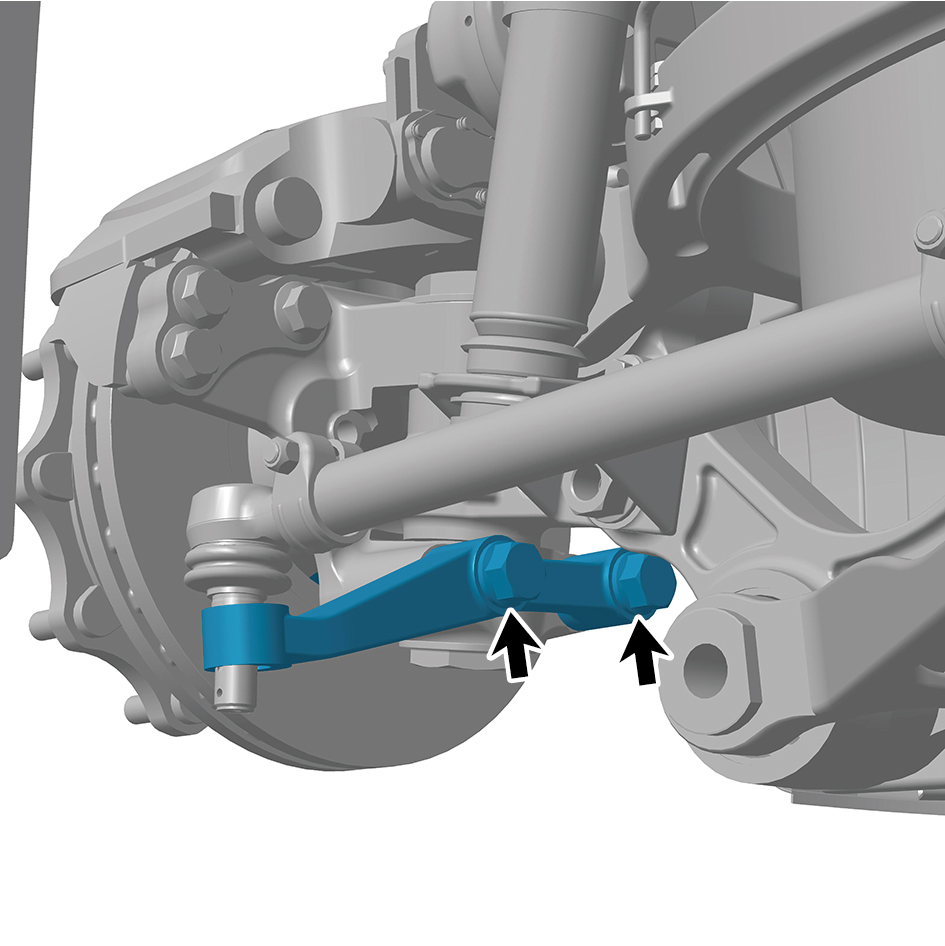
2
Install 2 fixing bolts of the left steering arm.
Torque:627 +/- 37 (ft lbs)
3
Install 1 fixing nut at the connection between the tie rod
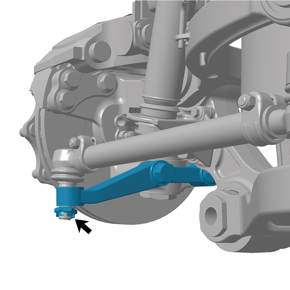
(left) and the left steering arm.
Torque:254.5 +/- 11 (ft lbs)
4
Install 1 cotter pin at the connection between the tie rod
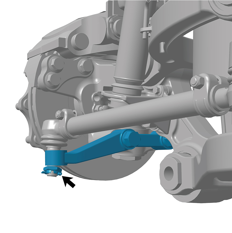
(left) and the left steering arm.
5
Install the guide wheel (left).
6
Lower the front end of the vehicle.
8.6.3.6 Replacement of Front Air Spring Assembly (left)
Assembly (left)
Removal Procedures
1
Release air pressure from the brake system.
2
Open the door.
3
Open the front flip cover plate.
4
Disconnect the battery negative cable.
caution
power down the high-voltage system before
disconnecting the negative pole of the storage
battery.
5
Jack the front end of the vehicle.
6
Remove the guide wheel (left).
7
Remove the front spring left upper mounting plate.
8
Remove the pressure sensor assembly.
9
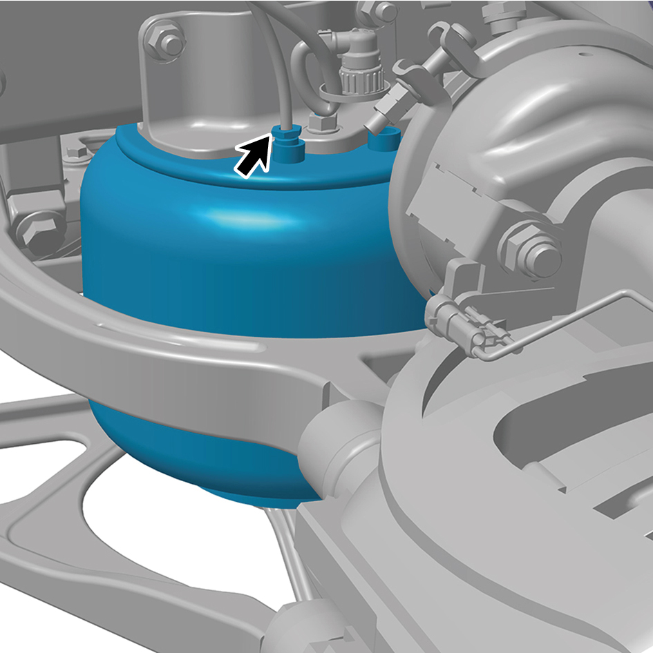
Disconnect 1 air pipe of the front air spring assembly (left).
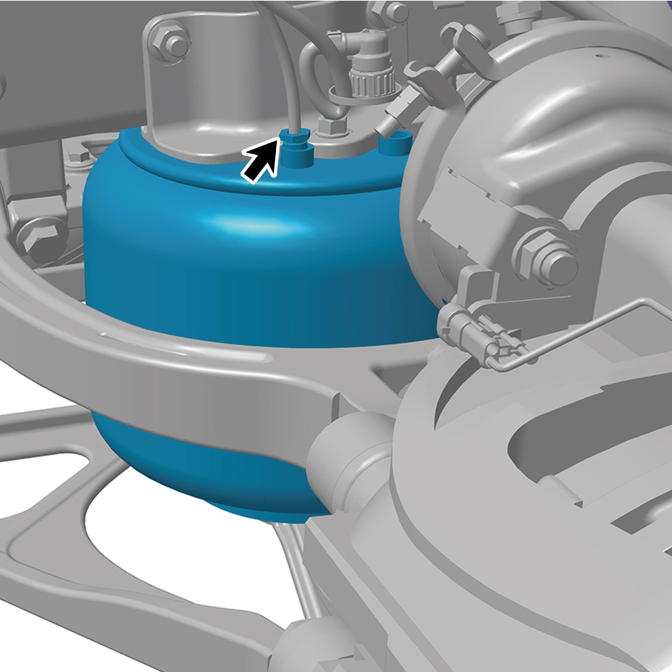
10
Remove 1 fixing nut at the upper part of the front air
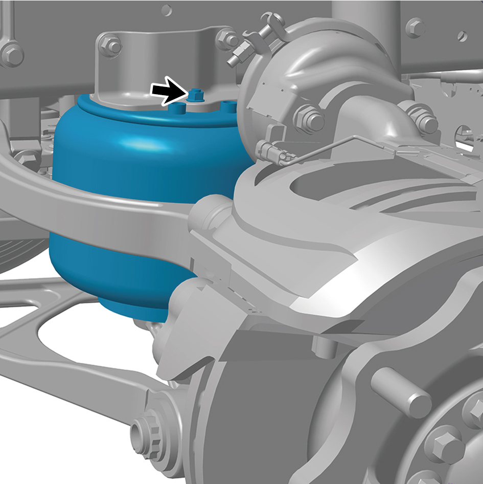
spring assembly (left).
11
Remove 1 fixing nut at the lower part of the front air spring
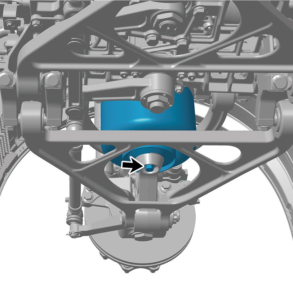
assembly (left).
12
Remove the front air spring assembly (left).
Installation Procedures
1
Move the front air spring assembly (left) to the mounting
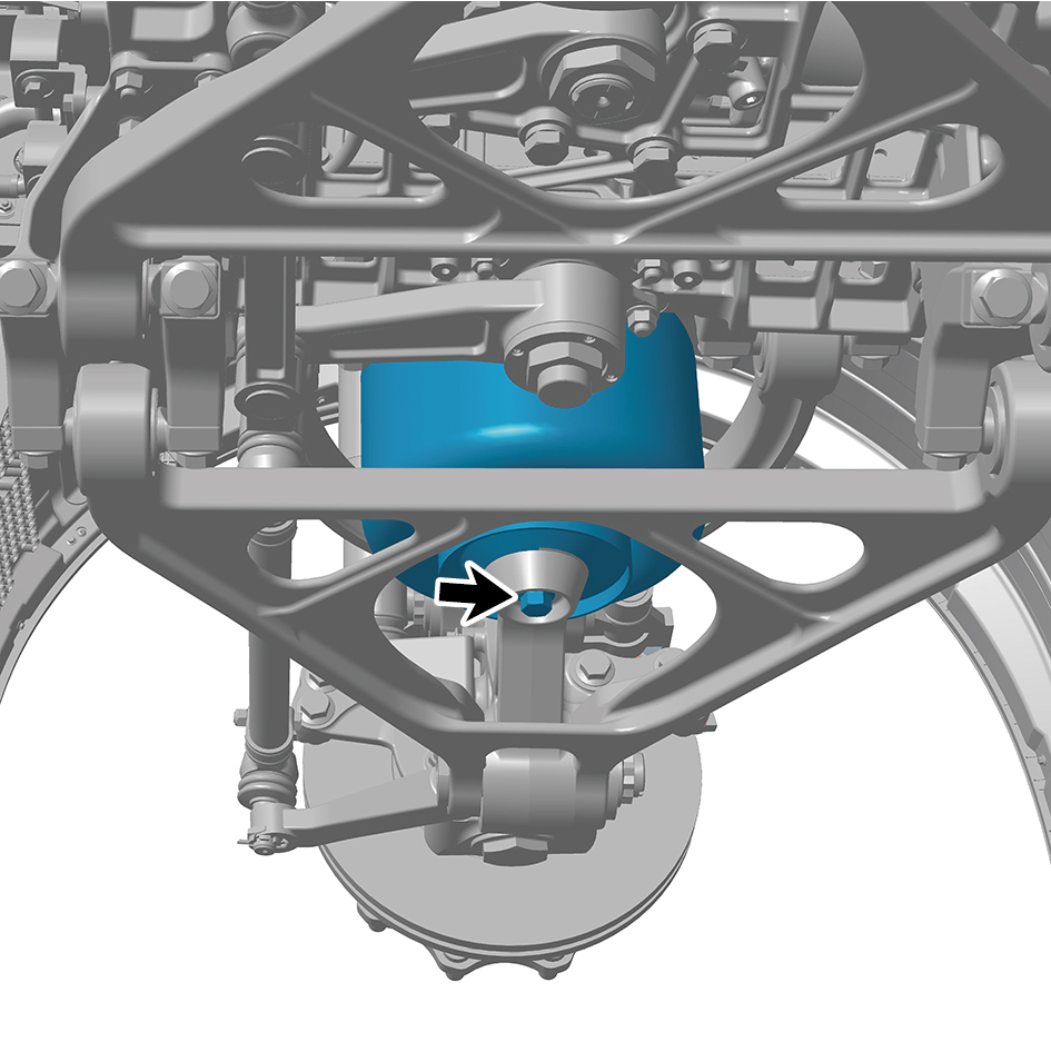
position.
2
Install 1 fixing nut at the lower part of the front air spring
assembly (left).
Torque: 199 +/- 18.5 (ft lbs)
3
Install 1 fixing nut at the upper part of the front air spring
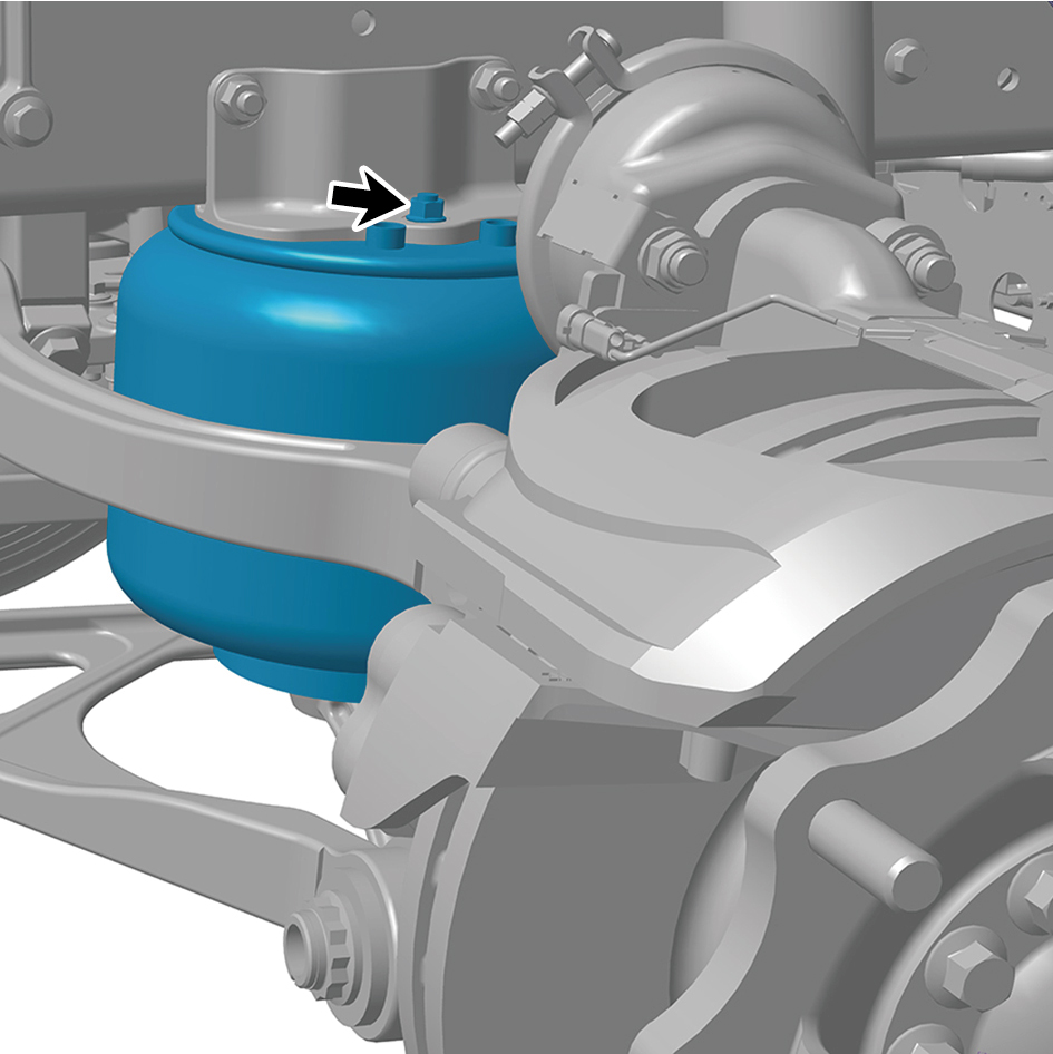
assembly (left).
Torque:40.5 +/- 3.5 (ft lbs)
4
Connect 1 air pipe of the front air spring assembly (left).
5
Install the pressure sensor assembly.
6
Install the front spring left upper mounting plate.
7
Install the guide wheel (left).
8
Lower the front end of the vehicle.
9
Connect the battery negative cable.
10
Close the front flip cover plate.
11
Close the door.
8.6.3.7 Replacement of Right Front Brake Assembly
Assembly
Removal Procedures
1
Release air pressure from the brake system.
2
Open the door.
3
Open the front flip cover plate.
4
Disconnect the battery negative cable.
caution
power down the high-voltage system before
disconnecting the negative pole of the storage
battery.
5
Jack the front end of the vehicle.
6
Remove the guide wheel (right).
7
Remove the brake chamber (right).
8
Disconnect 1 harness connector of the right front brake
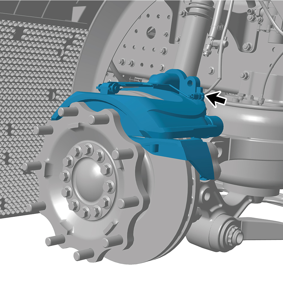
assembly.
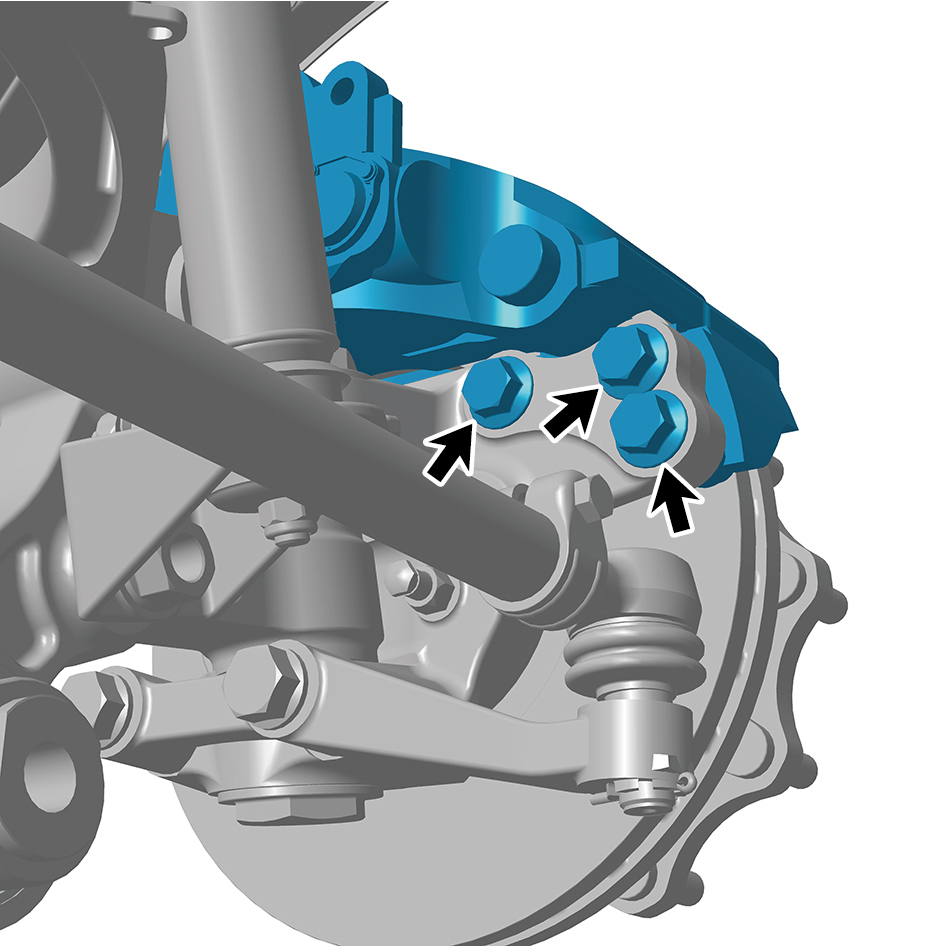
9
Remove 6 fixing bolts of the right front brake assembly,
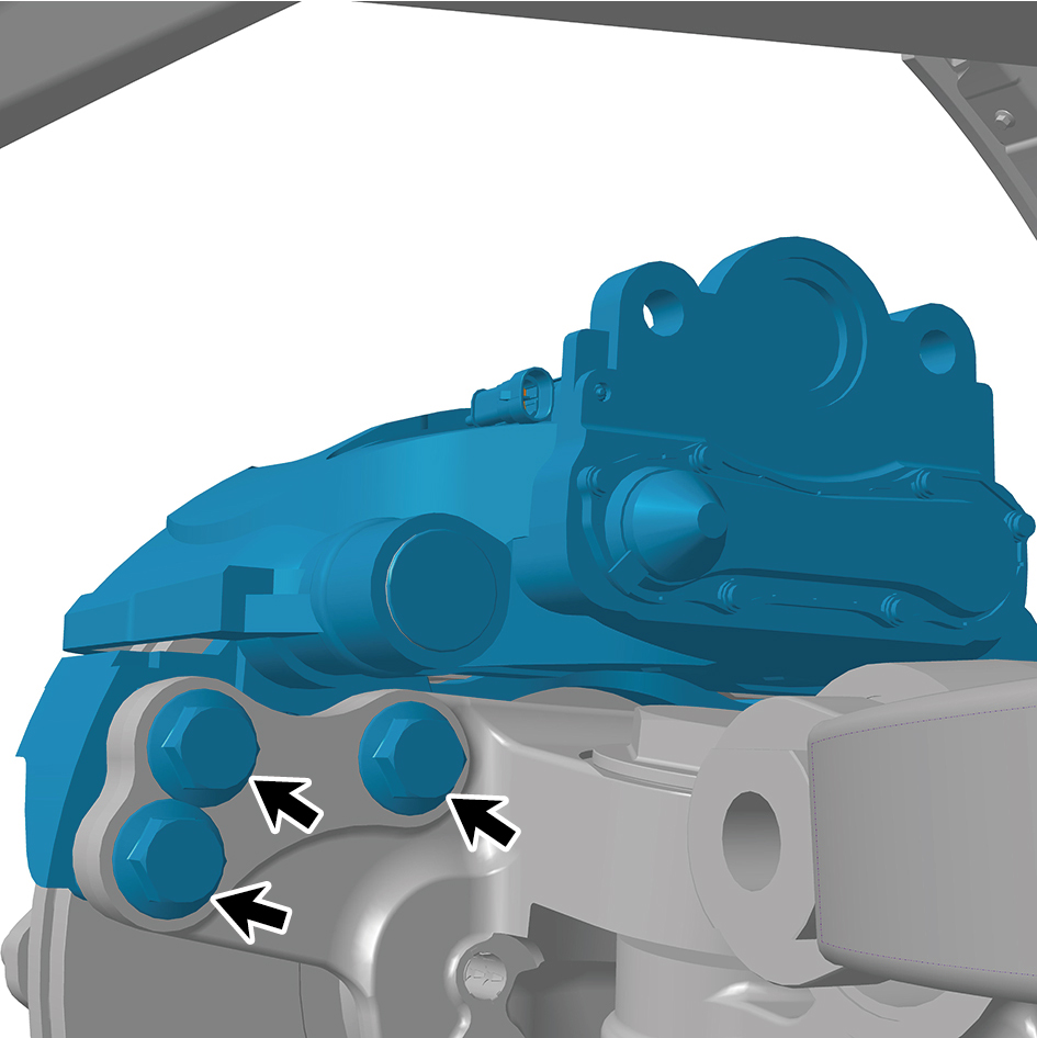
and remove the right front brake assembly.
Installation Procedures
1
Move the right front brake assembly to the mounting
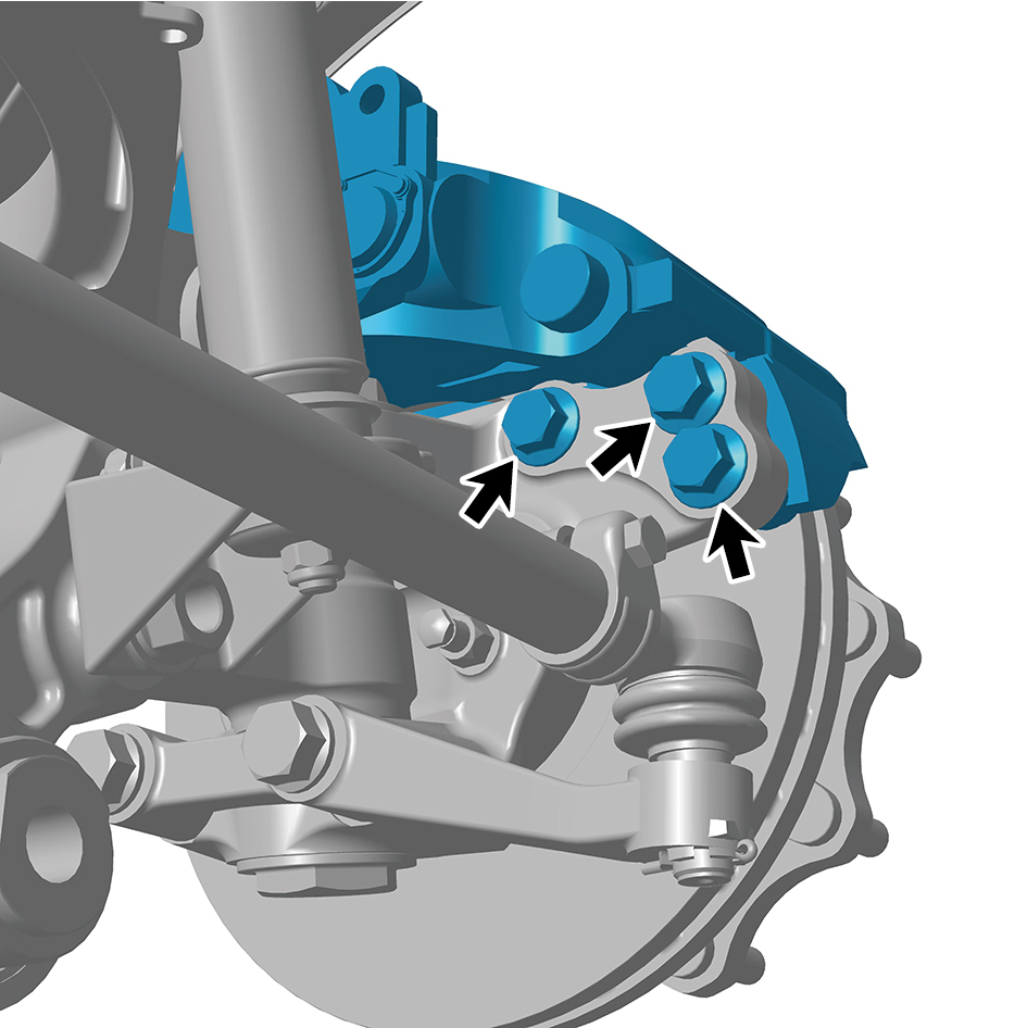
position.
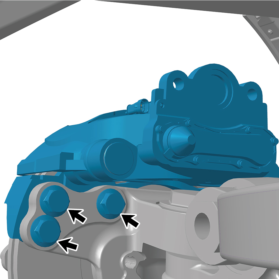
2
Install 6 fixing bolts of the right front brake assembly.
Torque:406 +/- 18.5 (ft lbs)
3
Connect 1 harness connector of the right front brake
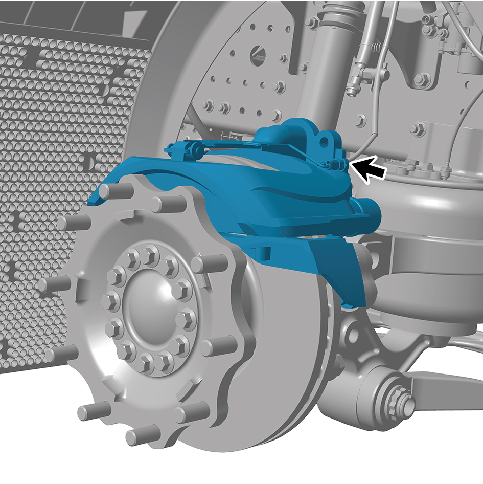
assembly.
caution
The harness is firmly connected following the
principal of "insert until a click is heard for
confirmation".
4
Install the brake chamber (right).
5
Install the guide wheel (right).
6
Lower the front end of the vehicle.
7
Connect the battery negative cable.
8
Close the front flip cover plate.
9
Close the door.
8.6.3.8 Replacement of Right Front Brake Body
Body
Removal Procedures
1
Release air pressure from the brake system.
2
Open the door.
3
Open the front flip cover plate.
4
Disconnect the battery negative cable.
caution
power down the high-voltage system before
disconnecting the negative pole of the storage
battery.
5
Jack the front end of the vehicle.
6
Remove the guide wheel (right).
7
Remove the brake chamber (right).
8
Remove the friction plate (right).
9
Disconnect 1 harness connector of the right front brake
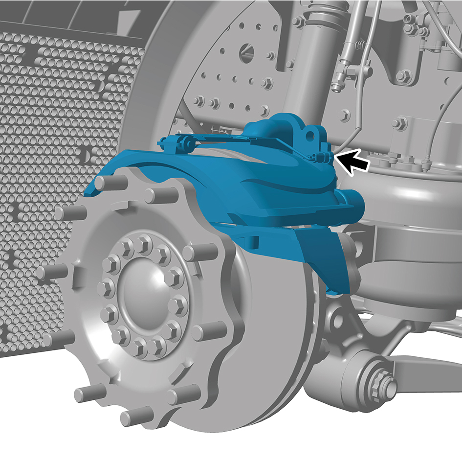
body.
10
Remove 6 fixing bolts of the right front brake body and
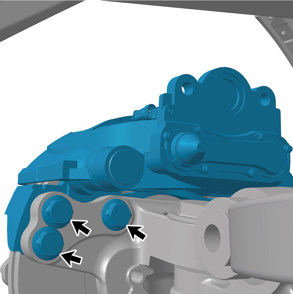
remove the right front brake body.
Installation Procedures
1
Move the right front brake body to the mounting position.
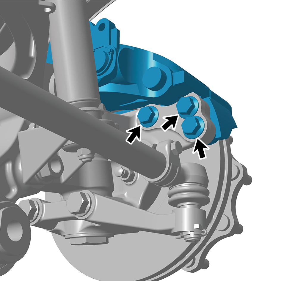
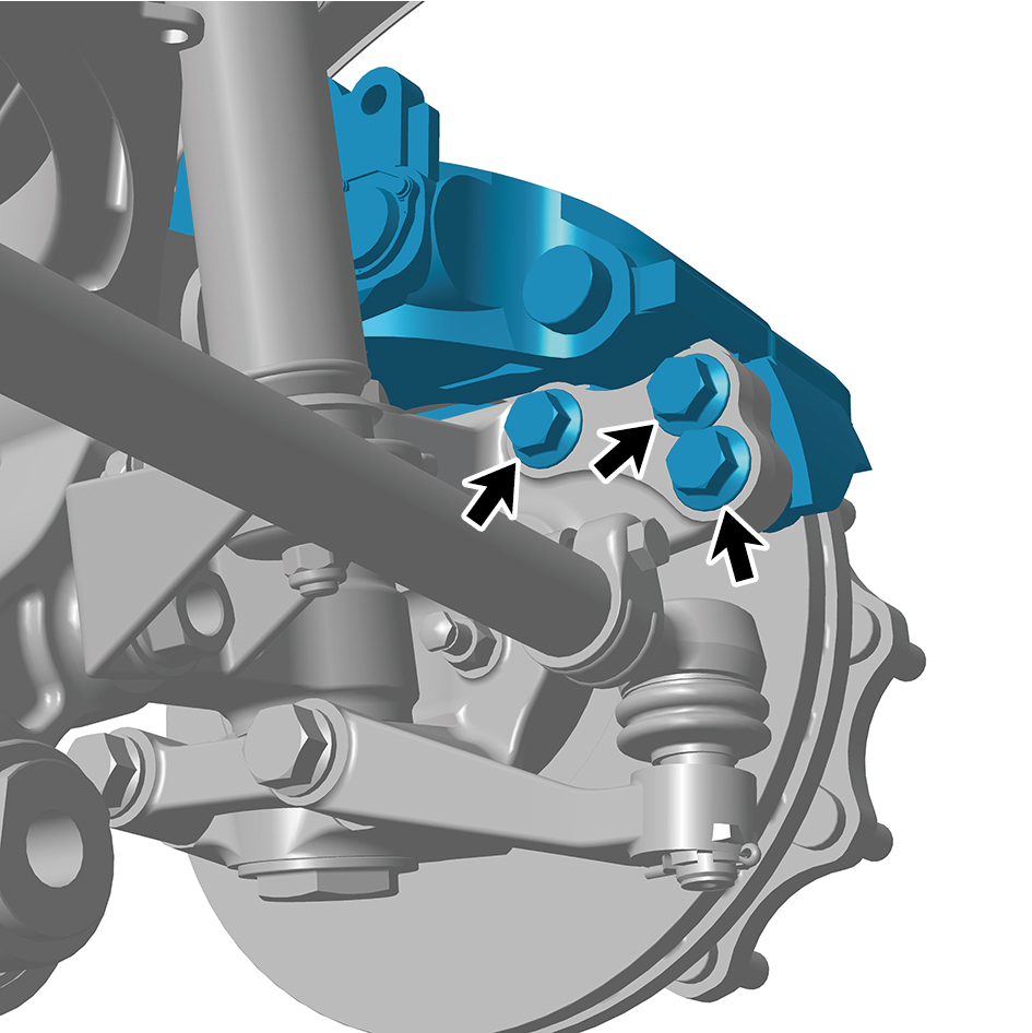
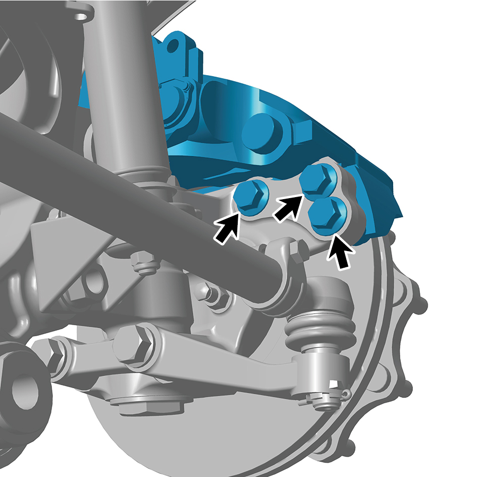
2
Install 6 fixing bolts of the right front brake body.
Torque: 405.5 +/- 18.5 (ft lbs)
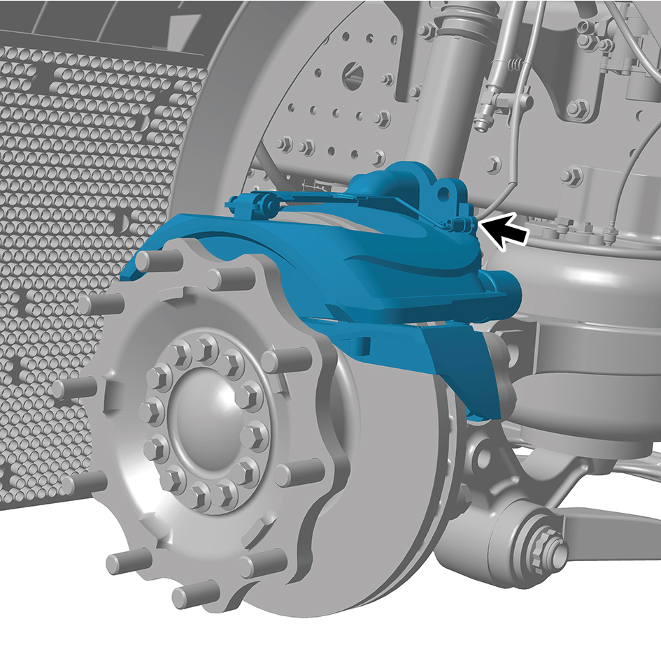
3
Connect 1 harness connector of the right front brake body.
caution
The harness is firmly connected following the
principal of "insert until a click is heard for
confirmation".
4
Install the friction plate (right).
5
Install the brake chamber (right).
6
Install the guide wheel (right).
7
Lower the front end of the vehicle.
8
Connect the battery negative cable.
9
Close the front flip cover plate.
10
Close the door.
8.6.3.9 Replacement of Right Upper Swing Arm Assembly
Arm Assembly
Removal Procedures
1
Release air pressure from the brake system.
2
Open the door.
3
Open the front flip cover plate.
4
Disconnect the battery negative cable.
caution
power down the high-voltage system before
disconnecting the negative pole of the storage
battery.
5
Jack the front end of the vehicle.
6
Remove the guide wheel (right).
7
Remove the front spring right upper mounting plate.
8
Remove the front air spring assembly (right).
9
Remove the brake chamber (right).
10
Remove the front shock absorber assembly (right).
11
Remove the right front wheel end assembly.
12
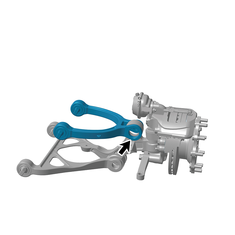
Remove the swing arm outside pivot (right).
13
Remove the right upper swing arm assembly.
Installation Procedures
1
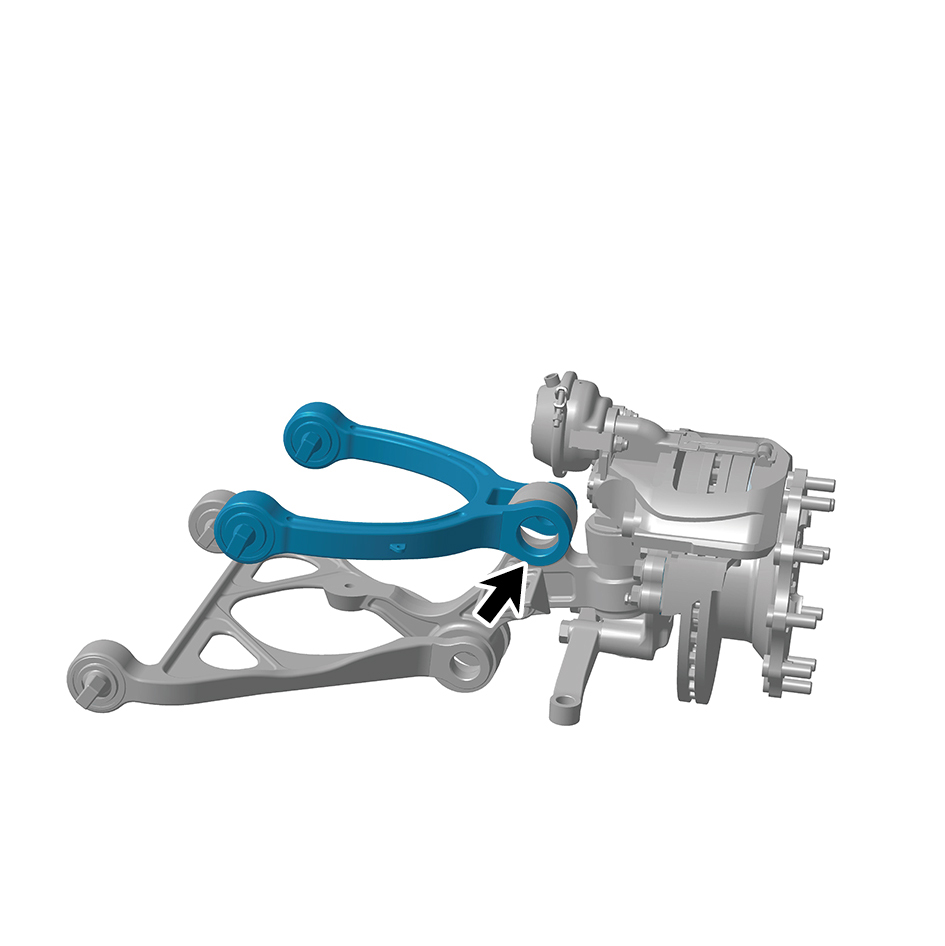
Install the right upper swing arm assembly.
2
Install the swing arm outside pivot (right).
3
Install the right front wheel end assembly.
4
Install the front shock absorber assembly (right).
5
Install the brake chamber (right).
6
Install the front air spring assembly (right).
7
Install the front spring right upper mounting plate.
8
Install the guide wheel (right).
9
Lower the front end of the vehicle.
10
Connect the battery negative cable.
11
Close the front flip cover plate.
12
Close the door.
caution
After part replacement, it is necessary to perform
four-wheel alignment.
8.6.3.10 Replacement of Right Lower Swing Arm Assembly
Arm Assembly
Removal Procedures
1
Release air pressure from the brake system.
2
Open the door.
3
Open the front flip cover plate.
4
Disconnect the battery negative cable.
caution
power down the high-voltage system before
disconnecting the negative pole of the storage
battery.
5
Jack the front end of the vehicle.
6
Remove the guide wheel (right).
7
Remove the front spring right upper mounting plate.
8
Remove the front air spring assembly (right).
9
Remove the brake chamber (right).
10
Remove the front shock absorber assembly (right).
11
Remove the right front wheel end assembly.
12
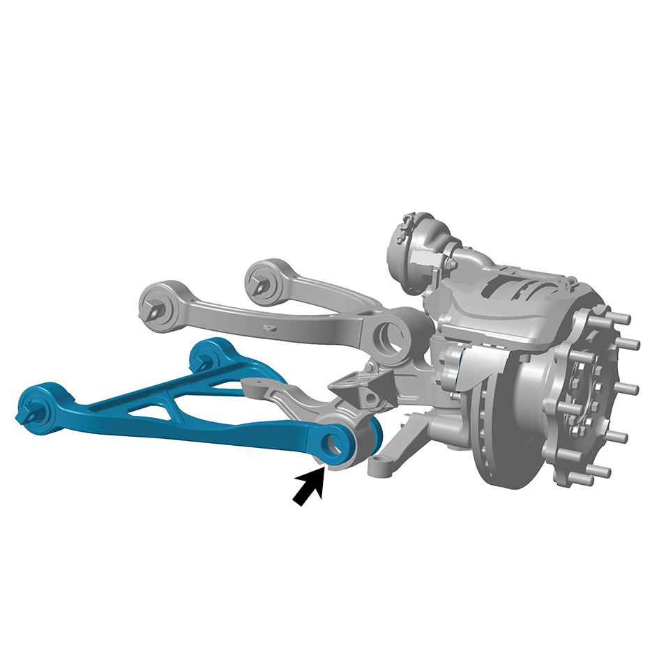
Remove the swing arm outside pivot (right).
13
Remove the right lower swing arm assembly.
Installation Procedures
1
Install the right lower swing arm assembly.
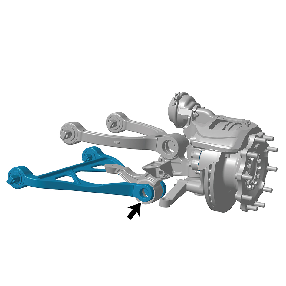
2
Install the swing arm outside pivot (right).
3
Install the right front wheel end assembly.
4
Install the front shock absorber assembly (right).
5
Install the brake chamber (right).
6
Install the front air spring assembly (right).
7
Install the front spring right upper mounting plate.
8
Install the guide wheel (right).
9
Lower the front end of the vehicle.
10
Connect the battery negative cable.
11
Close the front flip cover plate.
12
Close the door.
8.6.3.11 Replacement of Right Steering Arm
Removal Procedures
1
Jack the front end of the vehicle.
2
Remove the guide wheel (right).
3
Remove 1 cotter pin at the connection between the tie rod
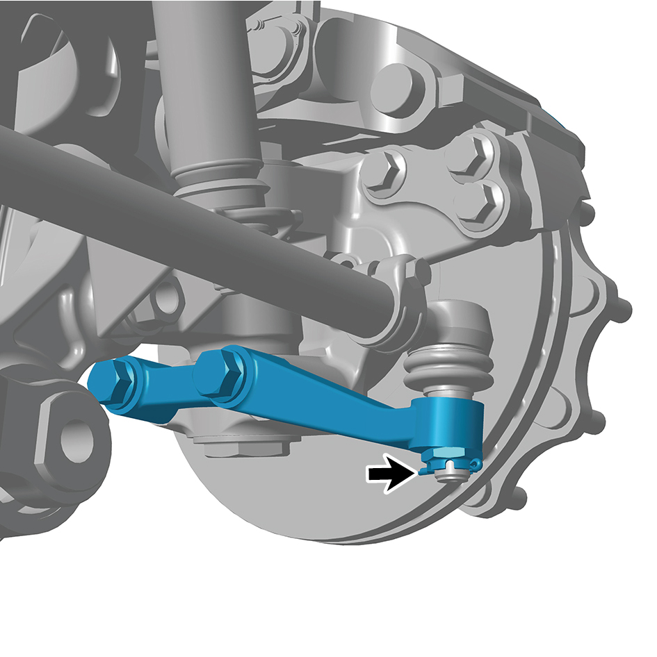
(right) and the right steering arm.
4
Remove 1 fixing nut at the connection between the tie rod
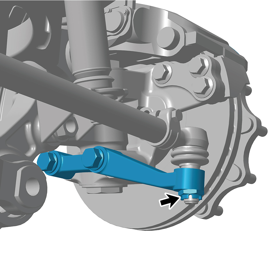
(right) and the right steering arm to separate the tie rod
(right).
5
Remove 2 fixing bolts of the right steering arm.
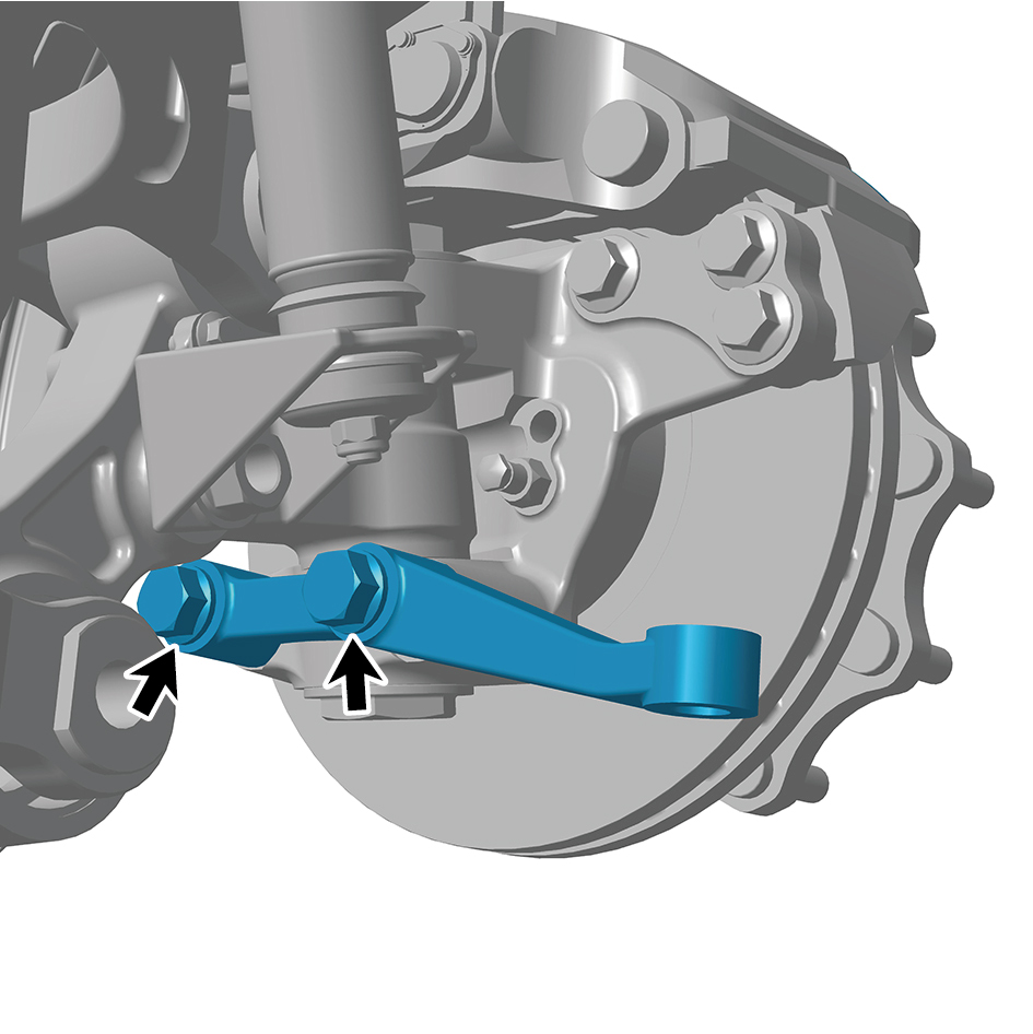
6
Remove the right steering arm.
Installation Procedures
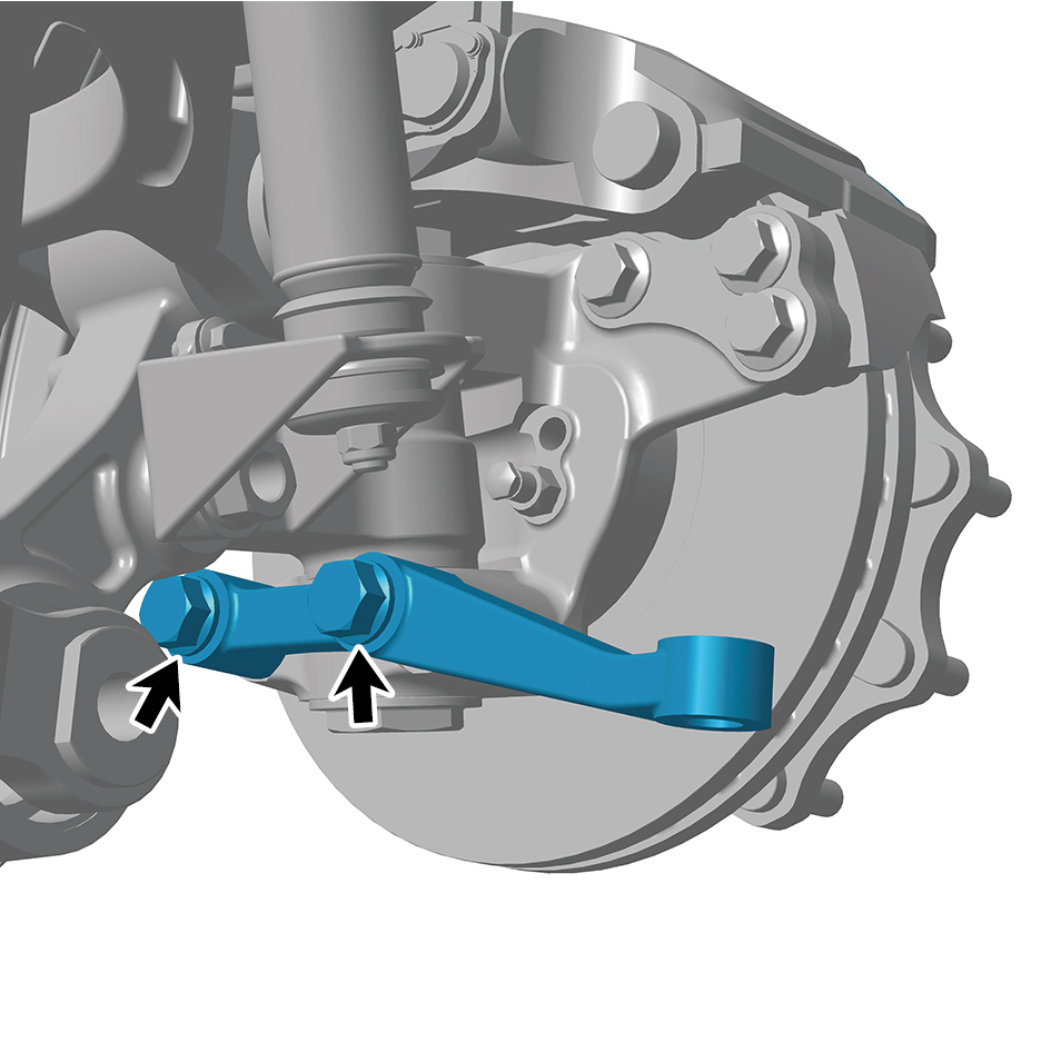
1
Move the right steering arm to the mounting position.
2
Install 2 fixing bolts of the right steering arm.
Torque:627 +/- 37 (ft lbs)
3
Install 1 fixing nut at the connection between the tie rod
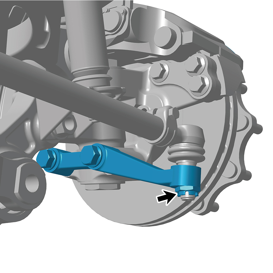
(right) and the right steering arm.
Torque: 255 +/- 11 (ft lbs)
4
Install 1 cotter pin at the connection between the tie rod
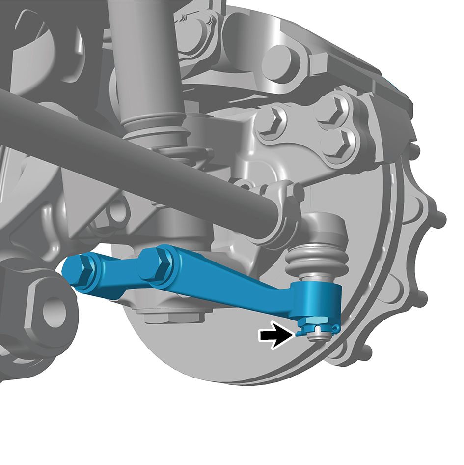
(right) and the right steering arm.
5
Install the guide wheel (right).
6
Lower the front end of the vehicle.
8.6.3.12 Replacement of Front Air Spring Assembly (right)
Assembly (right)
Removal Procedures
1
Release air pressure from the brake system.
2
Open the door.
3
Open the front flip cover plate.
4
Disconnect the battery negative cable.
caution
power down the high-voltage system before
disconnecting the negative pole of the storage
battery.
5
Jack the front end of the vehicle.
6
Remove the guide wheel (right).
7
Remove the front spring left upper mounting plate.
8
Remove the pressure sensor assembly.
9
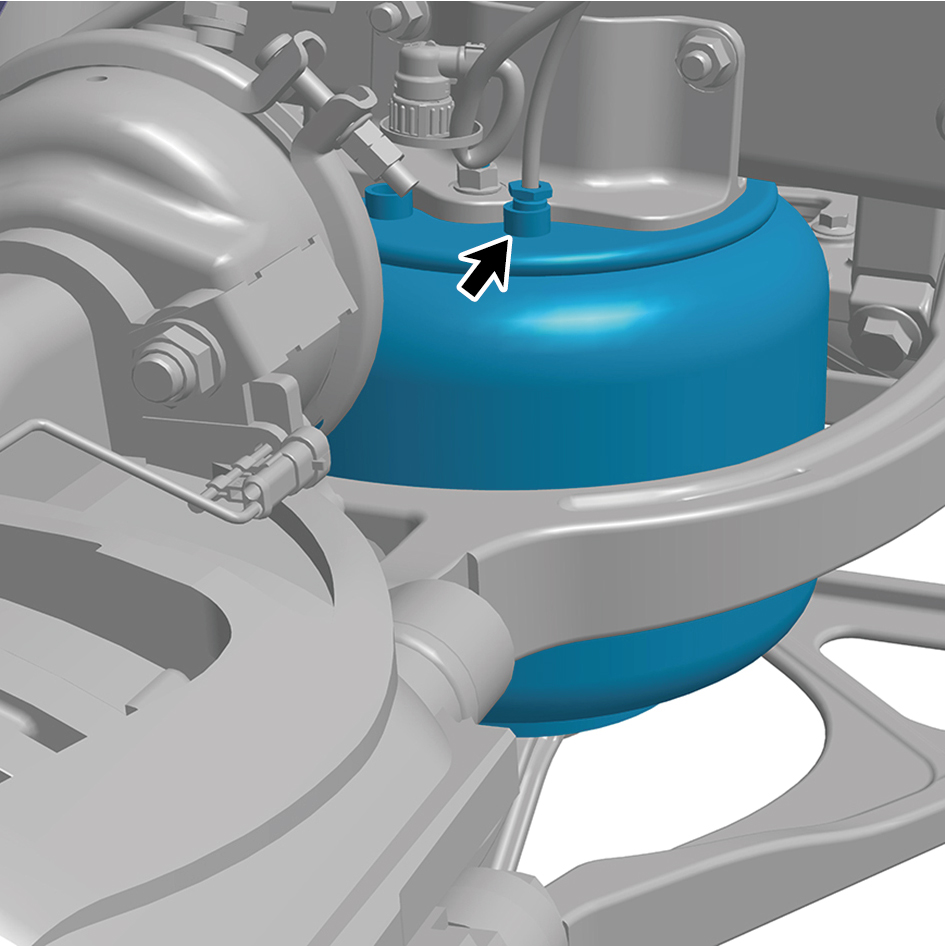
Disconnect 1 air pipe of the front air spring assembly
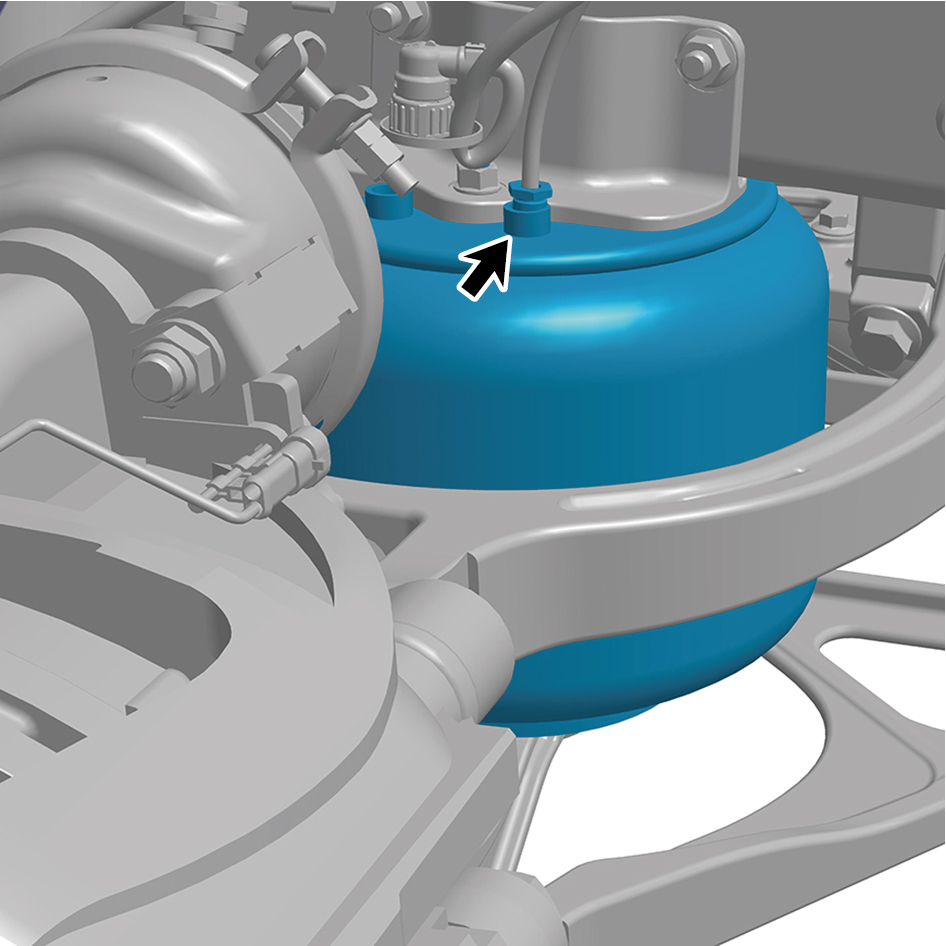
(right).
10
Remove 1 fixing nut at the upper part of the front air
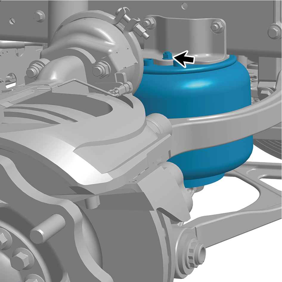
spring assembly (right).
11
Remove 1 fixing nut at the lower part of the front air spring
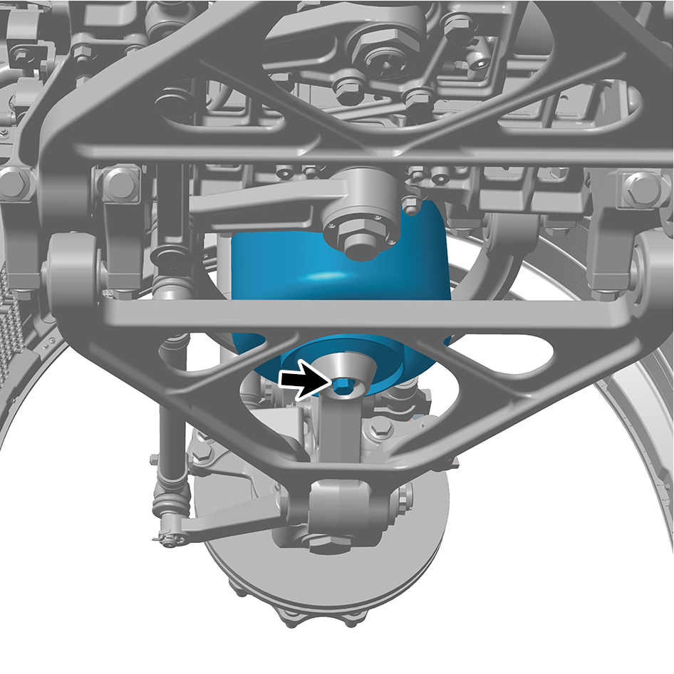
assembly (right).
12
Remove the front air spring assembly (right).
Installation Procedures
1
Move the front air spring assembly (right) to the mounting
position.
2
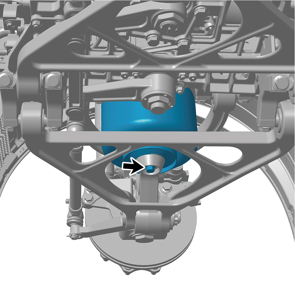
Install 1 fixing nut at the lower part of the front air spring
assembly (right).
Torque: 199 +/- 18.5 (ft lbs)
3
Install 1 fixing nut at the upper part of the front air spring
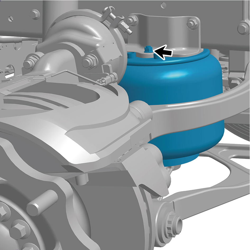
assembly (right).
Torque:40.5 +/- 3.5 (ft lbs)
4
Connect 1 air pipe of the front air spring assembly (right).
5
Install the pressure sensor assembly.
6
Install the front spring left upper mounting plate.
7
Install the guide wheel (right).
8
Lower the front end of the vehicle.
9
Connect the battery negative cable.
10
Close the front flip cover plate.
11
Close the door.
8.6.3.13 Replacement of Brake Disc
Removal Procedures
1
Release air pressure from the brake system.
2
Open the door.
3
Open the front flip cover plate.
4
Disconnect the battery negative cable.
caution
power down the high-voltage system before
disconnecting the negative pole of the storage
battery.
5
Jack the front end of the vehicle.
6
Remove the guide wheel (right).
7
Remove the brake chamber (right).
8
Remove the right front brake assembly.
9
Remove the hub flange assembly (right) .
10
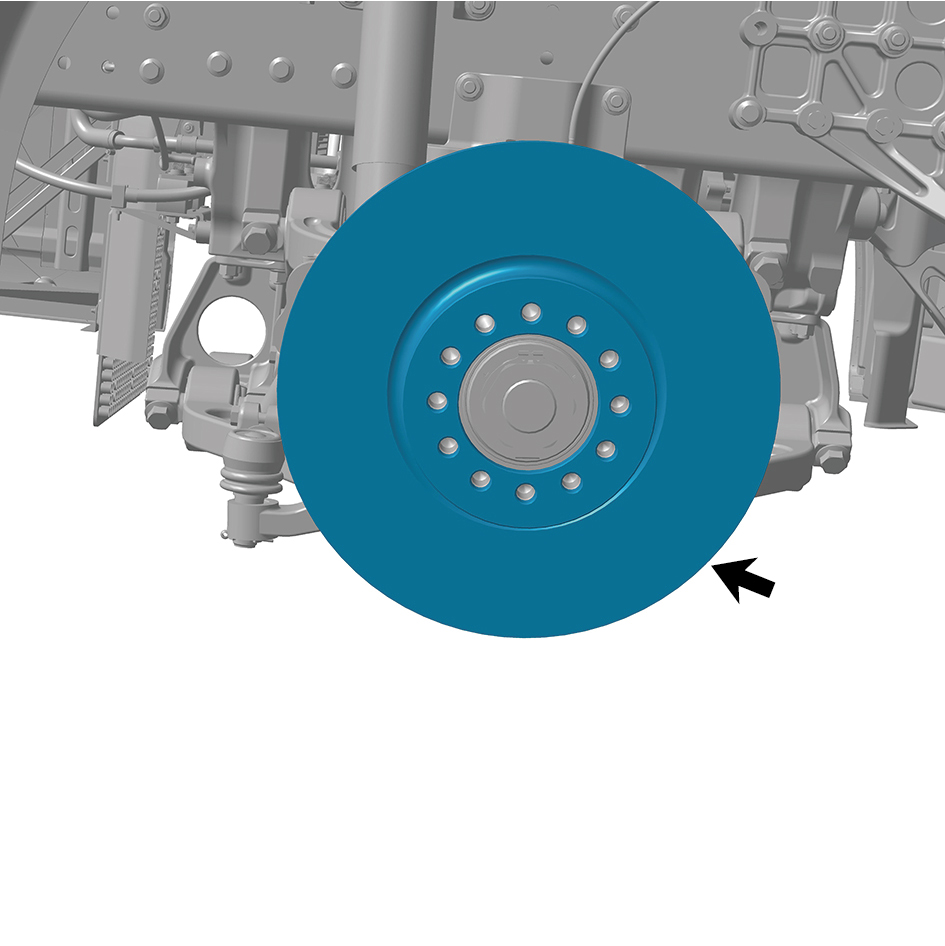
Remove the brake disc (right).
caution
Due to the heavy weight of the brake disc (right), it
shall be removed with the help of an assistant.
Installation Procedures
1
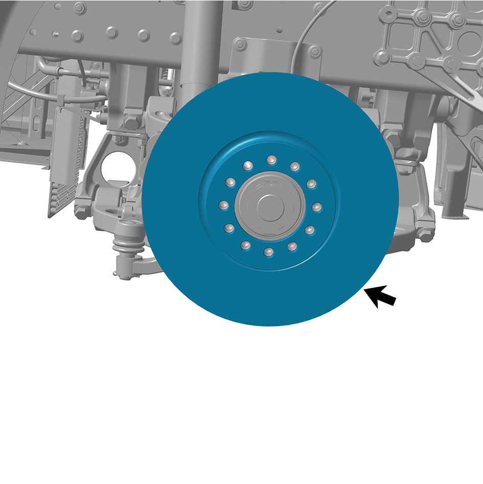
Install the brake disc (right).
caution
Due to the heavy weight of brake disc (right), it shall
be moved to the mounting position with the help of
an assistant.
2
Install the hub flange assembly (right).
3
Install the right front brake assembly.
4
Install the brake chamber (right).
5
Install the guide wheel (right).
6
Lower the front end of the vehicle.
7
Connect the battery negative cable.
8
Close the front flip cover plate.
9
Close the door.
8.6.3.14 Replacement of Brake Disc
Removal Procedures
1
Release air pressure from the brake system.
2
Open the door.
3
Open the front flip cover plate.
4
Disconnect the battery negative cable.
caution
power down the high-voltage system before
disconnecting the negative pole of the storage
battery.
5
Jack the front end of the vehicle.
6
Remove the guide wheel (left).
7
Remove the brake chamber (left).
8
Remove the left front brake assembly.
9
Remove the hub flange assembly (left).
10
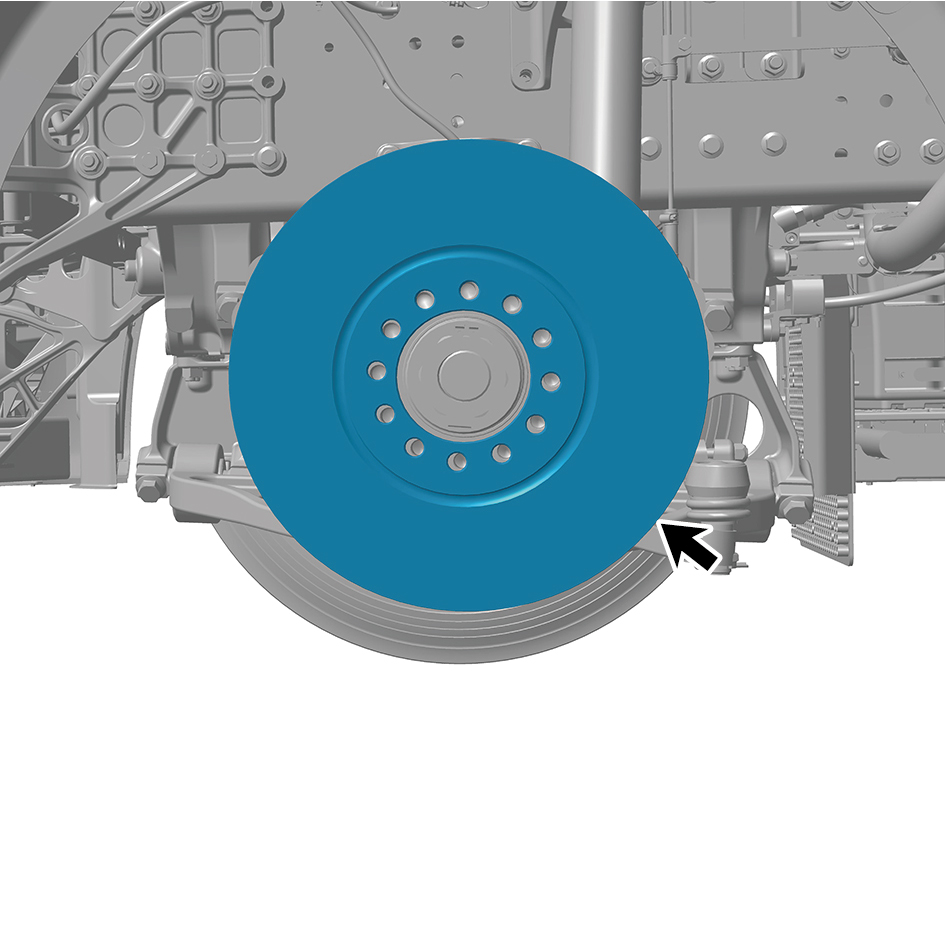
Remove the brake disc (left).
caution
Due to the heavy weight of the brake disc (left), it
shall be removed with the help of an assistant.
Installation Procedures
1
Install the brake disc (left).
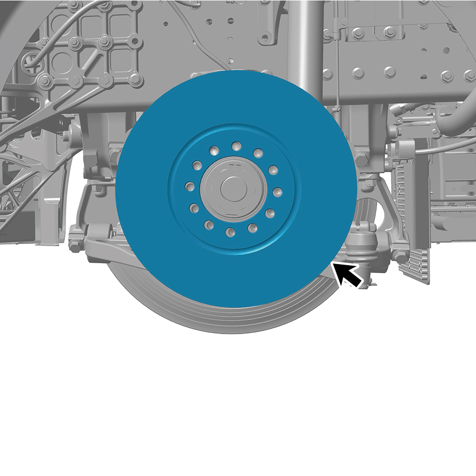
caution
Due to the heavy weight of brake disc (left), it shall
be moved to the mounting position with the help of
an assistant.
2
Install the hub flange assembly (left).
3
Install the left front brake assembly.
4
Install the brake chamber (left).
5
Install the guide wheel (left).
6
Lower the front end of the vehicle.
7
Connect the battery negative cable.
8
Close the front flip cover plate.
9
Close the door.
8.6.3.15 Replacement of Friction Plate
Removal Procedures
1
Jack the front end of the vehicle.
2
Remove the guide wheel (left).
3
Remove 1 fixing pin of the friction plate (left) cover plate,
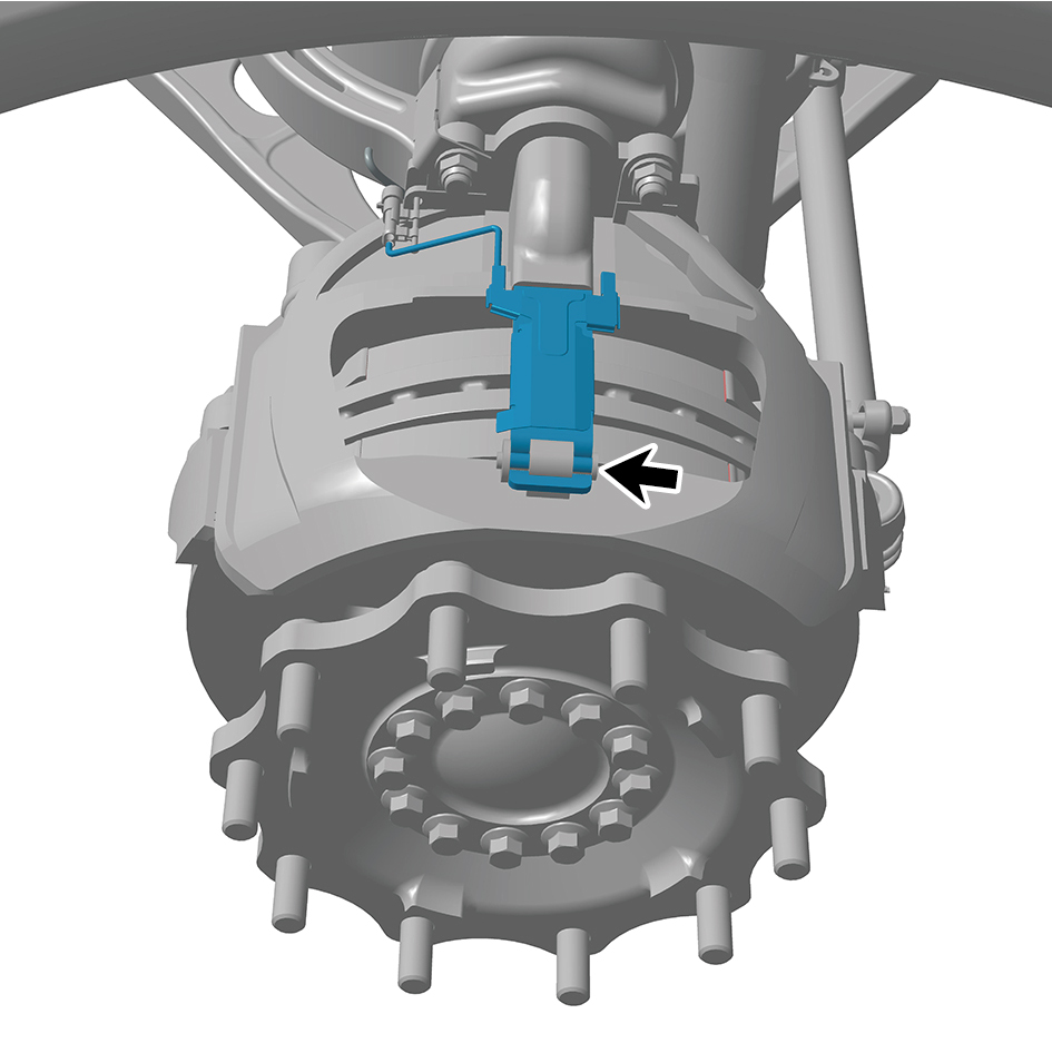
and open the friction plate (left) cover plate.
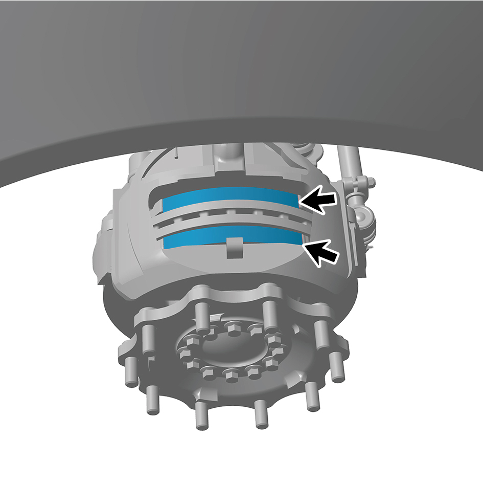
4
Remove the friction plate (left).
Installation Procedures
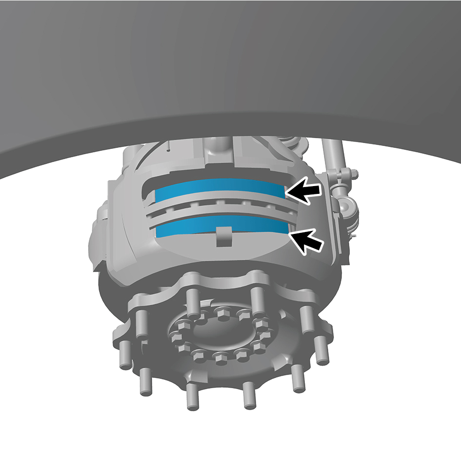
1
Install the friction plate (left).
2
Close the friction plate (left) cover plate, and install 1 fixing
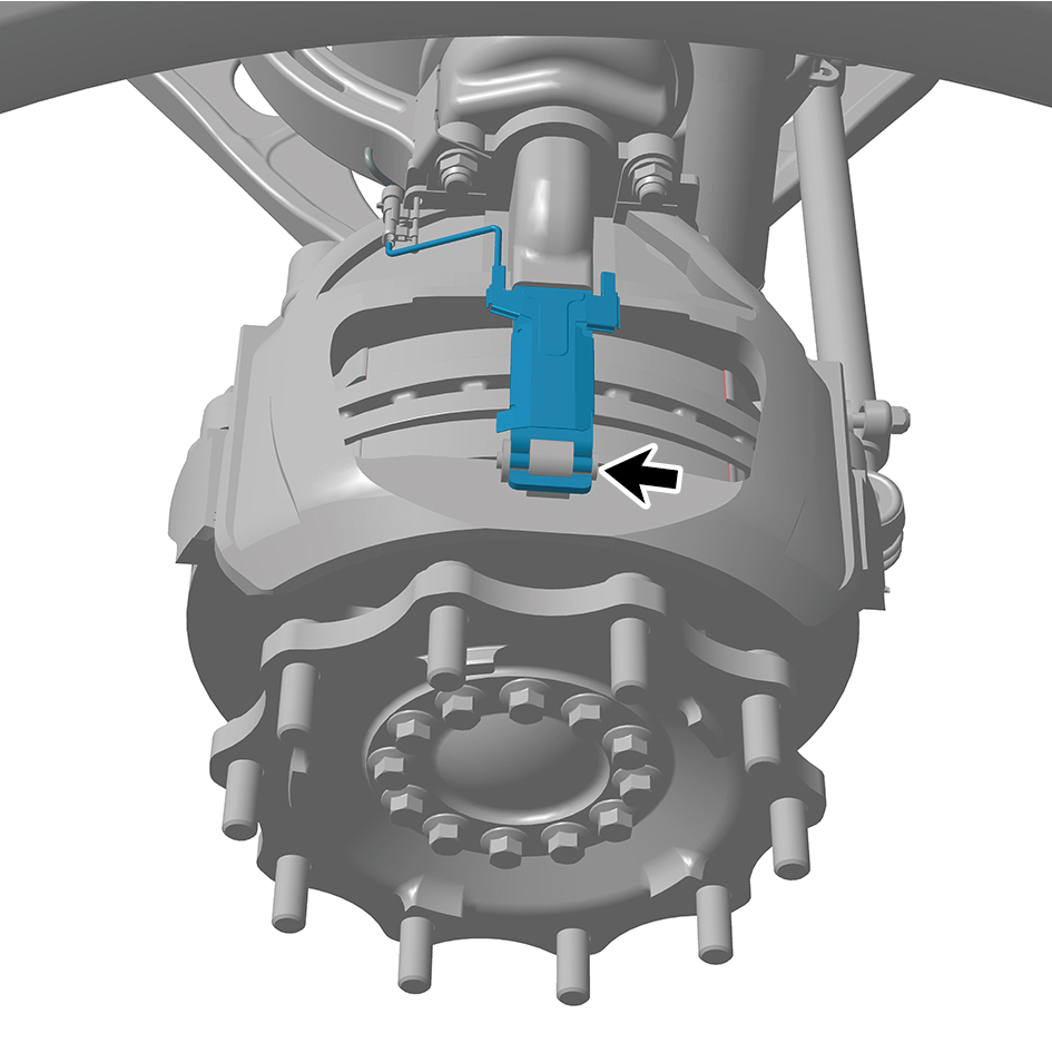
pin of the friction plate (left) cover plate.
3
Install the guide wheel (left).
4
Lower the front end of the vehicle.
8.6.3.16 Replacement of Friction Plate
Removal Procedures
1
Jack the front end of the vehicle.
2
Remove the guide wheel (right).
3
Remove 1 fixing pin of the friction plate (right) cover plate,
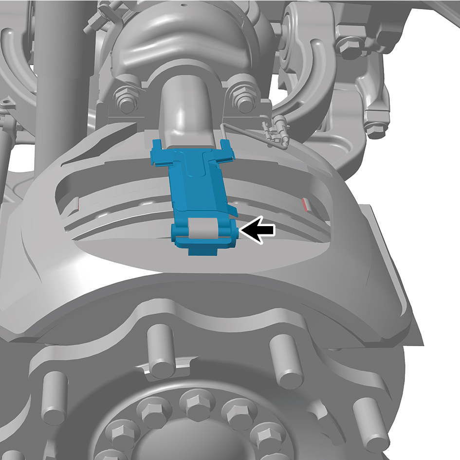
and open the friction plate (right) cover plate.
4
Remove the friction plate (right).
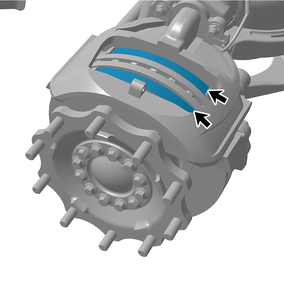
Installation Procedures
1
Install the friction plate (right).
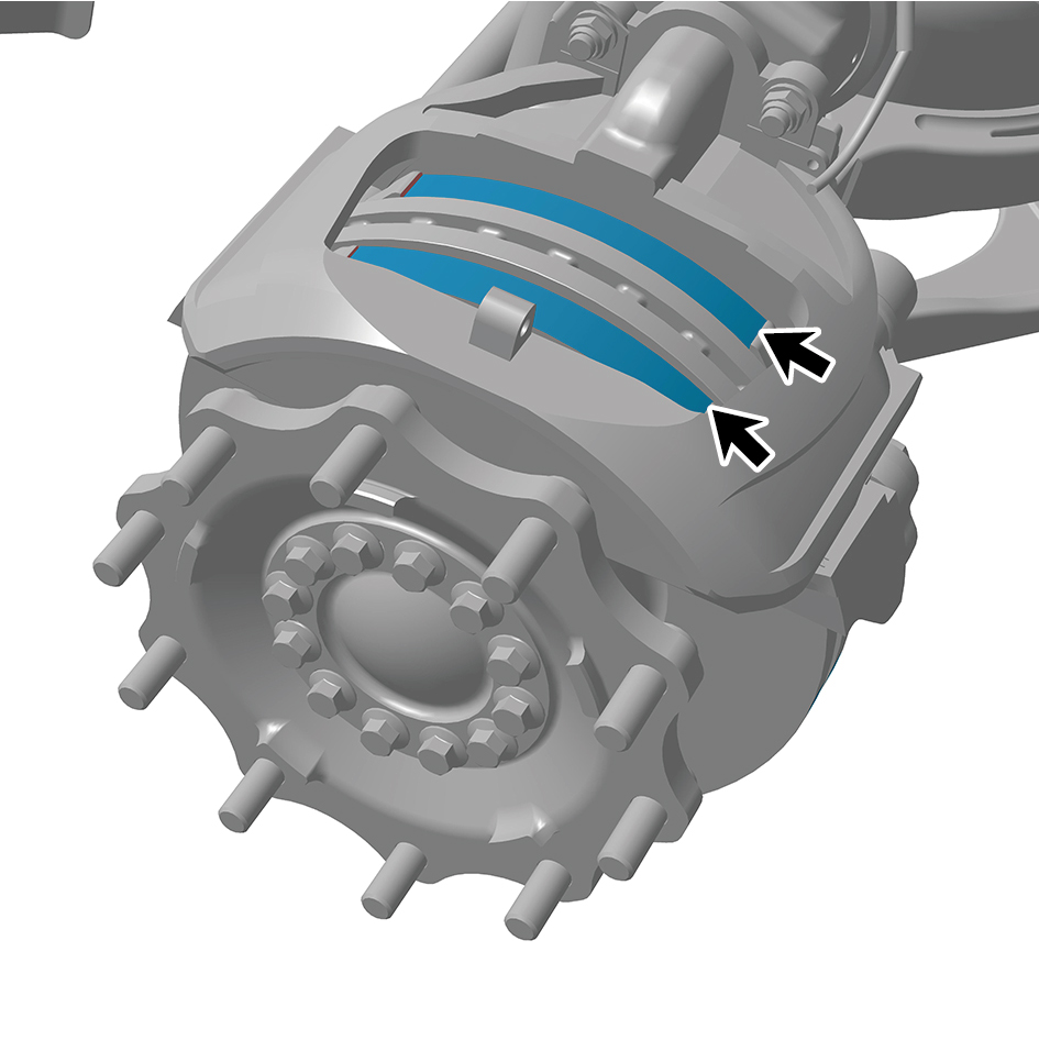
2
Close the friction plate (right) cover plate, and install 1
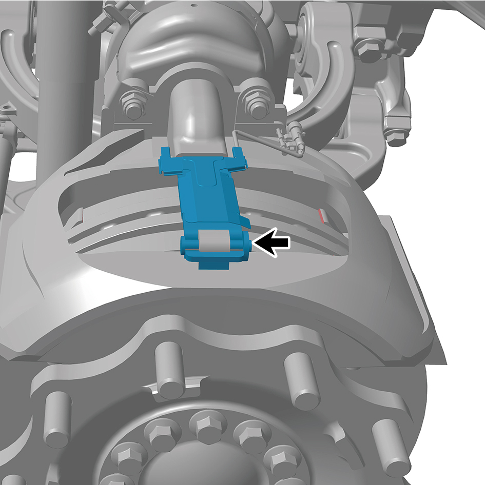
fixing pin of the friction plate (right) cover plate.
3
Install the guide wheel (right).
4
Lower the front end of the vehicle.
8.6.3.17 Replacement of Hub Bearing Unit
Removal Procedures
1
Release air pressure from the brake system.
2
Open the door.
3
Open the front flip cover plate.
4
Disconnect the battery negative cable.
caution
power down the high-voltage system before
disconnecting the negative pole of the storage
battery.
5
Jack the front end of the vehicle.
6
Remove the guide wheel (left).
7
Remove the brake chamber (left).
8
Remove the left front brake assembly.
9
Remove the hub flange assembly (left) .
10
Remove the brake disc (left).
11
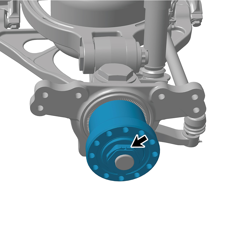
Remove the circlip.
12
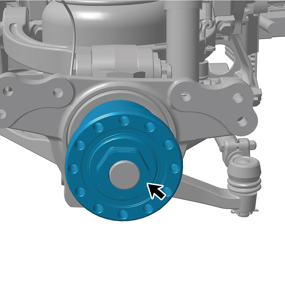
Remove 1 lock nut of the hub bearing unit (left).
13
Remove the hub bearing unit (left).
Installation Procedures
1
Move the hub bearing unit (left) to the mounting position.
2
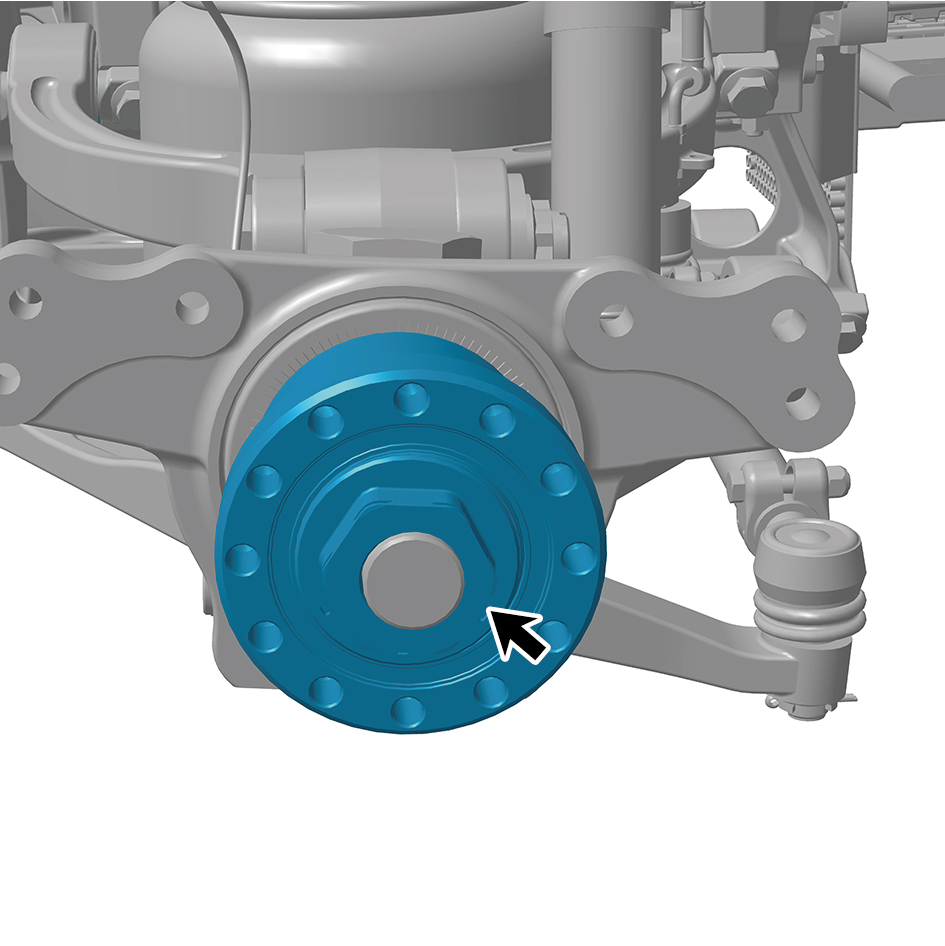
Install 1 lock nut of the hub bearing unit (left).
Torque:442.5 +/- 37 (ft lbs)
3
Install the circlip.
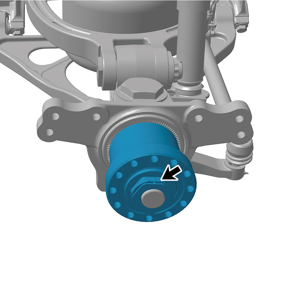
4
Install the brake disc (left).
5
Install the hub flange assembly (left) .
6
Install the left front brake assembly.
7
Install the brake chamber (left).
8
Install the guide wheel (left).
9
Lower the front end of the vehicle.
10
Connect the battery negative cable.
11
Close the front flip cover plate.
12
Close the door.
8.6.3.18 Replacement of Hub Bearing Unit
Removal Procedures
1
Release air pressure from the brake system.
2
Open the door.
3
Open the front flip cover plate.
4
Disconnect the battery negative cable.
caution
power down the high-voltage system before
disconnecting the negative pole of the storage
battery.
5
Jack the front end of the vehicle.
6
Remove the guide wheel (right).
7
Remove the brake chamber (right).
8
Remove the right front brake assembly.
9
Remove the hub flange assembly (right).
10
Remove the brake disc (right).
11
Remove the circlip.
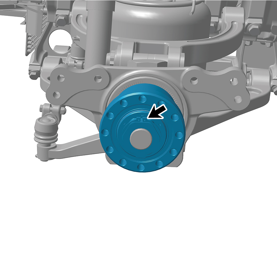
12
Remove 1 lock nut of the hub bearing unit (right).
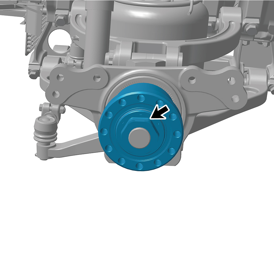
13
Remove the hub bearing unit (right).
Installation Procedures
1
Move the hub bearing unit (right) to the mounting position.
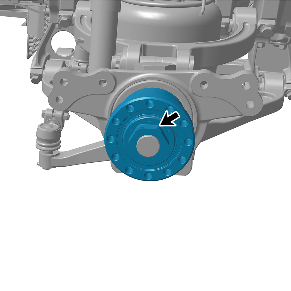
2
Install 1 lock nut of the hub bearing unit (right).
Torque: 442.5 +/- 37 (ft lbs)
3
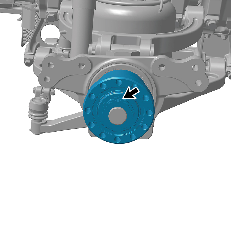
Install the circlip.
4
Install the brake disc (right).
5
Install the hub flange assembly (right).
6
Install the right front brake assembly.
7
Install the brake chamber (right).
8
Install the guide wheel (right).
9
Lower the front end of the vehicle.
10
Connect the battery negative cable.
11
Close the front flip cover plate.
12
Close the door.
8.6.3.19 Replacement of Light Steering Knuckle with Kingpin Assembly
Knuckle with Kingpin Assembly
Removal Procedures
1
Release air pressure from the brake system.
2
Open the door.
3
Open the front flip cover plate.
4
Disconnect the battery negative cable.
caution
power down the high-voltage system before
disconnecting the negative pole of the storage
battery.
5
Jack the front end of the vehicle.
6
Remove the guide wheel (left).
7
Remove the brake chamber (left).
8
Remove the left front brake assembly.
9
Remove the hub flange assembly (left).
10
Remove the brake disc (left).
11
Remove the hub bearing unit (left).
12
Remove the left steering arm.
13
Remove the ABS sensor.
14
Remove the Front shock absorber lower mounting
bracket.
15
Remove the swing arm outside pivot (left).
16
Use a tool to support the left steering knuckle with kingpin
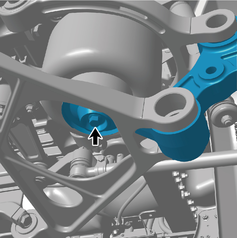
assembly.
17
Remove 1 fixing bolt of the left steering knuckle with
kingpin assembly.
18
Remove the left steering knuckle with kingpin assembly.
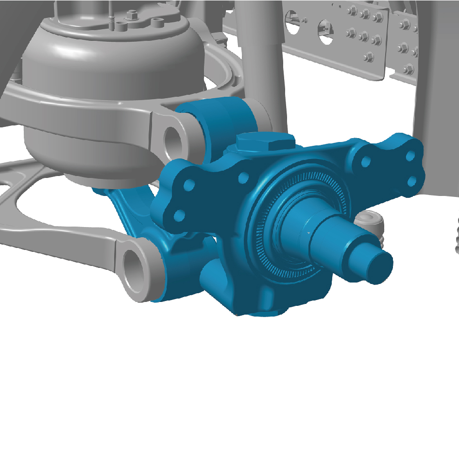
Installation Procedures
1
Move the right steering knuckle with kingpin assembly to
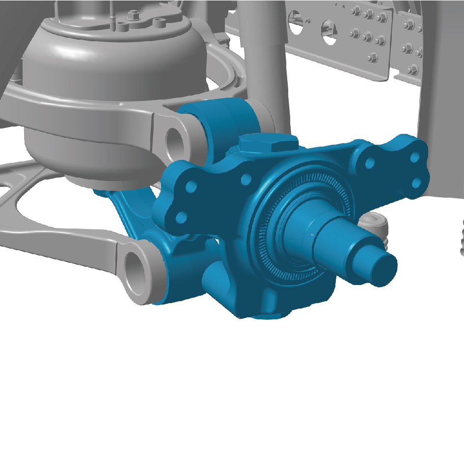
the mounting position.
2
Install 1 fixing bolt of the right steering knuckle with
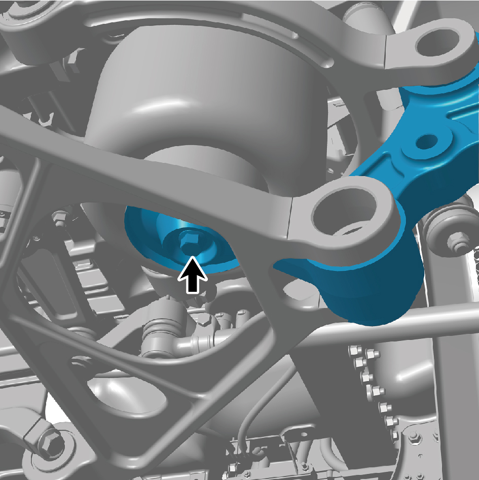
kingpin assembly.
Torque : (199 +/- 18.5)ft lbs
3
Install the swing arm outside pivot (left).
4
Install the Front shock absorber lower mounting bracket.
5
Install the ABS sensor.
6
Install the left steering arm.
7
Install the hub bearing unit (left).
8
Install the brake disc (left).
9
Install the hub flange assembly (left).
10
Install the left front brake assembly.
11
Install the brake chamber (left).
12
Install the guide wheel (left).
13
Lower the front end of the vehicle.
14
Connect the battery negative cable.
15
Close the front flip cover plate.
16
Close the door.
8.6.3.20 Replacement of Right Steering Knuckle with Kingpin Assembly
Knuckle with Kingpin Assembly
Removal Procedures
1
Release air pressure from the brake system.
2
Open the door.
3
Open the front flip cover plate.
4
Disconnect the battery negative cable.
caution
power down the high-voltage system before
disconnecting the negative pole of the storage
battery.
5
Jack the front end of the vehicle.
6
Remove the guide wheel (right).
7
Remove the brake chamber (right).
8
Remove the right front brake assembly.
9
Remove the hub flange assembly (right).
10
Remove the brake disc (right).
11
Remove the hub bearing unit (right).
12
Remove the right steering arm.
13
Remove the ABS sensor.
14
Remove the Front shock absorber lower mounting
bracket.
15
Remove the swing arm outside pivot (right).
16
Use a tool to support the right steering knuckle with
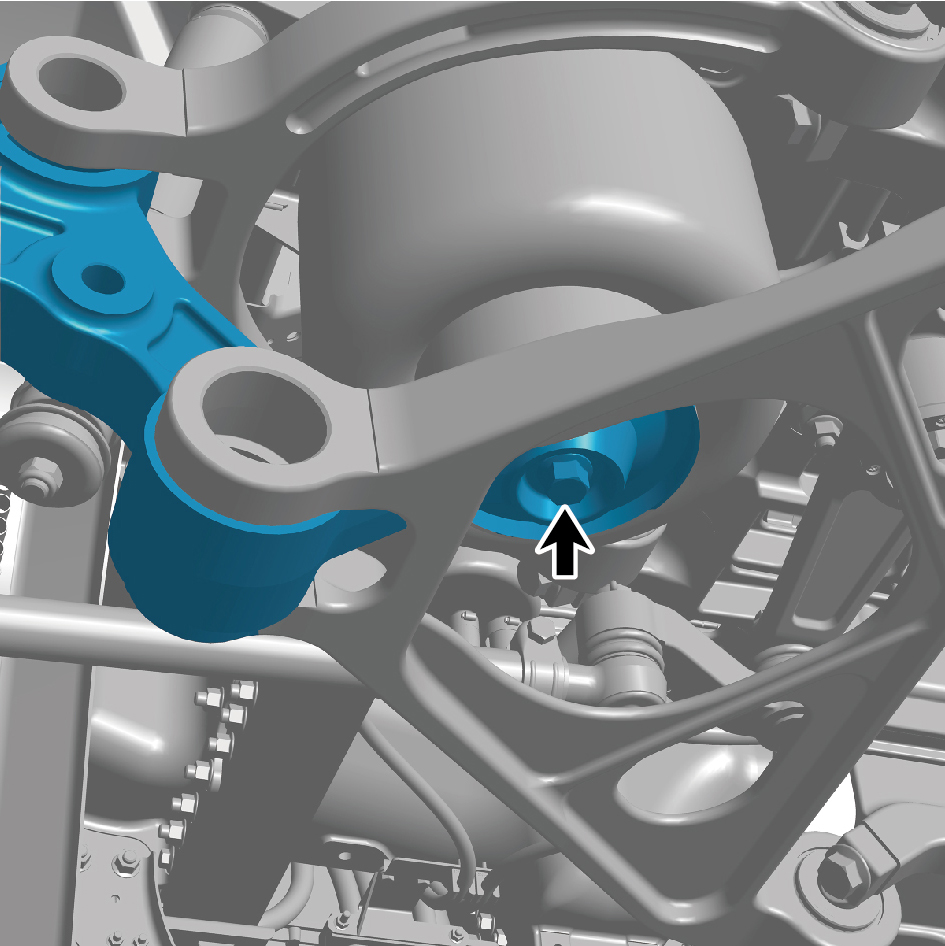
kingpin assembly.
17
Remove 1 fixing bolt of the right steering knuckle with
kingpin assembly.
18
Remove the right steering knuckle with kingpin assembly.
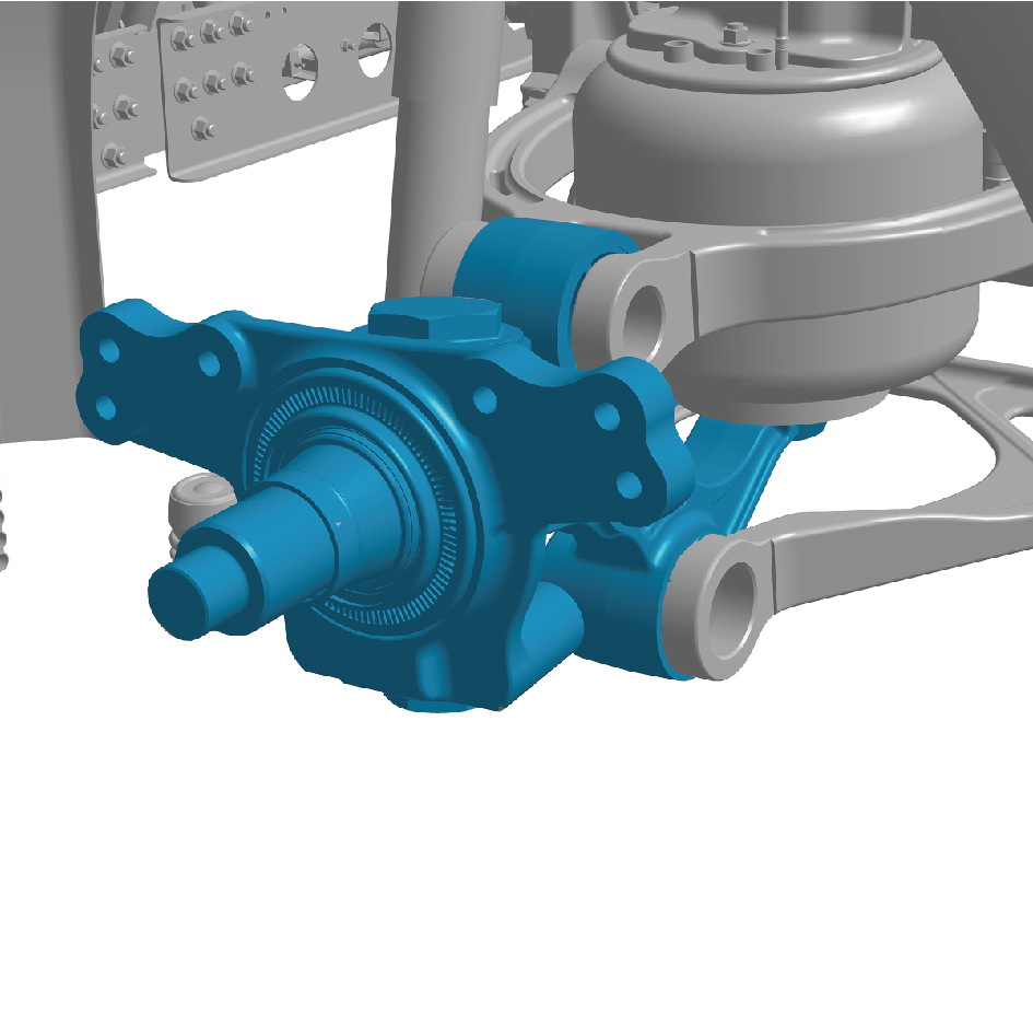
Installation Procedures
1
Move the right steering knuckle with kingpin assembly to
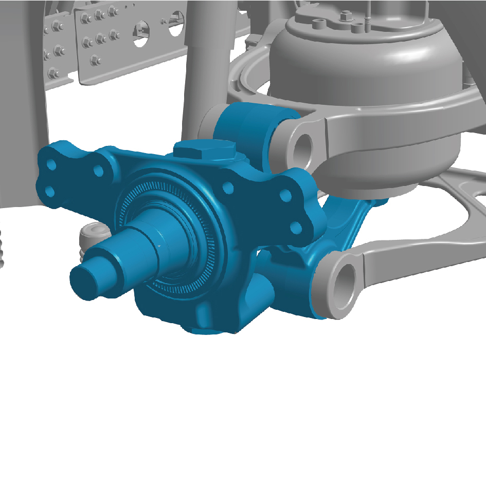
the mounting position.
2
Install 1 fixing bolt of the right steering knuckle with
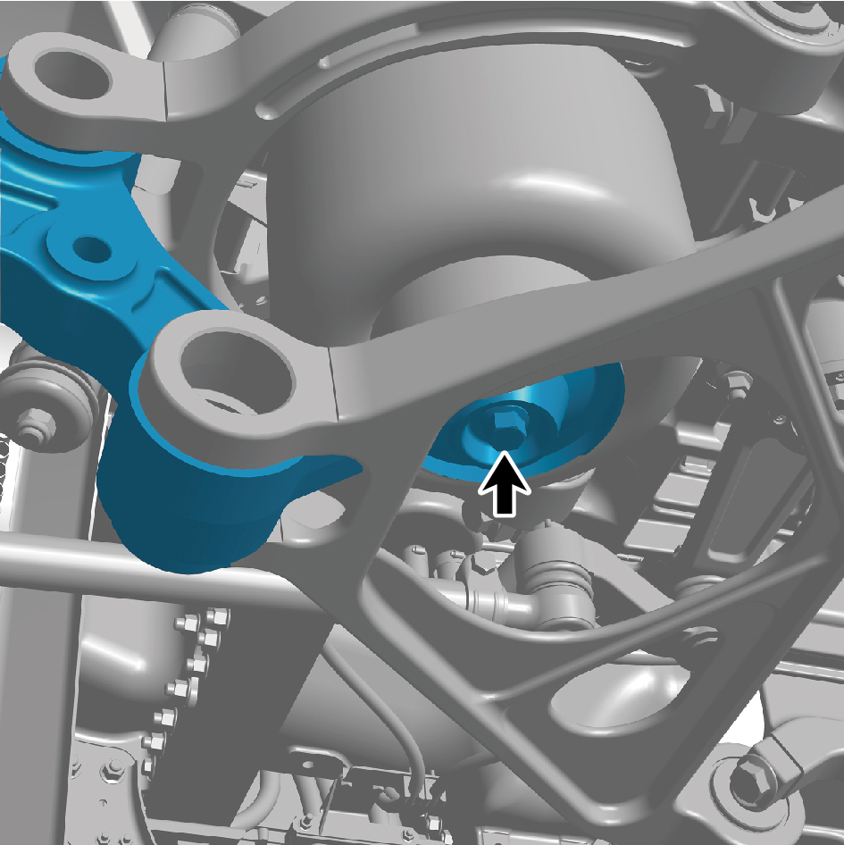
kingpin assembly.
Torque : (199 +/- 18.5)ft lbs
3
Install the swing arm outside pivot (right).
4
Install the Front shock absorber lower mounting bracket.
5
Install the ABS sensor.
6
Install the right steering arm.
7
Install the hub bearing unit (right).
8
Install the brake disc (right).
9
Install the hub flange assembly (left).
10
Install the right front brake assembly.
11
Install the brake chamber (right).
12
Install the guide wheel (right).
13
Lower the front end of the vehicle.
14
Connect the battery negative cable.
15
Close the front flip cover plate.
16
Close the door.
8.6.3.21 Replacement of Brake Chamber
Removal Procedures
1
Release air pressure from the brake system.
2
Jack the front end of the vehicle.
3
Remove the guide wheel (left).
4
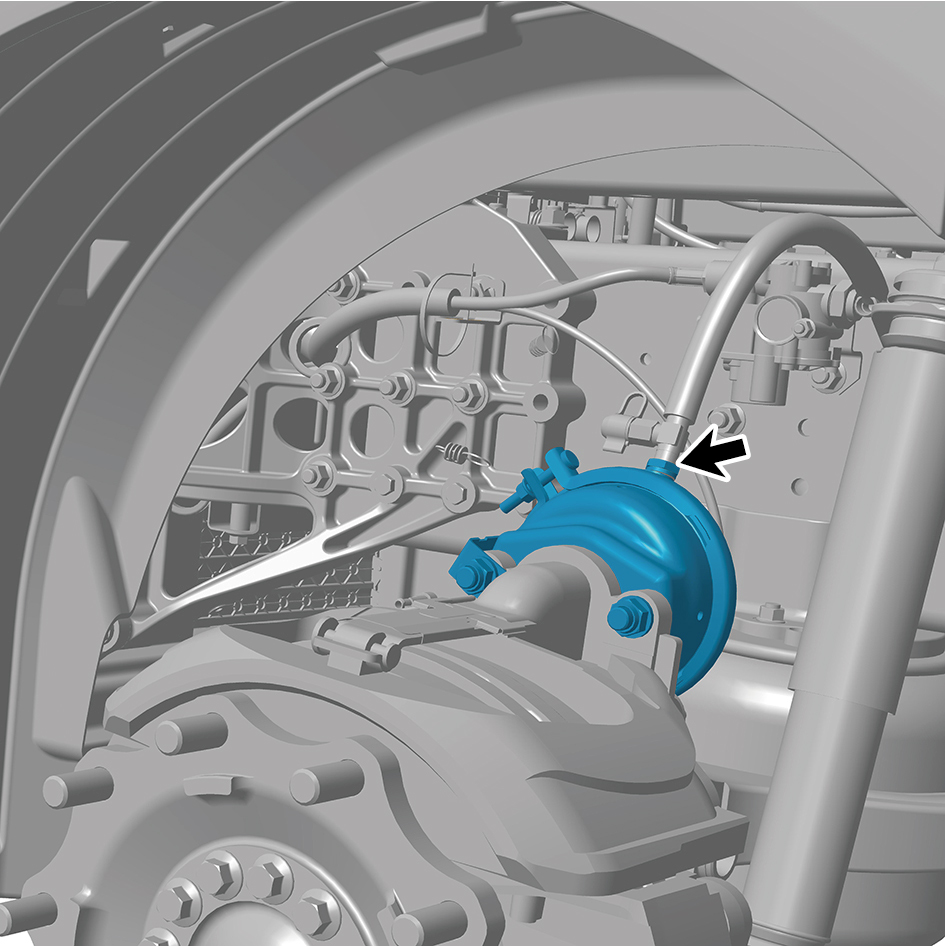
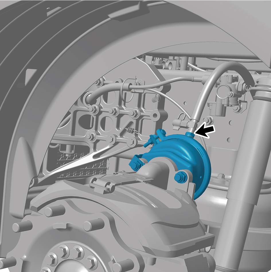
Disconnect 1 air pipe of the brake chamber (left).
5
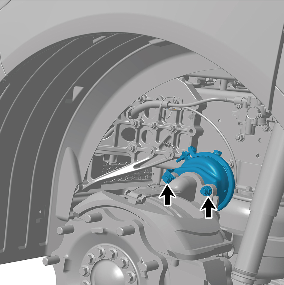
Remove 2 fixing nuts of the brake chamber (left).
6
Remove the brake chamber (left).
Installation Procedures
1
Move the brake chamber (left) to the mounting position.
2
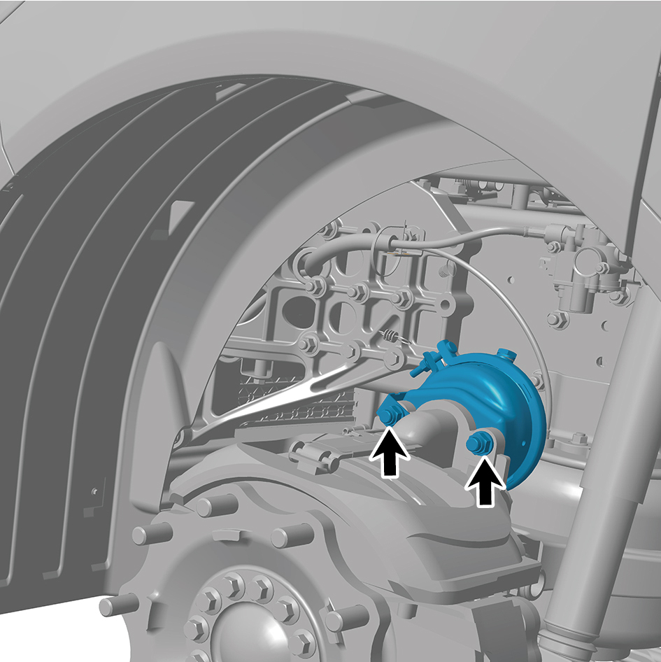
Install 2 fixing nuts of the brake chamber (left).
Torque: 133 +/- 7.5 (ft lbs)
3
Connect 1 air pipe of the brake chamber (left).
4
Install the guide wheel (left).
5
Lower the front end of the vehicle.
8.6.3.22 Replacement of Brake Chamber
Removal Procedures
1
Release air pressure from the brake system.
2
Jack the front end of the vehicle.
3
Remove the guide wheel (right).
4
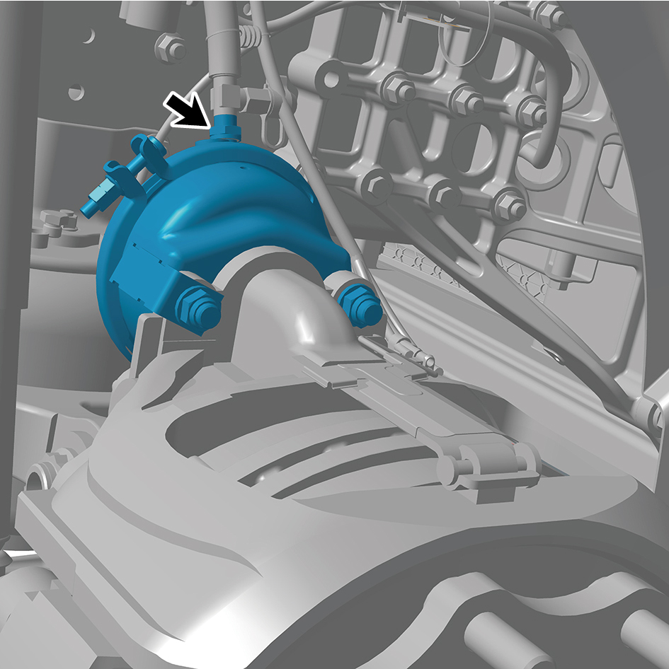
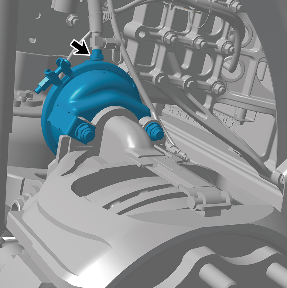
Disconnect 1 air pipe of the brake chamber (right).
5
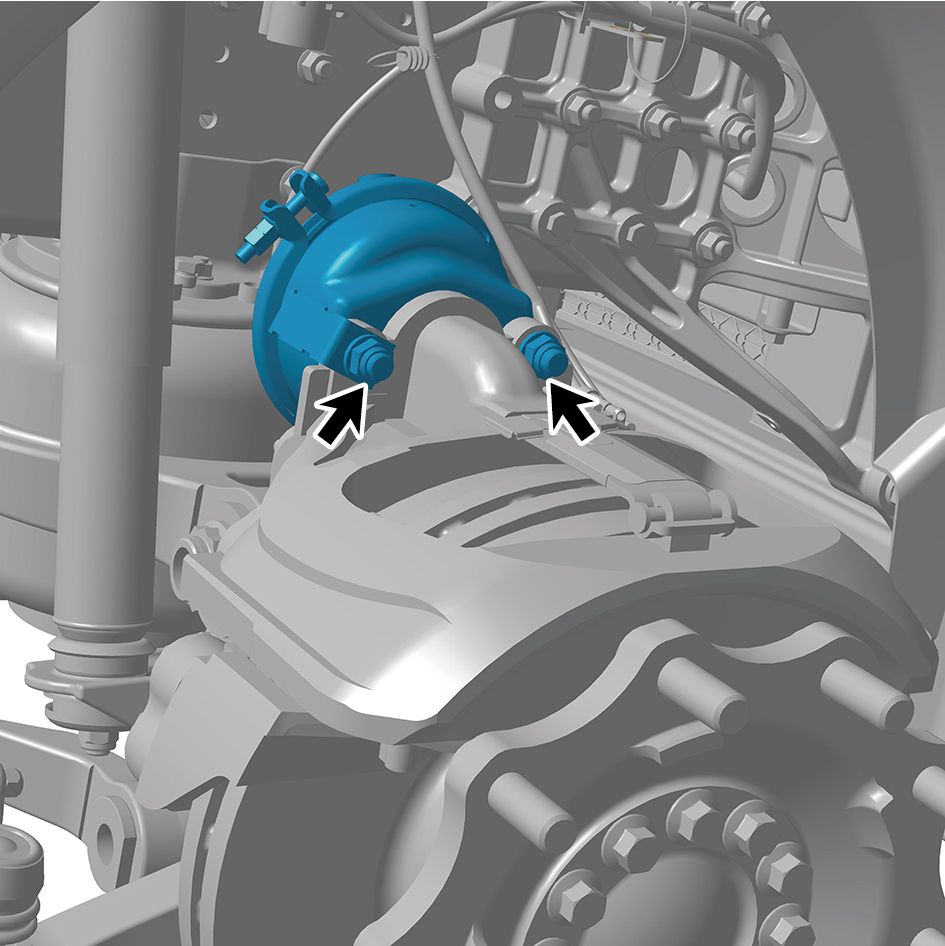
Remove 2 fixing nuts of the brake chamber (right).
6
Remove the brake chamber (right).
Installation Procedures
1
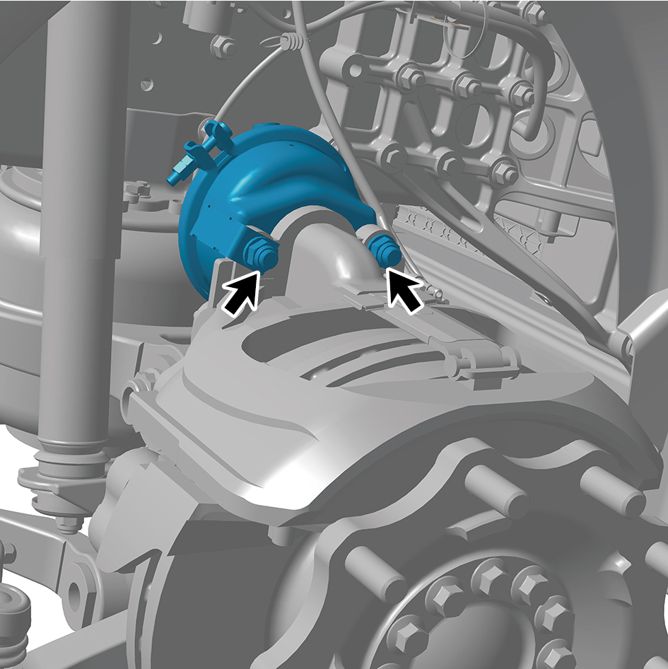
Move the brake chamber (right) to the mounting position.
2
Install 2 fixing nuts of the brake chamber (right).
Torque:133 +/- 7.5 (ft lbs)
3
Connect 1 air pipe of the brake chamber (right).
4
Install the guide wheel (right).
5
Lower the front end of the vehicle.
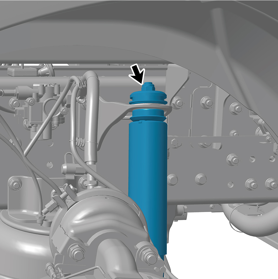
8.6.3.23 Replacement of Front Shock Absorber Assembly
Assembly
Removal Procedures
1
Jack the front end of the vehicle.
2
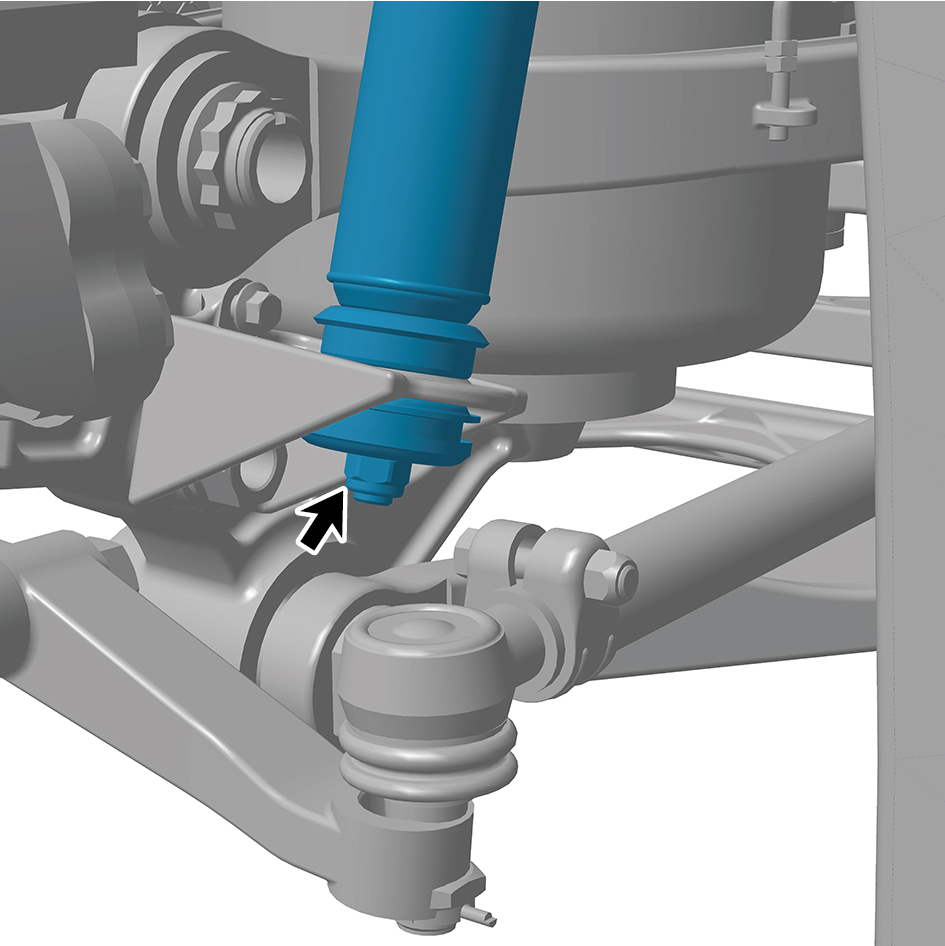
Remove 2 fixing nuts of the front shock absorber
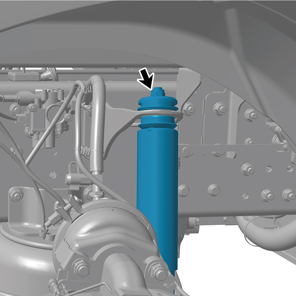
assembly, and remove the front shock absorber assembly.
Installation Procedures
1
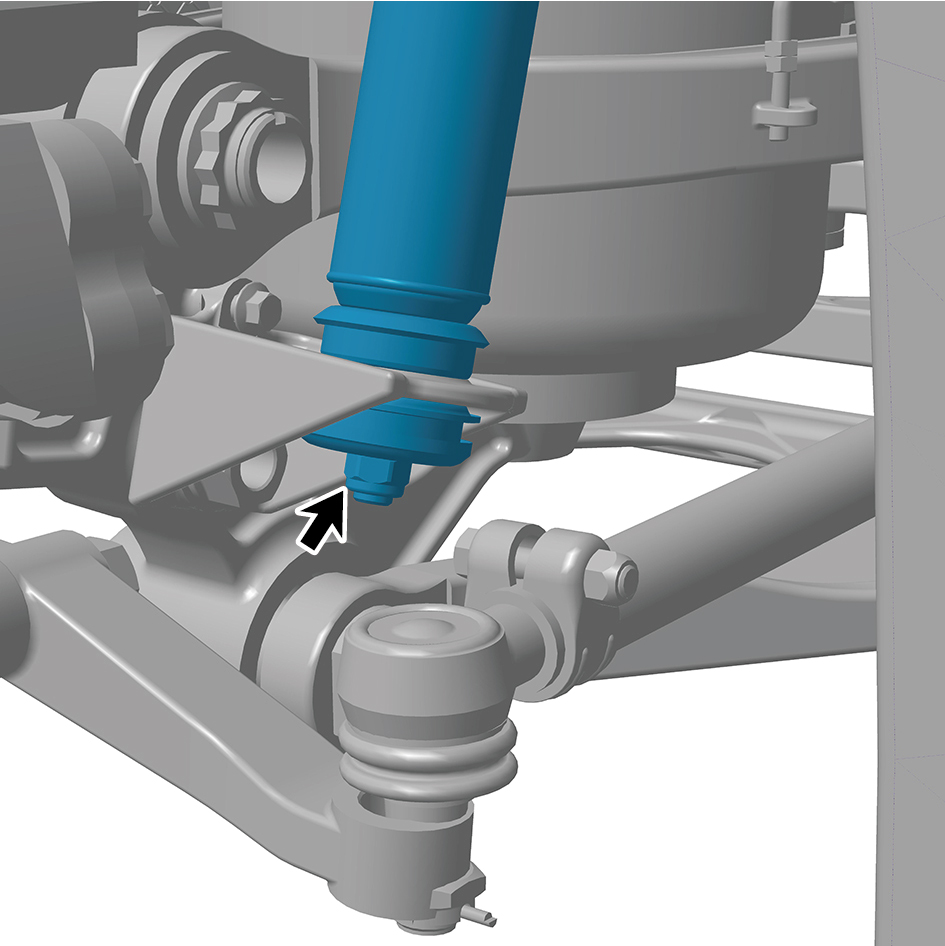
Move the front shock absorber assembly to the mounting
position.
2
Install 2 fixing nuts of the front shock absorber assembly.
Torque:66 +/- 7.5 (ft lbs)
3
Lower the front end of the vehicle.
8.6.3.24 Replacement of Wheel Hub Flange
Removal Procedures
1
Jack the front end of the vehicle.
2
Remove the guide wheel (right).
3
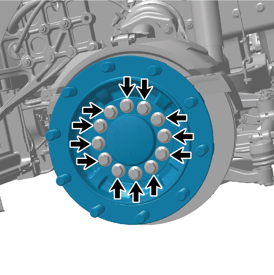
Remove the twelve retaining bolts of the wheel hub flange.
4
Remove the wheel hub flange.
Installation Procedures
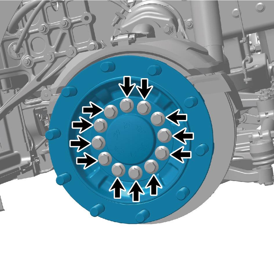
1
Move the wheel hub flange to the mounting position.
2
Install the 12 fixing bolts of the wheel hub flange.
3
Install the guide wheel (right).
4
Lower the front end of the vehicle.
8.6.3.25 Replacement of Wheel Speed Sensor
Removal Procedures
1
Disconnect the battery negative cable.
caution
power down the high-voltage system before
disconnecting the negative pole of the storage
battery.
2
Jack the front end of the vehicle.
3
Remove the guide wheel (left).
4
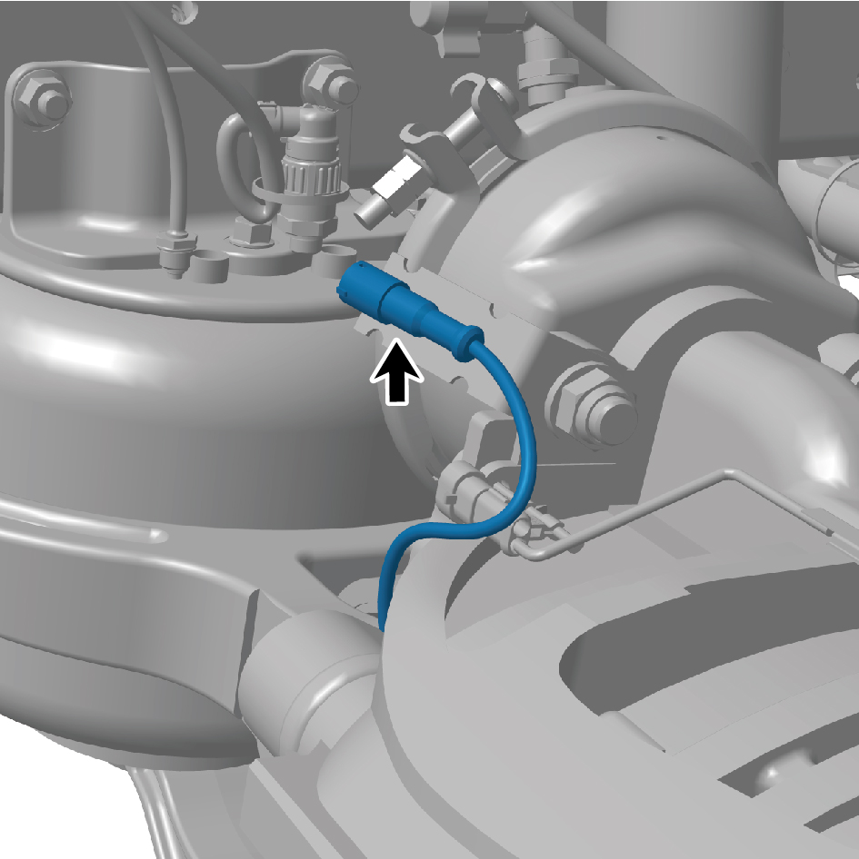
Remove the cable tie.
5
Disconnect the wiring harness at both ends of the wheel
speed sensor and remove the sensor.
Installation Procedures
1
Position the wheel speed sensor at the mounting location
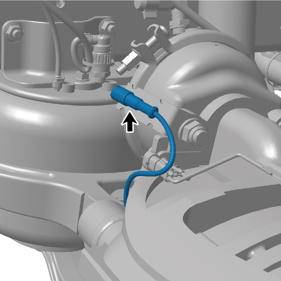
and connect the wiring harness to both ends of the
sensor.
2
Install cable tie.
3
Install the guide wheel(left).
4
Lower the front end of the vehicle.
5
Connect the battery negative cable.