← Back to Contents
8 Chassis / 8.2 Vehicle Frame Device | PDF pages 1815-1849
8.2 Vehicle Frame Device
8.2 Vehicle Frame Device
8.2.1 Specifications
8.2.1.1 Fastener Specifications
Range Of Torque
Fastener Specifications
Specifications
Foot Pounds of Torque (ft lbs)
NCM - fixing bolts connecting the
battery pack assembly (AVIC 161Ah) to
88.5 +/- 6 (ft lbs)
M12
the battery support
NCM - fixing nut connecting battery
pack assembly (AVIC 161Ah) to battery
88.5 +/- 6 (ft lbs)
M12
support
The fixing bolt connecting the bottom
inclined beam bracket 2 to the frame
88.5 +/- 6 (ft lbs)
M12
assembly
The fixing nut connecting the bottom
inclined beam bracket 2 to the frame
88.5 +/- 6 (ft lbs)
M12
assembly
The fixing bolts connecting the lower
protective installation bracket to the
420 +/- 14.75 (ft lbs)
M20
frame assembly
The fixing bolts connecting the front
155 +/- 14.75 (ft lbs)
M14
beam and the frame assembly
The fixing nut connecting the front beam
155 +/- 14.75 (ft lbs)
M14
and the frame assembly
The fixing bolts connecting the middle
cast crossbeam and the frame
155 +/- 14.75 (ft lbs)
M14
assembly
The fixing nut connecting the middle
cast crossbeam and the frame
155 +/- 14.75 (ft lbs)
M14
assembly
The fixing nut connecting the middle
cast crossbeam and the frame
155 +/- 14.75 (ft lbs)
M14
assembly
The fixing nut connecting the middle
longitudinal beam and the frame
155 +/- 14.75 (ft lbs)
M14
assembly
The fixing bolt connecting the internal
battery support (NCM) to the frame
155 +/- 14.75 (ft lbs)
M14
assembly
Range Of Torque
Fastener Specifications
Specifications
Foot Pounds of Torque (ft lbs)
The fixing nut connecting the internal
battery support (NCM) to the frame
155 +/- 14.75 (ft lbs)
M14
assembly
The fixing bolt connecting the external
battery support (NCM) to the frame
155 +/- 14.75 (ft lbs)
M14
assembly
The fixing nut connecting the external
battery support (NCM) to the frame
155 +/- 14.75 (ft lbs)
M14
assembly
The fixing bolts connecting the external
battery mounting plate to the frame
155 +/- 14.75 (ft lbs)
M14
assembly
The fixing nut connecting the external
battery mounting plate to the frame
155 +/- 14.75 (ft lbs)
M14
assembly
The fixing bolts connecting the internal
battery mounting plate to the frame
155 +/- 14.75 (ft lbs)
M14
assembly
The fixing nut connecting the internal
battery mounting plate to the frame
155 +/- 14.75 (ft lbs)
M14
assembly
The fixing bolts connecting the lining
155 +/- 14.75 (ft lbs)
M14
beam and the frame assembly
The fixing nut connecting the lining
155 +/- 14.75 (ft lbs)
M14
beam and the frame assembly
The fixing bolts connecting the tail
155 +/- 14.75 (ft lbs)
M14
crossbeam and the frame assembly
The fixing nut connecting the tail
155 +/- 14.75 (ft lbs)
M14
crossbeam and the frame assembly
The fixing bolts connecting the bThe
fixing bolts connecting the first
155 +/- 14.75 (ft lbs)
crossbeam and the front connecting
M14
beameam and the front connecting
beam
The fixing bolt connecting the first
155 +/- 14.75 (ft lbs)
crossbeam 2 and the front connecting
M14
beam
Range Of Torque
Fastener Specifications
Specifications
Foot Pounds of Torque (ft lbs)
Fixed bolts connecting the pipe beam
516 +/- 37 (ft lbs)
M22
and X-shaped control arm assembly
The fixing bolts connecting the pipe
155 +/- 14.75 (ft lbs)
M14
beam and the frame assembly
8.2.2 Dismantling and Installation
8.2.2.1 Replacement of Frame Assembly
Removal Procedures
1
Release air pressure from the brake system.
2
Open the door.
3
Open the front flip cover plate.
4
Disconnect the battery negative cable.
5
Perform power-off of high voltage system.
6
Recycle A/C refrigerant.
7
Jack the front end of the vehicle.
8
Drain the transmission hydraulic oil.
9
Drain coolant from the power system.
10
Drain coolant from battery thermal management system.
11
Remove the left front wheel housing body.
12
Remove the right front wheel housing body.
13
Remove the left front wheel housing rear body.
14
Remove the right front wheel housing rear body.
15
Remove the roof deflector body.
16
Remove the roof deflector middle bracket.
17
Remove the left deflector upper body.
18
Remove the roof deflector mounting bracket.
19
Remove the left deflector lower body.
20
Remove the upper deflector mounting bracket.
21
Remove the right deflector upper body.
22
Remove the right deflector lower body.
23
Remove the back integrated bracket side cover plate
assembly (left).
24
Remove the back integrated bracket side cover plate
assembly (right).
25
Remove the back integrated bracket middle cover plate
assembly.
26
Remove the back integrated bracket upper cover plate
filler cap.
27
Remove the back integrated bracket upper cover plate.
28
Remove the engine compartment trim panel body.
29
Remove the through-type lamp.
30
Remove the front MMW radar shield.
31
Remove the forward MMW radar.
32
Remove the front MMW radar adapter bracket.
33
Remove the left cover plate of the corner radar.
34
Remove the right cover plate of the corner radar.
35
Remove the front bumper assembly.
36
Remove the left physical exterior rearview mirror
assembly.
37
Remove the primary wiper arm blade assembly (nozzle
and hose).
38
Remove the front windshield cover plate assembly.
39
Remove the left fender trim strip.
40
Remove the left fender assembly.
41
Remove the left front combination lamp.
42
Remove the left headlamp.
43
Remove the left headlamp bracket.
44
Remove the right triangular cover plate assembly.
45
Remove the right fender trim strip.
46
Remove the right fender assembly.
47
Remove the right front combination lamp.
48
Remove the right headlamp.
49
Remove the right headlamp bracket.
50
Remove the left side wall lower trim panel assembly.
51
Remove the side wall upper mounting bracket assembly
2.
52
Remove the left side wall mounting bracket 1.
53
Remove the left side wall mounting bracket 2.
54
Remove the left side wall lower trim panel mounting frame
assembly.
55
Remove the lamp (upper).
56
Remove the lamp (lower).
57
Remove the boarding step body assembly.
58
Remove the boarding step bracket.
59
Remove the upper wheel housing connecting bracket.
60
Remove the lower wheel housing connecting bracket.
61
Remove the boarding step tubular beam.
62
Remove the frame main truss.
63
Remove the BIW assembly.
64
Remove the electric horn assembly - low-pitch.
65
Remove the electric horn assembly - high-pitch.
66
Remove the sealing cross beam.
67
Remove the MMW radar bracket.
68
Remove the front lower protection assembly.
69
Remove the deflector assembly.
70
Remove the condenser.
71
Remove the front end module.
72
Remove the guide wheel (left).
73
Remove the front spring left upper mounting plate.
74
Remove the pressure sensor assembly.
75
Remove the front air spring assembly (left).
76
Remove the brake chamber (left).
77
Remove the front shock absorber assembly (left).
78
Remove the left front wheel end assembly.
79
Remove the ABS sensor (left).
80
Remove the guide wheel (right).
81
Remove the front spring right upper mounting plate.
82
Remove the front air spring assembly (right).
83
Remove the brake chamber (right).
84
Remove the front shock absorber assembly (right).
85
Remove the right front wheel end assembly.
86
Remove the ABS sensor (right).
87
Remove the steering fluid reservoir.
88
Remove the electric oil pump.
89
Remove the low pressure oil pipe.
90
Remove the high pressure oil pipe.
91
Remove the A/C compressor assembly.
92
Remove the integrated EHPS assembly.
93
Remove the driving rocker arm.
94
Remove the driven rocker arm.
95
Remove the ABS solenoid valve assembly.
96
Remove the brake hose assembly (left).
97
Remove the ABS solenoid valve bracket.
98
Remove the brake hose assembly (right).
99
Remove the brake pipe bundle assembly.
100
Remove the single channel module assembly.
101
Remove the electronic water pump (front).
102
Remove the electronic water pump (rear).
103
Remove the walking platform.
104
Remove the shock absorber assembly (rear).
105
Remove the corrugated plate.
106
Removal the fifth wheel assembly.
107
Remove the drive wheel (front left).
108
Remove the rear left wheel housing middle body
assembly.
109
Removal the rear wheel housing left front assembly.
110
Remove the rear air spring assembly - 260 (left front).
111
Remove the rear air spring assembly - 280 (left front).
112
Remove the longitudinal thrust rod assembly.
113
Remove the rear spring U-bolt.
114
Remove the rear spring U-bolt 2.
115
Remove the balance beam (left).
116
Remove the drive wheel (right front)
117
Remove the rear wheel housing right front assembly.
118
Remove the rear air spring assembly - 260 (right front).
119
Remove the rear air spring assembly - 280 (right front).
120
Remove the balance beam (right).
121
Remove the X-shaped control arm assembly (front).
122
Remove the E-Axle Device - intermediate axle.
123
Remove the drive wheel (rear left).
124
Remove the height adjustment device assembly (left).
125
Remove the rear air spring assembly - 260 (rear left).
126
Remove the rear air spring assembly - 280 (rear left).
127
Remove the drive wheel (rear right).
128
Remove the height adjustment device assembly (right).
129
Remove the rear air spring assembly - 260 (rear right).
130
Remove the rear air spring assembly - 280 (rear right).
131
Remove the dual channel module assembly.
132
Remove the X-shaped control arm assembly (rear).
133
Remove the E-Axle Device - rear axle.
134
Remove the frame assembly.
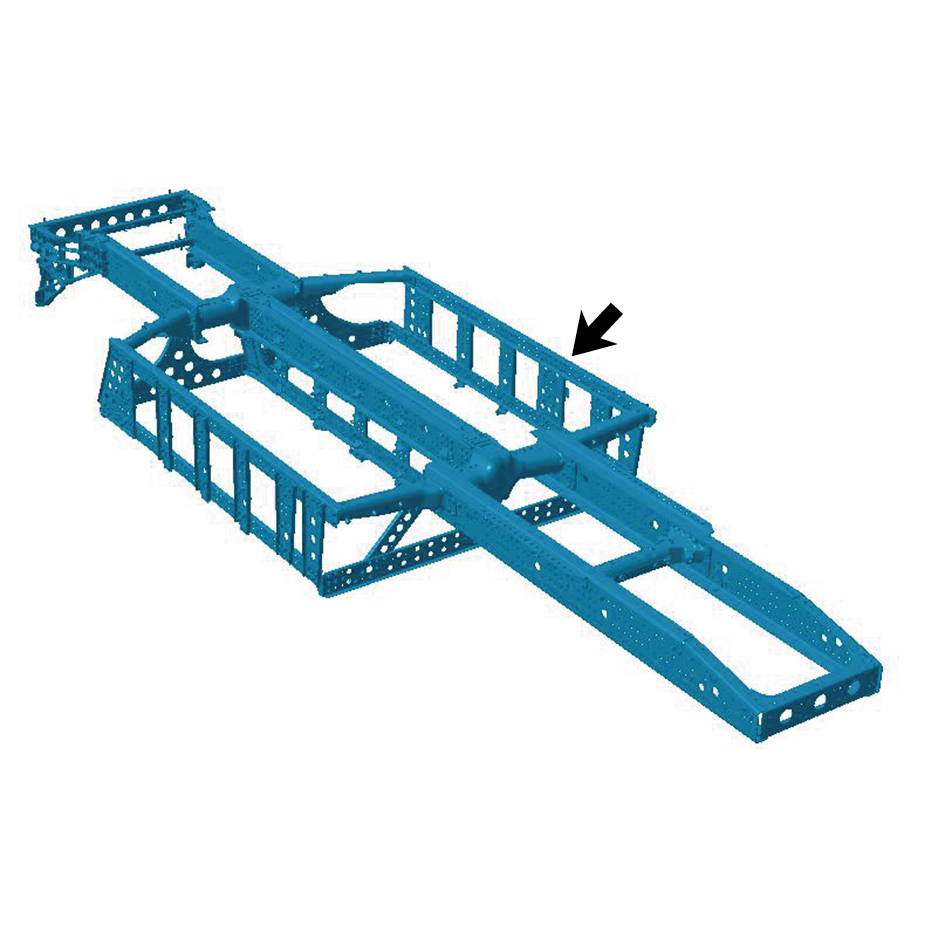
Installation Procedures
1
Install the frame assembly.
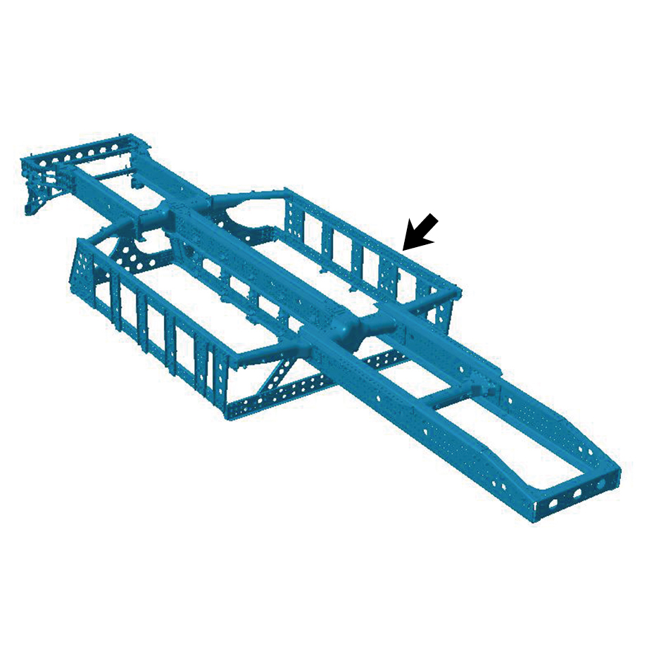
2
Install the E-Axle Device - rear axle.
3
Install the X-shaped control arm assembly (rear).
4
Install the dual channel module assembly.
5
Install the rear air spring assembly - 280 (rear right).
6
Install the rear air spring assembly - 260 (rear right).
7
Install the height adjustment device assembly (right).
8
Install the drive wheel (rear right).
9
Install the rear air spring assembly - 280 (rear left).
10
Install the rear air spring assembly - 260 (rear left).
11
Install the height adjustment device assembly (left).
12
Install the drive wheel (rear left).
13
Install the E-Axle Device - intermediate axle.
14
Install the X-shaped control arm assembly (front).
15
Install the balance beam (right).
16
Install the rear air spring assembly - 280 (right front).
17
Install the rear air spring assembly - 260 (right front).
18
Install the rear wheel housing right front assembly.
19
Install the drive wheel (right front).
20
Install the balance beam (left).
21
Install the rear spring U-bolt 2.
22
Install the rear spring U-bolt.
23
Install the longitudinal thrust rod assembly.
24
Install the rear air spring assembly - 280 (left front).
25
Install the rear air spring assembly - 260 (left front).
26
Install the rear wheel housing left front assembly.
27
Install the drive wheel (left front).
28
Install the fifth wheel assembly.
29
Install the corrugated plate.
30
Install the shock absorber assembly (rear).
31
Install the walking platform.
32
Install the electronic water pump (rear).
33
Install the electronic water pump (front).
34
Install the single channel module assembly.
35
Install the brake pipe bundle assembly.
36
Install the brake hose assembly (right).
37
Install the ABS solenoid valve bracket.
38
Install the brake hose assembly (left).
39
Install the ABS solenoid valve assembly.
40
Install the driven rocker arm.
41
Install the driving rocker arm.
42
Install the integrated EHPS assembly.
43
Install the A/C compressor assembly.
44
Install the high pressure oil pipe.
45
Install the low pressure oil pipe.
46
Install the electric oil pump.
47
Install the steering fluid reservoir.
48
Install the ABS sensor (right).
49
Install the right front wheel end assembly.
50
Install the front shock absorber assembly (right).
51
Install the brake chamber (right).
52
Install the front air spring assembly (right).
53
Install the front spring right upper mounting plate.
54
Install the guide wheel (right).
55
Install the ABS sensor (left).
56
Install the left front wheel end assembly.
57
Install the front shock absorber assembly (left).
58
Install the brake chamber (left).
59
Install the front air spring assembly (left).
60
Install the pressure sensor assembly.
61
Install the front spring left upper mounting plate.
62
Install the guide wheel (left).
63
Install the front end module.
64
Install the condenser.
65
Install the deflector assembly.
66
Install the front lower protection assembly.
67
Install the MMW radar bracket.
68
Install the sealing cross beam.
69
Install the electric horn assembly - high-pitch.
70
Install the electric horn assembly - low-pitch.
71
Install the BIW assembly.
72
Install the frame main truss.
73
Install the right deflector lower body.
74
Install the left deflector lower body.
75
Install the boarding step tubular beam.
76
Install the lower wheel housing connecting bracket.
77
Install the upper wheel housing connecting bracket.
78
Install the boarding step bracket.
79
Install the boarding step body assembly.
80
Install the lamp (lower).
81
Install the lamp (upper).
82
Install the left side wall lower trim panel mounting frame
assembly.
83
Install the left side wall mounting bracket 2.
84
Install the left side wall mounting bracket 1.
85
Install the side wall upper mounting bracket assembly 2.
86
Install the left side wall lower trim panel assembly.
87
Install the right headlamp bracket.
88
Install the right headlamp.
89
Install the right front combination lamp.
90
Install the right fender assembly.
91
Install the right fender trim strip.
92
Install the right triangular cover plate assembly.
93
Install the left headlamp bracket.
94
Install the left headlamp.
95
Install the left front combination lamp.
96
Install the left fender assembly.
97
Install the left fender trim strip.
98
Install the front windshield cover plate assembly.
99
Install the primary wiper arm blade assembly (nozzle and
hose).
100
Install the left physical exterior rearview mirror assembly.
101
Install the front bumper assembly.
102
Install the right cover plate of the corner radar.
103
Install the left cover plate of the corner radar.
104
Install the front MMW radar adapter bracket.
105
Install the forward MMW radar.
106
Install the front MMW radar shield.
107
Install the through-type lamp.
108
Install the engine compartment trim panel body.
109
Install the back integrated bracket upper cover plate.
110
Install the back integrated bracket upper cover plate filler
cap.
111
Install the back integrated bracket middle cover plate
assembly.
112
Install the back integrated bracket side cover plate
assembly (right).
113
Install the back integrated bracket side cover plate
assembly (left).
114
Install the right deflector upper body.
115
Install the upper deflector mounting bracket.
116
Install the deflector mounting bracket.
117
Install the left deflector upper body.
118
Install the roof deflector middle bracket.
119
Install the roof deflector body.
120
Install the rear end-outline marker lamp mounting bracket.
121
Install the rear end-outline marker lamp.
122
Install the right front wheel housing rear body.
123
Install the left front wheel housing rear body.
124
Install the right front wheel housing body.
125
Install the left front wheel housing body.
126
Fill coolant in the battery thermal management system.
127
Lower the front end of the vehicle.
128
Fill with A/C refrigerant.
129
Perform power-on of the high voltage system.
130
Connect the battery negative cable.
131
Close the front flip cover plate.
132
Close the door.
8.2.2.2 Replacement of Head Cross Beam 2
Removal Procedures
1
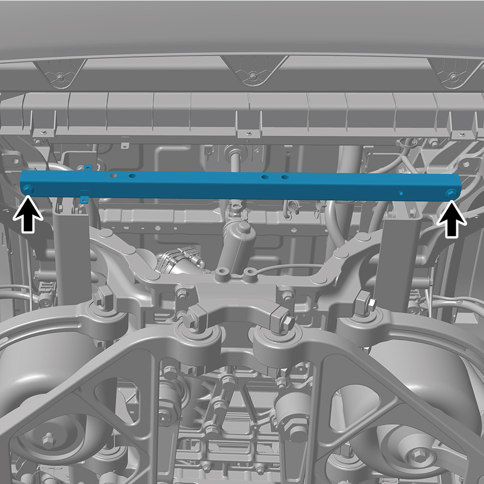
Remove 2 fixing bolts and nuts of the head cross beam 2.
2
Remove the head cross beam 2.
Installation Procedures
1
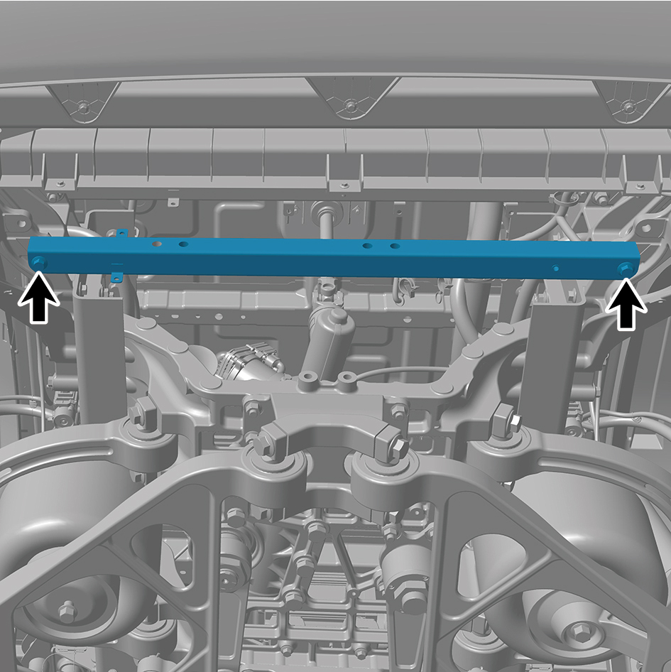
Move the head cross beam 2 to the mounting position.
2
Install 2 fixing bolts and nuts of the head cross beam 2.
Torque:140 - 170 (ft lbs)
8.2.2.3 Replacement of Left Front Joint Beam
Removal Procedures
1
Release air pressure from the brake system.
2
Open the door.
3
Open the front flip cover plate.
4
Disconnect the battery negative cable.
5
Perform power-off of high voltage system.
6
Recycle A/C refrigerant.
7
Jack the front end of the vehicle.
8
Drain coolant from the power system.
9
Drain coolant from battery thermal management system.
10
Remove the left front wheel housing body.
11
Remove the right front wheel housing body.
12
Remove the left front wheel housing rear body.
13
Remove the right front wheel housing rear body.
14
Remove the roof deflector body.
15
Remove the roof deflector middle bracket.
16
Remove the left deflector upper body.
17
Remove the roof deflector mounting bracket.
18
Remove the left deflector lower body.
19
Remove the upper deflector mounting bracket.
20
Remove the right deflector upper body.
21
Remove the right deflector lower body.
22
Remove the back integrated bracket side cover plate
assembly (left).
23
Remove the back integrated bracket side cover plate
assembly (right).
24
Remove the back integrated bracket middle cover plate
assembly.
25
Remove the back integrated bracket upper cover plate
filler cap.
26
Remove the back integrated bracket upper cover plate.
27
Remove the engine compartment trim panel body.
28
Remove the through-type lamp.
29
Remove the front MMW radar shield.
30
Remove the forward MMW radar.
31
Remove the front MMW radar adapter bracket.
32
Remove the left cover plate of the corner radar.
33
Remove the right cover plate of the corner radar.
34
Remove the front bumper assembly.
35
Remove the left physical exterior rearview mirror
assembly.
36
Remove the primary wiper arm blade assembly (nozzle
and hose).
37
Remove the front windshield cover plate assembly.
38
Remove the left fender trim strip.
39
Remove the left fender assembly.
40
Remove the left front combination lamp.
41
Remove the left headlamp.
42
Remove the left headlamp bracket.
43
Remove the right triangular cover plate assembly.
44
Remove the right fender trim strip.
45
Remove the right fender assembly.
46
Remove the right front combination lamp.
47
Remove the right headlamp.
48
Remove the right headlamp bracket.
49
Remove the left side wall lower trim panel assembly.
50
Remove the side wall upper mounting bracket assembly
2.
51
Remove the left side wall mounting bracket 1.
52
Remove the left side wall mounting bracket 2.
53
Remove the left side wall lower trim panel mounting frame
assembly.
54
Remove the lamp (upper).
55
Remove the lamp (lower).
56
Remove the boarding step body assembly.
57
Remove the boarding step bracket.
58
Remove the upper wheel housing connecting bracket.
59
Remove the lower wheel housing connecting bracket.
60
Remove the boarding step tubular beam.
61
Remove the frame main truss.
62
Remove the BIW assembly.
63
Remove the MMW radar bracket.
64
Remove the front lower protection assembly.
65
Remove the lower protection left mounting support.
66
Remove the sealing cross beam.
67
Remove the VDC assembly.
68
Remove the VDC bracket.
69
Remove the battery rod.
70
Remove the battery pressure plate 3.
71
Remove the battery pressure plate 2.
72
Remove the auxiliary battery.
73
Remove the battery backing plate.
74
Remove Left Junction Box.
75
Remove Right Junction Box.
76
Remove the battery assembly bracket.
77
Removal the head cross beam.
78
Removal the head cross beam 2.
79
Remove the upper wheel housing mounting bracket (left).
80
Disconnect 4 harness connectors of the left front joint
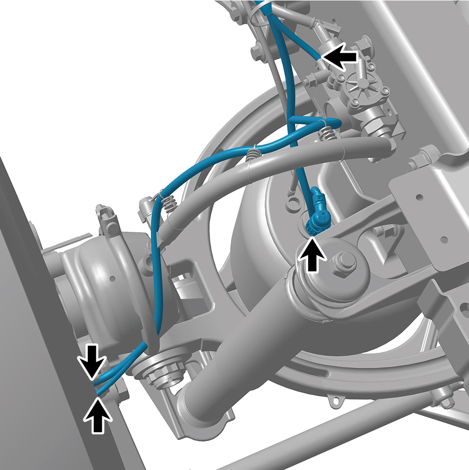
beam.
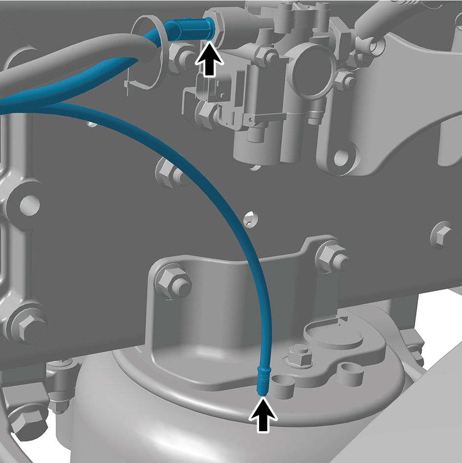
81
Disconnect 2 air pipes of the left front joint beam.
82
Remove 13 fixing bolts and nuts of the left front joint
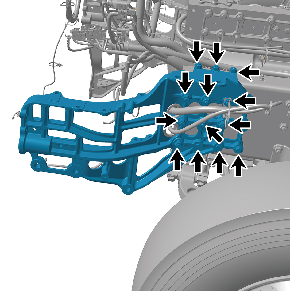
beam.
83
Remove the left front joint beam.
Installation Procedures
1
Move the left front joint beam to the mounting position.
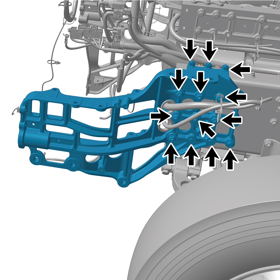
2
Install 13 fixing bolts and nuts of the left front joint beam.
Torque: 140 +/- 170 (ft lbs)
3
Connect 2 air pipes of the left front joint beam.
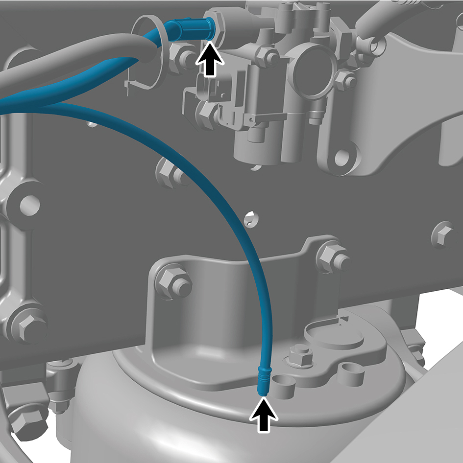
4
Connect 4 harness connectors of the left front joint beam.
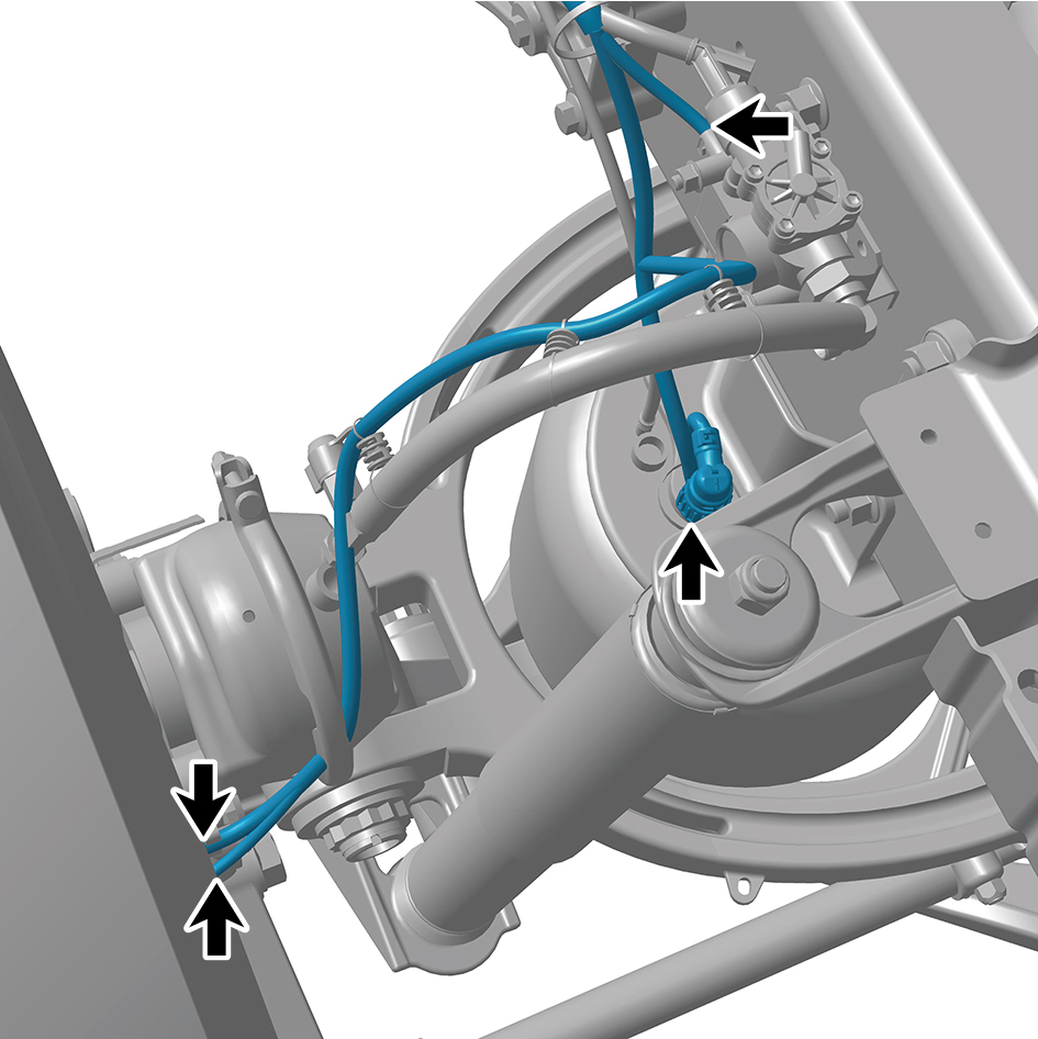
caution
The harness is firmly connected following the
principal of "insert until a click is heard for
confirmation".
5
Install the upper wheel housing mounting bracket (left).
6
Install the head cross beam 2.
7
Install the head cross beam.
8
Install the battery assembly bracket.
9
Install Right Junction Box.
10
Install Left Junction Box.
11
Install the battery backing plate.
12
Install the auxiliary battery.
13
Install the battery pressure plate 2.
14
Install the battery pressure plate 3.
15
Install the battery rod.
16
Install the VDC bracket.
17
Install the VDC assembly.
18
Install the sealing cross beam.
19
Install the lower protection left mounting support.
20
Install the front lower protection assembly.
21
Install the MMW radar bracket.
22
Install the BIW assembly.
23
Install the frame main truss.
24
Install the right deflector lower body.
25
Install the left deflector lower body.
26
Install the boarding step tubular beam.
27
Install the lower wheel housing connecting bracket.
28
Install the upper wheel housing connecting bracket.
29
Install the boarding step bracket.
30
Install the boarding step body assembly.
31
Install the lamp (lower).
32
Install the lamp (upper).
33
Install the left side wall lower trim panel mounting frame
assembly.
34
Install the left side wall mounting bracket 2.
35
Install the left side wall mounting bracket 1.
36
Install the side wall upper mounting bracket assembly 2.
37
Install the left side wall lower trim panel assembly.
38
Install the right headlamp bracket.
39
Install the right headlamp.
40
Install the right front combination lamp.
41
Install the right fender assembly.
42
Install the right fender trim strip.
43
Install the right triangular cover plate assembly.
44
Install the left headlamp bracket.
45
Install the left headlamp.
46
Install the left front combination lamp.
47
Install the left fender assembly.
48
Install the left fender trim strip.
49
Install the front windshield cover plate assembly.
50
Install the primary wiper arm blade assembly (nozzle and
hose).
51
Install the left physical exterior rearview mirror assembly.
52
Install the front bumper assembly.
53
Install the right cover plate of the corner radar.
54
Install the left cover plate of the corner radar.
55
Install the front MMW radar adapter bracket.
56
Install the forward MMW radar.
57
Install the front MMW radar shield.
58
Install the through-type lamp.
59
Install the engine compartment trim panel body.
60
Install the back integrated bracket upper cover plate.
61
Install the back integrated bracket upper cover plate filler
cap.
62
Install the back integrated bracket middle cover plate
assembly.
63
Install the back integrated bracket side cover plate
assembly (right).
64
Install the back integrated bracket side cover plate
assembly (left).
65
Install the right deflector upper body.
66
Install the upper deflector mounting bracket.
67
Install the deflector mounting bracket.
68
Install the left deflector upper body.
69
Install the roof deflector middle bracket.
70
Install the roof deflector body.
71
Install the right front wheel housing rear body.
72
Install the left front wheel housing rear body.
73
Install the right front wheel housing body.
74
Install the left front wheel housing body.
75
Fill coolant in the battery thermal management system.
76
Fill coolant in the power system.
77
Lower the front end of the vehicle.
78
Fill with A/C refrigerant.
79
Perform power-on of the high voltage system.
80
Connect the battery negative cable.
81
Close the front flip cover plate.
82
Close the door.
8.2.2.4 Replacement of Right Front Joint Beam
Removal Procedures
1
Release air pressure from the brake system.
2
Open the door.
3
Open the front flip cover plate.
4
Disconnect the battery negative cable.
5
Perform power-off of high voltage system.
6
Recycle A/C refrigerant.
7
Jack the front end of the vehicle.
8
Drain coolant from the power system.
9
Drain coolant from battery thermal management system.
10
Remove the left front wheel housing body.
11
Remove the right front wheel housing body.
12
Remove the left front wheel housing rear body.
13
Remove the right front wheel housing rear body.
14
Remove the roof deflector body.
15
Remove the roof deflector middle bracket.
16
Remove the left deflector upper body.
17
Remove the roof deflector mounting bracket.
18
Remove the left deflector lower body.
19
Remove the upper deflector mounting bracket.
20
Remove the right deflector upper body.
21
Remove the right deflector lower body.
22
Remove the back integrated bracket side cover plate
assembly (left).
23
Remove the back integrated bracket side cover plate
assembly (right).
24
Remove the back integrated bracket middle cover plate
assembly.
25
Remove the back integrated bracket upper cover plate
filler cap.
26
Remove the back integrated bracket upper cover plate.
27
Remove the engine compartment trim panel body.
28
Remove the through-type lamp.
29
Remove the front MMW radar shield.
30
Remove the forward MMW radar.
31
Remove the front MMW radar adapter bracket.
32
Remove the left cover plate of the corner radar.
33
Remove the right cover plate of the corner radar.
34
Remove the front bumper assembly.
35
Remove the left physical exterior rearview mirror
assembly.
36
Remove the primary wiper arm blade assembly (nozzle
and hose).
37
Remove the front windshield cover plate assembly.
38
Remove the left fender trim strip.
39
Remove the left fender assembly.
40
Remove the left front combination lamp.
41
Remove the left headlamp.
42
Remove the left headlamp bracket.
43
Remove the right triangular cover plate assembly.
44
Remove the right fender trim strip.
45
Remove the right fender assembly.
46
Remove the right front combination lamp.
47
Remove the right headlamp.
48
Remove the right headlamp bracket.
49
Remove the left side wall lower trim panel assembly.
50
Remove the side wall upper mounting bracket assembly
2.
51
Remove the left side wall mounting bracket 1.
52
Remove the left side wall mounting bracket 2.
53
Remove the left side wall lower trim panel mounting frame
assembly.
54
Remove the lamp (upper).
55
Remove the lamp (lower).
56
Remove the boarding step body assembly.
57
Remove the boarding step bracket.
58
Remove the upper wheel housing connecting bracket.
59
Remove the lower wheel housing connecting bracket.
60
Remove the boarding step tubular beam.
61
Remove the frame main truss.
62
Remove the BIW assembly.
63
Remove the MMW radar bracket.
64
Remove the front lower protection assembly.
65
Remove the lower protection right mounting support.
66
Remove the sealing cross beam.
67
Remove the VDC assembly.
68
Remove the VDC bracket.
69
Remove the battery rod.
70
Remove the battery pressure plate 3.
71
Remove the battery pressure plate 2.
72
Remove the auxiliary battery.
73
Remove the battery backing plate.
74
Remove Left Junction Box.
75
Remove Right Junction Box.
76
Remove the battery assembly bracket.
77
Removal the head cross beam.
78
Removal the head cross beam 2.
79
Remove the upper wheel housing mounting bracket
(right).
80
Disconnect 3 harness connectors of the right front joint
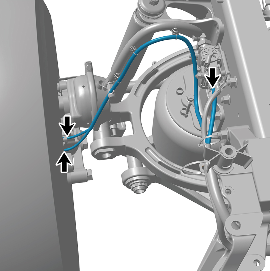
beam.
81
Disconnect 2 air pipes of the right front joint beam.
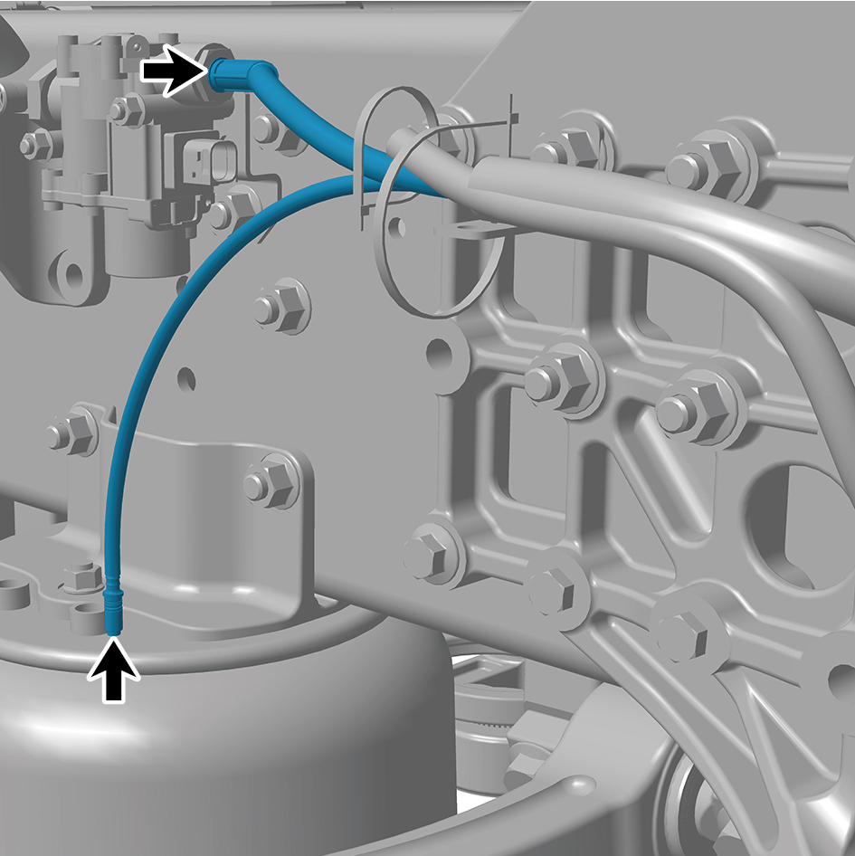
82
Remove 10 fixing bolts and nuts of the right front joint
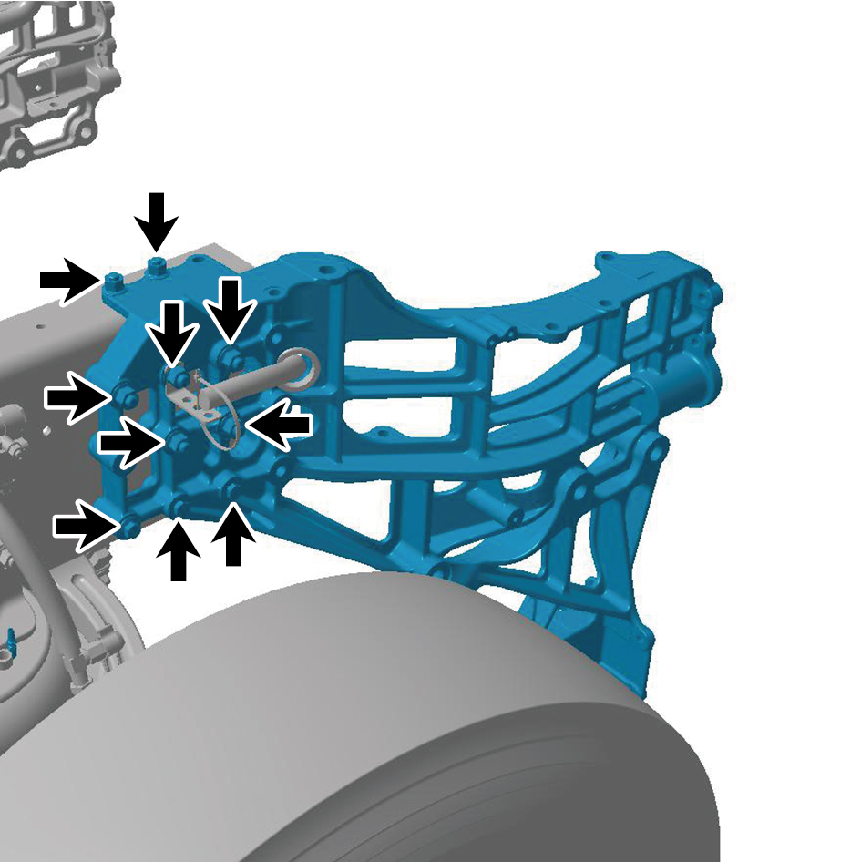
beam.
83
Remove the right front joint beam.
Installation Procedures
1
Move the right front joint beam to the mounting position.
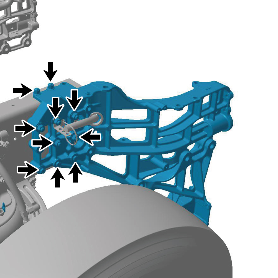
2
Install 10 fixing bolts and nuts of the right front joint beam.
Torque: 140 +/- 170 (ft lbs)
3
Connect 2 air pipes of the right front joint beam.
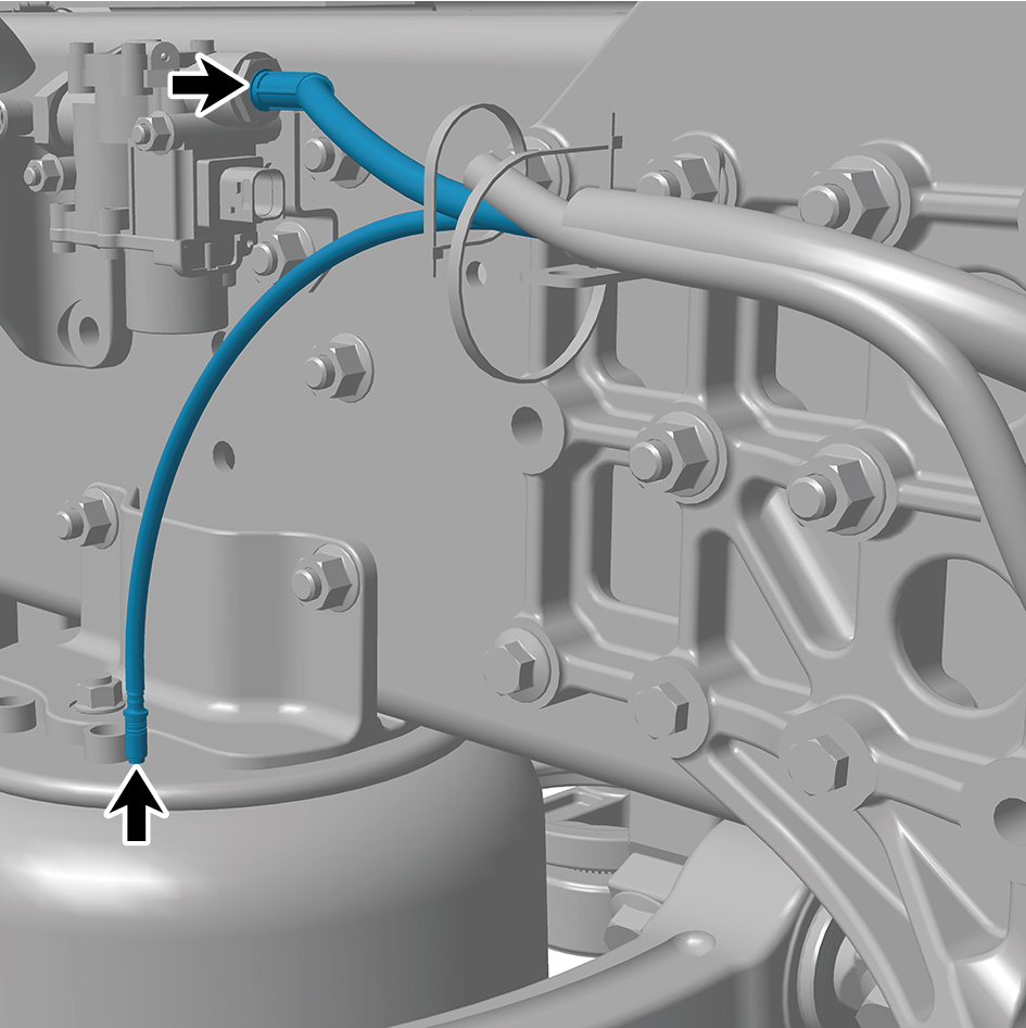
4
Connect 3 harness connectors of the right front joint beam.
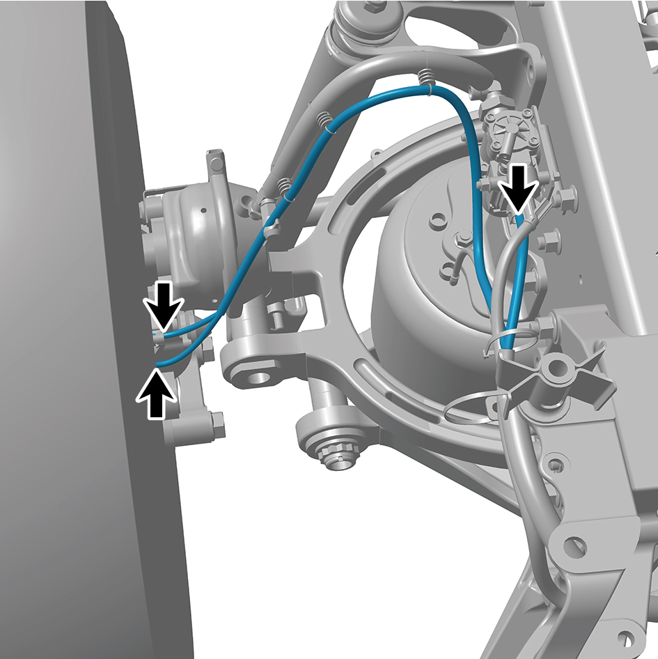
caution
The harness is firmly connected following the
principal of "insert until a click is heard for
confirmation".
5
Install the upper wheel housing mounting bracket (right).
6
Install the head cross beam 2.
7
Install the head cross beam.
8
Install the battery assembly bracket.
9
Install Right Junction Box.
10
Install Left Junction Box.
11
Install the battery backing plate.
12
Install the auxiliary battery.
13
Install the battery pressure plate 2.
14
Install the battery pressure plate 3.
15
Install the battery rod.
16
Install the VDC bracket.
17
Install the VDC assembly.
18
Install the sealing cross beam.
19
Install the lower protection right mounting support.
20
Install the front lower protection assembly.
21
Install the MMW radar bracket.
22
Install the BIW assembly.
23
Install the frame main truss.
24
Install the right deflector lower body.
25
Install the left deflector lower body.
26
Install the boarding step tubular beam.
27
Install the lower wheel housing connecting bracket.
28
Install the upper wheel housing connecting bracket.
29
Install the boarding step bracket.
30
Install the boarding step body assembly.
31
Install the lamp (lower).
32
Install the lamp (upper).
33
Install the left side wall lower trim panel mounting frame
assembly.
34
Install the left side wall mounting bracket 2.
35
Install the left side wall mounting bracket 1.
36
Install the side wall upper mounting bracket assembly 2.
37
Install the left side wall lower trim panel assembly.
38
Install the right headlamp bracket.
39
Install the right headlamp.
40
Install the right front combination lamp.
41
Install the right fender assembly.
42
Install the right fender trim strip.
43
Install the right triangular cover plate assembly.
44
Install the left headlamp bracket.
45
Install the left headlamp.
46
Install the left front combination lamp.
47
Install the left fender assembly.
48
Install the left fender trim strip.
49
Install the front windshield cover plate assembly.
50
Install the primary wiper arm blade assembly (nozzle and
hose).
51
Install the left physical exterior rearview mirror assembly.
52
Install the front bumper assembly.
53
Install the right cover plate of the corner radar.
54
Install the left cover plate of the corner radar.
55
Install the front MMW radar adapter bracket.
56
Install the forward MMW radar.
57
Install the front MMW radar shield.
58
Install the through-type lamp.
59
Install the engine compartment trim panel body.
60
Install the back integrated bracket upper cover plate.
61
Install the back integrated bracket upper cover plate filler
cap.
62
Install the back integrated bracket middle cover plate
assembly.
63
Install the back integrated bracket side cover plate
assembly (right).
64
Install the back integrated bracket side cover plate
assembly (left).
65
Install the right deflector upper body.
66
Install the upper deflector mounting bracket.
67
Install the deflector mounting bracket.
68
Install the left deflector upper body.
69
Install the roof deflector middle bracket.
70
Install the roof deflector body.
71
Install the right front wheel housing rear body.
72
Install the left front wheel housing rear body.
73
Install the right front wheel housing body.
74
Install the left front wheel housing body.
75
Fill coolant in the battery thermal management system.
76
Fill coolant in the power system.
77
Lower the front end of the vehicle.
78
Fill with A/C refrigerant.
79
Perform power-on of the high voltage system.
80
Connect the battery negative cable.
81
Close the front flip cover plate.
82
Close the door.
8.2.2.5 Replacement of Tail Cross Beam
Removal Procedures
1
Release air pressure from the brake system.
2
Open the door.
3
Open the front flip cover plate.
4
Disconnect the battery negative cable.
caution
power down the high-voltage system before
disconnecting the negative pole of the storage
battery.
5
Remove the air reservoir assembly (rear).
6
Remove the license plate lamp.
7
Remove the rear license plate mounting plate assembly.
8
Remove the left rear combination lamp.
9
Remove the right rear combination lamp.
10
Remove the reversing lamp.
11
Remove the rear retro-reflector.
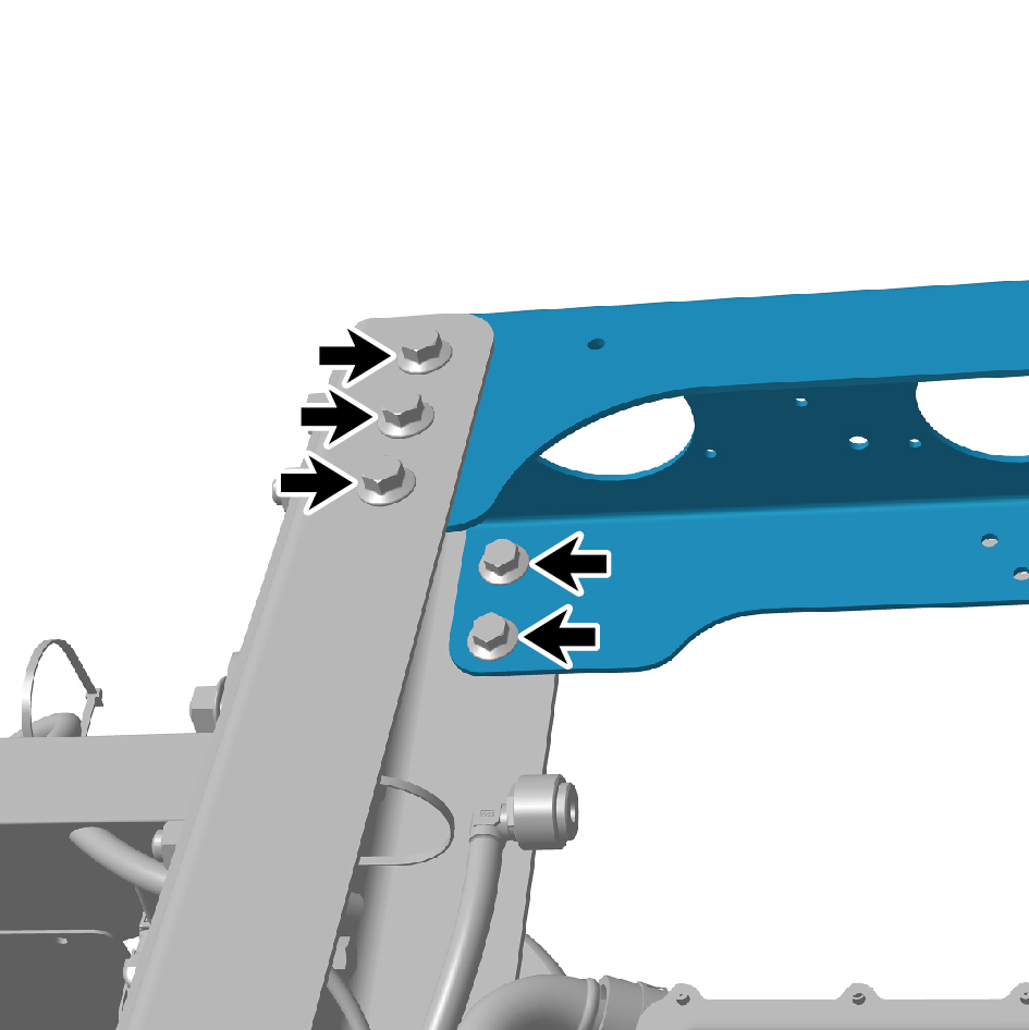
12
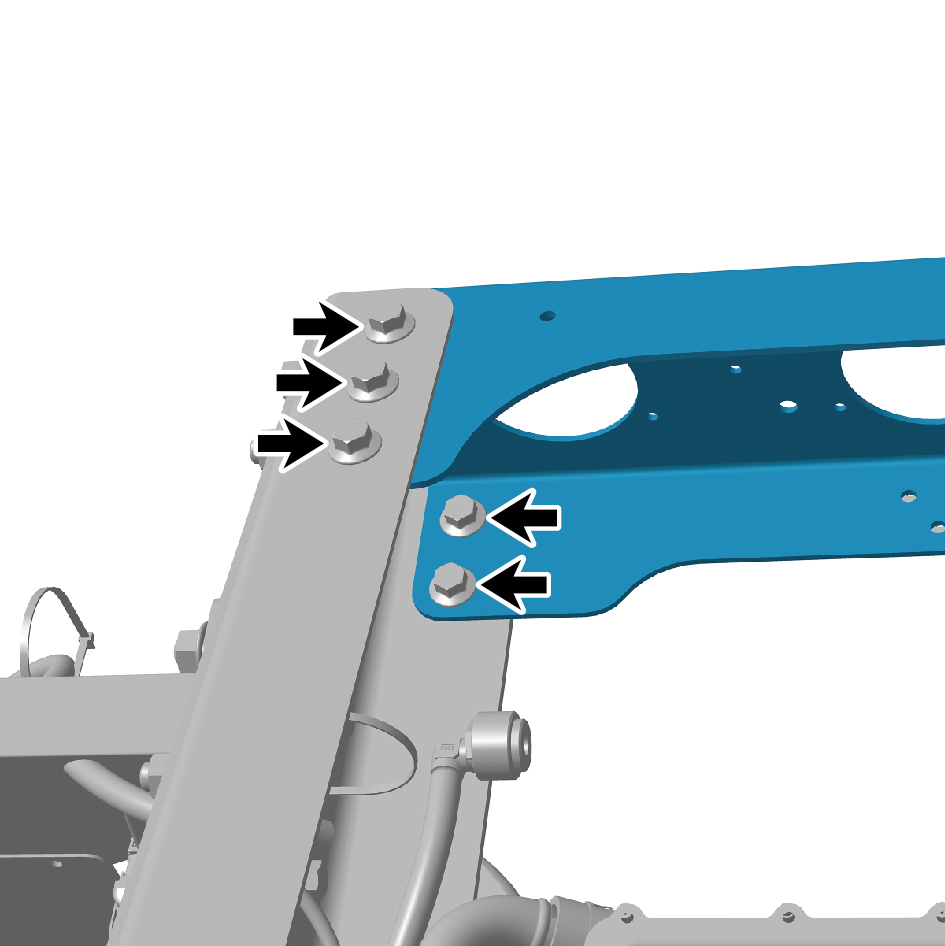
Remove 10 fixing bolts and nuts of the tail cross beam.
13
Remove the tail cross beam.
Installation Procedures
1
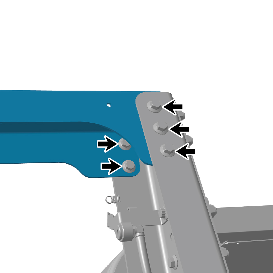
Move the tail cross beam to the mounting position.
2
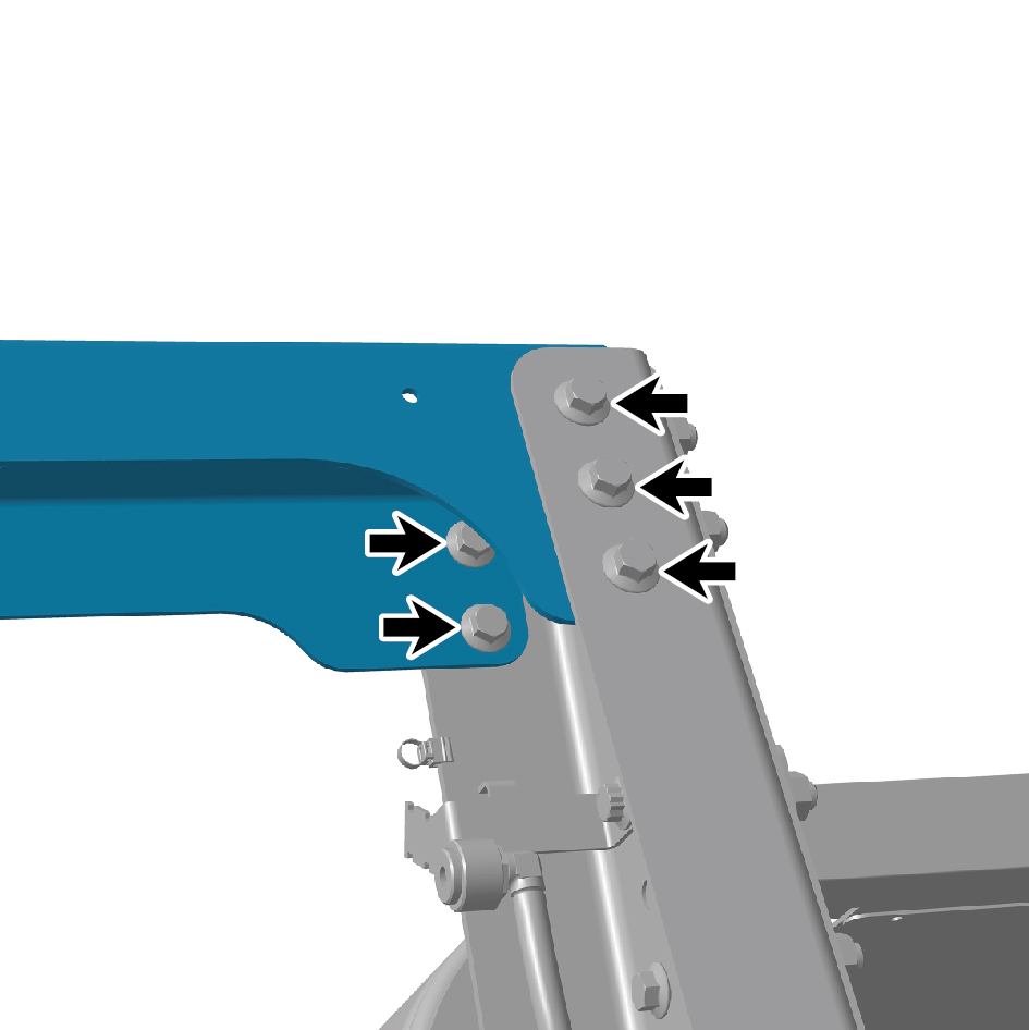
Install 10 fixing bolts and nuts of the tail cross beam.
3
Install the rear retro-reflector.
4
Install the reversing lamp.
5
Install the right rear combination lamp.
6
Install the left rear combination lamp.
7
Install the rear license plate mounting plate assembly.
8
Install the license plate lamp.
9
Install the air reservoir assembly (rear).
10
Connect the battery negative cable.
11
Close the front flip cover plate.
5
Close the door.
8.2.2.6 Replacement of Tubular Beam
Removal Procedures
1
Release air pressure from the brake system.
2
Open the door.
3
Open the front flip cover plate.
4
Disconnect the battery negative cable.
5
Perform power-off of high voltage system.
6
Jack the rear end of the vehicle.
7
Drain coolant from the power system.
8
Remove the drive wheel (rear left).
9
Remove the air reservoir bracket.
10
Removal the tail cross beam.
11
Remove the left tail cross beam reinforcement plate.
12
Remove the tail cross beam reinforcement plate
connecting plate.
13
Remove the air spring upper bracket 1.
14
Remove the rear air spring assembly - 260 (rear left).
15
Remove the height adjustment device assembly (left).
16
Remove the limit buffer assembly.
17
Remove the limit buffer assembly bracket.
18
Remove the shock absorber assembly (rear).
19
Remove the shock absorber bracket.
20
Remove the air spring upper bracket 3 (left rear).
21
Remove the rear air spring assembly - 280 (rear left).
22
Remove the longitudinal thrust rod assembly.
23
Remove the thrust bar bracket (left).
24
Remove the rear spring U-bolt.
25
Remove the balance beam (left).
26
Remove the airbag solenoid valve assembly (rear).
27
Remove the parking solenoid valve assembly.
28
Remove the drive wheel (rear right).
29
Remove the right tail cross beam reinforcement plate.
30
Remove the air spring upper bracket 2.
31
Remove the rear air spring assembly - 260 (rear right).
32
Remove the height adjustment device assembly (right).
33
Remove the air spring upper bracket 4 (right rear).
34
Remove the rear air spring assembly - 280 (rear right).
35
Remove the thrust bar bracket (right).
36
Remove the balance beam (right).
37
Remove the dual channel module assembly.
38
Remove the X-shaped control arm assembly (rear).
39
Remove the E-Axle Device - rear axle.
40
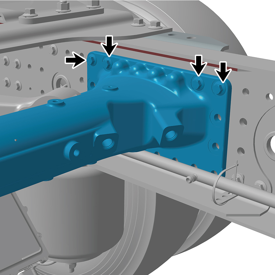
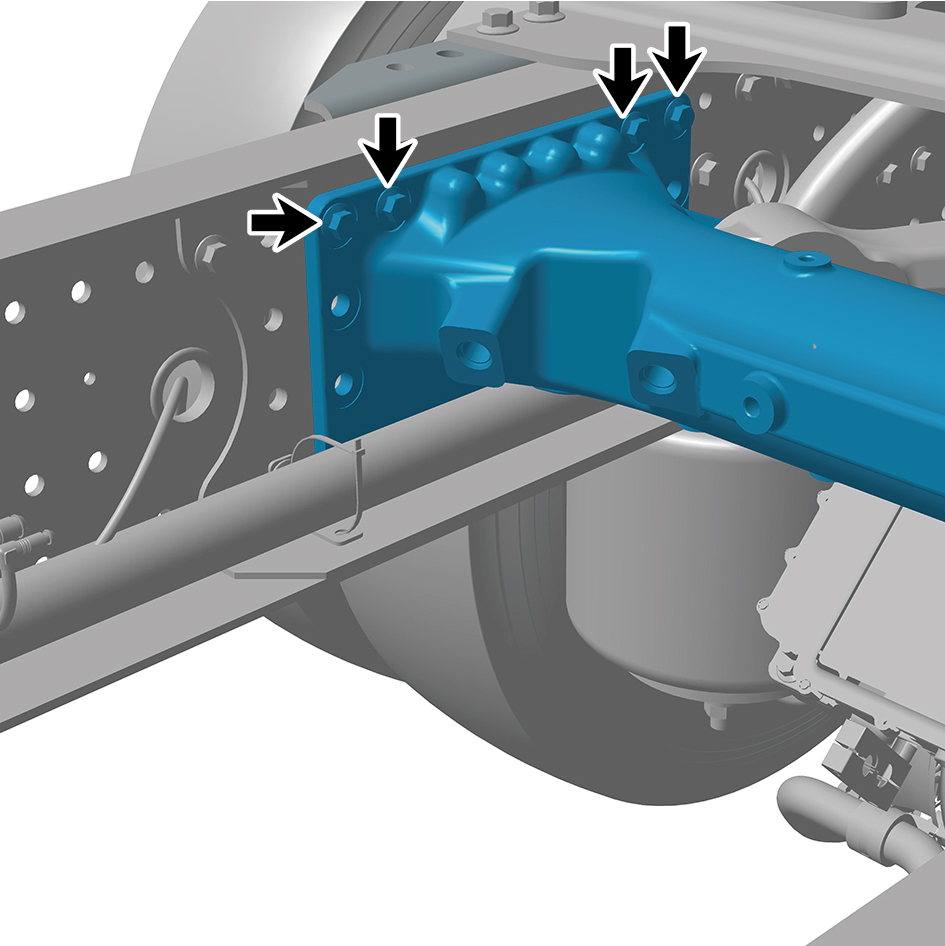
Remove 8 fixing bolts and nuts of the tubular beam.
41
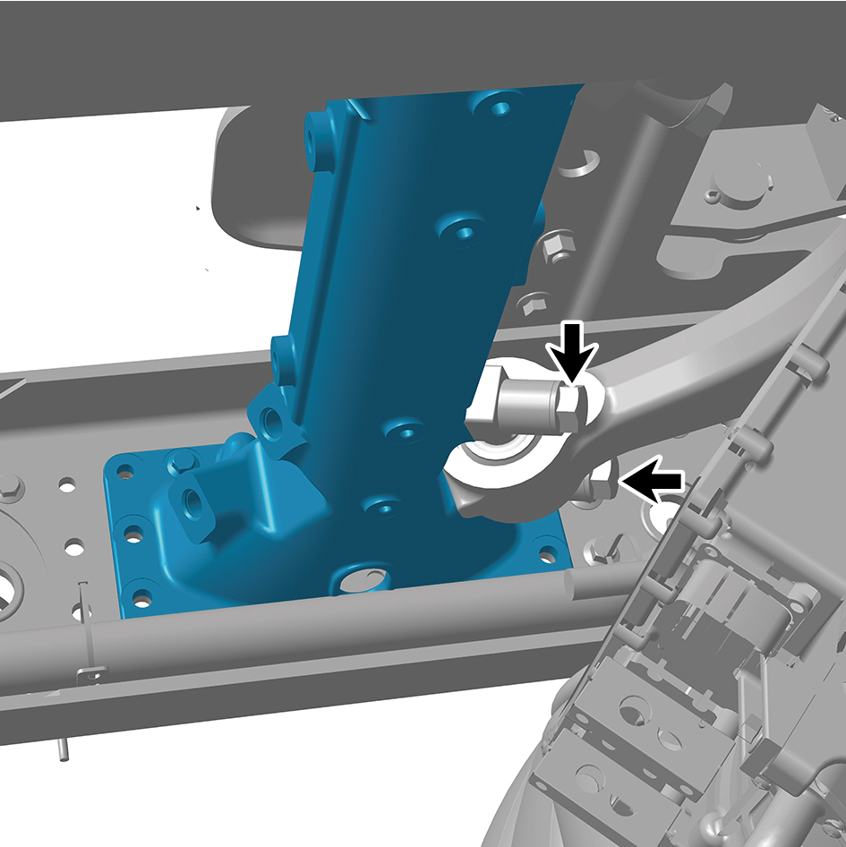
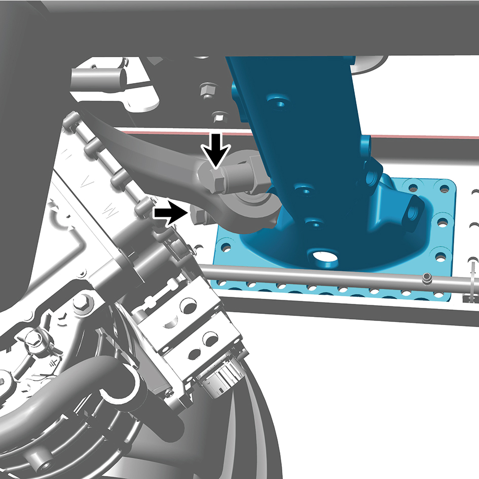
Remove 4 fixing bolts of the tubular beam.
42
Remove the tubular beam.
Installation Procedures
1
Move the tubular beam to the mounting position.
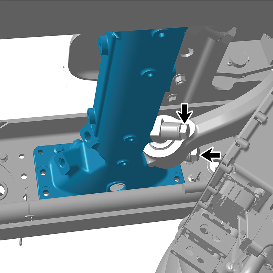
2
Install 4 fixing bolts of the tubular beam.
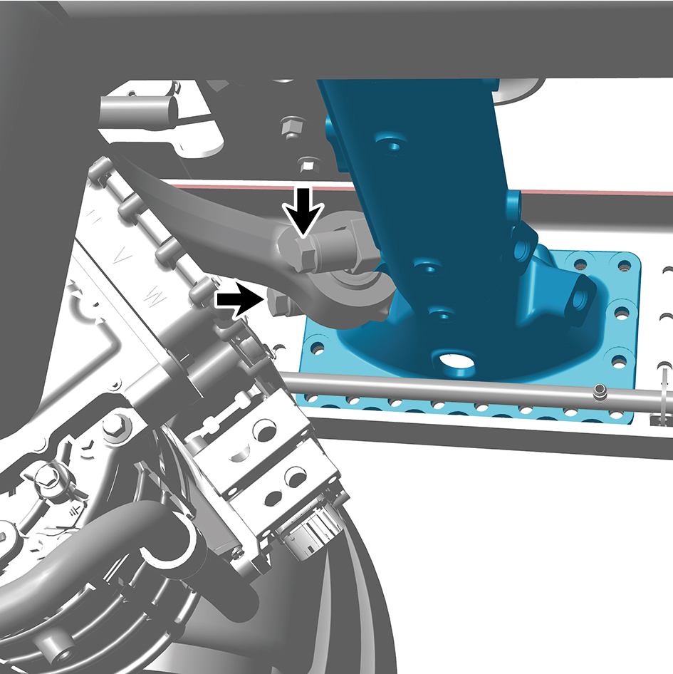
Torque: 516 +/- 37 (ft lbs)
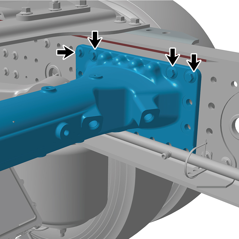
3
Install 8 fixing bolts and nuts of the tubular beam.
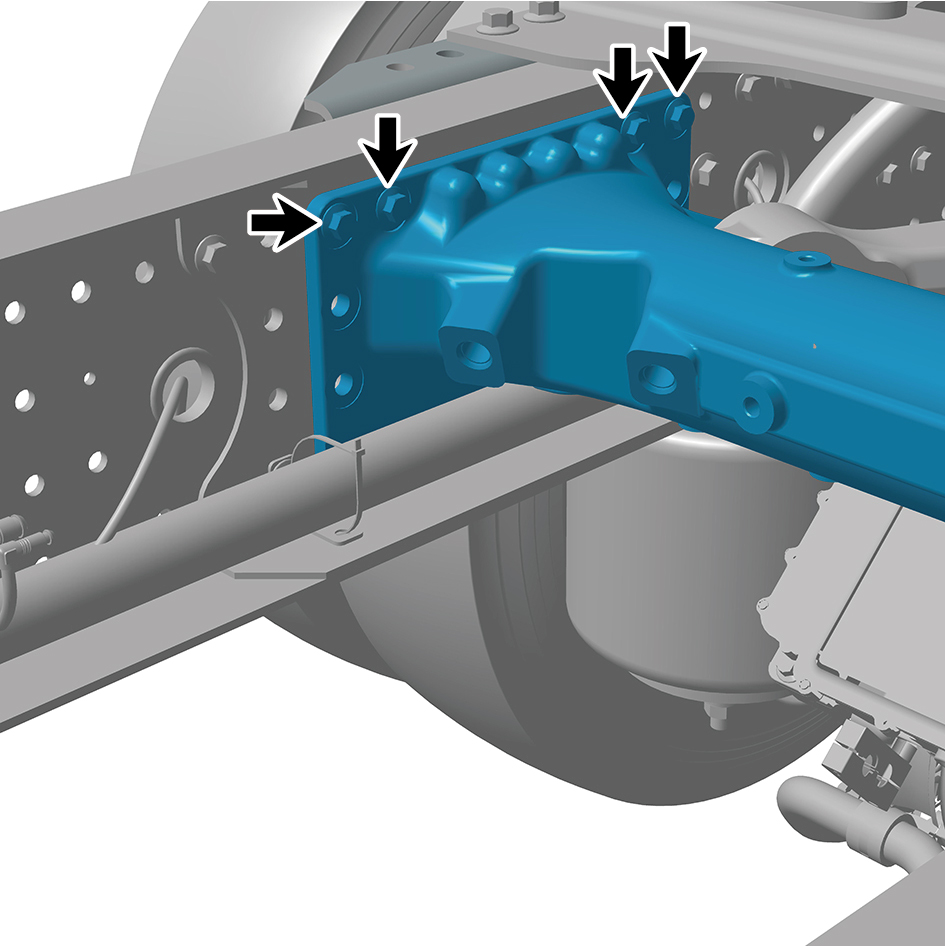
Torque: 155 +/- 14.75 (ft lbs)
4
Install the E-Axle Device - rear axle.
5
Install the X-shaped control arm assembly (rear).
6
Install the dual channel module assembly.
7
Install the balance beam (right).
8
Install the thrust bar bracket (right).
9
Install the rear air spring assembly - 280 (rear right).
10
Install the air spring upper bracket 4 (right rear).
11
Install the height adjustment device assembly (right).
12
Install the rear air spring assembly - 260 (rear right).
13
Install the air spring upper bracket 2.
14
Install the right tail cross beam reinforcement plate.
15
Install the drive wheel (rear right).
16
Install the parking solenoid valve assembly.
17
Install the airbag solenoid valve assembly (rear).
18
Install the balance beam (left).
19
Install the rear spring U-bolt.
20
Install the thrust bar bracket (left).
21
Install the longitudinal thrust rod assembly.
22
Install the rear air spring assembly - 280 (rear left).
23
Install the air spring upper bracket 3 (left rear).
24
Install the shock absorber bracket.
25
Install the shock absorber assembly (rear).
26
Install the limit buffer assembly bracket.
27
Install the limit buffer assembly.
28
Install the height adjustment device assembly (left).
29
Install the rear air spring assembly - 260 (rear left).
30
Install the air spring upper bracket 1.
31
Install the tail cross beam reinforcement plate connecting
plate.
32
Install the left tail cross beam reinforcement plate.
33
Install the tail cross beam.
34
Install the air reservoir bracket.
35
Install the drive wheel (rear left).
36
Fill coolant in the power system.
37
Lower the rear end of the vehicle.
38
Perform power-on of the high voltage system.
39
Connect the battery negative cable.
40
Close the front flip cover plate.
41
Close the door.