← Back to Contents
7 Automotive Electrical Appliances / 7.15 Information and Communication Device | PDF pages 1752-1801
7.15 Information and Communication Device
7.15 Information and Communication Device
7.15 Information and Communication
Device
7.15.1 Description and Operation
7.15.1.1 Description and Operation
The relevant communication devices between the vehicle and
the outside are as follows:
1. TGW functions: It serves as the on-board
terminal , It serves as the central gateway for the vehicle,
implements the CAN signal routing function at the vehicle end
, and provides an OBD diagnostic interface;
2.VTDR:The primary function of a digital tachograph is to
continuously monitor and store vehicle operational data and
driver activities, including speed, mileage, time, driver
identification, events, and faults, to meet the compliance
requirements of EU regulations (such as EEC 3821/85)
7.15.2 Specifications
7.15.2.1 Fastener Specifications
Range Of Torque
Fastener Specifications
Specifications
Foot Pounds of Torque (ft lbs)
The fixing bolt connecting the driving
recorder bracket to the lower left
(6.5 +/- .75) ft lbs
M6
instrument panel controller bracket
The fixing bolts connecting the T
(6.5 +/- .75) ft lbs
M6
gateway and the T gateway bracket
The fixing bolt connecting the lower left
dashboard controller bracket to the T
(6.5 +/- .75) ft lbs
M6
gateway bracket
The fixing bolts connecting the T
(6.5 +/- .75) ft lbs
M6
gateway and the T gateway bracket
7.15.3 Decomposition Diagram
7.15.3.1 Decomposition Diagram
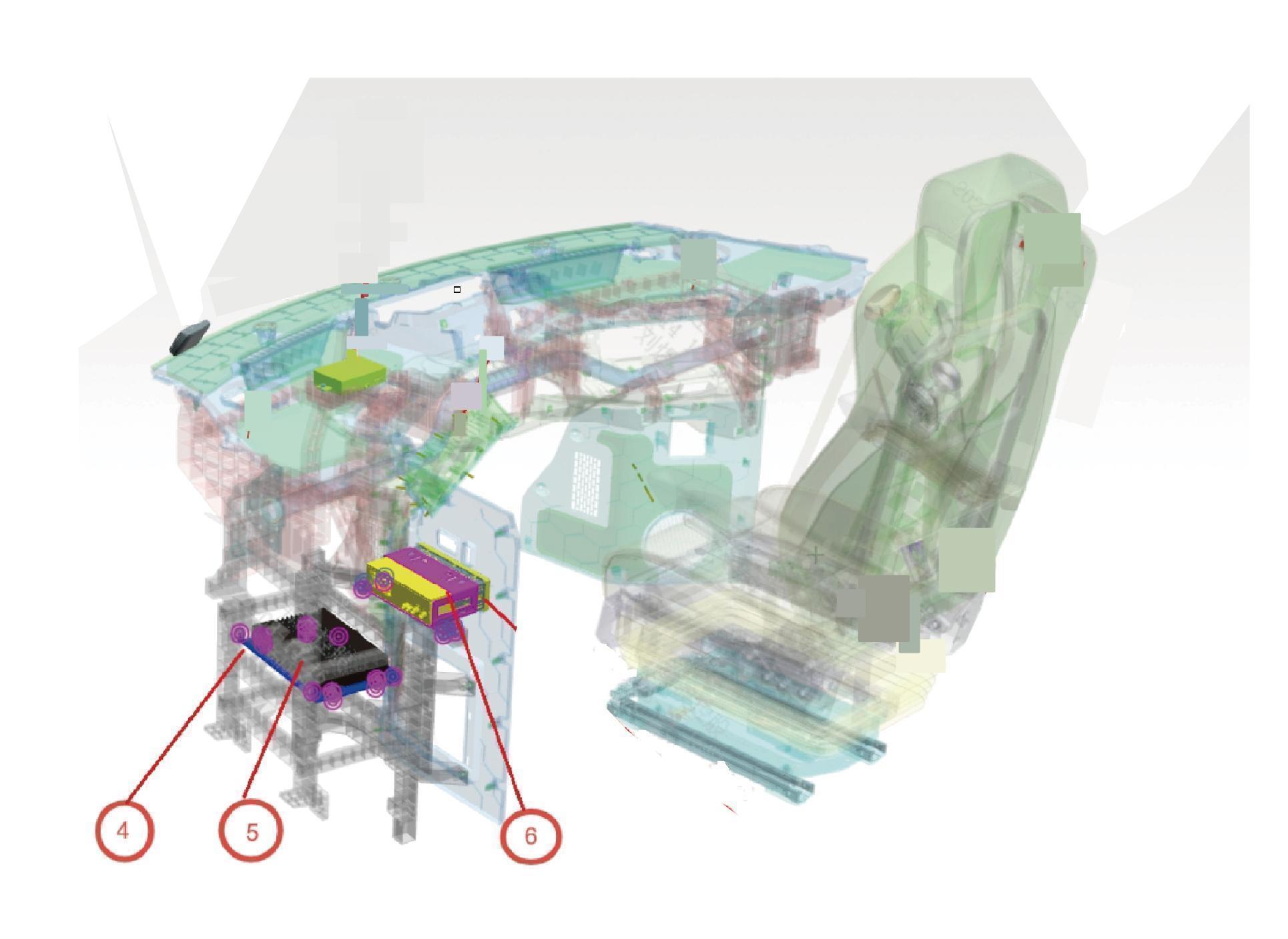
5.
4.
Tbox-Gw
Tbox-Gw Bracke
6.
Vehicle Travelling Data Recorder Bracket
7.15.4 System Schematic Diagram
7.15.4.1 Electrical Schematic Diagram
8
7.15.5 Diagnostic Information and Steps
7.15.5.1 Diagnostic Description
Before diagnosing faults in information communication devices, refer to Description And OperationUnderstanding and
familiarizing oneself with the working principle of information and communication devices before starting system diagnosis can
help determine the correct fault diagnosis steps in the event of a malfunction, and more importantly, it can help determine the
situation described by the customer belongs to normal operation. Any fault diagnosis of information and communication devices
should start with routine inspection, guiding maintenance personnel to take the next logical step for fault diagnosis.
Understanding and correctly using the diagnostic process can shorten the diagnosis time and avoid misjudgment of faulty parts.
7.15.5.2 Routine Inspection
• Check for aftermarket devices that may affect the operation of the information and communication device system, ensuring that
these devices do not affect the operation of the information and communication device system.
• Check system components that are easily accessible or visible to ensure that there is no obvious damage or potential
malfunction.
7.15.5.3 Fault Symptom Table
Symptom
Suspected Faulty Project
Measures
Update the diagnostic tool to the latest
1.The diagnostic tool version is too low
version.
Refer to OBD Power Supply Circuit
2.OBD power supply circuit fault
The diagnostic tool cannot
Fault
communicate with the vehicle
3. OBD CAN communication harness
Check the OBD CAN communication
malfunction
harness.
4. OBD Ethernet harness malfunction
Check the OBD Ethernet harness.
7.15.5.4 DTC Confirmation
1. Connect the diagnostic tool to the diagnostic interface, read and record the DTC, and then clear the DTC.
2. Run the vehicle again.
3. Read the fault code of the control system again to confirm if there is any fault code output from the system.
– Yes:Diagnose based on the output fault code.
– No:Perform intermittent fault check, refer to Inspection Of Intermittent Faults
7.15.5.5 List Of Diagnostic Trouble Codes (DTC)
Fault Description
Exclusion Method
Fault Code
High battery voltage
B111717
Refer to GW Power Fault
Low Battery Voltage
B111716
Lost Communication With CMS_L
U018787
Lost Communication With BDCU
U014087
communication with BDCU
Lost Communication With SJB_UP
U01A087
Refer to GW Communication Fault
U019987
Lost Communication With DCM
U014187
Lost Communication With AVAS
Lost Communication With SJB_UN
U01A187
Lost Communication With TPMS_F
U012787
Fault Description
Exclusion Method
Fault Code
U016487
Lost Communication With A/C
U015687
Lost Communication With CDCU
U015787
Lost Communication With CAMF
U026487
Lost Communication With USS
Lost Communication With MMWR_L
U026687
Lost Communication With MMWR_R
U026887
U012287
Lost Communication With VDC
U015A87
Lost Communication With FCU1
U015B87
Lost Communication With FCU2
U015C87
Lost Communication With HCU
U012187
Lost Communication With EBS
U013287
Lost Communication With ECAS
U012887
Lost Communication With EPB
U007388
CANFD1 BusOff
U007488
CANFD2 BusOff
U007588
CANFD3 BusOff
U007688
CANFD4 BusOff
U007788
CANFD5 BusOff
U007888
CANFD6 BusOff
U007988
CANFD7 BusOff
U007A88
CAN8 BusOff
U007B88
CANFD9 BusOff
U008088
CANFD10 BusOff
CANFD3 network limp home
U220200
CANFD4 network limp home
U220300
CANFD5 network limp home
U220400
CANFD6 network limp home
U220900
CANFD7 network limp home
U220500
CANFD10 network limp home
U220800
The Ethernet MDIO chip is abnormal
U238208
RTC chip error
B100000
MCU temperature is too high
B100001
Refer to GW Internal Fault
CPU temperature is too high
B100002
Backup battery not connected
B100004
End of backup battery life
B100005
BDC Ethernet T1 port connection
U100001
abnormality
Refer to GW Ethernet Fault
U100002
CDC Ethernet link failure
U100003
ADC Ethernet link failure
Fault Description
Exclusion Method
Fault Code
U100004
BDC Ethernet insufficient SQI
U100005
CDC Ethernet insufficient SQI
U100006
ADC Ethernet insufficient SQI
U100007
BDC Ethernet CRC error
U100008
CDC Ethernet CRC error
U100009
ADC Ethernet CRC error
Gateway certificate exception
U10000A
Refer to GW Certificate Abnormality
Gateway certificate application failed
U10000B
Root certificate exception
U10000C
TBOX
Fault Description
Exclusion Method
Fault Code
U019887
Lost Communication With GW
Refer to TBOX Communication Fault
U015687
Lost Communication With CDCU
Safety Chip Failure
B10FF96
Refer to TBOX Internal Fault
B10FE96
CODEC Module Failure
B10FA11
5G Antenna Shorted To The Ground
5G Antenna Open Circuit
Refer to Combination Antenna Fault
B10FA13
B10F996
5G Module Failure
Gateway certificate exception
U10000A
Refer to TBOX Certificate Abnormality
Gateway certificate application failed
U10000B
Root certificate exception
U10000C
B10FB00
No SIM Card
Please reinsert the SIM card
7.15.5.6 GW Power Fault
1. DTC Monitoring Logic
Description
DTC Trigger Conditions
Faulty Part
DTC Code
1. Main battery
Voltage measured > 32V for 5000ms(Deviation not
High battery voltage
B111717
2. Low voltage
exceeding 1000ms)
charging system
Voltage measured < 16V for 5000ms(Deviation not
3. Wiring harness
Low Battery Voltage
B111716
exceeding 1000ms)
4.T-Gateway
2.Circuit Diagram
Smart Junction Box - Chassis
Battery
C2-H
C1-1
C4-20
C5-D
KL15 Power
supply 3 G5D
KL15 Power
supply 1 G01
T-gateway -B+ O420
T-GW-B+ G2H
KL15-3 G5Da
KL15-1 G01a
1
3
I7_C_B
I7_C_B
4
I7_C_B
2
I7_C_B
1
3
I7_B_C
I7_B_C
4
I7_B_C
2
I7_B_C
KL15-1
KL15-3
G5Da
G01a
B1+ G2H
B2+ O420
KL15+1
KL15+2
G01m
G5Dd
B77-3
B77-2
B77-1
B77-15
T-gateway A/B
B76-13
B76-27
B77-4
B77-9
B77-21
Ground Z04
Ground Z04
Ground Z04
Ground Z04
Ground Z04
Ground Z04
G26
T-gateway A/B
120Ω
120Ω
B76-17
B76-3
B76-2
B77-13
B76-16
B77-14
Ground Z04
Ground Z04
5G diversity antenna 1
5G diversity antenna 2
5G diversity antenna 3
GWCANFD1_H TH01
GWCANFD1_L TL01
ADSCAN1_H TH02
5G antenna
ADSCAN1_L TL02
25
I_B_RR
24
I_B_RR
14
I_B_BU
10
I_B_BU
25
I_RR_B
24
I_RR_B
14
I_BU_B
10
I_BU_B
GPS/ positioning antenna
Ground Z04
4G antenna
GWCANFD1_H TH01
GWCANFD1_L TL01
ADSCAN1_H TH02b
ADSCAN1_L TL02b
Tachograph
ADSCAN1
G26
GWCANFD1
3. Diagnostic Steps
Step 1:DTC confirmation. Refer to DTC Confirmation
Step 2:Routine inspection. Refer to Routine Inspection
Step 3:Check if there are any other module power fault codes besides GW?
Check the main battery. Refer to Inspection Of The Main Battery
– Yes:
Check the low-voltage charging system. Refer to DCDC1 Low-voltage Charging System Fault
Next step
– No:
Step 4:Check the T-gateway power and grounding harness.
Step 5:T-Gateway rewrites configuration codes, software reloads, upgrades.
Step 6:Replace the T-gateway. Refer to Replacement Of T Gateway
Step 7:Clear and confirm DTC.
7.15.5.7 GW Communication Fault
1. DTC Monitoring Logic
Description
DTC Trigger Conditions
Faulty Part
DTC Code
1.Message 0x18FF0351 timeout for 10cycle(Cycle = 50
Lost Communication
ms)
U018787
With CMS_L
2.battery in normal voltage(16v-32v)
Lost Communication
1.Message 0x0CFDCC21 timeout for 10cycle(Cycle =
With BDCU
100 ms)
U014087
communication with
2.battery in normal voltage(16v-32v)
BDCU
1.Message 0x18FF3354 timeout for 10cycle(Cycle =
Lost Communication
100 ms)
U01A087
With SJB_UP
2.battery in normal voltage(16v-32v)
1.Message 0x18FDA54F timeout for 10cycle(Cycle =
Lost Communication
100 ms)
U019987
With DCM
2.battery in normal voltage(16v-32v)
1.Message 0x18FF0E57 timeout for 10cycle(Cycle =
1. Wiring harness
Lost Communication
500 ms)
U014187
2. T-Gateway
With AVAS
2.battery in normal voltage(16v-32v)
1.Message 0x18FF2359 timeout for 10cycle(Cycle =
Lost Communication
500 ms)
U01A187
With SJB_UN
2.battery in normal voltage(16v-32v)
1.Message 0x18FEF433 timeout for 10cycle(Cycle =
Lost Communication
500 ms)
U012787
With TPMS_F
2.battery in normal voltage(18v-32v)
1.Message 0x18FF0B19 timeout for 10cycle(Cycle =
Lost Communication
100 ms)
U016487
With A/C
2.battery in normal voltage(18v-32v)
1.Message 0x18FF0841 timeout for 10cycle(Cycle =
Lost Communication
1000 ms)
U015687
With CDCU
2.battery in normal voltage(18v-32v)
Description
DTC Trigger Conditions
Faulty Part
DTC Code
1.Message 0x18FF3531 timeout for 10cycle(Cycle =
Lost Communication
100 ms)
U015787
With CAMF
2.battery in normal voltage(18v-32v)
1.Message 0x18FF5C5F timeout for 10cycle(Cycle =
Lost Communication
100 ms)
U026487
With USS
2.battery in normal voltage(18v-32v)
1.Message 0x18FF4361 timeout for 10cycle(Cycle =
Lost Communication
100 ms)
U026687
With MMWR_L
2.battery in normal voltage(18v-32v)
1.Message 0x18FF4263 timeout for 10cycle(Cycle =
Lost Communication
100 ms)
U026887
With MMWR_R
2.battery in normal voltage(18v-32v)
1.Message 0x18FEF100 timeout for 10cycle(Cycle =
Lost Communication
100 ms)
U012287
With VDC
2.battery in normal voltage(18v-32v)
1.Message 0x18102465 timeout for 10cycle(Cycle =
Lost Communication
100 ms)
U015A87
With FCU1
2.battery in normal voltage(18v-32v)
1.Message 0x181024A5 timeout for 10cycle(Cycle =
Lost Communication
100 ms)
U015B87
With FCU2
2.battery in normal voltage(18v-32v)
1.Message 0x18f30189 timeout for 10cycle(Cycle = 100
Lost Communication
ms)
U015C87
With HCU
2.battery in normal voltage(18v-32v)
1.Message 0x18F0010B timeout for 10cycle(Cycle =
Lost Communication
100 ms)
U012187
With EBS
2.battery in normal voltage(18v-32v)
1.Message 0x18FEEA2F timeout for 10cycle(Cycle =
Lost Communication
100 ms)
U013287
With ECAS
2.battery in normal voltage(18v-32v)
1.Message 0x18FE1250 timeout for 10cycle(Cycle =
Lost Communication
100 ms)
U012887
With EPB
2.battery in normal voltage(18v-32v)
U007388
CANFD1 BusOff
CANFD1 bus communication failure
U007488
CANFD2 BusOff
CANFD2 bus communication failure
U007588
CANFD3 BusOff
CANFD3 bus communication failure
U007688
CANFD4 BusOff
CANFD4 bus communication failure
U007788
CANFD5 BusOff
CANFD5 bus communication failure
U007888
CANFD6 BusOff
CANFD6 bus communication failure
U007988
CANFD7 BusOff
CANFD7 bus communication failure
U007A88
CAN8 BusOff
CANFD8 bus communication failure
Description
DTC Trigger Conditions
Faulty Part
DTC Code
U007B88
CANFD9 BusOff
CANFD9 bus communication failure
U008088
CANFD10 BusOff
CANFD10 bus communication failure
CANFD3 network limp
CANFD3 NM in limp home state
U220200
home
CANFD4 network limp
CANFD4 NM in limp home state
U220300
home
CANFD5 network limp
CANFD5 NM in limp home state
U220400
home
CANFD6 network limp
CANFD6 NM in limp home state
U220900
home
CANFD7 network limp
CANFD7 NM in limp home state
U220500
home
CANFD10 network
CANFD10 NM in limp home state
U220800
limp home
2.Circuit Diagram
T-gateway A/B
120Ω
120Ω
B76-17
B76-3
B76-2
B77-13
B76-16
B77-14
Ground Z04
Ground Z04
5G diversity antenna 1
5G diversity antenna 2
5G diversity antenna 3
GWCANFD1_H TH01
GWCANFD1_L TL01
ADSCAN1_H TH02
5G antenna
ADSCAN1_L TL02
25
I_B_RR
24
I_B_RR
14
I_B_BU
10
I_B_BU
Combination antenna
25
I_RR_B
24
I_RR_B
14
I_BU_B
10
I_BU_B
GPS/ positioning antenna
Ground Z04
4G antenna
GWCANFD1_H TH01
GWCANFD1_L TL01
ADSCAN1_H TH02b
ADSCAN1_L TL02b
Tachograph
ADSCAN1
G26
GWCANFD1
T-gateway A
120Ω
120Ω
120Ω
B76-18
B76-20
B76-6
B76-4
B76-19
B76-5
B76-5
GWCANFD3_H TH03
GWCANFD5_H TH05
GWCANFD4_H TH04
GWCANFD3_L TL03
GWCANFD5_L TL05
GWCANFD4_L TL04
9
I2_B_IP
10
I2_B_IP
9
I2_IP_B
10
I2_IP_B
GWCANFD4_H TH04
GWCANFD4_L TL04
GWCANFD4
GWCANFD5
GWCANFD3
T-gateway A
120Ω
120Ω
120Ω
B76-9
B76-23
B76-22
B76-8
B76-10
B76-7
B76-21
B76-24
Chassis CAN8-H TH08
Chassis CAN8-L TL08
GWCANFD7_H TH07
GWCANFD9_H TH09
GWCANFD7_L TL07
GWCANFD9_L TL09
Intelligent driving
Intelligent driving
CAN-H TH06
CAN-L TL06
27
26
I8_B_C
I8_B_C
25
5
I8_B_C
I2_B_IP
35
36
I8_B_C
I8_B_C
34
16
I8_B_C
I8_B_IP
27
26
I8_C_B
I8_C_B
25
5
I8_C_B
I8_IP_B
35
36
I8_C_B
I8_C_B
34
16
I8_C_B
I8_IP_B
Chassis CAN8-H
GWCANFD9_H
Chassis CAN8-L
GWCANFD9_L
Intelligent driving CAN-H TH06
Intelligent driving CAN-L TL06
TH09
TH08
TL09
TL08
GWCANFD7_H TH07
GWCANFD7_L TL07
GWCANFD9_H TH09a
Chassis CAN8-H TH08
Chassis CAN8-L TL08
GWCANFD8_L TL07a
Chassis CAN8
GWCANFD7
GWCANFD9
Intelligent driving CAN
Chassis CAN8-H TH08f
Chassis CAN8-L TL08f
GWCANFD9-H TH09
GWCANFD9-L TL09
IP07-1
IP07-2
C20-1
C20-2
CAN resistance A -120Ω
CAN resistance -120Ω
3. Diagnostic Steps
Step 1:DTC confirmation. Refer to DTC Confirmation
Step 2:Routine inspection. Refer to Routine Inspection
Step 3:Check the CANFD1 bus communication harness. Refer to Inspection Of CANFD1 Bus Network Integrity
Step 4:Check the CANFD3 bus communication harness. Refer to Inspection Of CANFD3 Bus Network Integrity
Step 5:Check the CANFD4 bus communication harness. Refer to Inspection Of CANFD4 Bus Network Integrity
Step 6:Check the CANFD5 bus communication harness. Refer to Inspection Of CANFD5 Bus Network Integrity
Step 7:Check the CANFD6 bus communication harness. Refer to Inspection Of CANFD6 Bus Network Integrity
Step 8:Check the CANFD7 bus communication harness. Refer to Inspection Of CANFD7 Bus Network Integrity
Step 9:Check the CAN8 bus communication harness. Refer to Inspection Of CAN8 Bus Network Integrity
Step 10:Check the CANFD9 bus communication harness. Refer to Inspection Of CANFD9 Bus Network Integrity
Step 11:T-Gateway rewrites configuration codes, software reloads, upgrades.
Step 12:Replace the T-gateway. Refer to Replacement Of T Gateway
Step 13:Clear and confirm DTC.
7.15.5.8 GW Internal Fault
1. DTC Monitoring Logic
Description
DTC Trigger Conditions
Faulty Part
DTC Code
The Ethernet MDIO
Unable to read SWITCH chip register
U238208
chip is abnormal
RTC chip error
B100000
Get RTC time error lasts 5s
MCU temperature is
Temperature measurement > 110℃for 5s
B100001
too high
1. T-Gateway
CPU temperature is
Temperature measurement > 110℃for 5s
B100002
too high
Backup battery not
Backup battery not connected for more than 5s
B100004
connected
End of backup battery
Backup battery life less than 10%
B100005
life
2. Diagnostic Steps
Step 1:DTC confirmation. Refer to DTC Confirmation
Step 2:Routine inspection. Refer to Routine Inspection
Step 3:T-Gateway rewrites configuration codes, software reloads, upgrades.
Step 4:Replace the T-gateway. Refer to Replacement Of T Gateway
Step 5:Clear and confirm DTC.
7.15.5.9 GW Ethernet Fault
1.DTC Monitoring Logic
Description
DTC Trigger Conditions
Faulty Part
DTC Code
If the current link status of the Ethernet port is not link-
BDC Ethernet T1 port
1. Wiring harness
Up, the counter increases by 1. If the current link status
connection
U100001
2. T-Gateway
is not link-Up for 10 consecutive times, a fault is
abnormality
reported
Description
DTC Trigger Conditions
Faulty Part
DTC Code
If the current link status of the Ethernet port is not link-
Up, the counter increases by 1. If the current link status
CDC Ethernet link
U100002
is not link-Up for 10 consecutive times, a fault is
failure
reported
If the current link status of the Ethernet port is not link-
Up, the counter increases by 1. If the current link status
ADC Ethernet link
U100003
is not link-Up for 10 consecutive times, a fault is
failure
reported
BDC Ethernet
SQI below the threshold occurs 20 times within 60s
U100004
insufficient SQI
CDC Ethernet
SQI below the threshold occurs 20 times within 60s
U100005
insufficient SQI
ADC Ethernet
SQI below the threshold occurs 20 times within 60s
U100006
insufficient SQI
Read the Ethernet chip CRC value and report a fault if
BDC Ethernet CRC
U100007
there is a single CRC error
error
Read the Ethernet chip CRC value and report a fault if
CDC Ethernet CRC
U100008
there is a single CRC error
error
Read the Ethernet chip CRC value and report a fault if
ADC Ethernet CRC
U100009
there is a single CRC error
error
2. Circuit Diagram
Smart Junction
Smart Junction Box - Body
Box - Chassis
Battery
B12-1
B01-1
B09-4
Total body power
supply B+ L22
OBD Interface
Power B+ P304
Bluetooth &NFC Module
B+ P304b
T-GW-OBD Ethernet
B79-1
B79-3
B79-2
B79-4
Ethernet sends signals - TTN
Ethernet sends signal + TTP
37
I1_B_IP
Ethernet received
Ethernet received
signal + TRP
signal - TRN
37
I1_IP_B
Bluetooth &NFC Module
B+ P304b
6
I2_B_IP
3
I2_B_IP
17
I2_B_IP
2
I2_B_IP
6
I2_IP_B
3
I2_IP_B
17
I2_IP_B
2
I2_IP_B
Ethernet received
Ethernet received
Ethernet sends
Ethernet sends
signals - TTN
signal + TRP
signal + TTP
signal - TRN
B+ P304a
IP08-16
IP08-12
IP08-3
IP08-11
IP08-13
OBD interface
3. Diagnostic Steps
Step 1:DTC Confirmation.Refer to DTC Confirmation
Step 2:Routine Inspection.Refer to Routine Inspection
Step 3:Check the T-gateway Ethernet harness.
Step 4:T-Gateway rewrites configuration codes, software reloads, upgrades.
Step 5:Replace the T-gateway. Refer to Replacement Of T Gateway
Step 6:Clear and confirm DTC.
7.15.5.11 TBOX Communication Fault
1. DTC Monitoring Logic
Description
DTC Trigger Conditions
Faulty Part
DTC Code
Lost Communication
No GW heartbeat received, lasting for 60 seconds
U019887
With GW
1. Wiring harness
2. T-Gateway
No USB channel communication heartbeat received
Lost Communication
U015687
from CDCU, lasting for 60 seconds
With CDCU
2.Circuit Diagram
T-gateway A/B
120Ω
120Ω
B76-17
B76-3
B76-2
B77-13
B76-16
B77-14
Ground Z04
Ground Z04
5G diversity antenna 1
5G diversity antenna 2
5G diversity antenna 3
GWCANFD1_H TH01
GWCANFD1_L TL01
ADSCAN1_H TH02
5G antenna
ADSCAN1_L TL02
25
I_B_RR
24
I_B_RR
14
I_B_BU
10
I_B_BU
Combination antenna
25
I_RR_B
24
I_RR_B
14
I_BU_B
10
I_BU_B
GPS/ positioning antenna
Ground Z04
4G antenna
GWCANFD1_H TH01
GWCANFD1_L TL01
ADSCAN1_H TH02b
ADSCAN1_L TL02b
Tachograph
ADSCAN1
G26
GWCANFD1
T-gateway A
120Ω
120Ω
120Ω
B76-18
B76-20
B76-6
B76-4
B76-19
B76-5
B76-5
GWCANFD3_H TH03
GWCANFD5_H TH05
GWCANFD4_H TH04
GWCANFD3_L TL03
GWCANFD5_L TL05
GWCANFD4_L TL04
9
I2_B_IP
10
I2_B_IP
9
I2_IP_B
10
I2_IP_B
GWCANFD4_H TH04
GWCANFD4_L TL04
GWCANFD4
GWCANFD5
GWCANFD3
T-gateway A
120Ω
120Ω
120Ω
B76-9
B76-23
B76-22
B76-8
B76-10
B76-7
B76-21
B76-24
Chassis CAN8-H TH08
Chassis CAN8-L TL08
GWCANFD7_H TH07
GWCANFD9_H TH09
GWCANFD7_L TL07
GWCANFD9_L TL09
Intelligent driving
Intelligent driving
CAN-H TH06
CAN-L TL06
27
26
I8_B_C
I8_B_C
25
5
I8_B_C
I2_B_IP
35
36
I8_B_C
I8_B_C
34
16
I8_B_C
I8_B_IP
27
26
I8_C_B
I8_C_B
25
5
I8_C_B
I8_IP_B
35
36
I8_C_B
I8_C_B
34
16
I8_C_B
I8_IP_B
Chassis CAN8-H
GWCANFD9_H
Chassis CAN8-L
GWCANFD9_L
Intelligent driving CAN-H TH06
Intelligent driving CAN-L TL06
TH09
TH08
TL09
TL08
GWCANFD7_H TH07
GWCANFD7_L TL07
GWCANFD9_H TH09a
Chassis CAN8-H TH08
Chassis CAN8-L TL08
GWCANFD8_L TL07a
Chassis CAN8
GWCANFD7
GWCANFD9
Intelligent driving CAN
Chassis CAN8-H TH08f
Chassis CAN8-L TL08f
GWCANFD9-H TH09
GWCANFD9-L TL09
IP07-1
IP07-2
C20-1
C20-2
CAN resistance A -120Ω
CAN resistance -120Ω
3. Diagnostic Steps
Step 1:DTC confirmation. Refer to DTC Confirmation
Step 2:Routine inspection. Refer to Routine Inspection
Step 3:Check the CANFD1 bus communication harness. Refer to Inspection Of CANFD1 Bus Network Integrity
Step 4:Check the CANFD3 bus communication harness. Refer to Inspection Of CANFD3 Bus Network Integrity
Step 5:Check the CANFD4 bus communication harness. Refer to Inspection of CANFD4 bus network integrity
Step 6:Check the CANFD5 bus communication harness. Refer to Inspection of CANFD5 bus network integrity
Step 7:Check the CANFD6 bus communication harness. Refer to Inspection Of CANFD6 Bus Network Integrity
Step 8:Check the CANFD7 bus communication harness. Refer to Inspection Of CANFD7 Bus Network Integrity
Step 9:Check the CAN8 bus communication harness. Refer to Inspection Of CAN8 Bus Network Integrity
Step 10:Check the CANFD9 bus communication harness. Refer to Inspection Of CANFD9 Bus Network Integrity
Step 11:T-Gateway rewrites configuration codes, software reloads, upgrades.
Step 12:Replace the T-gateway. Refer to Replacement Of T Gateway
Step 13:Clear and confirm DTC.
7.15.5.12 TBOX Internal Fault
1. DTC Monitoring Logic
Description
DTC Trigger Conditions
Faulty Part
DTC Code
Safety Chip Failure
B10FF96
command timeout
1. T-Gateway
CODEC Module
codec Module initialization failed or Codec the module
B10FE96
Failure
cannot communicate
2. Diagnostic Steps
Step 1:DTC confirmation. Refer to DTC Confirmation
Step 2:Routine inspection. Refer to Routine Inspection
Step 3:T-Gateway rewrites configuration codes, software reloads, upgrades.
Step 4:Replace the T-gateway. Refer to Replacement Of T Gateway
Step 5:Clear and confirm DTC.
7.15.5.13 Combination Antenna Fault
1.Circuit Diagram
T-gateway A/B
120Ω
120Ω
B76-17
B76-3
B76-2
B77-13
B76-16
B77-14
Ground Z04
Ground Z04
5G diversity antenna 1
5G diversity antenna 2
5G diversity antenna 3
GWCANFD1_H TH01
GWCANFD1_L TL01
ADSCAN1_H TH02
5G antenna
ADSCAN1_L TL02
25
I_B_RR
24
I_B_RR
14
I_B_BU
10
I_B_BU
Combination antenna
25
I_RR_B
24
I_RR_B
14
I_BU_B
10
I_BU_B
GPS/ positioning antenna
Ground Z04
4G antenna
GWCANFD1_H TH01
GWCANFD1_L TL01
ADSCAN1_H TH02b
ADSCAN1_L TL02b
Tachograph
ADSCAN1
G26
GWCANFD1
2 . Diagnostic Steps
Step 1:DTC confirmation. Refer to DTC Confirmation
Step 2:Routine inspection. Refer to Routine Inspection
Step 3:Check the wiring harness between the T-gateway and the combination
antenna.
Step 4:Replace the combination antenna. Refer to Replacement of combination antenna
Step 5:T-Gateway rewrites configuration codes, software reloads, upgrades.
Step 6:Replace the T-gateway. Refer to Replacement Of T Gateway
Step 7:Clear and confirm DTC.
7.15.5.15 Inspection Of CAN8 Bus Network Integrity
Step 1
Check the terminal resistance of CAN8 bus.
A.
Perform vehicle power on operation.
B.
Do not disconnect the wiring harness connector. Use a
multimeter to measure each terminal according to the
following table:
Measuring Terminals
Standard Value
CAN8(H) and CAN8(L)
Resistance:55 - 63 Ω
C.
Confirm the measured values meet the standards.
Up to step 6.
Yes
Step 2
Check the CAN8 bus voltage.
A.
Perform vehicle power on operation.
B.
Do not disconnect the wiring harness connector. Use a
multimeter to measure each terminal according to the
following table:
Measuring Terminals
Standard Value
CAN8 (H) and vehicle
Voltage:2.5 - 3.5 V
grounding
CAN8 (L) and vehicle
Voltage:1.5 - 2.5 V
grounding
C.
Confirm the measured values meet the standards.
Up to step 6.
Yes
Step 3
Check the bus voltage of each module.
A.
Perform vehicle power on operation.
B.
Measure the bus voltage of each module in sequence
(do not disconnect the harness connectors).
Measuring Terminals
Standard Value
CAN8 (H) and vehicle
Voltage:2.5 - 3.5 V
grounding
CAN8 (L) and vehicle
Voltage:1.5 - 2.5 V
grounding
C.
Confirm the bus voltage of each module meets the
standard.
Up to step 6.
Yes
Step 4
Check the power grounding of the communication loss module.
A.
Check the power grounding of the communication loss
module.
B.
Confirm if the module power grounding is normal.
Repair or replace the wiring harness.
Yes
Step 5
Replace the communication loss module.
A.
Replace the communication loss module.
B.
Confirm if the system is functioning properly.
Yes
The system is functioning properly.
Step 6
Check the CAN8 bus harness.
A.
Perform vehicle power-off operation.
B.
Disconnect all module harness connectors on the CAN8
bus.
C.
Measure the CAN8 bus resistance between each
module and the T-gateway sequentially to see if it is
normal.
Standard resistance:less than 1 Ω
D.
Measure the ground resistance of CAN8 bus is normal.
Standard resistance:10K Ω or higher
E.
Perform vehicle power on operation.
F.
Measure the CAN8 bus is short circuited to the power
supply.
Standard voltage:0 V
G.
Confirm the measured values meet the standards.
Repair or replace the CAN8 bus.
Yes
Step 7
Disconnect the modules on the CAN8 bus in sequence and observe the bus communication voltage/resistance.
Disconnect the modules on the CAN8 bus in sequence and
observe the bus communication voltage/resistance returns
to normal. If it returns to normal, determine that the
disconnected module is faulty.
7.15.5.16 Inspection Of CANFD1 Bus Network Integrity
Step 1
Check the terminal resistance of CANFD1 bus.
A.
Perform vehicle power on operation.
B.
Do not disconnect the wiring harness connector. Use a
multimeter to measure each terminal according to the
following table:
Measuring Terminals
Standard Value
CANFD1(H) and
Resistance:55 - 63 Ω
CANFD1(L)
C.
Confirm the measured values meet the standards.
Up to step 6.
Yes
Step 2
Check the CANFD1 bus voltage.
A.
Perform vehicle power on operation.
B.
Do not disconnect the wiring harness connector. Use a
multimeter to measure each terminal according to the
following table:
Measuring Terminals
Standard Value
CANFD1 (H) and vehicle
Voltage:2.5 - 3.5 V
grounding
CANFD1 (L) and vehicle
Voltage:1.5 - 2.5 V
grounding
C.
Confirm the measured values meet the standards.
Up to step 6.
Yes
Step 3
Check the bus voltage of each module.
A.
Perform vehicle power on operation.
B.
Measure the bus voltage of each module in sequence
(do not disconnect the harness connectors).
Measuring Terminals
Standard Value
CANFD1 (H) and vehicle
Voltage:2.5 - 3.5 V
grounding
CANFD1 (L) and vehicle
Voltage:1.5 - 2.5 V
grounding
C.
Confirm the bus voltage of each module meets the
standard.
Up to step 6.
Yes
Step 4
Check the power grounding of the communication loss module.
A.
Check the power grounding of the communication loss
module.
B.
Confirm if the module power grounding is normal.
Repair or replace the wiring harness.
Yes
Step 5
Replace the communication loss module.
A.
Replace the communication loss module.
B.
Confirm if the system is functioning properly.
Yes
The system is functioning properly.
Step 6
Check the CANFD1 bus harness.
A.
Perform vehicle power-off operation.
B.
Disconnect all module harness connectors on the
CANFD1 bus.
C.
Measure the CANFD1 bus resistance between each
module and the T-gateway sequentially to see if it is
normal.
Standard resistance:less than 1 Ω
D.
Measure the ground resistance of CANFD1 bus is
normal.
Standard resistance:10K Ω or higher
E.
Perform vehicle power on operation.
F.
Measure the CANFD1 bus is short circuited to the power
supply.
Standard voltage:0 V
G.
Confirm the measured values meet the standards.
Repair or replace the CANFD1 bus.
Yes
Disconnect the modules on the CANFD1 bus in sequence and observe the bus communication voltage/
Step 7
resistance.
Disconnect the modules on the CANFD1 bus in sequence
and observe the bus communication voltage/resistance
returns to normal. If it returns to normal, determine that the
disconnected module is faulty.
7.15.5.17 Inspection Of CANFD3 Bus Network Integrity
Step 1
Check the CANFD3 bus terminal resistance.
A.
Perform vehicle power on operation.
B.
Do not disconnect the wiring harness connector. Use a
multimeter to measure each terminal according to the
following table:
Measuring Terminals
Standard Value
CANFD3(H) and
Resistance:55 - 63 Ω
CANFD3(L)
C.
Confirm the measured values meet the standards.
Up to step 6.
Yes
Step 2
Check the CANFD3 bus voltage.
A.
Perform vehicle power on operation.
B.
Do not disconnect the wiring harness connector. Use a
multimeter to measure each terminal according to the
following table:
Measuring Terminals
Standard Value
CANFD3 (H) and vehicle
Voltage:2.5 - 3.5 V
grounding
CANFD3 (L) and vehicle
Voltage:1.5 - 2.5 V
grounding
C.
Confirm the measured values meet the standards.
Up to step 6.
Yes
Step 3
Check the bus voltage of each module.
A.
Perform vehicle power on operation.
B.
Measure the bus voltage of each module in sequence
(do not disconnect the harness connectors).
Measuring Terminals
Standard Value
CANFD3 (H) and vehicle
Voltage:2.5 - 3.5 V
grounding
CANFD3 (L) and vehicle
Voltage:1.5 - 2.5 V
grounding
C.
Confirm the bus voltage of each module meets the
standard.
Up to step 6.
Yes
Step 4
Check the power grounding of the communication loss module.
A.
Check the power grounding of the communication loss
module.
B.
Confirm if the module power grounding is normal.
Repair or replace the wiring harness.
Yes
Step 5
Replace the communication loss module.
A.
Replace the communication loss module.
B.
Confirm if the system is functioning properly.
Yes
The system is functioning properly.
Step 6
Check the CANFD3 bus harness.
A.
Perform vehicle power-off operation.
B.
Disconnect all module harness connectors on the
CANFD3 bus.
C.
Measure the CANFD3 bus resistance between each
module and the T-gateway sequentially to see if it is
normal.
Standard resistance:less than 1 Ω
D.
Measure the ground resistance of CANFD3 bus is
normal.
Standard resistance:10K Ω or higher
E.
Perform vehicle power on operation.
F.
Measure the CANFD3 bus is short circuited to the power
supply.
Standard voltage:0 V
G.
Confirm the measured values meet the standards.
Repair or replace the CANFD3 bus.
Yes
Disconnect the modules on the CANFD3 bus in sequence and observe the bus communication voltage/
Step 7
resistance.
Disconnect the modules on the CANFD3 bus in sequence
and observe the bus communication voltage/resistance
returns to normal. If it returns to normal, determine that the
disconnected module is faulty.
7.15.5.18 Inspection Of CANFD4 Bus Network Integrity
Step 1
Check the CANFD4 bus terminal resistance.
A.
Perform vehicle power on operation.
B.
Do not disconnect the wiring harness connector. Use a
multimeter to measure each terminal according to the
following table:
Measuring Terminals
Standard Value
CANFD4(H)与CANFD4
Resistance:55 - 63 Ω
(L)
C.
Confirm the measured values meet the standards.
Up to step 6.
Yes
Step 2
Check the CANFD4 bus voltage.
A.
Perform vehicle power on operation.
B.
Do not disconnect the wiring harness connector. Use a
multimeter to measure each terminal according to the
following table:
Measuring Terminals
Standard Value
CANFD4 (H) and vehicle
Voltage:2.5 - 3.5 V
grounding
CANFD4 (L) and vehicle
Voltage:1.5 - 2.5 V
grounding
C.
Confirm the measured values meet the standards.
Up to step 6.
Yes
Step 3
Check the bus voltage of each module.
A.
Perform vehicle power on operation.
B.
Measure the bus voltage of each module in sequence
(do not disconnect the harness connectors).
Measuring Terminals
Standard Value
CANFD4 (H) and vehicle
Voltage:2.5 - 3.5 V
grounding
CANFD4 (L) and vehicle
Voltage:1.5 - 2.5 V
grounding
C.
Confirm the bus voltage of each module meets the
standard.
Up to step 6.
Yes
Step 4
Check the power grounding of the communication loss module.
A.
Check the power grounding of the communication loss
module.
B.
Confirm if the module power grounding is normal.
Repair or replace the wiring harness.
Yes
Step 5
Replace the communication loss module.
A.
Replace the communication loss module.
B.
Confirm if the system is functioning properly.
Yes
The system is functioning properly.
Step 6
Check the CANFD4 bus harness.
A.
Perform vehicle power-off operation.
B.
Disconnect all module harness connectors on the
CANFD4 bus.
C.
Measure the CANFD4 bus resistance between each
module and the T-gateway sequentially to see if it is
normal.
Standard resistance:less than 1 Ω
D.
Measure the ground resistance of CANFD4 bus is
normal.
Standard resistance:10K Ω or higher
E.
Perform vehicle power on operation.
F.
Measure the CANFD4 bus is short circuited to the power
supply.
Standard voltage:0 V
G.
Confirm the measured values meet the standards.
Repair or replace the CANFD4 bus.
Yes
Disconnect the modules on the CANFD4 bus in sequence and observe the bus communication voltage/
Step 7
resistance.
Disconnect the modules on the CANFD4 bus in sequence
and observe the bus communication voltage/resistance
returns to normal. If it returns to normal, determine that the
disconnected module is faulty.
7.15.5.19 Inspection of CANFD5 bus network integrity
Step 1
Check the CANFD5 bus terminal resistance.
A.
Perform vehicle power on operation.
B.
Do not disconnect the wiring harness connector. Use a
multimeter to measure each terminal according to the
following table:
Measuring Terminals
Standard Value
CANFD5(H) and
Resistance:55 - 63 Ω
CANFD5(L)
C.
Confirm the measured values meet the standards.
Up to step 6.
Yes
Step 2
Check the CANFD5 bus voltage.
A.
Perform vehicle power on operation.
B.
Do not disconnect the wiring harness connector. Use a
multimeter to measure each terminal according to the
following table:
Measuring Terminals
Standard Value
CANFD5 (H) and vehicle
Voltage:2.5 - 3.5 V
grounding
CANFD5 (L) and vehicle
Voltage:1.5 - 2.5 V
grounding
C.
Confirm the measured values meet the standards.
Up to step 6.
Yes
Step 3
Check the bus voltage of each module.
A.
Perform vehicle power on operation.
B.
Measure the bus voltage of each module in sequence
(do not disconnect the harness connectors).
Measuring Terminals
Standard Value
CANFD5 (H) and vehicle
Voltage:2.5 - 3.5 V
grounding
CANFD5 (L) and vehicle
Voltage:1.5 - 2.5 V
grounding
C.
Confirm the bus voltage of each module meets the
standard.
Up to step 6.
Yes
Step 4
Check the power grounding of the communication loss module.
A.
Check the power grounding of the communication loss
module.
B.
Confirm if the module power grounding is normal.
Repair or replace the wiring harness.
Yes
Step 5
Replace the communication loss module.
A.
Replace the communication loss module.
B.
Confirm if the system is functioning properly.
Yes
The system is functioning properly.
Step 6
Check the CANFD5 bus harness.
A.
Perform vehicle power-off operation.
B.
Disconnect all module harness connectors on the
CANFD5 bus.
C.
Measure the CANFD5 bus resistance between each
module and the T-gateway sequentially to see if it is
normal.
Standard resistance:less than 1 Ω
D.
Measure the ground resistance of CANFD5 bus is
normal.
Standard resistance:10K Ω or higher
E.
Perform vehicle power on operation.
F.
Measure the CANFD5 bus is short circuited to the power
supply.
Standard voltage:0 V
G.
Confirm the measured values meet the standards.
Repair or replace the CANFD5 bus.
Yes
Disconnect the modules on the CANFD5 bus in sequence and observe the bus communication voltage/
Step 7
resistance.
Disconnect the modules on the CANFD5 bus in sequence
and observe the bus communication voltage/resistance
returns to normal. If it returns to normal, determine that the
disconnected module is faulty.
7.15.5.20 Inspection Of CANFD7 Bus Network Integrity
Step 1
Check the CANFD7 bus terminal resistance.
A.
Perform vehicle power on operation.
B.
Do not disconnect the wiring harness connector. Use a
multimeter to measure each terminal according to the
following table:
Measuring Terminals
Standard Value
CANFD7(H) and
Resistance:55 - 63 Ω
CANFD7(L)
C.
Confirm the measured values meet the standards.
Up to step 6.
Yes
Step 2
Check the CANFD7 bus voltage.
A.
Perform vehicle power on operation.
B.
Do not disconnect the wiring harness connector. Use a
multimeter to measure each terminal according to the
following table:
Measuring Terminals
Standard Value
CANFD7 (H) and vehicle
Voltage:2.5 - 3.5 V
grounding
CANFD7 (L) and vehicle
Voltage:1.5 - 2.5 V
grounding
C.
Confirm the measured values meet the standards.
Up to step 6.
Yes
Step 3
Check the bus voltage of each module.
A.
Perform vehicle power on operation.
B.
Measure the bus voltage of each module in sequence
(do not disconnect the harness connectors).
Measuring Terminals
Standard Value
CANFD7 (H) and vehicle
Voltage:2.5 - 3.5 V
grounding
CANFD7 (L) and vehicle
Voltage:1.5 - 2.5 V
grounding
C.
Confirm the bus voltage of each module meets the
standard.
Up to step 6.
Yes
Step 4
Check the power grounding of the communication loss module.
A.
Check the power grounding of the communication loss
module.
B.
Confirm if the module power grounding is normal.
Repair or replace the wiring harness.
Yes
Step 5
Replace the communication loss module.
A.
Replace the communication loss module.
B.
Confirm if the system is functioning properly.
Yes
The system is functioning properly.
Step 6
Check the CANFD7 bus harness.
A.
Perform vehicle power-off operation.
B.
Disconnect all module harness connectors on the
CANFD7 bus.
C.
Measure the CANFD7 bus resistance between each
module and the T-gateway sequentially to see if it is
normal.
Standard resistance:less than 1 Ω
D.
Measure the ground resistance of CANFD7 bus is
normal.
Standard resistance:10K Ω or higher
E.
Perform vehicle power on operation.
F.
Measure the CANFD7 bus is short circuited to the power
supply.
Standard voltage:0 V
G.
Confirm the measured values meet the standards.
Repair or replace the CANFD7 bus.
Yes
Disconnect the modules on the CANFD7 bus in sequence and observe the bus communication voltage/
Step 7
resistance.
Disconnect the modules on the CANFD7 bus in sequence
and observe the bus communication voltage/resistance
returns to normal. If it returns to normal, determine that the
disconnected module is faulty.
7.15.5.21 Inspection Of CANFD9 Bus Network Integrity
Step 1
Check the CANFD9 bus terminal resistance.
A.
Perform vehicle power on operation.
B.
Do not disconnect the wiring harness connector. Use a
multimeter to measure each terminal according to the
following table:
Measuring Terminals
Standard Value
CANFD9(H) and
Resistance:55 - 63 Ω
CANFD9(L)
C.
Confirm the measured values meet the standards.
Up to step 6.
Yes
Step 2
Check the CANFD9 bus voltage.
A.
Perform vehicle power on operation.
B.
Do not disconnect the wiring harness connector. Use a
multimeter to measure each terminal according to the
following table:
Measuring Terminals
Standard Value
CANFD9 (H) and vehicle
Voltage:2.5 - 3.5 V
grounding
CANFD9 (L) and vehicle
Voltage:1.5 - 2.5 V
grounding
C.
Confirm the measured values meet the standards.
Up to step 6.
Yes
Step 3
Check the bus voltage of each module.
A.
Perform vehicle power on operation.
B.
Measure the bus voltage of each module in sequence
(do not disconnect the harness connectors).
Measuring Terminals
Standard Value
CANFD9 (H) and vehicle
Voltage:2.5 - 3.5 V
grounding
CANFD9 (L) and vehicle
Voltage:1.5 - 2.5 V
grounding
C.
Confirm the bus voltage of each module meets the
standard.
Up to step 6.
Yes
Step 4
Check the power grounding of the communication loss module.
A.
Check the power grounding of the communication loss
module.
B.
Confirm if the module power grounding is normal.
Repair or replace the wiring harness.
Yes
Step 5
Replace the communication loss module.
A.
Replace the communication loss module.
B.
Confirm if the system is functioning properly.
Yes
The system is functioning properly.
Step 6
Check the CANFD9 bus harness.
A.
Perform vehicle power-off operation.
B.
Disconnect all module harness connectors on the
CANFD9 bus.
C.
Measure the CANFD9 bus resistance between each
module and the T-gateway sequentially to see if it is
normal.
Standard resistance:less than 1 Ω
D.
Measure the ground resistance of CANFD9 bus is
normal.
Standard resistance:10K Ω or higher
E.
Perform vehicle power on operation.
F.
Measure the CANFD9 bus is short circuited to the power
supply.
Standard voltage:0 V
G.
Confirm the measured values meet the standards.
Repair or replace the CANFD9 bus.
Yes
Disconnect the modules on the CANFD9 bus in sequence and observe the bus communication voltage/
Step 7
resistance.
Disconnect the modules on the CANFD9 bus in sequence
and observe the bus communication voltage/resistance
returns to normal. If it returns to normal, determine that the
disconnected module is faulty.
7.15.6 Dismantling and Installation
7.15.6.1 Replacement of TGW
Removal Procedures
1
Open the door.
2
Open the front flip cover plate.
3
Disconnect the battery negative cable.
caution
power down the high-voltage system before
disconnecting the negative pole of the storage
battery.
4
Remove the IP left upper trim panel assembly.
5
Remove the front USB interface.
6
Remove the IP left access cover plate assembly.
7
Remove the left switch panel assembly.
8
Remove the left switch panel lower trim panel assembly.
9
Remove the IP left lower trim panel assembly.
10
Remove the VTDR.
11
Remove the VTDR bracket.
12
Remove the left lower fixing bracket.
13
Disconnect 7 harness connectors of the TGW.
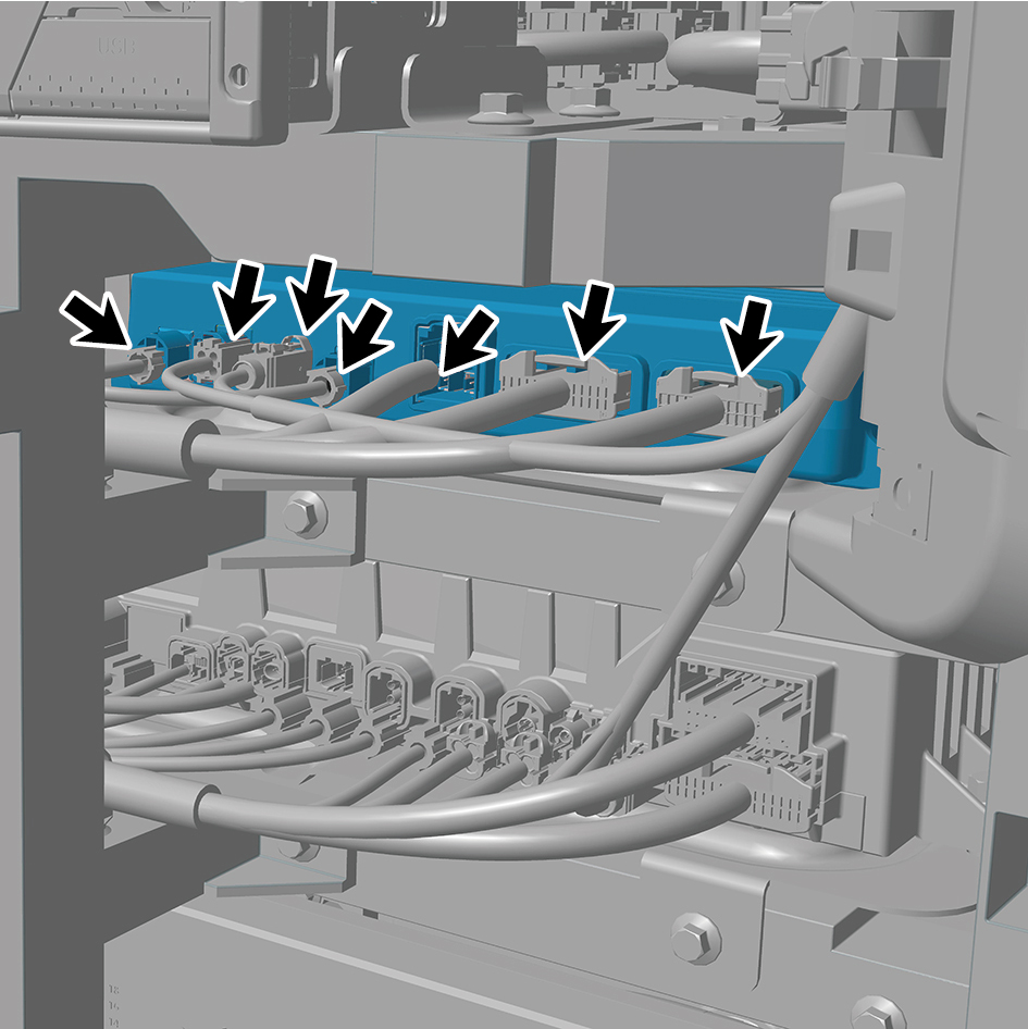
14
Remove 4 fixing bolts of the TGW with bracket, and
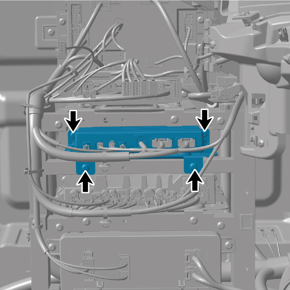
remove the TGW with bracket.
15
Remove 4 fixing bolts of the TGW.
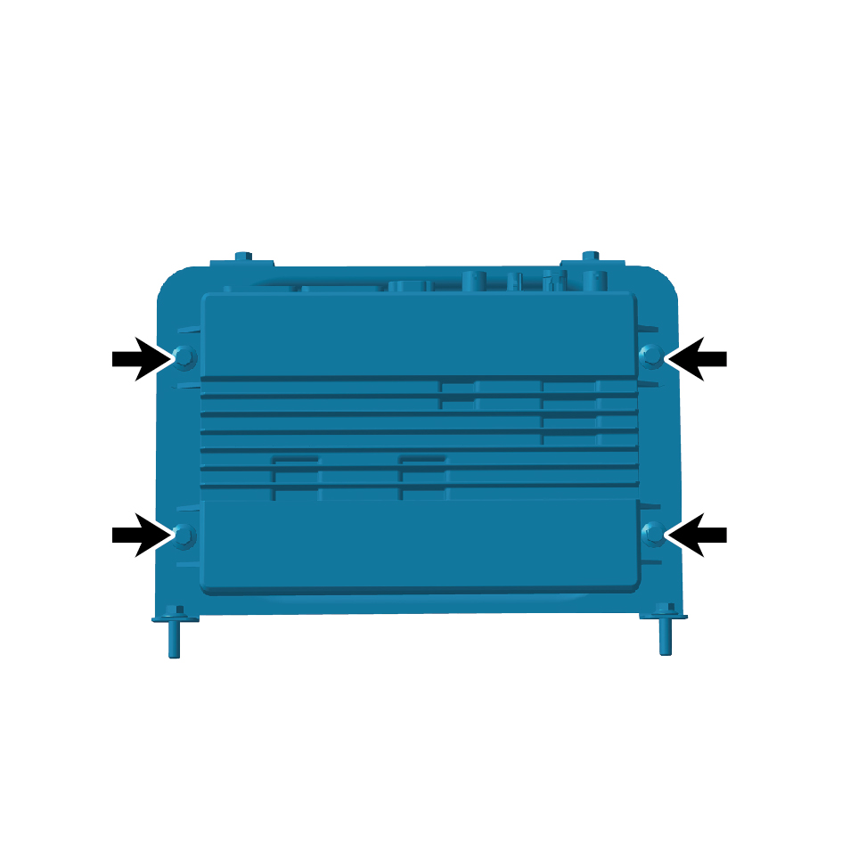
16
Remove the TGW.
Installation Procedures
1
Move the TGW to the mounting position.
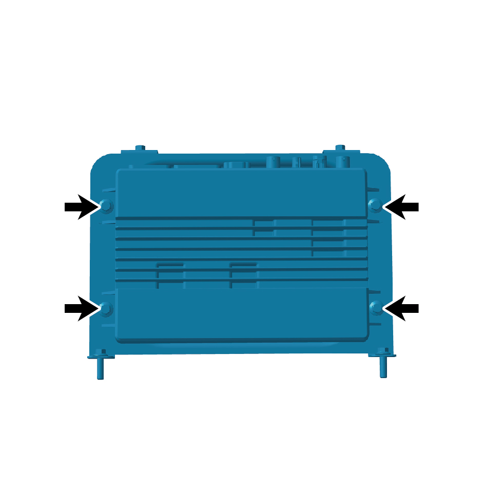
2
Install 4 fixing bolts of the TGW.
Torque:(6.5 +/+.75) ft lbs
3
Install the TGW with bracket, and install 4 fixing bolts of
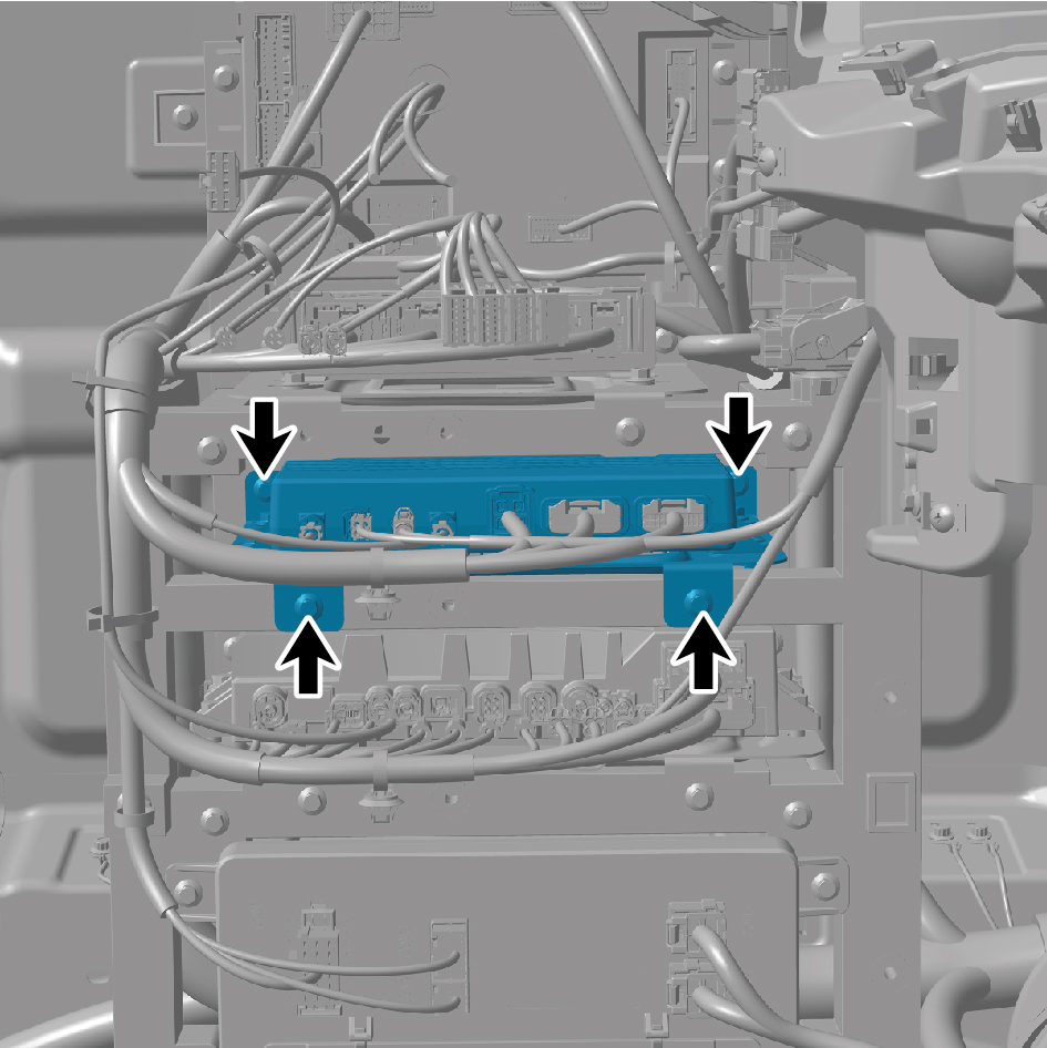
the TGW with bracket.
4
Connect 7 harness connectors of the TGW.
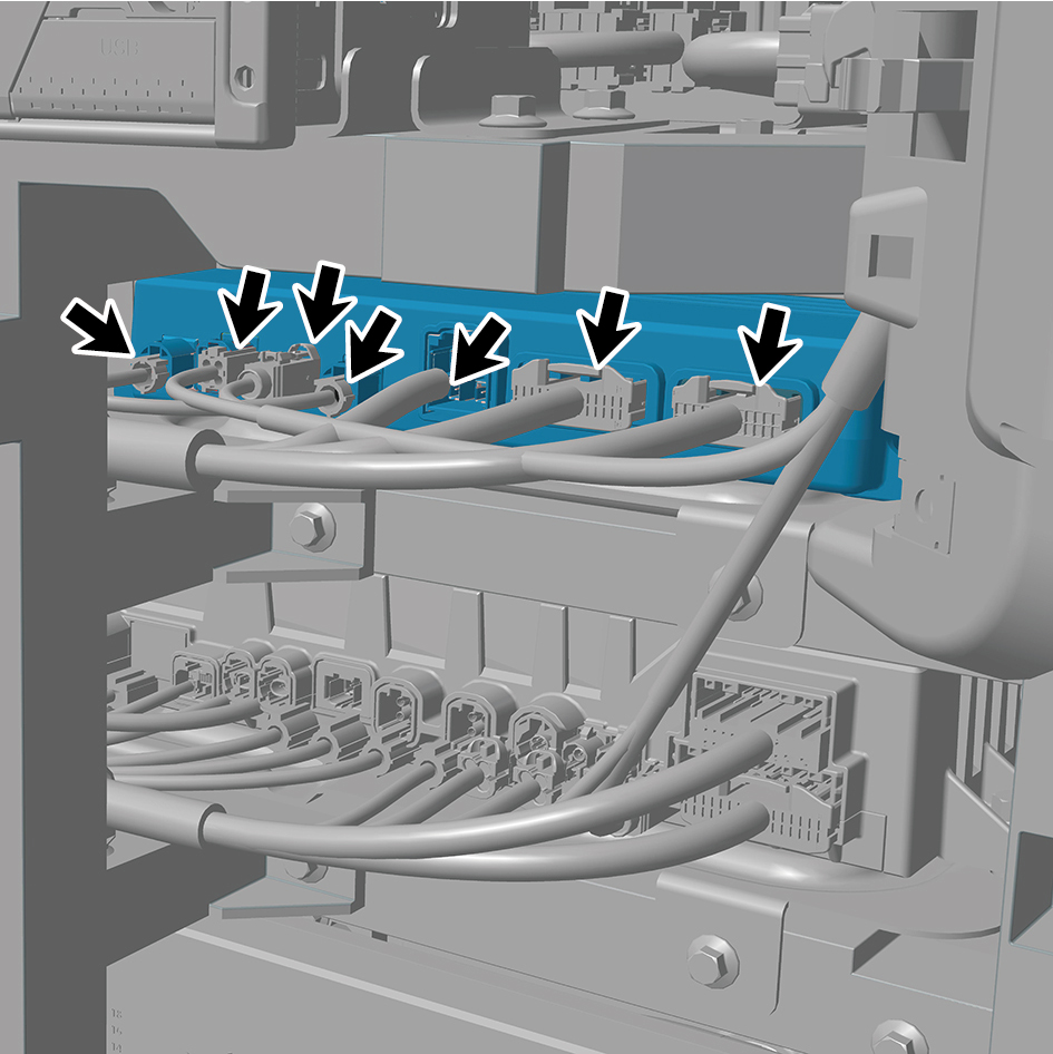
caution
The harness is firmly connected following the
principal of "insert until a click is heard for
confirmation".
5
Install the left lower fixing bracket.
6
Install the VTDR bracket.
7
Install the VTDR.
8
Install the IP left lower trim panel assembly.
9
Install the left switch panel lower trim panel assembly.
10
Install the left switch panel assembly.
11
Install the IP left access cover plate assembly.
12
Install the IP left upper trim panel assembly.
13
Install the front USB interface.
14
Connect the battery negative cable.
15
Close the front flip cover plate.
16
Close the door.