← Back to Contents
7 Automotive Electrical Appliances / 7.12 Interior Vehicle Body Lamp Device | PDF pages 1718-1735
7.12 Interior Vehicle Body Lamp Device
7.12 Interior Vehicle Body Lamp Device
7.12.1 Specifications
7.12.1.1 Fastener Specifications
Range Of Torque
Fastener Specifications
Specifications
Foot Pounds of Torque (ft lbs)
The fixing bolt connecting the toolbox
(6.5 +/- .75) ft lbs
M6
light bracket to the sleeper toolbox
7.12.1.2 Technical Parameters
Name of Llight Bulb
Model of Light Bulb
Quantity
Power
Brake light
2
LED
1.1W
Turn signal
2
LED
1.1W
Position light
2
LED
0.2W
Reverse light
2
LED
1.5W
License plate light
2
LED
0.7W
High beam
2
LED
32.0W
Low beam
2
LED
40.0W
Daytime Running Lights
2
LED
14.0W
Front turn signal
2
LED
14.0W
Front position light
2
LED
6.6W
Front side marker light
2
LED
1.7W
Identification Light
3
LED
1.7W
Rear work light
1
LED
9.0W
Side marker light
2
LED
1.5W
Ceiling light
2
LED
9.5W
Front reading light
2
LED
0.6W
Berth reading light
1
LED
1.3W
Illuminating lamp
3
LED
0.5W
Ambient light
2
LED
0.4W
7.12.2 Decomposition Diagram
7.12.2.1 Decomposition Diagram
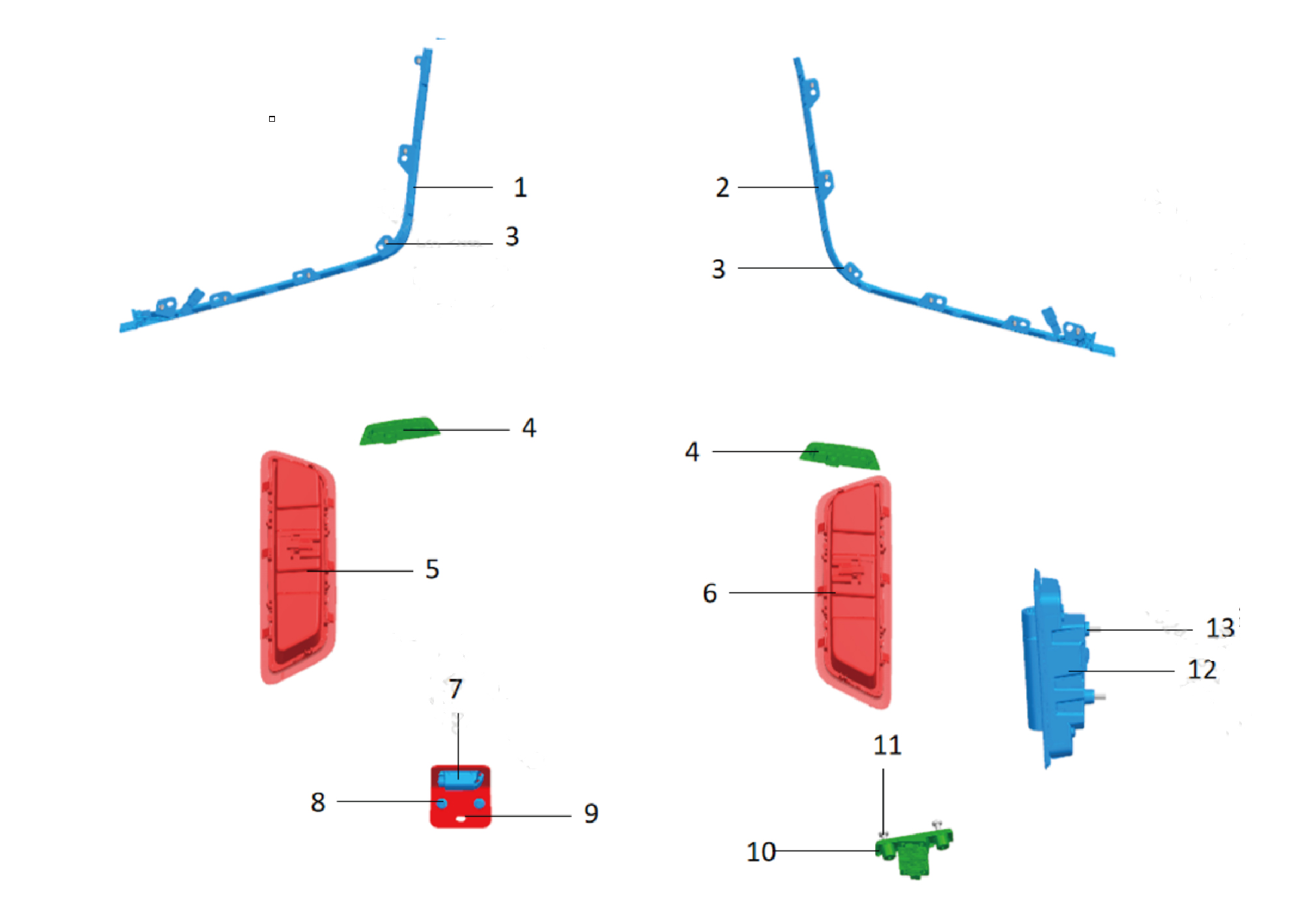
1.
Atmosphere Lamp -Instrument Trim Panel Lh Upr
8.
Hexagon Flange Bolt
2.
9.
Tool Box Lamp Bracket
Atmosphere Lamp of Right Workbench
3.
10.
Self-Tapping Screw
Courtesy Lamp
4.
Reading Lamp-Frt
11.
Hexalobular Socket Pan Head Screw In New Energy
Vehicles
5.
12.
Ceiling Lamp-Lh
Sleeper Reading Lamp
6.
13.
Ceiling lamp-rh
Cross Recessed Pan Head Machine Screw
7.
Lamp
7.12.3 Dismantling and Installation
7.12.3.1 Replacement of Lighting Lamp
Removal Procedures
1
Open the door.
2
Open the front flip cover plate.
3
Disconnect the battery negative cable.
caution
power down the high-voltage system before
disconnecting the negative pole of the storage
battery.
4
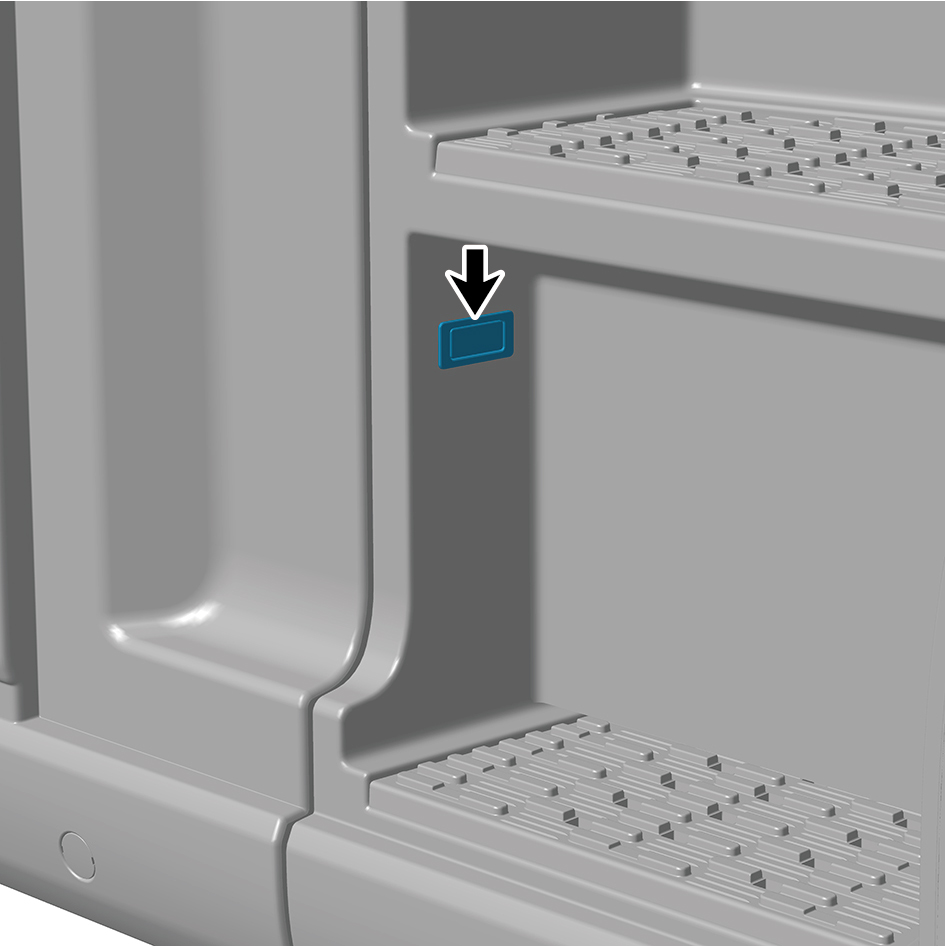
Detach the lighting lamp.
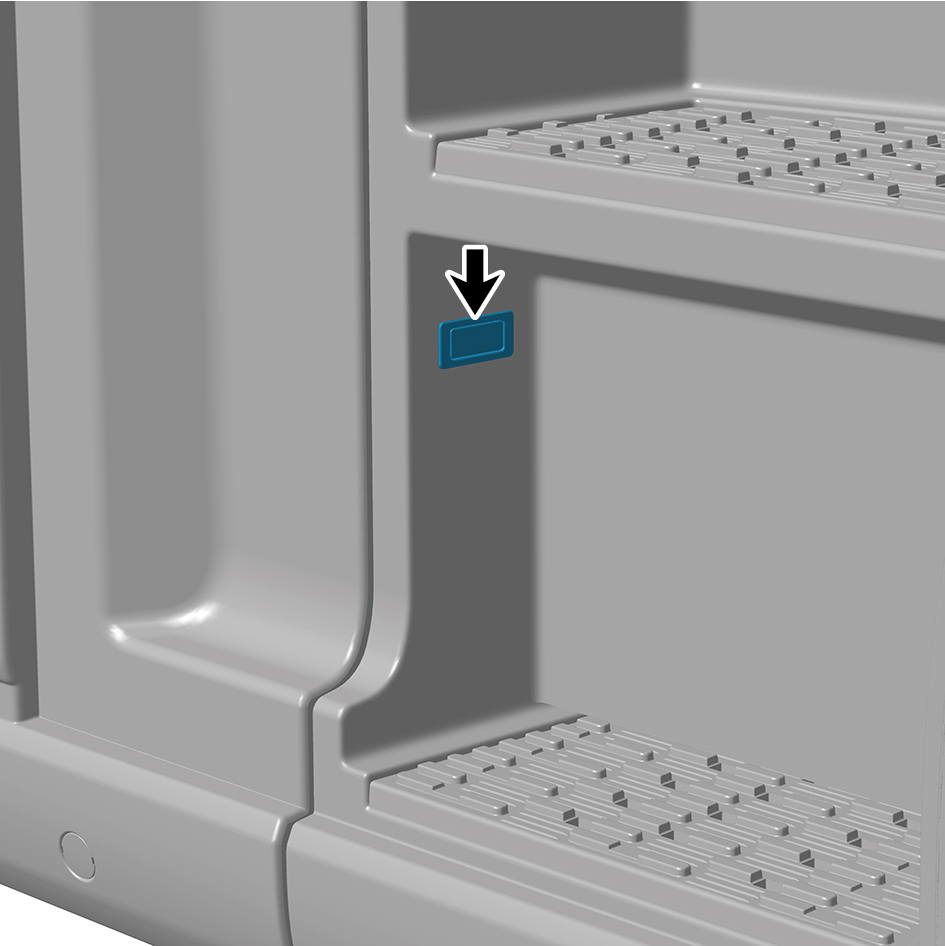
5
Disconnect 1 harness connector of the lighting lamp.
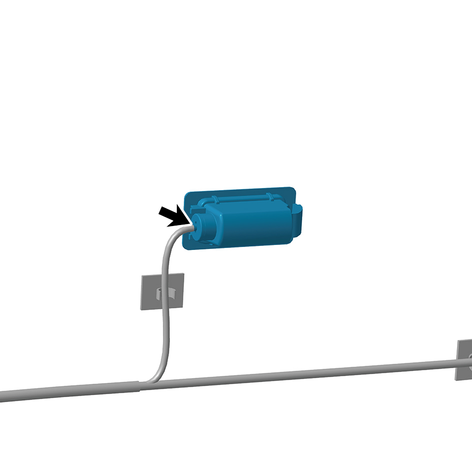
6
Remove the lighting lamp.
Installation Procedures
1
Move the lighting lamp to the mounting position.
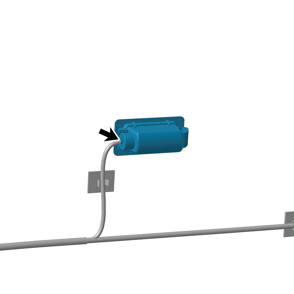
2
Connect 1 harness connector of the lighting lamp.
caution
The harness is firmly connected following the
principal of "insert until a click is heard for
confirmation".
3
Install the lighting lamp.
4
Connect the battery negative cable.
5
Close the front flip cover plate.
6
Close the door.
7.12.3.2 Replacement of Courtesy Lamp
Removal Procedures
1
Open the door.
2
Open the front flip cover plate.
3
Disconnect the battery negative cable.
caution
power down the high-voltage system before
disconnecting the negative pole of the storage
battery.
4
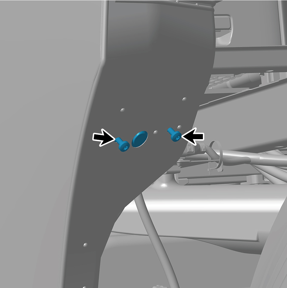
Remove 2 fixing screws of the courtesy lamp, and detach
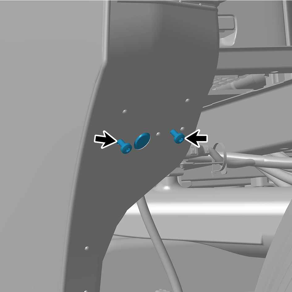
the courtesy lamp.
5
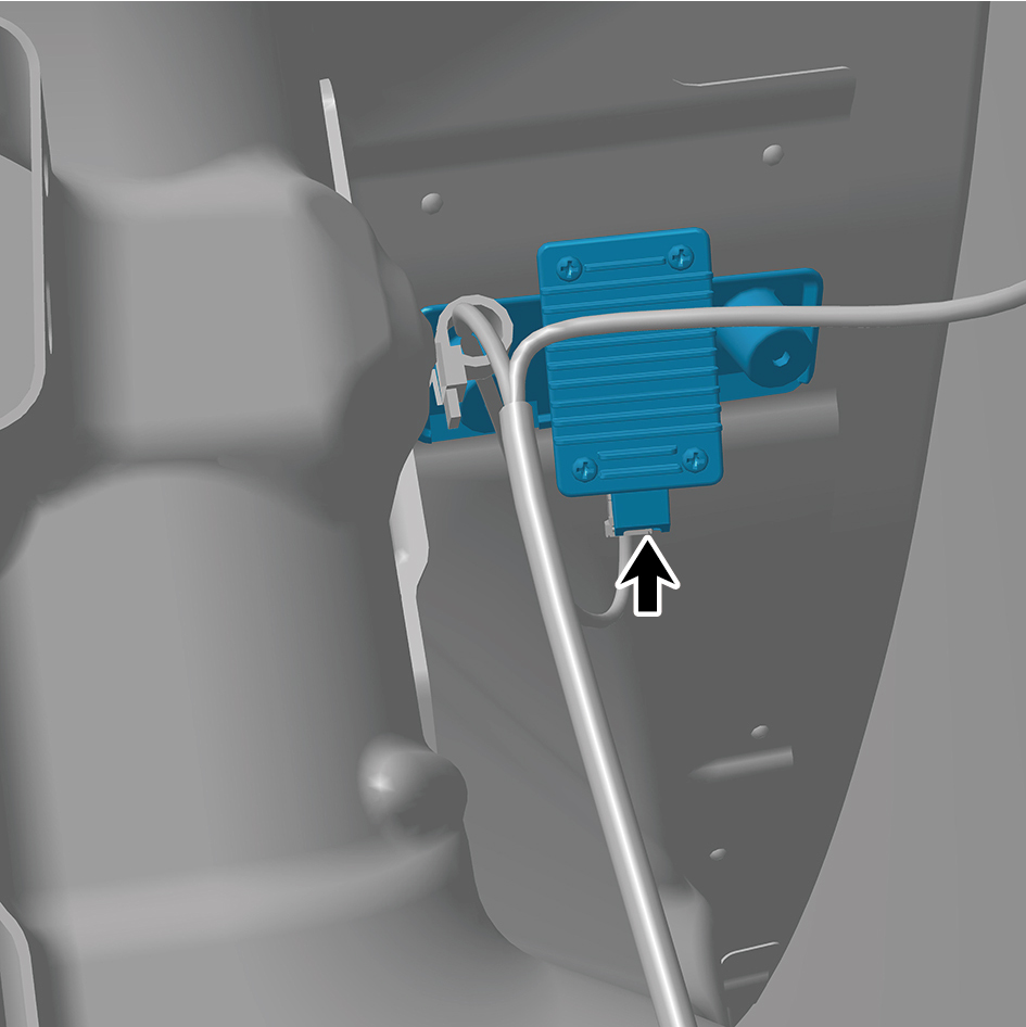
Disconnect 1 harness connector of the courtesy lamp.
6
Remove the courtesy lamp.
Installation Procedures
1
Move the courtesy lamp to the mounting position.
2
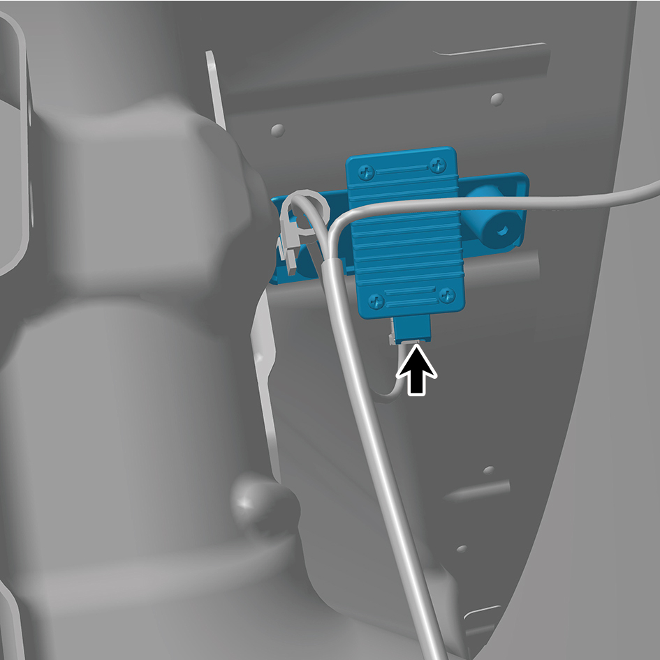
Connect 1 harness connector of the courtesy lamp.
caution
The harness is firmly connected following the
principal of "insert until a click is heard for
confirmation".
3
Install 2 fixing screws of the courtesy lamp.
4
Connect the battery negative cable.
5
Close the front flip cover plate.
6
Close the door.
7.12.3.3 Replacement of Sleeper Reading Lamp
Lamp
Removal Procedures
1
Open the door.
2
Open the front flip cover plate.
3
Disconnect the battery negative cable.
caution
power down the high-voltage system before
disconnecting the negative pole of the storage
battery.
4
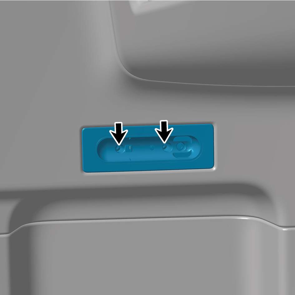
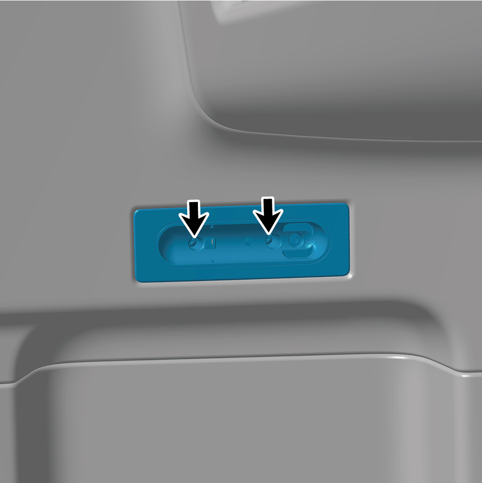
Remove 2 fixing screws of the sleeper reading lamp.
5
Disconnect 1 harness connector of the sleeper reading
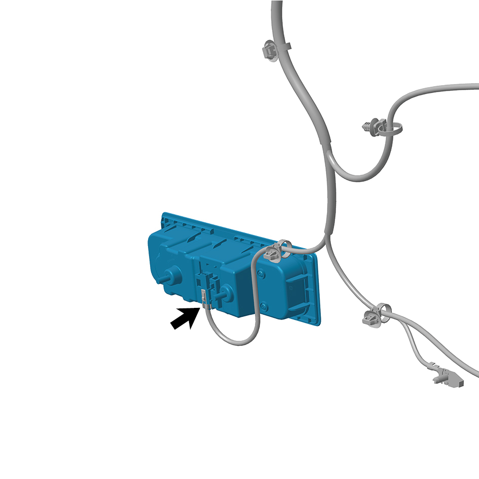
lamp.
6
Remove the sleeper reading lamp.
Installation Procedures
1
Move the sleeper reading lamp to the mounting position.
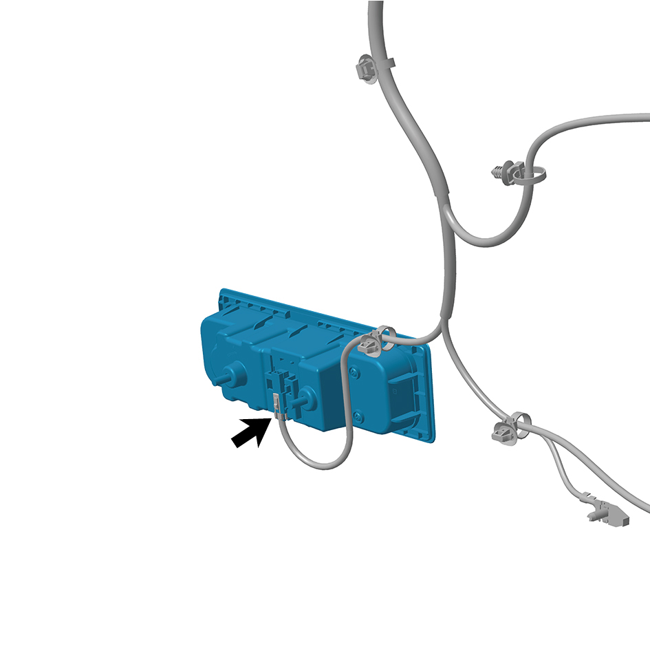
2
Connect 1 harness connector of the sleeper reading lamp.
caution
The harness is firmly connected following the
principal of "insert until a click is heard for
confirmation".
3
Install 2 fixing screws of the sleeper reading lamp.
4
Connect the battery negative cable.
5
Close the front flip cover plate.
6
Close the door.
7.12.3.4 Replacement of Instrument Left Upper Trim Panel Ambient Lamp
Trim Panel Ambient Lamp
Removal Procedures
1
Open the door.
2
Open the front flip cover plate.
3
Disconnect the battery negative cable.
caution
power down the high-voltage system before
disconnecting the negative pole of the storage
battery.
4
Remove the IP left upper trim panel assembly.
5
Remove 6 fixing screws on the instrument left upper trim
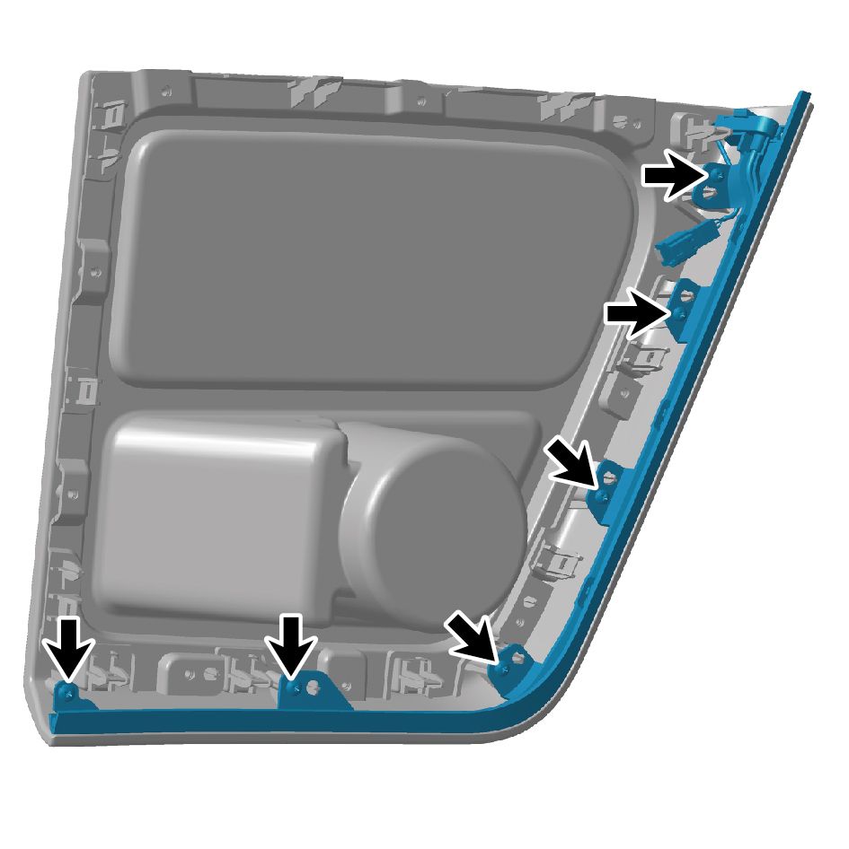
panel ambient lamp.
6
Remove the instrument left upper trim panel ambient
lamp.
Installation Procedures
1
Move the instrument left upper trim panel ambient lamp to
the mounting position.
2
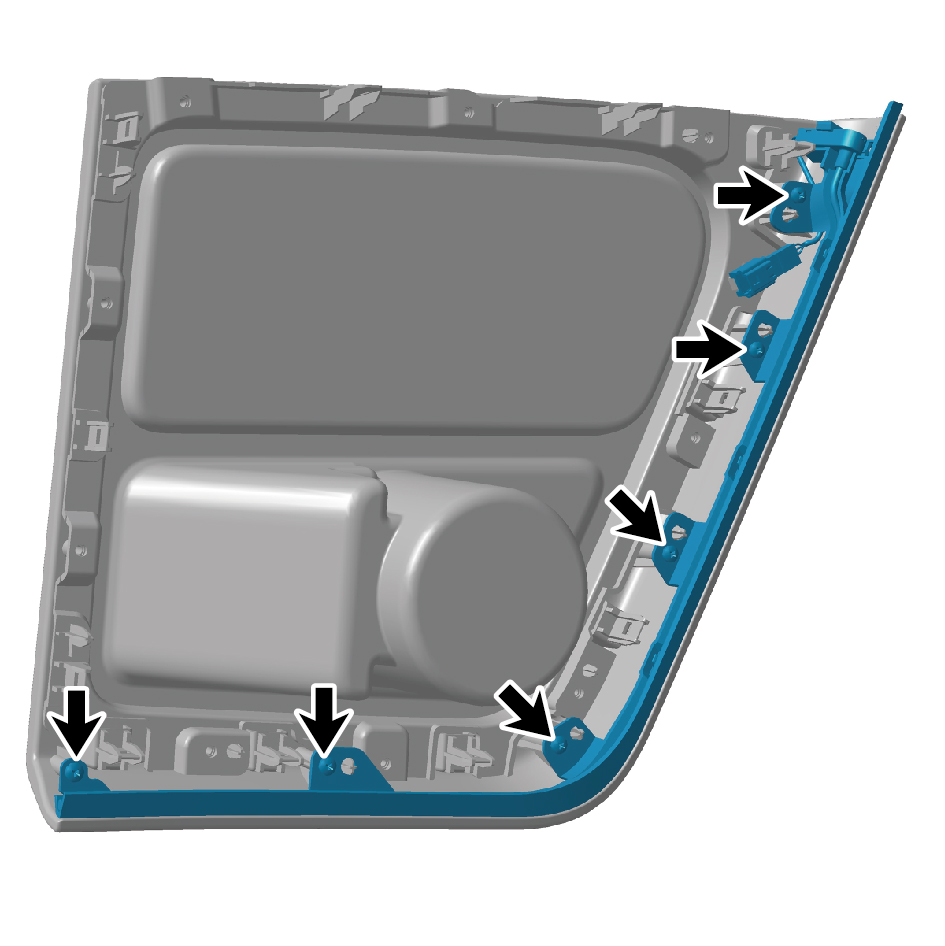
Install 6 fixing screws on the instrument left upper trim
panel ambient lamp.
3
Install the IP left upper trim panel assembly.
4
Connect the battery negative cable.
5
Close the front flip cover plate.
6
Close the door.
7.12.3.5 Replacement of Right Workbench Ambient Lamp
Ambient Lamp
Removal Procedures
1
Open the door.
2
Open the front flip cover plate.
3
Disconnect the battery negative cable.
caution
power down the high-voltage system before
disconnecting the negative pole of the storage
battery.
4
Remove the IP right upper trim panel assembly.
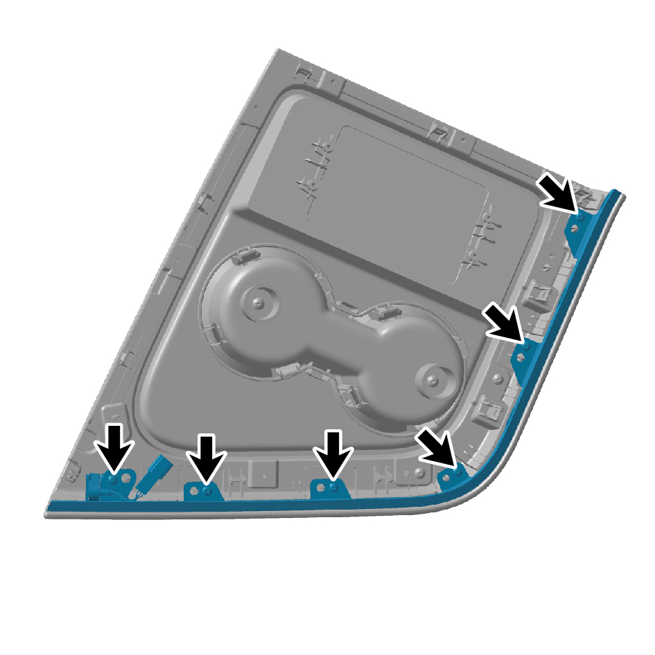
5
Remove 6 fixing screws on the right workbench ambient
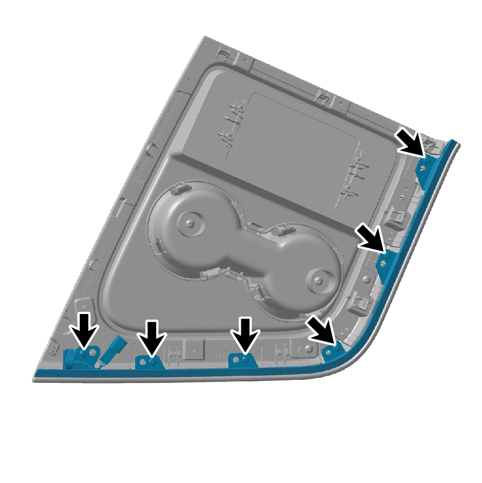
lamp.
6
Remove the right workbench ambient lamp.
Installation Procedures
1
Move the right workbench ambient lamp to the mounting
position.
2
Install 6 fixing screws on the right workbench ambient
lamp.
3
Install the IP right upper trim panel assembly.
4
Connect the battery negative cable.
5
Close the front flip cover plate.
6
Close the door.
7.12.3.6 Replacement of Toolbox Lamp Bracket
Bracket
Removal Procedures
1
Open the door.
2
Open the front flip cover plate.
3
Disconnect the battery negative cable.
caution
power down the high-voltage system before
disconnecting the negative pole of the storage
battery.
4
Remove the toolbox lamp.
5
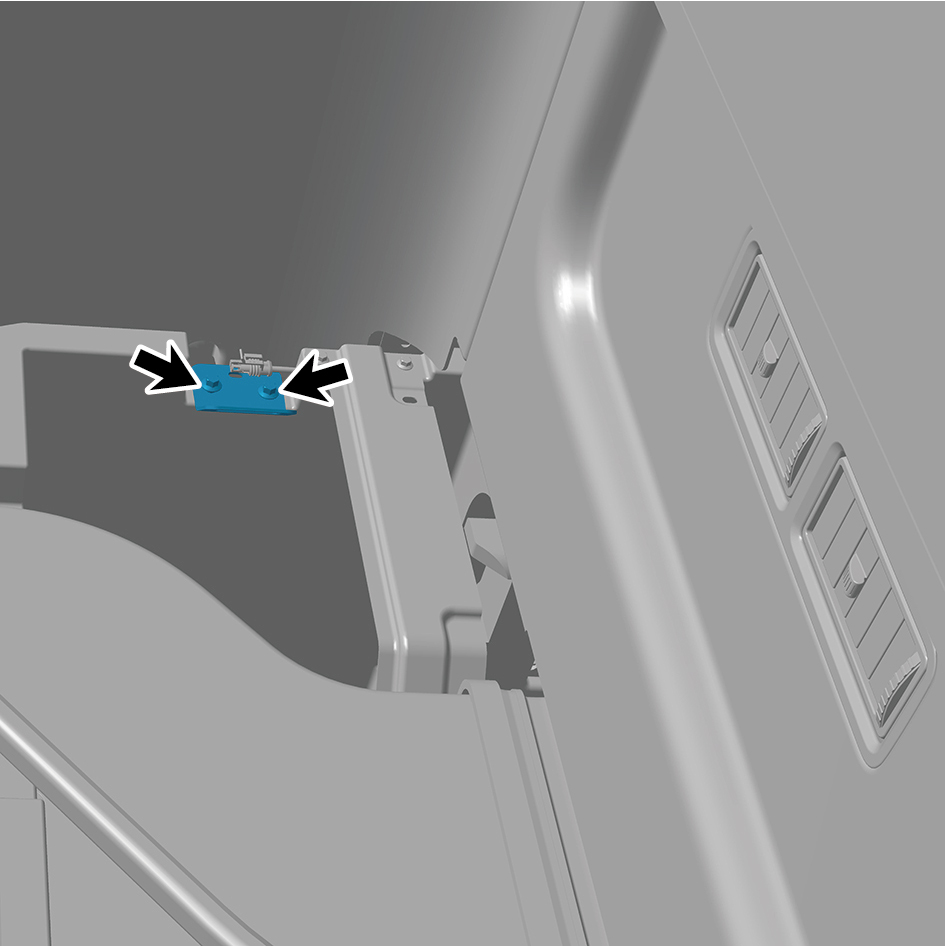
Remove 2 fixing bolts of the toolbox lamp bracket
6
Remove the toolbox lamp bracket.
Installation Procedures
1
Move the toolbox lamp bracket to the mounting position.
2
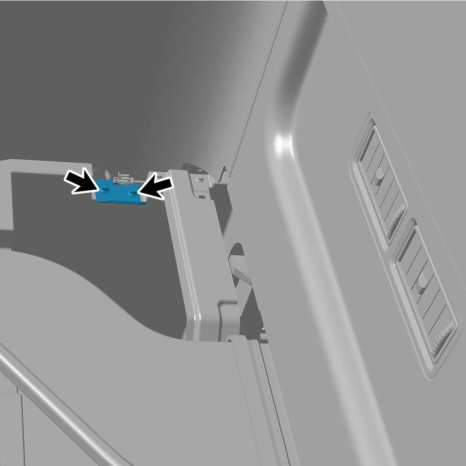
Install 2 fixing bolts of the toolbox lamp bracket
Torque: (6.5 +/- .75) ft lbs
3
Install the toolbox lamp.
4
Connect the battery negative cable.
5
Close the front flip cover plate.
6
Close the door.
7.12.3.7 Replacement of Left Ceiling Lamp
Removal Procedures
1
Open the door.
2
Open the front flip cover plate.
3
Disconnect the battery negative cable.
caution
power down the high-voltage system before
disconnecting the negative pole of the storage
battery.
4
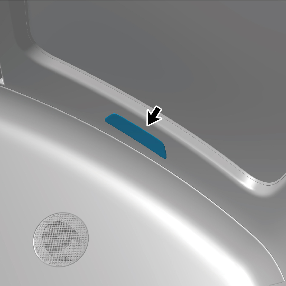
Pry off the left ceiling lamp.
5
Disconnect 1 harness connector of the left ceiling lamp.
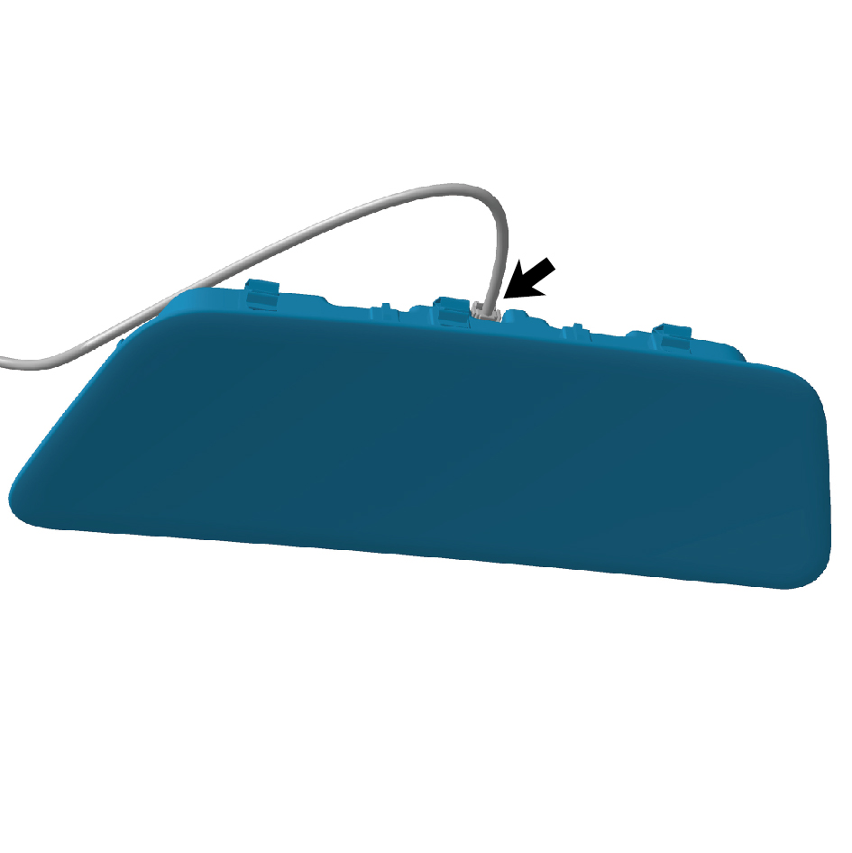
6
Remove the left ceiling lamp.
Installation Procedures
1
Move the left ceiling lamp to the mounting position.
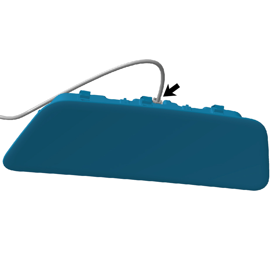
2
Connect 1 harness connector of the left ceiling lamp.
caution
The harness is firmly connected following the
principal of "insert until a click is heard for
confirmation".
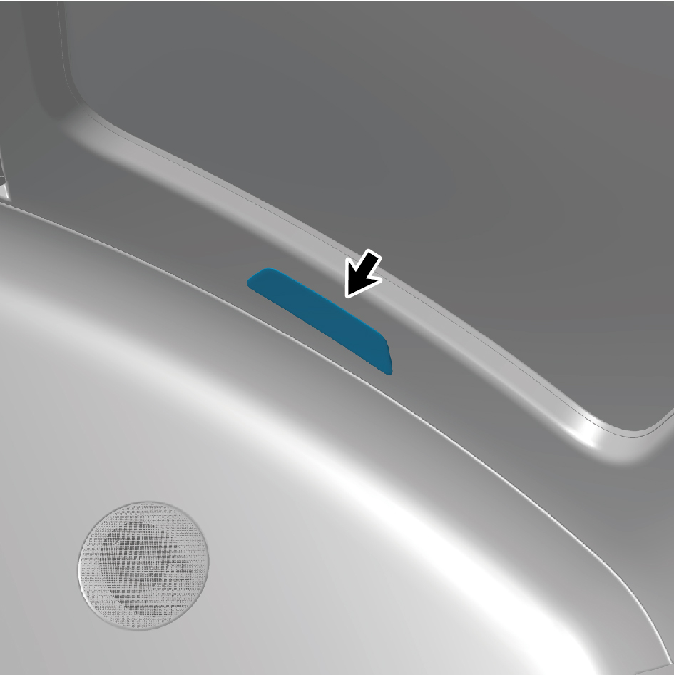
3
Install the left ceiling lamp.
4
Connect the battery negative cable.
5
Close the front flip cover plate.
6
Close the door.
7.12.3.8 Replacement of Right Ceiling Lamp
Removal Procedures
1
Open the door.
2
Open the front flip cover plate.
3
Disconnect the battery negative cable.
caution
power down the high-voltage system before
disconnecting the negative pole of the storage
battery.
4
Pry off the right ceiling lamp.
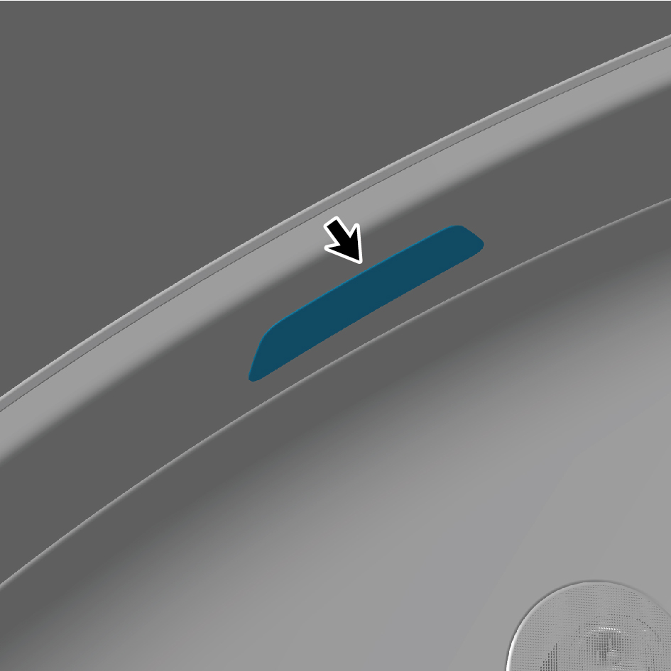
5
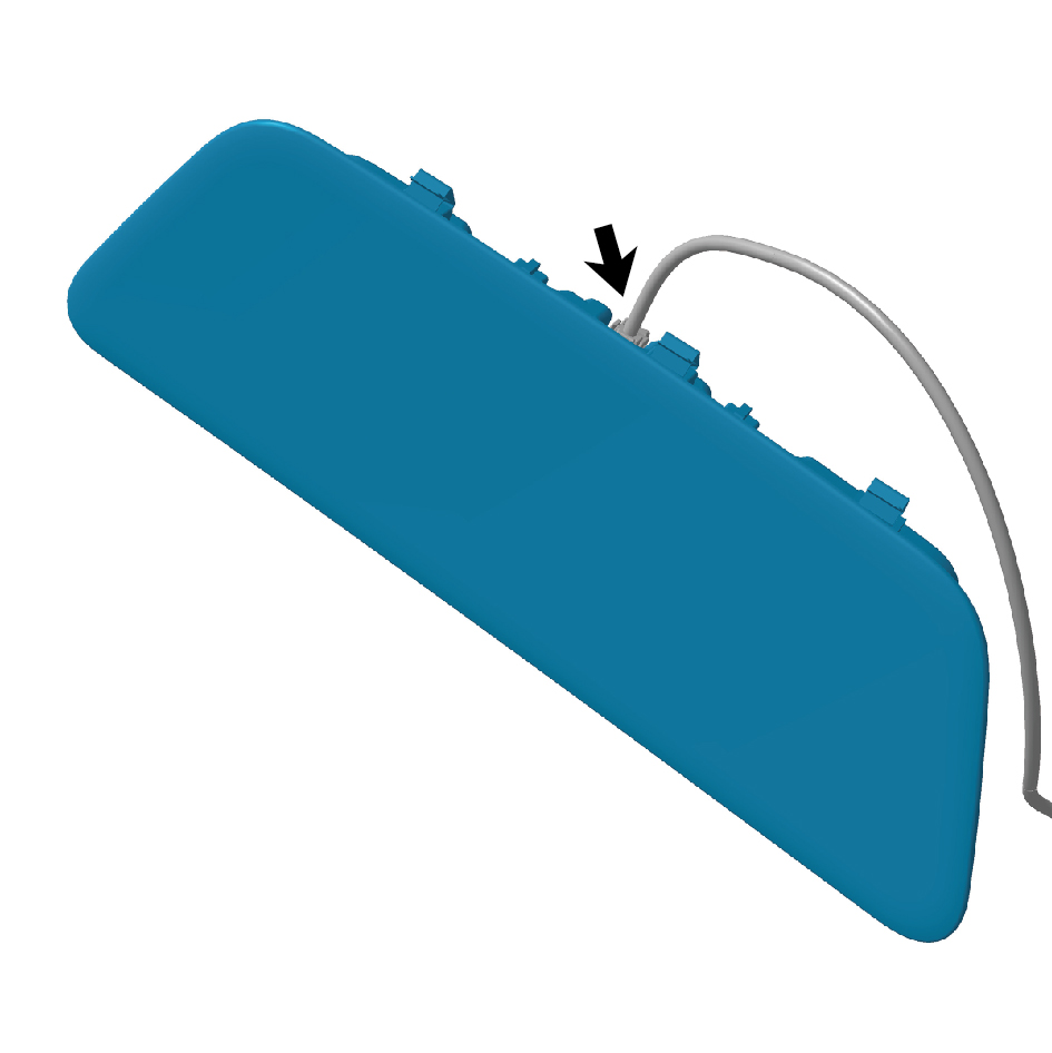
Disconnect 1 harness connector of the right ceiling lamp.
6
Remove the right ceiling lamp.
Installation Procedures
1
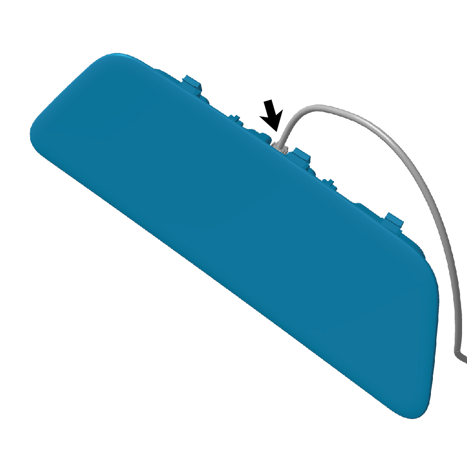
Move the right ceiling lamp to the mounting position.
2
Connect 1 harness connector of the right ceiling lamp.
caution
The harness is firmly connected following the
principal of "insert until a click is heard for
confirmation".
3
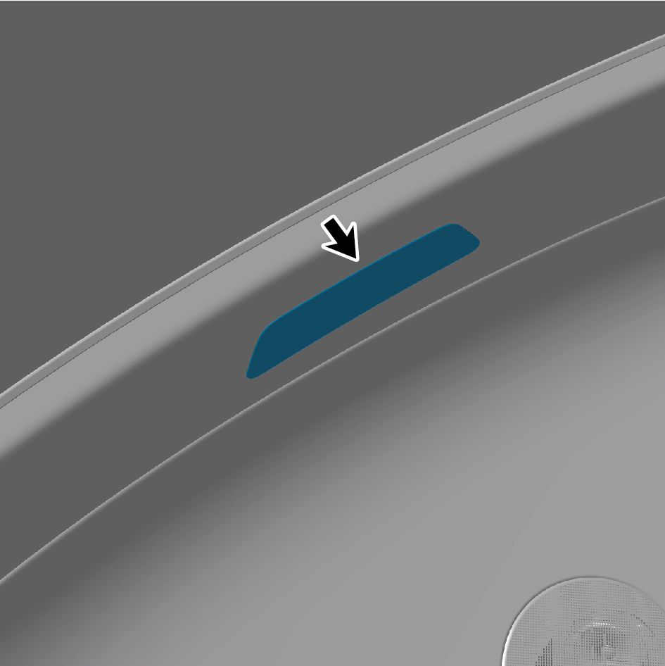
Install the right ceiling lamp.
4
Connect the battery negative cable.
5
Close the front flip cover plate.
6
Close the door.
7.12.3.9 Replacement of Front Reading Lamp
Removal Procedures
1
Open the door.
2
Open the front flip cover plate.
3
Disconnect the battery negative cable.
caution
power down the high-voltage system before
disconnecting the negative pole of the storage
battery.
4
Remove the left A-pillar protective plate assembly.
5
Remove the right A-pillar protective plate assembly.
6
Remove the sunshade rail assembly.
7
Remove the front camera trim cover assembly.
8
Remove the sunshade cover plate assembly.
9
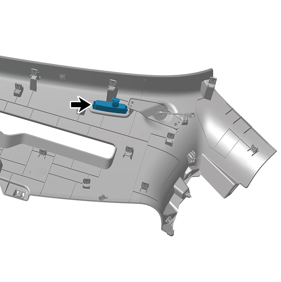
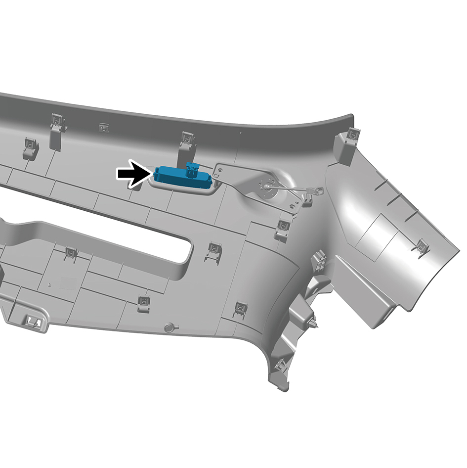
Remove the front reading lamp.
Installation Procedures
1
Install the front reading lamp.
2
Install the sunshade cover plate assembly.
3
Install the front camera trim cover assembly.
4
Install the sunshade rail assembly.
5
Install the right A-pillar protective plate assembly.
6
Install the left A-pillar protective plate assembly.
7
Connect the battery negative cable.
8
Close the front flip cover plate.
9
Close the door.
7.12.3.10 Replacement of Top Cabinet Lamp
Removal Procedures
1
Open the door.
2
Open the front flip cover plate.
3
Disconnect the battery negative cable.
caution
power down the high-voltage system before
disconnecting the negative pole of the storage
battery.
4
Open the top cabinet assembly.
5
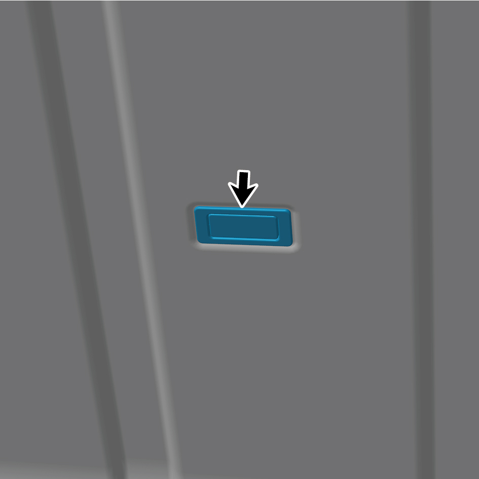
Detach the top cabinet lamp.
6
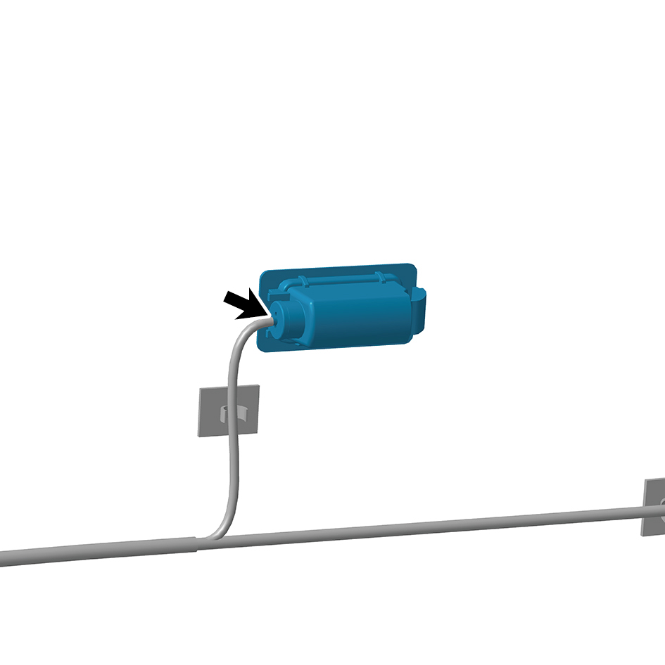
Disconnect 1 harness connector of the top cabinet lamp.
7
Remove the top cabinet lamp.
Installation Procedures
1
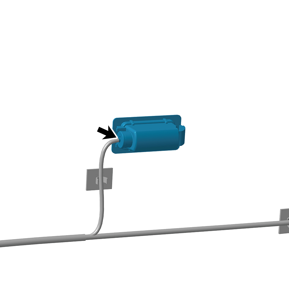
Move the top cabinet lamp to the mounting position.
2
Connect 1 harness connector of the top cabinet lamp.
3
Install the top cabinet lamp.
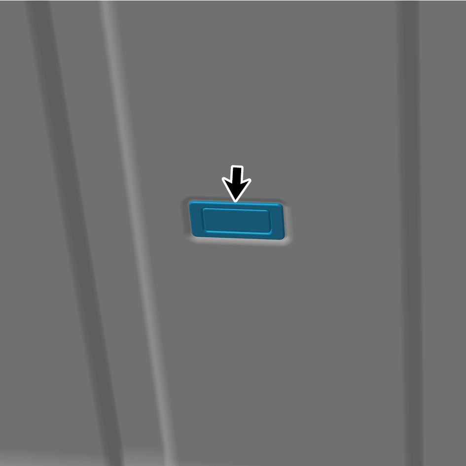
4
Close the top cabinet assembly.
5
Connect the battery negative cable.
6
Close the front flip cover plate.
7
Close the door.