← Back to Contents
7 Automotive Electrical Appliances / 7.11 Exterior Vehicle Body Lamp Device | PDF pages 1673-1717
7.11 Exterior Vehicle Body Lamp Device
7.11 Exterior Vehicle Body Lamp Device
7.11 Exterior Vehicle Body Lamp
Device
7.11.1 Specifications
7.11.1.1 Fastener Specifications
Range Of Torque
Fastener Specifications
Specifications
Foot Pounds of Torque (ft lbs)
The fixing bolt connecting the left
(6 +/- .75) ft lbs
M8
headlight to the left headlight bracket
The fixing bolt connecting the left
headlight bracket to the front lower
(18.5 +/- 2) ft lbs
M12
protective assembly
The fixing bolt connecting the left
headlight bracket to the A-pillar exterior
(18.5 +/- 2) ft lbs
M8
decoration assembly
The fixing bolt connecting the left
headlight bracket and the side fender
(6.5 +/- .75) ft lbs
M8
bracket assembly
The fixing bolt connecting the left
headlight bracket to the left front
(18.5 +/- 2) ft lbs
M8
connecting beam
The fixing bolt connecting the right
(6 +/- .75) ft lbs
M8
headlight to the right headlight bracket
The fixing bolt connecting the right
headlight bracket to the front lower
(17 +/- 2) ft lbs
M12
protective assembly
The fixing bolt connecting the right
headlight bracket to the A-pillar exterior
(17 +/- 2) ft lbs
M8
decoration assembly
The fixing bolt connecting the right
headlight bracket and the side fender
(6.5 +/- .75) ft lbs
M8
bracket assembly
The fixing bolt connecting the right
headlight bracket to the right front
(17 +/- 2) ft lbs
M8
connecting beam
The fixing bolt connecting the through
light and the bumper body skeleton
(6.5+/- .75) ft lb
M6
assembly
The fixing bolt connecting the right front
combination lamp and the right front
(6.5+/- .75) ft lb
M6
headlight bracket
Range Of Torque
Fastener Specifications
Specifications
Foot Pounds of Torque (ft lbs)
The fixing bolt connecting the left front
combination lamp and the left fender
(6.5+/- .75) ft lb
M6
bracket assembly
The fixing bolt connecting the right front
combination lamp and the left fender
(6.5+/- .75) ft lb
M6
bracket assembly
The fixing nut connecting the left front
clearance lamp to the top cover
(6.5+/- .75) ft lb
M6
assembly
The fixing nut connecting the right front
clearance lamp to the top cover
(6.5+/- .75) ft lb
M6
assembly
The fixing bolt connecting the rear
clearance lamp and the rear clearance
(4.5 +/- .75) ft lbs
M6
lamp mounting bracket
The fixing nut connecting the rear
clearance lamp and the rear clearance
(4.5 +/- .75) ft lbs
M6
lamp mounting bracket
The fixing nut connecting the rear work
(18.5 +/- 2) ft lbs
M8
light bracket to the integrated frame
Fixed bolts connecting the rear work
(18.5 +/- 2) ft lbs
M8
light bracket to the integrated frame
The fixing nut connecting the side
marker combination light and the lower
(4.5 +/- .75) ft lbs
M6
decorative panel assembly of the side
panel
The fixing nut connecting the side
marker combination light and the side
(4.5 +/- .75) ft lbs
M6
skirt assembly
7.11.1.2 Technical Parameters
Name of Light Bulb
Quantity
Model of Light Bulb
Power
Low beam
2
LED
40W each
High beam
2
LED
40W each
Front turn signal lamp
2
LED
14W each
Daytime running lamp
2
LED
14W each
Front position lamp
2
LED
6.6W each
End-outline marker lamp
2
LED
1.7W each
Side turn signal lamp
2
LED
5.1W each
Side marker lamp
8
LED
0.82W each
Name of Light Bulb
Quantity
Model of Light Bulb
Power
Reversing lamp
2
LED
2.5W each
Rear end-outline marker
1.3W for the rear upper,
4
LED
lamp
0.63W for the rear lower
Brake lamp
2
LED
2.9W each
Rear working lamp
1
LED
9W
License plate lamp
1
LED
2.5W
Rear turn signal lamp
2
LED
2.1W
7.11.2 Dismantling and Installation
7.11.2.1 Replacement of Left Headlamp
Removal Procedures
1
Open the door.
2
Open the front flip cover plate.
3
Disconnect the battery negative cable.
caution
power down the high-voltage system before
disconnecting the negative pole of the storage
battery.
4
Remove the engine compartment trim panel body.
5
Remove the through-type lamp.
6
Remove the front MMW radar shield.
7
Remove the forward MMW radar.
8
Remove the front MMW radar adapter bracket.
9
Remove the left cover plate of the corner radar.
10
Remove the right cover plate of the corner radar.
11
Remove the front bumper assembly.
12
Disconnect 2 harness connectors of the left headlamp.
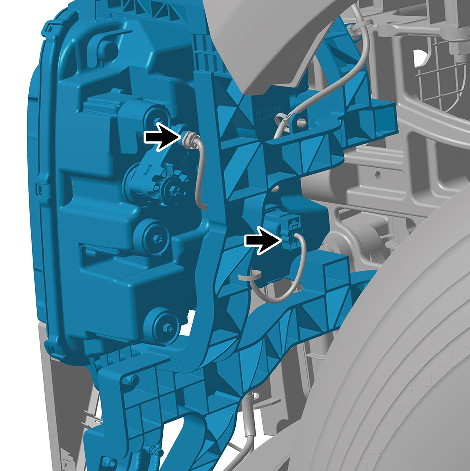
13
Remove 4 fixing bolts of the left headlamp.
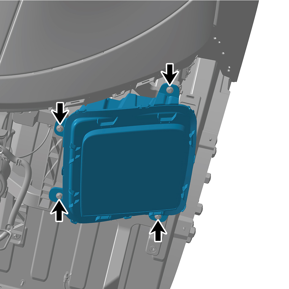
14
Remove the left headlamp.
Installation Procedures
1
Move the left headlamp to the mounting position.
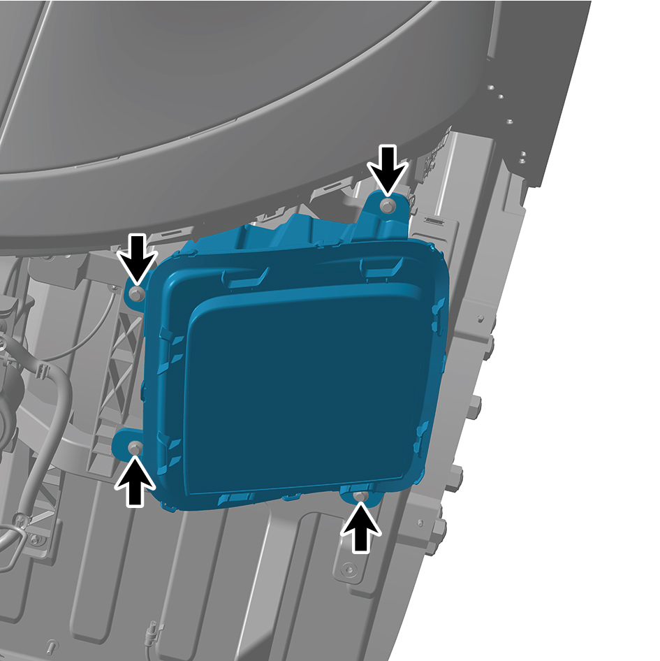
2
Install 4 fixing bolts of the left headlamp.
Torque:(6 +/- .75) ft lbs
3
Connect 2 harness connectors of the left headlamp.
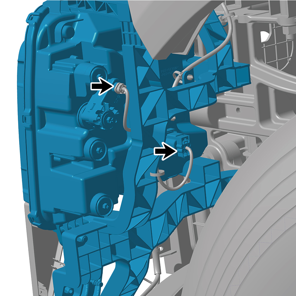
caution
The harness is firmly connected following the
principal of "insert until a click is heard for
confirmation".
4
Install the front bumper assembly.
5
Install the right cover plate of the corner radar.
6
Install the left cover plate of the corner radar.
7
Install the front MMW radar adapter bracket.
8
Install the forward MMW radar.
9
Install the front MMW radar shield.
10
Install the through-type lamp.
11
Install the engine compartment trim panel body.
12
Connect the battery negative cable.
13
Close the front flip cover plate.
14
Close the door.
caution
After replacing the headlamps, it is necessary to
recalibrate the position of the lights.
7.11.2.2 Replacement of Right Headlamp
Removal Procedures
1
Open the door.
2
Open the front flip cover plate.
3
Disconnect the battery negative cable.
caution
power down the high-voltage system before
disconnecting the negative pole of the storage
battery.
4
Remove the engine compartment trim panel body.
5
Remove the through-type lamp.
6
Remove the front MMW radar shield.
7
Remove the forward MMW radar.
8
Remove the front MMW radar adapter bracket.
9
Remove the left cover plate of the corner radar.
10
Remove the right cover plate of the corner radar.
11
Remove the front bumper assembly.
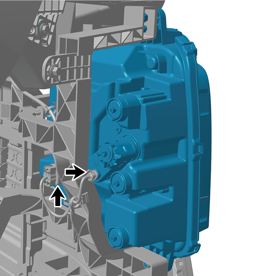
12
Disconnect 2 harness connectors of the right headlamp.
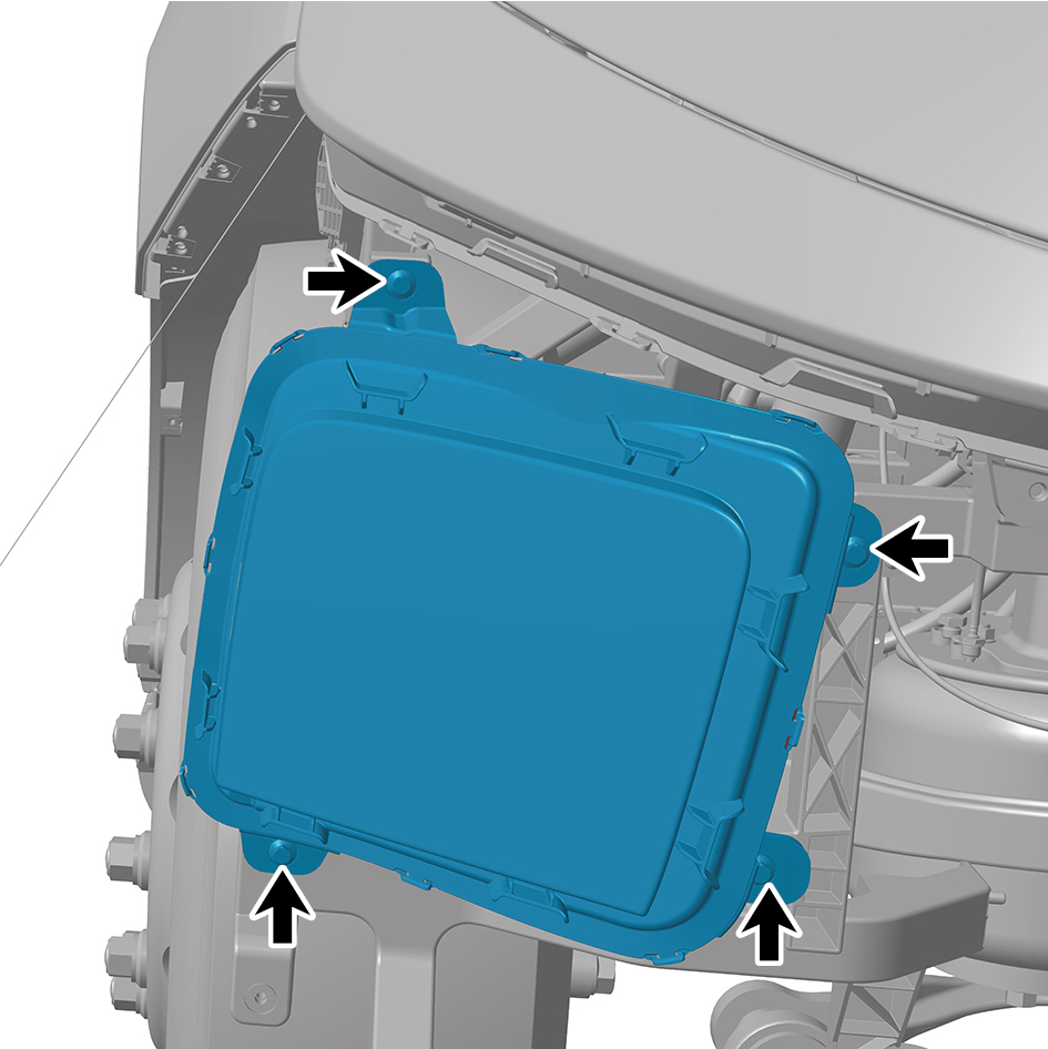
13
Remove 4 fixing bolts of the right headlamp.
14
Remove the right headlamp.
Installation Procedures
1
Move the right headlamp to the mounting position.
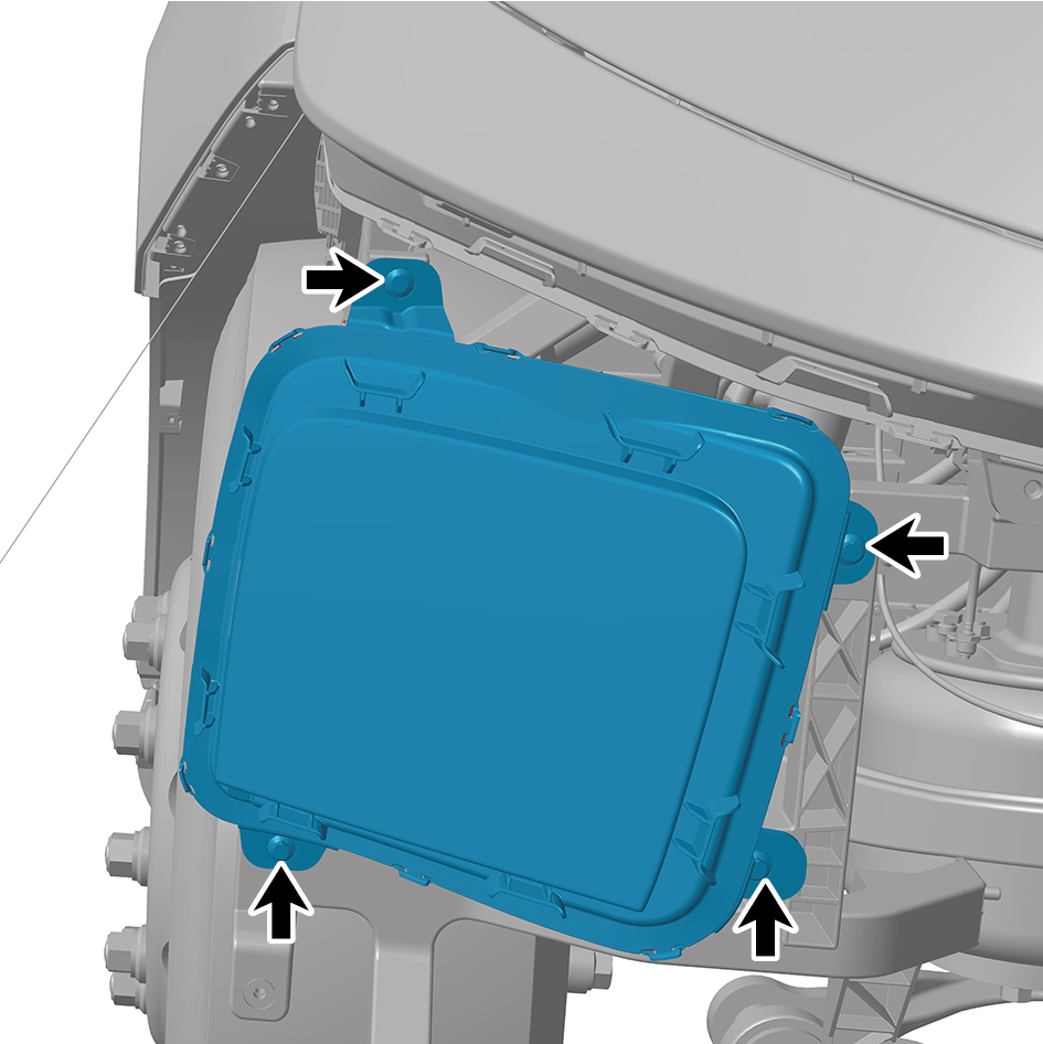
2
Install 4 fixing bolts of the right headlamp.
Torque: (6 +/- .75) ft lbs
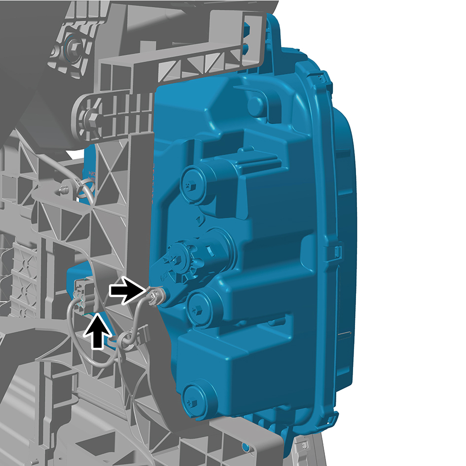
3
Connect 2 harness connector of the right headlamp.
caution
The harness is firmly connected following the
principal of "insert until a click is heard for
confirmation".
4
Install the front bumper assembly.
5
Install the right cover plate of the corner radar.
6
Install the left cover plate of the corner radar.
7
Install the front MMW radar adapter bracket.
8
Install the forward MMW radar.
9
Install the front MMW radar shield.
10
Install the through-type lamp.
11
Install the engine compartment trim panel body.
12
Connect the battery negative cable.
13
Close the front flip cover plate.
14
Close the door.
caution
After replacing the headlamps, it is necessary to
recalibrate the position of the lights.
7.11.2.3 Replacement of Through-type Lamp
Removal Procedures
1
Open the door.
2
Open the front flip cover plate.
3
Disconnect the battery negative cable.
caution
power down the high-voltage system before
disconnecting the negative pole of the storage
battery.
4
Remove the engine compartment trim panel body.
5
Remove 5 fixing bolts of the through-type lamp, and
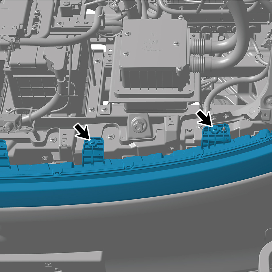
remove the through-type lamp.
Installation Procedures
1
Move the through-type lamp to the mounting position.
2
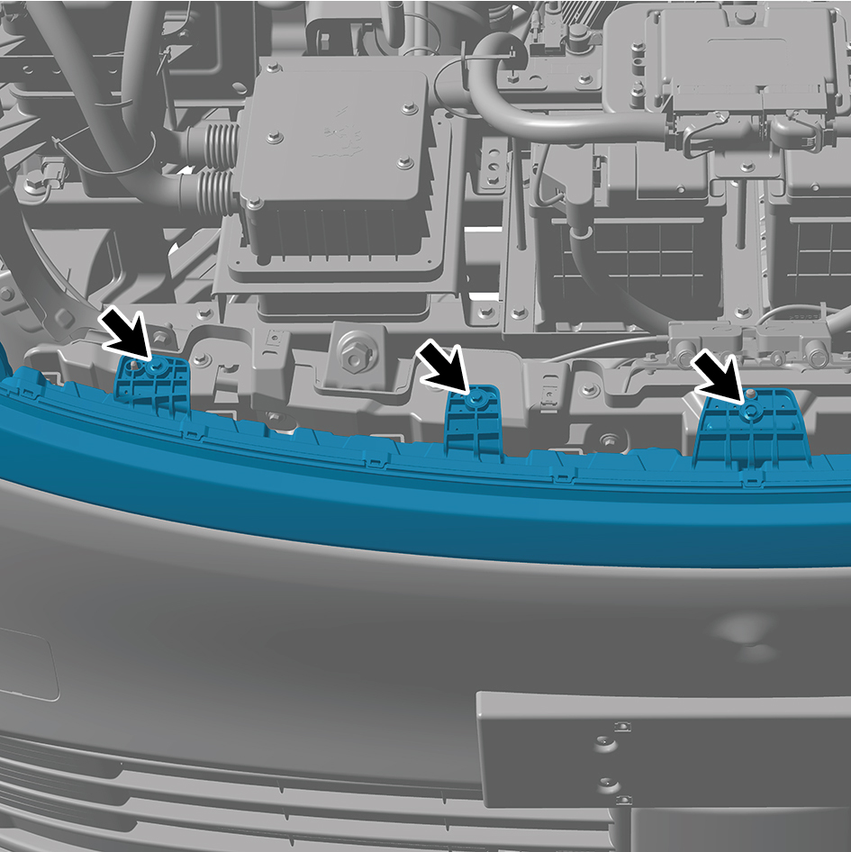
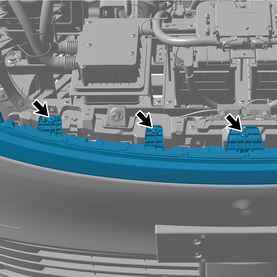
Install 5 fixing bolts of the through-type lamp.
Torque: (6.5 +/- .75) ft lbs

3
Install the engine compartment trim panel body.
4
Connect the battery negative cable.
5
Close the front flip cover plate.
6
Close the door.
7.11.2.4 Replacement of Left Front Combination Lamp
Combination Lamp
Removal Procedures
1
Open the door.
2
Open the front flip cover plate.
3
Disconnect the battery negative cable.
caution
power down the high-voltage system before
disconnecting the negative pole of the storage
battery.
4
Remove the engine compartment trim panel body.
5
Remove the through-type lamp.
6
Remove the front MMW radar shield.
7
Remove the forward MMW radar.
8
Remove the front MMW radar adapter bracket.
9
Remove the left cover plate of the corner radar.
10
Remove the right cover plate of the corner radar.
11
Remove the front bumper assembly.
12
Remove the left physical exterior rearview mirror
assembly.
13
Remove the left front wheel housing body.
14
Remove the primary wiper arm blade assembly (nozzle
and hose).
15
Remove the front windshield cover plate assembly.
16
Remove the left fender trim strip.
17
Remove the left fender assembly.
18
Disconnect 1 harness connector of the left front
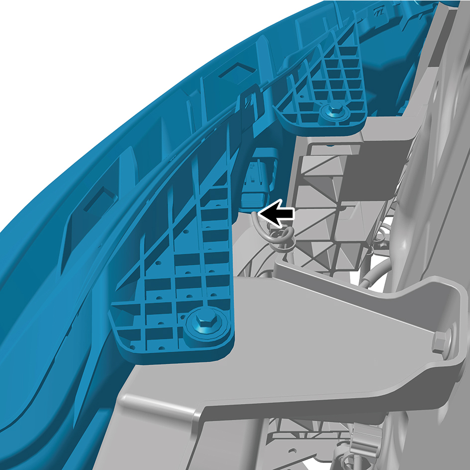
combination lamp.
19
Remove 5 fixing bolts of the left front combination lamp.
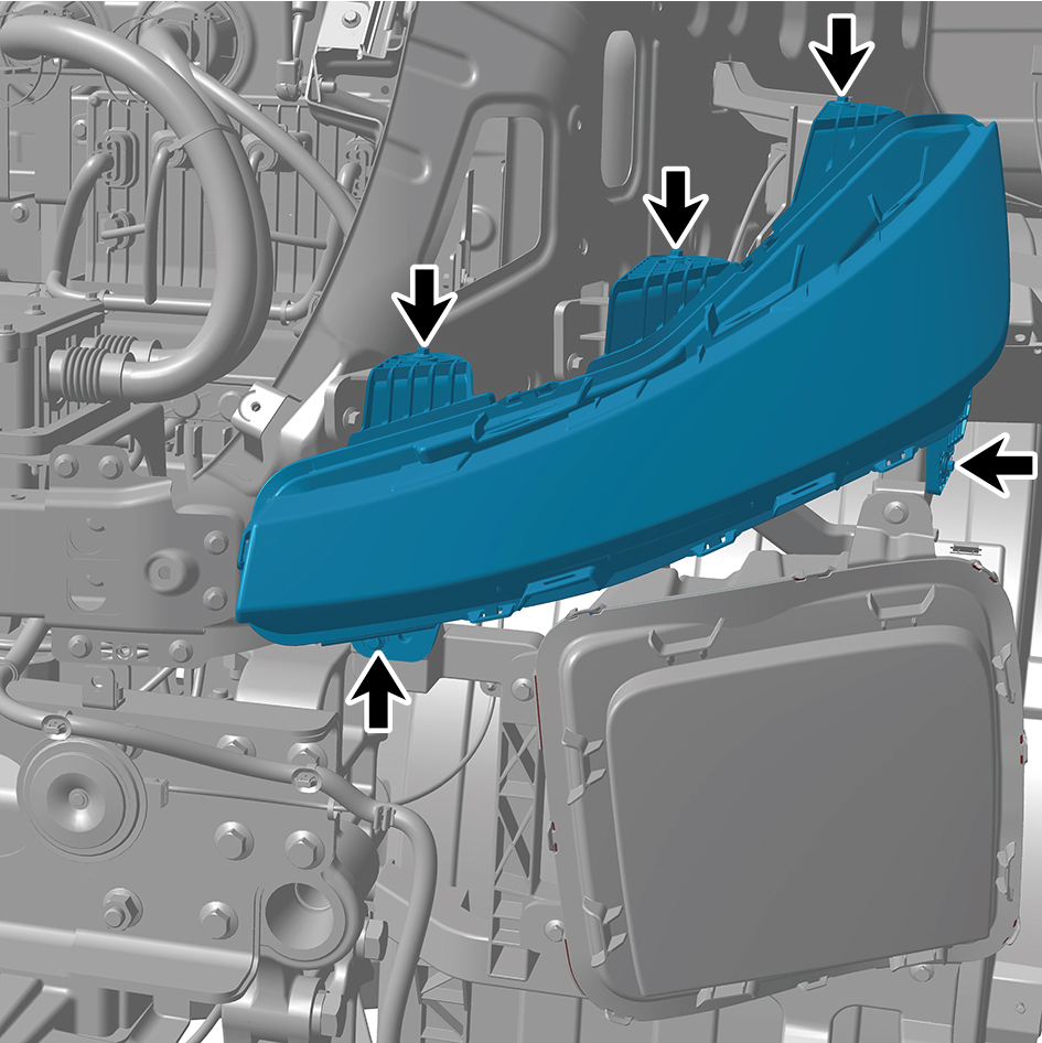
20
Remove the left front combination lamp.
Installation Procedures
1
Move the left front combination lamp to the mounting
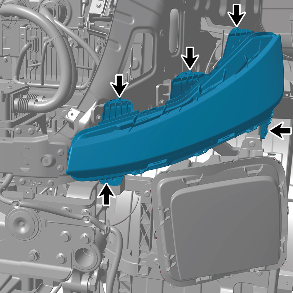
position.
2
Install 5 fixing bolts of the left front combination lamp.
Torque:(6.5 +/- .75) ft lbs
3
Connect 1 harness connector of the left front combination
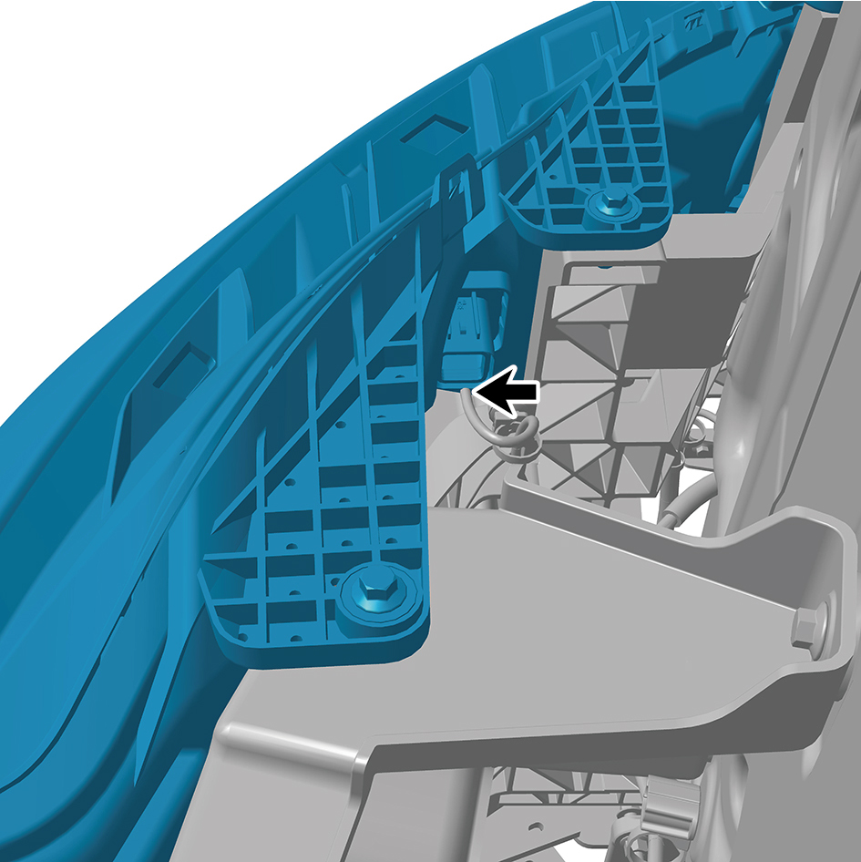
lamp.
caution
The harness is firmly connected following the
principal of "insert until a click is heard for
confirmation".
4
Install the left fender assembly.
5
Install the left fender trim strip.
6
Install the front windshield cover plate assembly.
7
Install the primary wiper arm blade assembly (nozzle and
hose).
8
Install the left front wheel housing body.
9
Install the left physical exterior rearview mirror assembly.
10
Install the front bumper assembly.
11
Install the right cover plate of the corner radar.
12
Install the left cover plate of the corner radar.
13
Install the front MMW radar adapter bracket.
14
Install the forward MMW radar.
15
Install the front MMW radar shield.
16
Install the through-type lamp.
17
Install the engine compartment trim panel body.
18
Connect the battery negative cable.
19
Close the front flip cover plate.
20
Close the door.
7.11.2.5 Replacement of Right Front Combination Lamp
Combination Lamp
Removal Procedures
1
Open the door.
2
Open the front flip cover plate.
3
Disconnect the battery negative cable.
caution
power down the high-voltage system before
disconnecting the negative pole of the storage
battery.
4
Remove the engine compartment trim panel body.
5
Remove the through-type lamp.
6
Remove the front MMW radar shield.
7
Remove the forward MMW radar.
8
Remove the front MMW radar adapter bracket.
9
Remove the left cover plate of the corner radar.
10
Remove the right cover plate of the corner radar.
11
Remove the front bumper assembly.
12
Remove the right triangular cover plate assembly.
13
Remove the right front wheel housing body.
14
Remove the primary wiper arm blade assembly (nozzle
and hose).
15
Remove the front windshield cover plate assembly.
16
Remove the right fender trim strip.
17
Remove the right fender assembly.
18
Disconnect 1 harness connector of the right front
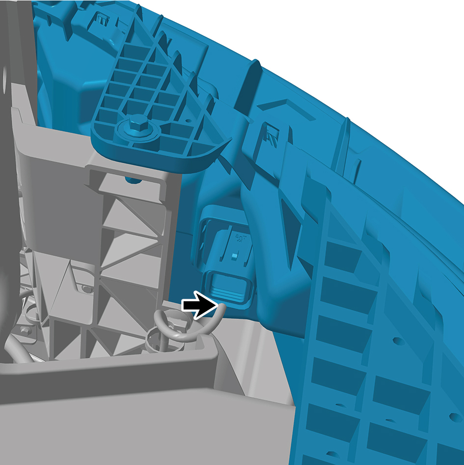
combination lamp.
19
Remove 5 fixing bolts of the right front combination lamp.
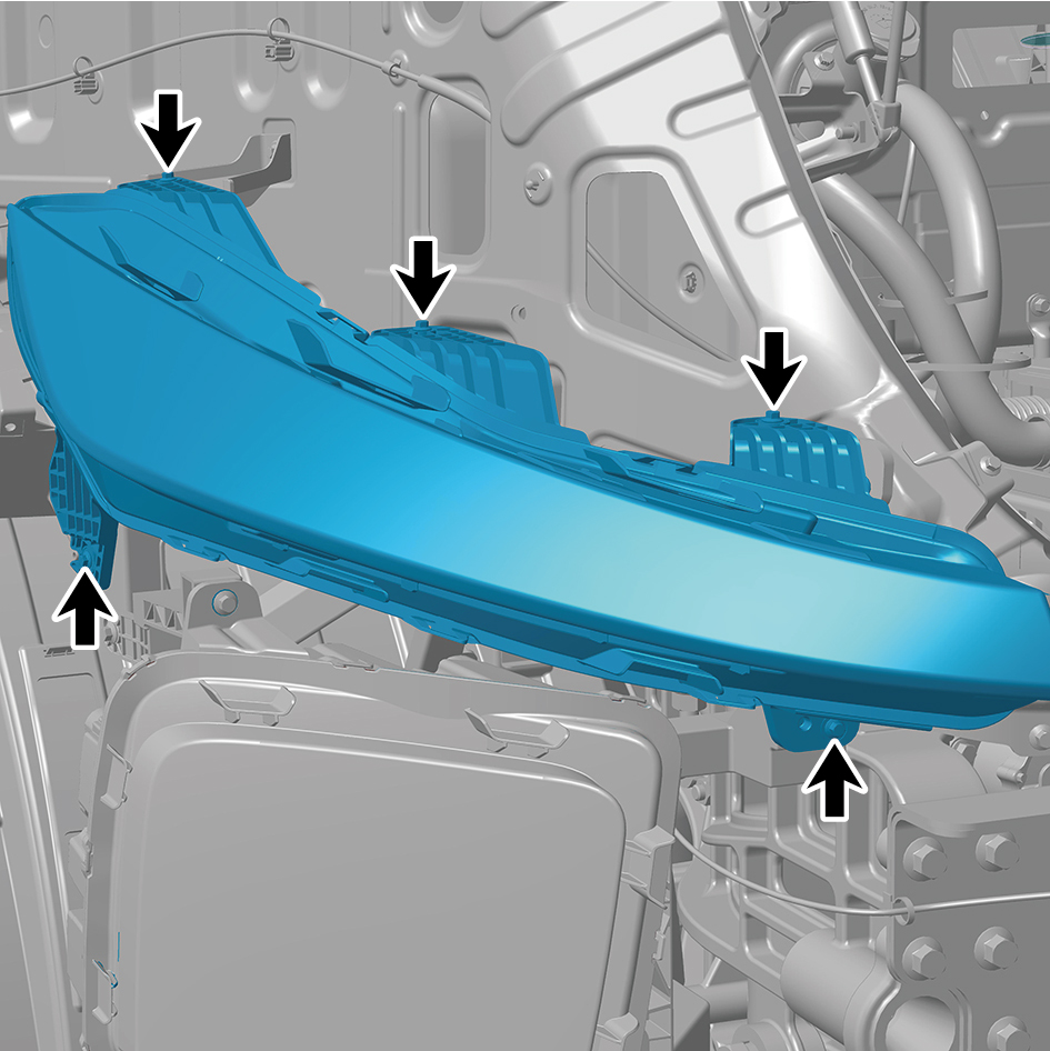
20
Remove the right front combination lamp.
Installation Procedures
1
Move the right front combination lamp to the mounting
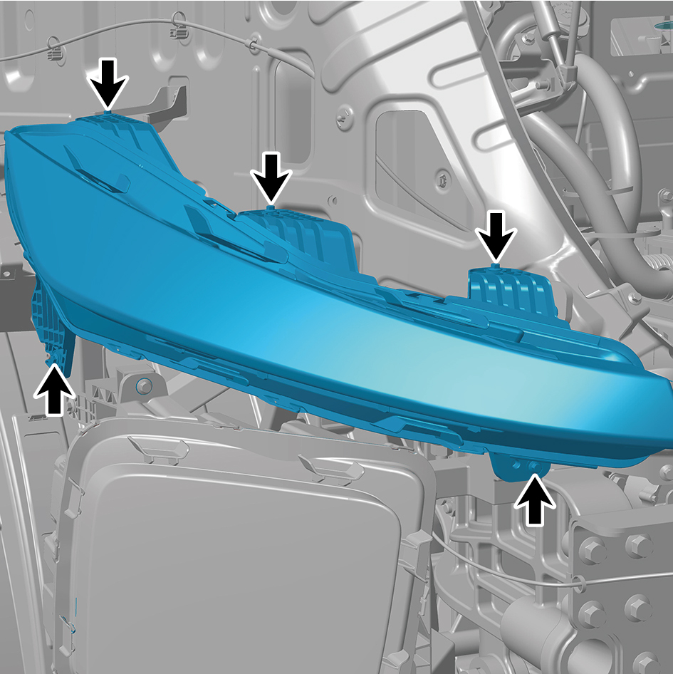
position.
2
Install 5 fixing bolts of the right front combination lamp.
Torque: (6.5 +/- .75) ft lbs
3
Connect 1 harness connector of the right front
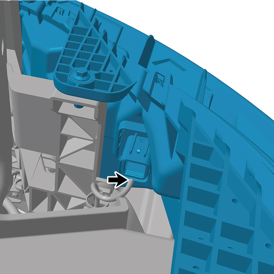
combination lamp.
caution
The harness is firmly connected following the
principal of "insert until a click is heard for
confirmation".
4
Install the right fender assembly.
5
Install the right fender trim strip.
6
Install the front windshield cover plate assembly.
7
Install the primary wiper arm blade assembly (nozzle and
hose).
8
Install the right front wheel housing body.
9
Install the right triangular cover plate assembly.
10
Install the front bumper assembly.
11
Install the right cover plate of the corner radar.
12
Install the left cover plate of the corner radar.
13
Install the front MMW radar adapter bracket.
14
Install the forward MMW radar.
15
Install the front MMW radar shield.
16
Install the through-type lamp.
17
Install the engine compartment trim panel body.
18
Connect the battery negative cable.
19
Close the front flip cover plate.
20
Close the door.
7.11.2.6 Replacement of Left Front End-outline Marker Lamp
Marker Lamp
Removal Procedures
1
Open the door.
2
Open the front flip cover plate.
3
Disconnect the battery negative cable.
caution
power down the high-voltage system before
disconnecting the negative pole of the storage
battery.
4
Remove the left A-pillar protective plate assembly.
5
Remove the right A-pillar protective plate assembly.
6
Remove the sunshade rail assembly.
7
Remove the front camera trim cover assembly.
8
Remove the sunshade cover plate assembly.
9
Remove the left ceiling lamp.
10
Remove the right ceiling lamp.
11
Remove the curtain rail assembly.
12
Remove the middle ceiling assembly.
13
Disconnect 1 harness connector of the left front end-
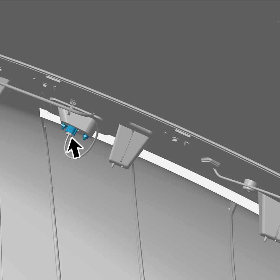
outline marker lamp.
14
Remove 2 fixing nuts of the left front end-outline marker
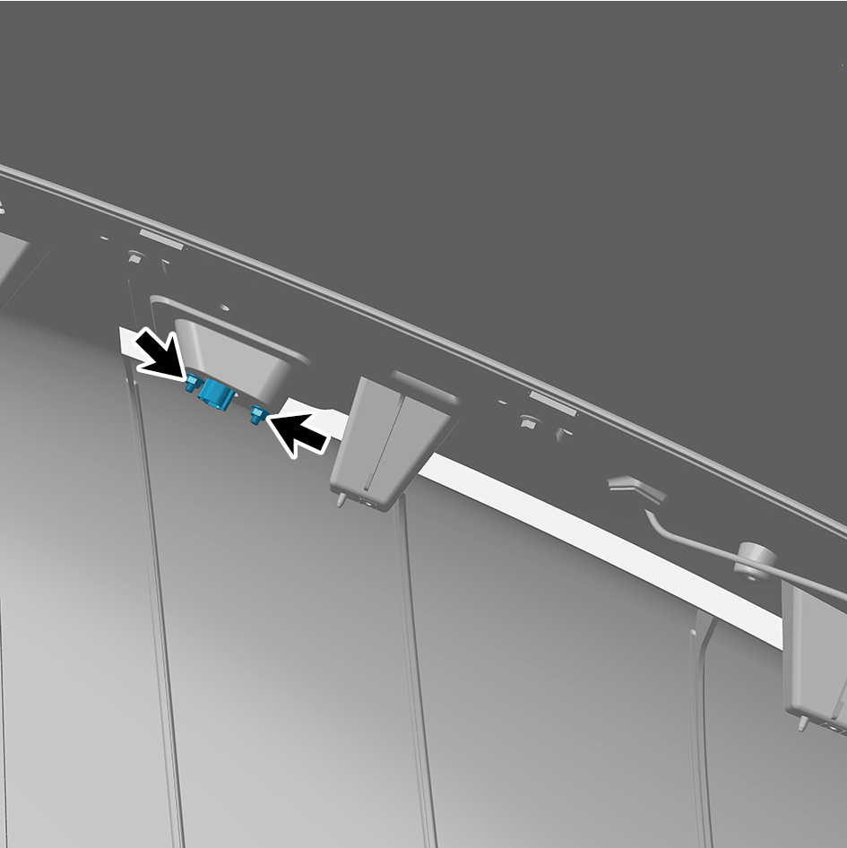
lamp.
15
Remove the left front end-outline marker lamp.
Installation Procedures
1
Move the left front end-outline marker lamp to the
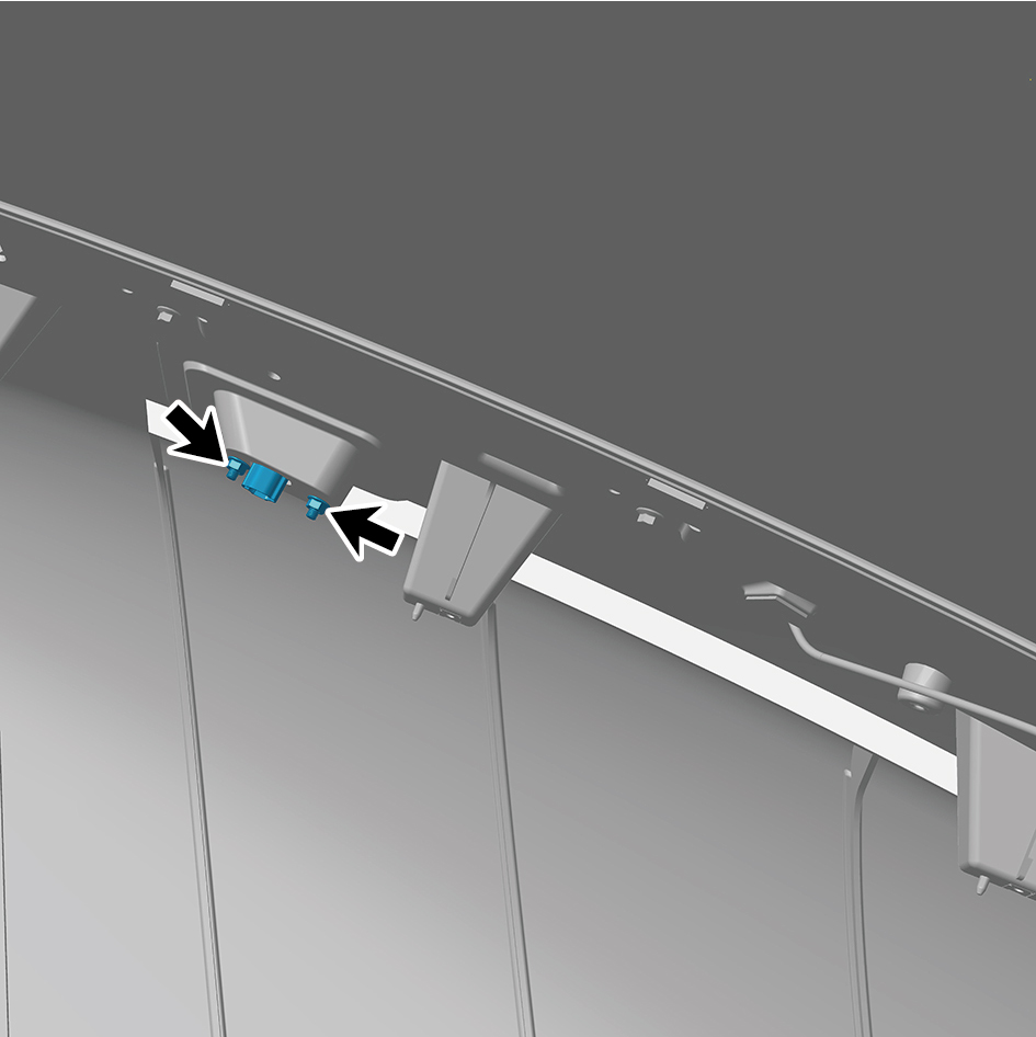
mounting position.
2
Install 2 fixing nuts of the left front end-outline marker
lamp.
Torque:(6.5 +/- .75) ft lbs
3
Connect 1 harness connector of the left front end-outline
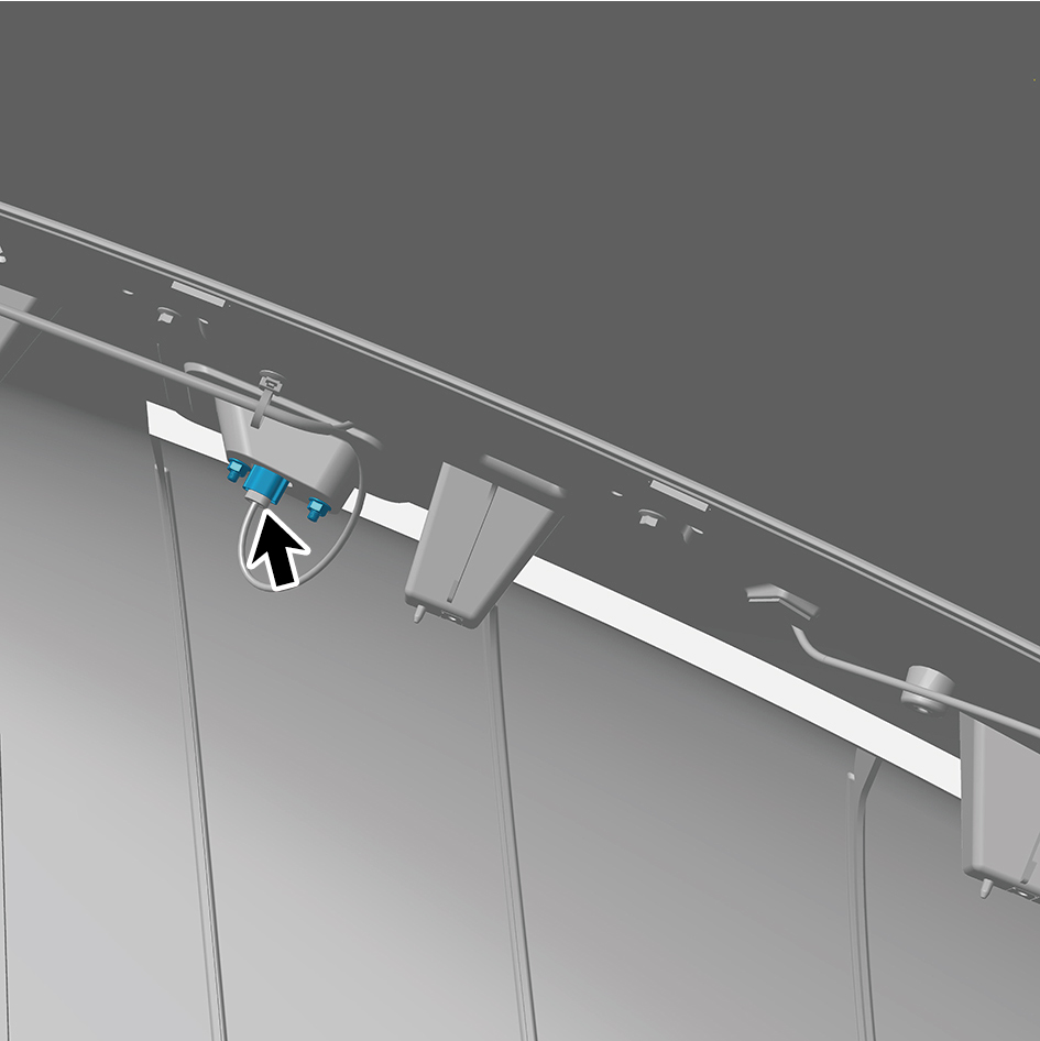
marker lamp.
caution
The harness is firmly connected following the
principal of "insert until a click is heard for
confirmation".
4
Install the middle ceiling assembly.
5
Install the curtain rail assembly.
6
Install the right ceiling lamp.
7
Install the left ceiling lamp.
8
Install the sunshade cover plate assembly.
9
Install the front camera trim cover assembly.
10
Install the sunshade rail assembly.
11
Install the right A-pillar protective plate assembly.
12
Install the left A-pillar protective plate assembly.
13
Connect the battery negative cable.
14
Close the front flip cover plate.
15
Close the door.
7.11.2.7 Replacement of Right Front End-outline Marker Lamp
outline Marker Lamp
Removal Procedures
1
Open the door.
2
Open the front flip cover plate.
3
Disconnect the battery negative cable.
caution
power down the high-voltage system before
disconnecting the negative pole of the storage
battery.
4
Remove the left A-pillar protective plate assembly.
5
Remove the right A-pillar protective plate assembly.
6
Remove the sunshade rail assembly.
7
Remove the front camera trim cover assembly.
8
Remove the sunshade cover plate assembly.
9
Remove the left ceiling lamp.
10
Remove the right ceiling lamp.
11
Remove the curtain rail assembly.
12
Remove the middle ceiling assembly.
13
Disconnect 1 harness connector of the right front end-
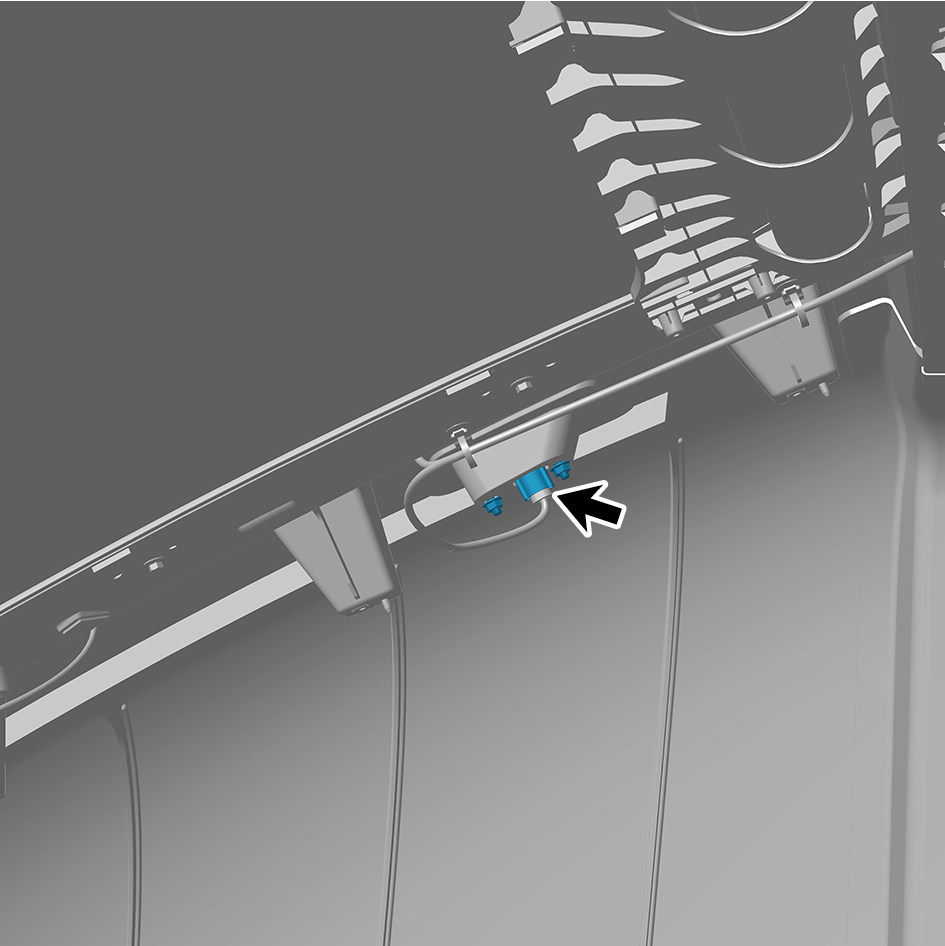
outline marker lamp.
14
Remove 2 fixing nuts of the right front end-outline marker
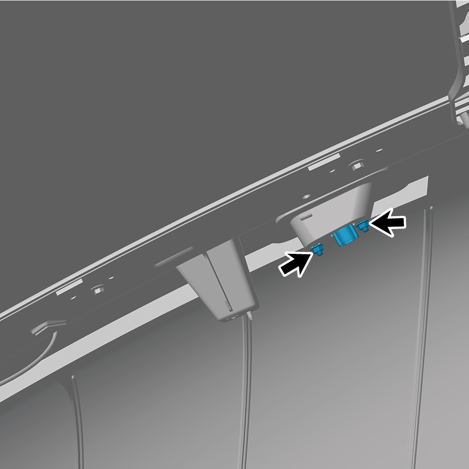
lamp.
15
Remove the right front end-outline marker lamp.
Installation Procedures
1
Move the right front end-outline marker lamp to the
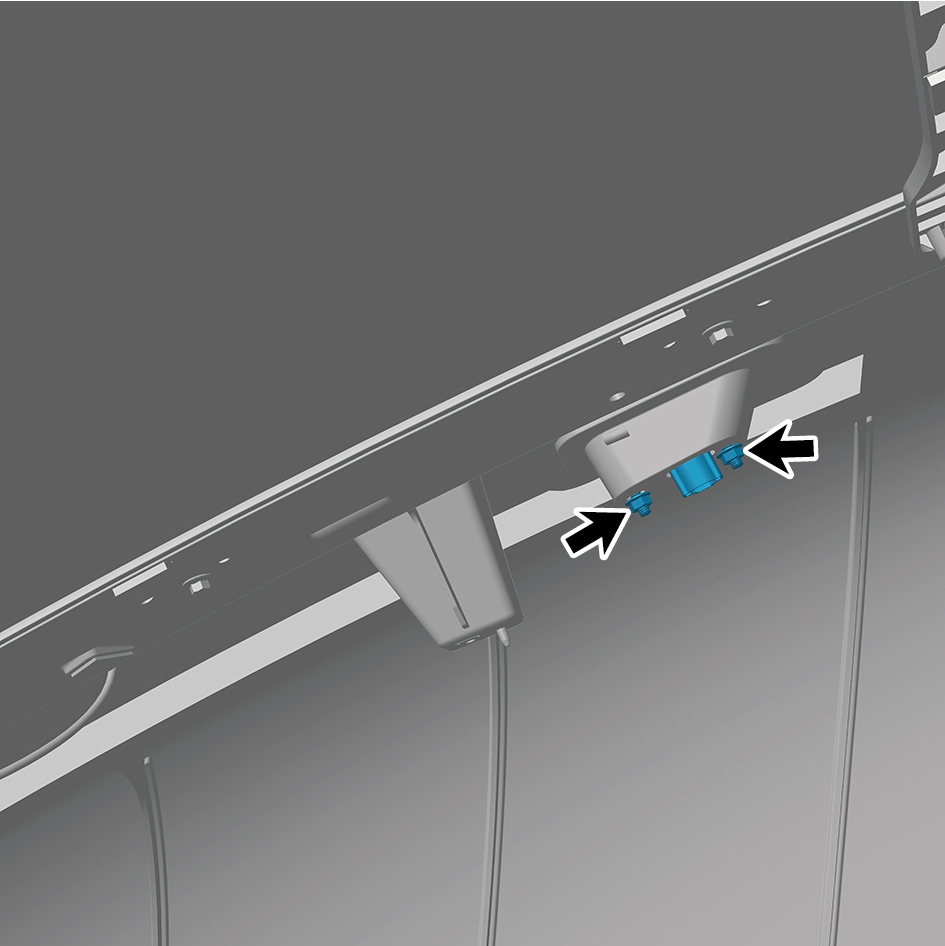
mounting position.
2
Install 2 fixing nuts of the right front end-outline marker
lamp.
Torque:(6.5 +/- .75) ft lbs
3
Connect 1 harness connector of the right front end-outline
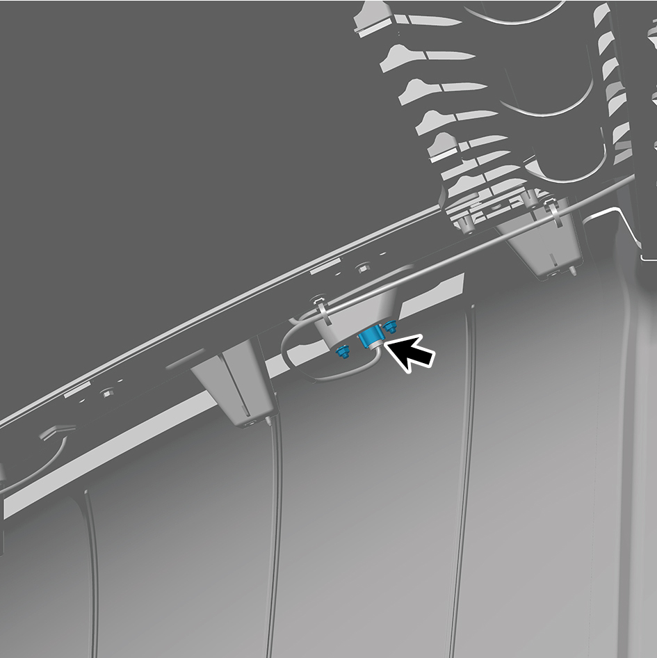
marker lamp.
caution
The harness is firmly connected following the
principal of "insert until a click is heard for
confirmation".
4
Install the middle ceiling assembly.
5
Install the curtain rail assembly.
6
Install the right ceiling lamp.
7
Install the left ceiling lamp.
8
Install the sunshade cover plate assembly.
9
Install the front camera trim cover assembly.
10
Install the sunshade rail assembly.
11
Install the right A-pillar protective plate assembly.
12
Install the left A-pillar protective plate assembly.
13
Connect the battery negative cable.
14
Close the front flip cover plate.
15
Close the door.
7.11.2.8 Identification marker light
Removal Procedures
1
Open the door.
2
Open the front flip cover plate.
3
Disconnect the battery negative cable.
caution
power down the high-voltage system before
disconnecting the negative pole of the storage
battery.
4
Remove the front camera trim cover assembly.
5
Disconnect 1 harness connector of the identification
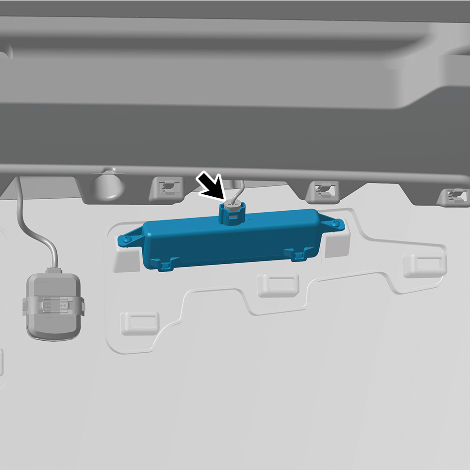
marker light.
6
Remove 2 fixing screws of the identification marker light.
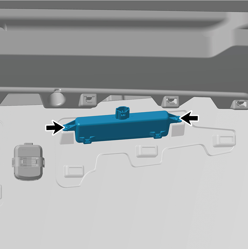
7
Remove the identification marker light.
Installation Procedures
1
Move the identification marker light to the mounting
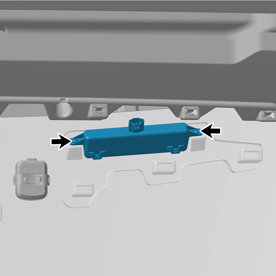
position.
2
Install 2 fixing screws of the identification marker light.
3
Connect 1 harness connector of the identification marker
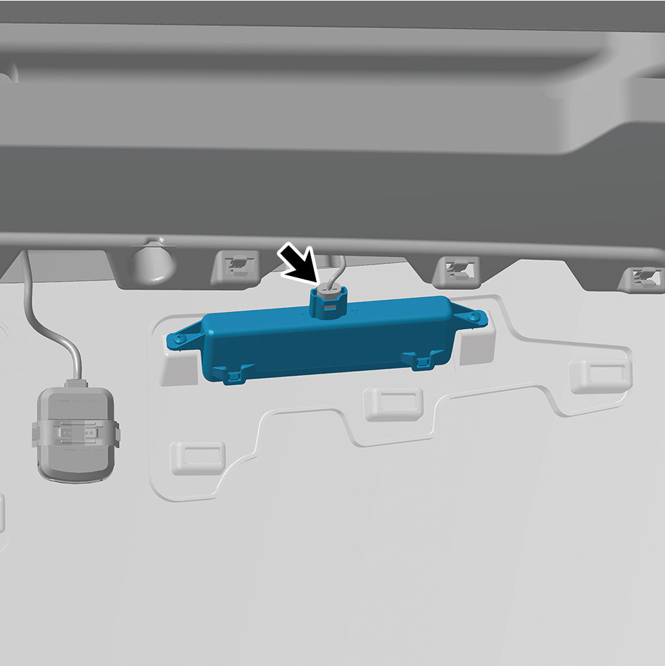
light.
caution
The harness is firmly connected following the
principal of "insert until a click is heard for
confirmation".
4
Install the front camera trim cover assembly.
5
Connect the battery negative cable.
6
Close the front flip cover plate.
7
Close the door.
7.11.2.9 Replacement of Left side Combination Marker Light
Marker Light
Removal Procedures
1
Open the door.
2
Open the front flip cover plate.
3
Disconnect the battery negative cable.
caution
power down the high-voltage system before
disconnecting the negative pole of the storage
battery.
4
Remove the engine compartment trim panel body.
5
Remove the left physical exterior rearview mirror
assembly.
6
Remove the left front wheel housing body.
7
Remove the primary wiper arm blade assembly (nozzle
and hose).
8
Remove the front windshield cover plate assembly.
9
Remove the left fender trim strip.
10
Remove the left fender assembly.
11
Remove 2 fixing bolts of the left side combination marker
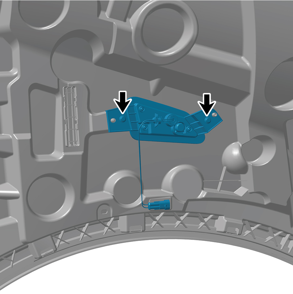
light.
12
Remove the left side combination marker light.
Installation Procedures
1
Move the left side combination marker light to the
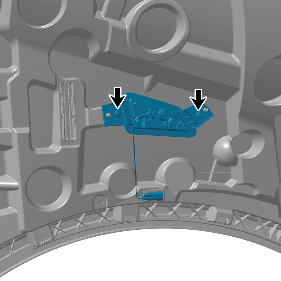
mounting position.
2
Install 2 fixing bolts of the left side combination marker
light.
Torque:(4.5 +/- .75) ft lbs
3
Install the left fender assembly.
4
Install the left fender trim strip.
5
Install the front windshield cover plate assembly.
6
Install the left front wheel housing body.
7
Install the primary wiper arm blade assembly (nozzle and
hose).
8
Install the left physical exterior rearview mirror assembly.
9
Install the engine compartment trim panel body.
10
Connect the battery negative cable.
11
Close the front flip cover plate.
12
Close the door.
7.11.2.10 Replacement of Right Side Combination Marker Light
Combination Marker Light
Removal Procedures
1
Open the door.
2
Open the front flip cover plate.
3
Disconnect the battery negative cable.
caution
power down the high-voltage system before
disconnecting the negative pole of the storage
battery.
4
Remove the engine compartment trim panel body.
5
Remove the right triangular cover plate assembly.
6
Remove the right front wheel housing body.
7
Remove the primary wiper arm blade assembly (nozzle
and hose).
8
Remove the front windshield cover plate assembly.
9
Remove the right fender trim strip.
10
Remove the right fender assembly.
11
Remove 2 fixing bolts of the right side combination marker
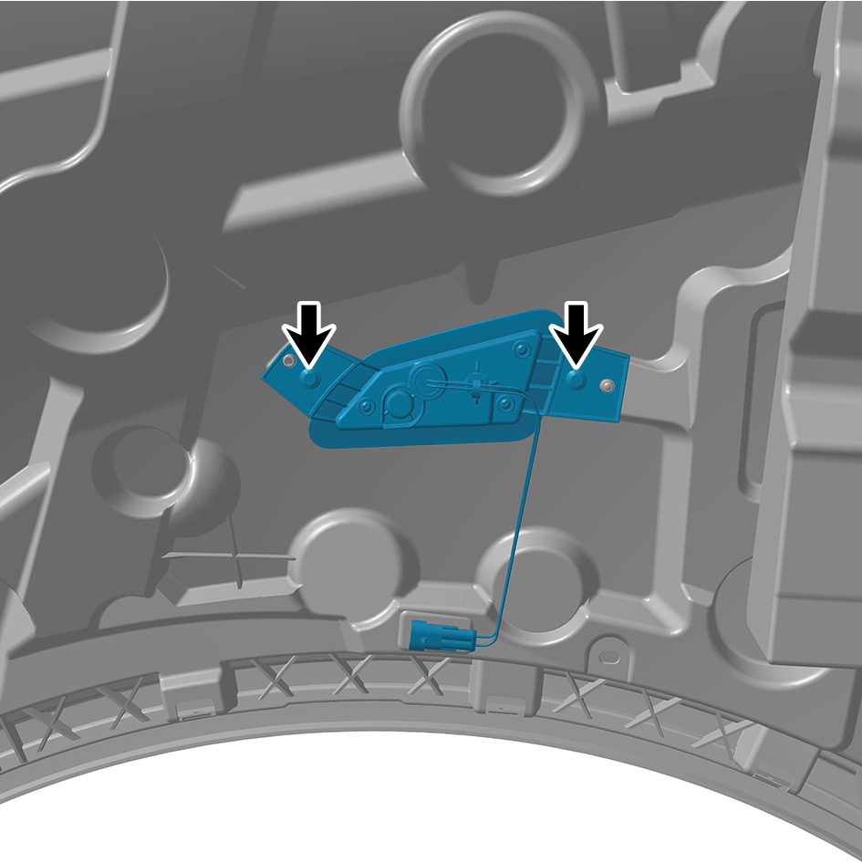
light.
12
Remove the right side combination marker light.
Installation Procedures
1
Move the right side combination marker light to the
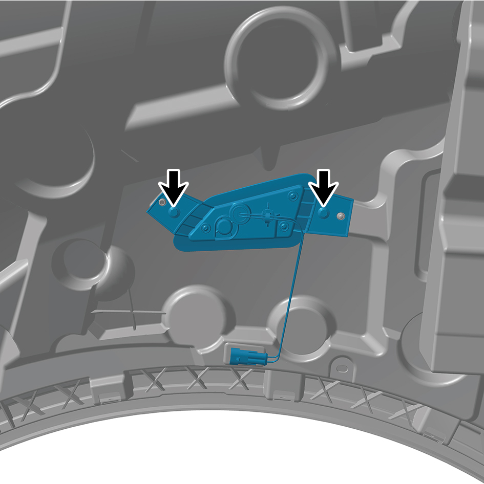
mounting position.
2
Install 2 fixing bolts of the right side combination marker
light.
Torque: (4.5 +/- .75) ft lbs
3
Install the right fender assembly.
4
Install the right fender trim strip.
5
Install the front windshield cover plate assembly.
6
Install the right front wheel housing body.
7
Install the primary wiper arm blade assembly (nozzle and
hose).
8
Install the right triangular cover plate assembly.
9
Install the engine compartment trim panel body.
10
Connect the battery negative cable.
11
Close the front flip cover plate.
12
Close the door.
7.11.2.11 Replacement of Rear Working Lamp
Removal Procedures
1
Open the door.
2
Open the front flip cover plate.
3
Disconnect the battery negative cable.
caution
power down the high-voltage system before
disconnecting the negative pole of the storage
battery.
4
Disconnect 1 harness connector of the rear working lamp.
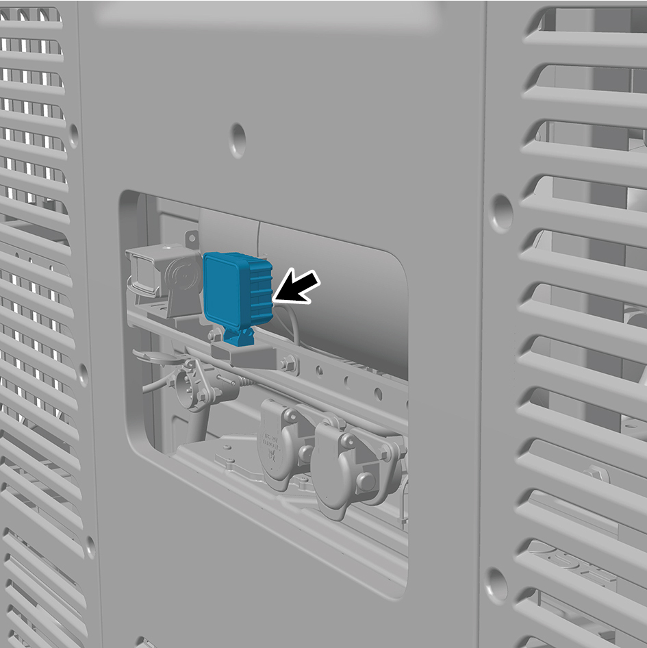
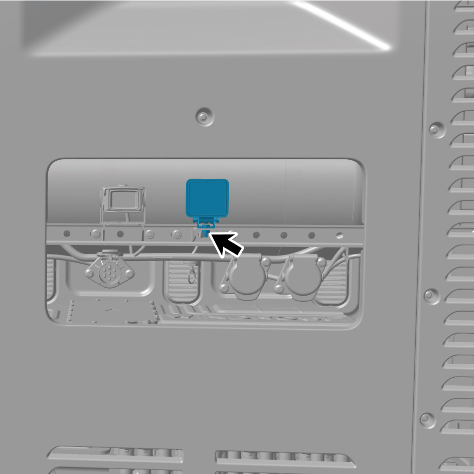
5
Remove 1 fixing bolt of the rear working lamp.
6
Remove the rear working lamp.
Installation Procedures
1
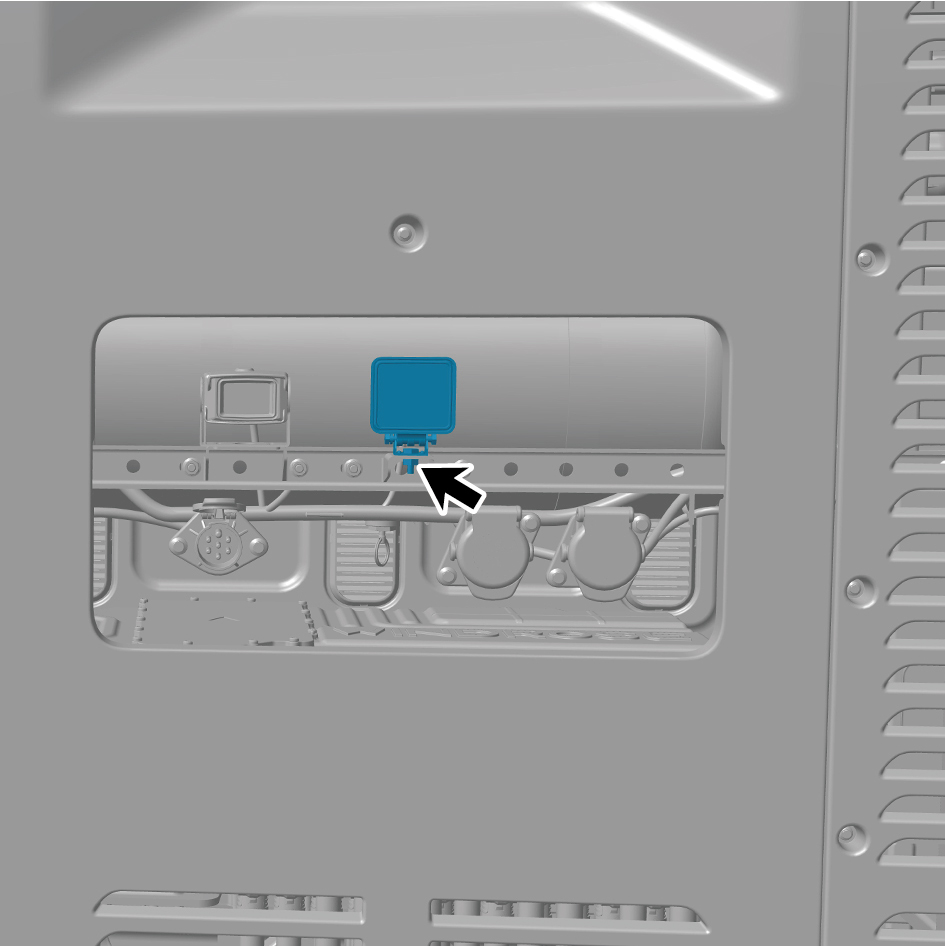
Move the rear working lamp to the mounting position.
2
Install 1 fixing bolt of the rear working lamp.
Torque:(18.5 +/- 2) ft lbs
3
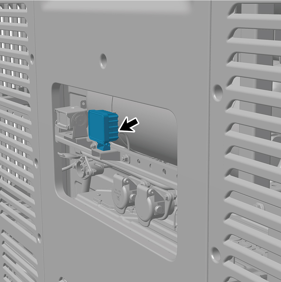
Connect 1 harness connector of the rear working lamp.
caution
The harness is firmly connected following the
principal of "insert until a click is heard for
confirmation".
4
Connect the battery negative cable.
5
Close the front flip cover plate.
6
Close the door.
7.11.2.12 Replacement of Side Marker Combination Lamp (right middle)
Combination Lamp (right middle)
Removal Procedures
1
Open the door.
2
Open the front flip cover plate.
3
Disconnect the battery negative cable.
caution
power down the high-voltage system before
disconnecting the negative pole of the storage
battery.
4
Remove the right side wall lower trim panel assembly.
5
Remove the right skirt plate assembly.
6
Remove the MMWRR.
7
Remove 4 fixing screws of the side marker combination
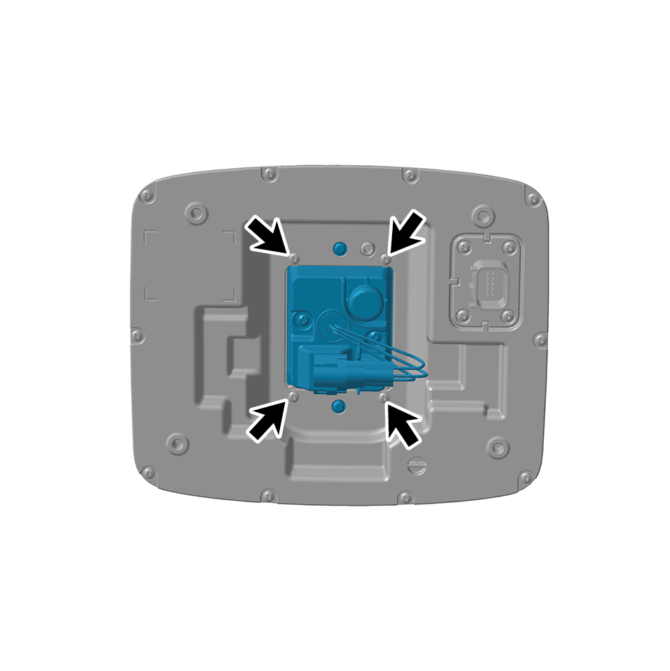
lamp (right middle).
8
Remove the side marker combination lamp (right middle).
Installation Procedures
1
Move the side marker combination lamp (left middle) to
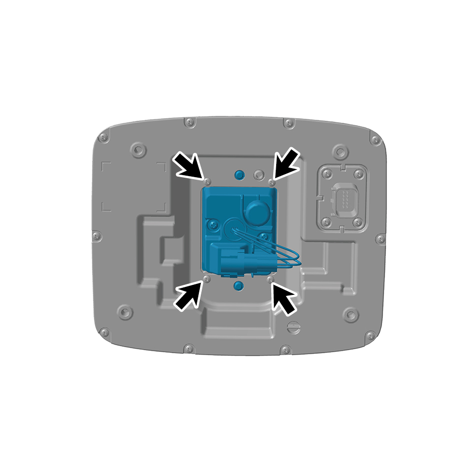
the mounting position.
2
Install 4 fixing screws of the side marker combination lamp
(left middle).
3
Install the MMWRR.
4
Install the right skirt plate assembly.
5
Attach the right side wall lower trim panel assembly.
6
Connect the battery negative cable.
7
Close the front flip cover plate.
8
Close the door.
7.11.2.13 Replacement of Side Marker Combination Lamp (right front)
Combination Lamp (right front)
Removal Procedures
1
Open the door.
2
Open the front flip cover plate.
3
Disconnect the battery negative cable.
caution
power down the high-voltage system before
disconnecting the negative pole of the storage
battery.
4
Remove the right side wall lower trim panel assembly.
5
Remove 2 fixing nuts of the side marker combination lamp
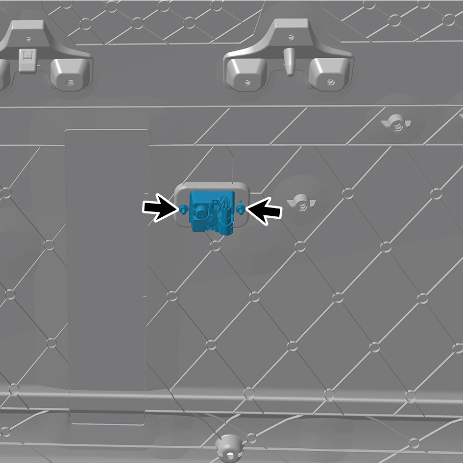
(right front).
6
Remove the side marker combination lamp (right front).
Installation Procedures
1
Move the side marker combination lamp (right front) to the
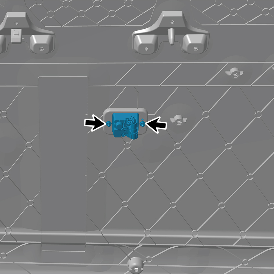
mounting position.
2
Install 2 fixing nuts of the side marker combination lamp
(right front).
Torque: (.4.5 +/- .75) ft lbs
3
Attach the right side wall lower trim panel assembly.
4
Connect the battery negative cable.
5
Close the front flip cover plate.
6
Close the door.
7.11.2.14 Replacement of Side Marker Combination Lamp (right rear)
Combination Lamp (right rear)
Removal Procedures
1
Open the door.
2
Open the front flip cover plate.
3
Disconnect the battery negative cable.
caution
power down the high-voltage system before
disconnecting the negative pole of the storage
battery.
4
Remove the right side wall lower trim panel assembly.
5
Remove the right skirt plate assembly.
6
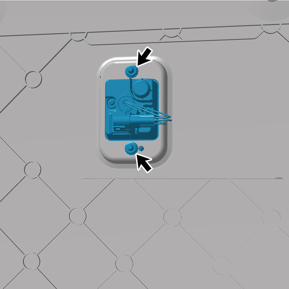
Remove 2 fixing nuts of the side marker combination lamp
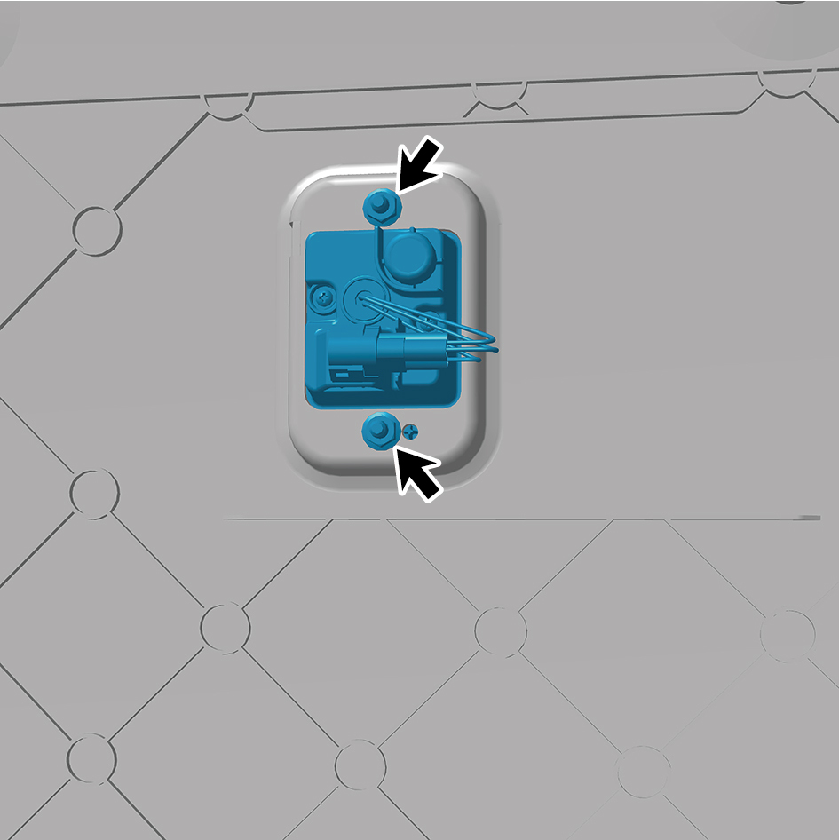
(right rear).
7
Remove the side marker combination lamp (right rear).
Installation Procedures
1
Move the side marker combination lamp (right rear) to the
mounting position.
2
Install 2 fixing nuts of the side marker combination lamp
(right rear).
Torque: (.4.5 +/- .75) ft lbs
3
Install the right skirt plate assembly.
4
Attach the right side wall lower trim panel assembly.
5
Connect the battery negative cable.
6
Close the front flip cover plate.
7
Close the door.
7.11.2.15 Replacement of Side Marker Combination Lamp (left middle)
Combination Lamp (left middle)
Removal Procedures
1
Open the door.
2
Open the front flip cover plate.
3
Disconnect the battery negative cable.
caution
power down the high-voltage system before
disconnecting the negative pole of the storage
battery.
4
Remove the left side wall lower trim panel assembly.
5
Remove the left skirt plate assembly.
6
Remove the MMWRL.
7
Remove 4 fixing screws of the side marker combination
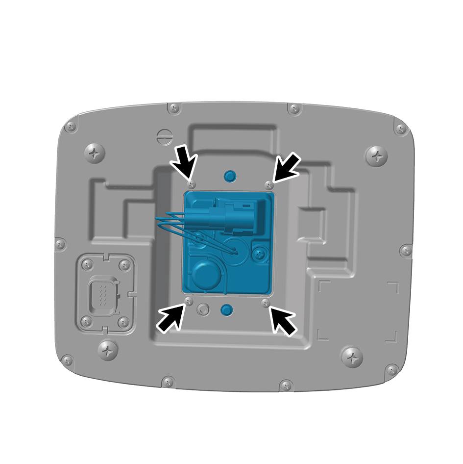
lamp (left middle).
8
Remove the side marker combination lamp (left middle).
Installation Procedures
1
Move the side marker combination lamp (left middle) to
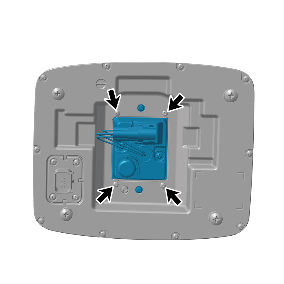
the mounting position.
2
Install 4 fixing screws of the side marker combination lamp
(left middle).
3
Install the MMWRL.
4
Install the left skirt plate assembly.
5
Install the left side wall lower trim panel assembly.
6
Connect the battery negative cable.
7
Close the front flip cover plate.
8
Close the door.
7.11.2.16 Replacement of Side Marker Combination Lamp (left front)
Combination Lamp (left front)
Removal Procedures
1
Open the door.
2
Open the front flip cover plate.
3
Disconnect the battery negative cable.
caution
power down the high-voltage system before
disconnecting the negative pole of the storage
battery.
4
Remove the left side wall lower trim panel assembly.
5
Remove 2 fixing nuts of the side marker combination lamp
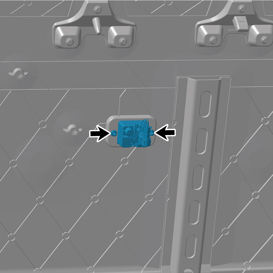
(left front).
6
Remove the side marker combination lamp (left front).
Installation Procedures
1
Move the side marker combination lamp (left front) to the
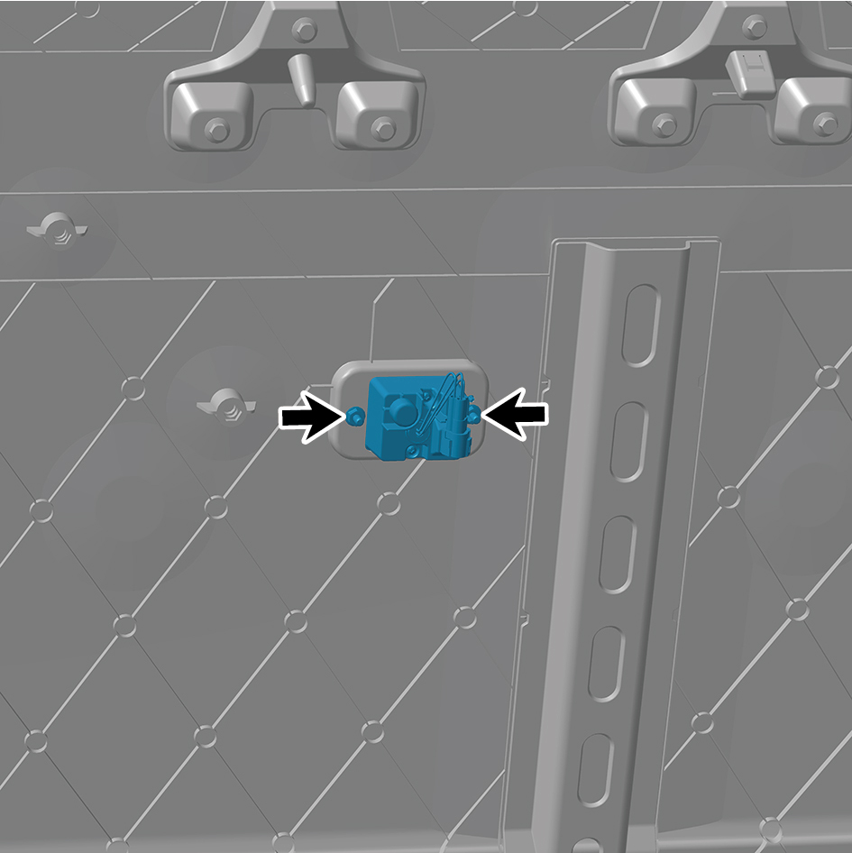
mounting position.
2
Install 2 fixing nuts of the side marker combination lamp
(left front).
Torque: (.4.5 +/- .75) ft lbs
3
Install the left side wall lower trim panel assembly.
4
Connect the battery negative cable.
5
Close the front flip cover plate.
6
Close the door.
7.11.2.17 Replacement of Side Marker Combination Lamp (left rear)
Combination Lamp (left rear)
Removal Procedures
1
Open the door.
2
Open the front flip cover plate.
3
Disconnect the battery negative cable.
caution
power down the high-voltage system before
disconnecting the negative pole of the storage
battery.
4
Remove the left side wall lower trim panel assembly.
5
Remove the left skirt plate assembly.
6
Remove 2 fixing nuts of the side marker combination lamp
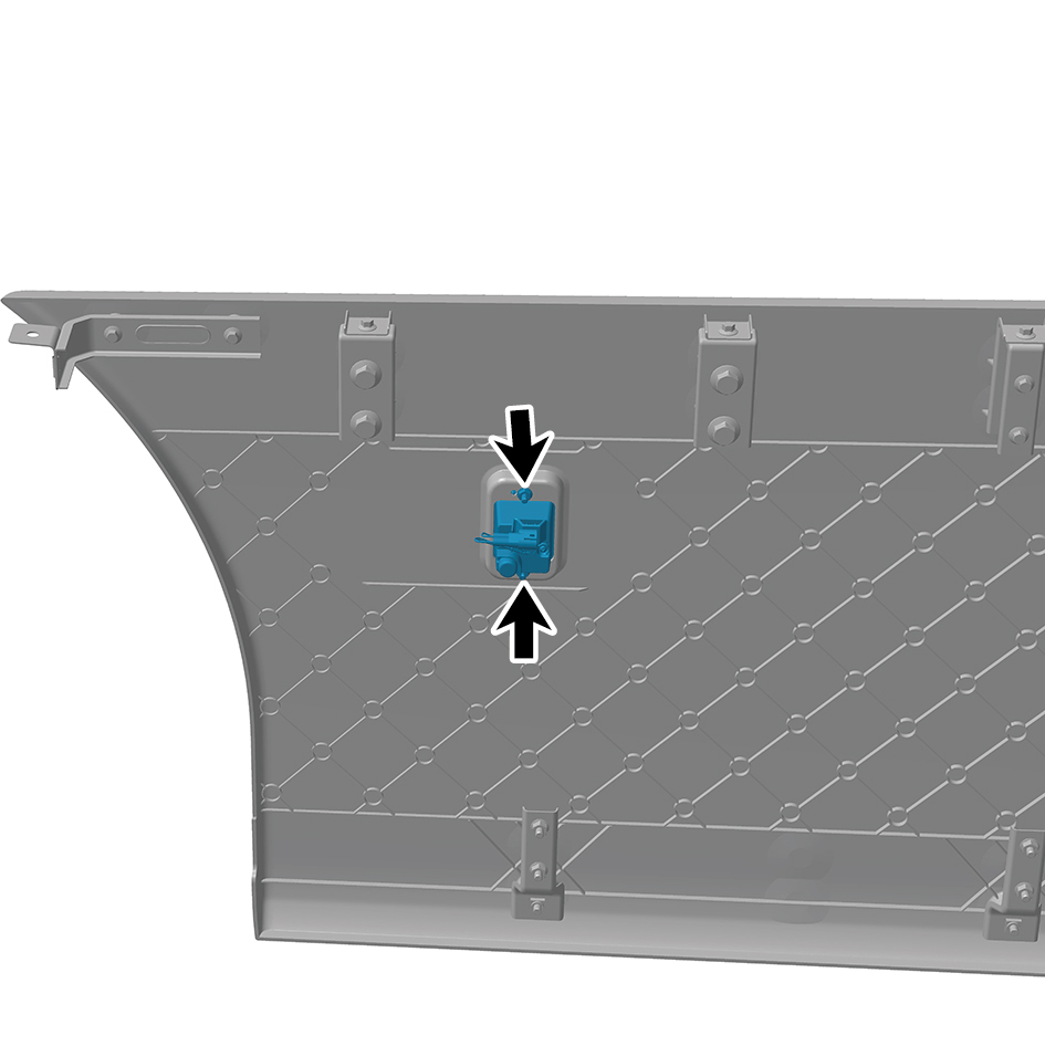
(left rear).
7
Remove the side marker combination lamp (left rear).
Installation Procedures
1
Move the side marker combination lamp (left rear) to the
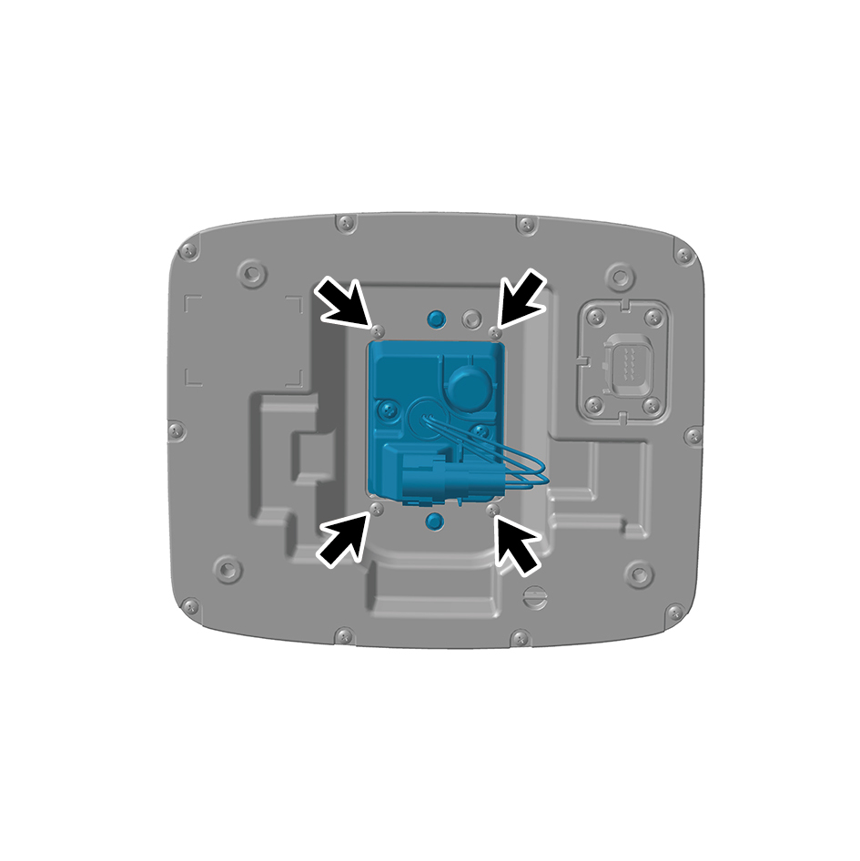
mounting position.
2
Install 2 fixing nuts of the side marker combination lamp
(left rear).
Torque: (.4.5 +/- .75) ft lbs
3
Install the left skirt plate assembly.
4
Install the left side wall lower trim panel assembly.
5
Connect the battery negative cable.
6
Close the front flip cover plate.
7
Close the door.
7.11.2.18 Replacement of Reversing Lamp
Removal Procedures
1
Release air pressure from the brake system.
2
Open the door.
3
Open the front flip cover plate.
4
Disconnect the battery negative cable.
caution
power down the high-voltage system before
disconnecting the negative pole of the storage
battery.
5
Remove the air reservoir assembly (rear upper).
6
Disconnect 2 harness connectors of the reversing lamp.
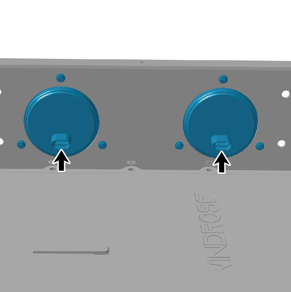
7
Remove 6 fixing nuts of the reversing lamp.
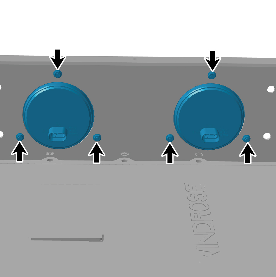
8
Remove the reversing lamp.
Installation Procedures
1
Move the reversing lamp to the mounting position.
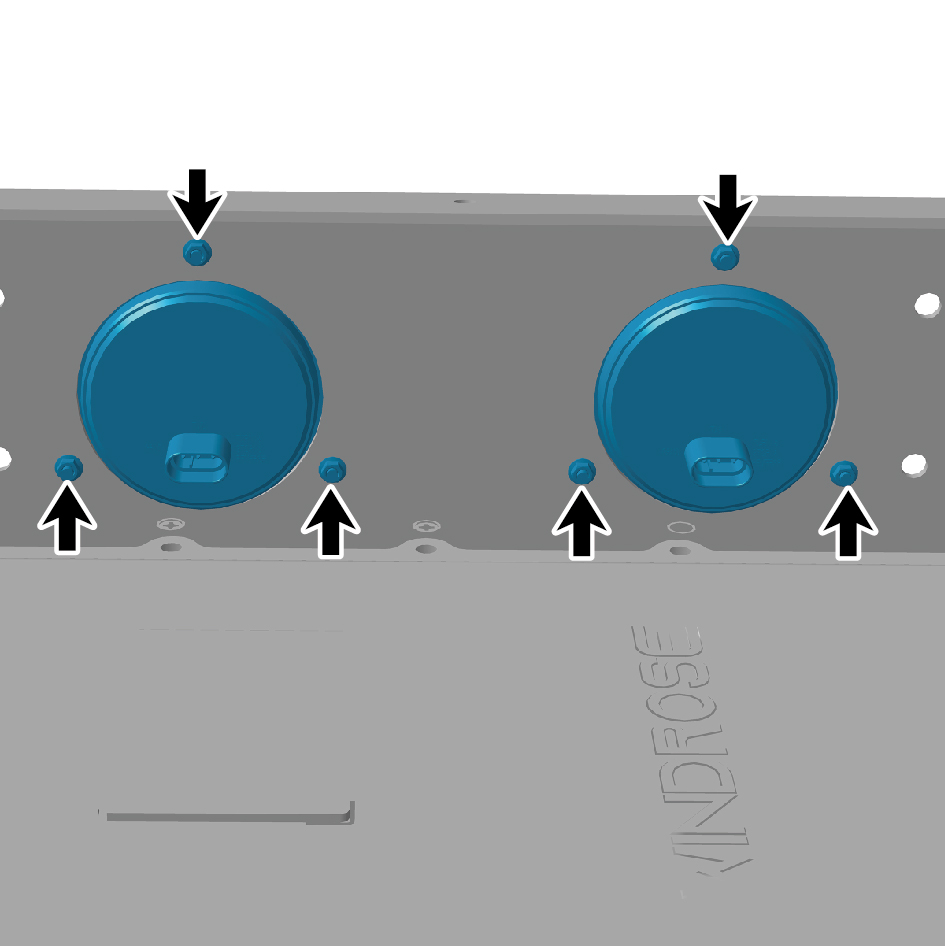
2
Install 6 fixing nuts of the reversing lamp.
3
Connect 2 harness connectors of the reversing lamp.
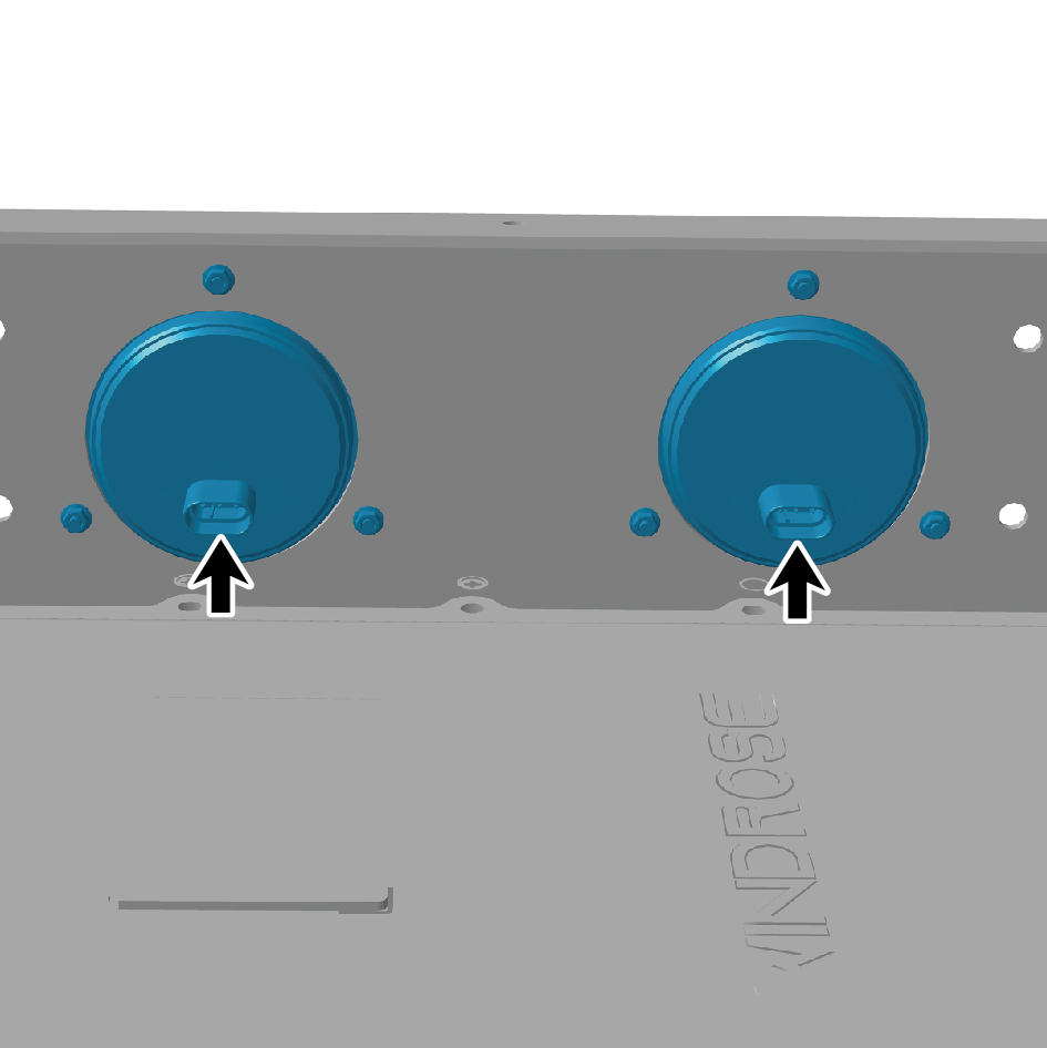
caution
The harness is firmly connected following the
principal of "insert until a click is heard for
confirmation".
4
Install the air reservoir assembly (rear upper).
5
Connect the battery negative cable.
6
Close the front flip cover plate.
7
Close the door.
7.11.2.19 Replacement of the License Plate Light
Light
Disassembly Procedure
1
Open the car door.
2
Open the front flip cover plate.
3
Disconnect the negative battery cable.
4
Disconnect one wire harness connector of the license
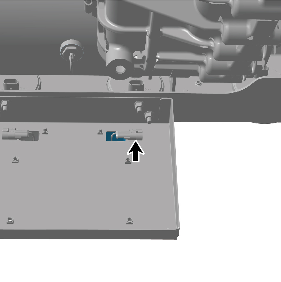
plate light.
5
Remove the two fixing screws of the license plate light.
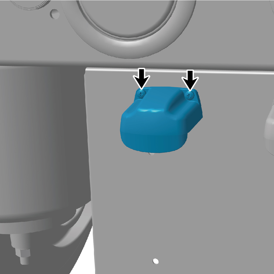
6
Take down the license plate light.
Installation Procedure
1
Install the license plate light.
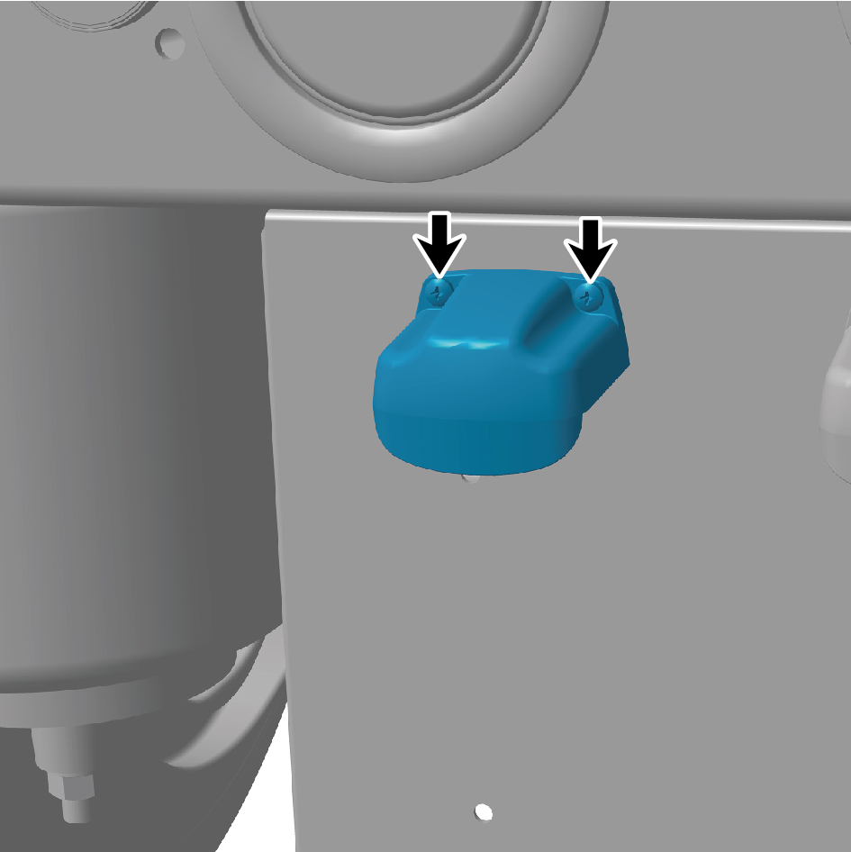
2
Install the two fixing screws of the license plate light.
3
Connect one wire harness connector of the license plate
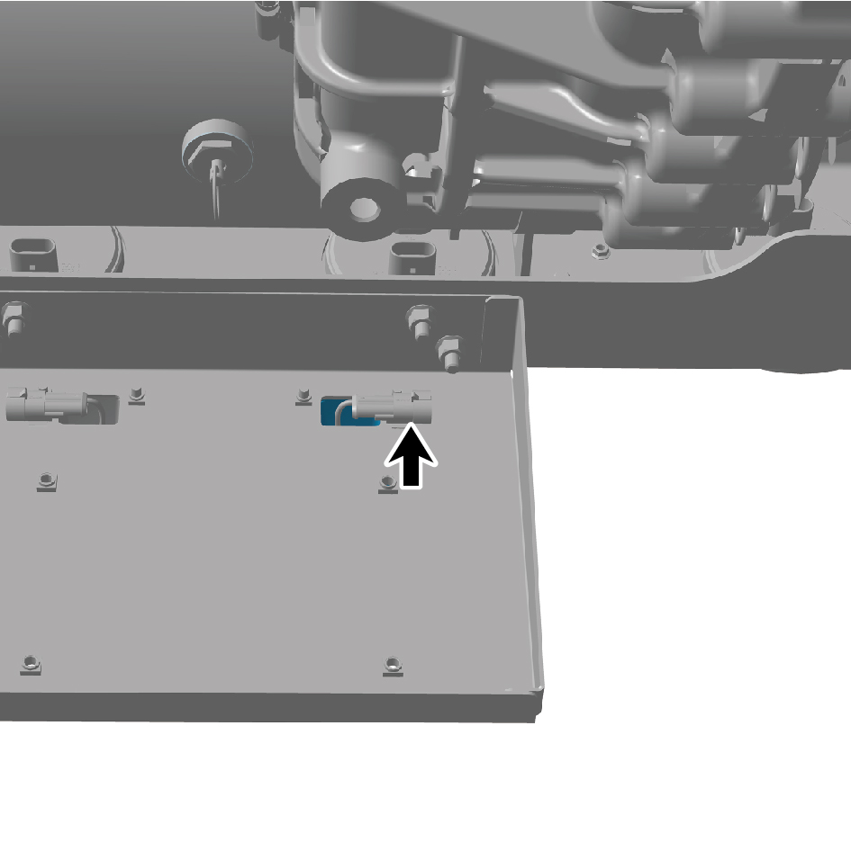
light.
4
Connect the negative cable of the storage battery.
5
Close the front flip cover panel.
6
Close the car door.
7.11.2.20 Replacement of Left Rear Combination Lamp
Combination Lamp
Removal Procedures
1
Release air pressure from the brake system.
2
Open the door.
3
Open the front flip cover plate.
4
Disconnect the battery negative cable.
caution
power down the high-voltage system before
disconnecting the negative pole of the storage
battery.
5
Remove the air reservoir assembly (rear upper).
6
Disconnect 1 harness connector of the left rear
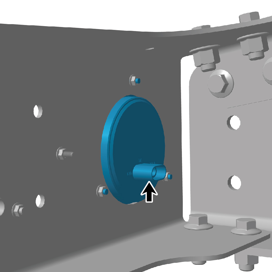
combination lamp.
7
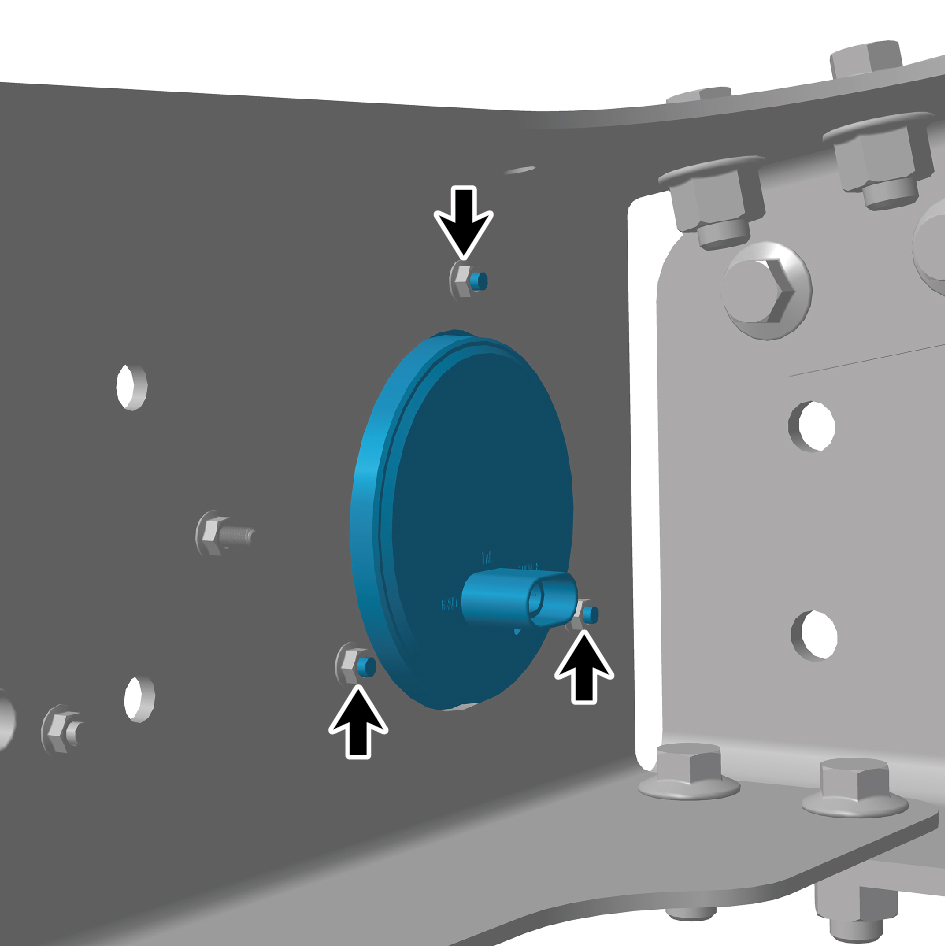
Remove 3 fixing nuts of the left rear combination lamp.
8
Remove the left rear combination lamp.
Installation Procedures
1
Move the left rear combination lamp to the mounting
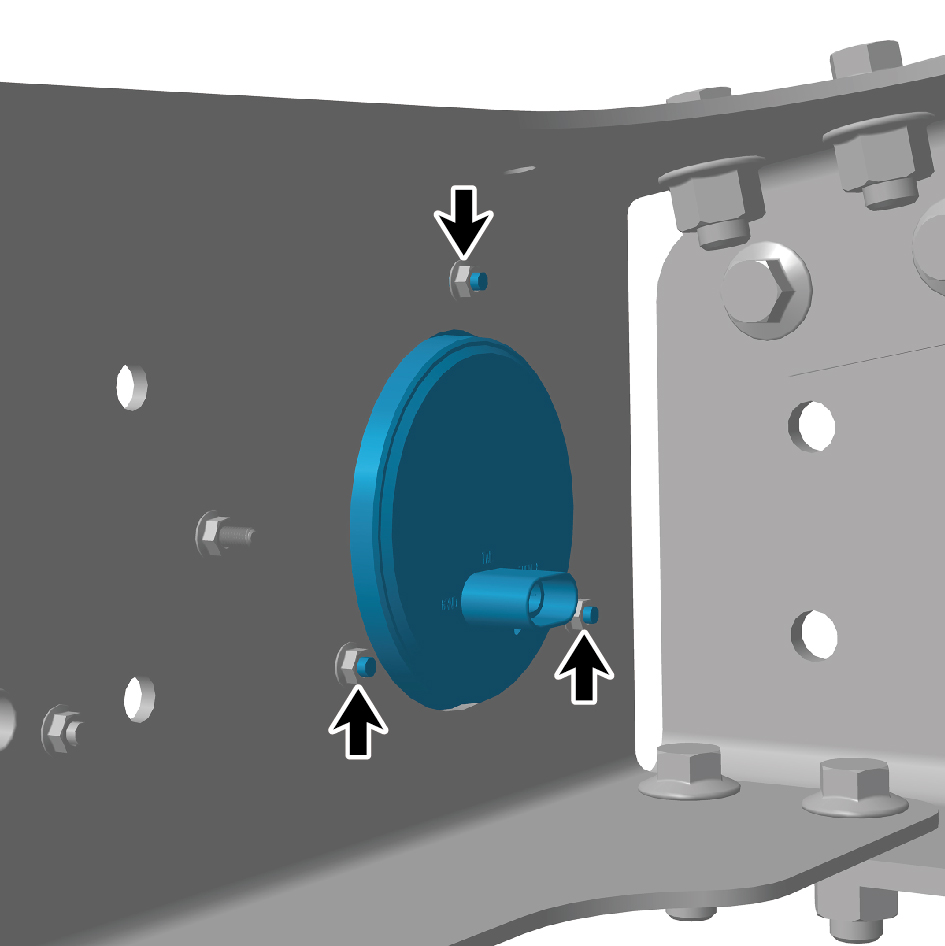
position.
2
Install 3 fixing nuts of the left rear combination lamp.
Torque: (18.5 +/- 2) ft lbs
3
Connect 1 harness connector of the left rear combination
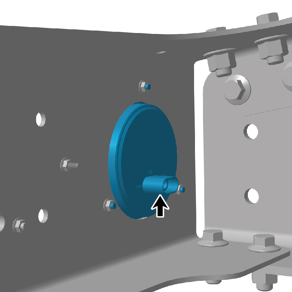
lamp.
caution
The harness is firmly connected following the
principal of "insert until a click is heard for
confirmation".
4
Install the air reservoir assembly (rear upper).
5
Connect the battery negative cable.
6
Close the front flip cover plate.
7
Close the door.
7.11.2.21 Replacement of Right Rear Combination Lamp
Combination Lamp
Removal Procedures
1
Release air pressure from the brake system.
2
Open the door.
3
Open the front flip cover plate.
4
Disconnect the battery negative cable.
caution
power down the high-voltage system before
disconnecting the negative pole of the storage
battery.
5
Remove the air reservoir assembly (rear upper).
6
Disconnect 1 harness connector of the right rear
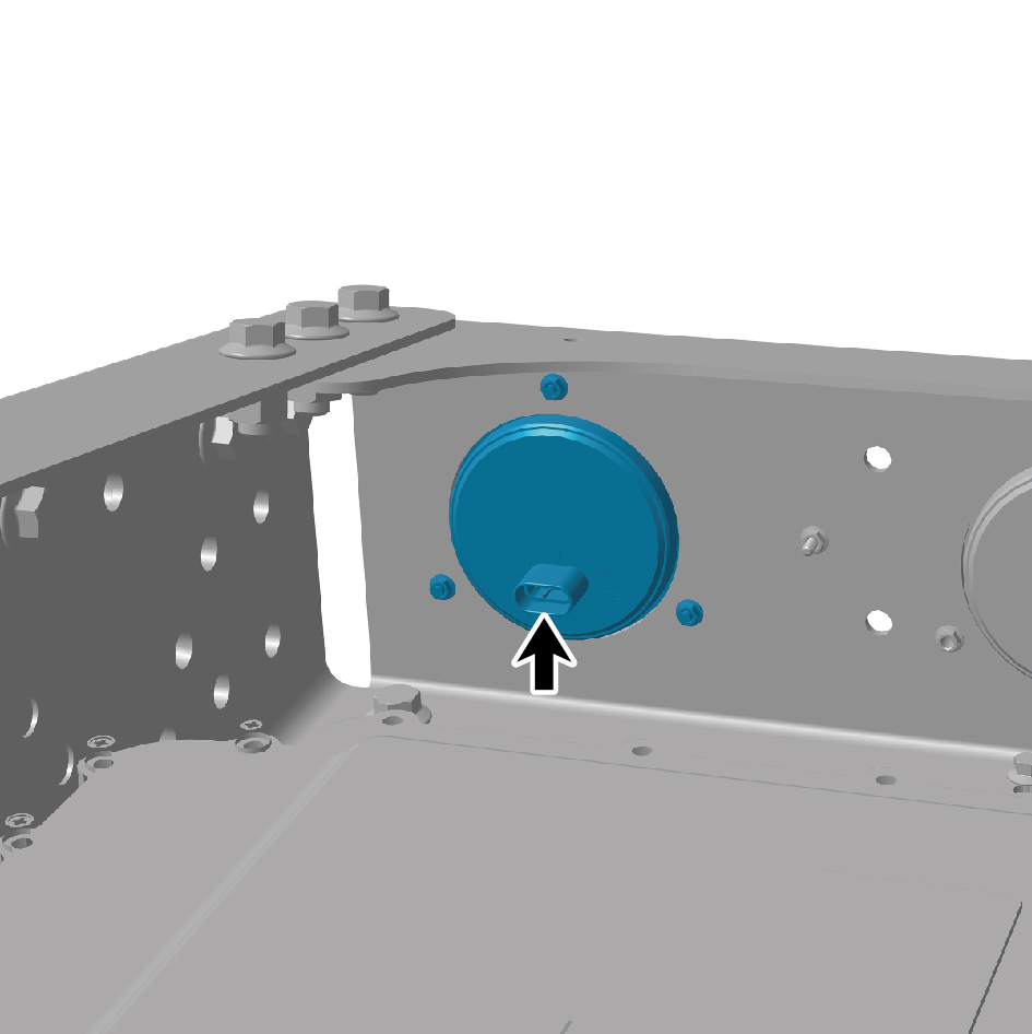
combination lamp.
7
Remove 3 fixing nuts of the right rear combination lamp.
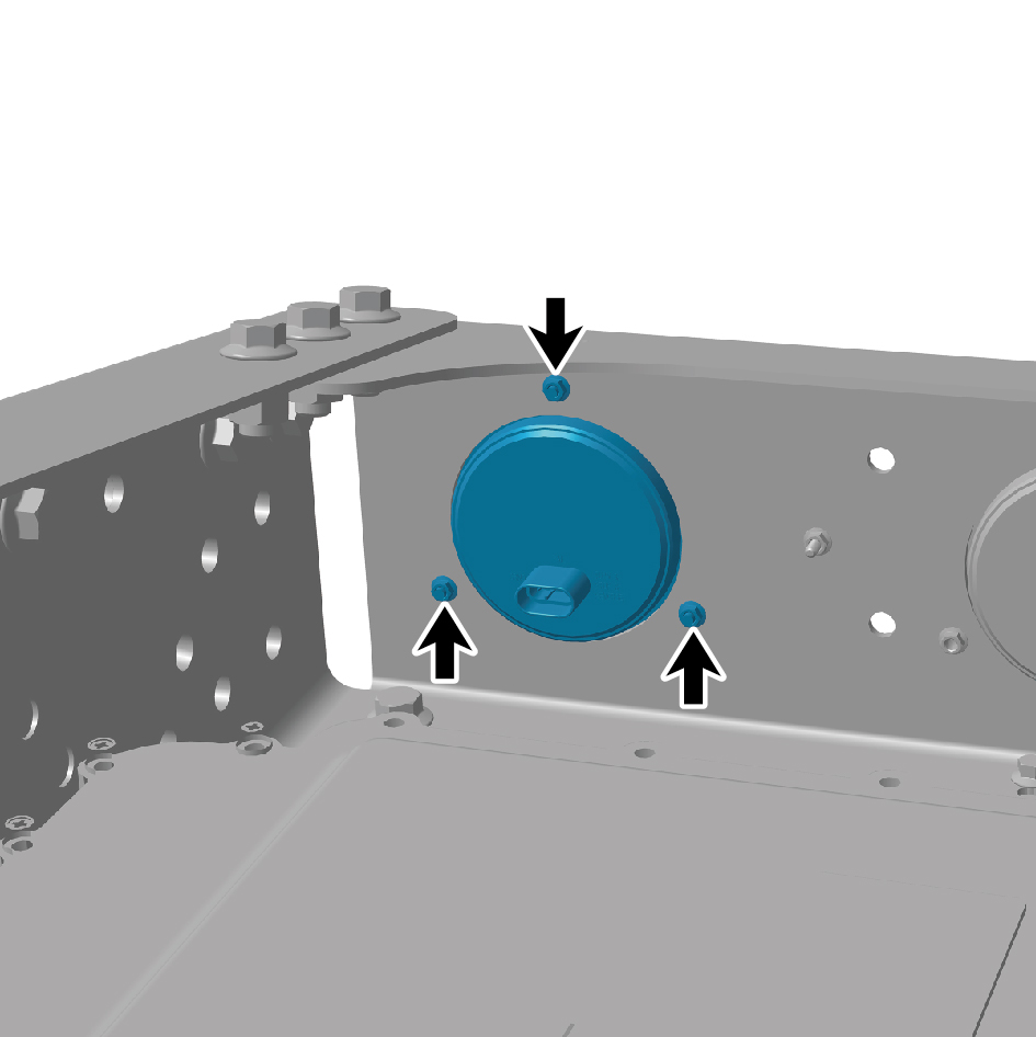
8
Remove the right rear combination lamp.
Installation Procedures
1
Move the right rear combination lamp to the mounting
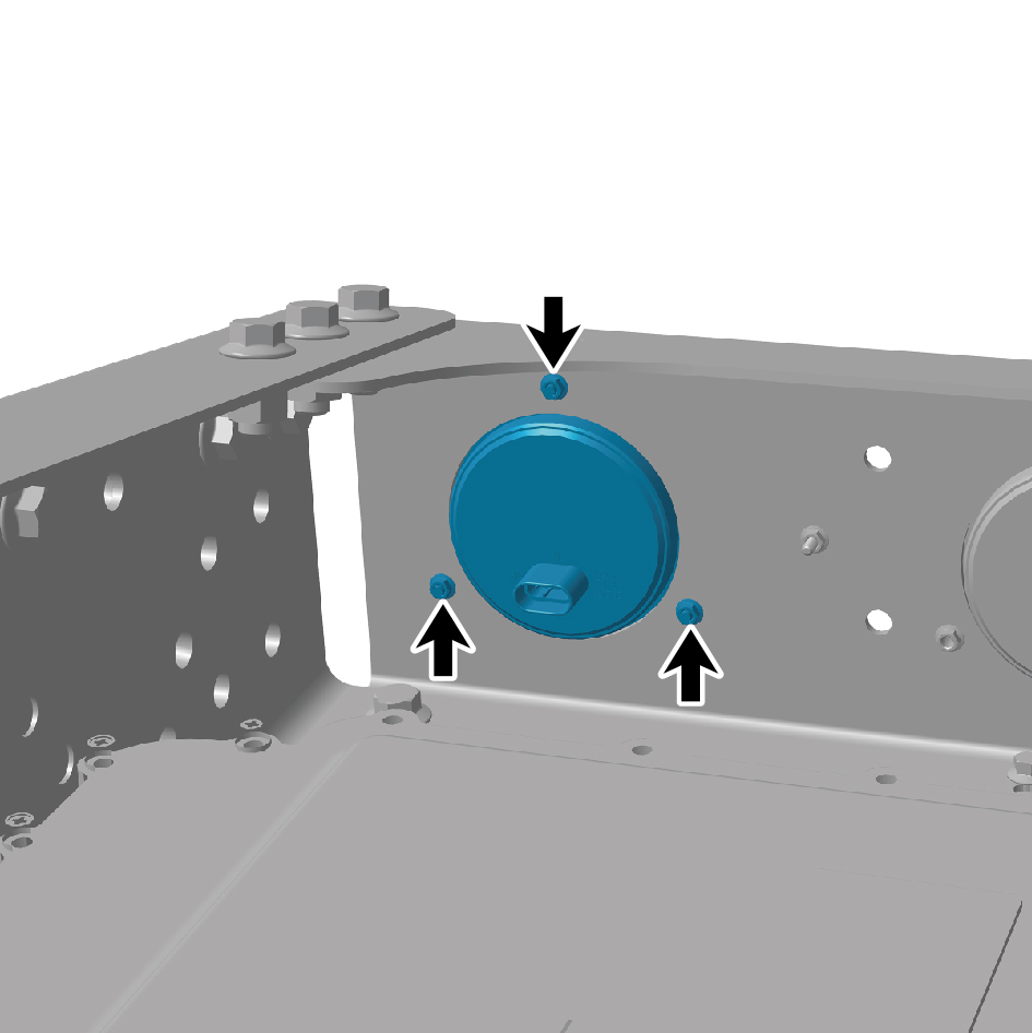
position.
2
Install 3 fixing nuts of the right rear combination lamp.
3
Connect 1 harness connector of the right rear
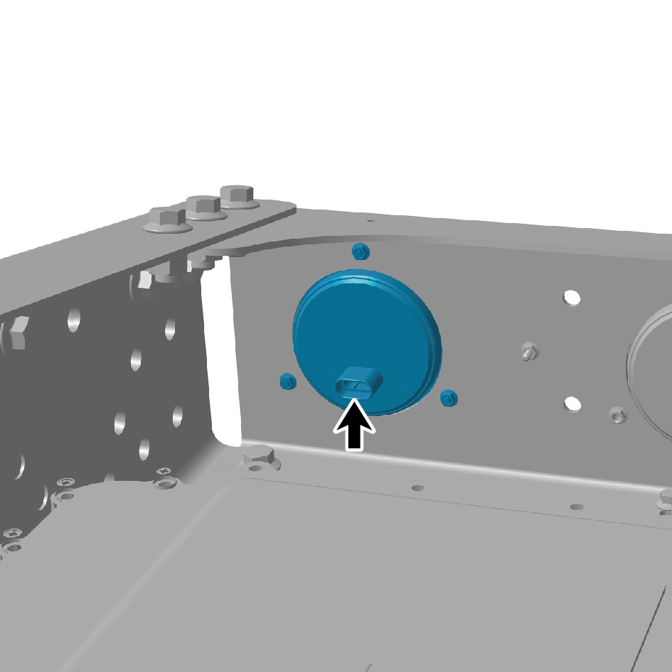
combination lamp.
caution
The harness is firmly connected following the
principal of "insert until a click is heard for
confirmation".
4
Install the air reservoir assembly (rear upper).
5
Connect the battery negative cable.
6
Close the front flip cover plate.
7
Close the door.
7.11.2.22 Replacement of Rear Retro-reflector
Removal Procedures
1
Release air pressure from the brake system.
2
Remove the air reservoir assembly (rear upper).
3
Remove 1 fixing nut of the rear retro-reflector.
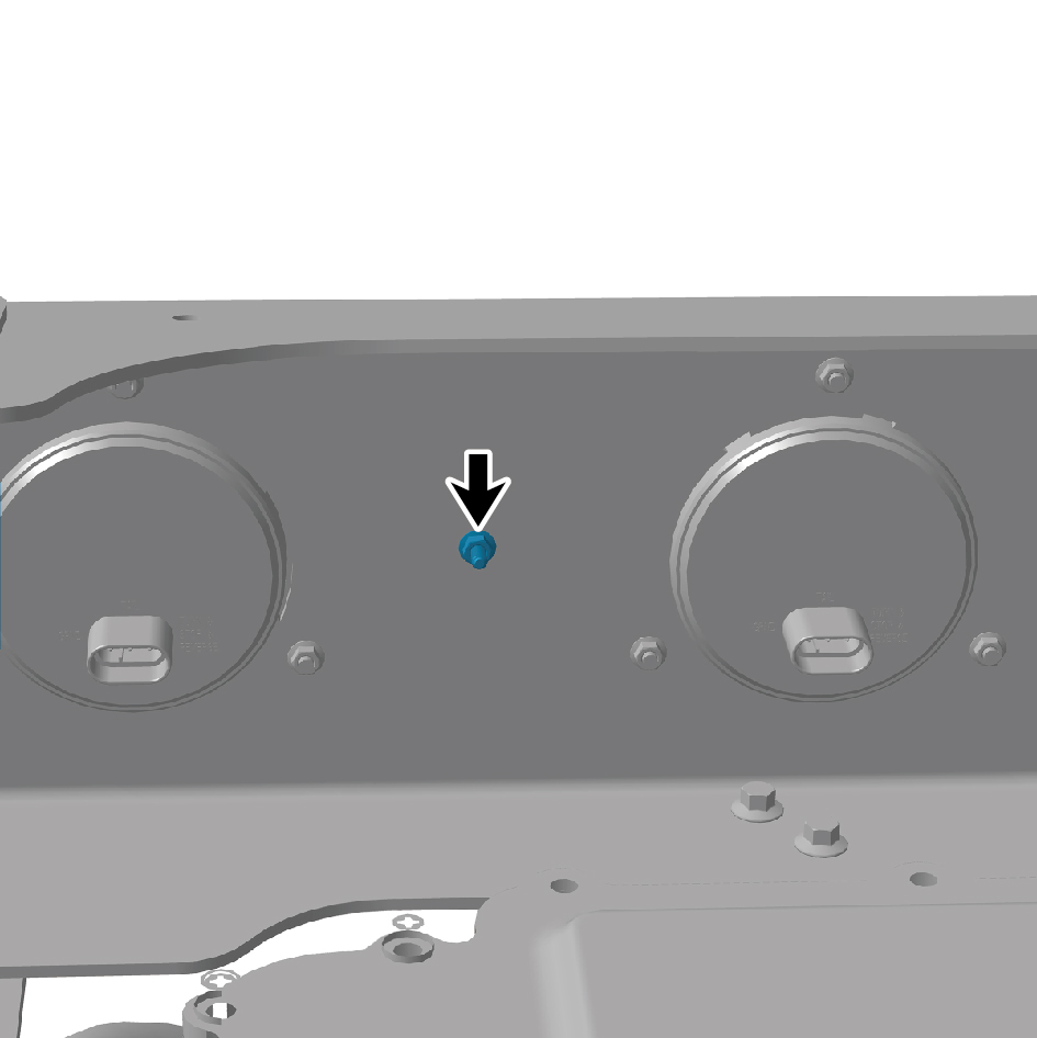
4
Remove the rear retro-reflector.
Installation Procedures
1
Move the rear retro-reflector to the mounting position.
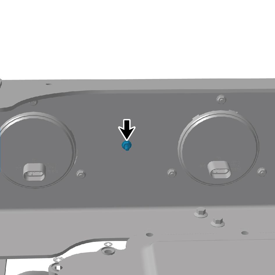
2
Install 1 fixing nut of the rear retro-reflector.
3
Install the air reservoir assembly (rear upper).