← Back to Contents
7 Automotive Electrical Appliances / 7.8 Body Control Module (BCM) Device | PDF pages 1542-1649
7.8 Body Control Module (BCM) Device
7.8 Body Control Module (BCM) Device
7.8.1 Description and Operation
7.8.1.1 Description and Operation
1. Mobile phone wireless charging is a wireless energy
transfer process in which the energy is transferred from the
transmitting coil to the receiving coil based on the principle of
electromagnetic induction.
2. The mobile phone wireless charging function can be
achieved by placing a mobile phone that supports wireless
charging on a charging surface.
3. The mobile phone wireless charging function is not
applicable to all mobile phones, but only to "Qi" certified
mobile phones.
7.8.2 Specifications
7.8.2.1 Fastener Specifications
Range Of Torque
Fastener Specifications
Specifications
Foot Pounds of Torque (ft lbs)
The fixing bolt connecting the low-speed
alarm module (AVAS) and the low-
(18.5 +/- 2) ft lbs
M8
speed alarm bracket assembly
The fixing bolts connecting the body
controller and the lower left dashboard
(6.5 +/- .75) ft lbs
M6
controller fixing bracket
The fixing bolt connecting the lower left
dashboard controller bracket to the
(6.5 +/- .75) ft lbs
M6
white body assembly
The fixing bolt connecting the lower left
dashboard controller bracket to the
(18.5 +/- 2) ft lbs
M8
white body assembly
The fixing bolt connecting the lower left
(6.5 +/- .75) ft lbs
M6
dashboard controller bracket to the
dashboard device
The fixing bolt connecting the lower left
(6.5 +/- .75) ft lbs
M6
dashboard controller bracket and the
lower left bracket
The fixing bolt connecting the EBS
bracket to the lower left instrument
(6.5 +/- .75) ft lbs
M6
panel controller fixing bracket
The fixing bolt connecting the column
(17 +/- 2) ft lbs
M8
lock and the steering column assembly
The fixing bolt connecting the wireless
charging module bracket and the
(4.5 +/- .75) ft lbs
M5
wireless charging module
7.8.3 Decomposition Diagram
7.8.3.1 Decomposition Diagram
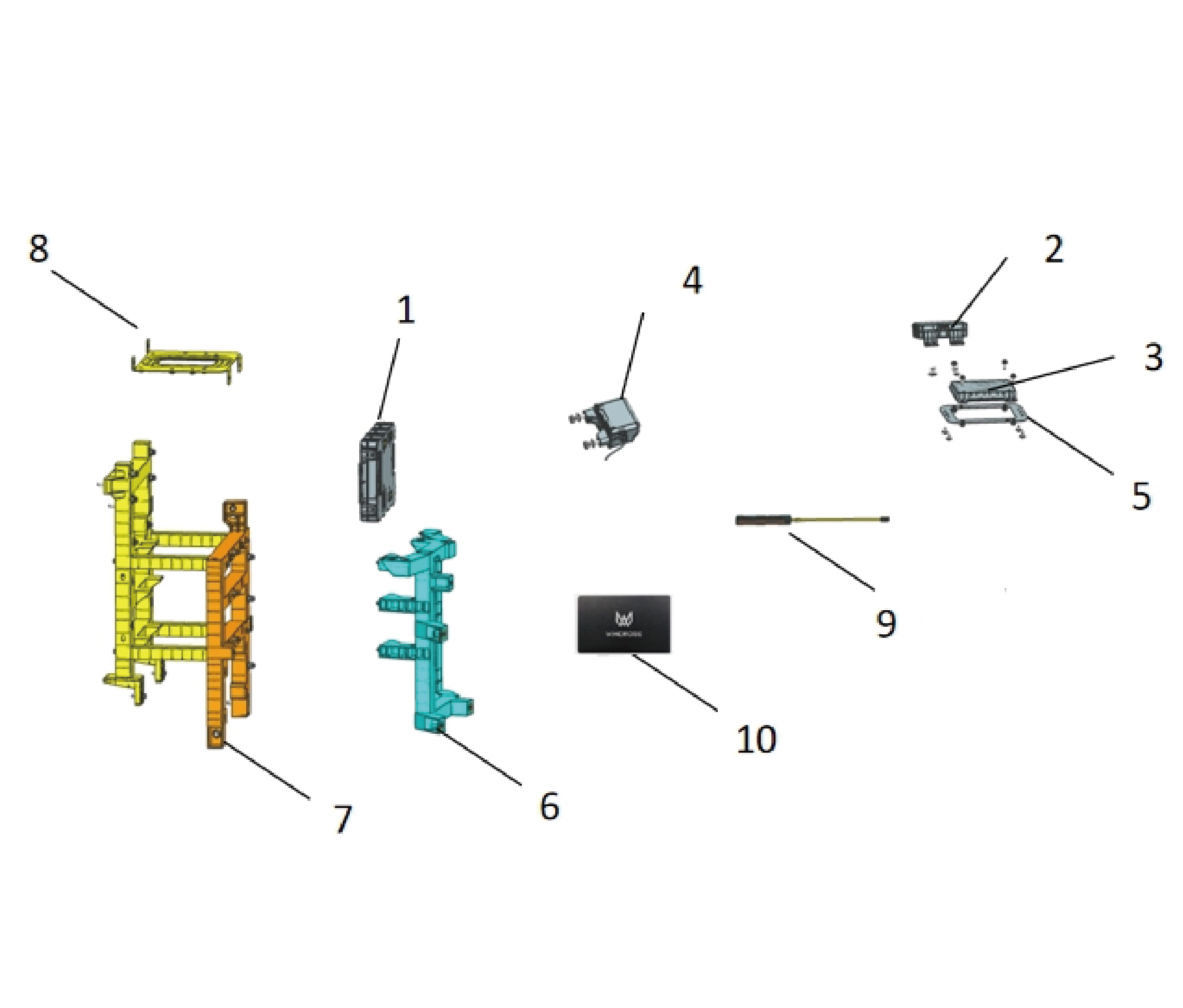
1.
6.
Lower Left Mounting Brackt
Body Controller
7.
2.
NFC Antenna
Lower Left Instrument Panel Controller Mounting
Bracket
3.
8.
Wireless Charging Mode
EBS Bracket
4.
Pillar Lock
9.
Bluetooth + NFC Antenna
5.
10.
Wireless Charging Module Braket
Card Key
7.8.4 System Schematic Diagram
7.8.4.1 Electrical Schematic Diagram
7.8.5 Diagnostic Information and Steps
7.8.5.1 Diagnostic Description
Before diagnosing faults in the vehicle body controller device, refer toDescription And OperationUnderstanding and familiarizing
oneself with the working principle of the vehicle body controller device before starting system diagnosis can help determine the
correct fault diagnosis steps when a fault occurs, and more importantly, it can help determine the situation described by the
customer belongs to normal operation. Any fault diagnosis of the vehicle body controller device should start with routine
inspection, guiding maintenance personnel to take the next logical step for fault diagnosis. Understanding and correctly using the
diagnostic process can shorten the diagnosis time and avoid misjudgment of faulty parts.
7.8.5.2 Routine Inspection
• Check for aftermarket devices that may affect the operation of the vehicle body control system, ensuring that these devices do
not affect the operation of the vehicle body control system.
• Check system components that are easily accessible or visible to ensure that there is no obvious damage or potential
malfunction.
7.8.5.3 DTC Confirmation
1. Connect the diagnostic tool to the diagnostic interface, read and record the DTC, and then clear the DTC.
2. Run the vehicle again.
3. Read the fault code of the control system again to confirm if there are any fault codes output from the system.
– Yes:Diagnose based on the output fault code.
– No:Perform intermittent fault checks, refer to Inspection Of Intermittent Faults
7.8.5.4 List Of Diagnostic Trouble Codes (DTC)
BDCU
Fault Description
Exclusion Method
Fault Code
High battery voltage
B111717
Refer to BDCU Power Fault
Low Battery Voltage
B111716
On the BCANFD4 network, the BDCU
cannot receive the CAN packet ADCU_
U015787
LCMD whose ID is 0x18FE4131, and
the communication between the BDCU
and the ADCU node fails. Procedure
The BDCU on BCANFD3 limps home
(send ID: 0x18FFF021 (BDCU_NM_
U220200
Limphome). Receive ID:0x18FFF058,
Refer to BDCU Communication Fault
(SSM_NM_Limphome)). The send or
receive timeout occurred. Procedure
There is no CAN message ABL_Light
with the ID of 0x18FF1455 received by
U018087
BDCU on the BCANFD1 network, and
the communication with the ADBL node
is lost
The Ethernet MDIO chip is abnormal
U018087
Fault Description
Exclusion Method
Fault Code
The BDCU on the BCANFD2 network
fails to receive the CAN message
U01A187
SJBUN_Status with the ID of
0x18FF1659, losing communication
with the SJBUN node
The BDCU on the BCANFD1 network
fails to receive the CAN message
U01A087
SJBUP_Status with the ID of
0x18FF1554, losing communication
with the SJBUP node
The BDCU on the BCANFD1 network is
unable to receive the CAN message
TPMS_F_TirePressure with the ID of
U012787
0x18FEF433, losing communication
with the TPMS_F node
The BDCU on the BCANFD2 network
fails to receive the CAN message AC_
U016487
RearStatus with the ID of 0x18FF2419,
losing communication with the AC node
The BDCU on the BCANFD2 network
fails to receive the CAN message
U018187
ADBR_Light with the ID of
0x18FF145A, losing communication
with the ADBR node
The BDCU on the BCAND2 network
cannot receive the CAN message AVA_
U014187
Status with ID 0x18FF0E57 and has lost
communication with the AVAS node
The BDCU on the BCANFD2 network
fails to receive the CAN message SDM_
U02A687
Status with the ID of 0x18FF0F1D,
losing communication with the SDM
node
The BDCU on the BCANFD3 network
fails to receive the CAN message DCM_
U019987
DC2 with the ID of 0x18FDA54F, losing
communication with the DCM node
The BDCU on the CANFD3 network
fails to receive the CAN message EPM_
U018887
Motor with the ID of 0x18F00E52, losing
communication with the EPM node
Fault Description
Exclusion Method
Fault Code
The BDCU on the BCANFD3 network is
unable to receive the CAN message
U014487
PWC_CS with the ID of 0x18FF0953
and loses communication with the PWC
node
The BDCU on the BCANFD3 network
fails to receive the CAN message SSM_
U024A87
Status with the ID of 0x18FF0F58 and
loses communication with the SSM
node
The BDCU on the BCANFD4 network
fails to receive the CAN message
TPMS_Trailer_TirePressure with the ID
U012F87
of 0x18FEF45D and loses
communication with the TPMS_Trailer
node
The BDCU on the BCAN5 network fails
to receive the CAN message ESCL_
U021287
STATUS with the ID of 0x18FE054D and
loses communication with the ESCL
node
The BDCU on the CANFD3 network
fails to receive the CAN message
U019887
TGW_TD_Time with the ID of
0x18FEE6EE and loses communication
with the TGW node
U007C88
BCANFD1 network Busoff
U007D88
BCANFD2 network Busoff
U007E88
BCANFD3 network Busoff
U007F88
BCANFD4 network Busoff
U008388
BCANFD5 network Busoff
U008488
BCAN6 network Busoff
The BDCU on the BCAN6 network fails
to receive the CAN message
U10538A
BCANFD6_RXID_NBSM_0x200 with
the ID of 0x200 and loses
communication with the Bluetooth node
Fault Description
Exclusion Method
Fault Code
The BDCU on CANFD3 fails to receive
the message with the ID of
0x18FEC1EE (CDCU_VDHR), resulting
U015687
in a timeout error and leading to the
belief that it has lost contact with the
CDCU
The BDCU on CANFD3 fails to receive
the message with the ID of
0x18FCC231 (VDC_HSS1), which
U012287
leads to a timeout error and makes it
consider that it has lost contact with the
VDCU
The BDCU on CANFD3 fails to receive
the message with the ID of
U012187
0x08FE6E0B (EBS_HRW) and thus
generates a timeout error, believing that
it has lost contact with the EBS
The BDCU on CANFD3 fails to receive
the message with the ID of 0x18FE1250
U012887
(EPBS1_EPB), which results in a
timeout error and leads to the belief that
it has lost contact with the EPB
U007588
CANFD3 BusOff
On BCANFD1, the BDCU enters limp -
home mode (sends ID:0x18FFF021
(BDCU_NM_Limphome), and receives
IDs:0x18FFF054 (SJBUP_NM_
U220600
Limphome), 0x18FFF055 (ADBL_NM_
Limphome), 0x18FFF059 (SJBUN_NM_
Limphome)), and a send or receive
timeout occurs
On BCANFD2, the BDCU enters limp -
home mode (sending ID:0x18FFF021
(BDCU_NM_Limphome) and receiving
U220700
IDs: 0x18FFF05A (ADBR_NM_
Limphome), 0x18FFF059 (SJBUN_NM_
Limphome)), resulting in a send or
receive timeout
Fault Description
Exclusion Method
Fault Code
On BCANFD3, the BDCU enters limp-
home mode (sending ID:0x18FFF021
(BDCU_NM_Limphome) and receiving
U220A00
ID:0x18FFF058 (SSM_NM_
Limphome)), which results in a send or
receive timeout
U015788
Communication with CAMF is lost
U238084
SQI insufficient
Refer to BDCU Internal Fault
The Ethernet MDIO chip is abnormal
U238208
Unexpected Ethernet connection loss
U238108
Refer to BDCU Ethernet Fault
The BDCU on the LIN1 network fails to
receive the slave - response message
U120387
RSL1 with the ID of 0x12, and the
communication with the RSL node is
abnormal
The BDCU on the LIN1 network can't
receive the slave - response message
Refer to BDCU LIN1 Communication
U105388
RSL2 with the ID of 0x13, and there is
Fault
an abnormal communication with the
RSL node
On the LIN1 network, the BDCU is
unable to receive the slave - response
U105389
message RSL3 with an ID of 0x14, and
the communication with the RSL node is
abnormal
Main vehicle right front turn signal Fault
Refer to Right Front Turn Signal Fault
B151635
Main vehicle left front turn signal Fault
Refer to Left Front Turn Signal Fault
B151735
The high beam/overtaking switch is
Refer to High Beam Overtaking Switch
B152532
faulty
Fault
The wiper combination switch is faulty
Refer to Wiper Switch Fault
B152632
The high voltage pressure signal input is
B152933
faulty
Refer to High Pressure & Temperature
Sensor Fault
The high voltage pressure signal input is
B152A33
faulty
The ON power feedback of the electrical
Refer to KL15 Power Feedback Signal
B153036
box is faulty
Fault
The power-on command output is faulty
B15353F
Refer to KL15 Power On/off Command
Output Signal Fault
The power-off command output is faulty
B15363F
The power supply to the height
Refer to Headlight Adjustment Motor
adjustment module of the low light is
B153831
Fault
faulty
Fault Description
Exclusion Method
Fault Code
The power supply to the left center left
Refer to Left Center Rear Turn Signal
rear turn signal of the main vehicle is
B153C31
Fault
faulty
The power supply of the right, middle
Refer to Right Center Rear Turn Signal
and right rear turn signal of the main
B153D31
Fault
vehicle is faulty
Refer to Wiper Motor Low-speed Signal
The wiper is faulty at low speed
B15403F
Fault
Refer to High Speed Signal Fault Of
High-speed wiper failure
B15413F
Wiper Motor
The wiper washing motor is faulty
Refer to Washing Motor Fault
B15423F
Rearview Mirror Heating Failure
Refer to Rearview Mirror Heating Fault
B154437
The charging port is unlocked.
B15453F
Refer to Charging Port Cover Lock
Procedure
Motor Fault
The charging port is blocked
B15463F
External toolbox motor unlocking failure
B15493F
Refer to External Toolbox Motor Fault
B154A3F
External toolbox motor lockout failure
The skylight visor opening function
B154B3F
failed
Refer to Fault Of The Sunroof Sunshade
The awning curtain closing function is
B154C3F
faulty
The upward adjustment of the left
B154D37
rearview mirror fails
The downward adjustment of the left
B154E37
rearview mirror fails
Refer to Left Physical Rearview Mirror
Adjustment Signal Fault
The left rearview mirror fails to adjust to
B154F37
the left
The left rearview mirror fails to adjust to
B155037
the right
The right rearview mirror fails to adjust
B155137
upwards
Right rearview mirror downward
B155237
adjustment failure
Refer to Right Physical Rearview Mirror
Adjustment Signal Fault
The left adjustment of the right rearview
B155337
mirror fails
The right rearview mirror fails to adjust
B155437
to the right
Refer to Interwheel Lock Solenoid Valve
The interwheel solenoid valve is faulty
B15573F
Fault
Refer to Main driver reading light power
Main driver reading light power supply
B155D31
supply failure
failure
Fault Description
Exclusion Method
Fault Code
Sleeper reading lamp power supply
Refer to Sleeper Reading Light Fault
B155E31
failure
The ceiling light power supply is faulty
Refer to Sky Roof Light Fault
B155F31
The power supply of the indicator lamp
Refer to Position Lamp Fault
B156031
is faulty
The backlight lighting power supply is
Refer to Backlight Power Fault
B156331
faulty
Danger alarm indicator key light power
Refer to Hazard Alarm Switch Backlight
B156431
supply failure
Power Fault
Secondary car window rising power
B156B31
supply failure
Refer to Right window regulator Fault
Secondary car window down power
B156C31
supply failure
Main driving window rising power supply
B156931
failure
Refer to Left window regulator Fault
Main driving window down power supply
B156A31
failure
7.8.5.5 BDCU Power Fault
1. DTC Monitoring Logic
Description
DTC Trigger Conditions
Faulty Part
DTC Code
When the supply voltage rises to the upper limit of the
diagnostic voltage, the ECU immediately stops the
High battery voltage
network-related diagnostic function. When the supply
B111717
1. Main battery
voltage is in the overvoltage state for 2 seconds, the
2. Low voltage
overvoltage DTC is recorded
charging system
When the supply voltage drops below the diagnostic
3. Wiring harness
voltage limit, the ECU immediately stops the network-
4.BDCU
Low Battery Voltage
related diagnostic function. When the supply voltage is
B111716
in the undervoltage state for 2 seconds, the
undervoltage DTC is recorded
2.Circuit Diagram
Smart Junction
Left combination switch
Box - Chassis
Battery
Wash
Inter-
High
Low
Left
Right
Passing
High
mittent
speed
speed
OFF
turn
turn
AUTO
light
beam
B12-1
3KΩ
2180Ω
Total body power
3KΩ
2.2KΩ 1.5KΩ
680Ω
supply B+ L22
680Ω
150Ω
IP17-7 IP17-6
IP17-9
IP17-5
IP17-10
High beam/passing
Wiper switch signal
light switch B435
Wash switch B401
simulatively B416
Left/right turn
switch B415
B434
B01-1
B07-6
B07-5
Smart Junction
22
23
20
19
I3_IP_B
I3_IP_B
I3_IP_B
I3_IP_B
21
I3_IP_B
Box - Body
22
23
20
19
I3_B_IP
I3_B_IP
I3_B_IP
I3_B_IP
21
I3_B_IP
BDCU-B+1 P105
BDCU-B+2 P106
Wiper switch signal
High beam/passing
light switch B435
Wash switch B401
Left/right turn
simulatively B416
switch B415
B434
B65-3
B65-9
B48-16
B48-34
B48-1
B48-15
B48-35
BDCU
120Ω
B65-7 B65-16
B48-19
B48-39
B48-16
B46-20
B47-2
BCANFD3-L BL03
BCANFD3-H BH03
Ground Z05
Analog switch (light/wip-
Ground Z05
Low light height gear
er) public area B416
Low-beam adjustment
signal output B302
motor + B220
Ground Z05
G27
Power source B220b
Power source B220a
Gear signal B302b
Gear signal B302a
Ground B416
Ground B416
B37-1
B37-2
B37-3
B15-1
B15-3
B15-2
BCANFD3
Right low-beam adjustment motor
Left low-beam adjustment motor
Ground Z01
Smart Junction
Ground B436e
Ground B436f
Battery
BU02-1
Box - Chassis
Ground B436e
Ground B436d
G22
Front mask
Outlet water
C80-1
switch
Inlet water
temperature
C81-1
C1-1
temperature
sensor
Compressor
C70-2
sensor
Ambient
exhaust
B38-1
BU02-1
KL15 Power supply 1 G01
temp
temperature
C80-2
sensor
sensor
C81-2
1
I7_C_B
Front cover unlocked
C70-1
B38-2
signal B616a
Inlet temperature
Effluent tempera-
ture signal B410
sensorily B436e
I7_B_C
1
signal B431
Sensor signal
KL15-1 G01a
B430
Outdoor temperature signal B411
2
I_BU_B
6
7
9
I3_C_B
I3_C_B
I3_C_B
8
I3_C_B
2
I_B_BU
6
7
9
I3_B_C
I3_B_C
I3_B_C
8
I3_B_C
Front cover unlocked
KL15 power signal
KL15-1 G01a
feedback G01n
Inlet temperature
Effluent tempera-
ture signal B410
Sensor signal
signal B616a
signal B431
sensorily B436
B430
B48-11
B48-10
B48-30
B48-31
B48-36
B64-16
B47-4
BDCU
120Ω
B64-6
B61-26
B48-20
B61-12
B48-40
B48-37
B48-17
Turn to oil tank level
sensor signal B606
GWCANFD3-H TH03
GWCANFD3-L TL03
BCAN6-H BH06
BCANFD1-H BH01
BCAN6-L BL06
BCANFD1-L BL01
Ground Z56
G06
I4_B_C
18
Turn to tank
I4_C_B
18
C49-2
level sensor
Turn to oil tank level
sensor signal B606
C49-1
BCANFD1
GWCANFD3
BCANFD6
3. Diagnostic Steps
Step 1:DTC confirmation. Refer to DTC Confirmation
Step 2:Routine inspection. Refer to Routine Inspection
Step 3:Check if there are any other module power fault codes besides BDCU?
Check the main battery. Refer to Inspection Of The Main Battery
– Yes:
Check the low-voltage charging system. Refer to DCDC1 Low-voltage Charging System Malfunction
Next step
– No:
Step 4:Check the BDCU power supply and grounding harness.
Step 5:BDCU rewrite configuration code, software reload, upgrade.
Step 6:Replace the BDCU. Refer to Replacement Of Body Domain Control Uint
Step 7:Clear and confirm DTC.
7.8.5.6 BDCU Communication Fault
1. DTC Monitoring Logic
Description
DTC Trigger Conditions
Faulty Part
DTC Code
On the BCANFD4
network, the BDCU
cannot receive the
1.The timeout period for receiving CAN ADCU_LCMD
CAN packet ADCU_
reaches 10 *Cycle (Cycle = 100 ms).
LCMD whose ID is
U015787
2.KL30 on;
0x18FE4131, and the
3. Diagnostic voltage range;
communication
between the BDCU
and the ADCU node
fails. Procedure
The BDCU on
BCANFD3 limps home
(send ID:0x18FFF021
(BDCU_NM_
1. Wiring harness
Limphome). Receive
The BDCU on the BCANFD3 limps home, resulting in a
2.BDCU
U220200
ID:0x18FFF058,
send or receive timeout.
(SSM_NM_
Limphome)). The send
or receive timeout
occurred. Procedure
There is no CAN
message ABL_Light
with the ID of
1. The timeout period for receiving CAN packets ABL_
0x18FF1455 received
LightJIE reaches 10 *Cycle (Cycle = 100 ms).
U018087
by BDCU on the
2.KL15 on;
BCANFD1 network,
3. Diagnostic voltage range;
and the
communication with
the ADBL node is lost
Description
DTC Trigger Conditions
Faulty Part
DTC Code
1.In section 1 and 4_1, add DID:2506 Debug log path
information, 2507 Bluetooth primary node VIN code,
2508 Bluetooth primary node serial number, 2509
The Ethernet MDIO
U018087
Bluetooth primary node software version, 250A
chip is abnormal
Bluetooth left node software version, 250B Bluetooth
right node software version, and 250C Bluetooth front
node software version
The BDCU on the
BCANFD2 network
1. The timeout period for receiving CAN message
fails to receive the
SJBUN_Status reaches 10 *Cycle (Cycle = 100 ms).
CAN message
U01A187
2.network wake up;
SJBUN_Status with
3.Diagnostic voltage range;
the ID of 0x18FF1659,
losing communication
with the SJBUN node
The BDCU on the
BCANFD1 network
1. The timeout period for receiving CAN message
fails to receive the
SJBUP_Status reaches 10 *Cycle (Cycle = 100 ms).
CAN message
U01A087
2.network wake up;
SJBUP_Status with
3. Diagnostic voltage range;
the ID of 0x18FF1554,
losing communication
with the SJBUP node
The BDCU on the
BCANFD1 network is
1. The TPMS_F_TirePressure receiving timeout period
unable to receive the
reaches 10 *Cycle (Cycle = 500 ms).
CAN message TPMS_
U012787
2.KL15 on;
F_TirePressure with
3. Diagnostic voltage range;
the ID of 0x18FEF433,
losing communication
with the TPMS_F node
The BDCU on the
BCANFD2 network
1.The receiving timeout of the CAN message AC_
fails to receive the
RearStatus reaches 10 * Cycle (where Cycle = 100 ms).
CAN message AC_
U016487
2.KL15 on;
RearStatus with the ID
3. Diagnostic voltage range;
of 0x18FF2419, losing
communication with
the AC node
Description
DTC Trigger Conditions
Faulty Part
DTC Code
The BDCU on the
BCANFD2 network
1.The receiving timeout of the CAN message ADBR_
fails to receive the
Light reaches 10 * Cycle (where Cycle = 100 ms).
CAN message ADBR_
U018187
2.KL15 on;
Light with the ID of
3. Diagnostic voltage range;
0x18FF145A, losing
communication with
the ADBR node
The BDCU on the
BCANFD2 network
1. The timeout period for receiving CAN packet AVAS_
fails to receive the
Status reaches 10 *Cycle (Cycle = 500 ms).
CAN message AVAS_
U014187
2.KL15 on;
Status with the ID of
3. Diagnostic voltage range;
0x18FF0E57, losing
communication with
the AVAS node
The BDCU on the
BCANFD2 network
1. The timeout period for receiving CAN SJBUN_Status
fails to receive the
packets reaches 5000 ms(Cycle = 1000 ms).
CAN message SDM_
U02A687
2.network wake up;
Status with the ID of
3. Diagnostic voltage range;
0x18FF0F1D, losing
communication with
the SDM node
The BDCU on the
BCANFD3 network
1. The timeout period for receiving CAN DCM_DC2
fails to receive the
packets reaches 10 *Cycle (Cycle = 100 ms).
CAN message DCM_
U019987
2. Power on the DCM.
DC2 with the ID of
3. Diagnostic voltage range;
0x18FDA54F, losing
communication with
the DCM node
The BDCU on the
CANFD3 network fails
1. The timeout period for receiving CAN packet EPM_
to receive the CAN
Motor reaches 10 *Cycle (Cycle = 200 ms).
message EPM_Motor
U018887
2.KL15 on;
with the ID of
3. Diagnostic voltage range;
0x18F00E52, losing
communication with
the EPM node
Description
DTC Trigger Conditions
Faulty Part
DTC Code
The BDCU on the
BCANFD3 network is
1. The timeout period for receiving CAN packets PWC_
unable to receive the
CS reaches 5000(Cycle = 1000 ms).
CAN message PWC_
U014487
2.KL15 on;
CS with the ID of
3. Diagnostic voltage range;
0x18FF0953 and loses
communication with
the PWC node
The BDCU on the
BCANFD3 network
1. The timeout period for receiving CAN packet SSM_
fails to receive the
Status reaches 10 *Cycle (Cycle = 200 ms).
CAN message SSM_
U024A87
2.KL15 on;
Status with the ID of
3. Diagnostic voltage range;
0x18FF0F58 and loses
communication with
the SSM node
The BDCU on the
BCANFD4 network
fails to receive the
1. The TPMS_Trailer_TirePressure receive timeout
CAN message TPMS_
period reaches 5000 (Cycle = 50000 ms).
Trailer_TirePressure
U012F87
2.KL15 on;
with the ID of
3. Diagnostic voltage range;
0x18FEF45D and
loses communication
with the TPMS_Trailer
node
The BDCU on the
BCAN5 network fails
1.The receiving timeout of the CAN message ESCL_
to receive the CAN
STATUS reaches 10 * Cycle (where Cycle = 50 ms).
message ESCL_
U021287
2.KL15 on;
STATUS with the ID of
3. Diagnostic voltage range;
0x18FE054D and
loses communication
with the ESCL node
The BDCU on the
CANFD3 network fails
1. The timeout period for receiving CAN TGW_TD_
to receive the CAN
Time packets reaches 5000(Cycle = 1000 ms).
message TGW_TD_
U019887
2.KL15 on;
Time with the ID of
3. Diagnostic voltage range;
0x18FEE6EE and
loses communication
with the TGW node
Description
DTC Trigger Conditions
Faulty Part
DTC Code
1. The BCANFD1 network CAN controller enters the
BusOff state.
BCANFD1 network
U007C88
2.network wake up;
Busoff
3. Diagnostic voltage range;
1. The BCANFD2 network CAN controller enters the
BusOff state.
BCANFD2 network
U007D88
2.network wake up;
Busoff
3. Diagnostic voltage range;
1. The BCANFD3 network CAN controller enters BusOff
state;
BCANFD3 network
U007E88
2.network wake up;
Busoff
3. Diagnostic voltage range;
1. The BCANFD4 network CAN controller enters BusOff
state;
BCANFD4 network
U007F88
2.network wake up;
Busoff
3. Diagnostic voltage range;
1. The BCANFD5 network CAN controller enters BusOff
state;
BCANFD5 network
U008388
2.network wake up;
Busoff
3. Diagnostic voltage range;
1. The BCAN6 network CAN controller enters the
BusOff state;
BCAN6 network
U008488
2.network wake up;
Busoff
3. Diagnostic voltage range;
The BDCU on the
BCAN6 network fails
1. The timeout period for receiving CAN packets
to receive the CAN
BCANFD6_RXID_NBSM_0x200 reaches 10 x Cycle
message BCANFD6_
(Cycle = 100 ms).
U10538A
RXID_NBSM_0x200
2.KL15 on;
with the ID of 0x200
3. Diagnostic voltage range;
and loses
communication with
the Bluetooth node
Description
DTC Trigger Conditions
Faulty Part
DTC Code
The BDCU on
CANFD3 fails to
receive the message
1. The timeout period for receiving CAN CDCU_VDHR
with the ID of
packets reaches 10000(Cycle = 1000ms).
0x18FEC1EE (CDCU_
U015687
2.KL15 on;
VDHR), resulting in a
3. Diagnostic voltage range;
timeout error and
leading to the belief
that it has lost contact
with the CDCU
The BDCU on
CANFD3 fails to
receive the message
1. The timeout period for receiving CAN packets VDC_
with the ID of
HSS1 reaches 1000(Cycle = 100ms).
0x18FCC231 (VDC_
U012287
2.KL15 on;
HSS1), which leads to
3. Diagnostic voltage range;
a timeout error and
makes it consider that
it has lost contact with
the VDCU
The BDCU on
CANFD3 fails to
receive the message
1. The timeout period for receiving CAN EBS_HRW
with the ID of
packets reaches 20(Cycle = 200ms).
0x08FE6E0B (EBS_
U012187
2.KL15 on;
HRW) and thus
3. Diagnostic voltage range;
generates a timeout
error, believing that it
has lost contact with
the EBS
The BDCU on
CANFD3 fails to
receive the message
1. The timeout period for receiving CAN packets VDC_
with the ID of
HSS1 reaches 1000(Cycle = 100ms).
0x18FE1250 (EPBS1_
U012887
2.KL15 on;
EPB), which results in
3. Diagnostic voltage range;
a timeout error and
leads to the belief that
it has lost contact with
the EPB
U007588
CANFD3 BusOff
CANFD3 BusOff occurs for five consecutive times
Description
DTC Trigger Conditions
Faulty Part
DTC Code
On BCANFD1, the
BDCU enters limp -
home mode (sends
ID:0x18FFF021
(BDCU_NM_
Limphome), and
receives
The BDCU on BCANFD1 limps home, resulting in
IDs:0x18FFF054
U220600
sending or receiving timeout.
(SJBUP_NM_
Limphome),
0x18FFF055 (ADBL_
NM_Limphome),
0x18FFF059 (SJBUN_
NM_Limphome)), and
a send or receive
timeout occurs
On BCANFD2, the
BDCU enters limp -
home mode (sending
ID:0x18FFF021
(BDCU_NM_
Limphome) and
The BDCU on BCANFD2 limps home, resulting in
receiving
U220700
sending or receiving timeout.
IDs:0x18FFF05A
(ADBR_NM_
Limphome),
0x18FFF059 (SJBUN_
NM_Limphome)),
resulting in a send or
receive timeout
On BCANFD3, the
BDCU enters limp-
home mode (sending
ID:0x18FFF021
(BDCU_NM_
Limphome) and
The BDCU on the BCANFD3 limps home, resulting in a
U220A00
receiving
send or receive timeout.
ID:0x18FFF058
(SSM_NM_
Limphome)), which
results in a send or
receive timeout
Description
DTC Trigger Conditions
Faulty Part
DTC Code
1. The timeout period for receiving CAN CAMF_Stauts
reaches 10 x Cycle (Cycle =100 ms).
Communication with
U015788
2.KL15 on;
CAMF is lost
3. Diagnostic voltage range;
2.Circuit Diagram
Smart Junction
Left combination switch
Box - Chassis
Battery
Wash
Inter-
High
Low
Left
Right
Passing
High
mittent
speed
speed
OFF
turn
turn
AUTO
light
beam
B12-1
3KΩ
2180Ω
Total body power
3KΩ
2.2KΩ 1.5KΩ
680Ω
supply B+ L22
680Ω
150Ω
IP17-7 IP17-6
IP17-9
IP17-5
IP17-10
High beam/passing
Wiper switch signal
light switch B435
Wash switch B401
simulatively B416
Left/right turn
switch B415
B434
B01-1
B07-6
B07-5
Smart Junction
22
23
20
19
I3_IP_B
I3_IP_B
I3_IP_B
I3_IP_B
21
I3_IP_B
Box - Body
22
23
20
19
I3_B_IP
I3_B_IP
I3_B_IP
I3_B_IP
21
I3_B_IP
BDCU-B+1 P105
BDCU-B+2 P106
Wiper switch signal
High beam/passing
light switch B435
Wash switch B401
Left/right turn
simulatively B416
switch B415
B434
B65-3
B65-9
B48-16
B48-34
B48-1
B48-15
B48-35
BDCU
120Ω
B65-7 B65-16
B48-19
B48-39
B48-16
B46-20
B47-2
BCANFD3-L BL03
BCANFD3-H BH03
Ground Z05
Analog switch (light/wip-
Ground Z05
Low light height gear
er) public area B416
Low-beam adjustment
signal output B302
motor + B220
Ground Z05
G27
Power source B220b
Power source B220a
Gear signal B302b
Gear signal B302a
Ground B416
Ground B416
B37-1
B37-2
B37-3
B15-1
B15-3
B15-2
BCANFD3
Right low-beam adjustment motor
Left low-beam adjustment motor
Ground Z01
Smart Junction
Ground B436e
Ground B436f
Battery
BU02-1
Box - Chassis
Ground B436e
Ground B436d
G22
Front mask
Outlet water
C80-1
switch
Inlet water
temperature
C81-1
C1-1
temperature
sensor
Compressor
C70-2
sensor
Ambient
exhaust
B38-1
BU02-1
KL15 Power supply 1 G01
temp
temperature
C80-2
sensor
sensor
C81-2
1
I7_C_B
Front cover unlocked
C70-1
B38-2
signal B616a
Inlet temperature
Effluent tempera-
ture signal B410
sensorily B436e
I7_B_C
1
signal B431
Sensor signal
KL15-1 G01a
B430
Outdoor temperature signal B411
2
I_BU_B
6
7
9
I3_C_B
I3_C_B
I3_C_B
8
I3_C_B
2
I_B_BU
6
7
9
I3_B_C
I3_B_C
I3_B_C
8
I3_B_C
Front cover unlocked
KL15 power signal
KL15-1 G01a
feedback G01n
Inlet temperature
Effluent tempera-
ture signal B410
Sensor signal
signal B616a
signal B431
sensorily B436
B430
B48-11
B48-10
B48-30
B48-31
B48-36
B64-16
B47-4
BDCU
120Ω
B64-6
B61-26
B48-20
B61-12
B48-40
B48-37
B48-17
Turn to oil tank level
sensor signal B606
GWCANFD3-H TH03
GWCANFD3-L TL03
BCAN6-H BH06
BCANFD1-H BH01
BCAN6-L BL06
BCANFD1-L BL01
Ground Z56
G06
I4_B_C
18
Turn to tank
I4_C_B
18
C49-2
level sensor
Turn to oil tank level
sensor signal B606
C49-1
BCANFD1
GWCANFD3
BCANFD6
Left center control switch devices
IP10-4
IP10-1
IP10-2
IP10-5
IP10-6
IP10-9
IP10-8
IP10-3
Left window lift switch
Main drive visor lift
Right window drop
Left window drop
lowering switch B404
Backlight + B218
Main drive shade
Right window lift
switch B506
switch B520
switch B507
switch B521
Ground Z12
B522
18
19
20
21
22
23
8
I2_IP_B
I2_IP_B
I2_IP_B
I2_IP_B
I2_IP_B
I2_IP_B
I3_IP_B
18
19
20
21
22
23
8
I2_B_IP
I2_B_IP
I2_B_IP
I2_B_IP
I2_B_IP
I2_B_IP
I3_B_IP
G14
Left window lift switch
Main drive visor lift
Right window drop
lowering switch B404
Main drive shade
Left window drop
Right window lift
Backlight + B218
switch B506
switch B520
switch B521
switch B507
B522
B61-6
B61-20
B61-21
B61-22
B48-4
B61-7
B46-18
BDCU
120Ω
120Ω
B46-18
B61-27
B48-18
B48-38
B61-13
Backlight + B218
Backlight +
B218
ESCL-BCAN5-H BH05
ESCL-BCAN5-L BL05
BCANFD2-H BH02
BCANFD2-L BL02
8
I3_B_IP
8
I3_IP_B
Backlight power supply PWM+ B218b
Backlight +
B218
Backlight PWM B218c
Block the backlight
Backlight + B218e
PWM B218d
backlight B218a
B85-7
IP10-3
IP16-4
IP21-3
IP09-4
BCANFD2
ESCL-BCAN5
Sleeper
Right center
Sliding door
Left center
switch
Clock-spring
control switch
switch
control switch
devices
Ground Z11
Ground Z12
T-GW Ethernet
Ground Z12b
Ground Z12a
B78-6
B78-5
G28
Ground Z11
Ground Z11
Sliding door
G14
IP09-3
IP09-1
switch
Step
Step
B28-1
B29-1
light 1
light 2
BDCU-TGW 100 Mbit Ethernet TBN
BDCU-TGW 100 Mbit Ethernet TBP
IP09-2
IP09-4
Sliding door
switch B424
B28-2
B29-2
Backlight +
B218e
Step light +
Step light
+ B315a
B315b
Backlight + B218
8
28
I3_IP_B
I1_IP_B
Sliding door
switch B424
Step light +
8
28
I3_B_IP
I1_B_IP
B315
B47-15
B61-17
B64-17
B61-16
B46-18
BDCU
120Ω
B46-12
B46-23
B48-40
B48-20
B48-22
B46-11
B48-2
Left center rear
Right front turn signal fault feedback
turn signal B223
Left front turn signal fault feedback
GWCANFD3-H TH03
GWCANFD3-L TL03
Right front turn signal B211
Left front turn signal B212
B402
B422
21
I9_B_C
21
I9_C_B
Left steering
B223
Front left
Front right
B16-4
B33-4
B16-6
B33-6
combina-
combina-
tion light
tion light
C17-2
B33-5
Ground Z01 B16-5
GWCANFD3
Combination
C17-1
lamp-lh rr
Ground Z07
Ground Z68
G22
G23
G01
3. Diagnostic Steps
Step 1:DTC confirmation. Refer to DTC Confirmation
Step 2:Routine inspection. Refer to Routine Inspection
Step 3:Check the BCAN6 bus communication harness. Refer to Inspection Of BCAN6 Bus Network Integrity
Step 4:Check the BCANFD3 bus communication harness. Refer to Inspection Of BCAND3 Bus Network Integrity
Step 5:Check the BCAN5 bus communication harness. Refer to Inspection Of BCAN5 Bus Network Integrity
Step 6:Check the BCAND2 bus communication harness. Refer to Inspection Of BCAND2 Bus Network Integrity
Step 7:Check the CANFD3 bus communication harness. Refer to Inspection Of CANFD3 Bus Network Integrity
Step 8:Check the BCANFD1 bus communication harness. Refer to Inspection Of BCAND1 Bus Network Integrity
Step 9:BDCU rewrite configuration code, software reload, upgrade.
Step 10:Replace the BDCU. Refer to Replacement Of Body Domain Control Uint
Step 11:Clear and confirm DTC.
7.8.5.7 BDCU Internal Fault
1. DTC Monitoring Logic
Description
DTC Trigger Conditions
Faulty Part
DTC Code
U238084
SQI insufficient
SQI below the threshold occurs 20 times within 60s
The Ethernet MDIO
1.BDCU
Unable to read SWITCH chip register
U238208
chip is abnormal
2. Diagnostic Steps
Step 1:DTC confirmation. Refer to DTC Confirmation
Step 2:Routine inspection. Refer to Routine Inspection
Step 3:BDCU rewrite configuration code, software reload, upgrade.
Step 4:Replace the BDCU. Refer to Replacement Of Body Domain Control Uint
Step 5:Clear and confirm DTC.
7.8.5.8 BDCU Ethernet Fault
1. DTC Monitoring Logic
Description
DTC Trigger Conditions
Faulty Part
DTC Code
If the current link status of the Ethernet port is not link-
Up, the counter increases by 1. If the current link status
1. Wiring harness
Unexpected Ethernet
U238108
is not link-Up for 10 consecutive times, a fault is
2.BDCU
connection loss
reported
2.Circuit Diagram
Ground Z11
Ground Z12
T-GW Ethernet
Ground Z12b
Ground Z12a
B78-6
B78-5
G28
Ground Z11
Ground Z11
Sliding door
G14
IP09-3
IP09-1
switch
Step
Step
B28-1
B29-1
light 1
light 2
BDCU-TGW 100 Mbit Ethernet TBN
BDCU-TGW 100 Mbit Ethernet TBP
IP09-2
IP09-4
Sliding door
switch B424
B28-2
B29-2
Backlight +
B218e
Step light +
Step light
+ B315a
B315b
Backlight + B218
8
28
I3_IP_B
I1_IP_B
Sliding door
switch B424
Step light +
8
28
I3_B_IP
I1_B_IP
B315
B47-15
B61-17
B64-17
B61-16
B46-18
BDCU
120Ω
B46-12
B46-23
B48-40
B48-20
B48-22
B46-11
B48-2
Left center rear
Right front turn signal fault feedback
turn signal B223
Left front turn signal fault feedback
GWCANFD3-H TH03
GWCANFD3-L TL03
Right front turn signal B211
Left front turn signal B212
B402
B422
21
I9_B_C
21
I9_C_B
Left steering
B223
Front left
Front right
B16-4
B33-4
B16-6
B33-6
combina-
combina-
tion light
tion light
C17-2
B33-5
Ground Z01 B16-5
GWCANFD3
Combination
C17-1
lamp-lh rr
Ground Z07
Ground Z68
G22
G23
G01
3. Diagnostic Steps
Step 1:DTC confirmation. Refer to DTC Confirmation
Step 2:Routine inspection. Refer to Routine Inspection
Step 3:Check the BDCU Ethernet harness.
Step 4:BDCU rewrite configuration code, software reload, upgrade.
Step 5:Replace the BDCU. Refer to Replacement Of Body Domain Control Uint
Step 6:Clear and confirm DTC.
7.8.5.9 BDCU LIN1 Communication Fault
1. DTC Monitoring Logic
Description
DTC Trigger Conditions
Faulty Part
DTC Code
The BDCU on the LIN1
network fails to receive
1. The BDCU cannot receive response packet RSL1
the slave - response
from the slave whose ID is 0x12.
message RSL1 with
U120387
2, KL15 on;
the ID of 0x12, and the
3, diagnostic voltage range;
communication with
the RSL node is
abnormal
The BDCU on the LIN1
network can't receive
1. The BDCU cannot receive response packet RSL3
the slave - response
1. Wiring harness
from the slave machine whose ID is 0x13.
message RSL2 with
2.Sunshine and
U105388
2, KL15 on;
the ID of 0x13, and
rainfall sensor
3, diagnostic voltage range;
there is an abnormal
3.BDCU
communication with
the RSL node
On the LIN1 network,
the BDCU is unable to
receive the slave -
1. The BDCU cannot receive response packet RSL3
response message
from the slave whose ID is 0x14.
U105389
RSL3 with an ID of
2, KL15 on;
0x14, and the
3, diagnostic voltage range;
communication with
the RSL node is
abnormal
2.Circuit Diagram
Right center axle brake pads
Trailer brake pads
From left center
to right front H32
C08-1
C37-1
C08-2
C37-2
Ground Z67
From the middle right
Light rain sensor
to the back right H09
From left center
to right front H12
RR08-4
C26-2
Left center axle brake
Sunlight rainfall LIN
G03
Right rear axle brake pads
Right front axle brake pads
pads
C09-1
C56-1
C09-2
C56-2
B309
C26-1
Front right to
From back right
to back left H10
front left H13
19
I_RR_B
Left front axle brake pads
Left rear axle brake pads
From back left to
C76-1
C76-2
center left H11
C23-2
C23-1
19
I_B_RR
Sunlight rainfall LIN
Brake pad wear alarm signal B421
Enter BDCU B421
I4_C_B
27
B309
I4_B_C
27
B48-21
B47-9
BDCU
B65-13
B65-14
B65-15
B65-17
B46-24
B46-19
Right turn
signal B224
Right window down + B115
Left window down + B113
Profile light +
Profile light +
Right window up + B117
Profile light + B219
Left window up + B114
B219
B219
20
I9_B_C
8
9
I_B_LR
I1_LR_T
20
I9_C_B
Steering/braking
positive pole
8
9
I_LR_B
I1_T_LR
B224
Profile light +
Profile light +
B219b
B219a
Com-
bina-
C11-3
B90-2
B90-1
tion
marker lamp-rh frt
marker lamp-lh frt
T07-2
T08-2
lamp-
End-outline
End-outline
rh rr
B32-1
B32-11
C11-1
T07-1
T08-1
Sliding door hinge
Ground Z68
Ground Z16
Ground Z16
Ground Z16
Left glass regulator
G01
G10
3. Diagnostic Steps
Step 1:DTC confirmation. Refer to DTC Confirmation
Step 2:Routine inspection. Refer to Routine Inspection
Step 3:Check the LIN1 network harness between the BDCU and the sunlight rain sensor.
Step 4:Replace the sunlight and rain sensor. Refer to Replacement Of Sunshine Rainfall Sensor
Step 5:BDCU rewrite configuration code, software reload, upgrade.
Step 6:Replace the BDCU. Refer to Replacement Of Body Domain Control Uint
Step 7:Clear and confirm DTC.
7.8.5.10 Right Front Turn Signal Fault
1. DTC Monitoring Logic
Description
DTC Trigger Conditions
Faulty Part
DTC Code
1. Wiring harness
2.Front right
1, KL15 on;
Main vehicle right front
combination lamp
2. After the switch is turned on/off, the voltage collected
B151635
turn signal malfunction
(right front turn
by the controller does not change;
signal)
3.BDCU
2.Circuit Diagram
Ground Z11
Ground Z12
T-GW Ethernet
Ground Z12b
Ground Z12a
B78-6
B78-5
G28
Ground Z11
Ground Z11
Sliding door
G14
IP09-3
IP09-1
switch
Step
Step
B28-1
B29-1
light 1
light 2
BDCU-TGW 100 Mbit Ethernet TBN
BDCU-TGW 100 Mbit Ethernet TBP
IP09-2
IP09-4
Sliding door
switch B424
B28-2
B29-2
Backlight +
B218e
Step light +
Step light
+ B315a
B315b
Backlight + B218
8
28
I3_IP_B
I1_IP_B
Sliding door
switch B424
Step light +
8
28
I3_B_IP
I1_B_IP
B315
B47-15
B61-17
B64-17
B61-16
B46-18
BDCU
120Ω
B46-12
B46-23
B48-40
B48-20
B48-22
B46-11
B48-2
Left center rear
Right front turn signal fault feedback
turn signal B223
Left front turn signal fault feedback
GWCANFD3-H TH03
GWCANFD3-L TL03
Right front turn signal B211
Left front turn signal B212
B402
B422
21
I9_B_C
21
I9_C_B
Left steering
B223
Front left
Front right
B16-4
B33-4
B16-6
B33-6
combina-
combina-
tion light
tion light
C17-2
B33-5
Ground Z01 B16-5
GWCANFD3
Combination
C17-1
lamp-lh rr
Ground Z07
Ground Z68
G22
G23
G01
3. Diagnostic Steps
Step 1:DTC confirmation. Refer to DTC Confirmation
Step 2:Routine inspection. Refer to Routine Inspection
Step 3:Check the wiring harness between BDCU and the front right combination light (right front turn signal light).
Step 4:Check the grounding harness of the front right combination lamp (right front turn signal lamp).
Step 5:Connect the front right combination lamp (right front turn signal) to an external 12V power supply. Observe if the front
right combination lamp (right front turn signal) lights up?
Next step
– Yes:
Replace the front right combination light (right front turn signal light). Refer to Replacement Of Right Front
– No:
Combination Lamp
Step 6:BDCU rewrite configuration code, software reload, upgrade.
Step 7:Replace BDCU. Refer to Replacement Of Body Domain Control Uint
Step 8:Clear and confirm DTC.
7.8.5.11 Left Front Turn Signal Fault
1. DTC Monitoring Logic
Description
DTC Trigger Conditions
Faulty Part
DTC Code
1. Wiring harness
2.Front left
1.KL15 on;
Main vehicle left front
combination lamp
2.After the switch is turned on/off, the voltage collected
B151735
turn signal malfunction
(left front turn
by the controller does not change;
signal)
3.BDCU
2.Circuit Diagram
3. Diagnostic Steps
Step 1:DTC confirmation. Refer to DTC Confirmation
Step 2:Routine inspection. Refer to Routine Inspection
Step 3:Check the wiring harness between BDCU and the front left combination lamp (left front turn signal).
Step 4:Check the grounding harness of the front left combination lamp (left front turn signal).
Step 5:Connect the front left combination lamp (left front turn signal) to an external 12V power supply. Observe if the front left
combination lamp (left front turn signal) lights up?
Next step
– Yes:
Replace the front left combination lamp (left front turn signal). Refer to Replacement Of Left Front
– No:
Combination Lamp
Step 6:BDCU rewrite configuration code, software reload, upgrade.
Step 7:Replace BDCU. Refer to Replacement Of Body Domain Control Uint
Step 8:Clear and confirm DTC.
7.8.5.12 High Beam Overtaking Switch Fault
1. DTC Monitoring Logic
Description
DTC Trigger Conditions
Faulty Part
DTC Code
1. Wiring harness
2.Left
1.KL15 on;
The high beam/
combination
2.After the switch is turned on/off, the voltage collected
overtaking switch is
B152532
switch (high
by the controller does not change;
faulty
beam overtaking
switch)
3.BDCU
2.Circuit Diagram
Smart Junction
Left combination switch
Box - Chassis
Battery
Wash
Inter-
High
Low
Left
Right
Passing
High
mittent
speed
speed
OFF
turn
turn
AUTO
light
beam
B12-1
3KΩ
2180Ω
Total body power
3KΩ
2.2KΩ 1.5KΩ
680Ω
supply B+ L22
680Ω
150Ω
IP17-7 IP17-6
IP17-9
IP17-5
IP17-10
High beam/passing
Wiper switch signal
light switch B435
Wash switch B401
simulatively B416
Left/right turn
switch B415
B434
B01-1
B07-6
B07-5
Smart Junction
22
23
20
19
I3_IP_B
I3_IP_B
I3_IP_B
I3_IP_B
21
I3_IP_B
Box - Body
22
23
20
19
I3_B_IP
I3_B_IP
I3_B_IP
I3_B_IP
21
I3_B_IP
BDCU-B+1 P105
BDCU-B+2 P106
Wiper switch signal
High beam/passing
light switch B435
Wash switch B401
Left/right turn
simulatively B416
switch B415
B434
B65-3
B65-9
B48-16
B48-34
B48-1
B48-15
B48-35
BDCU
120Ω
B65-7 B65-16
B48-19
B48-39
B48-16
B46-20
B47-2
BCANFD3-L BL03
BCANFD3-H BH03
Ground Z05
Analog switch (light/wip-
Ground Z05
Low light height gear
er) public area B416
Low-beam adjustment
signal output B302
motor + B220
Ground Z05
G27
Power source B220b
Power source B220a
Gear signal B302b
Gear signal B302a
Ground B416
Ground B416
B37-1
B37-2
B37-3
B15-1
B15-3
B15-2
BCANFD3
Right low-beam adjustment motor
Left low-beam adjustment motor
3. Diagnostic Steps
Step 1:DTC confirmation. Refer to DTC Confirmation
Step 2:Routine inspection. Refer to Routine Inspection
Step 3:Check the wiring harness between BDCU and the left combination switch (high beam overtaking switch).
Step 4:Check if the left combination switch (high beam overtaking switch) is functioning properly?
Operation
Switch Status
Turn on high beam/passing lights
Turn on the high beam/overtaking switch
Turn off high beam/passing lights
High beam/overtaking switch disconnected
Next step
– Yes:
Replace the left combination switch (high beam overtaking switch). Refer to Replacement Of Combination
– No:
Switch
Step 5:BDCU rewrite configuration code, software reload, upgrade.
Step 6:Replace the BDCU. Refer to Replacement Of Body Domain Control Uint
Step 7:Clear and confirm DTC.
7.8.5.13 Wiper Switch Fault
1. DTC Monitoring Logic
Description
DTC Trigger Conditions
Faulty Part
DTC Code
1. Wiring harness
2. Left
1, KL15 on;
The wiper combination
combination
2. After the switch is turned on/off, the voltage collected
B152632
switch is faulty
switch (wiper
by the controller does not change;
switch)
3.BDCU
2.Circuit Diagram
Smart Junction
Left combination switch
Box - Chassis
Battery
Wash
Inter-
High
Low
Left
Right
Passing
High
mittent
speed
speed
OFF
turn
turn
AUTO
light
beam
B12-1
3KΩ
2180Ω
Total body power
3KΩ
2.2KΩ 1.5KΩ
680Ω
supply B+ L22
680Ω
150Ω
IP17-7 IP17-6
IP17-9
IP17-5
IP17-10
High beam/passing
Wiper switch signal
light switch B435
Wash switch B401
simulatively B416
Left/right turn
switch B415
B434
B01-1
B07-6
B07-5
Smart Junction
22
23
20
19
I3_IP_B
I3_IP_B
I3_IP_B
I3_IP_B
21
I3_IP_B
Box - Body
22
23
20
19
I3_B_IP
I3_B_IP
I3_B_IP
I3_B_IP
21
I3_B_IP
BDCU-B+1 P105
BDCU-B+2 P106
Wiper switch signal
High beam/passing
light switch B435
Wash switch B401
Left/right turn
simulatively B416
switch B415
B434
B65-3
B65-9
B48-16
B48-34
B48-1
B48-15
B48-35
BDCU
120Ω
B65-7 B65-16
B48-19
B48-39
B48-16
B46-20
B47-2
BCANFD3-L BL03
BCANFD3-H BH03
Ground Z05
Analog switch (light/wip-
Ground Z05
Low light height gear
er) public area B416
Low-beam adjustment
signal output B302
motor + B220
Ground Z05
G27
Power source B220b
Power source B220a
Gear signal B302b
Gear signal B302a
Ground B416
Ground B416
B37-1
B37-2
B37-3
B15-1
B15-3
B15-2
BCANFD3
Right low-beam adjustment motor
Left low-beam adjustment motor
3. Diagnostic Steps
Step 1:DTC confirmation. Refer to DTC Confirmation
Step 2:Routine inspection. Refer to Routine Inspection
Step 3:Check the wiring harness between BDCU and the left combination switch (wiper switch).
Step 4:Check if the left combination switch (wiper switch) is functioning properly?
Operation
Switch Status
Turn on the wiper at low speed
Wiper switch low gear on
Turn off the wiper at low speed
Wiper switch low gear disconnected
Turn on the wiper high gear
Wiper switch on high gear
Turn off the windshield wipers in high gear
Wiper switch high gear disconnected
Next step
– Yes:
Replace the left combination switch (wiper switch). Refer to Replacement Of Combination Switch
– No:
Step 5:BDCU rewrite configuration code, software reload, upgrade.
Step 6:Replace the BDCU. Refer to Replacement Of Body Domain Control Uint
Step 7:Clear and confirm DTC.
7.8.5.14 High Pressure & Temperature Sensor Fault
1. DTC Monitoring Logic
Description
DTC Trigger Conditions
Faulty Part
DTC Code
The high voltage
1. Wiring harness
1, KL15 on;
pressure signal input is
2.Left thermal
B152933
2, the controller can not collect the input voltage
faulty
management unit
(left thermal
management unit
The high voltage
(high pressure &
1, KL15 on;
pressure signal input is
B152A33
temperature
2, the controller can not collect the input voltage
faulty
sensor))
3.BDCU
2.Circuit Diagram
Low pressure&temperature sensor
High pressure&temperature sensor
-
-
-
+
+
C85-4
C85-3
C85-2
C69-2
C69-1
C85-1
C69-3
C69-4
Seat
sensorily B436b
sensorily B436a
supply B414b
supply B414a
5V power
5V power
S01-1
Off seat switch signal B423
Temperature signal
Pressure signal
Pressure signal
supply 5V B414c
sensorily B436e
Sensor power
Temperature
signal B432
B413
B412
B433
I_S_B
18
16
17
9
14
15
2
I3_C_B
I3_C_B
I3_C_B
I3_C_B
I3_C_B
I3_C_B
I_B_S
18
16
17
9
14
15
2
I3_B_C
I3_B_C
I3_B_C
I3_B_C
I3_B_C
I3_B_C
Sensor Power supply 5V+ high/Low
pressure&temperature sensor B414
High pressure&temperature
High pressure PT sensor -
Low pressure&temperature
Low pressure PT sensor
Off seat switch signal B423
pressure signa B433
- pressure signal B413
sensor B432
sensor B412
sensorily B436
B48-13
B48-32
B48-36
B48-14
B48-12
B48-33
B48-23
BDCU
B47-5
B47-6
B47-7
B47-11
External toolbox light
lamp 3+ B307
Identification
lamp 1+ B305
Identification
lamp 1+ B305
Identification
Identification
Identification
lamp 3+ B307
lamp 2 B306
lamp 2 B306
Identification
+ B311
Iden-
Iden-
Identi-
RR11-2
RR07-2
RR10-2
tifica-
tifica-
fica-
I_B_RR
I_B_RR
I_B_RR
7
6
5
External
tion
tion
tion
B30-2
toolbox
lamp
lamp
lamp
light
2
3
1
RR11-1
RR10-1
RR07-1
I_RR_B
I_RR_B
I_RR_B
7
6
5
B30-1
Ground Z38
Ground Z38
Ground Z38
Ground Z38
Ground Z26
G13
G32
3. Diagnostic Steps
Step 1:DTC confirmation. Refer to DTC Confirmation
Step 2:Routine inspection. Refer to Routine Inspection
Step 3:Check the wiring harness between BDCU and the left thermal management unit (high pressure & temperature sensor).
Step 4:Check if the left thermal management unit (high pressure & temperature sensor) is functioning properly?
Next step
– Yes:
Replace the left thermal management unit (high pressure & temperature sensor). Refer to Replacement Of
– No:
Thermal Management Unit (Left)
Step 5:BDCU rewrite configuration code, software reload, upgrade.
Step 6:Replace the BDCU. Refer to Replacement Of Body Domain Control Uint
Step 7:Clear and confirm DTC.
7.8.5.15 KL15 Power Feedback Signal Fault
1. DTC Monitoring Logic
Description
DTC Trigger Conditions
Faulty Part
DTC Code
1. Wiring harness
The ON power
1.KL15 on;
2.Smart junction
feedback of the
B153036
2.the controller can not collect the input voltage
box DOWN
electrical box is faulty
3.BDCU
2.Circuit Diagram
Ground Z01
Smart Junction
Ground B436e
Ground B436f
Battery
BU02-1
Box - Chassis
Ground B436e
Ground B436d
G22
Front mask
Outlet water
C80-1
switch
Inlet water
temperature
C81-1
C1-1
temperature
sensor
Compressor
C70-2
sensor
Ambient
exhaust
B38-1
BU02-1
KL15 Power supply 1 G01
temp
temperature
C80-2
sensor
sensor
C81-2
1
I7_C_B
Front cover unlocked
C70-1
B38-2
signal B616a
Inlet temperature
Effluent tempera-
ture signal B410
sensorily B436e
I7_B_C
1
signal B431
Sensor signal
KL15-1 G01a
B430
Outdoor temperature signal B411
2
I_BU_B
6
7
9
I3_C_B
I3_C_B
I3_C_B
8
I3_C_B
2
I_B_BU
6
7
9
I3_B_C
I3_B_C
I3_B_C
8
I3_B_C
Front cover unlocked
KL15 power signal
KL15-1 G01a
feedback G01n
Inlet temperature
Effluent tempera-
ture signal B410
Sensor signal
signal B616a
signal B431
sensorily B436
B430
B48-11
B48-10
B48-30
B48-31
B48-36
B64-16
B47-4
BDCU
120Ω
B64-6
B61-26
B48-20
B61-12
B48-40
B48-37
B48-17
Turn to oil tank level
sensor signal B606
GWCANFD3-H TH03
GWCANFD3-L TL03
BCAN6-H BH06
BCANFD1-H BH01
BCAN6-L BL06
BCANFD1-L BL01
Ground Z56
G06
I4_B_C
18
Turn to tank
I4_C_B
18
C49-2
level sensor
Turn to oil tank level
sensor signal B606
C49-1
BCANFD1
GWCANFD3
BCANFD6
3. Diagnostic Steps
Step 1:DTC confirmation. Refer to DTC Confirmation
Step 2:Routine inspection. Refer to Routine Inspection
Step 3:Check if there are any fault codes related to the power supply circuit?
Prioritize troubleshooting power supply circuit related faults.
– Yes:
Next step
– No:
Step 4:Check the KL15 power feedback harness between the BDCU and the smart junction box DOWN.
Step 5:Rewrite the configuration code, reload the software, and upgrade the smart junction box DOWN.
Step 6:Replace the smart junction box DOWN. Refer to Replacement Of Chassis Smart Electrical Box
Step 7:BDCU rewrite configuration code, software reload, upgrade.
Step 8:Replace BDCU. Refer to Replacement Of Body Domain Control Uint
Step 9:Clear and confirm DTC.
7.8.5.16 KL15 Power On/off Command Output Signal Fault
1. DTC Monitoring Logic
Description
DTC Trigger Conditions
Faulty Part
DTC Code
The power-on
1, KL15 on;
command output is
B15353F
2, the controller can not collect the input voltage
faulty
1. Wiring harness
2.BDCU
The power-off
1, KL15 on;
command output is
B15363F
2, the controller can not collect the input voltage
faulty
2.Circuit Diagram
Smart Junction Box - Chassis
Battery
E-axle rear axle
E-axle mid axle
vehicle low
PLC controller
vehicle low voltage
voltage port
port
C95-3
C27-13
C25-13
C3-11
C3-10
KL15 Power-on and
KL30 Power-on and
power-off request
power-off request
Trailer ABS fault
signal output B614
Differential lock
36
signal H01a
I7_B_C
B216
B201
I7_C_B
36
8
I5_C_B
I9_C_B
8
I9_C_B
9
Differential lock
Differential lock
Differential lock
signal H01a
signal H01a
signal H01b
8
I5_B_C
I9_B_C
8
Differential lock status
I9_B_C
9
power-off request B201
KL30 Power-on and
KL15 Power-on and
power-off request
feedback H01
Trailer failure
light B614
B216
B64-14
B48-26
B46-1
B46-16
BDCU
B46-7
B46-8
B46-10
B46-21
B46-3
B46-17
B46-6
Right rearview mirror left/down
Adjust right rearview mirror
Left rearview mirror left/down
adjust the common endB208
Rearview mirror
adjust the public end B217
Left rear-view adjustment
heating + B221
mirror to the right B203
Adjust left rearview mirror
Adjust right rearview
upward B206
to right B207
upward B210
Rearview mirror
Rearview mirror
heating + B221
heating + B221
20
I_B_RR
28
1
10
29
9
I_B_LR
I_B_LR
I_B_LR
I_B_RR
I_B_RR
20
I_RR_B
28
1
10
29
9
I_LR_B
I_LR_B
I_LR_B
I_RR_B
I_RR_B
19
39
I_B_LR
I_B_RR
Adjust right rearview mirror
Adjust left rearview mirror
Left rear-view adjustment
left/down adjust the public
mirror to the right B203
Adjust right rearview
Right rearview mirror
Left rearview mirror
left/down adjust the
common endB208
19
39
I_LR_B
I_RR_B
to right B207
upward B210
upward B206
Rearview mirror
Rearview mirror
end B217
heating + B221
heating + B221
RR03-1
RR03-4
RR03-3
LR01-2
LR01-3
LR01-1
LR01-4
RR03-2
LR01-5
RR03-5
Left physical rearview mirror
Right physical rear view mirror
Ground Z39
Ground Z30
G12
G11
3. Diagnostic Steps
Step 1:DTC confirmation. Refer to DTC Confirmation
Step 2:Routine inspection. Refer to Routine Inspection
Step 3:Check if there are any fault codes related to the power supply circuit?
Prioritize troubleshooting power supply circuit related faults.
– Yes:
Next step
– No:
Step 4:Check the hard wire collection harness between BDCU, smart junction box DOWN, and smart junction box UP.
Step 5:BDCU rewrite configuration code, software reload, upgrade.
Step 6:Replace the BDCU. Refer to Replacement Of Body Domain Control Uint
Step 7:Clear and confirm DTC.
7.8.5.17 Headlight Adjustment Motor Fault
1. DTC Monitoring Logic
Description
DTC Trigger Conditions
Faulty Part
DTC Code
The power supply to
1. Wiring harness
the height adjustment
1.KL15 on;
2.Headlight
B153831
2.the controller can not collect the input voltage
module of the low light
adjustment motor
is faulty
3.BDCU
2.Circuit Diagram
Smart Junction
Left combination switch
Box - Chassis
Battery
Wash
Inter-
High
Low
Left
Right
Passing
High
mittent
speed
speed
OFF
turn
turn
AUTO
light
beam
B12-1
3KΩ
2180Ω
Total body power
3KΩ
2.2KΩ 1.5KΩ
680Ω
supply B+ L22
680Ω
150Ω
IP17-7 IP17-6
IP17-9
IP17-5
IP17-10
High beam/passing
Wiper switch signal
light switch B435
Wash switch B401
simulatively B416
Left/right turn
switch B415
B434
B01-1
B07-6
B07-5
Smart Junction
22
23
20
19
I3_IP_B
I3_IP_B
I3_IP_B
I3_IP_B
21
I3_IP_B
Box - Body
22
23
20
19
I3_B_IP
I3_B_IP
I3_B_IP
I3_B_IP
21
I3_B_IP
BDCU-B+1 P105
BDCU-B+2 P106
Wiper switch signal
High beam/passing
light switch B435
Wash switch B401
Left/right turn
simulatively B416
switch B415
B434
B65-3
B65-9
B48-16
B48-34
B48-1
B48-15
B48-35
BDCU
120Ω
B65-7 B65-16
B48-19
B48-39
B48-16
B46-20
B47-2
BCANFD3-L BL03
BCANFD3-H BH03
Ground Z05
Analog switch (light/wip-
Ground Z05
Low light height gear
er) public area B416
Low-beam adjustment
signal output B302
motor + B220
Ground Z05
G27
Power source B220b
Power source B220a
Gear signal B302b
Gear signal B302a
Ground B416
Ground B416
B37-1
B37-2
B37-3
B15-1
B15-3
B15-2
BCANFD3
Right low-beam adjustment motor
Left low-beam adjustment motor
3. Diagnostic Steps
Step 1:DTC confirmation. Refer to DTC Confirmation
Step 2:Routine inspection. Refer to Routine Inspection
Step 3:Check the wiring harness between the BDCU and the headlight adjustment motor.
Step 4:The headlight adjustment motor is connected to an external 12V power supply. observe the headlight adjustment motor
is functioning properly?
Next step
– Yes:
Replace the headlight adjustment motor. Refer to Replacement of left headlight.Replacement Of Right
– No:
Headlight
Step 5:BDCU rewrite configuration code, software reload, upgrade.
Step 6:Replace the BDCU. Refer to Replacement Of Body Domain Control Uint
Step 7:Clear and confirm DTC.
7.8.5.18 Left Center Rear Turn Signal Fault
1. DTC Monitoring Logic
Description
DTC Trigger Conditions
Faulty Part
DTC Code
The power supply to
1. Wiring harness
1.KL15 on;
the left center left rear
2.Left middle rear
B153C31
2.the controller can not collect the input voltage
turn signal of the main
turn signal
vehicle is faulty
3.BDCU
2.Circuit Diagram
Ground Z11
Ground Z12
T-GW Ethernet
Ground Z12b
Ground Z12a
B78-6
B78-5
G28
Ground Z11
Ground Z11
Sliding door
G14
IP09-3
IP09-1
switch
Step
Step
B28-1
B29-1
light 1
light 2
BDCU-TGW 100 Mbit Ethernet TBN
BDCU-TGW 100 Mbit Ethernet TBP
IP09-2
IP09-4
Sliding door
switch B424
B28-2
B29-2
Backlight +
B218e
Step light +
Step light
+ B315a
B315b
Backlight + B218
8
28
I3_IP_B
I1_IP_B
Sliding door
switch B424
Step light +
8
28
I3_B_IP
I1_B_IP
B315
B47-15
B61-17
B64-17
B61-16
B46-18
BDCU
120Ω
B46-12
B46-23
B48-40
B48-20
B48-22
B46-11
B48-2
Left center rear
Right front turn signal fault feedback
turn signal B223
Left front turn signal fault feedback
GWCANFD3-H TH03
GWCANFD3-L TL03
Right front turn signal B211
Left front turn signal B212
B402
B422
21
I9_B_C
21
I9_C_B
Left steering
B223
Front left
Front right
B16-4
B33-4
B16-6
B33-6
combina-
combina-
tion light
tion light
C17-2
B33-5
Ground Z01 B16-5
GWCANFD3
Combination
C17-1
lamp-lh rr
Ground Z07
Ground Z68
G22
G23
G01
3. Diagnostic Steps
Step 1:DTC confirmation. Refer to DTC Confirmation
Step 2:Routine inspection. Refer to Routine Inspection
Step 3:Check the wiring harness between BDCU and the left middle rear turn signal.
Step 4:Check the grounding harness of the left middle rear turn signal.
Step 5:Connect the left middle rear turn signal to an external 12V power supply. Observe if the left middle rear turn signal lights
up?
Next step
– Yes:
Replace the left middle rear turn signal. Refer to Replacement Of Left-Side Combination Marker Lamp
– No:
Step 6:BDCU rewrite configuration code, software reload, upgrade.
Step 7:Replace BDCU. Refer to Replacement Of Body Domain Control Uint
Step 8:Clear and confirm DTC.
7.8.5.19 Right Center Rear Turn Signal Fault
1. DTC Monitoring Logic
Description
DTC Trigger Conditions
Faulty Part
DTC Code
The power supply of
1. Wiring harness
the right, middle and
1.KL15 on;
2.Right center
right rear turn signal of
B153D31
2.the controller can not collect the input voltage
rear turn signal
the main vehicle is
3.BDCU
faulty
2.Circuit Diagram
Right center axle brake pads
Trailer brake pads
From left center
to right front H32
C08-1
C37-1
C08-2
C37-2
Ground Z67
From the middle right
Light rain sensor
to the back right H09
From left center
to right front H12
RR08-4
C26-2
Left center axle brake
Sunlight rainfall LIN
G03
Right rear axle brake pads
Right front axle brake pads
pads
C09-1
C56-1
C09-2
C56-2
B309
C26-1
Front right to
From back right
to back left H10
front left H13
19
I_RR_B
Left front axle brake pads
Left rear axle brake pads
From back left to
C76-1
C76-2
center left H11
C23-2
C23-1
19
I_B_RR
Sunlight rainfall LIN
Brake pad wear alarm signal B421
Enter BDCU B421
I4_C_B
27
B309
I4_B_C
27
B48-21
B47-9
BDCU
B65-13
B65-14
B65-15
B65-17
B46-24
B46-19
Right turn
signal B224
Right window down + B115
Left window down + B113
Profile light +
Profile light +
Right window up + B117
Profile light + B219
Left window up + B114
B219
B219
20
I9_B_C
8
9
I_B_LR
I1_LR_T
20
I9_C_B
Steering/braking
positive pole
8
9
I_LR_B
I1_T_LR
B224
Profile light +
Profile light +
B219b
B219a
Com-
bina-
C11-3
B90-2
B90-1
tion
marker lamp-rh frt
marker lamp-lh frt
T07-2
T08-2
lamp-
End-outline
End-outline
rh rr
B32-1
B32-11
C11-1
T07-1
T08-1
Sliding door hinge
Ground Z68
Ground Z16
Ground Z16
Ground Z16
Left glass regulator
G01
G10
3. Diagnostic Steps
Step 1:DTC confirmation. Refer to DTC Confirmation
Step 2:Routine inspection. Refer to Routine Inspection
Step 3:Check the wiring harness between BDCU and the right center rear turn signal.
Step 4:Check the grounding harness of the right middle rear turn signal.
Step 5:Connect the right center rear turn signal to an external 12V power supply. Observe if the right center rear turn signal
lights up?
Next step
– Yes:
Replace the right center rear turn signal. Refer to Replacement Of Right-Side Combination Marker Lamp
– No:
Step 6:BDCU rewrite configuration code, software reload, upgrade.
Step 7:Replace BDCU. Refer to Replacement Of Body Domain Control Uint
Step 8:Clear and confirm DTC.
7.8.5.20 Wiper Motor Low-speed Signal Fault
1. DTC Monitoring Logic
Description
DTC Trigger Conditions
Faulty Part
DTC Code
1.KL15 on;
1. Wiring harness
The wiper is faulty at
2.After the body end output power supply, the voltage
B15403F
2. Wiper motor
low speed
collected by the controller does not change;
3.BDCU
2.Circuit Diagram
Washing pot level sensor
Washing pot motor
Ground Z11
Seat
Clock-spring
Wiper motor
B39-4
S01-6
IP16-11
Seat belt switch
Horn switch
B24-1
B34-1
B24-2
B34-2
B39-5
B39-6
B39-1
B510
B425
Ground Z11
Washing liquid level switch B525
Wiper high speed power + B112
Wiper low speed power + B108
Washing motor power + B105
Ground Z07
10
2
I_S_B
I3_IP_B
Ground Z11
Wiper return signal B511
10
2
I_B_S
I3_B_IP
Seat belt switch
Horn switch
G23
B510
B425
G28
B65-8
B65-12
B61-11
B65-5
B48-25
B61-10
B61-25
BDCU
B63-11 B63-22
B61-9
B48-5
Toolbox switch
External toolbox reset signal B523
External toolbox motor
External toolbox motor lock B722
B405
unlock B711
Toolbox
B88-1
switch
B88-2
External
B87-2
B87-3
B87-1
toolbox
B87-4
Ground Z26
Ground Z26
Ground Z26
G32
3. Diagnostic Steps
Step 1:DTC confirmation. Refer to DTC Confirmation
Step 2:Routine inspection. Refer to Routine Inspection
Step 3:Check the low-speed power harness between BDCU and wiper motor.
Step 4:Check the grounding harness of the wiper motor.
Step 5:The wiper motor is connected to an external 12V power supply. observe the wiper motor is operating?
Next step
– Yes:
Replace the wiper motor. Refer to Replacement Of Wiper Motor Assembly
– No:
Step 6:BDCU rewrite configuration code, software reload, upgrade.
Step 7:Replace BDCU. Refer to Replacement Of Body Domain Control Uint
Step 8:Clear and confirm DTC.
7.8.5.21 High Speed Signal Fault Of Wiper Motor
1. DTC Monitoring Logic
Description
DTC Trigger Conditions
Faulty Part
DTC Code
1.KL15 on;
1. Wiring harness
High-speed wiper
2.After the body end output power supply, the voltage
B15413F
2.Wiper motor
failure
collected by the controller does not change;
3.BDCU
2.Circuit Diagram
Washing pot level sensor
Washing pot motor
Ground Z11
Seat
Clock-spring
Wiper motor
B39-4
S01-6
IP16-11
Seat belt switch
Horn switch
B24-1
B34-1
B24-2
B34-2
B39-5
B39-6
B39-1
B510
B425
Ground Z11
Washing liquid level switch B525
Wiper high speed power + B112
Wiper low speed power + B108
Washing motor power + B105
Ground Z07
10
2
I_S_B
I3_IP_B
Ground Z11
Wiper return signal B511
10
2
I_B_S
I3_B_IP
Seat belt switch
Horn switch
G23
B510
B425
G28
B65-8
B65-12
B61-11
B65-5
B48-25
B61-10
B61-25
BDCU
B63-11 B63-22
B61-9
B48-5
Toolbox switch
External toolbox reset signal B523
External toolbox motor
External toolbox motor lock B722
B405
unlock B711
Toolbox
B88-1
switch
B88-2
External
B87-2
B87-3
B87-1
toolbox
B87-4
Ground Z26
Ground Z26
Ground Z26
G32
3. Diagnostic Steps
Step 1:DTC confirmation. Refer to DTC Confirmation
Step 2:Routine inspection. Refer to Routine Inspection
Step 3:Check the high-speed power harness between BDCU and wiper motor.
Step 4:Check the grounding harness of the wiper motor.
Step 5:The wiper motor is connected to an external 12V power supply. observe the wiper motor is operating?
Next step
– Yes:
Replace the wiper motor. Refer to Replacement Of Wiper Motor Assembly
– No:
Step 6:BDCU rewrite configuration code, software reload, upgrade.
Step 7:Replace BDCU. Refer to Replacement Of Body Domain Control Uint
Step 8:Clear and confirm DTC.
7.8.5.22 Washing Motor Fault
1. DTC Monitoring Logic
Description
DTC Trigger Conditions
Faulty Part
DTC Code
1.KL15 on;
1.Wiring harness
The wiper washing
2.After the body end output power supply, the voltage
B15423F
2.Wiper motor
motor is faulty
collected by the controller does not change;
3.BDCU
2.Circuit Diagram
Washing pot level sensor
Washing pot motor
Ground Z11
Seat
Clock-spring
Wiper motor
B39-4
S01-6
IP16-11
Seat belt switch
Horn switch
B24-1
B34-1
B24-2
B34-2
B39-5
B39-6
B39-1
B510
B425
Ground Z11
Washing liquid level switch B525
Wiper high speed power + B112
Wiper low speed power + B108
Washing motor power + B105
Ground Z07
10
2
I_S_B
I3_IP_B
Ground Z11
Wiper return signal B511
10
2
I_B_S
I3_B_IP
Seat belt switch
Horn switch
G23
B510
B425
G28
B65-8
B65-12
B61-11
B65-5
B48-25
B61-10
B61-25
BDCU
B63-11 B63-22
B61-9
B48-5
Toolbox switch
External toolbox reset signal B523
External toolbox motor
External toolbox motor lock B722
B405
unlock B711
Toolbox
B88-1
switch
B88-2
External
B87-2
B87-3
B87-1
toolbox
B87-4
Ground Z26
Ground Z26
Ground Z26
G32
3. Diagnostic Steps
Step 1:DTC confirmation. Refer to DTC Confirmation
Step 2:Routine inspection. Refer to Routine Inspection
Step 3:Check the wiring harness between BDCU and washing motor.
Step 4:Check the grounding harness of the washing motor.
Step 5:Connect the washing motor to an external 12V power supply and observe the washing motor is operating?
Next step
– Yes:
Replace the washing motor. Refer to Replacement Of Washing Pot Assembly
– No:
Step 6:BDCU rewrite configuration code, software reload, upgrade.
Step 7:Replace BDCU. Refer to Replacement Of Body Domain Control Uint
Step 8:Clear and confirm DTC.
7.8.5.23 Rearview Mirror Heating Fault
1. DTC Monitoring Logic
Description
DTC Trigger Conditions
Faulty Part
DTC Code
1. Wiring harness
1.KL15 on;
Rearview Mirror
2.Physical
2.After the body end output power supply, the voltage
B154437
Heating Failure
rearview mirror
collected by the controller does not change;
3.BDCU
2.Circuit Diagram
Smart Junction Box - Chassis
Battery
E-axle rear axle
E-axle mid axle
vehicle low
PLC controller
vehicle low voltage
voltage port
port
C95-3
C27-13
C25-13
C3-11
C3-10
KL15 Power-on and
KL30 Power-on and
power-off request
power-off request
Trailer ABS fault
signal output B614
Differential lock
36
signal H01a
I7_B_C
B216
B201
I7_C_B
36
8
I5_C_B
I9_C_B
8
I9_C_B
9
Differential lock
Differential lock
Differential lock
signal H01a
signal H01a
signal H01b
8
I5_B_C
I9_B_C
8
Differential lock status
I9_B_C
9
power-off request B201
KL30 Power-on and
KL15 Power-on and
power-off request
feedback H01
Trailer failure
light B614
B216
B64-14
B48-26
B46-1
B46-16
BDCU
B46-7
B46-8
B46-10
B46-21
B46-3
B46-17
B46-6
Right rearview mirror left/down
Adjust right rearview mirror
Left rearview mirror left/down
adjust the common endB208
Rearview mirror
adjust the public end B217
Left rear-view adjustment
heating + B221
mirror to the right B203
Adjust left rearview mirror
Adjust right rearview
upward B206
to right B207
upward B210
Rearview mirror
Rearview mirror
heating + B221
heating + B221
20
I_B_RR
28
1
10
29
9
I_B_LR
I_B_LR
I_B_LR
I_B_RR
I_B_RR
20
I_RR_B
28
1
10
29
9
I_LR_B
I_LR_B
I_LR_B
I_RR_B
I_RR_B
19
39
I_B_LR
I_B_RR
Adjust right rearview mirror
Adjust left rearview mirror
Left rear-view adjustment
left/down adjust the public
mirror to the right B203
Adjust right rearview
Right rearview mirror
Left rearview mirror
left/down adjust the
common endB208
19
39
I_LR_B
I_RR_B
to right B207
upward B210
upward B206
Rearview mirror
Rearview mirror
end B217
heating + B221
heating + B221
RR03-1
RR03-4
RR03-3
LR01-2
LR01-3
LR01-1
LR01-4
RR03-2
LR01-5
RR03-5
Left physical rearview mirror
Right physical rear view mirror
Ground Z39
Ground Z30
G12
G11
3. Diagnostic Steps
Step 1:DTC confirmation. Refer to DTC Confirmation
Step 2:Routine inspection. Refer to Routine Inspection
Step 3:Check the wiring harness between BDCU and the physical rearview mirror heating wire.
Step 4:Check the grounding harness of the physical rearview mirror heating wire.
Step 5:Check if the heating wire of the physical rearview mirror is normal?
Next step
– Yes:
Replace the physical rearview mirror. Refer to Replacement Of The Left Physical Exterior Rearview Mirror
– No:
Assembly.Replacement Of The Right Physical Exterior Rearview Mirror Assembly
Step 6:BDCU rewrite configuration code, software reload, upgrade.
Step 7:Replace BDCU. Refer to Replacement Of Body Domain Control Uint
Step 8:Clear and confirm DTC.
7.8.5.24 Charging Port Cover Lock Motor Fault
1. DTC Monitoring Logic
Description
DTC Trigger Conditions
Faulty Part
DTC Code
1, KL15 on;
The charging port is
2. After the body end output power supply, the voltage
B15453F
1. Wiring harness
unlocked. Procedure
collected by the controller does not change;
2.Charging port
cover lock motor
1, KL15 on;
The charging port is
3.BDCU
2. After the body end output power supply, the voltage
B15463F
blocked
collected by the controller does not change;
2.Circuit Diagram
Smart Junction
Box - Chassis
Battery
BDCU
C4-17
B47-32
B47-31
B46-5
B46-9
Left charging port motor
Right charging port motor
Right charging port
Left charging port
motor - lock B205
- Unlock B332
motor - B331
- Unlock B209
Charging port cover +
controlled KL30 O417
2
11
1
10
I3_B_C
I3_B_C
I3_B_C
I3_B_C
2
11
1
10
I3_C_B
I3_C_B
I3_C_B
I3_C_B
Blocked + B205
Blocked + B331a
Unlock + B209
Unlock + B332a
Power O417
Power O417
C47-3
C47-1
C47-2
C60-1
C60-2
C60-3
C47-4
C60-4
Left charging port
Right charging port
cover locks motor
cover locks motor
Ground Z60
Ground Z69
G04
G05
3. Diagnostic Steps
Step 1:DTC confirmation. Refer to DTC Confirmation
Step 2:Routine inspection. Refer to Routine Inspection
Step 3:Check the wiring harness between BDCU and the charging port cover lock motor.
Step 4:Connect the charging port cover lock motor to an external 12V power supply and observe the charging port cover lock
motor is operating?
Next step
– Yes:
Replace the charging port cover lock motor.
– No:
Step 5:BDCU rewrite configuration code, software reload, upgrade.
Step 6:Replace the BDCU. Refer to Replacement Of Body Domain Control Uint
Step 7:Clear and confirm DTC.
7.8.5.25 External Toolbox Motor Fault
1. DTC Monitoring Logic
Description
DTC Trigger Conditions
Faulty Part
DTC Code
1. KL15 on;
External toolbox motor
2. After the body end output power supply, the voltage
B15493F
1. Wiring harness
unlocking failure
collected by the controller does not change;
2. External
toolbox motor
1. KL15 on;
External toolbox motor
3.BDCU
2. After the body end output power supply, the voltage
B154A3F
lockout failure
collected by the controller does not change;
2.Circuit Diagram
Washing pot level sensor
Washing pot motor
Ground Z11
Seat
Clock-spring
Wiper motor
B39-4
S01-6
IP16-11
Seat belt switch
Horn switch
B24-1
B34-1
B24-2
B34-2
B39-5
B39-6
B39-1
B510
B425
Ground Z11
Washing liquid level switch B525
Wiper high speed power + B112
Wiper low speed power + B108
Washing motor power + B105
Ground Z07
10
2
I_S_B
I3_IP_B
Ground Z11
Wiper return signal B511
10
2
I_B_S
I3_B_IP
Seat belt switch
Horn switch
G23
B510
B425
G28
B65-8
B65-12
B61-11
B65-5
B48-25
B61-10
B61-25
BDCU
B63-11 B63-22
B61-9
B48-5
Toolbox switch
External toolbox reset signal B523
External toolbox motor
External toolbox motor lock B722
B405
unlock B711
Toolbox
B88-1
switch
B88-2
External
B87-2
B87-3
B87-1
toolbox
B87-4
Ground Z26
Ground Z26
Ground Z26
G32
3. Diagnostic Steps
Step 1:DTC confirmation. Refer to DTC Confirmation
Step 2:Routine inspection. Refer to Routine Inspection
Step 3:Check the wiring harness between BDCU and the external toolbox motor.
Step 4:External toolbox motor connected to 12V power supply, observe whether the external toolbox motor performs any
action?
Next step
– Yes:
Replace the external toolbox motor. Refer to Replacement Of Toolbox Assembly
– No:
Step 5:BDCU rewrite configuration code, software reload, upgrade.
Step 6:Replace the BDCU. Refer to Replacement Of Body Domain Control Uint
Step 7:Clear and confirm DTC.
7.8.5.26 Fault Of The Sunroof Sunshade
1. DTC Monitoring Logic
Description
DTC Trigger Conditions
Faulty Part
DTC Code
1. KL15 on;
The skylight visor
2. After the body end output power supply, the voltage
B154B3F
1. Wiring harness
opening function failed
collected by the controller does not change;
2. Skyline
sunshade
1. KL15 on;
The awning curtain
3.BDCU
2. After the body end output power supply, the voltage
closing function is
B154C3F
faulty
collected by the controller does not change;
2.Circuit Diagram
Smart Junction
Smart Junction Box - Body
Box - Chassis
Battery
B12-1
B75-29
B07-8
B01-1
Total body power supply
Cockpit domain
BDCU-2
Controller 2
B75-29
B46-2
B46-14
Skylight shade power KL30 P108
B+ L22
The CAR screen wakes up
Awning curtain close switch
the 12V power supply R229
Awning curtain open signal
signal B214
B202
CAR screen power
supply KL30 P314
9
I_B_LR
23
I_B_LR
I_B_LR
22
I_LR_B
9
I_LR_B
I_LR_B
22
23
21
I1_B_IP
22
I1_B_IP
I1_IP_B
21
I1_IP_B
Open signal input B202
22
Off signal input B214
KL30 P108
CDC sends 12V power to wake
up the CAR screen R229
Power KL30 P314a
LR05-1
LR05-9
LR05-8
Awning and sunshade
IP02-8
IP02-1
LR05-5
LR05-10
Car screen
Ground Z30e
Ground Z30
IP02-4
Ground Z13a
Ground Z30
Ground Z13
G11
G15
3. Diagnostic Steps
Step 1:DTC confirmation. Refer to DTC Confirmation
Step 2:Routine inspection. Refer to Routine Inspection
Step 3:Check the wiring harness between BDCU and the sunroof sunshade.
Step 4:Replace the sunroof sunshade. Refer to Replacement Of The Sky Sunshade Assembly
Step 5:BDCU rewrite configuration code, software reload, upgrade.
Step 6:Replace the BDCU. Refer to Replacement Of Body Domain Control Uint
Step 7:Clear and confirm DTC.
7.8.5.27 Left Physical Rearview Mirror Adjustment Signal Fault
1. DTC Monitoring Logic
Description
DTC Trigger Conditions
Faulty Part
DTC Code
1. KL15 on;
The upward
2. After the body end output power supply, the voltage
B154D37
adjustment of the left
collected by the controller does not change;
rearview mirror fails
1. KL15 on;
The downward
2. After the body end output power supply, the voltage
B154E37
adjustment of the left
1. Wiring harness
collected by the controller does not change;
rearview mirror fails
2. Left physical
rearview mirror
1. KL15 on;
The left rearview
3.BDCU
2. After the body end output power supply, the voltage
B154F37
mirror fails to adjust to
collected by the controller does not change;
the left
The left rearview
1. KL15 on;
2. After the body end output power supply, the voltage
mirror fails to adjust to
B155037
collected by the controller does not change;
the right
2.Circuit Diagram
Smart Junction Box - Chassis
Battery
E-axle rear axle
E-axle mid axle
vehicle low
PLC controller
vehicle low voltage
voltage port
port
C95-3
C27-13
C25-13
C3-11
C3-10
KL15 Power-on and
KL30 Power-on and
power-off request
power-off request
Trailer ABS fault
signal output B614
Differential lock
36
signal H01a
I7_B_C
B216
B201
I7_C_B
36
8
I5_C_B
I9_C_B
8
I9_C_B
9
Differential lock
Differential lock
Differential lock
signal H01a
signal H01a
signal H01b
8
I5_B_C
I9_B_C
8
Differential lock status
I9_B_C
9
power-off request B201
KL30 Power-on and
KL15 Power-on and
power-off request
feedback H01
Trailer failure
light B614
B216
B64-14
B48-26
B46-1
B46-16
BDCU
B46-7
B46-8
B46-10
B46-21
B46-3
B46-17
B46-6
Right rearview mirror left/down
Adjust right rearview mirror
Left rearview mirror left/down
adjust the common endB208
Rearview mirror
adjust the public end B217
Left rear-view adjustment
heating + B221
mirror to the right B203
Adjust left rearview mirror
Adjust right rearview
upward B206
to right B207
upward B210
Rearview mirror
Rearview mirror
heating + B221
heating + B221
20
I_B_RR
28
1
10
29
9
I_B_LR
I_B_LR
I_B_LR
I_B_RR
I_B_RR
20
I_RR_B
28
1
10
29
9
I_LR_B
I_LR_B
I_LR_B
I_RR_B
I_RR_B
19
39
I_B_LR
I_B_RR
Adjust right rearview mirror
Adjust left rearview mirror
Left rear-view adjustment
left/down adjust the public
mirror to the right B203
Adjust right rearview
Right rearview mirror
Left rearview mirror
left/down adjust the
common endB208
19
39
I_LR_B
I_RR_B
to right B207
upward B210
upward B206
Rearview mirror
Rearview mirror
end B217
heating + B221
heating + B221
RR03-1
RR03-4
RR03-3
LR01-2
LR01-3
LR01-1
LR01-4
RR03-2
LR01-5
RR03-5
Left physical rearview mirror
Right physical rear view mirror
Ground Z39
Ground Z30
G12
G11
3. Diagnostic Steps
Step 1:DTC confirmation. Refer to DTC Confirmation
Step 2:Routine inspection. Refer to Routine Inspection
Step 3:Check the wiring harness between BDCU and the left physical rearview mirror.
Step 4:Replace the left physical rearview mirror. Refer to Replacement Of The Left Physical Exterior Rearview Mirror
Assembly
Step 5:BDCU rewrite configuration code, software reload, upgrade.
Step 6:Replace the BDCU. Refer to Replacement Of Body Domain Control Uint
Step 7:Clear and confirm DTC.
7.8.5.28 Right Physical Rearview Mirror Adjustment Signal Fault
1. DTC Monitoring Logic
Description
DTC Trigger Conditions
Faulty Part
DTC Code
1. KL15 on;
The right rearview
2. After the body end output power supply, the voltage
mirror fails to adjust
B155137
collected by the controller does not change;
upwards
1. KL15 on;
Right rearview mirror
2. After the body end output power supply, the voltage
B155237
downward adjustment
1. Wiring harness
collected by the controller does not change;
failure
2. Right physical
rearview mirror
1. KL15 on;
The left adjustment of
3.BDCU
2. After the body end output power supply, the voltage
B155337
the right rearview
collected by the controller does not change;
mirror fails
The right rearview
1. KL15 on;
mirror fails to adjust to
2. After the body end output power supply, the voltage
B155437
the right
collected by the controller does not change;
2.Circuit Diagram
Smart Junction Box - Chassis
Battery
E-axle rear axle
E-axle mid axle
vehicle low
PLC controller
vehicle low voltage
voltage port
port
C95-3
C27-13
C25-13
C3-11
C3-10
KL15 Power-on and
KL30 Power-on and
power-off request
power-off request
Trailer ABS fault
signal output B614
Differential lock
36
signal H01a
I7_B_C
B216
B201
I7_C_B
36
8
I5_C_B
I9_C_B
8
I9_C_B
9
Differential lock
Differential lock
Differential lock
signal H01a
signal H01a
signal H01b
8
I5_B_C
I9_B_C
8
Differential lock status
I9_B_C
9
power-off request B201
KL30 Power-on and
KL15 Power-on and
power-off request
feedback H01
Trailer failure
light B614
B216
B64-14
B48-26
B46-1
B46-16
BDCU
B46-7
B46-8
B46-10
B46-21
B46-3
B46-17
B46-6
Right rearview mirror left/down
Adjust right rearview mirror
Left rearview mirror left/down
adjust the common endB208
Rearview mirror
adjust the public end B217
Left rear-view adjustment
heating + B221
mirror to the right B203
Adjust left rearview mirror
Adjust right rearview
upward B206
to right B207
upward B210
Rearview mirror
Rearview mirror
heating + B221
heating + B221
20
I_B_RR
28
1
10
29
9
I_B_LR
I_B_LR
I_B_LR
I_B_RR
I_B_RR
20
I_RR_B
28
1
10
29
9
I_LR_B
I_LR_B
I_LR_B
I_RR_B
I_RR_B
19
39
I_B_LR
I_B_RR
Adjust right rearview mirror
Adjust left rearview mirror
Left rear-view adjustment
left/down adjust the public
mirror to the right B203
Adjust right rearview
Right rearview mirror
Left rearview mirror
left/down adjust the
common endB208
19
39
I_LR_B
I_RR_B
to right B207
upward B210
upward B206
Rearview mirror
Rearview mirror
end B217
heating + B221
heating + B221
RR03-1
RR03-4
RR03-3
LR01-2
LR01-3
LR01-1
LR01-4
RR03-2
LR01-5
RR03-5
Left physical rearview mirror
Right physical rear view mirror
Ground Z39
Ground Z30
G12
G11
3. Diagnostic Steps
Step 1:DTC confirmation. Refer to DTC Confirmation
Step 2:Routine inspection. Refer to Routine Inspection
Step 3:Check the wiring harness between BDCU and the right physical rearview mirror.
Step 4:Replace the right physical rearview mirror. Refer to Replacement Of The Right Physical Exterior Rearview Mirror
Assembly
Step 5:BDCU rewrite configuration code, software reload, upgrade.
Step 6:Replace the BDCU. Refer to Replacement Of Body Domain Control Uint
Step 7:Clear and confirm DTC.
7.8.5.29 Interwheel Lock Solenoid Valve Fault
1. DTC Monitoring Logic
Description
DTC Trigger Conditions
Faulty Part
DTC Code
1. Wiring harness
1. KL15 on;
2. Interlocking
The interwheel
2. After the body end output power supply, the voltage
B15573F
solenoid valve
solenoid valve is faulty
collected by the controller does not change;
between wheels
3.BDCU
2.Circuit Diagram
Right center control switch
Ground Z11
G28
IP21-16
IP21-3
IP21-14
IP21-15
IP21-5
IP21-13
Key backlight + B218d
warning lamps switch
Door lock switch
Lockout light B314
Hazard warning
lamps light B326
message B524
Sliding door
letter B519
B32-26
Hazard
Key backlight - Z12c
hinge
16
8
I1_IP_B
I3_IP_B
17
I1_IP_B
15
14
I1_IP_B
I1_IP_B
B32-9
16
8
I1_B_IP
I3_B_IP
17
I1_B_IP
15
14
I1_B_IP
I1_B_IP
The door handle flicks
Hazard warning lamps
Ground Z12
switch message B524
Hazard warning
Door lock switch
Key backlight + B218
the switch B403
lamps light B326
Lockout light B314
letter B519
G14
B47-14
B46-18
B48-3
B47-19
B61-24
B47-26
BDCU
B65-6
B46-14
B47-29
B46-2
B47-30
Solenoid power
Front sunshade closed
Off signal input B214
Front sunshade open
supply B106
Awning curtain open
switch signal B202
B329
B330
I4_B_C
9
11
22
2
I_B_LR
I_B_LR
I_B_LR
23
I_B_LR
I4_C_B
9
Solenoid power
supply B106
11
22
2
I_LR_B
I_LR_B
I_LR_B
23
I_LR_B
Off signal input B214
Front sunshade
Open signal input
open B330
rise B329
B202
Interwheel lock
C07-1
solenoid valve
C07-2
LR03-2
LR03-1
Ground Z65
LR05-9
LR05-8
Awning and sunshade
Front visor motor
G02
3. Diagnostic Steps
Step 1:DTC confirmation. Refer to DTC Confirmation
Step 2:Routine inspection. Refer to Routine Inspection
Step 3:Check the wiring harness between BDCU and the inter wheel locking solenoid valve.
Step 4:Check the grounding harness of the inter wheel locking solenoid valve.
Step 5:Replace the inter wheel locking solenoid valve. Refer to Replacement Of Differential Lock Solenoid Valve
Step 6:BDCU rewrite configuration code, software reload, upgrade.
Step 7:Replace BDCU. Refer to Replacement Of Body Domain Control Uint
Step 8:Clear and confirm DTC.
7.8.5.30 Main driver reading light power supply failure
1. DTC Monitoring Logic
Description
DTC Trigger Conditions
Faulty Part
DTC Code
1. Wiring harness
1. KL15 on;
Main driver reading
2. Main driver
2. After the body end output power supply, the voltage
B155D31
light power supply
reading light
collected by the controller does not change;
failure
3.BDCU
2.Circuit Diagram
3. Diagnostic Steps
Step 1:DTC confirmation. Refer to DTC Confirmation
Step 2:Routine inspection. Refer to Routine Inspection
Step 3:Check the wiring harness between BDCU and the Main driver reading light.
Step 4:Check the grounding harness of the Main driver reading light.
Step 5:Connect the Main driver reading light to an external 12V power supply, observe if the Main driver reading light is on?
Next step
– Yes:
Replace the Main driver reading light. Refer to Replacement Of Front Reading Light
– No:
Step 6:BDCU rewrite configuration code, software reload, upgrade.
Step 7:Replace BDCU. Refer to Replacement Of Body Domain Control Uint
Step 8:Clear and confirm DTC.
7.8.5.31 Sleeper Reading Light Fault
1. DTC Monitoring Logic
Description
DTC Trigger Conditions
Faulty Part
DTC Code
1. Wiring harness
1.KL15 on;
Sleeper reading lamp
2.Sleeping
2.After the body end output power supply, the voltage
B155E31
power supply failure
reading light
collected by the controller does not change;
3.BDCU
2.Circuit Diagram
3. Diagnostic Steps
Step 1:DTC confirmation. Refer to DTC Confirmation
Step 2:Routine inspection. Refer to Routine Inspection
Step 3:Check the wiring harness between BDCU and sleeper reading light.
Step 4:Check the grounding harness of the sleeper reading light.
Step 5:Connect the sleeper reading light to an external 12V power supply and observe if the sleeper reading light is on?
Next step
– Yes:
Replace the sleeper reading light. Refer to Replacement Of Sleeper Reading Light
– No:
Step 6:BDCU rewrite configuration code, software reload, upgrade.
Step 7:Replace BDCU. Refer to Replacement Of Body Domain Control Uint
Step 8:Clear and confirm DTC.
7.8.5.32 Sky Roof Light Fault
1. DTC Monitoring Logic
Description
DTC Trigger Conditions
Faulty Part
DTC Code
1.KL15 on;
1. Wiring harness
The ceiling light power
2.After the body end output power supply, the voltage
B155F31
2.Sky roof light
supply is faulty
collected by the controller does not change;
3.BDCU
2.Circuit Diagram
3. Diagnostic Steps
Step 1:DTC confirmation. Refer to DTC Confirmation
Step 2:Routine inspection. Refer to Routine Inspection
Step 3:Check the wiring harness between BDCU and the sky roof light.
Step 4:Check the grounding harness of the sky roof light.
Step 5:Connect the sky roof light to an external 12V power supply and observe if the sky roof light is on?
Next step
– Yes:
Replace the sky roof light. Refer to Replacement Of Lighting Fixtures
– No:
Step 6:BDCU rewrite configuration code, software reload, upgrade.
Step 7:Replace BDCU. Refer to Replacement Of Body Domain Control Uint
Step 8:Clear and confirm DTC.
7.8.5.33 Position Lamp Fault
1. DTC Monitoring Logic
Description
DTC Trigger Conditions
Faulty Part
DTC Code
1.KL15 on;
The power supply of
1. Wiring harness
2.After the body end output power supply, the voltage
the indicator lamp is
B156031
2.Position lamp
collected by the controller does not change;
faulty
3.BDCU
2.Circuit Diagram
Smart Junction
Left combination switch
Box - Chassis
Battery
Wash
Inter-
High
Low
Left
Right
Passing
High
mittent
speed
speed
OFF
turn
turn
AUTO
light
beam
B12-1
3KΩ
2180Ω
Total body power
3KΩ
2.2KΩ 1.5KΩ
680Ω
supply B+ L22
680Ω
150Ω
IP17-7 IP17-6
IP17-9
IP17-5
IP17-10
High beam/passing
Wiper switch signal
light switch B435
Wash switch B401
simulatively B416
Left/right turn
switch B415
B434
B01-1
B07-6
B07-5
Smart Junction
22
23
20
19
I3_IP_B
I3_IP_B
I3_IP_B
I3_IP_B
21
I3_IP_B
Box - Body
22
23
20
19
I3_B_IP
I3_B_IP
I3_B_IP
I3_B_IP
21
I3_B_IP
BDCU-B+1 P105
BDCU-B+2 P106
Wiper switch signal
High beam/passing
light switch B435
Wash switch B401
Left/right turn
simulatively B416
switch B415
B434
B65-3
B65-9
B48-16
B48-34
B48-1
B48-15
B48-35
BDCU
120Ω
B65-7 B65-16
B48-19
B48-39
B48-16
B46-20
B47-2
BCANFD3-L BL03
BCANFD3-H BH03
Ground Z05
Analog switch (light/wip-
Ground Z05
Low light height gear
er) public area B416
Low-beam adjustment
signal output B302
motor + B220
Ground Z05
G27
Power source B220b
Power source B220a
Gear signal B302b
Gear signal B302a
Ground B416
Ground B416
B37-1
B37-2
B37-3
B15-1
B15-3
B15-2
BCANFD3
Right low-beam adjustment motor
Left low-beam adjustment motor
3. Diagnostic Steps
Step 1:DTC confirmation. Refer to DTC Confirmation
Step 2:Routine inspection. Refer to Routine Inspection
Step 3:Check the wiring harness between the BDCU and the position light.
Step 4:Check the grounding harness of the position light.
Step 5:Connect the position light to an external 12V power supply and observe if the position light is on?
Next step
– Yes:
Replace the position light. Refer to Replacement Of Left Front Clearance Lights.Replacement of Right Front
– No:
Clearance Lights
Step 6:BDCU rewrite configuration code, software reload, upgrade.
Step 7:Replace BDCU. Refer to Replacement Of Body Domain Control Uint
Step 8:Clear and confirm DTC.
7.8.5.34 Backlight Power Fault
1. DTC Monitoring Logic
Description
DTC Trigger Conditions
Faulty Part
DTC Code
1.KL15 on;
1. Wiring harness
The backlight lighting
2.After the body end output power supply, the voltage
B156331
2.Backlight
power supply is faulty
collected by the controller does not change;
3.BDCU
2.Circuit Diagram
Left center control switch devices
IP10-4
IP10-1
IP10-2
IP10-5
IP10-6
IP10-9
IP10-8
IP10-3
Left window lift switch
Main drive visor lift
Right window drop
Left window drop
lowering switch B404
Backlight + B218
Main drive shade
Right window lift
switch B506
switch B520
switch B507
switch B521
Ground Z12
B522
18
19
20
21
22
23
8
I2_IP_B
I2_IP_B
I2_IP_B
I2_IP_B
I2_IP_B
I2_IP_B
I3_IP_B
18
19
20
21
22
23
8
I2_B_IP
I2_B_IP
I2_B_IP
I2_B_IP
I2_B_IP
I2_B_IP
I3_B_IP
G14
Left window lift switch
Main drive visor lift
Right window drop
lowering switch B404
Main drive shade
Left window drop
Right window lift
Backlight + B218
switch B506
switch B520
switch B521
switch B507
B522
B61-6
B61-20
B61-21
B61-22
B48-4
B61-7
B46-18
BDCU
120Ω
120Ω
B46-18
B61-27
B48-18
B48-38
B61-13
Backlight + B218
Backlight +
B218
ESCL-BCAN5-H BH05
ESCL-BCAN5-L BL05
BCANFD2-H BH02
BCANFD2-L BL02
8
I3_B_IP
8
I3_IP_B
Backlight power supply PWM+ B218b
Backlight +
B218
Backlight PWM B218c
Block the backlight
Backlight + B218e
PWM B218d
backlight B218a
B85-7
IP10-3
IP16-4
IP21-3
IP09-4
BCANFD2
ESCL-BCAN5
Sleeper
Right center
Sliding door
Left center
switch
Clock-spring
control switch
switch
control switch
devices
3. Diagnostic Steps
Step 1:DTC confirmation. Refer to DTC Confirmation
Step 2:Routine inspection. Refer to Routine Inspection
Step 3:Check the backlight power harness between BDCU and sleeper switch devices, left central control switch group, clock
spring, right central control switch group, and sliding door switch.
Step 4:Replace the backlight. Refer to Replacement Of Sleeper Toolbox.Replacement Of The Left Switch Panel Assembly.
Replacement Of Combination Switch.Replacement Of The Right Switch Panel Assembly.Replacement Of Electric Sliding
Door Switch
Step 5:BDCU rewrite configuration code, software reload, upgrade.
Step 6:Replace the BDCU. Refer to Replacement Of Body Domain Control Uint
Step 7:Clear and confirm DTC.
7.8.5.35 Hazard Alarm Switch Backlight Power Fault
1. DTC Monitoring Logic
Description
DTC Trigger Conditions
Faulty Part
DTC Code
1. Wiring harness
2.Right central
1.KL15 on;
Danger alarm indicator
control switch
2.After the body end output power supply, the voltage
B156431
key light power supply
(hazard alarm
collected by the controller does not change;
failure
switch backlight)
3.BDCU
2.Circuit Diagram
Left center control switch devices
IP10-4
IP10-1
IP10-2
IP10-5
IP10-6
IP10-9
IP10-8
IP10-3
Left window lift switch
Main drive visor lift
Right window drop
Left window drop
lowering switch B404
Backlight + B218
Main drive shade
Right window lift
switch B506
switch B520
switch B507
switch B521
Ground Z12
B522
18
19
20
21
22
23
8
I2_IP_B
I2_IP_B
I2_IP_B
I2_IP_B
I2_IP_B
I2_IP_B
I3_IP_B
18
19
20
21
22
23
8
I2_B_IP
I2_B_IP
I2_B_IP
I2_B_IP
I2_B_IP
I2_B_IP
I3_B_IP
G14
Left window lift switch
Main drive visor lift
Right window drop
lowering switch B404
Main drive shade
Left window drop
Right window lift
Backlight + B218
switch B506
switch B520
switch B521
switch B507
B522
B61-6
B61-20
B61-21
B61-22
B48-4
B61-7
B46-18
BDCU
120Ω
120Ω
B46-18
B61-27
B48-18
B48-38
B61-13
Backlight + B218
Backlight +
B218
ESCL-BCAN5-H BH05
ESCL-BCAN5-L BL05
BCANFD2-H BH02
BCANFD2-L BL02
8
I3_B_IP
8
I3_IP_B
Backlight power supply PWM+ B218b
Backlight +
B218
Backlight PWM B218c
Block the backlight
Backlight + B218e
PWM B218d
backlight B218a
B85-7
IP10-3
IP16-4
IP21-3
IP09-4
BCANFD2
ESCL-BCAN5
Sleeper
Right center
Sliding door
Left center
switch
Clock-spring
control switch
switch
control switch
devices
3. Diagnostic Steps
Step 1:DTC confirmation. Refer to DTC Confirmation
Step 2:Routine inspection. Refer to Routine Inspection
Step 3:Check the backlight power harness between BDCU and the right central control switch (hazard alarm switch backlight).
Step 4:Check the grounding harness of the right central control switch (hazard alarm switch backlight).
Step 5:Connect the right central control switch (hazard alarm switch backlight) to an external 12V power supply, and observe if
the right central control switch (hazard alarm switch backlight) lights up?
Next step
– Yes:
Replace the right central control switch (hazard alarm switch backlight). Refer to Replacement Of The Right
– No:
Central Control Switch Group
Step 6:BDCU rewrite configuration code, software reload, upgrade.
Step 7:Replace BDCU. Refer to Replacement Of Body Domain Control Uint
Step 8:Clear and confirm DTC.
7.8.5.36 Right window regulator Fault
1. DTC Monitoring Logic
Description
DTC Trigger Conditions
Faulty Part
DTC Code
1.KL15 on;
Secondary car window
2.After the power is supplied from the vehicle body end,
B156B31
rising power supply
1. Wiring harness
there is no change in the voltage collected by the
failure
2.Sliding door
controller.
hinge (right
1.KL15 on;
window regulator)
Secondary car window
2.After the power is supplied from the vehicle body end,
3.BDCU
B156C31
down power supply
there is no change in the voltage collected by the
failure
controller.
2.Circuit Diagram
Right center axle brake pads
Trailer brake pads
From left center
to right front H32
C08-1
C37-1
C08-2
C37-2
Ground Z67
From the middle right
Light rain sensor
to the back right H09
From left center
to right front H12
RR08-4
C26-2
Left center axle brake
Sunlight rainfall LIN
G03
Right rear axle brake pads
Right front axle brake pads
pads
C09-1
C56-1
C09-2
C56-2
B309
C26-1
Front right to
From back right
to back left H10
front left H13
19
I_RR_B
Left front axle brake pads
Left rear axle brake pads
From back left to
C76-1
C76-2
center left H11
C23-2
C23-1
19
I_B_RR
Sunlight rainfall LIN
Brake pad wear alarm signal B421
Enter BDCU B421
I4_C_B
27
B309
I4_B_C
27
B48-21
B47-9
BDCU
B65-13
B65-14
B65-15
B65-17
B46-24
B46-19
Right turn
signal B224
Right window down + B115
Left window down + B113
Profile light +
Profile light +
Right window up + B117
Profile light + B219
Left window up + B114
B219
B219
20
I9_B_C
8
9
I_B_LR
I1_LR_T
20
I9_C_B
Steering/braking
positive pole
8
9
I_LR_B
I1_T_LR
B224
Profile light +
Profile light +
B219b
B219a
Com-
bina-
C11-3
B90-2
B90-1
tion
marker lamp-rh frt
marker lamp-lh frt
T07-2
T08-2
lamp-
End-outline
End-outline
rh rr
B32-1
B32-11
C11-1
T07-1
T08-1
Sliding door hinge
Ground Z68
Ground Z16
Ground Z16
Ground Z16
Left glass regulator
G01
G10
3. Diagnostic Steps
Step 1:DTC confirmation. Refer to DTC Confirmation
Step 2:Routine inspection. Refer to Routine Inspection
Step 3:Check the wiring harness between BDCU and sliding door hinge (right glass lifter).
Step 4:The sliding door hinge (right glass lifter) is connected to an external 12V power supply. observe the sliding door hinge
(right glass lifter) is functioning properly?
Next step
– Yes:
Replace the sliding door hinge (right window regulator). Refer to Replacement Of The Right Window
– No:
Regulator Assembly
Step 5:BDCU rewrite configuration code, software reload, upgrade.
Step 6:Replace the BDCU. Refer to Replacement Of Body Domain Control Uint
Step 7:Clear and confirm DTC.
7.8.5.37 Left window regulator Fault
1. DTC Monitoring Logic
Description
DTC Trigger Conditions
Faulty Part
DTC Code
1.KL15 on;
Main driving window
2.After the power is supplied from the vehicle body end,
B156931
rising power supply
there is no change in the voltage collected by the
1. Wiring harness
failure
controller.
2.Left window
regulator
1.KL15 on;
Main driving window
3.BDCU
2.After the power is supplied from the vehicle body end,
B156A31
down power supply
there is no change in the voltage collected by the
failure
controller.
2.Circuit Diagram
Right center axle brake pads
Trailer brake pads
From left center
to right front H32
C08-1
C37-1
C08-2
C37-2
Ground Z67
From the middle right
Light rain sensor
to the back right H09
From left center
to right front H12
RR08-4
C26-2
Left center axle brake
Sunlight rainfall LIN
G03
Right rear axle brake pads
Right front axle brake pads
pads
C09-1
C56-1
C09-2
C56-2
B309
C26-1
Front right to
From back right
to back left H10
front left H13
19
I_RR_B
Left front axle brake pads
Left rear axle brake pads
From back left to
C76-1
C76-2
center left H11
C23-2
C23-1
19
I_B_RR
Sunlight rainfall LIN
Brake pad wear alarm signal B421
Enter BDCU B421
I4_C_B
27
B309
I4_B_C
27
B48-21
B47-9
BDCU
B65-13
B65-14
B65-15
B65-17
B46-24
B46-19
Right turn
signal B224
Right window down + B115
Left window down + B113
Profile light +
Profile light +
Right window up + B117
Profile light + B219
Left window up + B114
B219
B219
20
I9_B_C
8
9
I_B_LR
I1_LR_T
20
I9_C_B
Steering/braking
positive pole
8
9
I_LR_B
I1_T_LR
B224
Profile light +
Profile light +
B219b
B219a
Com-
bina-
C11-3
B90-2
B90-1
tion
marker lamp-rh frt
marker lamp-lh frt
T07-2
T08-2
lamp-
End-outline
End-outline
rh rr
B32-1
B32-11
C11-1
T07-1
T08-1
Sliding door hinge
Ground Z68
Ground Z16
Ground Z16
Ground Z16
Left glass regulator
G01
G10
3. Diagnostic Steps
Step 1:DTC confirmation. Refer to DTC Confirmation
Step 2:Routine inspection. Refer to Routine Inspection
Step 3:Check the wiring harness between BDCU and the left window regulator.
Step 4:Connect the left glass lifter to an external 12V power supply and observe if the left glass lifter is functioning properly?
Next step
– Yes:
Replace the left window regulator. Refer to Replacement Of Left Window Regulator Assembly
– No:
Step 5:BDCU rewrite configuration code, software reload, upgrade.
Step 6:Replace the BDCU. Refer to Replacement Of Body Domain Control Uint
Step 7:Clear and confirm DTC.
7.8.5.38 BInspection Of CANFD3 Bus Network Integrity
Step 1
Check the terminal resistance of BCAND3 bus.
A.
Perform vehicle power on operation.
B.
Do not disconnect the wiring harness connector. Use a
multimeter to measure each terminal according to the
following table:
Measuring Terminals
Standard Value
BCANFD3(H) and
Resistance:55 - 63 Ω
BCANFD3(L)
C.
Confirm the measured values meet the standards.
Up to step 6.
Yes
Step 2
Check the bus voltage of BCAND3.
A.
Perform vehicle power on operation.
B.
Do not disconnect the wiring harness connector. Use a
multimeter to measure each terminal according to the
following table:
Measuring Terminals
Standard Value
BCANFD3 (H) and
Voltage:2.5 - 3.5 V
vehicle grounding
BCANFD3 (L) and
Voltage:1.5 - 2.5 V
vehicle grounding
C.
Confirm the measured values meet the standards.
Up to step 6.
Yes
Step 3
Check the bus voltage of each module.
A.
Perform vehicle power on operation.
B.
Measure the bus voltage of each module in sequence
(do not disconnect the harness connectors).
Measuring Terminals
Standard Value
BCANFD3 (H) and
Voltage:2.5 - 3.5 V
vehicle grounding
BCANFD3 (L) and
Voltage:1.5 - 2.5 V
vehicle grounding
C.
Confirm the bus voltage of each module meets the
standard.
Up to step 6.
Yes
Step 4
Check the power grounding of the communication loss module.
A.
Check the power grounding of the communication loss
module.
B.
Confirm if the module power grounding is normal.
Repair or replace the wiring harness.
Yes
Step 5
Replace the communication loss module.
A.
Replace the communication loss module.
B.
Confirm if the system is functioning properly.
Yes
The system is functioning properly.
Step 6
Check the BCAND3 bus harness.
A.
Perform vehicle power-off operation.
B.
Disconnect all module harness connectors on the
BCAND3 bus.
C.
Measure the BCAND3 bus resistance between each
module and the vehicle domain controller in sequence
to see if it is normal.
Standard resistance:less than 1 Ω
D.
Measure the ground resistance of the BCAND3 bus is
normal.
Standard resistance:10K Ω or higher
E.
Perform vehicle power on operation.
F.
Measure the BCAND3 bus is short circuited to the power
supply.
Standard voltage:0 V
G.
Confirm the measured values meet the standards.
Repair or replace the BCAND3 bus.
Yes
Disconnect the modules on the BCAND3 bus in sequence and observe the bus communication voltage/
Step 7
resistance.
Disconnect the modules on the BCAND3 bus in sequence
and observe the bus communication voltage/resistance
returns to normal. If it returns to normal, determine that the
disconnected module is faulty.
7.8.5.39 Inspection Of BCAN5 Bus Network Integrity
Step 1
Check the terminal resistance of BCAN5 bus.
A.
Perform vehicle power on operation.
B.
Do not disconnect the wiring harness connector. Use a
multimeter to measure each terminal according to the
following table:
Measuring Terminals
Standard Value
BCAN5(H) and BCAN5
Resistance:55 - 63 Ω
(L)
C.
Confirm the measured values meet the standards.
Up to step 6.
Yes
Step 2
Check the BCAN5 bus voltage.
A.
Perform vehicle power on operation.
B.
Do not disconnect the wiring harness connector. Use a
multimeter to measure each terminal according to the
following table:
Measuring Terminals
Standard Value
BCAN5 (H) and vehicle
Voltage:2.5 - 3.5 V
grounding
BCAN5 (L) and vehicle
Voltage:1.5 - 2.5 V
grounding
C.
Confirm the measured values meet the standards.
Up to step 6.
Yes
Step 3
Check the bus voltage of each module.
A.
Perform vehicle power on operation.
B.
Measure the bus voltage of each module in sequence
(do not disconnect the harness connectors).
Measuring Terminals
Standard Value
BCAN5 (H) and vehicle
Voltage:2.5 - 3.5 V
grounding
BCAN5 (L) and vehicle
Voltage:1.5 - 2.5 V
grounding
C.
Confirm the bus voltage of each module meets the
standard.
Up to step 6.
Yes
Step 4
Check the power grounding of the communication loss module.
A.
Check the power grounding of the communication loss
module.
B.
Confirm if the module power grounding is normal.
Repair or replace the wiring harness.
Yes
Step 5
Replace the communication loss module.
A.
Replace the communication loss module.
B.
Confirm if the system is functioning properly.
Yes
The system is functioning properly.
Step 6
Check the BCAN5 bus harness.
A.
Perform vehicle power-off operation.
B.
Disconnect all module harness connectors on the
BCAN5 bus.
C.
Measure the BCAN5 bus resistance between each
module and the vehicle domain controller in sequence
to see if it is normal.
Standard resistance:less than 1 Ω
D.
Measure the ground resistance of BCAN5 bus is
normal.
Standard resistance:10K Ω or higher
E.
Perform vehicle power on operation.
F.
Measure the BCAN5 bus is short circuited to the power
supply.
Standard voltage:0 V
G.
Confirm the measured values meet the standards.
Repair or replace the BCAN5 bus.
Yes
Step 7
Disconnect the modules on the BCAN5 bus in sequence and observe the bus communication voltage/resistance.
Disconnect the modules on the BCAN5 bus in sequence and
observe the bus communication voltage/resistance returns
to normal. If it returns to normal, determine that the
disconnected module is faulty.
7.8.5.40 Inspection Of BCAN6 Bus Network Integrity
Step 1
Check the terminal resistance of BCAN6 bus.
A.
Perform vehicle power on operation.
B.
Do not disconnect the wiring harness connector. Use a
multimeter to measure each terminal according to the
following table:
Measuring Terminals
Standard Value
BCAN6(H) and BCAN6
Resistance:55 - 63 Ω
(L)
C.
Confirm the measured values meet the standards.
Up to step 6.
Yes
Step 2
Check the BCAN6 bus voltage.
A.
Perform vehicle power on operation.
B.
Do not disconnect the wiring harness connector. Use a
multimeter to measure each terminal according to the
following table:
Measuring Terminals
Standard Value
BCAN6 (H) and vehicle
Voltage:2.5 - 3.5 V
grounding
BCAN6 (L) and vehicle
Voltage:1.5 - 2.5 V
grounding
C.
Confirm the measured values meet the standards.
Up to step 6.
Yes
Step 3
Check the bus voltage of each module.
A.
Perform vehicle power on operation.
B.
Measure the bus voltage of each module in sequence
(do not disconnect the harness connectors).
Measuring Terminals
Standard Value
BCAN6 (H) and vehicle
Voltage:2.5 - 3.5 V
grounding
BCAN6 (L) and vehicle
Voltage:1.5 - 2.5 V
grounding
C.
Confirm the bus voltage of each module meets the
standard.
Up to step 6.
Yes
Step 4
Check the power grounding of the communication loss module.
A.
Check the power grounding of the communication loss
module.
B.
Confirm if the module power grounding is normal.
Repair or replace the wiring harness.
Yes
Step 5
Replace the communication loss module.
A.
Replace the communication loss module.
B.
Confirm if the system is functioning properly.
Yes
The system is functioning properly.
Step 6
Check the BCAN6 bus harness.
A.
Perform vehicle power-off operation.
B.
Disconnect all module harness connectors on the
BCAN6 bus.
C.
Measure the BCAN6 bus resistance between each
module and the sliding door hinge(door handle) in
sequence to see if it is normal.
Standard resistance:less than 1 Ω
D.
Measure the ground resistance of BCAN6 bus is
normal.
Standard resistance:10K Ω or higher
E.
Perform vehicle power on operation.
F.
Measure the BCAN6 bus is short circuited to the power
supply.
Standard voltage:0 V
G.
Confirm the measured values meet the standards.
Repair or replace the BCAN6 bus.
Yes
Step 7
Disconnect the modules on the BCAN6 bus in sequence and observe the bus communication voltage/resistance.
Disconnect the modules on the BCAN6 bus in sequence and
observe the bus communication voltage/resistance returns
to normal. If it returns to normal, determine that the
disconnected module is faulty.
7.8.5.41 BCAN7 Bus Network Integrity Check
Step 1
Check the BCAN7 bus terminal resistance.
A.
Perform vehicle power on operation.
B.
Do not disconnect the wiring harness connector. Use a
multimeter to measure each terminal according to the
following table:
Measuring Terminals
Standard Value
BCAN7(H) and BCAN7
Resistance:55 - 63 Ω
(L)
C.
Confirm the measured values meet the standards.
Up to step 6.
Yes
Step 2
Check the BCAN7 bus voltage.
A.
Perform vehicle power on operation.
B.
Do not disconnect the wiring harness connector. Use a
multimeter to measure each terminal according to the
following table:
Measuring Terminals
Standard Value
BCAN7(H) and vehicle
Voltage:2.5 - 3.5 V
grounding
BCAN7(L) and vehicle
Voltage:1.5 - 2.5 V
grounding
C.
Confirm the measured values meet the standards.
Up to step 6.
Yes
Step 3
Check the bus voltage of each module.
A.
Perform vehicle power on operation.
B.
Measure the bus voltage of each module in sequence
(do not disconnect the harness connectors).
Measuring Terminals
Standard Value
BCAN7(H) and vehicle
Voltage:2.5 - 3.5 V
grounding
BCAN7(L) and vehicle
Voltage:1.5 - 2.5 V
grounding
C.
Confirm the bus voltage of each module meets the
standard.
Up to step 6.
Yes
Step 4
Check the power grounding of the communication loss module.
A.
Check the power grounding of the communication loss
module.
B.
Confirm if the module power grounding is normal.
Repair or replace the wiring harness.
Yes
Step 5
Replace the communication loss module.
A.
Replace the communication loss module.
B.
Confirm if the system is functioning properly.
Yes
The system is functioning properly.
Step 6
Check the BCAN7 bus harness.
A.
Perform vehicle power-off operation.
B.
Disconnect all module harness connectors on the
BCAN7 bus.
C.
Measure the ADCAN1 bus resistance between each
module and the body domain control uint sequentially
to see if it is normal.
Standard resistance:less than 1 Ω
D.
Measure the resistance of BCAN7 bus to ground is
normal.
Standard resistance:10K Ω or higher
E.
Perform vehicle power on operation.
F.
Measure the BCAN7 bus is short circuited to the power
supply.
Standard voltage:0 V
G.
Confirm the measured values meet the standards.
Repair or replace the BCAN7 bus.
Yes
Step 7
Disconnect the modules on the BCAN7 bus in sequence and observe the bus communication voltage/resistance.
Disconnect the modules on the BCAN7 bus in sequence and
observe the bus communication voltage/resistance returns
to normal. If it returns to normal, determine that the
disconnected module is faulty.
7.8.6 Dismantling and Installation
7.8.6.1 Replacement of BCM
Removal Procedures
1
Open the door.
2
Open the front flip cover plate.
3
Disconnect the battery negative cable.
caution
power down the high-voltage system before
disconnecting the negative pole of the storage
battery.
4
Remove the IP left upper trim panel assembly.
5
Disconnect 7 harness connectors of the BCM.
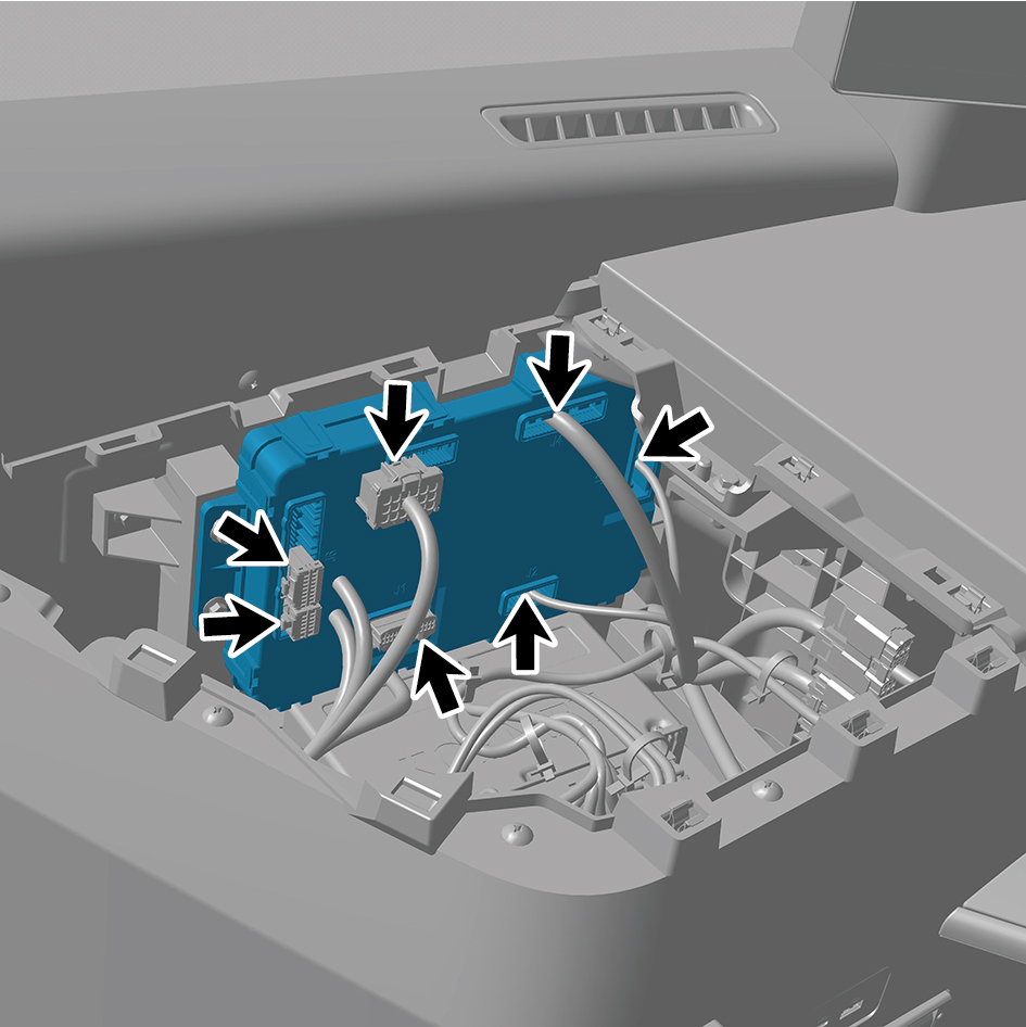
6
Remove 4 fixing bolts of the BCM, and remove the BCM.
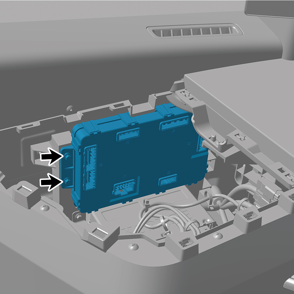
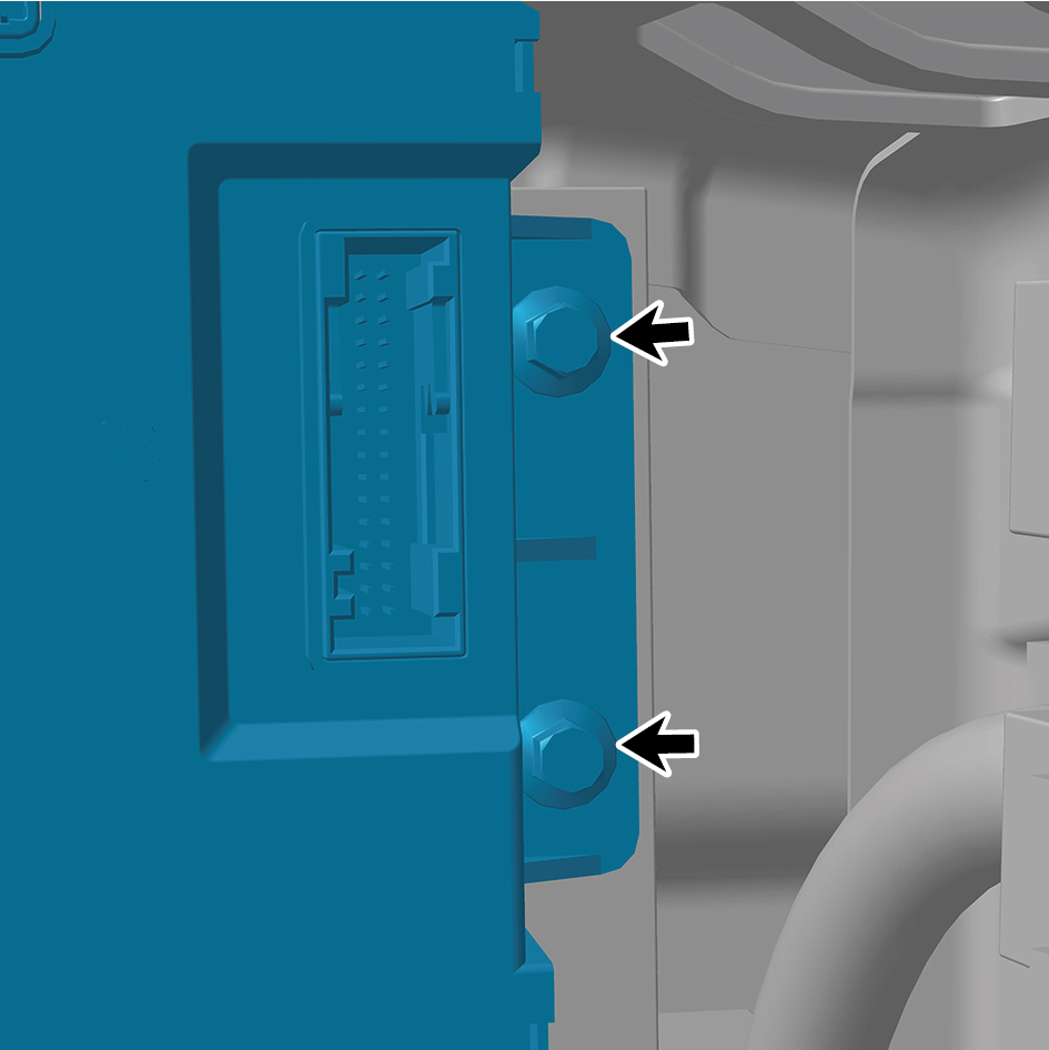
Installation Procedures
1
Move the BCM to the mounting position.
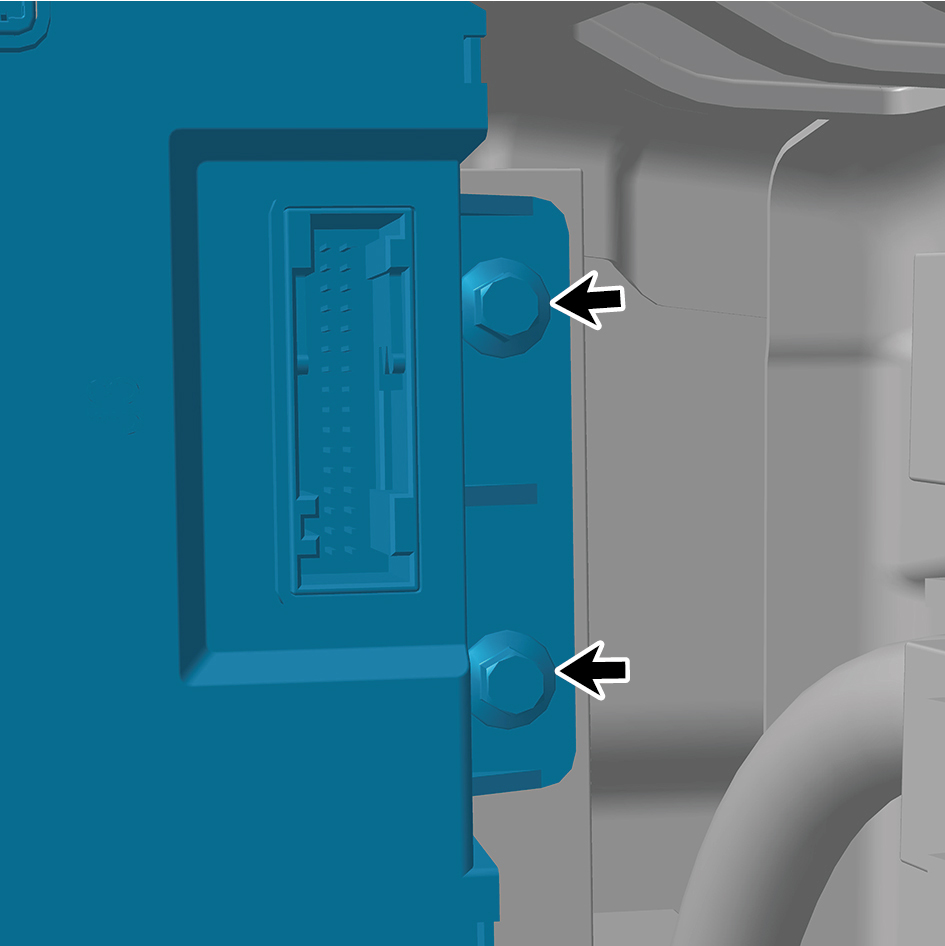
2
Install 4 fixing bolts of the BCM.
Torque:(6.5 +/- .75) ft lbs
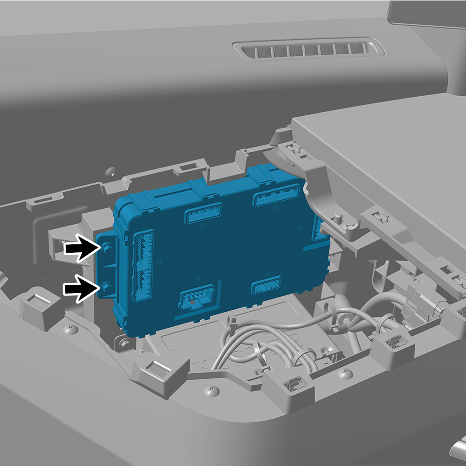
3
Connect 7 harness connectors of the BCM.
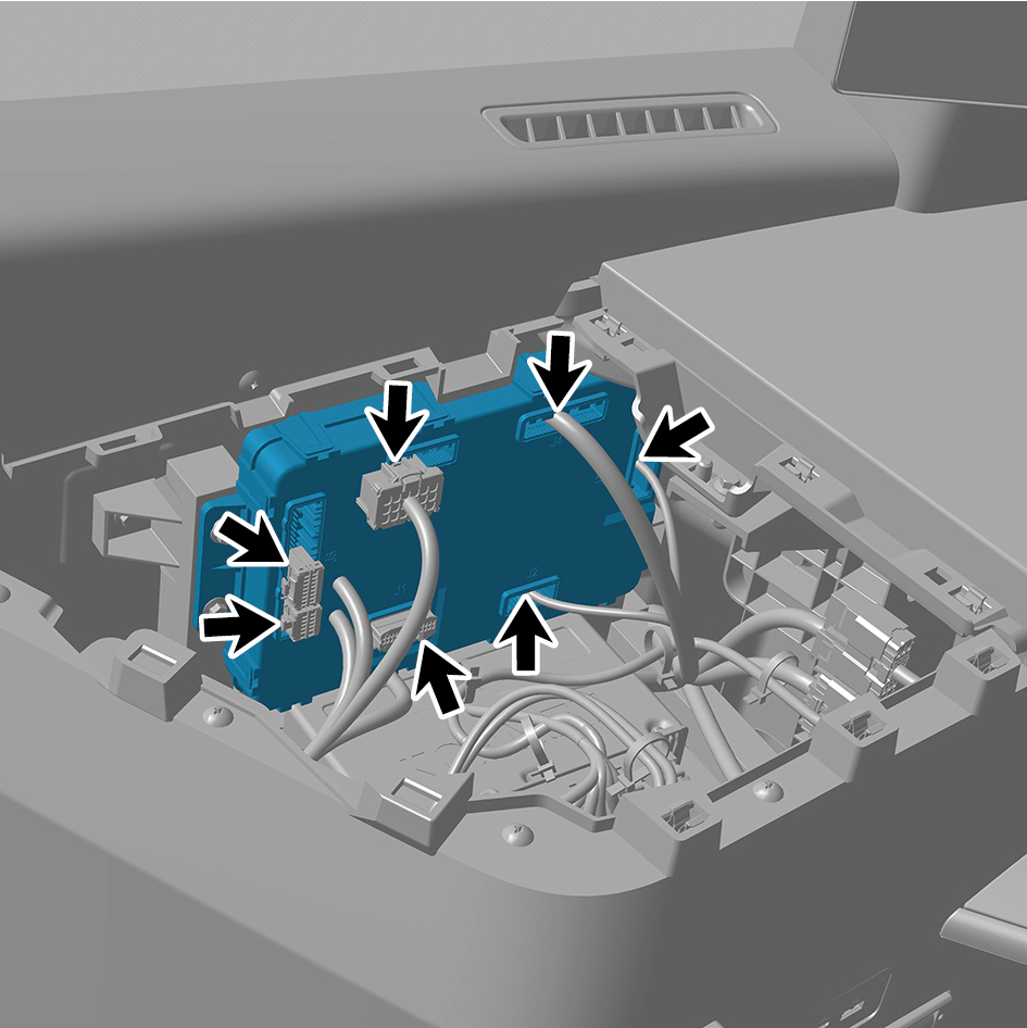
caution
The harness is firmly connected following the
principal of "insert until a click is heard for
confirmation".
4
Install the IP left upper trim panel assembly.
5
Connect the battery negative cable.
6
Close the front flip cover plate.
7
Close the door.
caution
After replacing the BCM, it is necessary to connect a
scan tool for flashing, read VIN, and write the
configuration word.
7.8.6.2 Replacement of Pillar Lock
Removal Procedures
1
Open the door.
2
Open the front flip cover plate.
3
Disconnect the battery negative cable.
caution
power down the high-voltage system before
disconnecting the negative pole of the storage
battery.
4
Remove the combination switch upper shield assembly.
5
Remove the combination switch lower shield.
6
Disconnect 1 harness connector of the pillar lock.
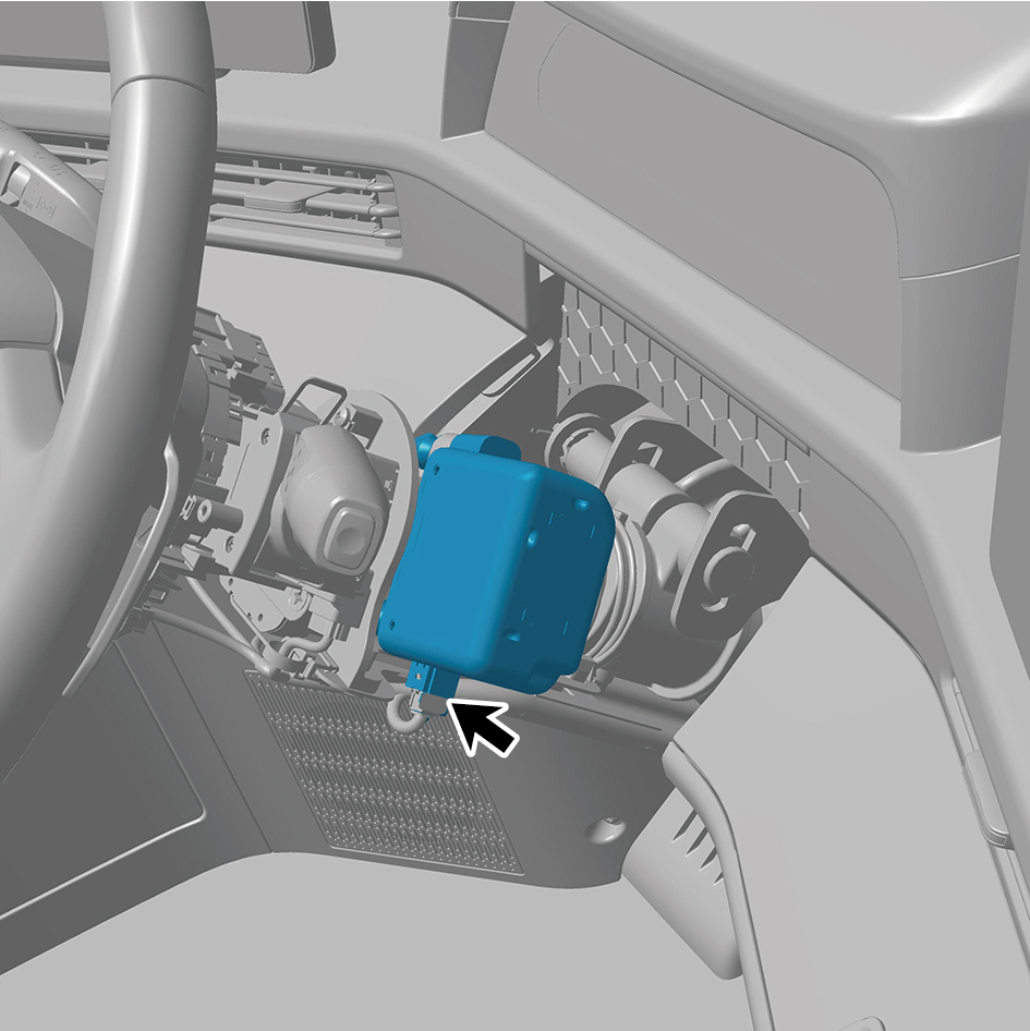
7
Drill one hole on the anti-theft bolt using a drill bit with a
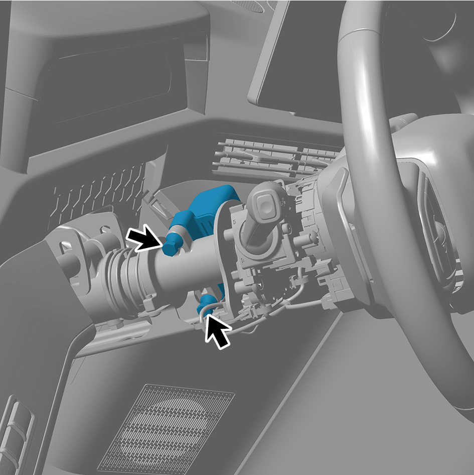
diameter of (3-4) mm.
8
Remove 2 anti-theft bolts with a screw extractor.
9
Remove the pillar lock.
Installation Procedures
1
Move the pillar lock to the mounting position.
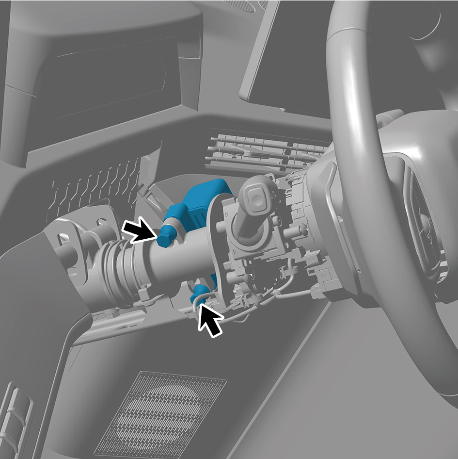
2
Install 2 anti-theft bolts of the pillar lock.
Torque: (17 +/- 2) ft lbs
3
Connect 1 harness connector of the pillar lock.
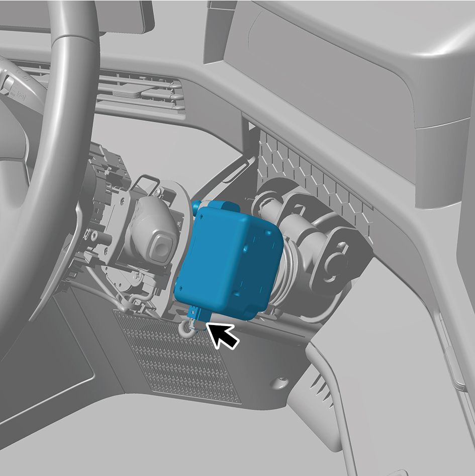
caution
The harness is firmly connected following the
principal of "insert until a click is heard for
confirmation".
4
Install the combination switch lower shield.
5
Install the combination switch upper shield assembly.
6
Connect the battery negative cable.
7
Close the front flip cover plate.
8
Close the door.
caution
The anti-theft bolt is a disposable part and shall not
be reused.
When reinstalling the pillar lock, the anti-theft bolt
needs to be replaced with a new one, and the upper
part of the anti-theft bolt needs to be twisted off
during installation.
7.8.6.3 Replacement of NFC Antenna
Removal Procedures
1
Open the door.
2
Open the front flip cover plate.
3
Disconnect the battery negative cable.
caution
power down the high-voltage system before
disconnecting the negative pole of the storage
battery.
4
Remove the IP right upper trim panel assembly.
5
Disconnect 1 harness connector of the NFC antenna.
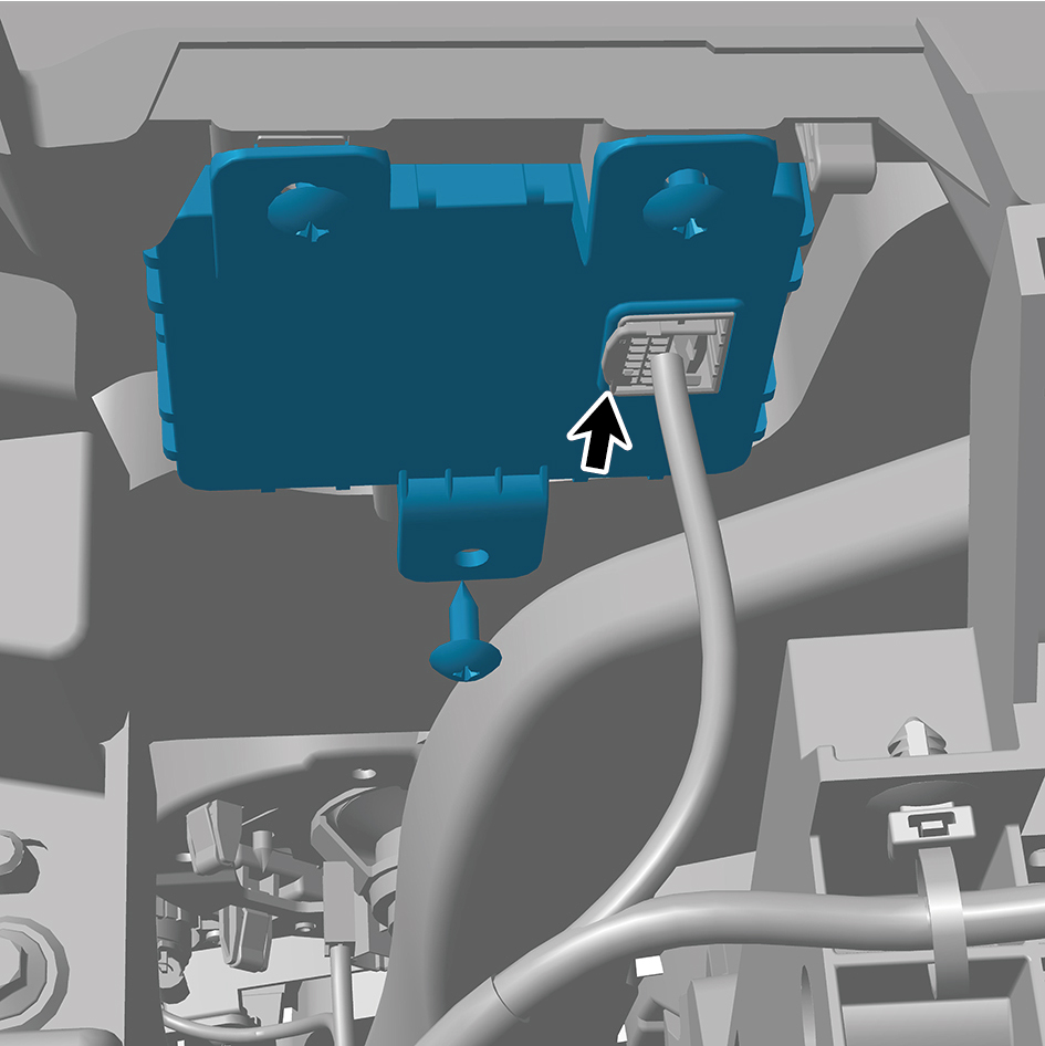
6
Remove 3 fixing screws of the NFC antenna.
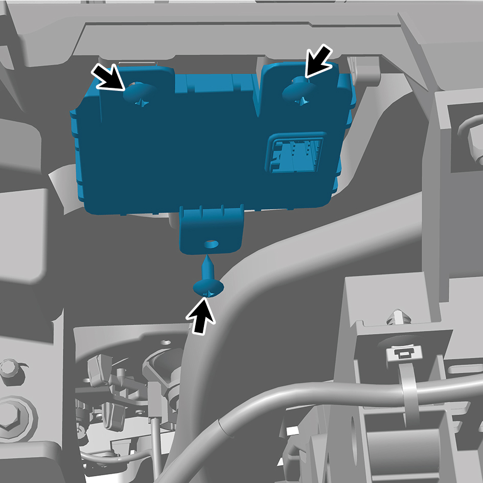
7
Remove the NFC antenna.
Installation Procedures
1
Move the NFC antenna to the mounting position.
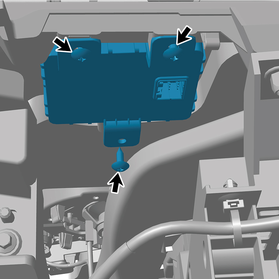
2
Install 3 fixing screws of the NFC antenna.
3
Connect 1 harness connector of the NFC antenna.
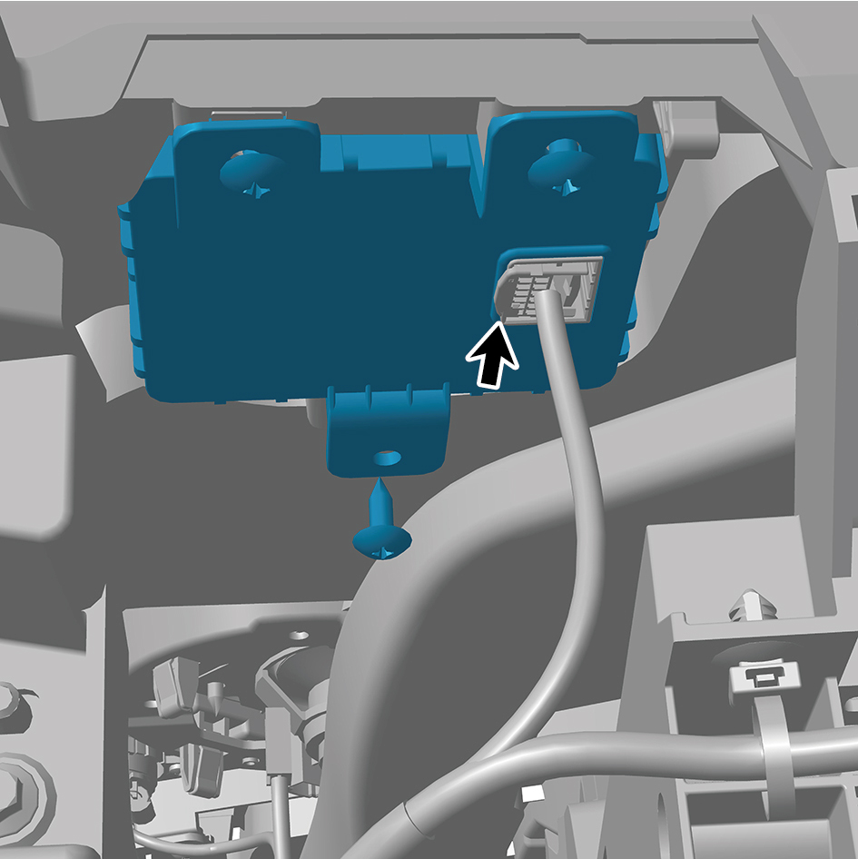
caution
The harness is firmly connected following the
principal of "insert until a click is heard for
confirmation".
4
Install the IP right upper trim panel assembly.
5
Connect the battery negative cable.
6
Close the front flip cover plate.
7
Close the door.
7.8.6.4 Replacement of Wireless Charging Module
Module
Removal Procedures
1
Open the door.
2
Open the front flip cover plate.
3
Disconnect the battery negative cable.
caution
power down the high-voltage system before
disconnecting the negative pole of the storage
battery.
4
Remove the IP right upper trim panel assembly.
5
Remove 4 fixing screws of the wireless charging module
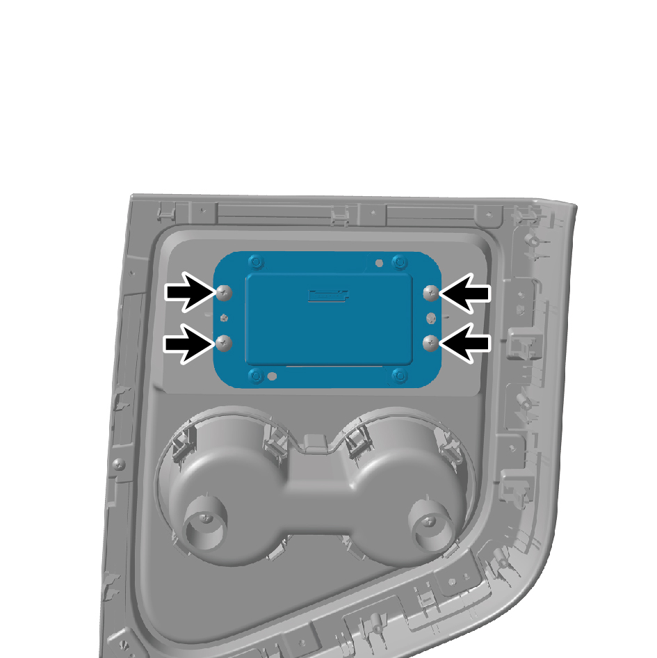
with a bracket.
6
Remove 4 fixing bolts of the wireless charging module.
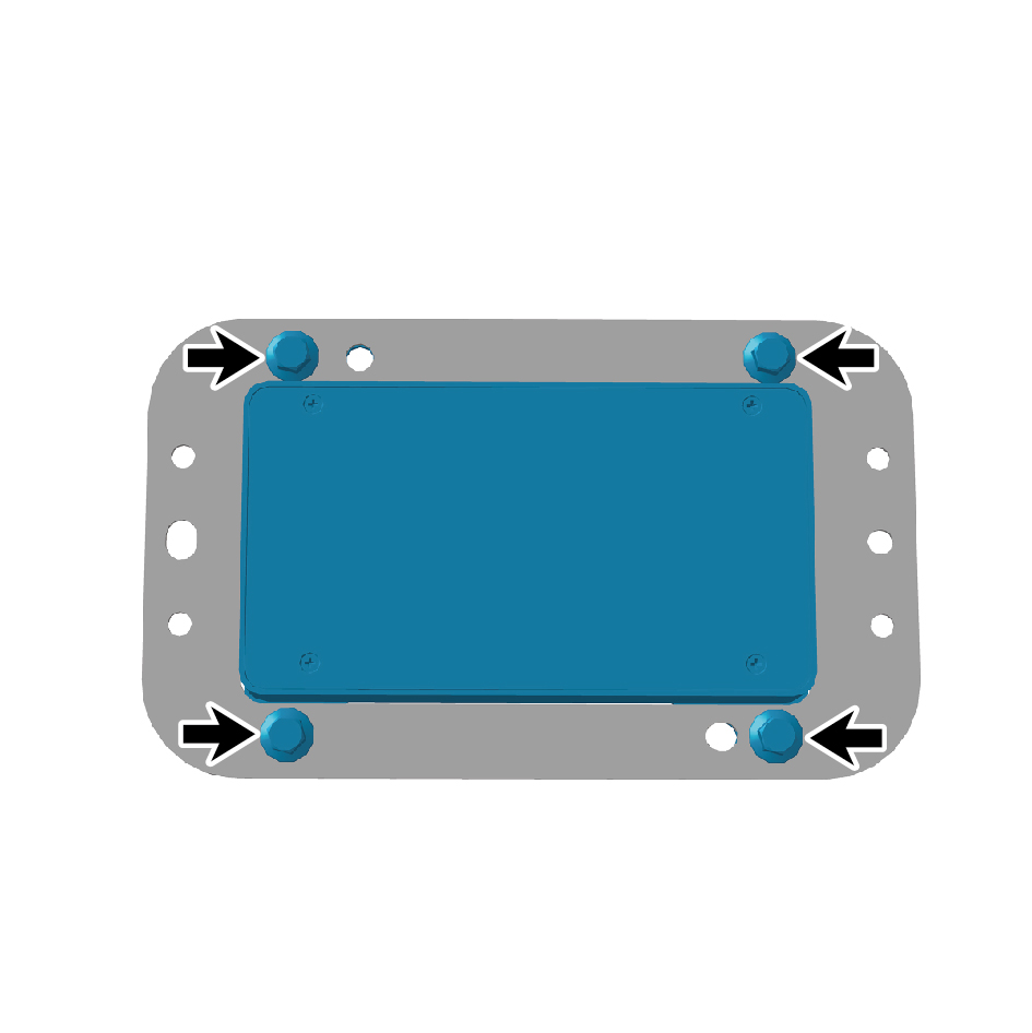
7
Remove the wireless charging module.
Installation Procedures
1
Move the wireless charging module to the mounting
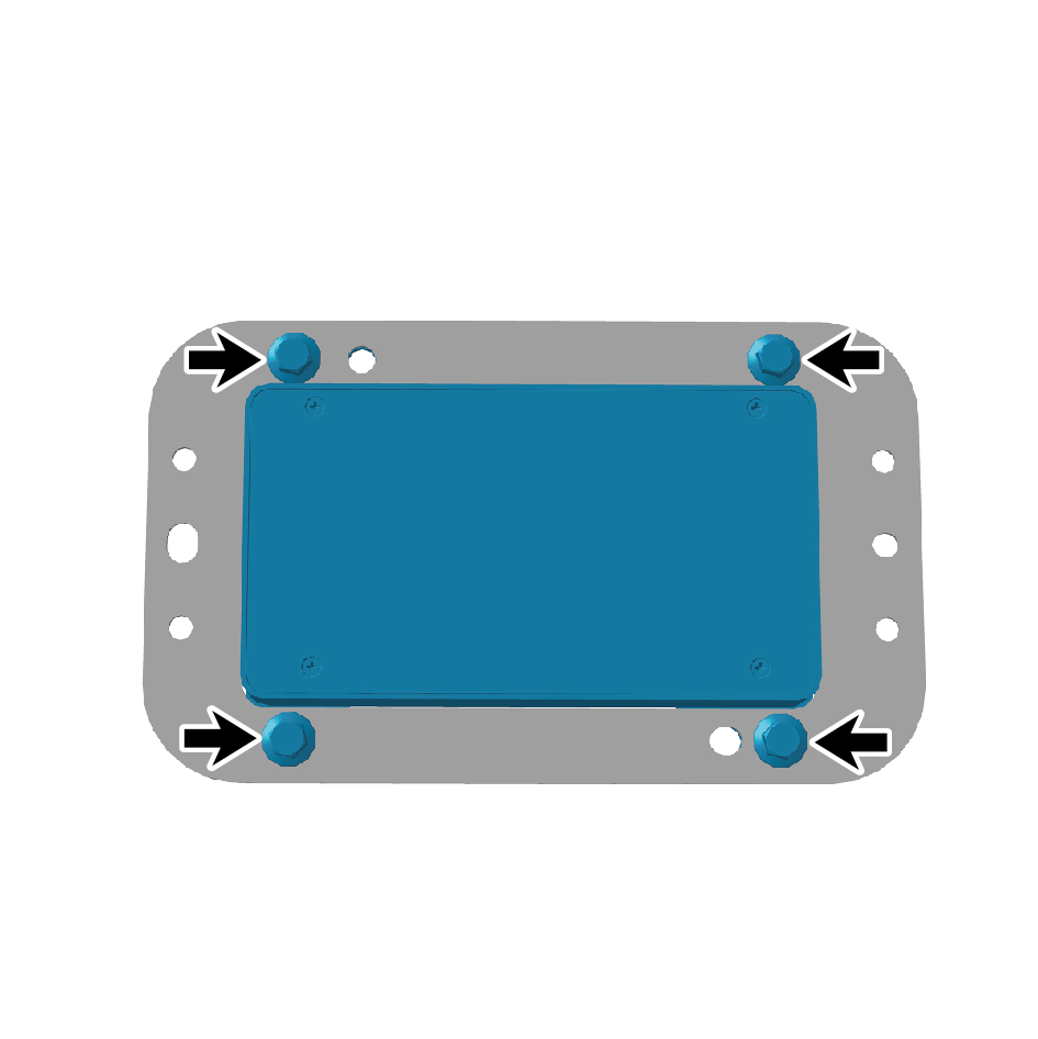
position.
2
Install 4 fixing bolts of the wireless charging module.
Torque:(4.5 +/- .75) ft lbs
3
Install 4 fixing screws of the wireless charging module with
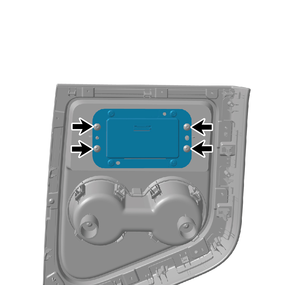
a bracket.
4
Install the IP right upper trim panel assembly.
5
Connect the battery negative cable.
6
Close the front flip cover plate.
Close the door.
7.8.6.5 Replacement of DCM
Removal Procedures
1
Open the door.
2
Open the front flip cover plate.
3
Disconnect the battery negative cable.
caution
power down the high-voltage system before
disconnecting the negative pole of the storage
battery.
4
Remove the right sill molding assembly.
5
Remove the door opening sealing strip assembly.
6
Remove the safety hammer fixing bracket.
7
Remove the rear boarding handrail assembly.
8
Remove the SSM.
9
Remove the right rear side wall protective plate assembly.
10
Disconnect 3 harness connector of the DCM.
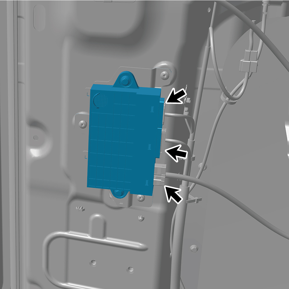
11
Remove 2 fixing bolts of the DCM.
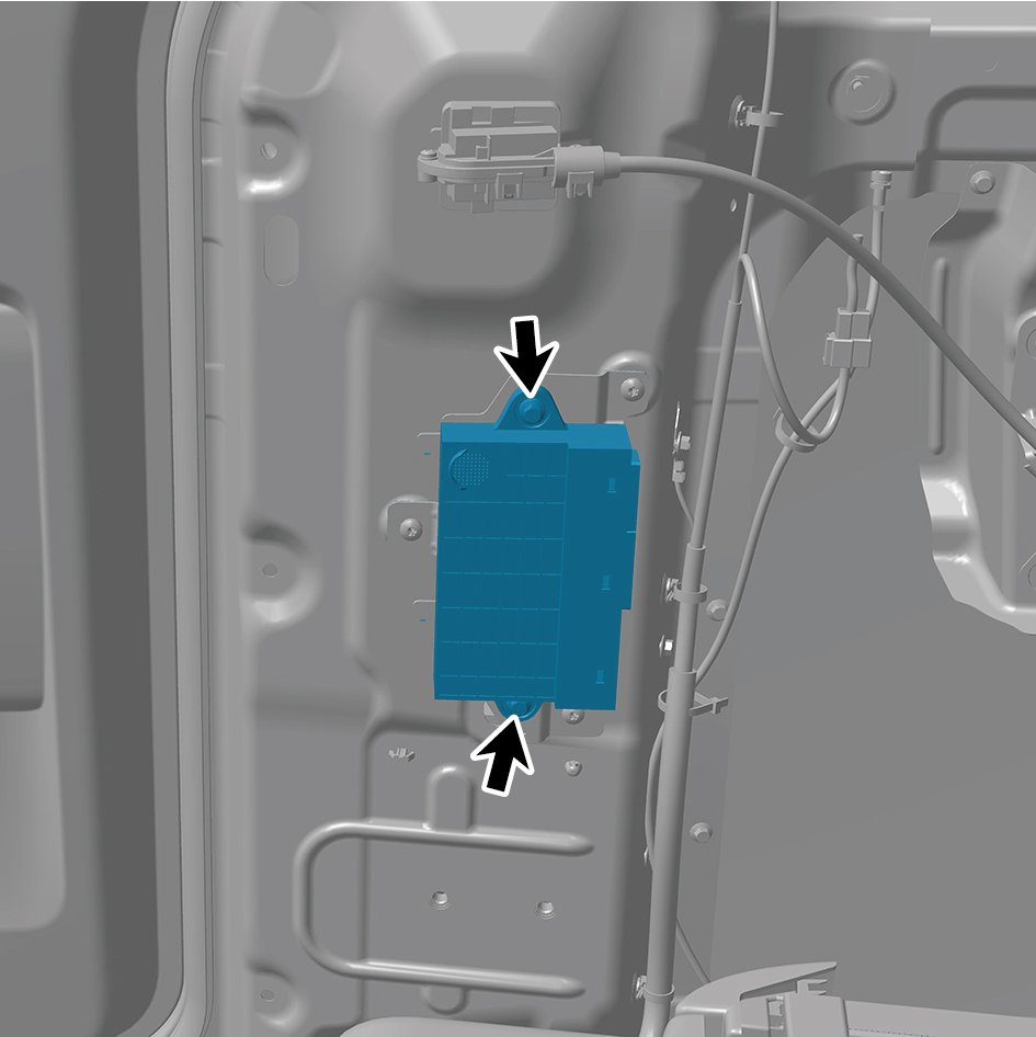
12
Remove the DCM.
Installation Procedures
1
Move the DCM to the mounting position.
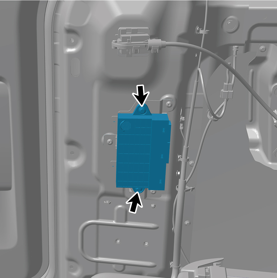
2
Install 2 fixing bolts of the DCM.
Torque: (6.5 +/- .75) ft lbs
3
Connect 3 harness connector of the DCM.
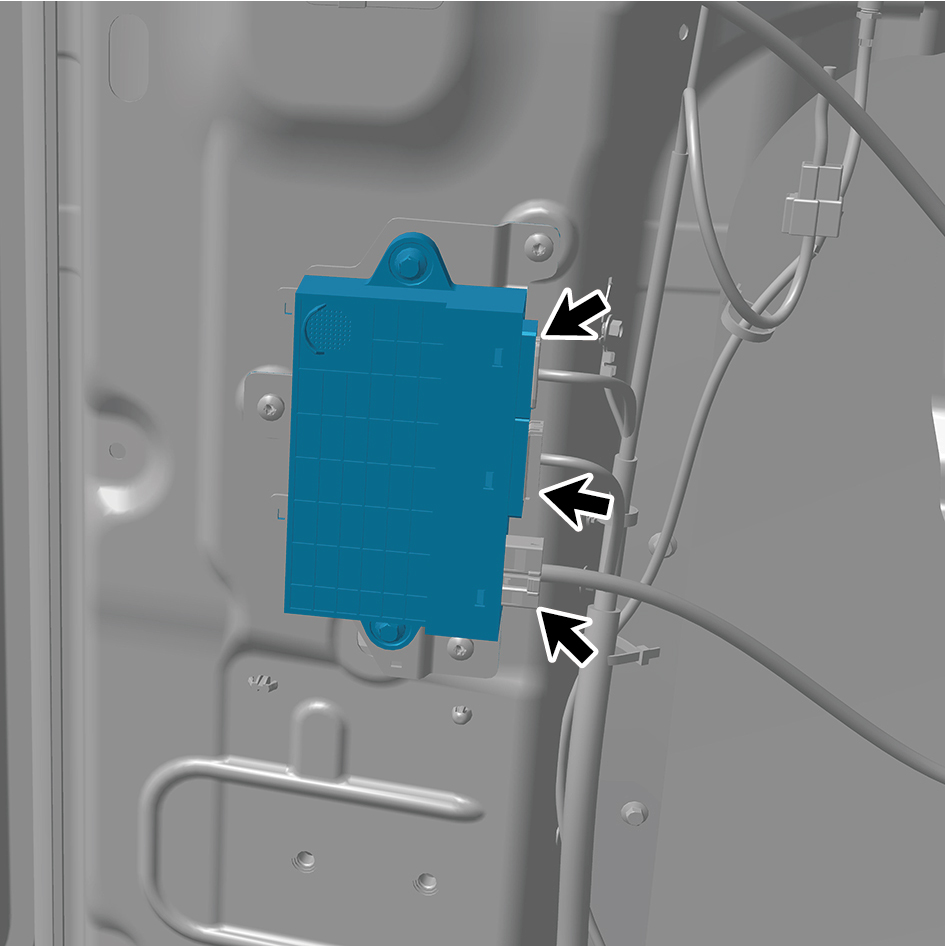
caution
The harness is firmly connected following the
principal of "insert until a click is heard for
confirmation".
4
Install the right rear side wall protective plate assembly.
5
Install the SSM.
6
Install the rear boarding handrail assembly.
7
Install the safety hammer fixing bracket.
8
Install the door opening sealing strip assembly.
9
Install the right sill molding assembly.
10
Connect the battery negative cable.
11
Close the front flip cover plate.
12
Close the door.
caution
After replacing the DCM, it is necessary to connect
a scan tool for flashing.