← Back to Contents
7 Automotive Electrical Appliances / 7.7 Switch Device | PDF pages 1514-1541
7.7 Switch Device
7.7 Switch Device
7.7.1 Decomposition Diagram
7.7.1.1 Decomposition Diagram
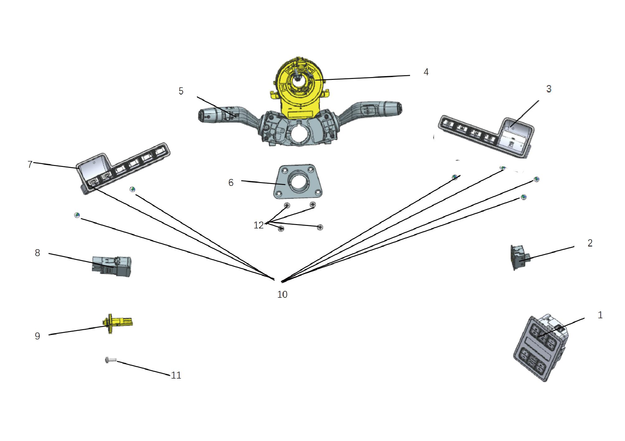
7.
1.
Sleeper Switch Devices
Lh Switch Group at Instrument Panel
2.
9.
Power Sliding Door
Switch-Locker Lighting
3.
10.
Rh Switch Group at Instrument Panel
Self-Tapping Screw
4.
11.
Clock-Spring
Hex Socket Set Screw
5.
12.
Multi-Function Switch
Hex Socket Set Screw
6.
Multi-Function Switch Bracket
7.7.2 System Schematic Diagram
7.7.2.1 Electrical Schematic Diagram
Right combination switch - gear position
Sleeper switch devices
7.7.3 Diagnostic Information and Steps
7.7.3.1 Diagnostic Description
Before diagnosing faults in the switch device, it is important to understand and familiarize oneself with the working principle of the
switch device before starting the system diagnosis. This will help determine the correct fault diagnosis steps when a fault occurs,
and more importantly, it will help determine the situation described by the customer belongs to normal operation. Any fault
diagnosis of switch devices should start with routine inspection, guiding maintenance personnel to take the next logical step for
fault diagnosis. Understanding and correctly using the diagnostic process can shorten the diagnosis time and avoid misjudgment
of faulty parts.
7.7.3.2 Routine Inspection
• Check for aftermarket installation devices that may affect the operation of the switchgear system, ensuring that these devices
do not affect the operation of the switchgear system.
• Check system components that are easily accessible or visible to ensure that there is no obvious damage or potential
malfunction.
7.7.3.3 Fault Symptom Table
Symptom
Suspected Faulty Project
Measures
Check the gear shift switch and replace
1.Shift switch stuck or damaged
it if necessary. Refer to Replacement Of
The vehicle cannot shift gears
Combination Switch
2. Shift switch malfunction
Refer to Shift Switch Power Failure
7.7.3.4 DTC Confirmation
1. Connect the diagnostic tool to the diagnostic interface, read and record the DTC, and then clear the DTC.
2. Run the vehicle again.
3. Read the fault code of the control system again to confirm if there is any fault code output from the system.
– Yes:Diagnose based on the output fault code.
– No:Perform intermittent fault check, refer to Inspection Of Intermittent Faults
7.7.3.5 List Of Diagnostic Trouble Codes (DTC)
GSM
Fault Description
Exclusion Method
Fault Code
Battery voltage is too high
B111717
Refer to Shift Switch Power Fault
Battery voltage is too low
B111716
U008E88
PCAN4 BusOff
U019887
Lost communication with TGW
Refer to Shift Switch Communication
Fault
U015687
Communication with CDCU is lost
U012287
Communication with VDC is lost
P280096
Shift switch sensor malfunction
Refer to Shift Switch Internal Fault
Gear shift lever jamming failure
P280171
SSM
Fault Description
Exclusion Method
Fault Code
Power supply voltage below threshold
B111716
Refer to Sleeper Switch Devices Power
Fault
Power supply voltage above threshold
B111717
Fault Description
Exclusion Method
Fault Code
U007E88
BCANFD3 BusOff
U019887
lost communication with T-BOX
U014087
lost communication with BDCU
U016487
lost communication with A/C
Refer to Sleeper Switch Devices
Communication Fault
U015687
lost communication with CDCU
U012287
lost communication with VDC
CANFD3 network management limp
U220A00
home
7.7.3.6 Shift Switch Power Fault
1. DTC Monitoring Logic
Description
DTC Trigger Conditions
Faulty Part
DTC Code
Battery voltage is too
1. Main battery
Voltage > 32V, t > 2000ms
B111717
high
2. Low voltage
charging system
Battery voltage is too
3. Wiring harness
Voltage < 18V, t > 2000ms
B111716
low
4.Shift switch
2.Circuit Diagram
Smart Junction Box - Chassis
Battery
B12-1
C4-21
Total body power
Middle and rear axle MCU-KL30 O421
supply B+ L22
VDC-1
BDCU-4
B48-26
C93-97
status feedback H01
Smart Junction
Differential lock
Box - Body
B01-1
MCU4-CAN
drive wake up the power supply E146
The PDU, TCU, middrive, and rear
B07-2
B07-16
switch/parking
power supply
Switch class
KL30 shift
switch P116
36
I7_B_C
KL15 Power
supply P102
36
I7_C_B
switch - Shift
Combination
-KL30 P116b
Differential lock feedback signal
MCU power supply KL30 O421b
30
I1_B_IP
12
I1_B_IP
H01b
MCU4-CAN-H PH04e
MCU4-CANL PL04e
30
I1_IP_B
12
I1_IP_B
switch - Shift
KL15 Power
Combination
-KL30 P116b
supply P102
KL15 Power
Power KL30
supply P102a
C25-17
C25-1
C25-13
C25-5
C25-6
P116b
E-axle rear axle vehicle low voltage port
IP18-3
IP18-9
C25-20
C25-3
C25-4
MCU3-CAN-H PH04h
MCU3-CAN-L PL04h
MCU3-CAN-H PH04f
MCU3-CANL PL04f
MCU Power Supply - Z66
Shift switch
120Ω
IP18-8
IP18-2
IP18-1
PCAN4-H PH04d
PCAN4-L PL04d
Ground Z12d
C114-2
C114-1
CAN resistance -120Ω
MCU3-CAN
G02
G14
PCAN4
3. Diagnostic Steps
Step 1:DTC confirmation. Refer to DTC Confirmation
Step 2:Routine inspection. Refer to Routine Inspection
Step 3:Check if there are any other module power fault codes besides the shift switch?
Check the main battery. Refer to Inspection Of The Main Battery
– Yes:
Check the low-voltage charging system. Refer to DCDC1 Low-voltage Charging System Fault
Next step
– No:
Step 4:Check the power supply and grounding harness of the gear shift switch.
Step 5:Rewrite the configuration code for the gear shift switch, reload the software, and upgrade.
Step 6:Replace the gear shift switch. Refer to Replacement Of Combination Switch
Step 7:Clear and confirm DTC.
7.7.3.7 Shift Switch Communication Fault
1. DTC Monitoring Logic
Description
DTC Trigger Conditions
Faulty Part
DTC Code
1.BUSOFF lasts more than 8 times
U008E88
PCAN4 BusOff
2.The current voltage is 18~32V
1.KL15 ON;
2.The current voltage is 18~32V
Lost communication
U019887
3.When GSM loses communication with TGW
with TGW
(0x18FEE6EEx) for more than 5000ms, GSM sets the
current DTC
1. Wiring harness
1.KL15 ON;
2. Shift switch
2.The current voltage is 18~32V
Communication with
U015687
3.When GSM loses communication with CDCU
CDCU is lost
(0x18FEC1EEx) for more than 5000 ms, GSM sets the
current DTC
1.KL15 ON;
2.The current voltage is 18~32V 3.When GSM loses
Communication with
U012287
communication with VDC (0x18FEF100x) for more than
VDC is lost
1000 ms, GSM sets the current DTC
2.Circuit Diagram
Smart Junction Box - Chassis
Battery
B12-1
C4-21
Total body power
Middle and rear axle MCU-KL30 O421
supply B+ L22
VDC-1
BDCU-4
B48-26
C93-97
status feedback H01
Smart Junction
Differential lock
Box - Body
B01-1
MCU4-CAN
drive wake up the power supply E146
The PDU, TCU, middrive, and rear
B07-2
B07-16
switch/parking
power supply
Switch class
KL30 shift
switch P116
36
I7_B_C
KL15 Power
supply P102
36
I7_C_B
switch - Shift
Combination
-KL30 P116b
Differential lock feedback signal
MCU power supply KL30 O421b
30
I1_B_IP
12
I1_B_IP
H01b
MCU4-CAN-H PH04e
MCU4-CANL PL04e
30
I1_IP_B
12
I1_IP_B
switch - Shift
KL15 Power
Combination
-KL30 P116b
supply P102
KL15 Power
Power KL30
supply P102a
C25-17
C25-1
C25-13
C25-5
C25-6
P116b
E-axle rear axle vehicle low voltage port
IP18-3
IP18-9
C25-20
C25-3
C25-4
MCU3-CAN-H PH04h
MCU3-CAN-L PL04h
MCU3-CAN-H PH04f
MCU3-CANL PL04f
MCU Power Supply - Z66
Shift switch
120Ω
IP18-8
IP18-2
IP18-1
PCAN4-H PH04d
PCAN4-L PL04d
Ground Z12d
C114-2
C114-1
CAN resistance -120Ω
MCU3-CAN
G02
G14
PCAN4
3. Diagnostic Steps
Step 1:DTC confirmation. Refer to DTC Confirmation
Step 2:Routine inspection. Refer to Routine Inspection
Step 3:Check the PCAN4 bus communication harness. Refer to Inspection Of PCAN4 Bus Network Integrity
Step 4:Rewrite the configuration code for the gear shift switch, reload the software, and upgrade.
Step 5:Replace the gear shift switch. Refer to Replacement Of Combination Switch
Step 6:Clear and confirm DTC.
7.7.3.8 Shift Switch Internal Fault
1. DTC Monitoring Logic
Description
DTC Trigger Conditions
Faulty Part
DTC Code
1.Gear sensor failure lasts for 3S
Shift switch sensor
P280096
2.The current voltage is 18~32V
malfunction
1.Shift switch
1.The gear stays in a non-default position for 60
Gear shift lever
seconds
P280171
jamming failure
2.The current voltage is between 18 and 32V
2. Diagnostic Steps
Step 1:DTC confirmation. Refer to DTC Confirmation
Step 2:Routine inspection. Refer to Routine Inspection
Step 3:Rewrite the configuration code for the gear shift switch, reload the software, and upgrade.
Step 4:Replace the gear shift switch. Refer to Replacement Of Combination Switch
Step 5:Clear and confirm DTC.
7.7.3.9 Sleeper Switch Devices Power Fault
1. DTC Monitoring Logic
Description
DTC Trigger Conditions
Faulty Part
DTC Code
Low Battery Voltage
Voltage < 18V, t > 500ms
1. Main battery
B111716
2. Low voltage
charging system
3. Wiring harness
High battery voltage
Voltage > 32V, t > 500ms
B111717
4.Sleeper switch
devices
2.Circuit Diagram
3. Diagnostic Steps
Step 1:DTC confirmation. Refer to DTC Confirmation
Step 2:Routine inspection. Refer to Routine Inspection
Step 3:Check if there are any other module power fault codes besides the sleeper switch devices?
Check the main battery. Refer to Inspection Of The Main Battery
– Yes:
Check the low-voltage charging system. Refer to Inspection Of The Main Battery
Next step
– No:
Step 4:Check the power and grounding harnesses of the sleep switch devices.
Step 5:Sleep switch devices rewrite configuration code, software reload, upgrade.
Step 6:Replace the sleeper switch devices. Refer to Replacement Of Sleep Switch Devices
Step 7:Clear and confirm DTC.
7.7.3.10 Sleeper Switch Devices Communication Fault
1. DTC Monitoring Logic
Description
DTC Trigger Conditions
Faulty Part
DTC Code
eight times in a row
U007E88
BCANFD3 BusOff
Lost Communication
0x18FEE6EE(T>50ms:5*T;or else:250ms)
U019887
With T-Box
lost communication
0x14FD1721(T>50ms:5*T;or else:250ms)
U014087
with BDCU
lost communication
0x18FF2419(T>50ms:5*T;or else:250ms)
1. Wiring harness
U016487
with A/C
2.Sleeper switch
Lost Communication
devices
0x18FEC1EE(T>50ms:5*T;or else:250ms)
U015687
With CDCU
Lost Communication
0x18FEF100(T>50ms:5*T;or else:250ms)
U012287
With VDC
CANFD3 network
2 seconds in limphome state
U220A00
management limp
home
2.Circuit Diagram
3. Diagnostic Steps
Step 1:DTC confirmation. Refer to DTC Confirmation
Step 2:Routine inspection. Refer to Routine Inspection
Step 3:Check the BCANFD3 bus communication harness. Refer to BInspection Of CANFD3 Bus Network Integrity
Step 4:Rewrite the configuration code, reload the software, and upgrade the sleep switch devices.
Step 5:Replace the sleeper switch devices. Refer to Replacement Of Sleep Switch Devices
Step 6:Clear and confirm DTC.
7.7.3.11 Inspection Of PCAN4 Bus Network Integrity
Step 1
Check the PCAN4 bus terminal resistance.
A.
Perform vehicle power on operation.
B.
Do not disconnect the wiring harness connector. Use a
multimeter to measure each terminal according to the
following table:
Measuring Terminals
Standard Value
PCAN4(H) and PCAN4
Resistance:55 - 63 Ω
(L)
C.
Confirm the measured values meet the standards.
Up to step 6.
Yes
Step 2
Check the PCAN4 bus voltage.
A.
Perform vehicle power on operation.
B.
Do not disconnect the wiring harness connector. Use a
multimeter to measure each terminal according to the
following table:
Measuring Terminals
Standard Value
PCAN4 (H) and vehicle
Voltage:2.5 - 3.5 V
grounding
PCAN4 (L) and vehicle
Voltage:1.5 - 2.5 V
grounding
C.
Confirm the measured values meet the standards.
Up to step 6.
Yes
Step 3
Check the bus voltage of each module.
A.
Perform vehicle power on operation.
B.
Measure the bus voltage of each module in sequence
(do not disconnect the harness connectors).
Measuring Terminals
Standard Value
PCAN4 (H) and vehicle
Voltage:2.5 - 3.5 V
grounding
PCAN4 (L) and vehicle
Voltage:1.5 - 2.5 V
grounding
C.
Confirm the bus voltage of each module meets the
standard.
Up to step 6.
Yes
Step 4
Check the power grounding of the communication loss module.
A.
Check the power grounding of the communication loss
module.
B.
Confirm if the module power grounding is normal.
Repair or replace the wiring harness.
Yes
Step 5
Replace the communication loss module.
A.
Replace the communication loss module.
B.
Confirm if the system is functioning properly.
Yes
The system is functioning properly.
Step 6
Check the PCAN4 bus harness.
A.
Perform vehicle power-off operation.
B.
Disconnect all module harness connectors on the
PCAN4 bus.
C.
Measure the PCAN4 bus resistance between each
module and the shift switch in sequence to see if it is
normal.
Standard resistance:less than 1 Ω
D.
Measure the ground resistance of PCAN4 bus is
normal.
Standard resistance:10K Ω or higher
E.
Perform vehicle power on operation.
F.
Measure the PCAN4 bus is short circuited to the power
supply.
Standard voltage:0 V
G.
Confirm the measured values meet the standards.
Repair or replace PCAN4 bus.
Yes
Step 7
Disconnect the modules on the PCAN4 bus in sequence and observe the bus communication voltage/resistance.
Disconnect the modules on the PCAN4 bus in sequence and
observe the bus communication voltage/resistance returns
to normal. If it returns to normal, determine that the
disconnected module is faulty.
7.7.4 Dismantling and Installation
7.7.4.1 Replacement of Left Central Control Switch Group
Switch Group
Removal Procedures
1
Open the door.
2
Open the front flip cover plate.
3
Disconnect the battery negative cable.
caution
power down the high-voltage system before
disconnecting the negative pole of the storage
battery.
4
Remove the left switch panel assembly.
5
Remove 3 fixing screws of the left central control switch
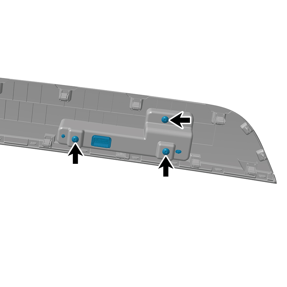
group.
6
Remove the left central control switch group.
Installation Procedures
1
Move the left central control switch group to the mounting
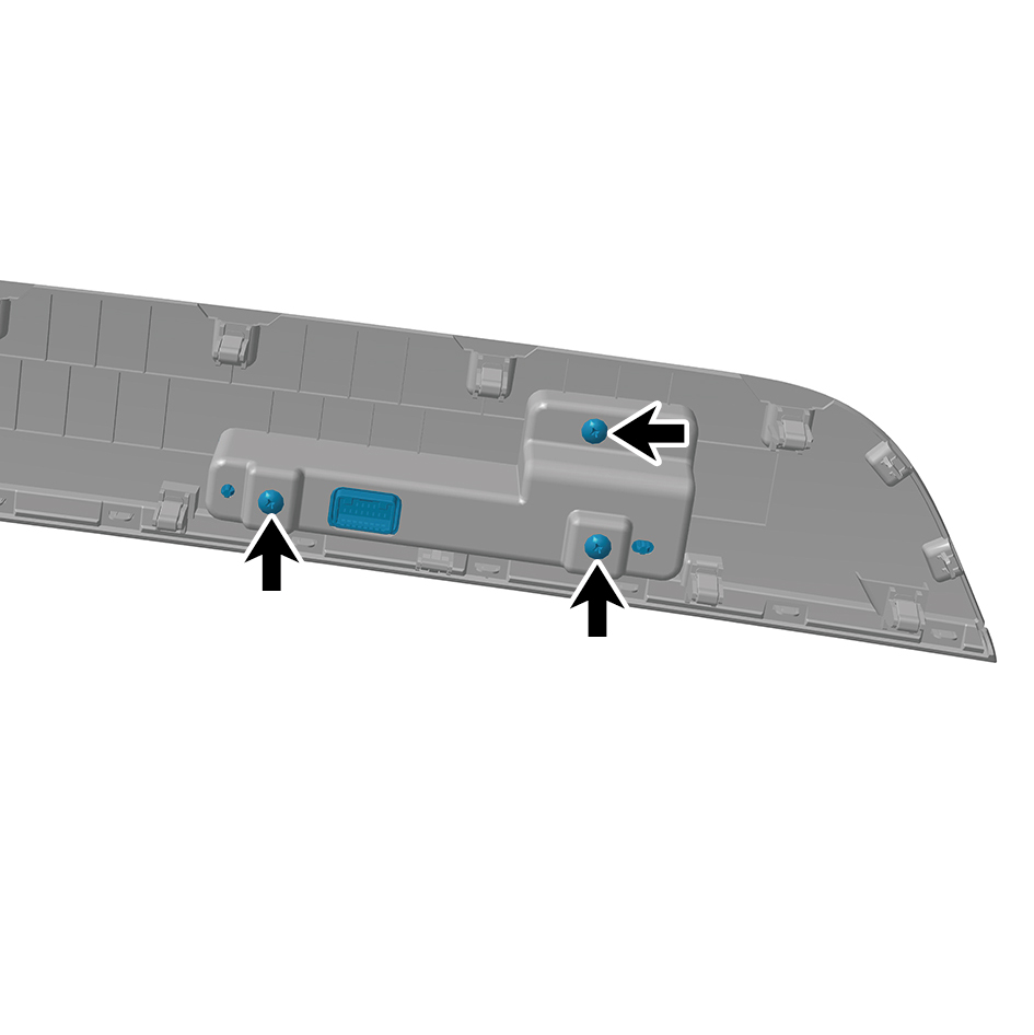
position.
2
Install 3 fixing screws of the left central control switch
group.
3
Install the left switch panel assembly.
4
Connect the battery negative cable.
5
Close the front flip cover plate.
6
Close the door.
7.7.4.2 Replacement of Right Central Control Switch Group
Switch Group
Removal Procedures
1
Open the door.
2
Open the front flip cover plate.
3
Disconnect the battery negative cable.
caution
power down the high-voltage system before
disconnecting the negative pole of the storage
battery.
4
Remove the right switch panel assembly.
5
Remove 4 fixing screws of the right central control switch
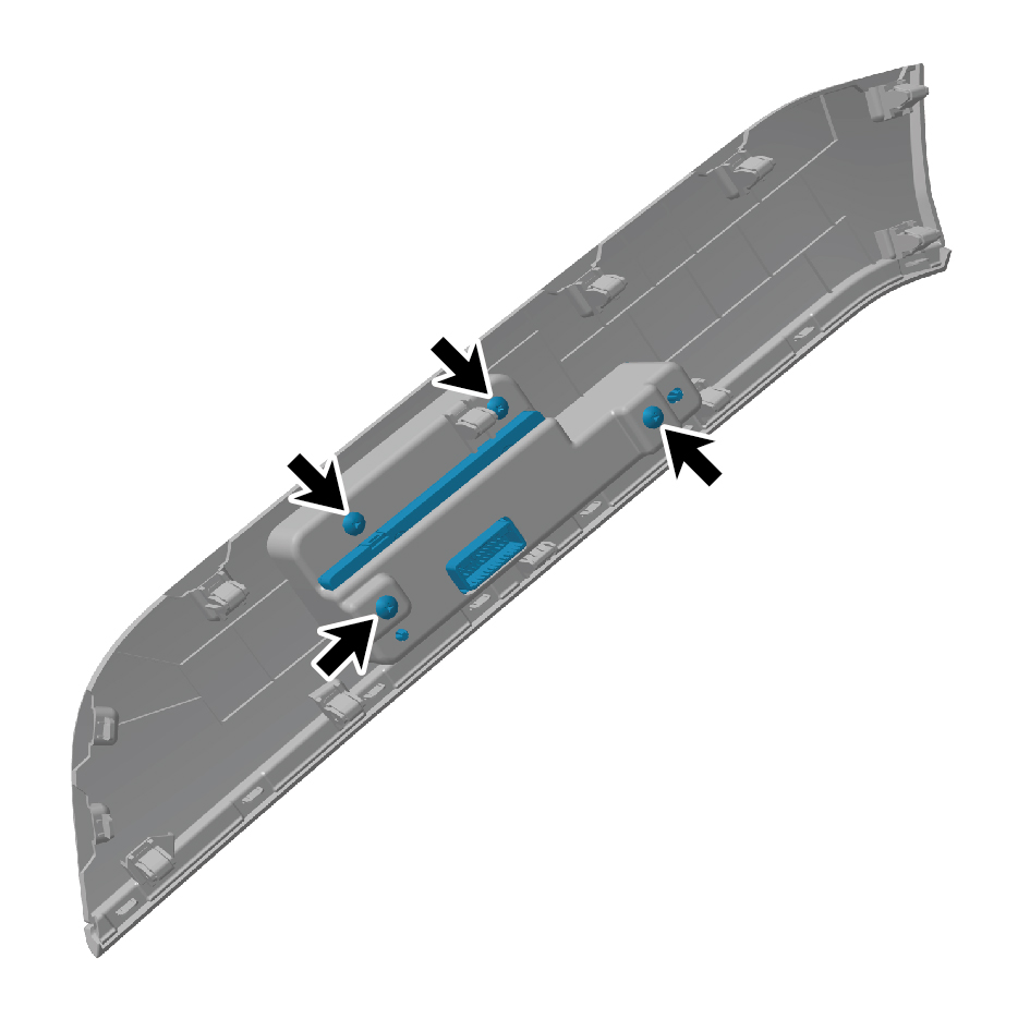
group.
6
Remove the right central control switch group.
Installation Procedures
1
Move the right central control switch group to the
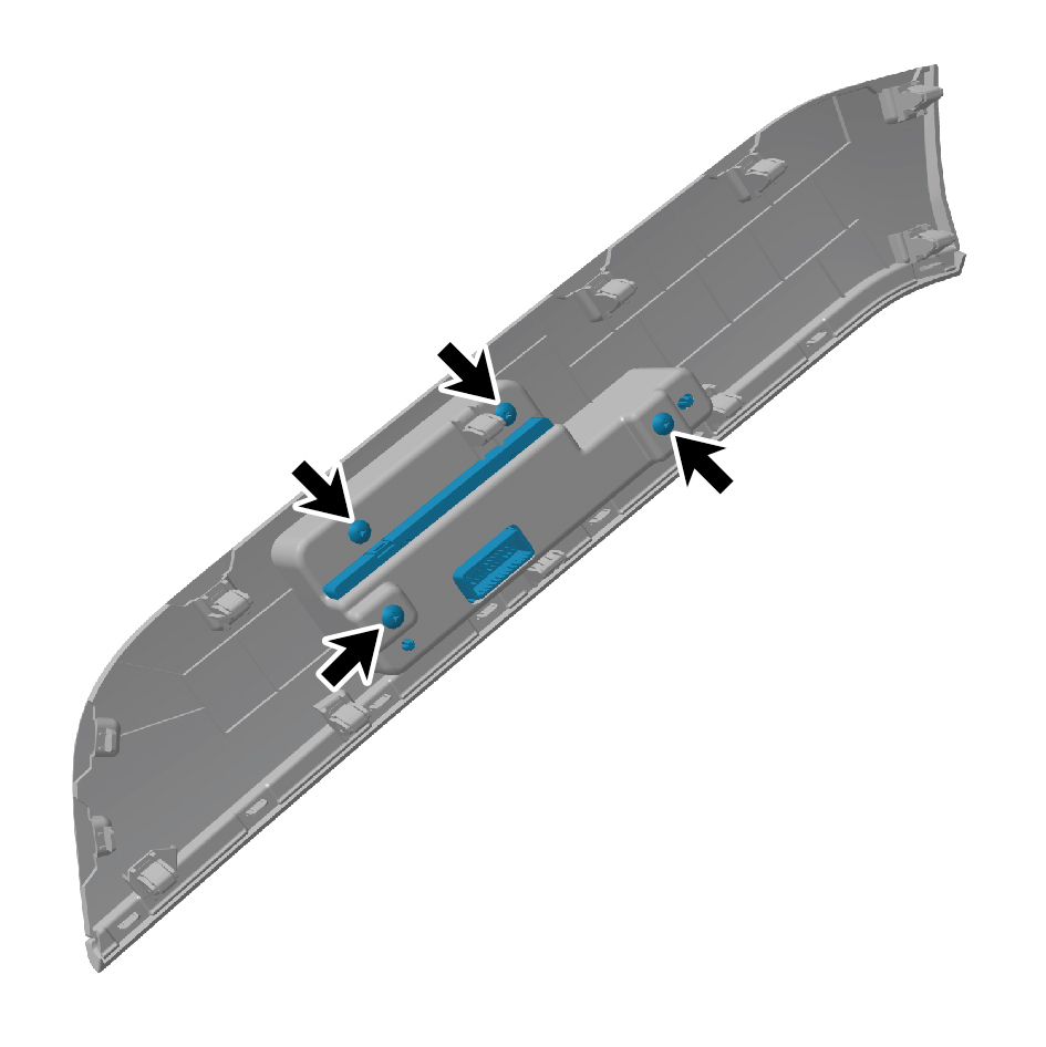
mounting position.
2
Install 4 fixing screws of the right central control switch
group.
3
Install the right switch panel assembly.
4
Connect the battery negative cable.
5
Close the front flip cover plate.
6
Close the door.
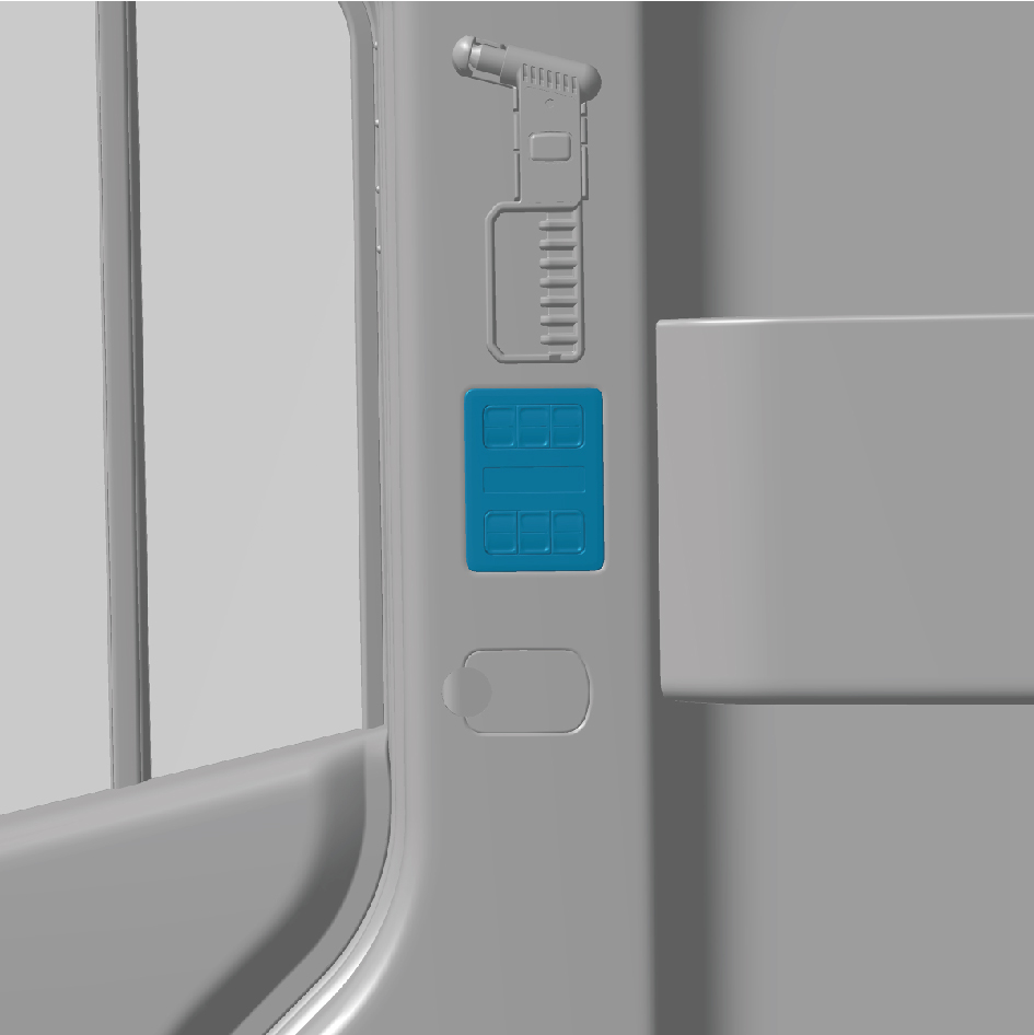
7.7.4.3 Replacement of SSM
Removal Procedures
1
Open the door.
2
Open the front flip cover plate.
3
Disconnect the battery negative cable.
caution
power down the high-voltage system before
disconnecting the negative pole of the storage
battery.
4
Pry off the SSM.
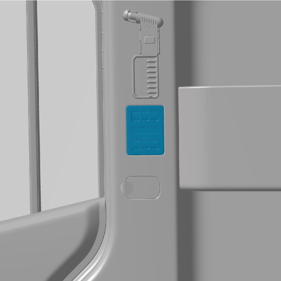
5
Disconnect 1 harness connector of the SSM.
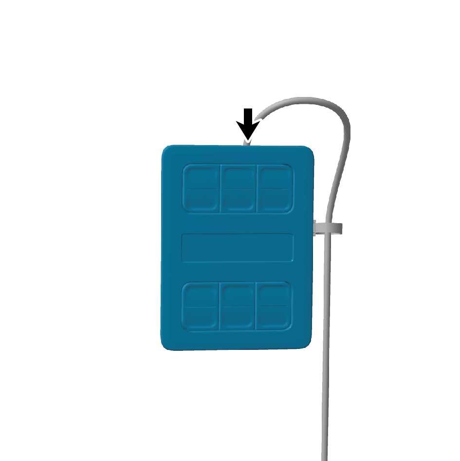
6
Remove the SSM.
Installation Procedures
1
Move the SSM to the mounting position.
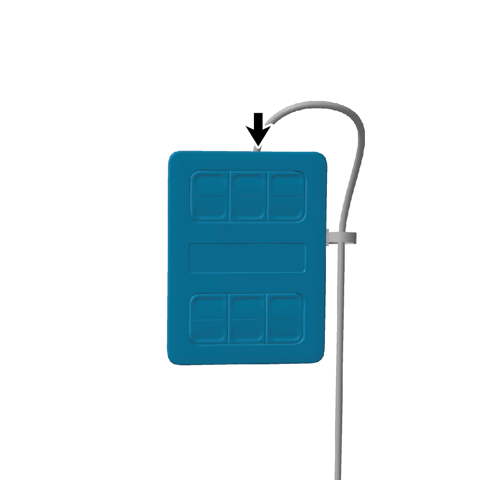
2
Connect 1 harness connector of the SSM.
caution
The harness is firmly connected following the
principal of "insert until a click is heard for
confirmation".
3
Install the SSM.
4
Connect the battery negative cable.
5
Close the front flip cover plate.
6
Close the door.
caution
After part replacement, it is necessary to rewrite the
configuration word.
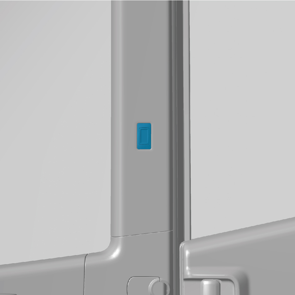
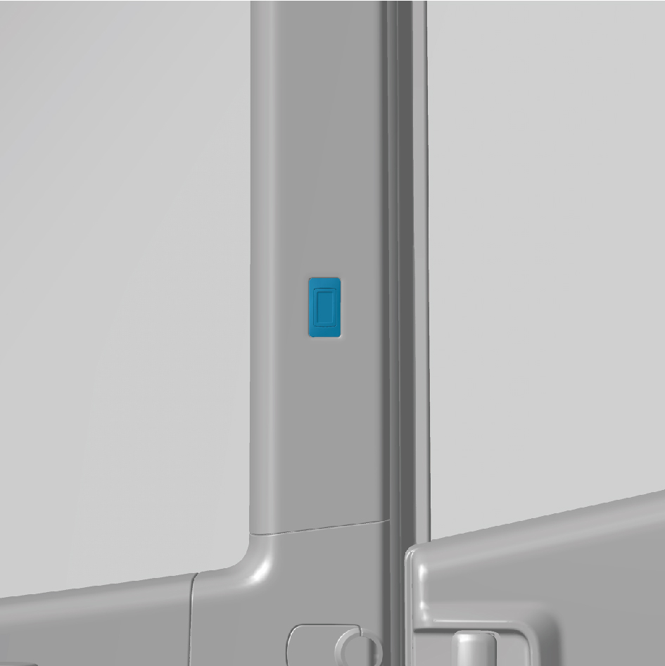
7.7.4.4 Replacement of Electric Sliding Door Switch
Switch
Removal Procedures
1
Open the door.
2
Open the front flip cover plate.
3
Disconnect the battery negative cable.
caution
power down the high-voltage system before
disconnecting the negative pole of the storage
battery.
4
Pry off the electric sliding door switch.
5
Disconnect 1 harness connector of the electric sliding door
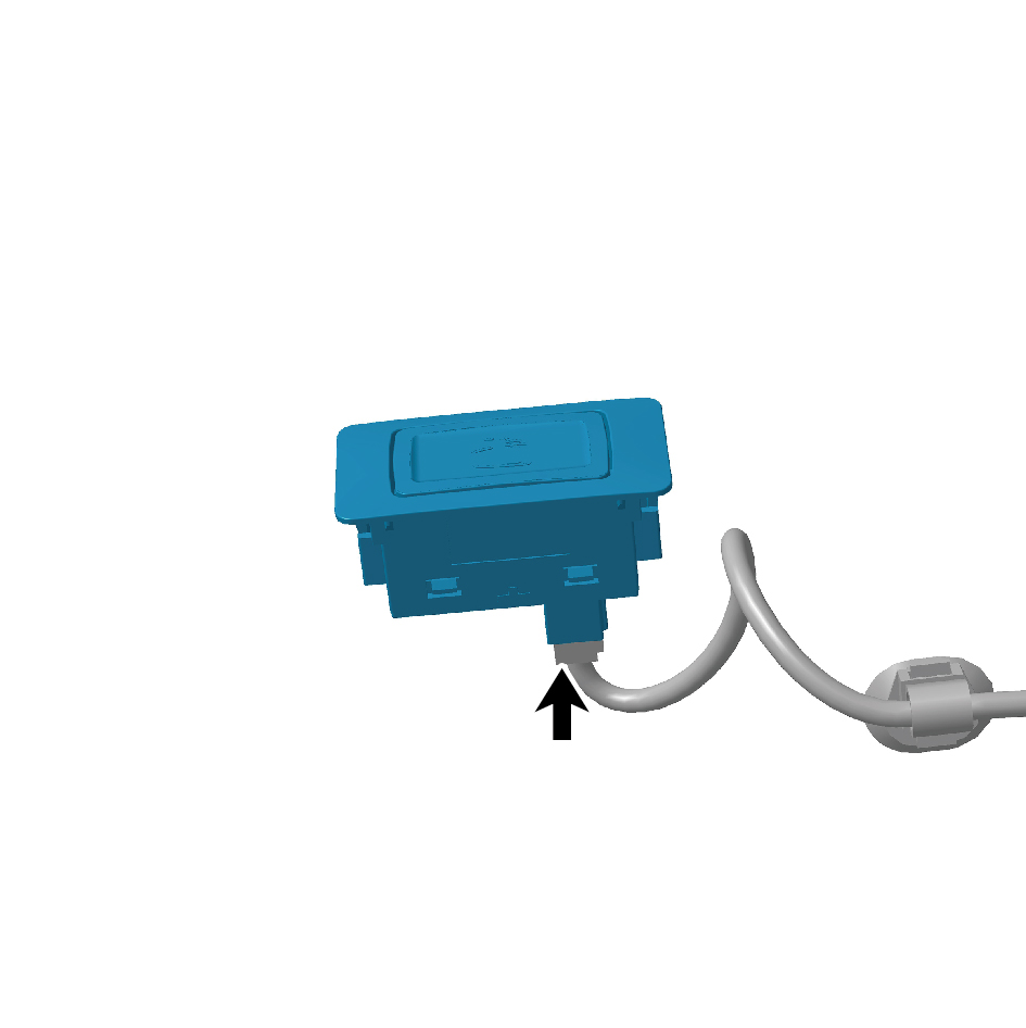
switch.
6
Remove the electric sliding door switch.
Installation Procedures
1
Move the electric sliding door switch to the mounting
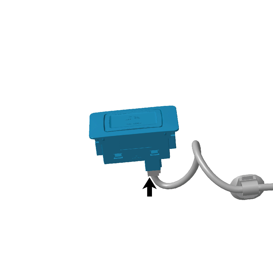
position.
2
Connect1 harness connector of the electric sliding door
switch.
caution
The harness is firmly connected following the
principal of "insert until a click is heard for
confirmation".
3
Install the electric sliding door switch.
4
Connect the battery negative cable.
5
Close the front flip cover plate.
6
Close the door.
7.7.4.5 Replacement of Combination Switch
Removal Procedures
1
Open the door.
2
Open the front flip cover plate.
3
Disconnect the battery negative cable.
caution
power down the high-voltage system before
disconnecting the negative pole of the storage
battery.
4
Remove the combination switch upper shield assembly.
5
Remove the combination switch lower shield.
6
Remove the driver horn cover assembly.
7
Remove the steering wheel assembly.
8
Remove the clock spring.
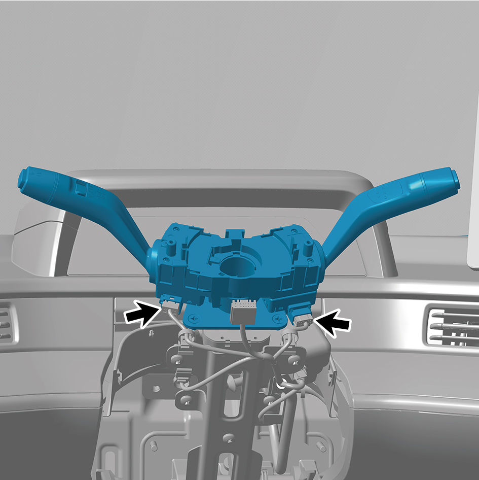
9
Disconnect 2 harness connectors of the combination
switch.
10
Detach the combination switch clip.
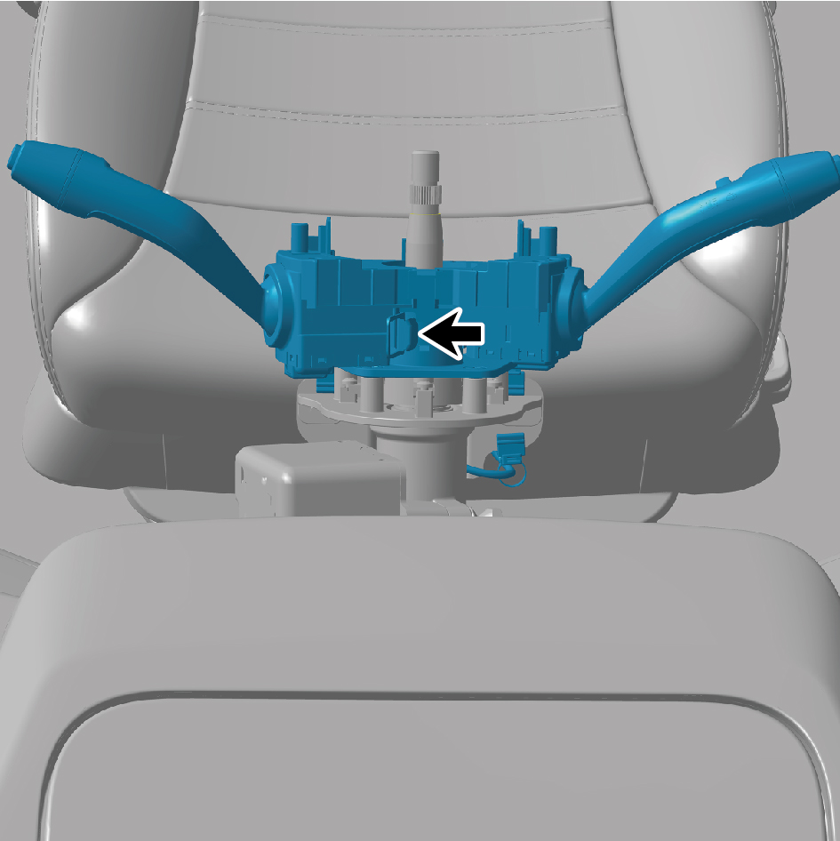
11
Remove the combination switch.
Installation Procedures
10
Move the combination switch to the mounting position.
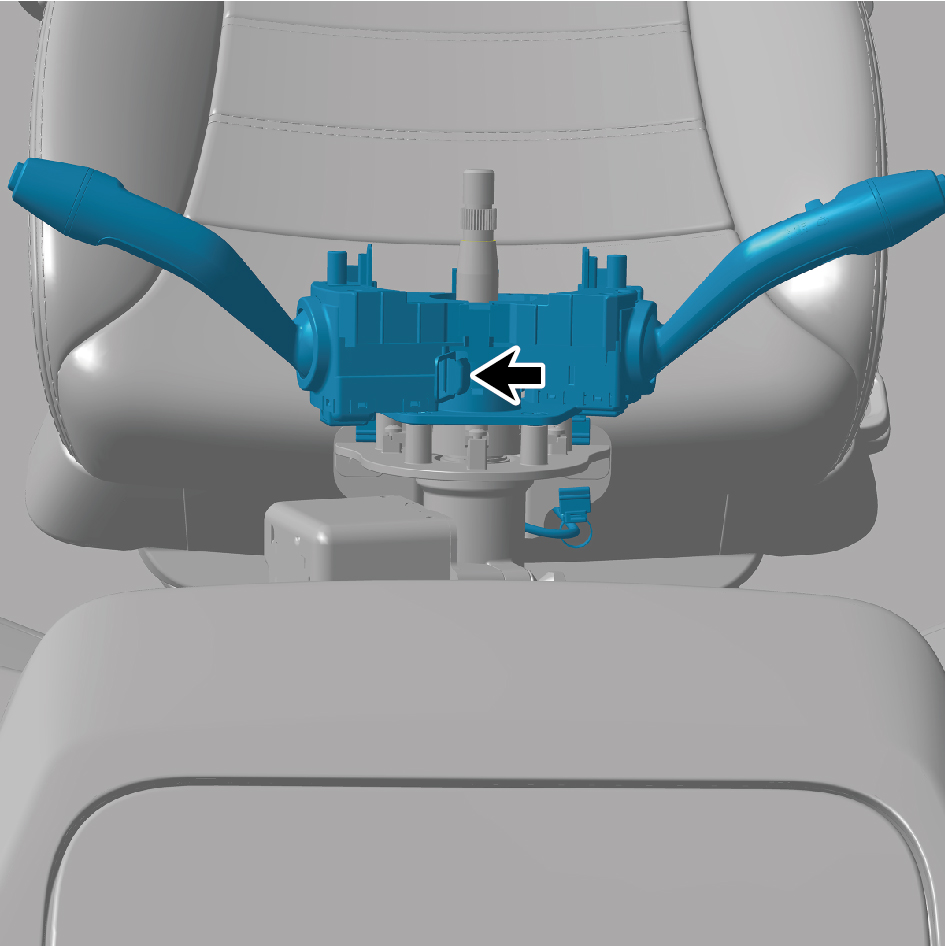
11
Connect the combination switch clip.
3
Connect 2 harness connectors of the combination switch.
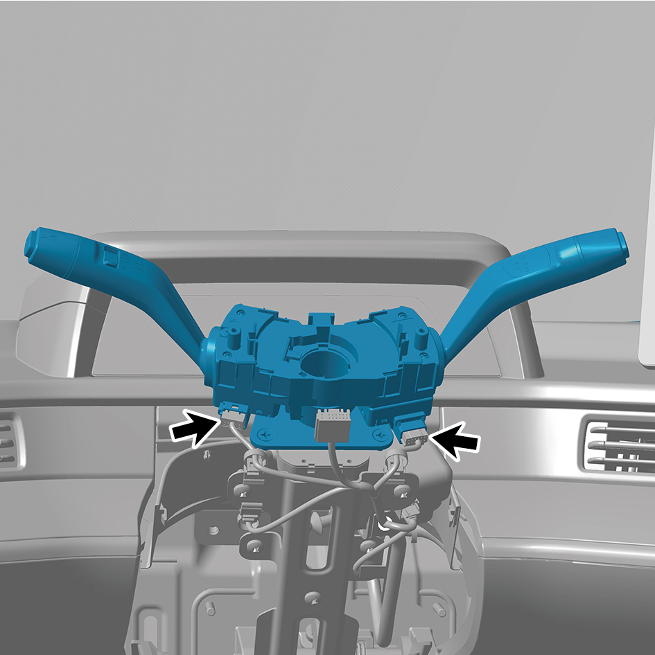
caution
The harness is firmly connected following the
principal of "insert until a click is heard for
confirmation".
4
Install the clock spring.
5
Install the steering wheel assembly.
6
Install the driver horn cover assembly.
7
Install the combination switch lower shield.
8
Install the combination switch upper shield assembly.
9
Connect the battery negative cable.
10
Close the front flip cover plate.
11
Close the door.
7.7.4.6 Replacement of Clock Spring
Removal Procedures
1
Open the door.
2
Open the front flip cover plate.
3
Disconnect the battery negative cable.
caution
power down the high-voltage system before
disconnecting the negative pole of the storage
battery.
4
Remove the combination switch upper shield assembly.
5
Remove the combination switch lower shield.
6
Remove the driver horn cover assembly.
7
Remove the steering wheel assembly.
8
Disconnect 1 harness connector of the clock spring.
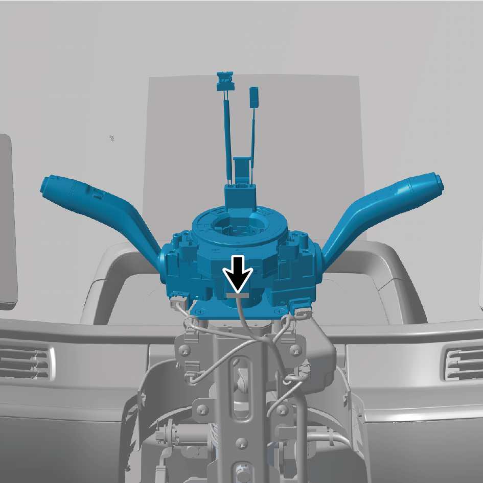
9
Remove the clock spring.
Installation Procedures
1
Move the clock spring to the mounting position.
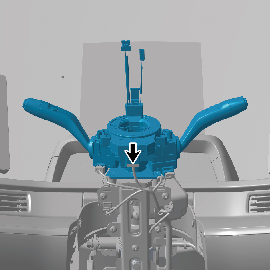
2
Install 1 harness connector of the clock spring.
caution
The harness is firmly connected following the
principal of "insert until a click is heard for
confirmation".
3
Install the steering wheel assembly.
4
Install the driver horn cover assembly.
5
Install the combination switch lower shield.
6
Install the combination switch upper shield assembly.
7
Connect the battery negative cable.
8
Close the front flip cover plate.
9
Close the door.
7.7.4.7 Replacement of Storage Compartment Lamp Switch
Lamp Switch
Removal Procedures
1
Open the door.
2
Open the front flip cover plate.
3
Disconnect the battery negative cable.
caution
power down the high-voltage system before
disconnecting the negative pole of the storage
battery.
4
Remove 1 fixing screw of the storage compartment lamp
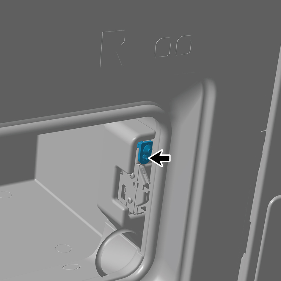
switch.
5
Disconnect 1 harness connector of the storage
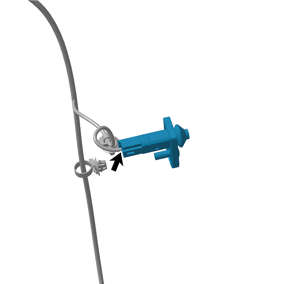
compartment lamp switch.
6
Remove the storage compartment lamp switch.
Installation Procedures
1
Move the storage compartment lamp switch to the
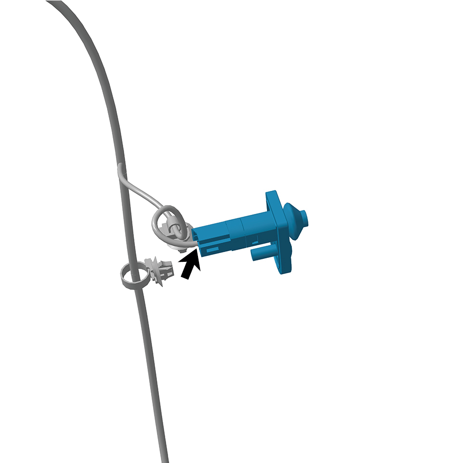
mounting position.
2
Connect 1 harness connector of the storage compartment
lamp switch.
caution
The harness is firmly connected following the
principal of "insert until a click is heard for
confirmation".
3
Install 1 fixing screw of the storage compartment lamp
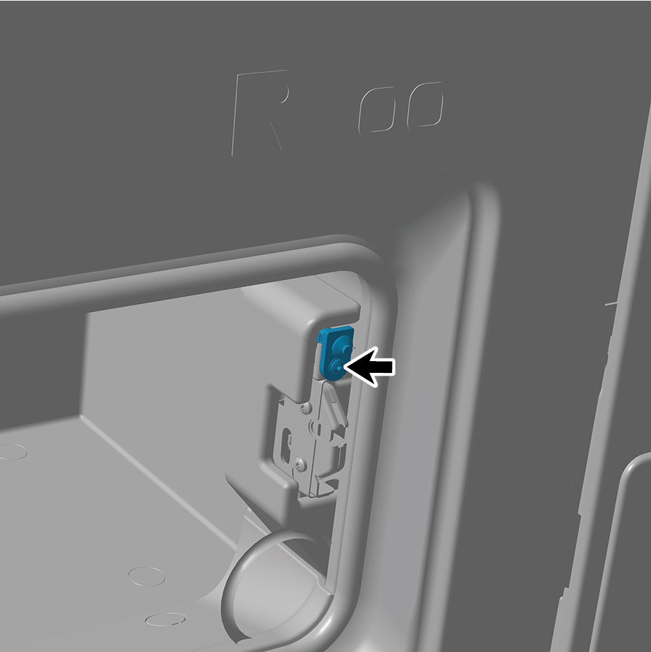
switch.
4
Connect the battery negative cable.
5
Close the front flip cover plate.
6
Close the door.