← Back to Contents
7 Automotive Electrical Appliances / 7.6 Vehicle-mounted Power Supply Device | PDF pages 1505-1513
7.6 Vehicle-mounted Power Supply Device
7.6 Vehicle-mounted Power Supply Device
7.6 Vehicle-mounted Power Supply
Device
7.6.1 Specifications
7.6.1.1 Fastener Specifications
Range Of Torque
Fastener Specifications
Specifications
Foot Pounds of Torque (ft lbs)
The fixing bolt connecting the 120V
power supply body to the rear enclosure
(6.5 +/- 2) ft lbs
M5
panel assembly
7.6.2 Dismantling and Installation
7.6.2.1 Replacement of 120V Power
Removal Procedures
1
Open the door.
2
Open the front flip cover plate.
3
Disconnect the battery negative cable.
caution
power down the high-voltage system before
disconnecting the negative pole of the storage
battery.
4
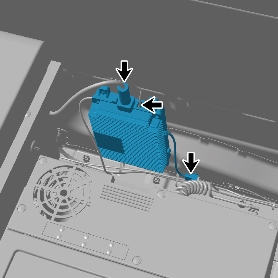
Disconnect 3 harness connectors of the 120V power.
5
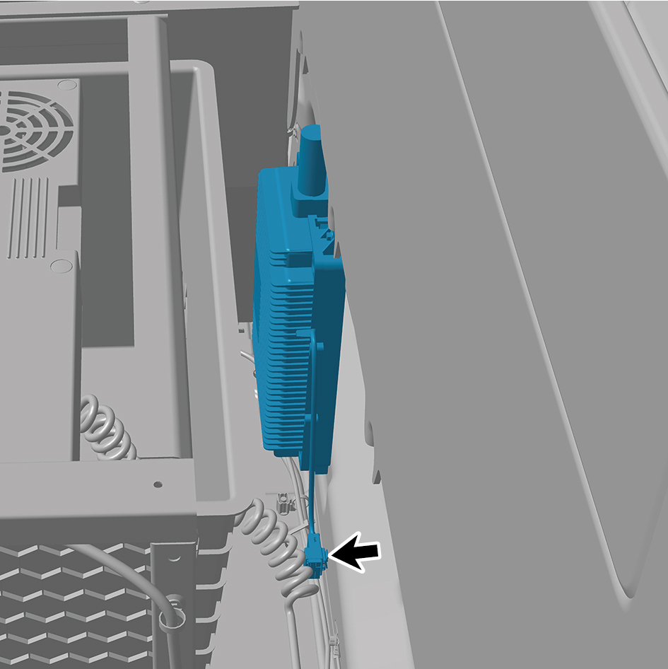
Disengage 1 fixing clip of the 120V power.
6
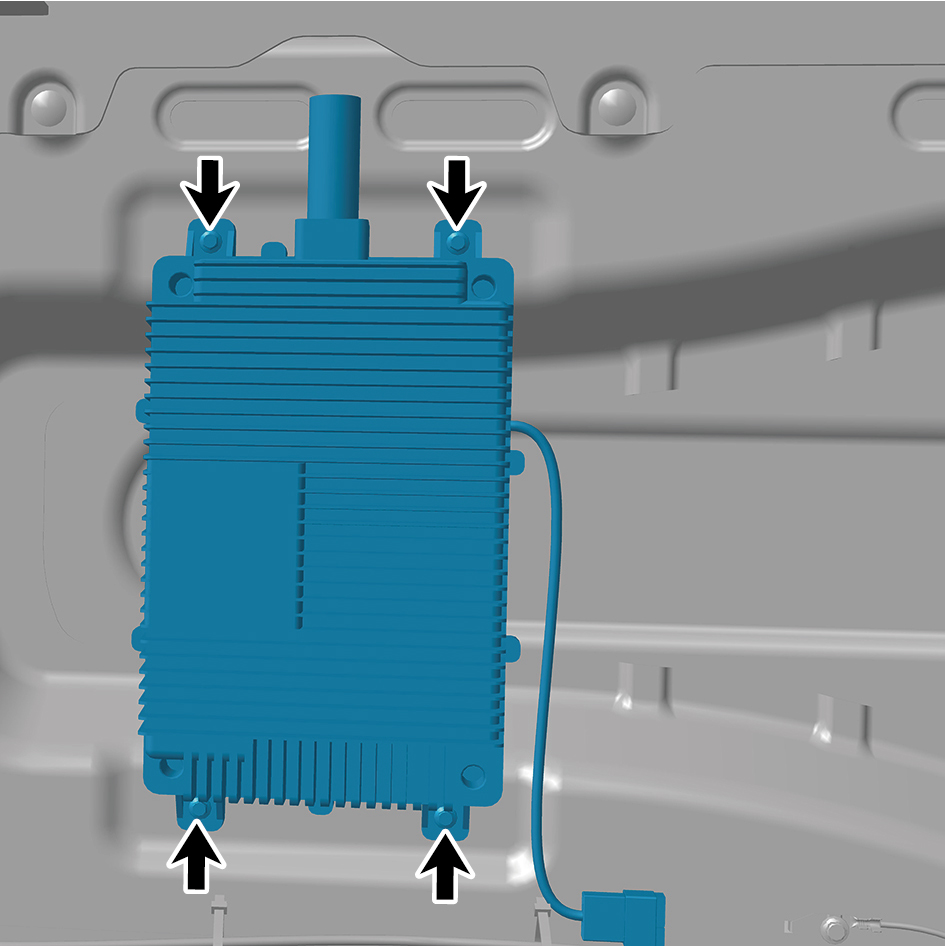
Remove 4 fixing bolts of the 120V power.
7
Remove the 120V power.
Installation Procedures
1
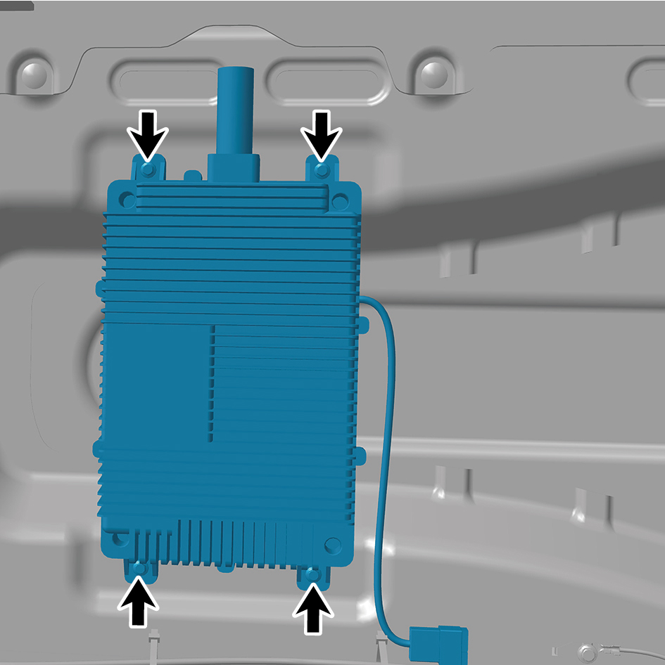
Move the 120V power to the mounting position.
2
Install 4 fixing bolts of the 120V power.
Torque: (6.5 +/- 2) ft lbs
3
Install 1 fixing clip of the 120V power.
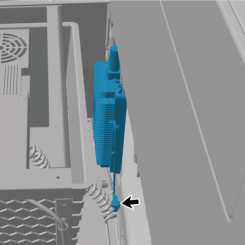
4
Connect 3 harness connectors of the 120V power.
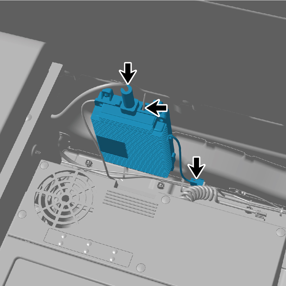
caution
The harness is firmly connected following the
principal of "insert until a click is heard for
confirmation".
5
Connect the battery negative cable.
6
Close the front flip cover plate.
7
Close the door.
7.6.2.2 Replacement of Vehicle Power Supply (12V)
(12V)
Removal Procedures
1
Open the door.
2
Open the front flip cover plate.
3
Disconnect the battery negative cable.
caution
power down the high-voltage system before
disconnecting the negative pole of the storage
battery.
4
Disconnect 1 harness connector of the vehicle power
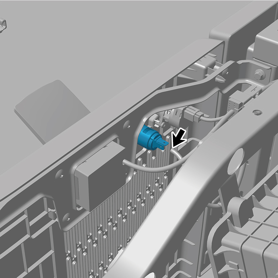
supply (12V).
5
Remove the vehicle power supply (12V).
Installation Procedures
1
Move the vehicle power supply (12V) to the mounting
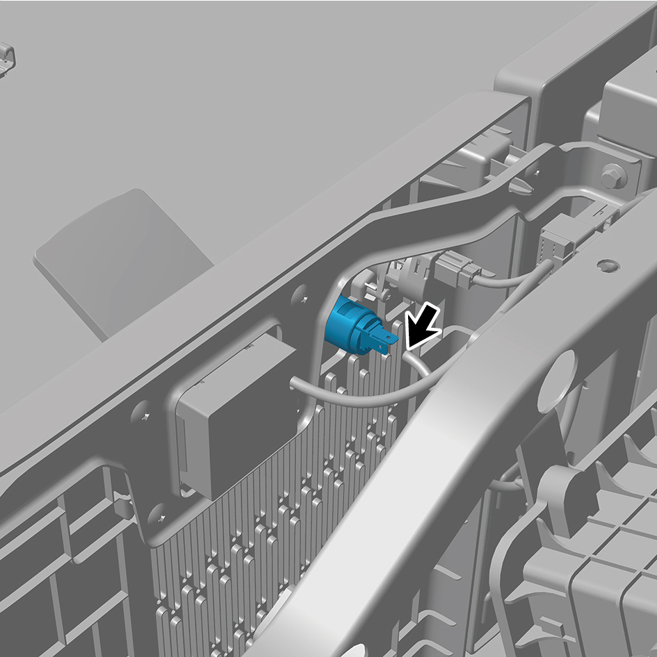
position.
2
Connect 1 harness connector of the vehicle power supply
(12V).
caution
The harness is firmly connected following the
principal of "insert until a click is heard for
confirmation".
3
Connect the battery negative cable.
4
Close the front flip cover plate.
5
Close the door.
7.6.2.3 Replacement of 120V Receptacle
Removal
Procedures
1
Open the door.
2
Open the front flip cover plate.
3
Disconnect the battery negative cable.
caution
power down the high-voltage system before
disconnecting the negative pole of the storage
battery.
4
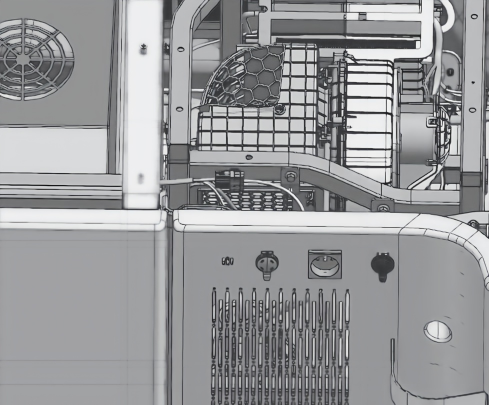
Disconnect 1 harness connector of the 230V receptacle.
5
Remove the 230V receptacle.
Installation
Procedures
1
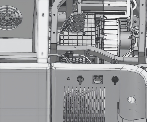
Move the 230V receptacle to the mounting position.
2
Connect 1 harness connector of the 230V receptacle.
caution
The harness is firmly connected following the
principal of "insert until a click is heard for
confirmation".
3
Connect the battery negative cable.
4
Close the front flip cover plate.
5
Close the door.
7.6.2.4 Replacement of Rear USB Interface
Removal Procedures
1
Open the door.
2
Open the front flip cover plate.
3
Disconnect the battery negative cable.
caution
power down the high-voltage system before
disconnecting the negative pole of the storage
battery.
4
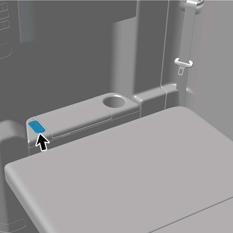
Detach the rear USB interface.
5
Disconnect 1 harness connector of the rear USB
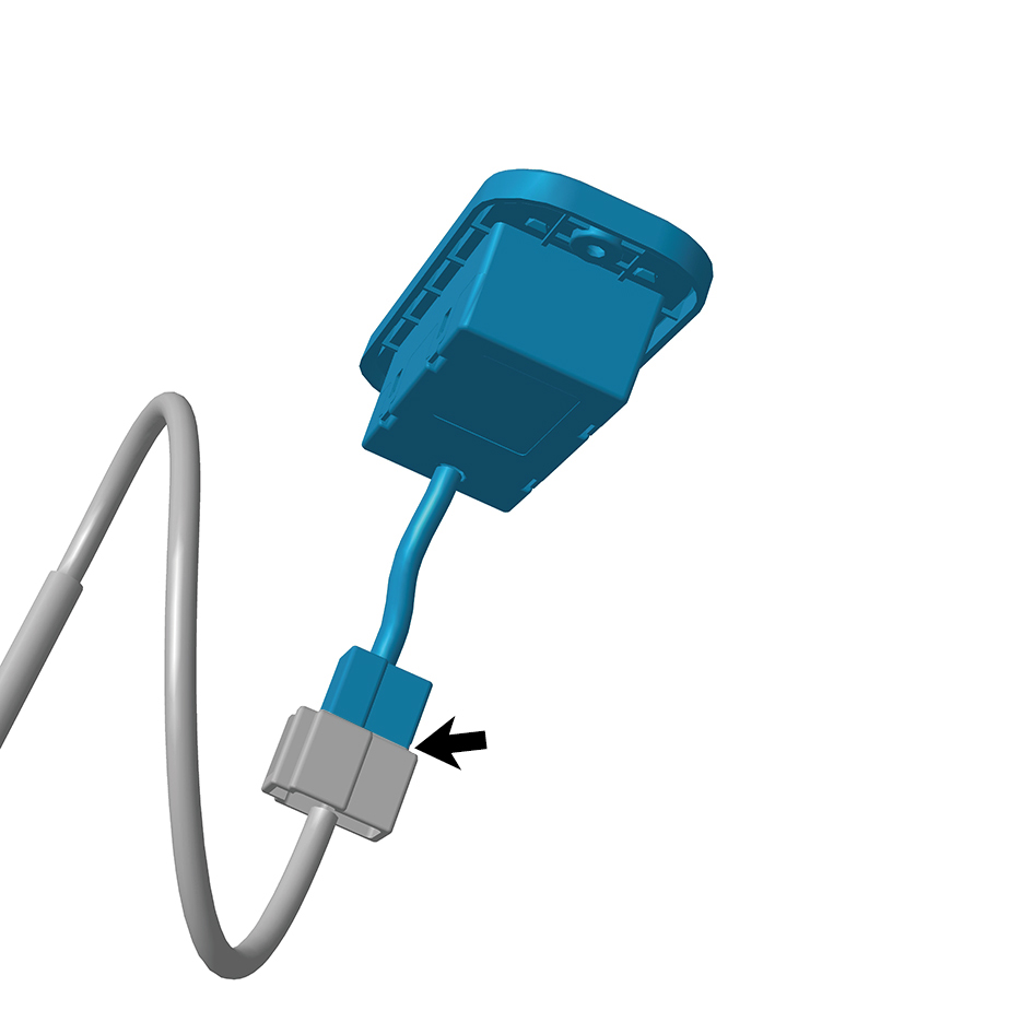
interface.
6
Remove the rear USB interface.
Installation Procedures
1
Move the rear USB interface to the mounting position.
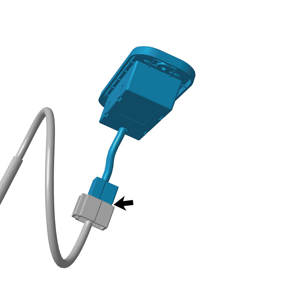
2
Connect 1 harness connector of the rear USB interface.
caution
The harness is firmly connected following the
principal of "insert until a click is heard for
confirmation".
3
Install the rear USB interface.
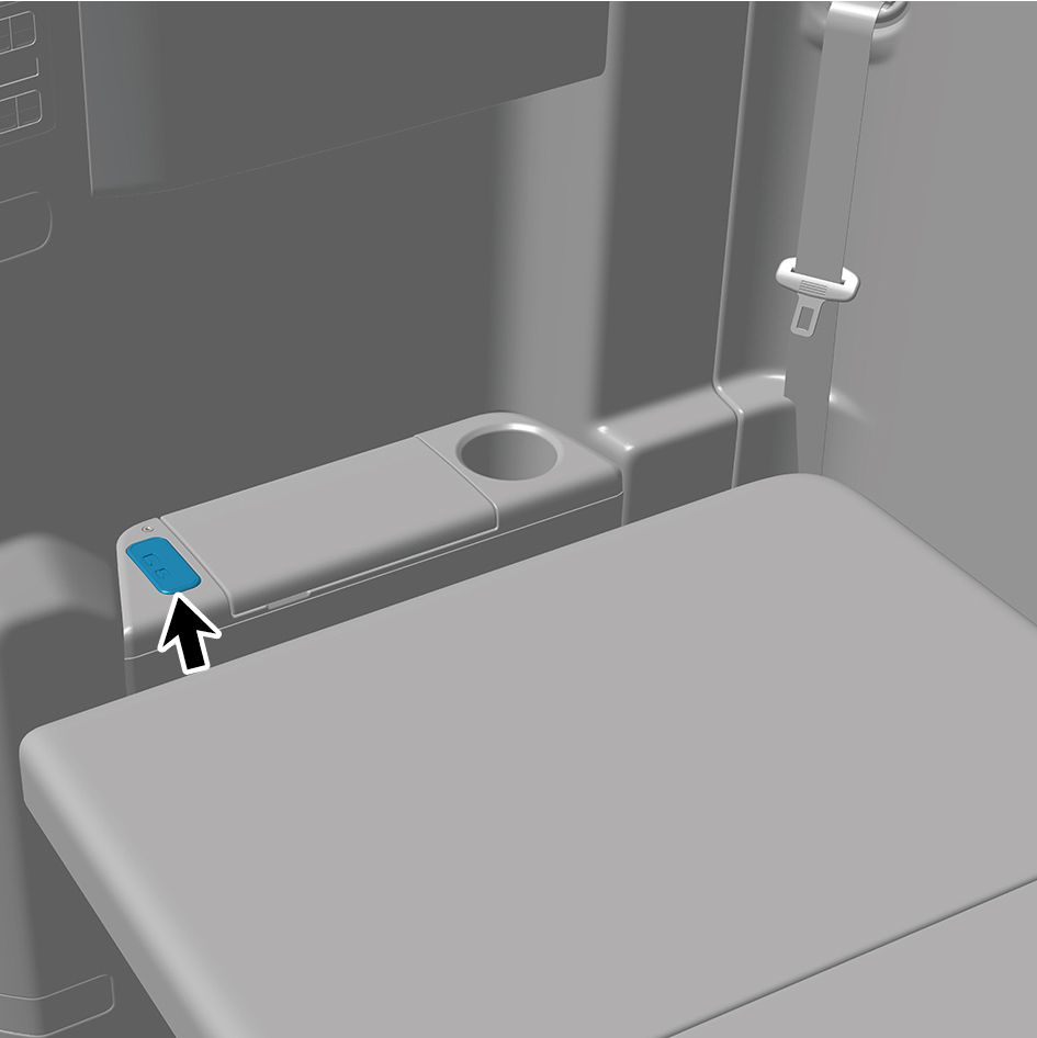
4
Connect the battery negative cable.
5
Close the front flip cover plate.
6
Close the door.
7.6.2.5 Replacement of Front USB Interface
Removal Procedures
1
Open the door.
2
Open the front flip cover plate.
3
Disconnect the battery negative cable.
caution
power down the high-voltage system before
disconnecting the negative pole of the storage
battery.
4
Disconnect 2 harness connectors of the front USB
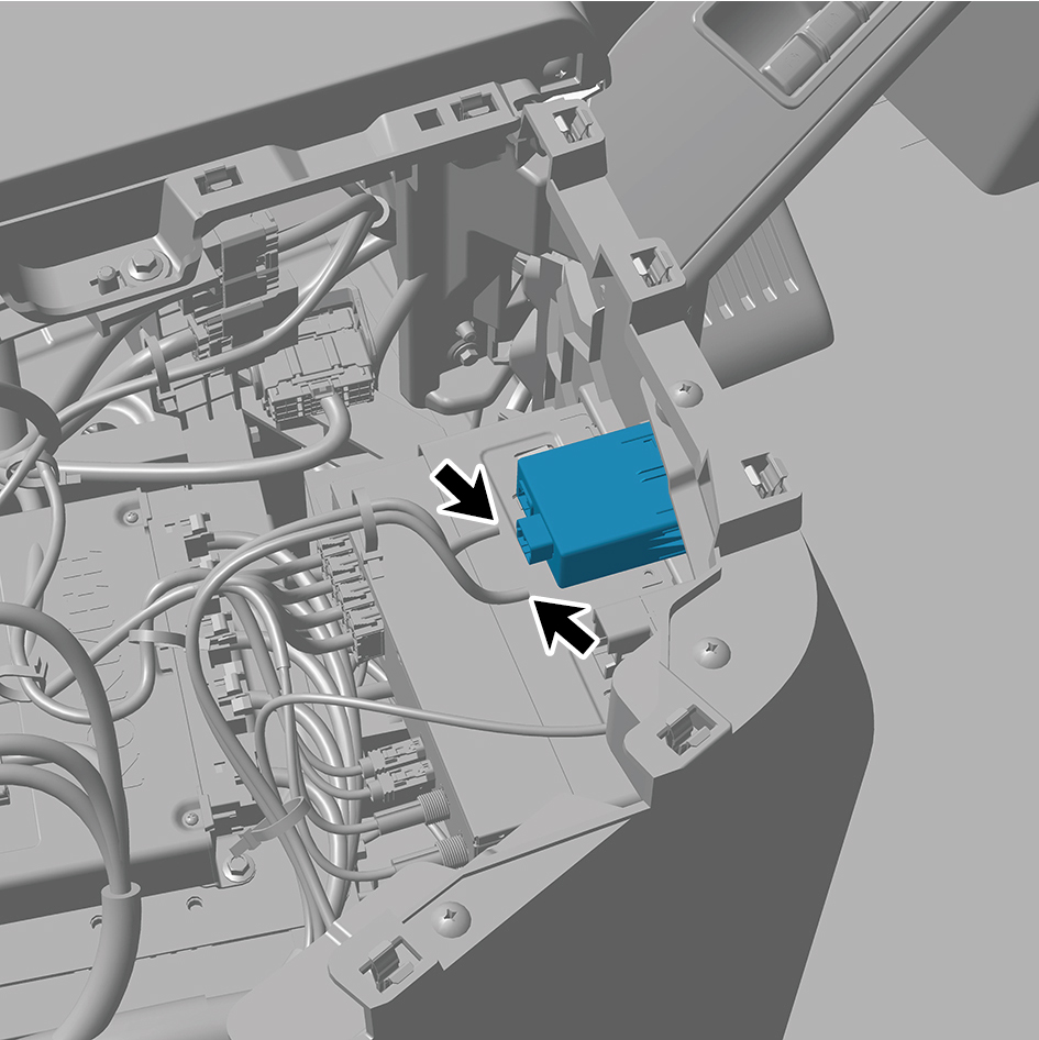
interface.
5
Remove the front USB interface.
Installation Procedures
1
Move the front USB interface to the mounting position.
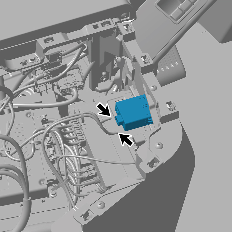
2
Connect 2 harness connectors of the front USB interface.
caution
The harness is firmly connected following the
principal of "insert until a click is heard for
confirmation".
3
Connect the battery negative cable.
4
Close the front flip cover plate.
5
Close the door.