← Back to Contents
7 Automotive Electrical Appliances / 7.4 Battery Device | PDF pages 1277-1492
7.4 Battery Device
7.4 Battery Device
7.4.1 Specifications
7.4.1.1 Fastener Specifications
Range Of Torque
Fastener Specifications
Specifications
Foot Pounds of Torque (ft lbs)
The fixing bolt connecting the battery
assembly bracket to the right front
(103 +/- 7.5) ft lbs
M14
connecting beam
The fixing bolt connecting the battery
assembly bracket to the left front
(103 +/- 7.5) ft lbs
M14
connecting beam
The fixing nut connecting the battery
assembly bracket to the right front
(103 +/- 7.5) ft lbs
M14
connecting beam
The fixing nut connecting the battery
assembly bracket to the right front
(103 +/- 7.5) ft lbs
M14
connecting beam
The fixing bolt connecting the battery
(18.5 +/- 2) ft lbs
M8
pad and the battery assembly bracket
Intelligent electrical box - fixing bolt
(6.5 +/- .75) ft lbs
M6
connecting the vehicle body to the lower
left dashboard controller bracket
Intelligent electrical box - fixing bolts
(18.5 +/- 2) ft lbs
M8
connecting the chassis and intelligent
electrical box bracket
The fixing nut connecting the auxiliary
battery and the negative terminal
(18.5 +/- 2) ft lbs
M8
harness of the battery
The fixing bolt connecting the battery
(6.5 +/- .75) ft lbs
M6
pressure plate 3 to the power domain
controller bracket
7.4.2 Decomposition Diagram
7.4.2.1 Decomposition Diagram
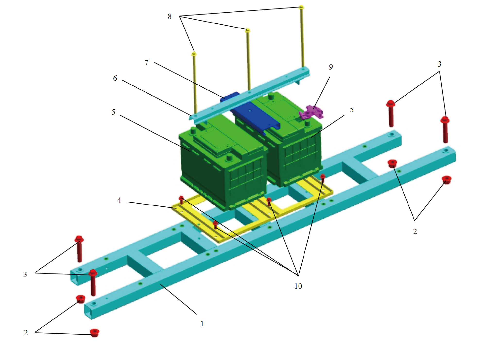
1.
Battery Bracket
6.
Battery Pressing Plate 3
7.
2.
Hexagon Flange Lock Nut_All Metal
Battery Pressing Plate 2
3.
Hexagon Flange Bolt
8.
Battery Tie Rod
4.
9.
Battery Tray
Smart Battery Sensor
5.
10.
Auxiliary Battery
Hexagon Flange Bolt
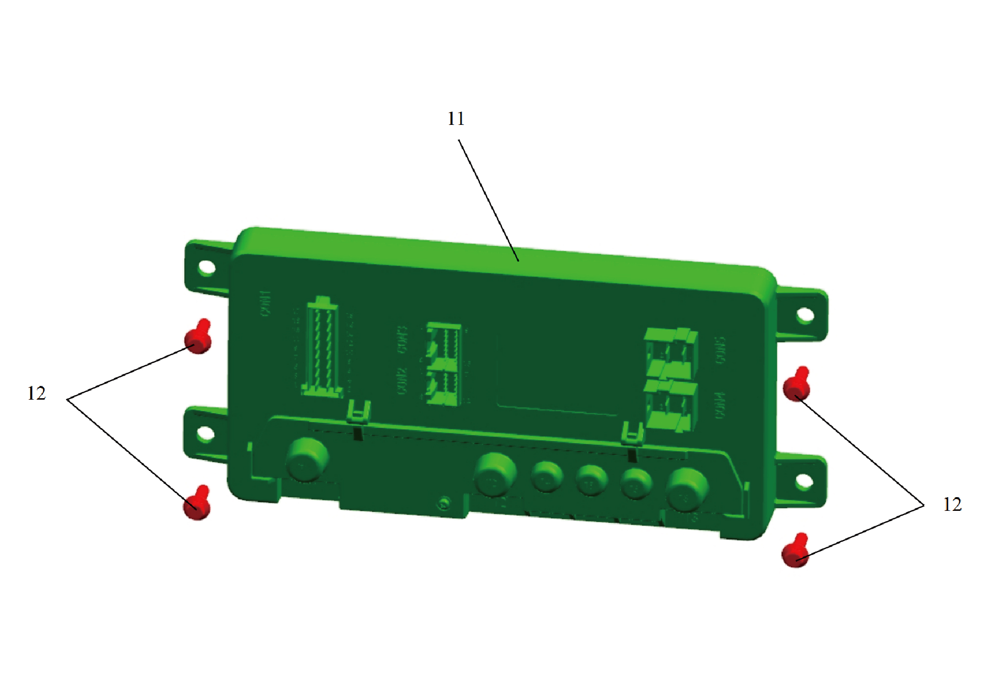
11.
12.
Hexagon Flange Bolt
Smart Junction Box-Body
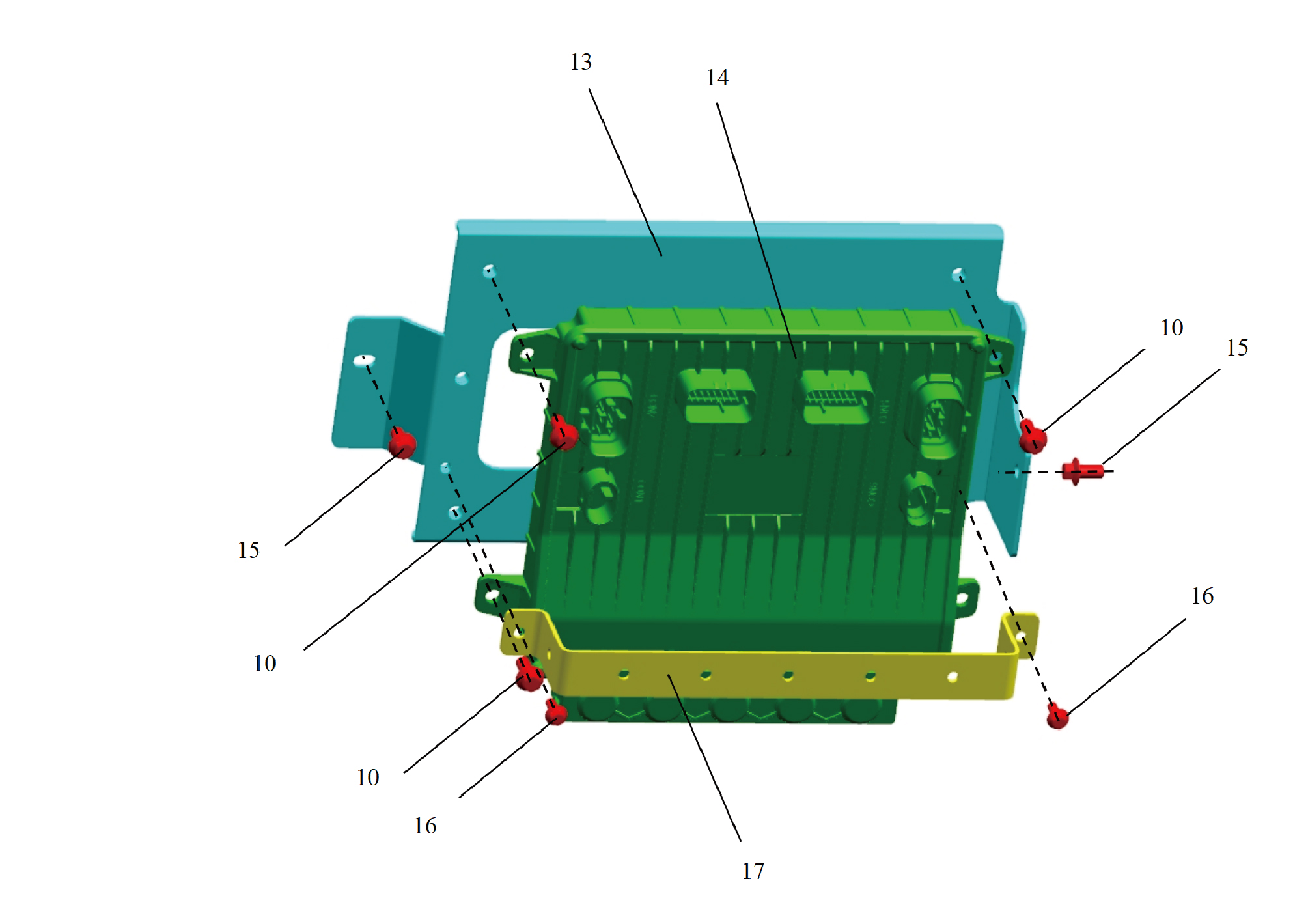
10
Hexagon Flange Bolt
15.
Hexagon Flange Bolt
13.
16.
Hexagon Flange Bolt
Smart Junction Box Bracket-Chassis
14.
17.
Smart Junction Box-Chassis
Smart Junction Box Bracket-Chassis 2
7.4.3 Dismantling and Installation
7.4.3.1 Replacement of Battery Assembly Bracket
Bracket
Removal Procedures
1
Open the door.
2
Open the front flip cover plate.
3
Disconnect the battery negative cable.
caution
It is necessary to power down the high-voltage
system before disconnecting the negative pole of the
storage battery.
4
Remove the VDC assembly.
5
Remove the VDC bracket.
6
Remove the battery rod.
7
Remove the battery pressure plate 3.
8
Remove the battery pressure plate 2.
9
Remove the auxiliary battery.
10
Remove the battery backing plate.
11
Remove Left Junction Box.
12
Remove Right Junction Box.
13
Remove 4 fixing bolts of the battery assembly bracket.
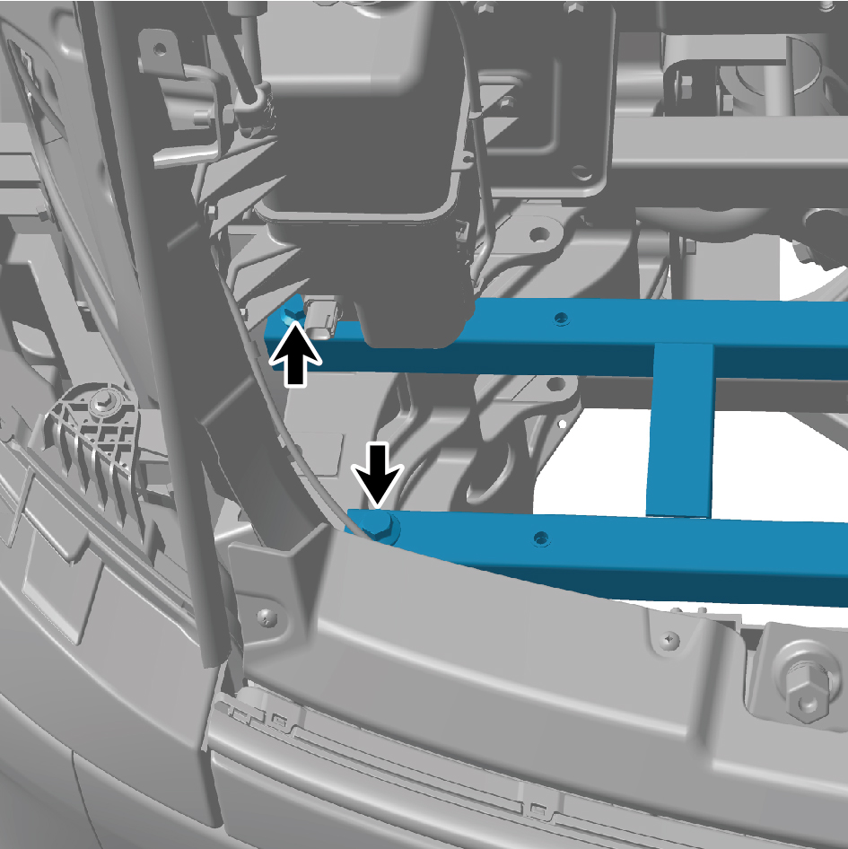
14
Remove the battery assembly bracket.
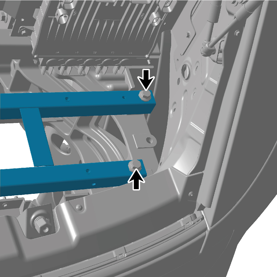
Installation Procedures
1
Move the battery assembly bracket to the mounting
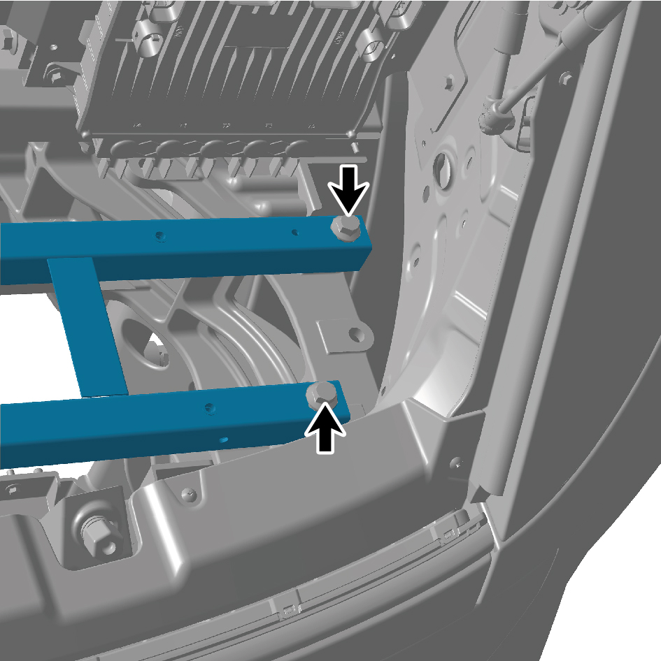
position.
2
Install 4 fixing bolts of the battery assembly bracket.
Torque: (103 +/- 7.5) ft lbs
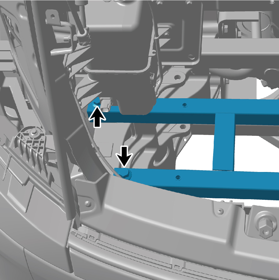
3
Install Right Junction Box.
4
Install Left Junction Box.
5
Install the battery backing plate.
6
Install the auxiliary battery.
7
Install the battery pressure plate 2.
8
Install the battery pressure plate 3.
9
Install the battery rod.
10
Install the VDC bracket.
11
Install the VDC assembly.
12
Connect the battery negative cable.
13
Close the front flip cover plate.
14
Close the door.
7.4.3.2 Replacement of Battery Backing Plate
Removal Procedures
1
Open the door.
2
Open the front flip cover plate.
3
Disconnect the battery negative cable.
caution
power down the high-voltage system before
disconnecting the negative pole of the storage
battery.
4
Remove the VDC assembly.
5
Remove the VDC bracket.
6
Remove the battery rod.
7
Remove the battery pressure plate 3.
8
Remove the battery pressure plate 2.
9
Remove the auxiliary battery.
10
Remove 6 fixing bolts of the battery backing plate.
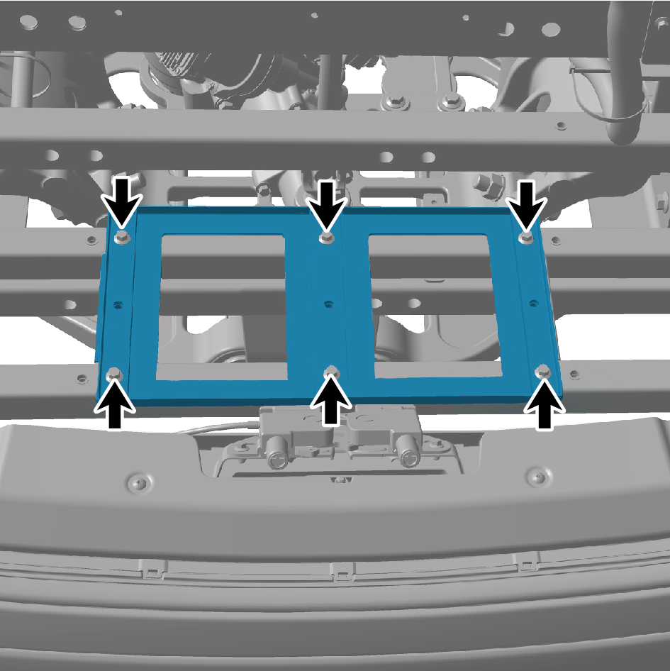
11
Remove the battery backing plate.
Installation Procedures
1
Move the battery backing plate to the mounting position.
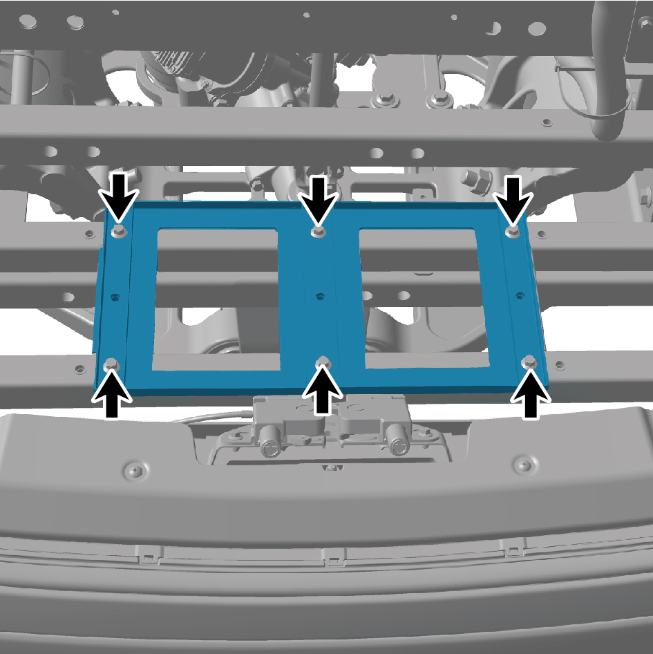
2
Install 6 fixing bolts of the battery backing plate.
Torque: (18.5 +/- 2) ft lbs
3
Install the auxiliary battery.
4
Install the battery pressure plate 2.
5
Install the battery pressure plate 3.
6
Install the battery rod.
7
Install the VDC bracket.
8
Install the VDC assembly.
9
Connect the battery negative cable.
10
Close the front flip cover plate.
11
Close the door.
7.4.3.3 Replacement of Auxiliary Battery
Removal Procedures
1
Open the door.
2
Open the front flip cover plate.
3
Disconnect the battery negative cable.
caution
power down the high-voltage system before
disconnecting the negative pole of the storage
battery.
4
Remove the VDC assembly.
5
Remove the VDC bracket.
6
Remove the battery rod.
7
Remove the battery pressure plate 3.
8
Remove the battery pressure plate 2.
9
Loosen 3 fixing nuts of the auxiliary battery terminal.
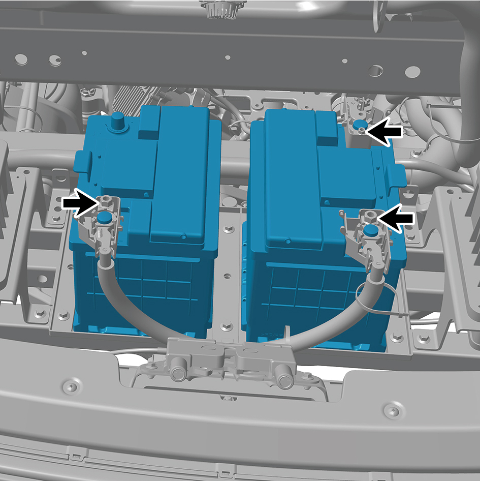
10
Remove the auxiliary battery.
Installation Procedures
1
Move the auxiliary battery rod to the mounting position.
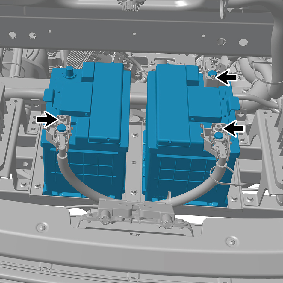
2
Tighten 3 fixing nuts of the auxiliary battery terminal.
Torque: (18.5 +/- 2) ft lbs
3
Install the battery pressure plate 2.
4
Install the battery pressure plate 3.
5
Install the battery rod.
6
Install the VDC bracket.
7
Install the VDC assembly.
8
Connect the battery negative cable.
9
Close the front flip cover plate.
10
Close the door.
7.4.3.4 Replacement of Battery Pressure Plate 2
2
Removal Procedures
1
Open the door.
2
Open the front flip cover plate.
3
Disconnect the battery negative cable.
caution
power down the high-voltage system before
disconnecting the negative pole of the storage
battery.
4
Remove the VDC assembly.
5
Remove the VDC bracket.
6
Remove the battery rod.
7
Remove the battery pressure plate 3.
8
Remove the battery pressure plate 2.
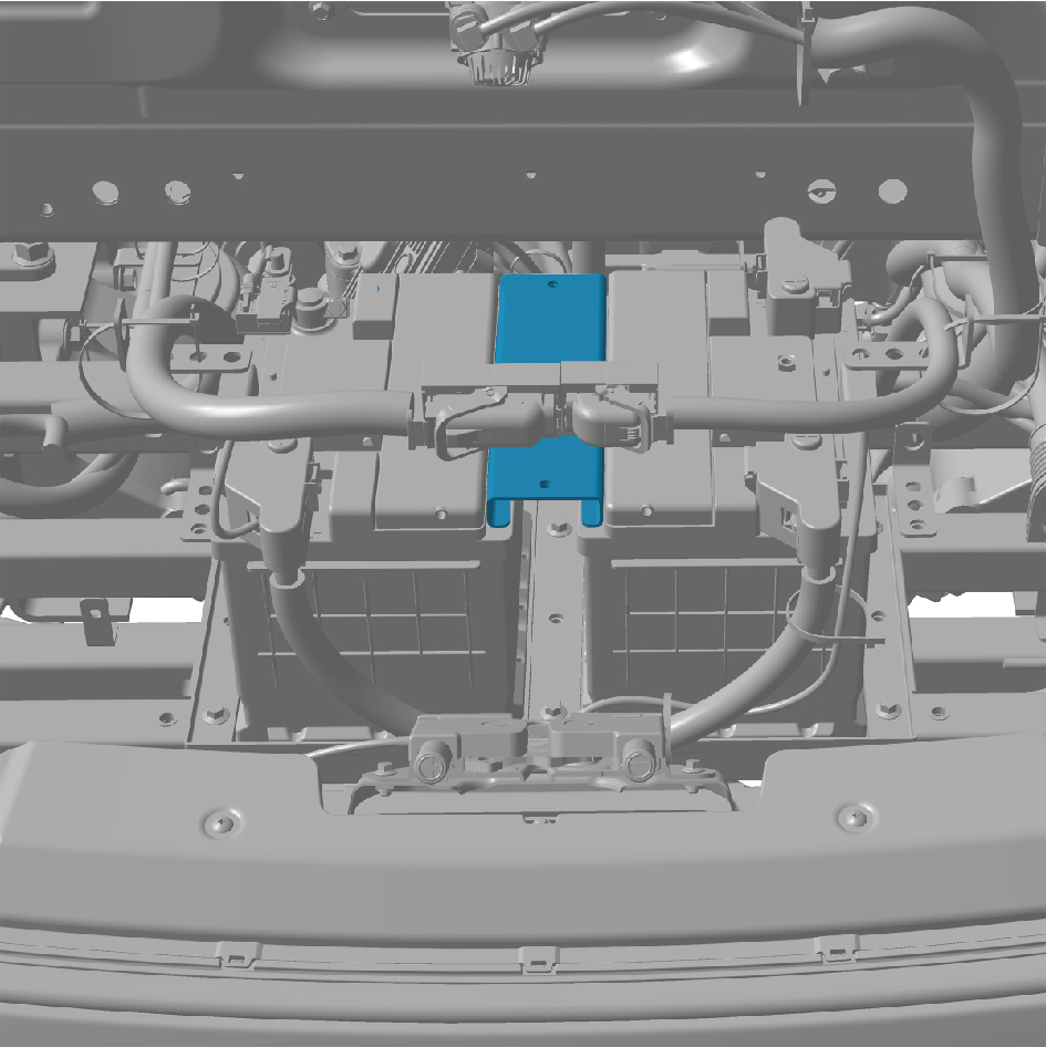
Installation Procedures
1
Move the battery pressure plate 2 to the mounting
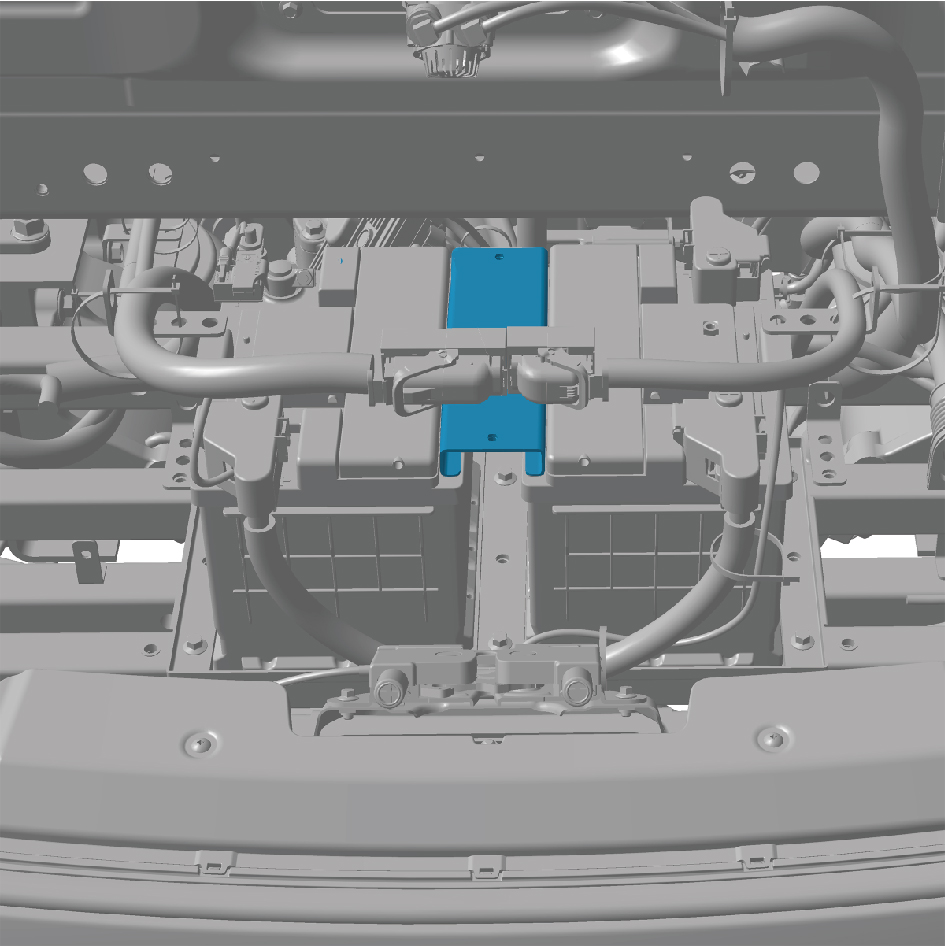
position.
2
Install the battery pressure plate 3.
3
Install the battery rod.
4
Install the VDC bracket.
5
Install the VDC assembly.
6
Connect the battery negative cable.
7
Close the front flip cover plate.
8
Close the door.
7.4.3.5 Replacement of Battery Pressure Plate 3
3
Removal Procedures
1
Open the door.
2
Open the front flip cover plate.
3
Disconnect the battery negative cable.
caution
power down the high-voltage system before
disconnecting the negative pole of the storage
battery.
4
Remove the VDC assembly.
5
Remove the VDC bracket.
6
Remove the battery rod.
7
Remove the battery pressure plate 3.
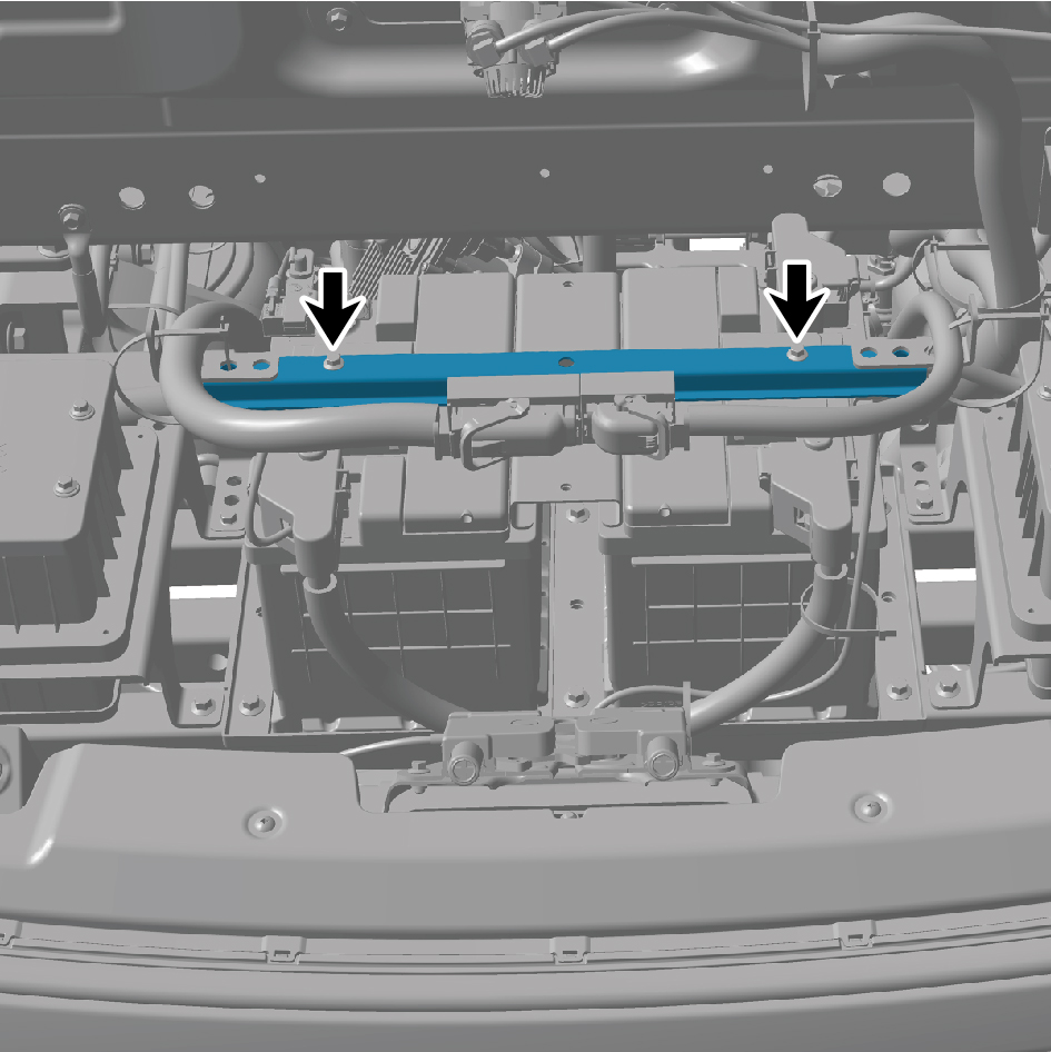
Installation Procedures
1
Move the battery pressure plate 3 to the mounting
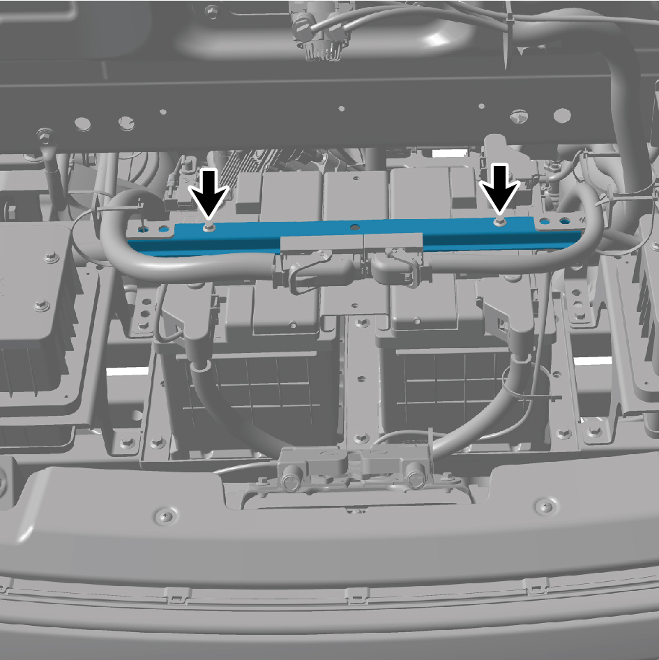
position.
2
Install the battery rod.
3
Install the VDC bracket.
4
Install the VDC assembly.
5
Connect the battery negative cable.
6
Close the front flip cover plate.
7
Close the door.
7.4.3.6 Replacement of Battery Rod
Removal Procedures
1
Open the door.
2
Open the front flip cover plate.
3
Disconnect the battery negative cable.
caution
power down the high-voltage system before
disconnecting the negative pole of the storage
battery.
4
Remove the VDC assembly.
5
Remove the vehicle controller assy bracket.
6
Remove 3 battery rods.
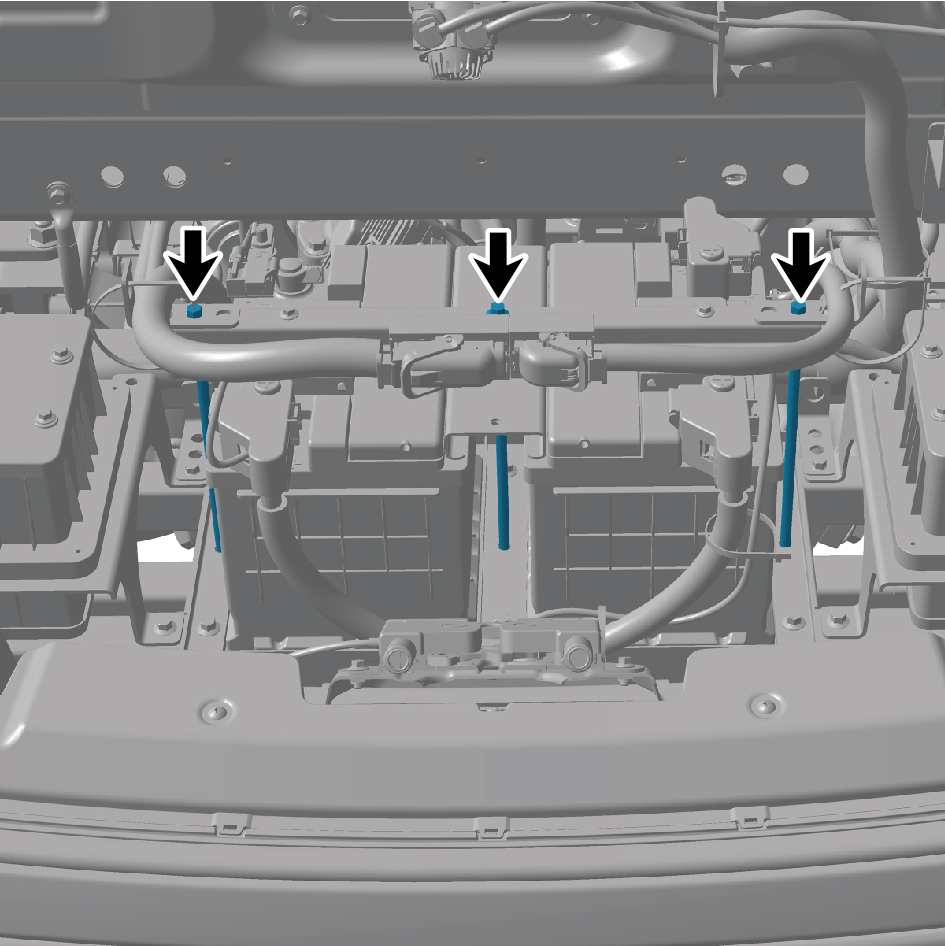
Installation Procedures
1
Move the battery rod to the mounting position.
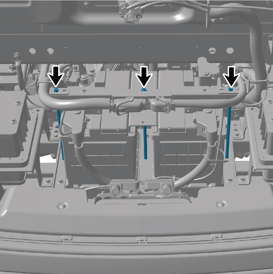
2
Install 3 battery rods.
3
Install the vehicle controller assy bracket.
4
Install the VDC assembly.
5
Connect the battery negative cable.
6
Close the front flip cover plate.
7
Close the door.
7.4.3.7 Replacement of IBS
Removal Procedures
1
Open the door.
2
Open the front flip cover plate.
3
Disconnect the battery negative cable.
caution
power down the high-voltage system before
disconnecting the negative pole of the storage
battery.
4
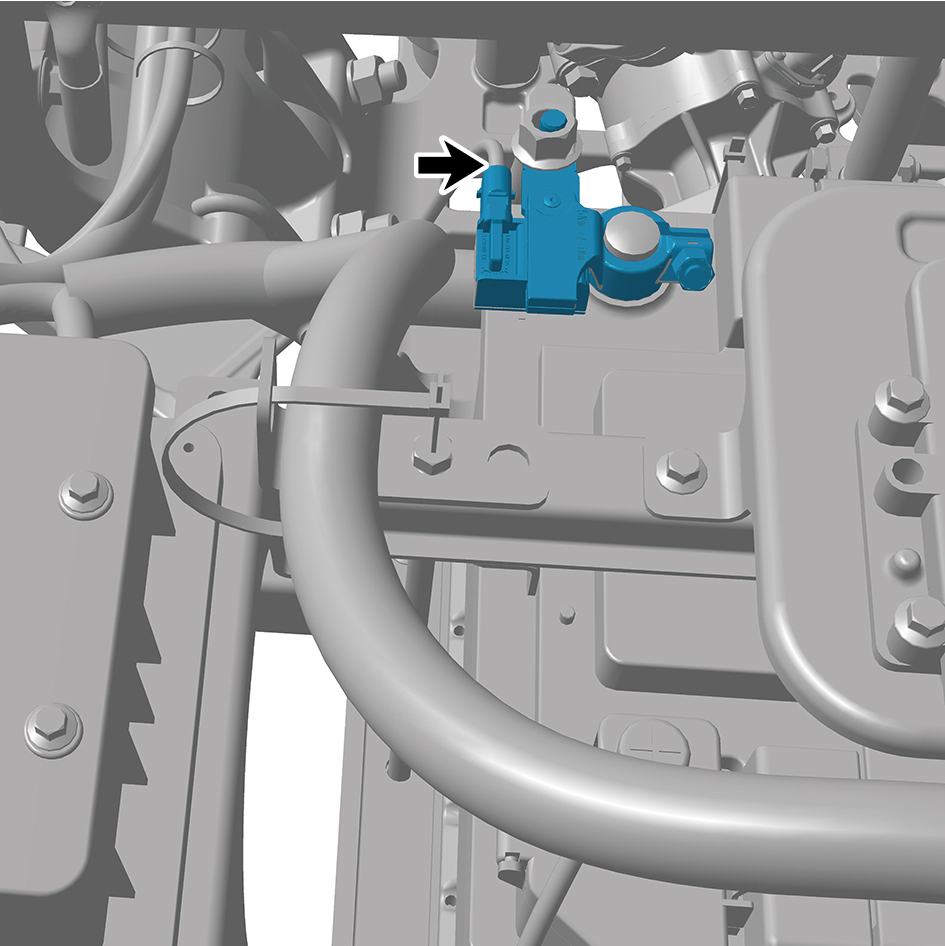
Disconnect 1 harness connector of the IBS.
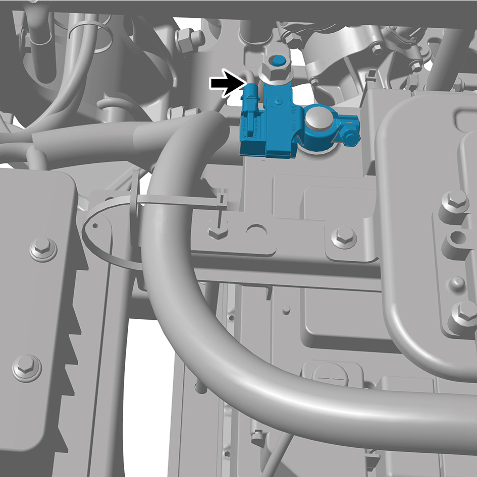
5
Remove 2 fixing nuts of the IBS.
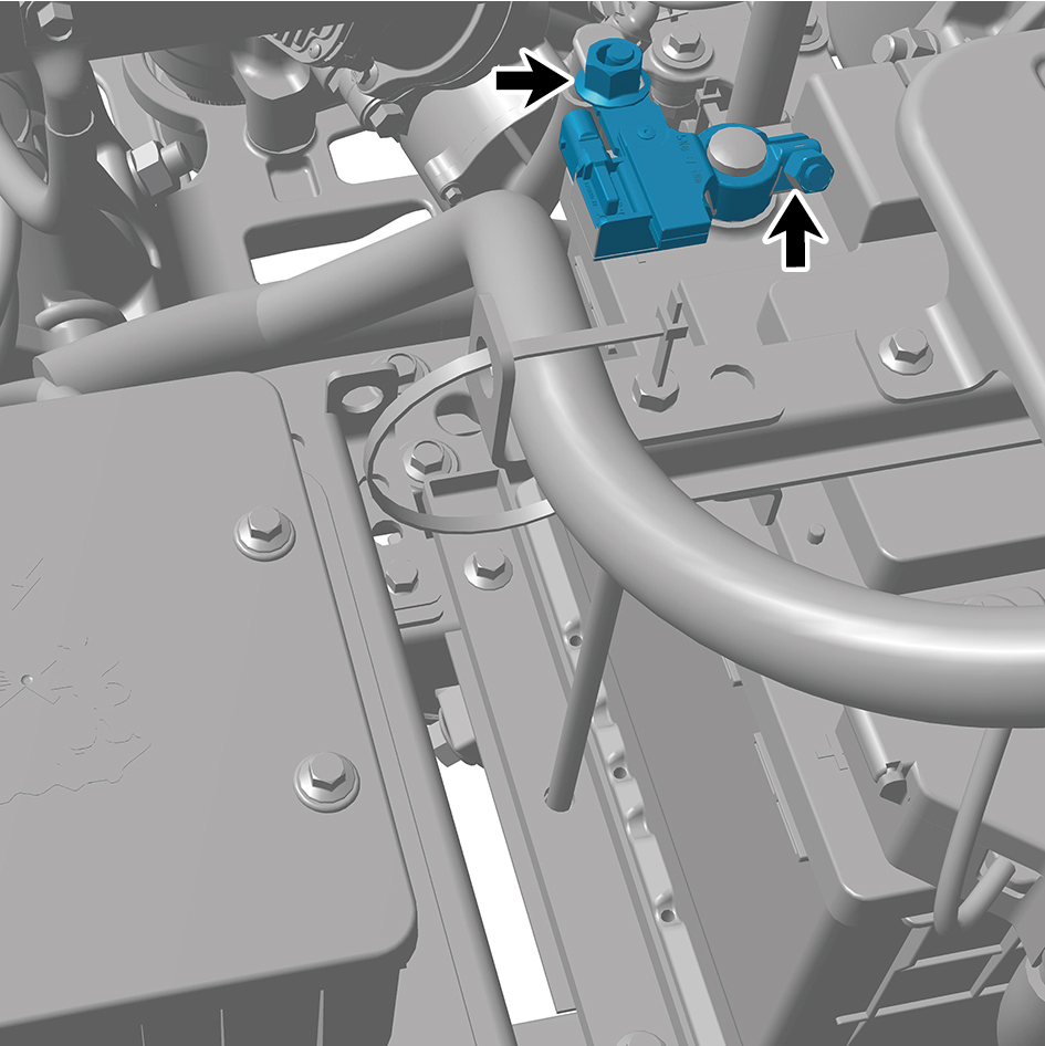
6
Remove the IBS.
Installation Procedures
1
Move the IBS to the mounting position.
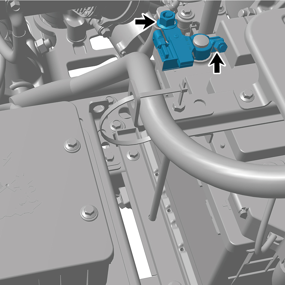
2
Install 2 fixing nuts of the IBS.
Torque: (14.75) ft lbs
3
Connect 1 harness connector of the IBS.
caution
The harness is firmly connected following the
principal of "insert until a click is heard for
confirmation".
4
Connect the battery negative cable.
5
Close the front flip cover plate.
6
Close the door.
7.4.3.8 Replacement of SJB_UP
Removal Procedures
1
Open the door.
2
Open the front flip cover plate.
3
Disconnect the battery negative cable.
caution
power down the high-voltage system before
disconnecting the negative pole of the storage
battery.
4
Remove the IP left upper trim panel assembly.
5
Remove the front USB interface.
6
Remove the vehicle controller assy bracket.
7
Remove the vehicle travelling data recorder bracket.
8
Remove the IP left access cover plate assembly.
9
Remove the left switch panel assembly.
10
Remove the left switch panel lower trim panel assembly.
11
Remove the IP left lower trim panel assembly.
12
Remove the left lower fixing bracket.
13
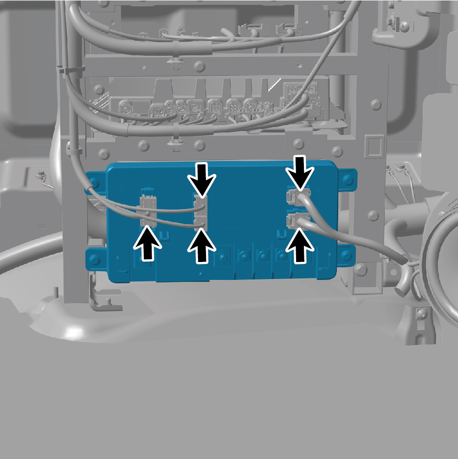
Disconnect 5 harness connectors of the SJB_UP.
14
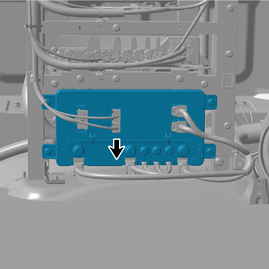
Remove 1 screw, and remove the SJB_UP cover plate.
15
Remove 3 fixing nuts of the harness to detach the
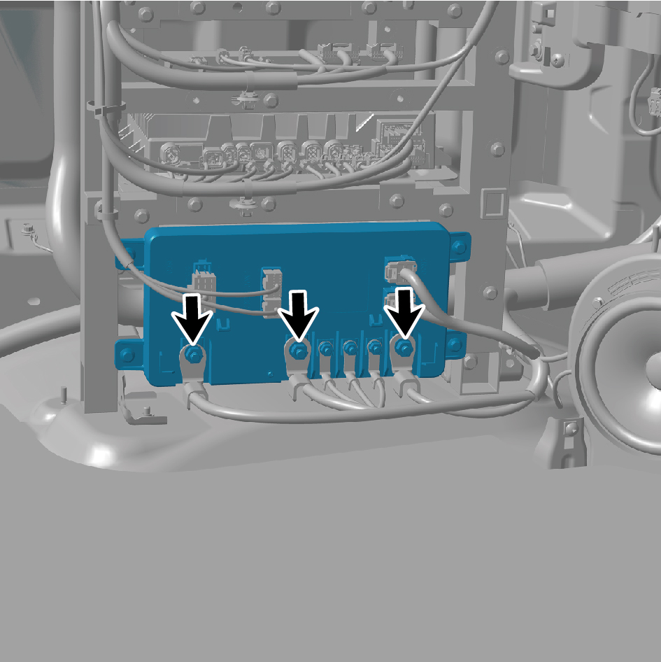
harness.
16
Remove 3 fixing nuts of the harness to detach the
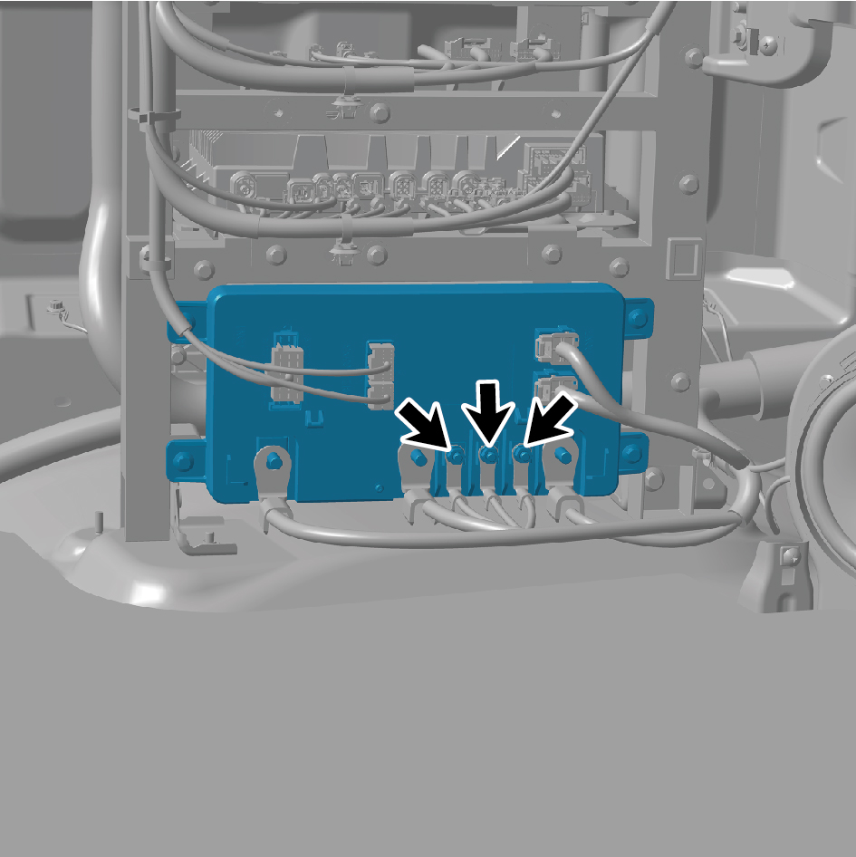
harness.
17
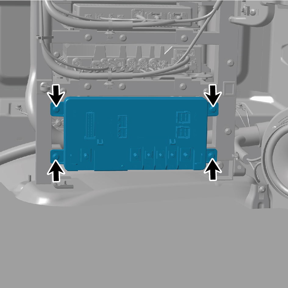
Remove 4 fixing bolts of the SJB_UP.
18
Remove the SJB_UP.
Installation Procedures
1
Move the SJB_UP to the mounting position.
2
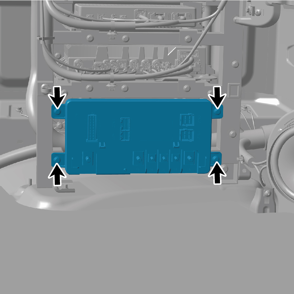
Install 4 fixing bolts of the SJB_UP.
Torque:(7.5 +/- .75) ft lbs
3
Connect the harness, and install 3 fixing nuts of the
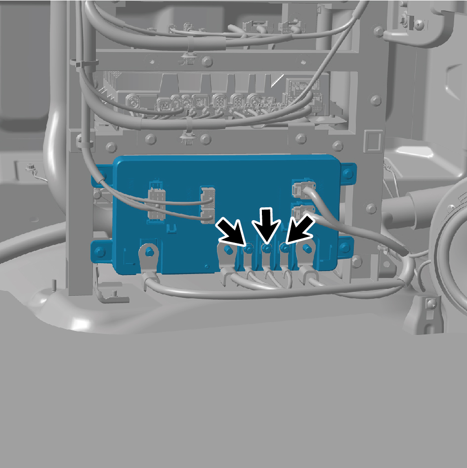
harness.
4
Connect the harness, and install 3 fixing nuts of the
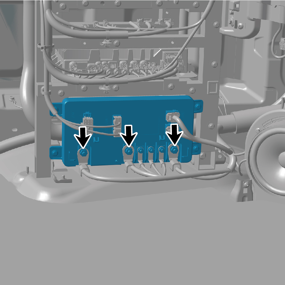
harness.
5
Install the SJB_UP cover plate, and install 1 screw.
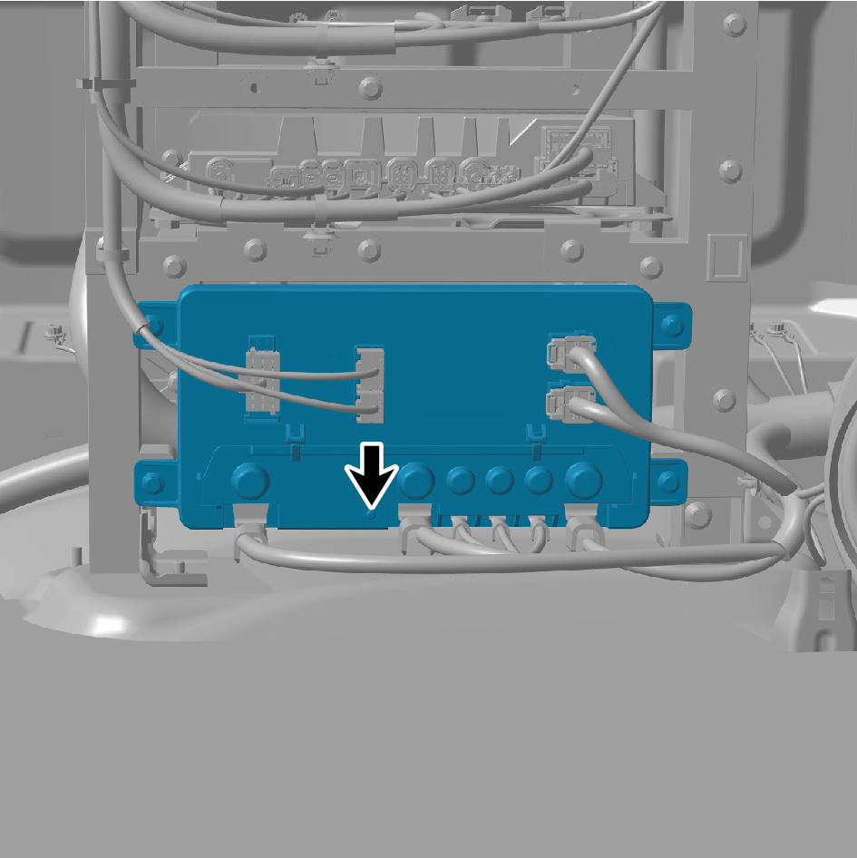
6
Connect 5 harness connectors of the SJB_UP.
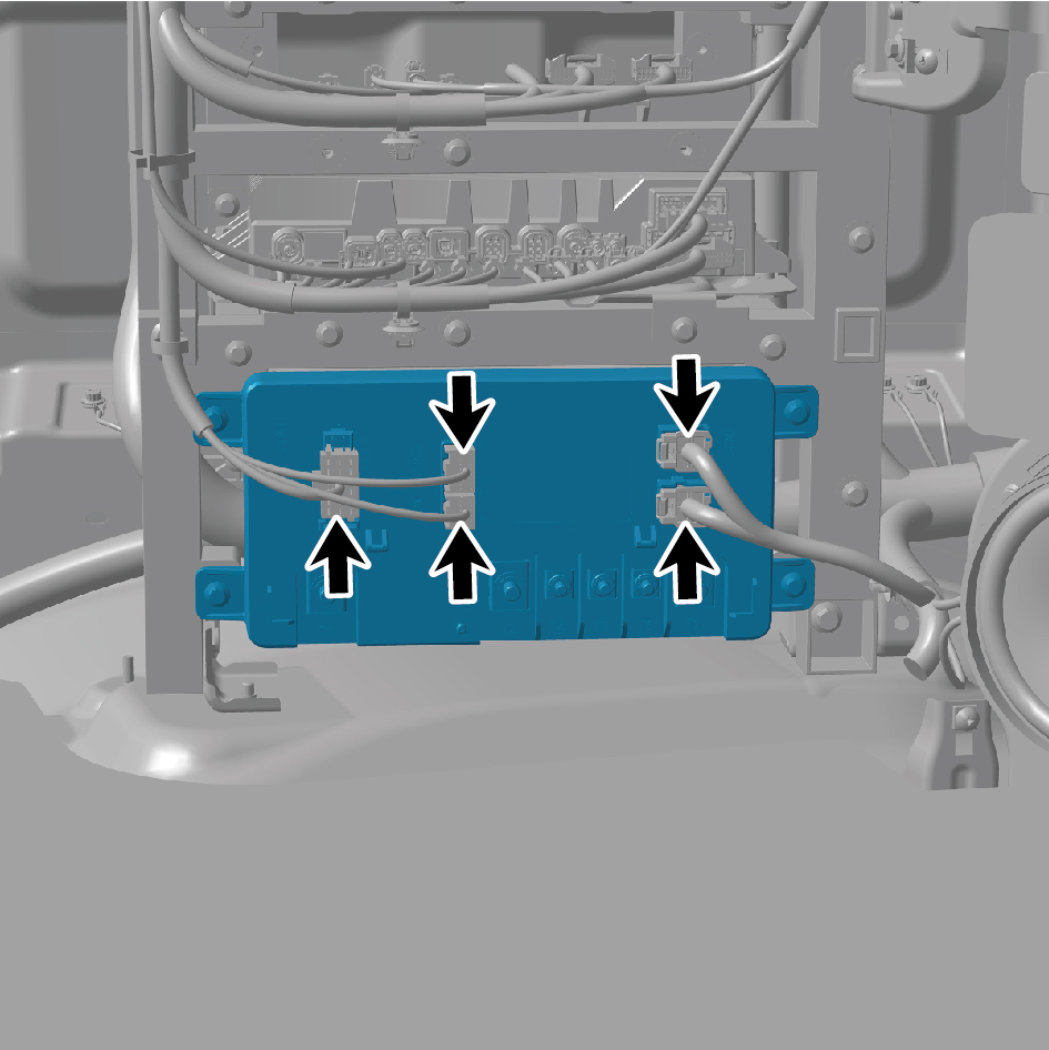
caution
The harness is firmly connected following the
principal of "insert until a click is heard for
confirmation".
7
Install the left lower fixing bracket.
8
Install the IP left lower trim panel assembly.
9
Install the left switch panel lower trim panel assembly.
10
Install the left switch panel assembly.
11
Install the IP left access cover plate assembly.
12
Install the IP left upper trim panel assembly.
13
Install the vehicle travelling data recorder bracket.
14
Install the vehicle controller assy bracket.
15
Install the front USB interface.
16
Connect the battery negative cable.
17
Close the front flip cover plate.
18
Close the door.
7.4.3.9 Replacement of SJB_UN
Removal Procedures
1
Open the door.
2
Open the front flip cover plate.
3
Disconnect the battery negative cable.
caution
power down the high-voltage system before
disconnecting the negative pole of the storage
battery.
4
Remove 4 fixing bolts of Left Junction Box, and move Left
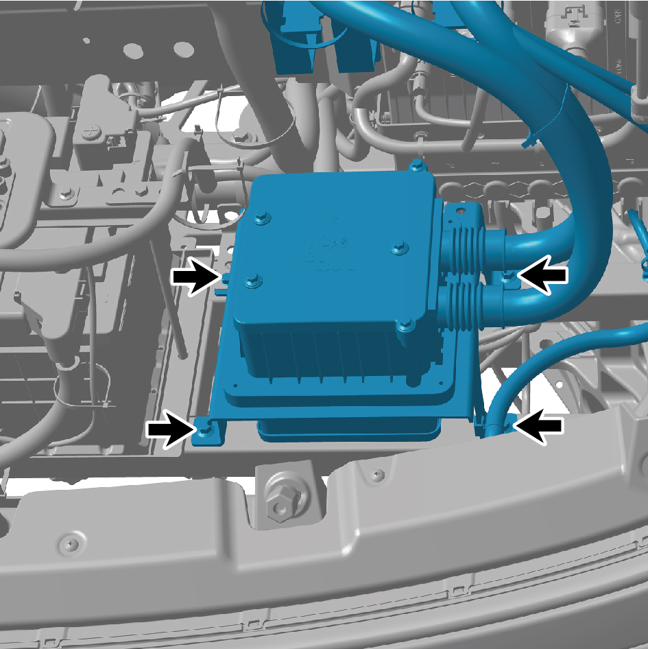
Junction Box.
5
Remove 2 fixing bolts of the SJB_UN bracket, and move
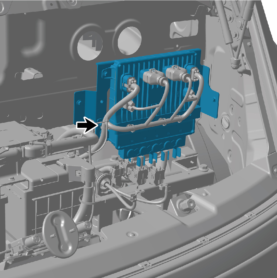
the SJB_UN bracket.
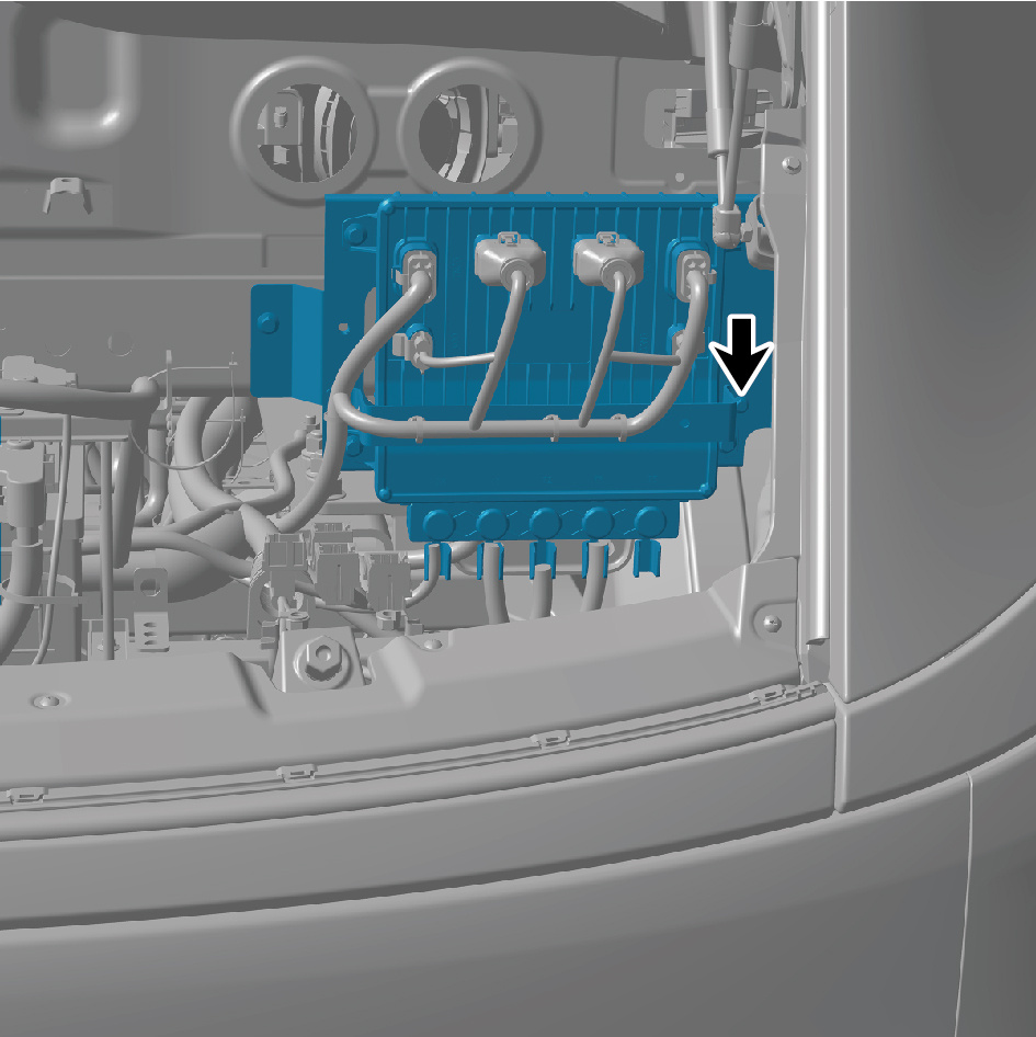
6
Remove the cover plate and remove 2 fixing bolts to
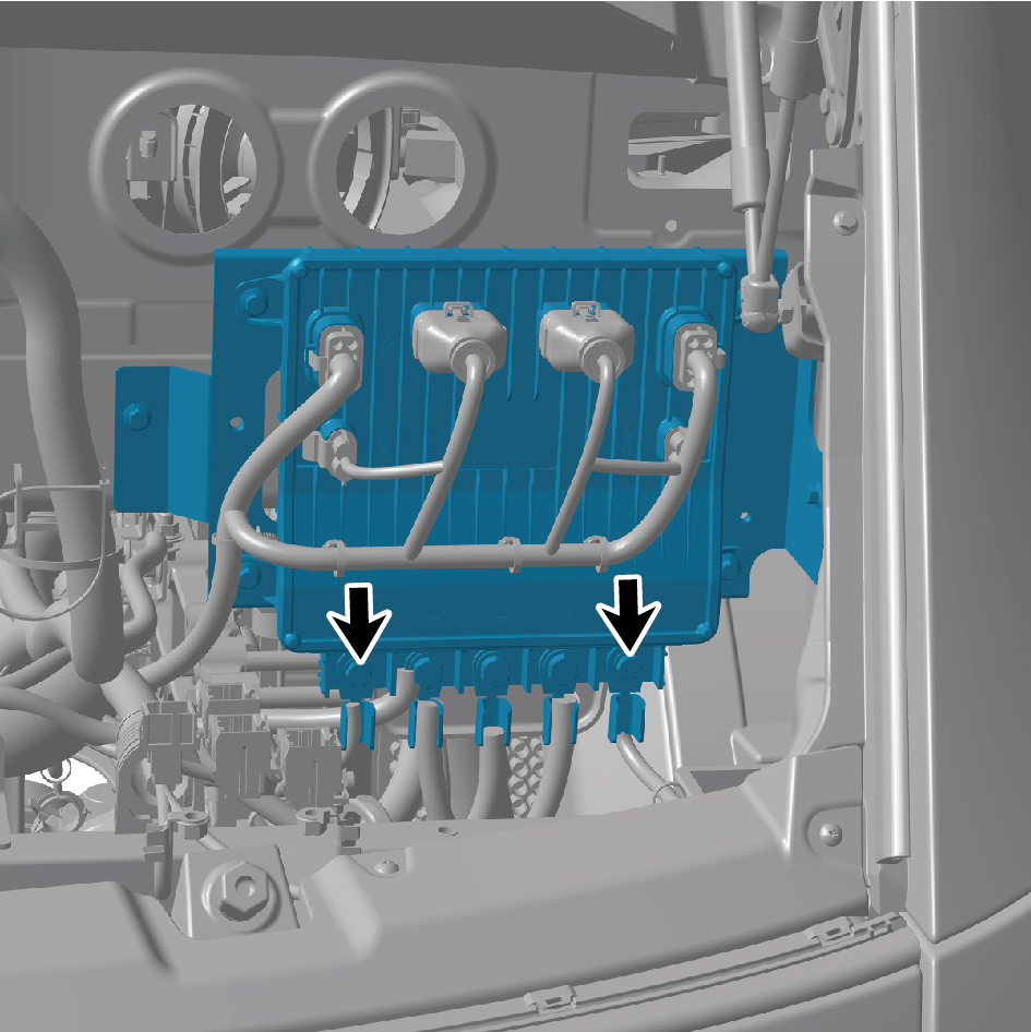
detach the harness.
7
Remove 3 fixing bolts to detach the harness.
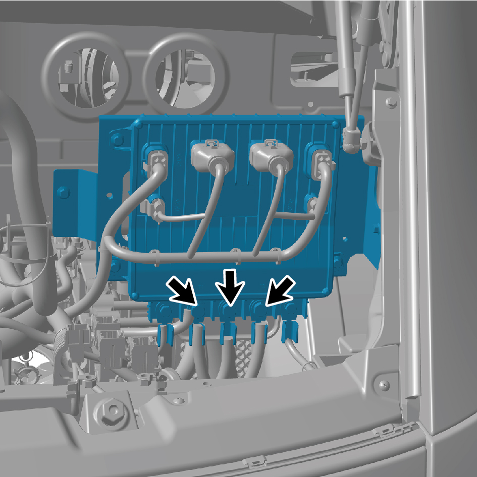
8
Disconnect 6 harness connectors of the SJB_UN.
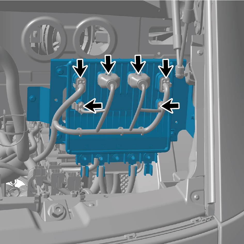
9
Remove 4 fixing bolts of the SJB_UN.
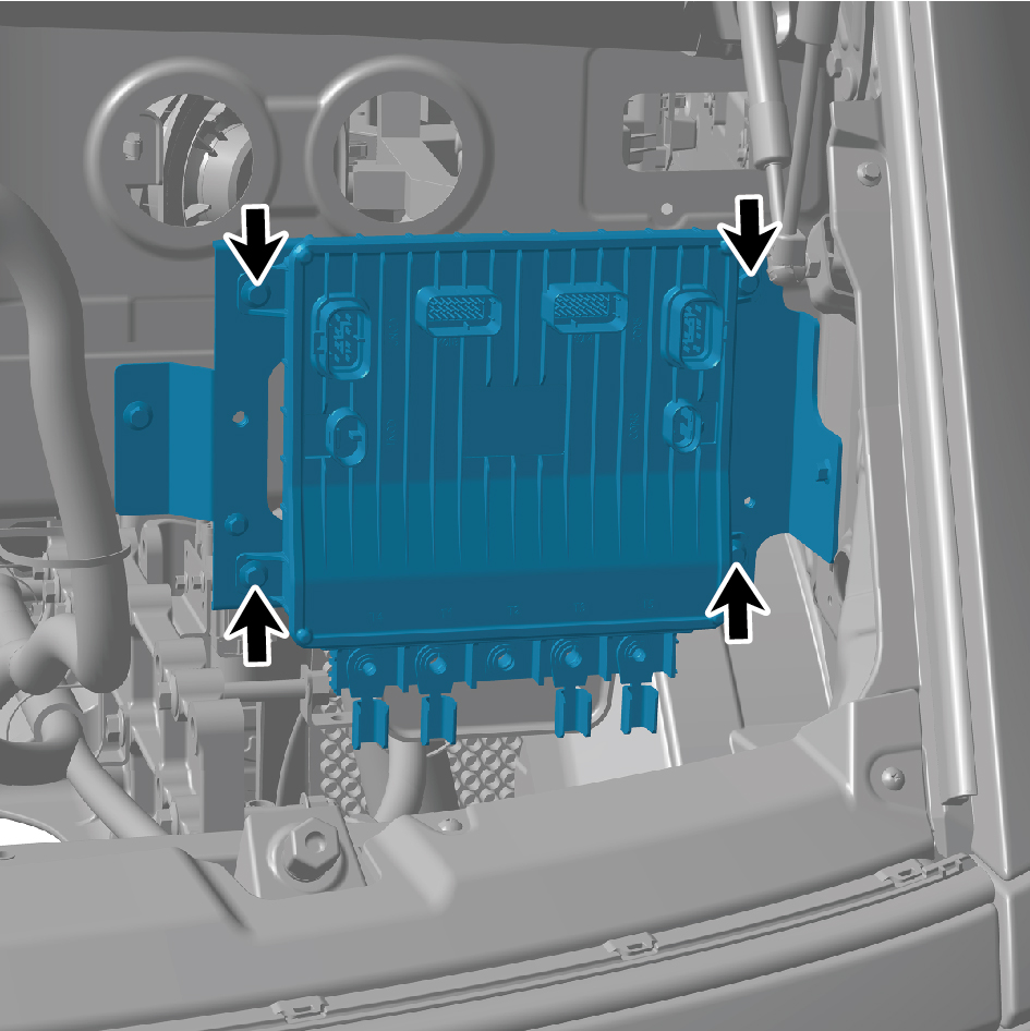
10
Remove the SJB_UN.
Installation Procedures
1
Move the SJB_UN to the mounting position.
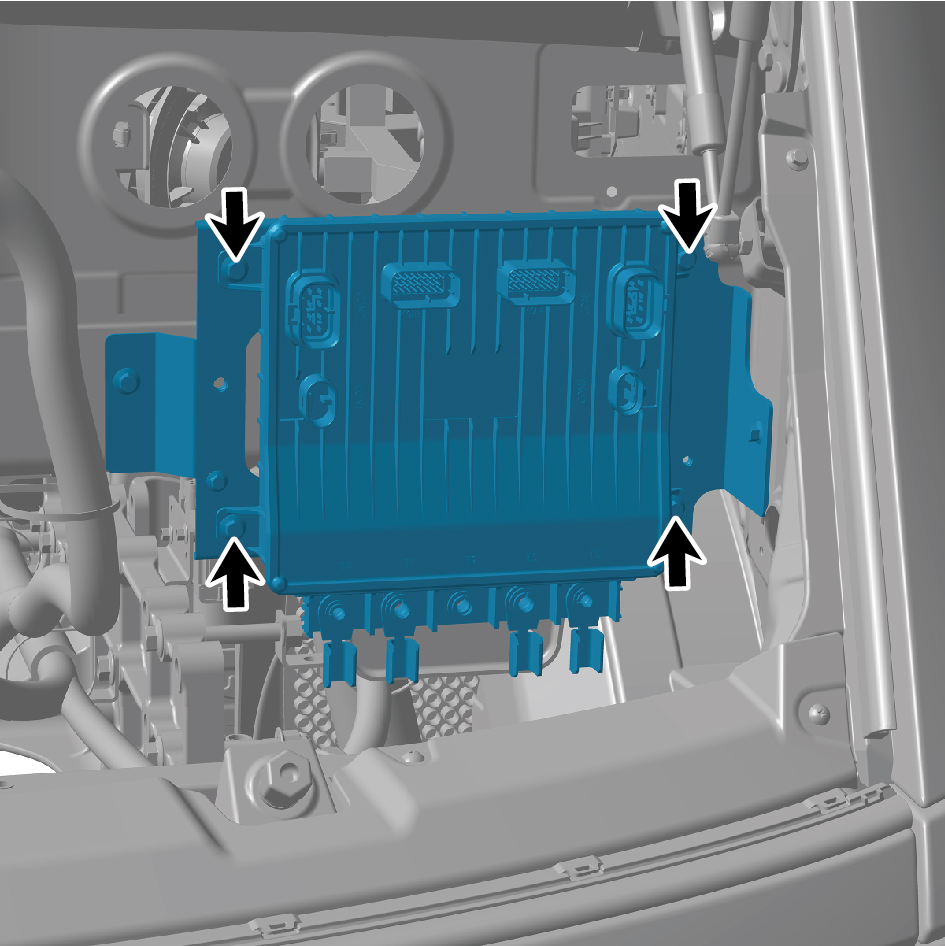
2
Install 4 fixing bolts of the SJB_UN.
Torque: (18.5 +/- 2) ft lbs
3
Connect 6 harness connectors of the SJB_UN.
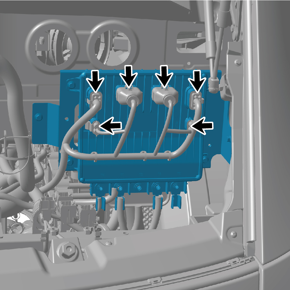
caution
The harness is firmly connected following the
principal of "insert until a click is heard for
confirmation".
4
Connect the harness, and install 3 fixing bolts.
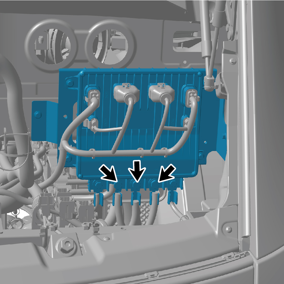
5
Connect the harness, install 2 fixing bolts, and install the
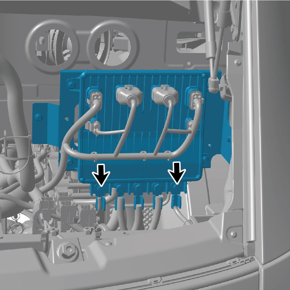
cover plate.
6
Install the SJB_UN bracket, and install 2 fixing bolts of the
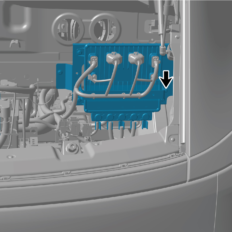
SJB_UN bracket.
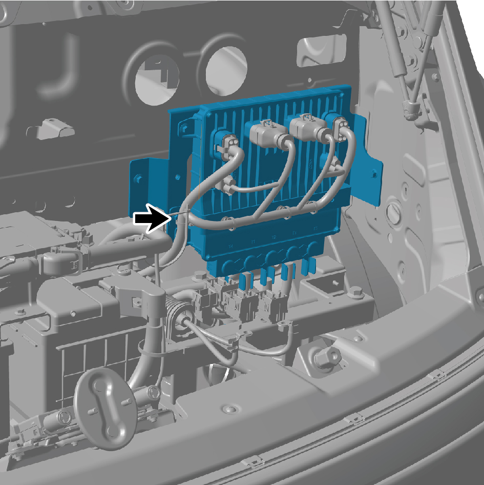
7
Install Left Junction Box, and install 4 fixing bolts of Left
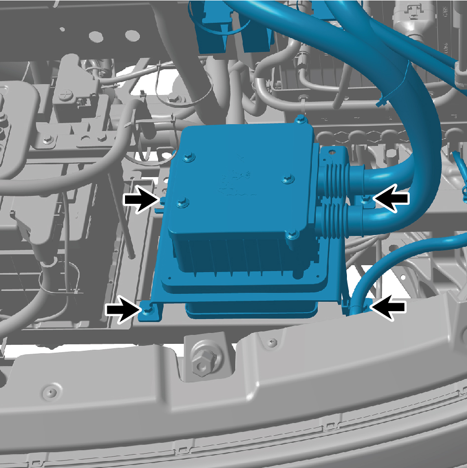
Junction Box.
8
Connect the battery negative cable.
9
Close the front flip cover plate.
10
Close the door.
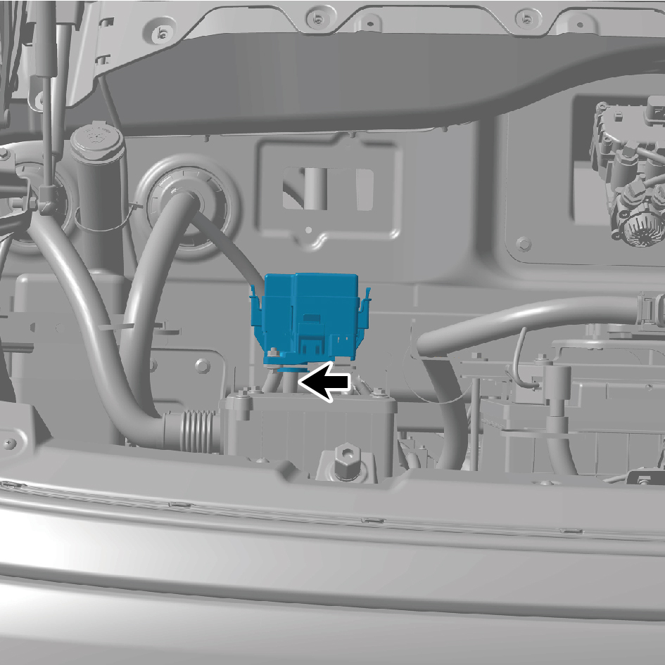
7.4.3.10 Replacement of The DC Converter
Removal procedures
1
Open the door.
2
Open the front flip cover plate.
3
Disconnect the battery negative cable.
caution
power down the high-voltage system before
disconnecting the negative pole of the storage
battery.
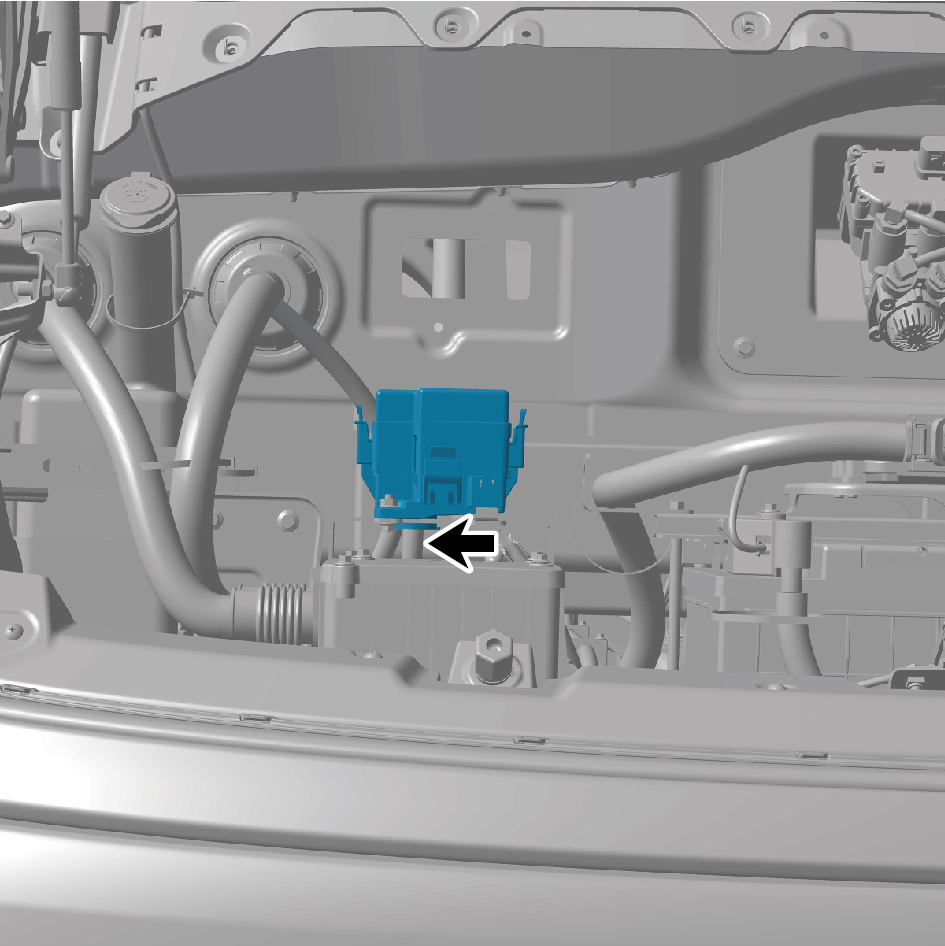
4
Disconnect 1 wire harness connector of the DC converter.
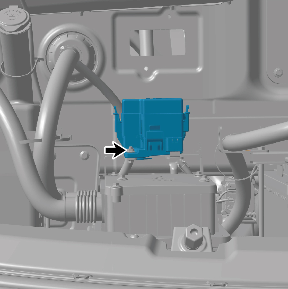
5
Remove 1 fixing bolt of the DC converter.
6
Separate the DC converter from the DC converter
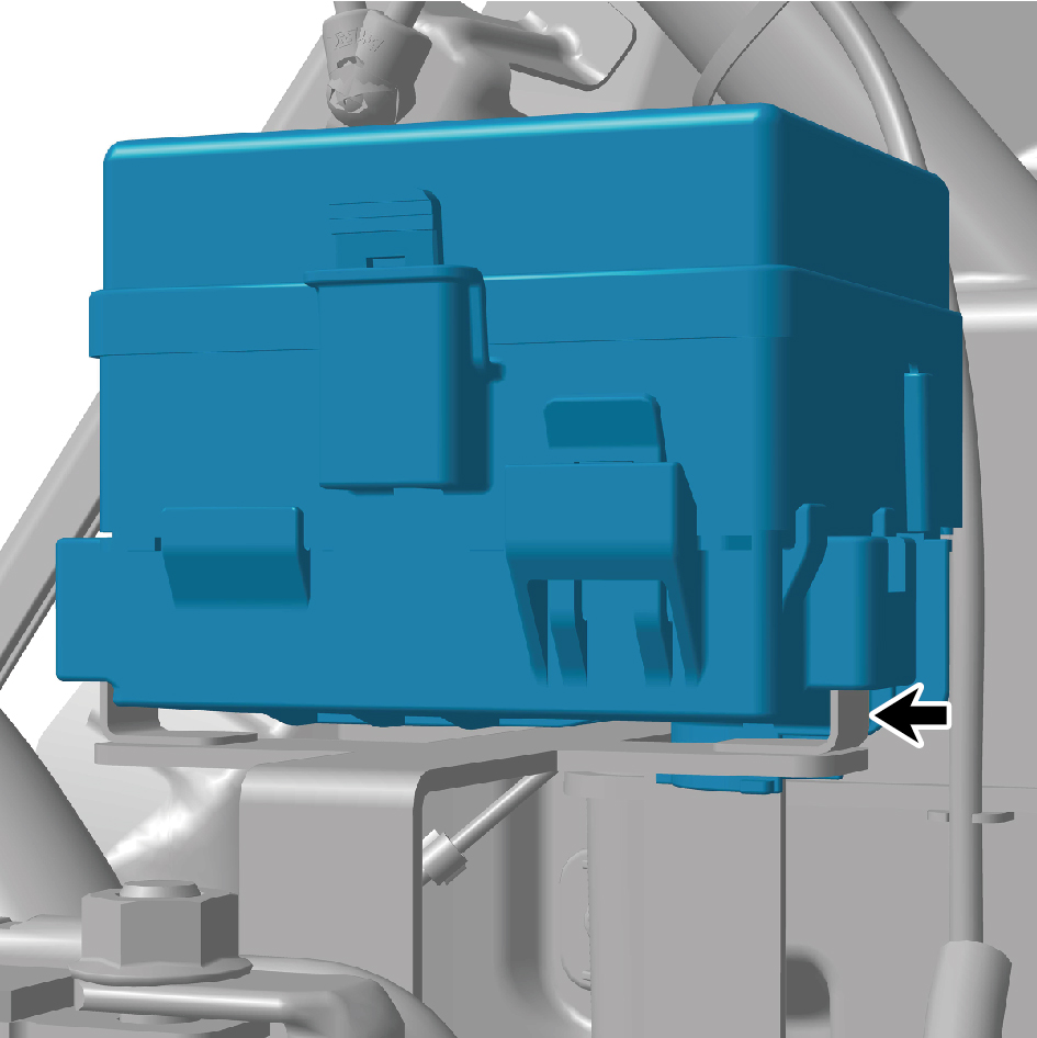
bracket.
7
Remove the DC converter.
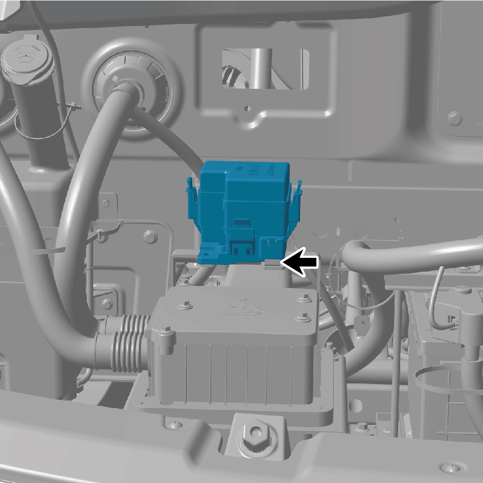
Installation procedures
1
Move the DC converter to the mounting position.
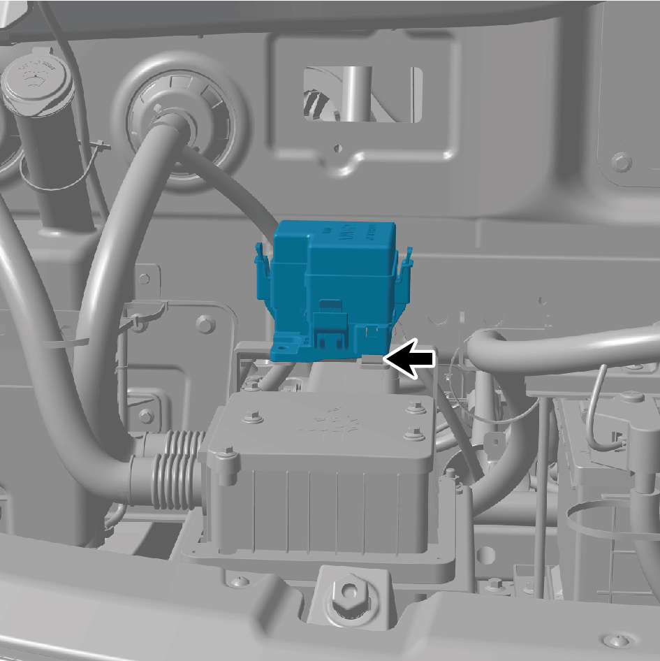
2
Connect the DC converter to the DC converter bracket.
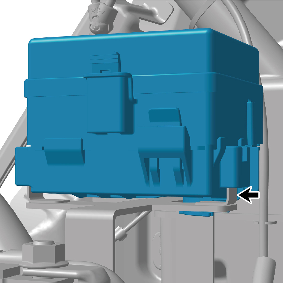
3
Install 1 fixing bolt of the DC converter.
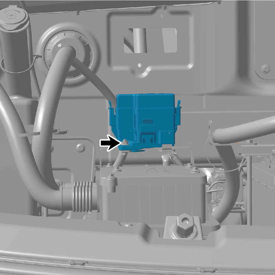
4
Connect 1 wire harness connector of the DC converter.
caution
The harness is firmly connected following the
principal of "insert until a click is heard for
confirmation".
5
Connect the battery negative cable.
6
Close the front flip cover plate.
7
Close the door.
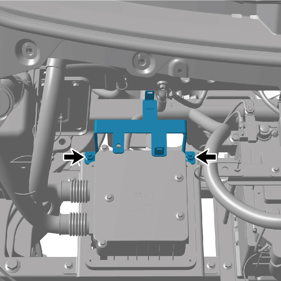
7.4.3.11 Replacement of The DC Converter Bracket
Bracket
Removal procedures
1
Open the door.
2
Open the front flip cover plate.
3
Disconnect the battery negative cable.
caution
power down the high-voltage system before
disconnecting the negative pole of the storage
battery.
4
Remove the DC converter.
5
Remove 2 fixing nuts of the DC converter bracket.
6
Remove the DC converter bracket.
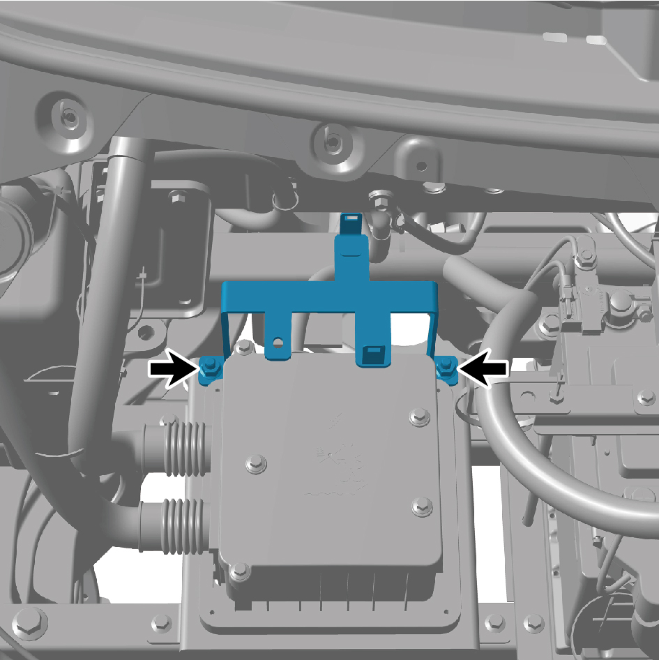
Installation procedures
1
Move the DC converter bracket to the mounting position.
2
Install 2 fixing nuts of the DC converter bracket.
3
Install the DC converter.
4
Connect the battery negative cable.
5
Close the front flip cover plate.
6
Close the door.
7.4.4 Inspect
7.4.4.1 Inspection Of The Main Battery
Step 1
Check the appearance of the main battery.
A.
Check the appearance of the main battery for
deformation or damage.
B.
Check if the main battery is leaking.
C.
Confirm if the above checks are normal.
Refer to Replacement Of Auxiliary
Battery
Yes
Step 2
Check the positive and negative connectors of the main battery.
A.
Check whether the positive and negative connectors of
the main battery are loose, oxidized, or corroded.
B.
Confirm if the above checks are normal.
Repair or replace faulty components.
Yes
Use a battery tester to test the main battery.
Step 3
A.
Set the vehicle power to OFF for multimedia.
B.
Disconnect the positive and negative terminals of the
main battery.
C.
Use a battery tester to measure the main battery and
perform the corresponding operations according to the
table below.
Measurement Result
Execution Operations
The battery is in good
Inspection completed
condition
Need to charge
Charge the main battery
Refer to Replacement Of
Need to replace
Auxiliary Battery
7.4.5 System Schematic Diagram
7.4.5.1 Electrical Schematic Diagram
Body smart electrical box
Chassis smart electrical box
12V power distribution system
7.4.6 Diagnostic Information and Steps
7.4.6.1 Diagnostic Description
Before diagnosing the fault of the battery device, it is important to understand and familiarize oneself with the working principle of
the battery device before starting the system diagnosis. This will help determine the correct fault diagnosis steps when a fault
occurs, and more importantly, it will help determine the situation described by the customer belongs to normal operation. Any
fault diagnosis of battery devices should start with routine inspection, guiding maintenance personnel to take the next logical step
for fault diagnosis. Understanding and correctly using the diagnostic process can shorten the diagnosis time and avoid
misjudgment of faulty parts.
7.4.6.2 Routine Inspection
• Check for aftermarket devices that may affect the operation of the battery system, ensuring that these devices do not affect the
operation of the battery system.
• Check system components that are easily accessible or visible to ensure that there is no obvious damage or potential
malfunction.
7.4.6.3 DTC Confirmation
1. Connect the diagnostic tool to the diagnostic interface, read and record the DTC, and then clear the DTC.
2. Run the vehicle again.
3. Read the fault code of the control system again to confirm if there is any fault code output from the system.
– Yes:Diagnose based on the output fault code.
– No:Perform intermittent fault check, refer to Inspection Of Intermittent Faults
7.4.6.4 List Of Diagnostic Trouble Codes (DTC)
SJBUP
Fault Description
Exclusion Method
Fault Code
Refer to Smart Junction Box UP Power
Module overvoltage
B180017
Fault
Communication with the BDCU timed
U014087
out
U007C88
BCANFD1 BusOff
BCANFD1 NM Limphome
U220600
Refer to Smart Junction Box UP
High battery voltage
B111717
Communication Fault
Low Battery Voltage
B111716
U015687
Lost Communication With CDCU
U019887
Lost Communication With T-Box
U012287
Lost Communication With VDC
OUT07:KL15 load open circuit
B180713
Refer to Smart Junction Box UP KL15
B180719
OUT07:KL15 overcurrent
Main Power Supply Circuit Fault
OUT07:KL15 over temperature
B18074B
OUT01:Rear Blower load open circuit
B180113
Refer to Power Supply Circuit Fault Of
B180119
OUT01:Rear Blower overcurrent
Sleeper Air Conditioning Blower
OUT01:Rear Blower over temperature
B18014B
OUT02:Right Front Blower load open
B180213
Refer to Right Air Conditioning Blower
circuit
Power Supply Circuit Fault
OUT02:Right Front Blower overcurrent
B180219
Fault Description
Exclusion Method
Fault Code
OUT02:Right Front Blower over
B18024B
temperature
OUT03:Left Front Blower load open
B180313
circuit
Refer to Left Air Conditioning Blower
B180319
OUT03:Left Front Blower overcurrent
Power Supply Circuit Fault
OUT03:Left Front Blower over
B18034B
temperature
OUT05:SWC load open circuit
B180513
Refer to Seat Module Power Supply
B180519
OUT05:SWC overcurrent
Circuit Fault
OUT05:SWC over temperature
B18054B
OUT06:Body BDCU1 load open circuit
B180613
OUT06:Body BDCU1 overcurrent
B180619
OUT06:Body BDCU1 over temperature
B18064B
Refer to Vehicle Domain Controller
Power Supply Circuit Fault
OUT11:Body BDCU2 load open circuit
B180B13
OUT11:Body BDCU2 overcurrent
B180B19
OUT11:Body BDCU2 over temperature
B180B4B
OUT08:CDCU load open circuit
B180813
Refer to Cabin Domain Controller Power
B180819
OUT08:CDCU overcurrent
Supply Circuit Fault
OUT08:CDCU over temperature
B18084B
OUT09:ECAS load open circuit
B180913
Refer to ECAS Power Supply Circuit
B180919
OUT09:ECAS overcurrent
Fault
OUT09:ECAS over temperature
B18094B
OUT10:DCM load open circuit
B180A13
Refer to Power Supply Circuit Fault Of
B180A19
OUT10:DCM overcurrent
Door Control Module
OUT10:DCM over temperature
B180A4B
OUT12:Sky Shade CurIntel load open
B180C13
circuit
Refer to Fault In The Power Supply
OUT12:Sky Shade CurIntel overcurrent
B180C19
Circuit Of The Sunroof Sunshade
OUT12:Sky Shade CurIntel over
B180C4B
temperature
OUT14:Work load open circuit
B180E13
Refer to Power Supply Circuit Fault Of
B180E19
OUT14:Work overcurrent
Switch Type Power Supply
OUT14:Work over temperature
B180E4B
OUT17:IPC load open circuit
B181113
Refer to Instrument Panel Power Supply
B181119
OUT17:IPC overcurrent
Circuit Fault
OUT17:IPC over temperature
B18114B
OUT18:OBD load open circuit
B181213
Refer to OBD Power Supply Circuit
B181219
OUT18:OBD overcurrent
Fault
OUT18:OBD over temperature
B18124B
Fault Description
Exclusion Method
Fault Code
OUT19:ACAndBatCompressor load
B181313
open circuit
Refer to Compressor Power Supply
OUT19:ACAndBatCompressor
B181319
Circuit Fault
overcurrent
OUT19:ACAndBatCompressor over
B18134B
temperature
OUT21:PTC load open circuit
B181513
Refer to PTC Power Supply Circuit Fault
B181519
OUT21:PTC overcurrent
OUT21:PTC over temperature
B18154B
OUT22:AC load open circuit
B181613
Refer to Air Conditioning Controller
B181619
OUT22:AC overcurrent
Power Supply Circuit Fault
OUT22:AC over temperature
B18164B
OUT23:FrontUSB load open circuit
B181713
Refer to Front Row USB Power Supply
B181719
OUT23:FrontUSB overcurrent
Circuit Fault
OUT23:FrontUSB over temperature
B18174B
OUT24:RearUSB load open circuit
B181813
Refer to Rear USB Power Supply Circuit
B181819
OUT24:RearUSB overcurrent
Fault
OUT24:RearUSB over temperature
B18184B
OUT26:AR_HUD load open circuit
B181A13
Refer to HUD Power Supply Circuit
OUT26:AR_HUD overcurrent
B181A19
Fault
OUT26:AR_HUD over temperature
B181A4B
OUT29:PWC load open circuit
B181D13
Refer to Wireless Charging Module
B181D19
OUT29:PWC overcurrent
Power Supply Circuit Fault
OUT29:PWC over temperature
B181D4B
OUT32:TV load open circuit
B182013
Refer to Vehicle Mounted TV Power
B182019
OUT32:TV overcurrent
Supply Circuit Fault
OUT32:TV over temperature
B18204B
OUT33:ESCL load open circuit
B182113
Refer to ESCL Power Supply Circuit
B182119
OUT33:ESCL overcurrent
Fault
OUT33:ESCL over temperature
B18214B
OUT34_Sleeper switch devices open
B182213
circuit
Refer to Sleeper Switch Devices Power
Supply Circuit Fault
B182219
OUT34:SSM overcurrent
OUT34:SSM over temperature
B18224B
OUT35:CAR load open circuit
B182313
Refer to CAR Screen Power Supply
B182319
OUT35:CAR overcurrent
Circuit Fault
OUT35:CAR over temperature
B18234B
OUT36:IVI load open circuit
B182413
Refer to IVI Screen Power Supply
Circuit Fault
B182419
OUT36:IVI overcurrent
Fault Description
Exclusion Method
Fault Code
OUT36:IVI over temperature
B18244B
OUT38:BatDrivPump1 load open circuit
B182613
Refer to Left Battery Water Pump Power
OUT38:BatDrivPump1 overcurrent
B182619
Supply Circuit Fault
OUT38:BatDrivPump1 over
B18264B
temperature
OUT47:BatDrivPump2 load open circuit
B182F13
Refer to Right Battery Water Pump
OUT47:BatDrivPump2 overcurrent
B182F19
Power Supply Circuit Fault
OUT47:BatDrivPump2 over
B182F4B
temperature
OUT42:VertMotorDrivPump1 load open
B182A13
circuit
Refer to Power Supply Circuit Fault Of
OUT42:VertMotorDrivPump1
B182A19
Motor Water Pump 1
overcurrent
OUT42:VertMotorDrivPump1 over
B182A4B
temperature
OUT43:VertMotorDrivPump2 load open
B182B13
circuit
Refer to Fault In The Power Supply
OUT43:VertMotorDrivPump2
B182B19
Crcuit Of Motor Water Pump 2
overcurrent
OUT43:VertMotorDrivPump2 over
B182B4B
temperature
OUT39:BatFanGuard1 load open circuit
B182713
Refer to Left Battery Fan 1 Power
B182719
OUT39:BatFanGuard1 overcurrent
Supply Circuit Fault
OUT39:BatFanGuard1 over
B18274B
temperature
OUT40:BatFanGuard2 load open circuit
B182813
Refer to Left Battery Fan 2 Power
B182819
OUT40:BatFanGuard2 overcurrent
Supply Circuit Fault
OUT40:BatFanGuard2 over
B18284B
temperature
OUT46:BatFanGuard3 load open circuit
B182E13
Refer to Right Battery Fan 1 Power
B182E19
OUT46:BatFanGuard3 overcurrent
Supply Circuit Fault
OUT46:BatFanGuard3 over
B182E4B
temperature
OUT45:BatFanGuard4 load open circuit
B182D13
Refer to Right Battery Fan 2 Power
B182D19
OUT45:BatFanGuard4 overcurrent
Supply Circuit Fault
OUT45:BatFanGuard4 over
B182D4B
temperature
OUT41:AlterFanGuard1 load open
B182913
Refer to Motor Fan 1 Power Supply
circuit
Circuit Fault
B182919
OUT41:AlterFanGuard1 overcurrent
Fault Description
Exclusion Method
Fault Code
OUT41:AlterFanGuard1 over
B18294B
temperature
OUT44:AlterFanGuard2 load open
B182C13
circuit
Refer to Motor Fan 2 Power Supply
B182C19
OUT44:AlterFanGuard2 overcurrent
Circuit Fault
OUT44:AlterFanGuard2 over
B182C4B
temperature
OUT37:AlterFanGuard3 load open
B182513
circuit
Refer to Motor Fan 3 Power Supply
B182519
OUT37:AlterFanGuard3 overcurrent
Crcuit Fault
OUT37:AlterFanGuard3 over
B18254B
temperature
SJBUN
Fault Description
Exclusion Method
Fault Code
High battery voltage
B111717
Refer to Smart Junction Box DOWN
Low Battery Voltage
B111716
Power Fault
Module overvoltage
B1E0017
Communication with the BDCU timed
U014087
out
U007C88
BCANFD1 BusOff
BCANFD1 NM Limphome
U220600
U015687
Lost Communication With CDCU
Refer to Smart Junction Box DOWN
Lost Communication With SJB_UP
U01A087
Communication Fault
U019887
Lost Communication With T-Box
U012287
Lost Communication With VDC
U007D88
BCANFD2 BusOff
BCANFD2 NM Limphome
U220700
OUT01:Body load open circuit
B1E0113
Refer to Fault In The Main Power Supply
OUT01:Body overcurrent
B1E0119
Circuit Of The Vehicle Body
OUT01:Body over temperature
B1E014B
OUT03:EPS load open circuit
B1E0313
B1E0319
OUT03:EPS overcurrent
OUT03:EPS over temperature
B1E034B
Refer to EPS Power Supply Circuit Fault
OUT29:EPSAssist load open circuit
B1E1D13
B1E1D19
OUT29:EPSAssist overcurrent
OUT29:EPSAssist over temperature
B1E1D4B
OUT04:KL15_1 load open circuit
B1E0413
Refer to Smart Junction Box DOWN
OUT04:KL15_1 overcurrent
B1E0419
KL15 Main Power Supply Circuit Fault
OUT04:KL15_1 over temperature
B1E044B
Fault Description
Exclusion Method
Fault Code
OUT34:KL15_3 load open circuit
B1E2213
OUT34:KL15_3 overcurrent
B1E2219
OUT34:KL15_3 over temperature
B1E224B
OUT05:EBSKL30 load open circuit
B1E0513
B1E0519
OUT05:EBSKL30 overcurrent
OUT05:EBSKL30 over temperature
B1E054B
OUT10:EBS_KL15 load open circuit
B1E0A13
OUT10:EBS_KL15 overcurrent
B1E0A19
OUT10:EBS_KL15 over temperature
B1E0A4B
Refer to EBS Power Supply Circuit Fault
OUT31-EBS trailer open circuit
B1E1F13
B1E1F19
OUT31:TrailerEBS overcurrent
OUT31:TrailerEBS over temperature
B1E1F4B
OUT33:EBSBat30 load open circuit
B1E2113
B1E2119
OUT33:EBSBat30 overcurrent
OUT33:EBSBat30 over temperature
B1E214B
OUT08:MediumaxleTCU load open
B1E0813
circuit
Refer to Electric Drive Medium axle
B1E0819
OUT08:MediumaxleTCU overcurrent
TCU Power Supply Circuit Fault
OUT08:MediumaxleTCU over
B1E084B
temperature
OUT09:TGWBat load open circuit
B1E0913
B1E0919
OUT09:TGWBat overcurrent
OUT09:TGWBat over temperature
B1E094B
Refer to Gateway Power Supply Circuit
Fault
OUT38:TGWAssist load open circuit
B1E2613
B1E2619
OUT38:TGWAssist overcurrent
OUT38:TGWAssist over temperature
B1E264B
OUT11:BackupLamp load open circuit
B1E0B13
Refer to Reverse Light Power Supply
OUT11:BackupLamp overcurrent
B1E0B19
Circuit Fault
OUT11:BackupLamp over temperature
B1E0B4B
OUT13:TractorMarkerLight load open
B1E0D13
circuit
Refer to Small Lamp Power Supply
OUT13:TractorMarkerLight overcurrent
B1E0D19
Circuit Fault
OUT13:TractorMarkerLight over
B1E0D4B
temperature
OUT17:LeftLowBeam load open circuit
B1E1113
Refer to Left Low Beam Lamp Power
B1E1119
OUT17:LeftLowBeam overcurrent
Supply Circuit Fault
OUT17:LeftLowBeam over temperature
B1E114B
Refer to Right High Beam Power Supply
OUT18_ Right high beam open circuit
B1E1213
Circuit Fault
Fault Description
Exclusion Method
Fault Code
OUT18:TractorRightHighBeam
B1E1219
overcurrent
OUT18:TractorRightHighBeam over
B1E124B
temperature
OUT19:TractorLeftHighBeam load open
B1E1313
circuit
OUT19:TractorLeftHighBeam
Refer to Left High Beam Power Supply
B1E1319
overcurrent
Circuit Fault
OUT19:TractorLeftHighBeam over
B1E134B
temperature
OUT20:RightLowBeam load open
B1E1413
circuit
Refer to Right Low Beam Power Supply
OUT20:RightLowBeam overcurrent
B1E1419
Circuit Fault
OUT20_ Right low beam overheating
B1E144B
OUT22:LeftRunning load open circuit
B1E1613
Refer to Left Daytime Running Light
OUT22:LeftRunning overcurrent
B1E1619
Power Supply Circuit Fault
OUT22:LeftRunning over temperature
B1E164B
OUT24:RightRunning load open circuit
B1E1813
Refer to Right Daytime Running Light
OUT24:RightRunning overcurrent
B1E1819
Power Supply Circuit Fault
OUT24:RightRunning over temperature
B1E184B
OUT27:WorkingLights load open circuit
B1E1B13
Refer to Rear Work Light Power Supply
OUT27:WorkingLights overcurrent
B1E1B19
Circuit Fault
OUT27:WorkingLights over temperature
B1E1B4B
OUT35: EPB load open circuit
B1E1E13
Refer to EPB Power Supply Circuit Fault
B1E1E19
OUT35: EPB overcurrent
OUT35:EPB over temperature
B1E1E4B
OUT37:VDCB load open circuit
B1E2513
Refer to VDC Power Supply Circuit Fault
B1E2519
OUT37:VDCB overcurrent
OUT37:VDCB over temperature
B1E254B
OUT39:MediumRearaxleTCU load
B1E2713
open circuit
Refer to Fault In The Power Supply
OUT39:MediumRearaxleTCU
B1E2719
Circuit Of The Rear Axle MCU In The
overcurrent
Electric Drive
OUT39:MediumRearaxleTCU over
B1E274B
temperature
OUT40:AirHandlingUnit load open
B1E2813
Refer to Fault In The Power Supply
circuit
Circuit Of The Air Handling Unit
OUT40:AirHandlingUnit overcurrent
B1E2819
Fault Description
Exclusion Method
Fault Code
OUT40:AirHandlingUnit over
B1E284B
temperature
OUT41:HighLowPitchElectricHorn load
B1E2913
open circuit
Refer to Electric Horn Power Supply
OUT41:HighLowPitchElectricHorn
B1E2919
Circuit Fault
overcurrent
OUT41:HighLowPitchElectricHorn over
B1E294B
temperature
OUT47:AirHorn load open circuit
B1E2F13
Refer to Fault In The Power Supply
B1E2F19
OUT47:AirHorn overcurrent
Circuit Of The Gas Horn
OUT47:AirHorn over temperature
B1E2F4B
OUT44:Battery pack load open circuit
B1E2C13
Refer to Battery Pack Power Supply
OUT44:Battery pack overcurrent
B1E2C19
Circuit Fault
OUT44:Battery pack over temperature
B1E2C4B
OUT45:AuxiDrivMultiOne load open
B1E2D13
circuit
Refer to Power Distribution Unit Power
B1E2D19
OUT45:AuxiDrivMultiOne overcurrent
Supply Circuit Fault
OUT45:AuxiDrivMultiOne over
B1E2D4B
temperature
OUT46:BatWaterHeatComp load open
B1E2E13
circuit
Refer to Fault In The Power Supply
OUT46:BatWaterHeatComp overcurrent
B1E2E19
Circuit Of The Battery Water Heater
OUT46:BatWaterHeatComp over
B1E2E4B
temperature
OUT42:AVAS load open circuit
B1E2A13
Refer to Low Speed Pedestrian Alarm
B1E2A19
OUT42:AVAS overcurrent
Power Supply Circuit Fault
OUT42:AVAS over temperature
B1E2A4B
OUT48:TPMS load open circuit
B1E3013
Refer to Tire Pressure Power Supply
B1E3019
OUT48:TPMS overcurrent
Circuit Fault
OUT48:TPMS over temperature
B1E304B
OUT49:ChassisSensors load open
B1E3113
circuit
Refer to Chassis Sensor Power Supply
B1E3119
OUT49:ChassisSensors overcurrent
Circuit Fault
OUT49:ChassisSensors over
B1E314B
temperature
7.4.6.5 Action Test List
By reading the "Action Test" on the fault diagnosis instrument, the working status of relays and actuators controlled by SJBUN
can be checked without disassembling any components. Before conducting relevant fault diagnosis on the control system,
performing action testing is a prerequisite for troubleshooting, which can shorten the time for troubleshooting.
Note
The following table lists the data under normal conditions for reference only. Do not rely solely on these reference
values to determine whether a certain component has malfunctioned. Under normal circumstances, a comparison
can be made between a functioning vehicle and a diagnosed vehicle in the same state to determine the data of the
diagnosed vehicle is normal in its current state.
a.Perform vehicle power on operation.
b.Connect the fault diagnosis device.
c.Select "SJBUN"/"Action Test".
d.Refer to the table below and conduct active testing.
Fault Diagnosis
Control Range
Diagnostic Description
Test Parts
Instrument Display Items
Control the VDC B+power supply on/off
Output channel control -
VDC
On/Off
according to the diagnostic instrument
VBU-B+_VDC
instructions
According to the diagnostic instrument
Output Channel Control
Auxiliary intelligent
instructions, control the power supply of the
- Assisted Intelligent
On/Off
driving domain controller
auxiliary intelligent driving domain
Driving Domain
controller to turn on/off
According to the diagnostic instrument
Output Channel Control
Master intelligent driving
instructions, control the power supply of the
- Master Intelligent
On/Off
domain controller
main intelligent driving domain controller to
Driving Domain
turn on/off
Control the EBS power supply on/off
Output Channel Control
EBS
On/Off
according to the diagnostic instrument
- EBS Controller
instructions
Output Channel Control
According to the diagnostic instrument
KL15 power supply
- KL15-1 Main Power
instructions, control the KL15 power supply
On/Off
Supply 1
to turn on/off
Output Channel Control
Control the EHPS power supply on/off
- Steering Gear
EHPS
On/Off
according to the diagnostic instrument
Assembly
instructions
According to the diagnostic instrument
Output Channel Control
instructions, control the on/off of the
Car power supply
On/Off
- Car Power Supply
onboard power supply
According to the diagnostic instrument
Output Channel Control
Body B+
instructions, control the B+power supply of
On/Off
- Body B+
the vehicle body to turn on/off
According to the diagnostic instrument
Output Channel Control
Right brake lamp
instructions, control the power supply of the
On/Off
- Right brake lamp
right brake lamp to turn on/off
Fault Diagnosis
Control Range
Diagnostic Description
Test Parts
Instrument Display Items
According to the diagnostic instrument
Output Channel Control
instructions, control the left brake lamp
Left brake lamp
On/Off
- Left brake lamp
power supply to turn on/off
According to the diagnostic instrument
Output Channel Control
Reversing light
instructions, control the power supply of the
On/Off
- Reversing light
reversing light to turn on/off
According to the instructions of the
Output Channel Control
Reverse light
diagnostic instrument, control the power
On/Off
- Reverse light
supply of the reversing lights to turn on/off
Control the EBS power supply on/off
Output Channel Control
EBS
On/Off
according to the diagnostic instrument
- EBS power supply
instructions
According to the diagnostic instrument
Output Channel Control
instructions, control the power supply of the
Central gateway
On/Off
- Central gateway
central gateway to turn on/off
According to the diagnostic instrument
Output Channel Control
Right daytime running
instructions, control the power supply of the
- Right daytime running
On/Off
lamp
right daytime running lamp to turn on/off
lamp
According to the instructions of the
Output Channel Control
diagnostic instrument, control the power
Left daytime running lamp
- Left daytime running
On/Off
supply of the left daytime running lamp to
lamp
turn on/off
According to the diagnostic instrument
Output Channel Control
Right low beam headlight
instructions, control the power supply of the
- Right low beam
On/Off
right low beam to turn on/off
headlight
According to the diagnostic instrument
Output Channel Control
instructions, control the power supply of the
Left high beam
On/Off
- Left high beam
left high beam to turn on/off
According to the diagnostic instrument
Output Channel Control
Right high beam
instructions, control the power supply of the
On/Off
- Right high beam
right high beam to turn on/off
According to the diagnostic instrument
Output Channel Control
instructions, control the left low beam
Left low beam
On/Off
- Left low beam
power supply to turn on/off
Output Channel Control
According to the diagnostic instrument
Main intelligent driving
- Main intelligent driving
instructions, control the power supply of the
domain auxiliary power
On/Off
domain auxiliary power
main intelligent driving domain controller to
supply
supply
turn on/off
Fault Diagnosis
Control Range
Diagnostic Description
Test Parts
Instrument Display Items
Control the EBS trailer power supply on/off
Output Channel Control
EBS trailer
On/Off
according to the diagnostic instrument
- EBS trailer
instructions
Control the electronic parking power supply
Output Channel Control
Electronic parking
On/Off
on/off according to the diagnostic
- Electronic parking
instrument instructions
Output Channel Control
Control the EHPS power supply on/off
- EPS steering gear
EHPS
On/Off
according to the diagnostic instrument
assembly auxiliary
instructions
power supply
According to the diagnostic instrument
Output Channel Control
Emergency brake
instructions, control the power supply of the
- Emergency brake
On/Off
solenoid valve
emergency brake solenoid valve to turn on/
solenoid valve
off
According to the diagnostic instrument
Output Channel Control
Rear work light
instructions, control the power supply of the
On/Off
- Rear work light
rear work light to turn on/off
According to the diagnostic instrument
Output Channel Control
instructions, control the HSD power supply
HSD
On/Off
- HSD
to turn on/off
According to the diagnostic instrument
Output Channel Control
Air handling unit
instructions, control the power supply of the
On/Off
- Air handling unit
air handling unit to turn on/off
According to the diagnostic instrument
Output Channel Control
instructions, control the power supply of the
Mid/Rear axle MCU
On/Off
- Mid/Rear axle MCU
middle/rear axle MCU to turn on/off
According to the diagnostic instrument
Output Channel Control
Gateway auxiliary power
instructions, control the power supply of the
- Gateway auxiliary
On/Off
supply
central gateway to turn on/off
power supply
According to the diagnostic instrument
Output Channel Control
instructions, control the power supply of the
Middle axle TCU
On/Off
- Middle axle TCU
TCU in the middle axle to turn on/off
According to the diagnostic instrument
Output Channel Control
ADB headlights
instructions, control the ADB headlight
On/Off
- ADB headlights
power supply to turn on/off
Output Channel Control
According to the diagnostic instrument
Auxiliary intelligent
- Auxiliary intelligent
instructions, control the power supply of the
driving domain auxiliary
On/Off
driving domain auxiliary
auxiliary intelligent driving domain
power supply
power supply
controller to turn on/off
Fault Diagnosis
Control Range
Diagnostic Description
Test Parts
Instrument Display Items
Output Channel Control
Control the KL15 power supply on/off
KL15 main power supply
- KL15 main power
On/Off
according to the diagnostic instrument
3
supply 3
instructions
Control the EBS power supply on/off
Output Channel Control
EBS
On/Off
according to the diagnostic instrument
- EBS-KL30B
instructions
According to the diagnostic instrument
Output Channel Control
Tire pressure + active
instructions, control the tire pressure/active
- Tire pressure + active
On/Off
grille shutter
grille shutter power supply on/off
grille shutter
According to the diagnostic instrument
Output Channel Control
instructions, control the power supply of the
Air horn
On/Off
- Air horn
gas horn to turn on/off
According to the diagnostic instrument
Output Channel Control
Battery water heating
instructions, control the battery water
On/Off
- Battery water heating
heating power supply to turn on/off
According to the diagnostic instrument
Output Channel Control
instructions, control the on/off of the power
Power distribution unit
On/Off
- Power distribution unit
distribution unit power supply
According to the diagnostic instrument
Output Channel Control
instructions, control the battery pack power
Battery Pack
On/Off
- Battery Pack
supply to turn on/off
According to the diagnostic instrument
Output Channel Control
instructions, control the HSD power supply
HSD
On/Off
- HSD
to turn on/off
According to the diagnostic instrument
Output Channel Control
Low speed pedestrian
instructions, control the low-speed
- Low speed pedestrian
On/Off
alarm
pedestrian alarm power supply to turn on/
alarm
off
According to the diagnostic instrument
Output Channel Control
tweeter/woofer frequency
instructions, control the high/low frequency
- High/low frequency
On/Off
electric speaker
electric speaker power supply to turn on/off
electric speaker
Output Channel Control
According to the diagnostic instrument
Chassis sensor power
- Chassis sensor power
instructions, control the power supply of
On/Off
supply
supply
chassis sensors to turn on/off
By reading the "Action Test" on the fault diagnosis instrument, the working status of relays and actuators controlled by SJBUP
can be checked without disassembling any components. Before conducting relevant fault diagnosis on the control system,
performing action testing is a prerequisite for troubleshooting, which can shorten the time for troubleshooting.
Note
The following table lists the data under normal conditions for reference only. Do not rely solely on these reference
values to determine whether a certain component has malfunctioned. Under normal circumstances, a comparison
can be made between a functioning vehicle and a diagnosed vehicle in the same state to determine the data of the
diagnosed vehicle is normal in its current state.
a.Perform vehicle power on operation.
b.Connect the fault diagnosis device.
c.Choice “SJBUP”/“Action Test”.
d.Refer to the table below and conduct active testing.
Fault Diagnosis
Control Range
Diagnostic Description
Test Parts
Instrument Display Items
According to the diagnostic instrument
Vehicle Output Channel
Cockpit domain controller
instructions, control the power supply of the
Control - Cockpit domain
On/Off
cabin domain controller to turn on/off
controller
Vehicle Output Channel
According to the diagnostic instrument
KL15 power supply
Control - KL15 power
instructions, control the KL15 power supply
On/Off
supply
to turn on/off
According to the diagnostic instrument
Vehicle Output Channel
instructions, control the power supply of the
Vehicle domain control
On/Off
Control - Vehicle Domain
vehicle domain controller to turn on/off
Control-1
According to the diagnostic instrument
Vehicle Output Channel
instructions, control the power supply of the
Control - Seat control
Seat control module
On/Off
seat control module to turn on/off
module
Vehicle Output Channel
Control the 24V onboard power supply on/
24V car power supply
Control - 24V car power
On/Off
off according to the diagnostic instrument
supply
instructions
According to the diagnostic instrument
Vehicle Output Channel
instructions, control the power supply of the
Left front blower
On/Off
Control - Left front
left front blower to turn on/off
blower
According to the diagnostic instrument
Vehicle Output Channel
Right front blower
instructions, control the power supply of the
Control - Right front
On/Off
right front blower to turn on/off
blower
According to the diagnostic instrument
Vehicle Output Channel
Rear blower
On/Off
instructions, control the power supply of the
Control - Rear blower
rear blower to turn on/off
According to the diagnostic instrument
Vehicle Output Channel
Driving recorder
instructions, control the power supply of the
Control - Driving
On/Off
driving recorder to turn on/off
recorder
According to the diagnostic instrument
Vehicle Output Channel
KL30
On/Off
instructions, control the KL30 power supply
Control - Reserve KL30
to turn on/off
Fault Diagnosis
Control Range
Diagnostic Description
Test Parts
Instrument Display Items
According to the diagnostic instrument
Vehicle Output Channel
instructions, control the on/off of the switch
Switching power supply
Control - Switching
On/Off
type power supply power supply
power supply
According to the diagnostic instrument
Vehicle Output Channel
Electric steps
instructions, control the power supply of the
On/Off
Control - Electric steps
electric step to turn on/off
According to the diagnostic instrument
Vehicle Output Channel
instructions, control the power supply of the
Sunroof sunshade
On/Off
Control - Sunroof
sunroof sunshade to turn on/off
sunshade
According to the diagnostic instrument
Vehicle Output Channel
instructions, control the power supply of the
Vehicle domain controller
On/Off
Control - Vehicle domain
vehicle domain controller to turn on/off
controller -2
According to the diagnostic instrument
Vehicle Output Channel
instructions, control the power supply of the
Gate control module
On/Off
Control - Gate control
door control module to turn on/off
module
Control the ECAS power supply on/off
Vehicle Output Channel
ECAS
On/Off
according to the diagnostic instrument
Control - ECAS
instructions
According to the diagnostic instrument
Vehicle Output Channel
instructions, control the rear USB power
Control - Rear USB
Rear USB power supply
On/Off
supply to turn on/off
power supply
According to the diagnostic instrument
Vehicle Output Channel
Front row USB power
instructions, control the front row USB
Control - Front row USB
On/Off
supply
power supply to turn on/off
power supply
According to the diagnostic instrument
Vehicle Output Channel
Air conditioning controller
instructions, control the power supply of the
Control - Air conditioning
On/Off
air conditioning controller to turn on/off
controller
According to the diagnostic instrument
Vehicle Output Channel
instructions, control the PTC controller
PTC controller
On/Off
Control - PTC controller
power supply to turn on/off
According to the diagnostic instrument
Vehicle Output Channel
The cigarette lighter
instructions, control the power supply of the
Control - The cigarette
On/Off
cigarette lighter to turn on/off
lighter
Vehicle Output Channel
According to the diagnostic instrument
Air
Control - Air
instructions, control the compressor power
On/Off
conditioning&compressor
conditioning&compress-
supply to turn on/off
Control the OBD interface power supply
Vehicle Output Channel
OBD interface
On/Off
on/off according to the diagnostic
Control - OBD interface
instrument instructions
Fault Diagnosis
Control Range
Diagnostic Description
Test Parts
Instrument Display Items
According to the diagnostic instrument
Vehicle Output Channel
instructions, control the power supply of the
Instrument screen
On/Off
Control - Instrument
instrument panel to turn on/off
screen
According to the diagnostic instrument
Vehicle Output Channel
instructions, control the power supply of the
Car TV
On/Off
Control - Car TV
car TV to turn on/off
According to the diagnostic instrument
Vehicle Output Channel
instructions, control the power supply of the
Car refrigerator
On/Off
Control - Car refrigerator
car refrigerator to turn on/off
According to the diagnostic instrument
Vehicle Output Channel
Bar water pump
instructions, control the power supply of the
Control - Bar water
On/Off
bar water pump to turn on/off
pump
According to the diagnostic instrument
Vehicle Output Channel
Wireless charging
instructions, control the power supply of the
Control - Wireless
On/Off
module
wireless charging module to turn on/off
charging module
According to the diagnostic instrument
Vehicle Output Channel
instructions, control the HSD power supply
HSD
On/Off
Control - HSD
to turn on/off
According to the diagnostic instrument
Vehicle Output Channel
instructions, control the HSD power supply
HSD
On/Off
Control - HSD
to turn on/off
Control the AR-HUD power supply on/off
Vehicle Output Channel
AR-HUD
On/Off
according to the diagnostic instrument
Control - AR-HUD
instructions
According to the diagnostic instrument
Vehicle Output Channel
instructions, control the power supply of the
Electronic rearview mirror
On/Off
Control - Electronic
electronic rearview mirror to turn on/off
rearview mirror
Control the IVI screen power supply on/off
Vehicle Output Channel
IVI screen
On/Off
according to the diagnostic instrument
Control - IVI screen
instructions
According to the diagnostic instrument
Vehicle Output Channel
instructions, control the power supply of the
CAR screen
On/Off
Control - CAR screen
CAR screen to turn on/off
According to the diagnostic instrument
Vehicle Output Channel
instructions, control the power supply of
Sleeper switch devices
Control - Sleeper switch
On/Off
sleep switch devices to turn on/off
devices
Control the ESCL power supply on/off
Vehicle Output Channel
ESCL
On/Off
according to the diagnostic instrument
Control - ESCL
instructions
Fault Diagnosis
Control Range
Diagnostic Description
Test Parts
Instrument Display Items
Thermal Management
According to the diagnostic instrument
Output Channel Control
instructions, control the power supply of
Motor fan 2
On/Off
- Motor fan 2
motor fan 2 to turn on/off
Thermal Management
According to the diagnostic instrument
Output Channel Control
Motor water pump 2
instructions, control the power supply of
On/Off
- Motor water pump 2
motor water pump 2 to turn on/off
Thermal Management
According to the diagnostic instrument
Output Channel Control
Motor water pump 1
instructions, control the power supply of
On/Off
- Motor water pump 1
motor water pump 1 to turn on/off
Thermal Management
According to the diagnostic instrument
Output Channel Control
instructions, control the power supply of
Motor fan 1
On/Off
motor fan 1 to turn on/off
- Motor fan 1
Thermal Management
According to the diagnostic instrument
Output Channel Control
Battery fan 2
instructions, control the power supply of
On/Off
- Battery fan 2
battery fan 2 to turn on/off
According to the diagnostic instrument
Thermal Management
Output Channel Control
instructions, control the power supply of
Battery fan 1
On/Off
- Battery fan 1
battery fan 1 to turn on/off
According to the diagnostic instrument
Thermal Management
instructions, control the power supply of
Output Channel Control
Battery water pump 1
On/Off
battery water pump 1 to turn on/off
- Battery water pump 1
According to the diagnostic instrument
Thermal Management
instructions, control the power supply of
Output Channel Control
Motor fan 3
On/Off
motor fan 3 to turn on/off
- Motor fan 3
According to the diagnostic instrument
Thermal Management
Output Channel Control
Battery water pump 2
instructions, control the power supply of
On/Off
battery water pump 2 to turn on/off
- Battery water pump 2
According to the diagnostic instrument
Thermal Management
Output Channel Control
instructions, control the power supply of
Battery fan 3
On/Off
battery fan 3 to turn on/off
- Battery fan 3
According to the diagnostic instrument
Thermal Management
instructions, control the power supply of
Output Channel Control
Battery fan 4
On/Off
- Battery fan 4
battery fan 4 to turn on/off
7.4.6.6 Smart Junction Box UP Power Failure
1.DTC Monitoring Logic
Description
DTC Trigger Conditions
Faulty Part
DTC Code
1. Main battery
2. Low voltage
charging system
Module overvoltage
Voltage > 32V, t > 500ms
B180017
3. Wiring harness
4. Smart junction
box UP
2. Circuit Diagram
Smart Junction Box - Body
Total body power
supply B+ L22
B01-1
To Smart Junction Box DOWN T4
ESCL
ESCL Power
I3_B_IP
I3_IP_B
Power B+ P316
supply B+ P316
B09-16
IP19-3
6
6
Shift switch
Combination switch
- Shift -KL30
I1_B_IP
I1_IP_B
Power KL30 P116b
P116b
Switch class power
IP18-3
supply KL30 shift
B07-16
switch/parking switch
12
12
Brake pedal switch
Switching power supply P116a
B41-2
Gated module
DCM-A
DCM Power
DCM Power supply KL30 P101b
B82-25
supply KL30 P101
B07-1
DCM Power supply KL30 P101a
B82-26
Cockpit domain
controller 1
CDC power B+ P104
B07-4
B74-20
ECAS X1
ECAS Power supply KL30 P103
B07-3
B58-7
Ipc screen
I2_B_IP
I2_IP_B
IPC panel power B+ P305
IPC panel power B+ P305a
B09-5
IP03-1
12
12
OBD interface
B+ P304a
IP08-16
I1_B_IP
I1_IP_B
OBD Interface Power B+ P304
B+ P304b
B09-4
Bluetooth &
NFC module
Power B+ P304b
37
37
ECAS X1
ECAS Power supply KL15 P102m
KL15 Power supply P102
B07-2
B58-10
Smart Junction Box - Body
Left thermal
management unit 2
Left battery fan 2
Power supply P4D
I2_B_C
I2_C_B
Left battery fan 2 P4D
B11-4
C86-3
Right thermal
3
3
management unit 2
Right battery fan 1
Right battery fan 1 P4N
I2_B_C
I2_C_B
B10-2
Power supply P4N
C87-1
2
2
Right battery fan 2
Power supply P4M
Right battery fan 2 P4M
I2_B_C
I2_C_B
B11-2
C87-3
4
4
I8_B_C
I8_C_B
BCANFD1-H BH01b
BCANFD1-H BH01
B09-3
BCANFD1
20
20
CAN1FD
I8_B_C
I8_C_B
B09-2
BCANFD1-L BL01b
BCANFD1-L BL01
20
20
Ground Z03
B07-10
G25
KL15 Power-on and
KL15 Power-on and
power-off request B216
power-off request B216
I9_B_C
I9_C_B
KL15 Power-on and power-off
request B216
B09-1
8
8
To Smart Junction Box DOWN C3
BDCU-2
KL15 Power-on and power-off request B216
B46-16
Hardline
acquisition
BDCU-2
KL30 Power-on and power-off request B201
B46-1
KL30 Power-on and power-off
B09-9
request B201
KL30 Power-on and
power-off request
KL30 Power-on and
B201
power-off request B201
I9_B_C
I9_C_B
9
9
To Smart Junction Box DOWN C3
3. Diagnostic Steps
Step 1:DTC Confirmation.Refer to DTC Confirmation
Step 2:Routine Inspection.Refer to Routine Inspection
Step 3:Check if there are any other module power fault codes besides the smart junction box UP?
Check the main battery. Refer to Inspection Of The Main Battery
– Yes:
Check the low-voltage charging system. Refer to DCDC1 Low-voltage Charging System Malfunction
Next step
– No:
Step 4:Check the power supply and grounding harness of the smart junction box UP.
Step 5:Rewrite the configuration code, reload the software, and upgrade the smart junction box UP.
Step 6:Replace the smart junction box UP. Refer to Replacement Of Body Smart Electrical Box
Step 7:Clear and confirm DTC.
7.4.6.7 Smart Junction Box UP Communication Fault
1. DTC Monitoring Logic
Description
DTC Trigger Conditions
Faulty Part
DTC Code
When the KL15 and the power supply voltage are
Communication with
U014087
normal, no ID0x18860021 is received within 1s
the BDCU timed out
Error frames occur in the CAN network under normal
U007C88
BCANFD1 BusOff
KL15 and supply voltage conditions
When the KL15 and power supply voltage are normal,
BCANFD1 NM
U220600
no NM messages are received from other network
Limphome
nodes
1. Wiring harness
High battery voltage
Voltage > 32V, t > 500ms
B111717
2.Smart junction
box UP
Low Battery Voltage
Voltage < 18V, t > 30s
B111716
When the KL15 and the power supply voltage are
Lost Communication
U015687
normal, no ID0x18FEC1EE is received within 10s
With CDCU
When the KL15 and the power supply voltage are
Lost Communication
U019887
normal, no ID0x18FEE6EE is received within 10s
With T-Box
When the KL15 and the power supply voltage are
Lost Communication
U012287
normal, no ID0x18FCC231 is received within 1s
With VDC
2.Circuit Diagram
Smart Junction Box - Body
Left thermal
management unit 2
Left battery fan 2
Power supply P4D
I2_B_C
I2_C_B
Left battery fan 2 P4D
B11-4
C86-3
Right thermal
3
3
management unit 2
Right battery fan 1
Right battery fan 1 P4N
I2_B_C
I2_C_B
B10-2
Power supply P4N
C87-1
2
2
Right battery fan 2
Power supply P4M
Right battery fan 2 P4M
I2_B_C
I2_C_B
B11-2
C87-3
4
4
I8_B_C
I8_C_B
BCANFD1-H BH01b
BCANFD1-H BH01
B09-3
BCANFD1
20
20
CAN1FD
I8_B_C
I8_C_B
B09-2
BCANFD1-L BL01b
BCANFD1-L BL01
20
20
Ground Z03
B07-10
G25
KL15 Power-on and
KL15 Power-on and
power-off request B216
power-off request B216
I9_B_C
I9_C_B
KL15 Power-on and power-off
request B216
B09-1
8
8
To Smart Junction Box DOWN C3
BDCU-2
KL15 Power-on and power-off request B216
B46-16
Hardline
acquisition
BDCU-2
KL30 Power-on and power-off request B201
B46-1
KL30 Power-on and power-off
B09-9
request B201
KL30 Power-on and
power-off request
KL30 Power-on and
B201
power-off request B201
I9_B_C
I9_C_B
9
9
To Smart Junction Box DOWN C3
3. Diagnostic Steps
Step 1:DTC confirmation. Refer to DTC Confirmation
Step 2:Routine inspection. Refer to Routine Inspection
Step 3:Check the BCANFD1 bus communication harness. Refer to Inspection Of BCAND1 Bus Network Integrity
Step 4:Rewrite the configuration code, reload the software, and upgrade the smart junction box UP.
Step 5:Replace the smart junction box UP. Refer to Replacement Of Body Smart Electrical Box
Step 6:Clear and confirm DTC.
7.4.6.8 Smart Junction Box UP KL15 Main Power Supply Circuit Fault
1. DTC Monitoring Logic
Description
DTC Trigger Conditions
Faulty Part
DTC Code
When the power supply voltage is normal and there is
OUT07:KL15 load
no sleep state, the output current is 0A when the current
B180713
open circuit
channel is powered on
When the supply voltage is normal and there is no
1. Wiring harness
OUT07:KL15
sleep state, the current exceeding the rated value is
B180719
2.Smart junction
overcurrent
detected when the current channel power is turned on
box UP
When the power supply voltage is normal and the
current channel is not in the hibernation state, the
OUT07:KL15 over
B18074B
temperature exceeds the rated temperature when the
temperature
current channel is powered on
2.Circuit Diagram
Smart Junction Box - Body
Sleeper switch
devices
KL15 Power supply P102f
B85-2
Cockpit domain
controller 1
KL15 Power supply P102d
B74-17
KL15 Power
supply P102
B07-2
KL15 Power
KL15 Power
KL15 Power
HUD
I1_B_IP
I1_IP_B
supply + P102
supply + P102
supply P102c
IP13-2
30
30
KL15 Power
Shift switch
supply P102a
IP18-9
HUD
HUD Power KL30- Delay 15s
HUD-KL30+ P308
I3_B_IP
I3_IP_B
power off P308
B09-8
IP13-3
17
17
Seat
Seat power KL15 P107
B07-7
I_S_B
I_B_S
Seat power KL15 P107
S01-3
1
1
IVI screen
IVI screen power supply
IVI screen -KL30 P313a
I3_IP_B
I3_B_IP
B09-13
KL30 P313
IP01-1
18
18
CAR screen
CAR screen power supply
I1_IP_B
I1_B_IP
Power KL30 P314a
B09-14
KL30 P314
IP02-1
22
22
Sleeper switch
devices
Sleeper switch group power B+ P315
B09-15
B85-1
3. Diagnostic Steps
Step 1:DTC confirmation. Refer to DTC Confirmation
Step 2:Routine inspection. Refer to Routine Inspection
Step 3:Check the KL15 main power supply harness of the smart junction box UP.
Step 4:Enter the SJBUP action test on the diagnostic instrument interface and perform the "Vehicle Output Channel Control -
KL15 Power Supply, On/Off" action test. Check if the KL15 power supply operates according to the diagnostic instrument
instructions.
Next step
– Yes:
Replace the smart junction box UP. Refer to Replacement Of Body Smart Electrical Box
– No:
Step 5:Rewrite the configuration code, reload the software, and upgrade the smart junction box UP.
Step 6:Clear and confirm DTC.
7.4.6.9 Power Supply Circuit Fault Of Sleeper Air Conditioning Blower
1. DTC Monitoring Logic
Description
DTC Trigger Conditions
Faulty Part
DTC Code
When the power supply voltage is normal and there is
OUT01:Rear Blower
no sleep state, the output current is 0A when the current
B180113
load open circuit
channel is powered on
1. Wiring harness
When the supply voltage is normal and there is no
2. Bedding air
OUT01:Rear Blower
sleep state, the current exceeding the rated value is
conditioning
B180119
overcurrent
detected when the current channel power is turned on
blower
3.Smart junction
When the power supply voltage is normal and the
box UP
current channel is not in the hibernation state, the
OUT01:Rear Blower
B18014B
temperature exceeds the rated temperature when the
over temperature
current channel is powered on
2.Circuit Diagram
Smart Junction Box - Body
Wireless charging
B08-10
Wireless charging power KL30 P210
B60-1
TV power interface
Car TV power supply KL30 P207
B08-7
B93-1
Charging usb interface
Ground
Front USB power KL30 P201
B08-1
Z05
B67-3
B67-1
G27
Multi-media usb interface
Rear USB power
Rear USB power
Ground
KL30 P202
KL30 P202a
B08-2
B83-1
B83-2
Z11
Overhead light
Top cabinet
Top cabinet
Top cabinet
G28
I1_LR_T
I1_T_LR
power + P202b
power + P202b
I_B_LR
I_LR_B
power + P202b
T03-3
10
10
7
7
BDCU-1
BDCU-B+2 P106
B07-6
B65-9
BDCU-B+1 P105
B07-5
B65-3
Awning and
sunshade
I_B_LR
I_LR_B
B07-8
Skylight shade power KL30 P108
KL30 P108
LR05-1
9
9
Left side air
conditioner
Main drive blower power supply P111
B07-11
B52-12
Right side air
conditioner
Copilot blower power supply P115
B07-15
B54-12
Sleeper air
conditioner
Blast power supply + P117
B07-17
B81-12
3. Diagnostic Steps
Step 1:DTC confirmation. Refer to DTC Confirmation
Step 2:Routine inspection. Refer to Routine Inspection
Step 3:Check the power supply harness of the sleeper air conditioning blower.
Step 4:Enter the SJBUP action test interface of the diagnostic instrument and perform the "Vehicle Output Channel Control -
Rear Blower, On/Off" action test. Check the power supply of the sleeper air conditioning blower operates according to the
diagnostic instrument instructions.
Next step
– Yes:
Replace the sleeper air conditioning blower. Refer to HVAC Assembly (Including PTC) - Rear Replacement
– No:
Step 5:Rewrite the configuration code, reload the software, and upgrade the smart junction box UP.
Step 6:Replace the smart junction box UP. Refer to Replacement Of Intelligent Electrical Box - Vehicle Body
Step 7:Clear and confirm DTC.
7.4.6.10 Right Air Conditioning Blower Power Supply Circuit Fault
1. DTC Monitoring Logic
Description
DTC Trigger Conditions
Faulty Part
DTC Code
When the power supply voltage is normal and there is
OUT02:Right Front
no sleep state, the output current is 0A when the current
B180213
Blower load open
channel is powered on
circuit
1. Wiring harness
When the supply voltage is normal and there is no
2. Right air
OUT02:Right Front
sleep state, the current exceeding the rated value is
conditioning
B180219
Blower overcurrent
detected when the current channel power is turned on
blower
3. Smart junction
When the power supply voltage is normal and the
OUT02:Right Front
box UP
current channel is not in the hibernation state, the
Blower over
B18024B
temperature exceeds the rated temperature when the
temperature
current channel is powered on
2.Circuit Diagram
Smart Junction Box - Body
Wireless charging
B08-10
Wireless charging power KL30 P210
B60-1
TV power interface
Car TV power supply KL30 P207
B08-7
B93-1
Charging usb interface
Ground
Front USB power KL30 P201
B08-1
Z05
B67-3
B67-1
G27
Multi-media usb interface
Rear USB power
Rear USB power
Ground
KL30 P202
KL30 P202a
B08-2
B83-1
B83-2
Z11
Overhead light
Top cabinet
Top cabinet
Top cabinet
G28
I1_LR_T
I1_T_LR
power + P202b
power + P202b
I_B_LR
I_LR_B
power + P202b
T03-3
10
10
7
7
BDCU-1
BDCU-B+2 P106
B07-6
B65-9
BDCU-B+1 P105
B07-5
B65-3
Awning and
sunshade
I_B_LR
I_LR_B
B07-8
Skylight shade power KL30 P108
KL30 P108
LR05-1
9
9
Left side air
conditioner
Main drive blower power supply P111
B07-11
B52-12
Right side air
conditioner
Copilot blower power supply P115
B07-15
B54-12
Sleeper air
conditioner
Blast power supply + P117
B07-17
B81-12
3. Diagnostic Steps
Step 1:DTC confirmation. Refer to DTC Confirmation
Step 2:Routine inspection. Refer to Routine Inspection
Step 3:Check the power supply harness of the right air conditioning blower.
Step 4:Enter the SJBUP action test on the diagnostic tool interface and perform the "Vehicle Output Channel Control - Right
Front Blower, On/Off" action test. Check if the power supply of the right air conditioning blower operates according to the
diagnostic tool instructions.
Next step
– Yes:
Replace the right air conditioning blower. Refer to Replacement Of HVAC Assembly (Including PTC) - Front
– No:
Right
Step 5:Rewrite the configuration code, reload the software, and upgrade the smart junction box UP.
Step 6:Replace the smart junction box UP. Refer to Replacement Of Body Smart Electrical Box
Step 7:Clear and confirm DTC.
7.4.6.11 Left Air Conditioning Blower Power Supply Circuit Fault
1. DTC Monitoring Logic
Description
DTC Trigger Conditions
Faulty Part
DTC Code
When the power supply voltage is normal and there is
OUT03:Left Front
no sleep state, the output current is 0A when the current
B180313
Blower load open
channel is powered on
circuit
1. Wiring harness
When the supply voltage is normal and there is no
2. Left air
OUT03:Left Front
sleep state, the current exceeding the rated value is
conditioning
B180319
Blower overcurrent
detected when the current channel power is turned on
blower
3. Smart junction
When the power supply voltage is normal and the
OUT03:Left Front
box UP
current channel is not in the hibernation state, the
Blower over
B18034B
temperature exceeds the rated temperature when the
temperature
current channel is powered on
2.Circuit Diagram
Smart Junction Box - Body
Wireless charging
B08-10
Wireless charging power KL30 P210
B60-1
TV power interface
Car TV power supply KL30 P207
B08-7
B93-1
Charging usb interface
Ground
Front USB power KL30 P201
B08-1
Z05
B67-3
B67-1
G27
Multi-media usb interface
Rear USB power
Rear USB power
Ground
KL30 P202
KL30 P202a
B08-2
B83-1
B83-2
Z11
Overhead light
Top cabinet
Top cabinet
Top cabinet
G28
I1_LR_T
I1_T_LR
power + P202b
power + P202b
I_B_LR
I_LR_B
power + P202b
T03-3
10
10
7
7
BDCU-1
BDCU-B+2 P106
B07-6
B65-9
BDCU-B+1 P105
B07-5
B65-3
Awning and
sunshade
I_B_LR
I_LR_B
B07-8
Skylight shade power KL30 P108
KL30 P108
LR05-1
9
9
Left side air
conditioner
Main drive blower power supply P111
B07-11
B52-12
Right side air
conditioner
Copilot blower power supply P115
B07-15
B54-12
Sleeper air
conditioner
Blast power supply + P117
B07-17
B81-12
3. Diagnostic Steps
Step 1:DTC confirmation. Refer to DTC Confirmation
Step 2:Routine inspection. Refer to Routine Inspection
Step 3:Check the power supply harness of the left air conditioning blower.
Step 4:Enter the SJBUP action test interface of the diagnostic instrument and perform the "Vehicle Output Channel Control -
Left Front Blower, On/Off" action test. Check the power supply of the left air conditioning blower operates according to the
instructions of the diagnostic instrument.
Next step
– Yes:
Replace the left air conditioning blower. Refer to Replacement Of HVAC Assembly (Including PTC) - Front Left
– No:
Step 5:Rewrite the configuration code, reload the software, and upgrade the smart junction box UP.
Step 6:Replace the smart junction box UP. Refer to Replacement Of Body Smart Electrical Box
Step 7:Clear and confirm DTC.
7.4.6.12 Seat Module Power Supply Circuit Fault
1. DTC Monitoring Logic
Description
DTC Trigger Conditions
Faulty Part
DTC Code
When the power supply voltage is normal and there is
OUT05:SWC load
no sleep state, the output current is 0A when the current
B180513
open circuit
channel is powered on
When the supply voltage is normal and there is no
1. Wiring harness
OUT05:SWC
sleep state, the current exceeding the rated value is
2. Seat module
B180519
overcurrent
detected when the current channel power is turned on
3. Smart junction
box UP
When the power supply voltage is normal and the
current channel is not in the hibernation state, the
OUT05:SWC over
B18054B
temperature exceeds the rated temperature when the
temperature
current channel is powered on
2.Circuit Diagram
Smart Junction Box - Body
Sleeper switch
devices
KL15 Power supply P102f
B85-2
Cockpit domain
controller 1
KL15 Power supply P102d
B74-17
KL15 Power
supply P102
B07-2
KL15 Power
KL15 Power
KL15 Power
HUD
I1_B_IP
I1_IP_B
supply + P102
supply + P102
supply P102c
IP13-2
30
30
KL15 Power
Shift switch
supply P102a
IP18-9
HUD
HUD Power KL30- Delay 15s
HUD-KL30+ P308
I3_B_IP
I3_IP_B
power off P308
B09-8
IP13-3
17
17
Seat
Seat power KL15 P107
B07-7
I_S_B
I_B_S
Seat power KL15 P107
S01-3
1
1
IVI screen
IVI screen power supply
IVI screen -KL30 P313a
I3_IP_B
I3_B_IP
B09-13
KL30 P313
IP01-1
18
18
CAR screen
CAR screen power supply
I1_IP_B
I1_B_IP
Power KL30 P314a
B09-14
KL30 P314
IP02-1
22
22
Sleeper switch
devices
Sleeper switch group power B+ P315
B09-15
B85-1
3. Diagnostic Steps
Step 1:DTC confirmation. Refer to DTC Confirmation
Step 2:Routine inspection. Refer to Routine Inspection
Step 3:Check the power supply harness of the seat module.
Step 4:Enter the SJBUP action test interface of the diagnostic instrument and perform the "Vehicle Output Channel Control -
Seat Control Module, On/Off" action test. Check the power supply of the seat module operates according to the instructions of
the diagnostic instrument.
Next step
– Yes:
Replace the seat module. Refer to Replacement Of Driver's Seat Assembly
– No:
Step 5:Rewrite the configuration code, reload the software, and upgrade the smart junction box UP.
Step 6:Replace the smart junction box UP. Refer to Replacement Of Body Smart Electrical Box
Step 7:Clear and confirm DTC.
7.4.6.13 Vehicle Domain Controller Power Supply Circuit Fault
1. DTC Monitoring Logic
Description
DTC Trigger Conditions
Faulty Part
DTC Code
When the power supply voltage is normal and there is
OUT06:Body BDCU1
no sleep state, the output current is 0A when the current
B180613
load open circuit
channel is powered on
When the supply voltage is normal and there is no
OUT06:Body BDCU1
sleep state, the current exceeding the rated value is
B180619
overcurrent
detected when the current channel power is turned on
When the power supply voltage is normal and the
current channel is not in the hibernation state, the
OUT06:Body BDCU1
B18064B
1. Wiring harness
temperature exceeds the rated temperature when the
over temperature
2. Body domain
current channel is powered on
control uint
When the power supply voltage is normal and there is
3. Smart junction
OUT11:Body BDCU2
no sleep state, the output current is 0A when the current
B180B13
box UP
load open circuit
channel is powered on
When the supply voltage is normal and there is no
OUT11:Body BDCU2
sleep state, the current exceeding the rated value is
B180B19
overcurrent
detected when the current channel power is turned on
When the power supply voltage is normal and the
current channel is not in the hibernation state, the
OUT11:Body BDCU2
B180B4B
temperature exceeds the rated temperature when the
over temperature
current channel is powered on
2.Circuit Diagram
Smart Junction Box - Body
Wireless charging
B08-10
Wireless charging power KL30 P210
B60-1
TV power interface
Car TV power supply KL30 P207
B08-7
B93-1
Charging usb interface
Ground
Front USB power KL30 P201
B08-1
Z05
B67-3
B67-1
G27
Multi-media usb interface
Rear USB power
Rear USB power
Ground
KL30 P202
KL30 P202a
B08-2
B83-1
B83-2
Z11
Overhead light
Top cabinet
Top cabinet
Top cabinet
G28
I1_LR_T
I1_T_LR
power + P202b
power + P202b
I_B_LR
I_LR_B
power + P202b
T03-3
10
10
7
7
BDCU-1
BDCU-B+2 P106
B07-6
B65-9
BDCU-B+1 P105
B07-5
B65-3
Awning and
sunshade
I_B_LR
I_LR_B
B07-8
Skylight shade power KL30 P108
KL30 P108
LR05-1
9
9
Left side air
conditioner
Main drive blower power supply P111
B07-11
B52-12
Right side air
conditioner
Copilot blower power supply P115
B07-15
B54-12
Sleeper air
conditioner
Blast power supply + P117
B07-17
B81-12
3. Diagnostic Steps
Step 1:DTC confirmation. Refer to DTC Confirmation
Step 2:Routine inspection. Refer to Routine Inspection
Step 3:Check the power supply harness of the body domain controller.
Step 4:Enter the SJBUP action test interface of the diagnostic instrument and perform the "Vehicle Output Channel Control -
Body Domain Control-1, On/Off" and "Vehicle Output Channel Control - Vehicle Domain Control-2, On/Off" action tests. Check
the power supply of the vehicle domain controller operates according to the instructions of the diagnostic instrument.
Next step
– Yes:
Replace the body domain controller. Refer to Replacement Of Body Domain Control Uint
– No:
Step 5:Rewrite the configuration code, reload the software, and upgrade the smart junction box UP.
Step 6:Replace the smart junction box UP. Refer to Replacement Of Body Smart Electrical Box
Step 7:Clear and confirm DTC.
7.4.6.14 Cabin Domain Controller Power Supply Circuit Fault
1. DTC Monitoring Logic
Description
DTC Trigger Conditions
Faulty Part
DTC Code
When the power supply voltage is normal and there is
OUT08:CDCU load
no sleep state, the output current is 0A when the current
B180813
open circuit
channel is powered on
1. Wiring harness
When the supply voltage is normal and there is no
2. Cockpit
OUT08:CDCU
sleep state, the current exceeding the rated value is
B180819
domain controller
overcurrent
detected when the current channel power is turned on
3. Smart junction
When the power supply voltage is normal and the
box UP
current channel is not in the hibernation state, the
OUT08:CDCU over
B18084B
temperature exceeds the rated temperature when the
temperature
current channel is powered on
2.Circuit Diagram
Smart Junction Box - Body
Total body power
supply B+ L22
B01-1
To Smart Junction Box DOWN T4
ESCL
ESCL Power
I3_B_IP
I3_IP_B
Power B+ P316
supply B+ P316
B09-16
IP19-3
6
6
Shift switch
Combination switch
- Shift -KL30
I1_B_IP
I1_IP_B
Power KL30 P116b
P116b
Switch class power
IP18-3
supply KL30 shift
B07-16
switch/parking switch
12
12
Brake pedal switch
Switching power supply P116a
B41-2
Gated module
DCM-A
DCM Power
DCM Power supply KL30 P101b
B82-25
supply KL30 P101
B07-1
DCM Power supply KL30 P101a
B82-26
Cockpit domain
controller 1
CDC power B+ P104
B07-4
B74-20
ECAS X1
ECAS Power supply KL30 P103
B07-3
B58-7
Ipc screen
I2_B_IP
I2_IP_B
IPC panel power B+ P305
IPC panel power B+ P305a
B09-5
IP03-1
12
12
OBD interface
B+ P304a
IP08-16
I1_B_IP
I1_IP_B
OBD Interface Power B+ P304
B+ P304b
B09-4
Bluetooth &
NFC module
Power B+ P304b
37
37
ECAS X1
ECAS Power supply KL15 P102m
KL15 Power supply P102
B07-2
B58-10
3. Diagnostic Steps
Step 1:DTC confirmation. Refer to DTC Confirmation
Step 2:Routine inspection. Refer to Routine Inspection
Step 3:Check the power supply harness of the cockpit domain controller.
Step 4:Enter the SJBUP action test interface of the diagnostic instrument and perform the "Vehicle Output Channel Control -
Cabin Domain Controller, On/Off" action test. Check the power supply of the cabin domain controller operates according to the
instructions of the diagnostic instrument.
Next step
– Yes:
Replace the cockpit domain controller. Refer to Replacement Of Cockpit Domain Controller
– No:
Step 5:Rewrite the configuration code, reload the software, and upgrade the smart junction box UP.
Step 6:Replace the smart junction box UP. Refer to Replacement Of Body Smart Electrical Box
Step 7:Clear and confirm DTC.
7.4.6.15 ECAS Power Supply Circuit Fault
1. DTC Monitoring Logic
Description
DTC Trigger Conditions
Faulty Part
DTC Code
When the power supply voltage is normal and there is
OUT09:ECAS load
no sleep state, the output current is 0A when the current
B180913
open circuit
channel is powered on
When the supply voltage is normal and there is no
1.Wiring harness
OUT09:ECAS
sleep state, the current exceeding the rated value is
2.ECAS
B180919
overcurrent
detected when the current channel power is turned on
3.Smart junction
box UP
When the power supply voltage is normal and the
current channel is not in the hibernation state, the
OUT09:ECAS over
B18094B
temperature exceeds the rated temperature when the
temperature
current channel is powered on
2.Circuit Diagram
Smart Junction Box - Body
Total body power
supply B+ L22
B01-1
To Smart Junction Box DOWN T4
ESCL
ESCL Power
I3_B_IP
I3_IP_B
Power B+ P316
supply B+ P316
B09-16
IP19-3
6
6
Shift switch
Combination switch
- Shift -KL30
I1_B_IP
I1_IP_B
Power KL30 P116b
P116b
Switch class power
IP18-3
supply KL30 shift
B07-16
switch/parking switch
12
12
Brake pedal switch
Switching power supply P116a
B41-2
Gated module
DCM-A
DCM Power
DCM Power supply KL30 P101b
B82-25
supply KL30 P101
B07-1
DCM Power supply KL30 P101a
B82-26
Cockpit domain
controller 1
CDC power B+ P104
B07-4
B74-20
ECAS X1
ECAS Power supply KL30 P103
B07-3
B58-7
Ipc screen
I2_B_IP
I2_IP_B
IPC panel power B+ P305
IPC panel power B+ P305a
B09-5
IP03-1
12
12
OBD interface
B+ P304a
IP08-16
I1_B_IP
I1_IP_B
OBD Interface Power B+ P304
B+ P304b
B09-4
Bluetooth &
NFC module
Power B+ P304b
37
37
ECAS X1
ECAS Power supply KL15 P102m
KL15 Power supply P102
B07-2
B58-10
3. Diagnostic Steps
Step 1:DTC confirmation. Refer to DTC Confirmation
Step 2:Routine inspection. Refer to Routine Inspection
Step 3:Check the ECAS power supply harness.
Step 4:Enter the SJBUP action test on the diagnostic instrument interface and perform the "Vehicle Output Channel Control
ECAS, On/Off" action test. Check if the ECAS power supply operates according to the diagnostic instrument instructions.
Next step
– Yes:
Replace ECAS. Refer to Replacement Of Air Suspension Controller Assembly
– No:
Step 5:Rewrite the configuration code, reload the software, and upgrade the smart junction box UP.
Step 6:Replace the smart junction box UP. Refer to Replacement Of Body Smart Electrical Box
Step 7:Clear and confirm DTC.
7.4.6.16 Power Supply Circuit Fault Of Door Control Module
1. DTC Monitoring Logic
Description
DTC Trigger Conditions
Faulty Part
DTC Code
When the power supply voltage is normal and there is
OUT10:DCM load
no sleep state, the output current is 0A when the current
B180A13
open circuit
channel is powered on
1. Wiring harness
When the supply voltage is normal and there is no
2. Gate control
OUT10:DCM
sleep state, the current exceeding the rated value is
B180A19
module
overcurrent
detected when the current channel power is turned on
3. Smart junction
When the power supply voltage is normal and the
box UP
current channel is not in the hibernation state, the
OUT10:DCM over
B180A4B
temperature exceeds the rated temperature when the
temperature
current channel is powered on
2.Circuit Diagram
Smart Junction Box - Body
Total body power
supply B+ L22
B01-1
To Smart Junction Box DOWN T4
ESCL
ESCL Power
I3_B_IP
I3_IP_B
Power B+ P316
supply B+ P316
B09-16
IP19-3
6
6
Shift switch
Combination switch
- Shift -KL30
I1_B_IP
I1_IP_B
Power KL30 P116b
P116b
Switch class power
IP18-3
supply KL30 shift
B07-16
switch/parking switch
12
12
Brake pedal switch
Switching power supply P116a
B41-2
Gated module
DCM-A
DCM Power
DCM Power supply KL30 P101b
B82-25
supply KL30 P101
B07-1
DCM Power supply KL30 P101a
B82-26
Cockpit domain
controller 1
CDC power B+ P104
B07-4
B74-20
ECAS X1
ECAS Power supply KL30 P103
B07-3
B58-7
Ipc screen
I2_B_IP
I2_IP_B
IPC panel power B+ P305
IPC panel power B+ P305a
B09-5
IP03-1
12
12
OBD interface
B+ P304a
IP08-16
I1_B_IP
I1_IP_B
OBD Interface Power B+ P304
B+ P304b
B09-4
Bluetooth &
NFC module
Power B+ P304b
37
37
ECAS X1
ECAS Power supply KL15 P102m
KL15 Power supply P102
B07-2
B58-10
3. Diagnostic Steps
Step 1:DTC confirmation. Refer to DTC Confirmation
Step 2:Routine inspection. Refer to Routine Inspection
Step 3:Check the power supply harness of the door control module.
Step 4:Enter the SJBUP action test interface of the diagnostic instrument and perform the "Vehicle Output Channel Control
Door Control Module, On/Off" action test. Check the power supply of the door control module operates according to the
instructions of the diagnostic instrument.
Next step
– Yes:
Replace the door control module. Refer to Replacement Of DCM
– No:
Step 5:Rewrite the configuration code, reload the software, and upgrade the smart junction box UP.
Step 6:Replace the smart junction box UP. Refer to Replacement Of Body Smart Electrical Box
Step 7:Clear and confirm DTC.
7.4.6.17 Fault In The Power Supply Circuit Of The Sunroof Sunshade
1. DTC Monitoring Logic
Description
DTC Trigger Conditions
Faulty Part
DTC Code
When the power supply voltage is normal and there is
OUT12:Sky Shade
no sleep state, the output current is 0A when the current
B180C13
CurIntel load open
channel is powered on
circuit
1. Wiring harness
When the supply voltage is normal and there is no
2. Skyroof
OUT12:Sky Shade
sleep state, the current exceeding the rated value is
B180C19
sunshade
CurIntel overcurrent
detected when the current channel power is turned on
3. Smart junction
When the power supply voltage is normal and the
box UP
OUT12:Sky Shade
current channel is not in the hibernation state, the
CurIntel over
B180C4B
temperature exceeds the rated temperature when the
temperature
current channel is powered on
2.Circuit Diagram
Smart Junction Box - Body
Wireless charging
B08-10
Wireless charging power KL30 P210
B60-1
TV power interface
Car TV power supply KL30 P207
B08-7
B93-1
Charging usb interface
Ground
Front USB power KL30 P201
B08-1
Z05
B67-3
B67-1
G27
Multi-media usb interface
Rear USB power
Rear USB power
Ground
KL30 P202
KL30 P202a
B08-2
B83-1
B83-2
Z11
Overhead light
Top cabinet
Top cabinet
Top cabinet
G28
I1_LR_T
I1_T_LR
power + P202b
power + P202b
I_B_LR
I_LR_B
power + P202b
T03-3
10
10
7
7
BDCU-1
BDCU-B+2 P106
B07-6
B65-9
BDCU-B+1 P105
B07-5
B65-3
Awning and
sunshade
I_B_LR
I_LR_B
B07-8
Skylight shade power KL30 P108
KL30 P108
LR05-1
9
9
Left side air
conditioner
Main drive blower power supply P111
B07-11
B52-12
Right side air
conditioner
Copilot blower power supply P115
B07-15
B54-12
Sleeper air
conditioner
Blast power supply + P117
B07-17
B81-12
3. Diagnostic Steps
Step 1:DTC confirmation. Refer to DTC Confirmation
Step 2:Routine inspection. Refer to Routine Inspection
Step 3:Check the power supply harness of the skyroof sunshade.
Step 4:Enter the SJBUP action test interface of the diagnostic instrument and perform the "Vehicle Output Channel Control -
Skyroof Sunshade, Open/Close" action test. Check the power supply of the sunroof sunshade operates according to the
instructions of the diagnostic instrument.
Next step
– Yes:
Replace the sunroof sunshade. Refer to Replacement of the sunroof sunshade assembly
– No:
Step 5:Rewrite the configuration code, reload the software, and upgrade the smart junction box UP.
Step 6:Replace the smart junction box UP. Refer to Replacement of body smart electrical box
Step 7:Clear and confirm DTC.
7.4.6.18 Power Supply Circuit Fault Of Switch Type Power Supply
1. DTC Monitoring Logic
Description
DTC Trigger Conditions
Faulty Part
DTC Code
When the power supply voltage is normal and there is
OUT14:Work load
no sleep state, the output current is 0A when the current
B180E13
open circuit
channel is powered on
1. Wiring harness
When the supply voltage is normal and there is no
2. Shift switch
OUT14:Work
sleep state, the current exceeding the rated value is
3. Brake pedal
B180E19
overcurrent
detected when the current channel power is turned on
switch
4. Smart junction
When the power supply voltage is normal and the
box UP
current channel is not in the hibernation state, the
OUT14:Work over
B180E4B
temperature exceeds the rated temperature when the
temperature
current channel is powered on
2.Circuit Diagram
Smart Junction Box - Body
Total body power
supply B+ L22
B01-1
To Smart Junction Box DOWN T4
ESCL
ESCL Power
I3_B_IP
I3_IP_B
Power B+ P316
supply B+ P316
B09-16
IP19-3
6
6
Shift switch
Combination switch
- Shift -KL30
I1_B_IP
I1_IP_B
Power KL30 P116b
P116b
Switch class power
IP18-3
supply KL30 shift
B07-16
switch/parking switch
12
12
Brake pedal switch
Switching power supply P116a
B41-2
Gated module
DCM-A
DCM Power
DCM Power supply KL30 P101b
B82-25
supply KL30 P101
B07-1
DCM Power supply KL30 P101a
B82-26
Cockpit domain
controller 1
CDC power B+ P104
B07-4
B74-20
ECAS X1
ECAS Power supply KL30 P103
B07-3
B58-7
Ipc screen
I2_B_IP
I2_IP_B
IPC panel power B+ P305
IPC panel power B+ P305a
B09-5
IP03-1
12
12
OBD interface
B+ P304a
IP08-16
I1_B_IP
I1_IP_B
OBD Interface Power B+ P304
B+ P304b
B09-4
Bluetooth &
NFC module
Power B+ P304b
37
37
ECAS X1
ECAS Power supply KL15 P102m
KL15 Power supply P102
B07-2
B58-10
3. Diagnostic Steps
Step 1:DTC confirmation. Refer to DTC Confirmation
Step 2:Routine inspection. Refer to Routine Inspection
Step 3:Check the power supply harness of the shift switch and brake pedal switch.
Step 4:Enter the SJBUP action test interface of the diagnostic instrument and perform the "Vehicle Output Channel Control -
Switching Power Supply, On/Off" action test. Check the switching power supply operates according to the diagnostic
instrument instructions.
Next step
– Yes:
Replace the faulty switch. Refer to Replacement Of Combination Switch.Replacement Of Brake Pedal
– No:
Assembly
Step 5:Rewrite the configuration code, reload the software, and upgrade the smart junction box UP.
Step 6:Replace the smart junction box UP. Refer to Replacement Of Body Smart Electrical box
Step 7:Clear and confirm DTC.
7.4.6.19 Instrument Panel Power Supply Circuit Fault
1. DTC Monitoring Logic
Description
DTC Trigger Conditions
Faulty Part
DTC Code
When the power supply voltage is normal and there is
OUT17:IPC load open
no sleep state, the output current is 0A when the current
B181113
circuit
channel is powered on
When the supply voltage is normal and there is no
1. Wiring harness
OUT17:IPC
sleep state, the current exceeding the rated value is
2. IPC screen
B181119
overcurrent
detected when the current channel power is turned on
3. Smart junction
box UP
When the power supply voltage is normal and the
current channel is not in the hibernation state, the
OUT17:IPC over
B18114B
temperature exceeds the rated temperature when the
temperature
current channel is powered on
2.Circuit Diagram
Smart Junction Box - Body
Total body power
supply B+ L22
B01-1
To Smart Junction Box DOWN T4
ESCL
ESCL Power
I3_B_IP
I3_IP_B
Power B+ P316
supply B+ P316
B09-16
IP19-3
6
6
Shift switch
Combination switch
- Shift -KL30
I1_B_IP
I1_IP_B
Power KL30 P116b
P116b
Switch class power
IP18-3
supply KL30 shift
B07-16
switch/parking switch
12
12
Brake pedal switch
Switching power supply P116a
B41-2
Gated module
DCM-A
DCM Power
DCM Power supply KL30 P101b
B82-25
supply KL30 P101
B07-1
DCM Power supply KL30 P101a
B82-26
Cockpit domain
controller 1
CDC power B+ P104
B07-4
B74-20
ECAS X1
ECAS Power supply KL30 P103
B07-3
B58-7
Ipc screen
I2_B_IP
I2_IP_B
IPC panel power B+ P305
IPC panel power B+ P305a
B09-5
IP03-1
12
12
OBD interface
B+ P304a
IP08-16
I1_B_IP
I1_IP_B
OBD Interface Power B+ P304
B+ P304b
B09-4
Bluetooth &
NFC module
Power B+ P304b
37
37
ECAS X1
ECAS Power supply KL15 P102m
KL15 Power supply P102
B07-2
B58-10
3. Diagnostic Steps
Step 1:DTC confirmation. Refer to DTC Confirmation
Step 2:Routine inspection. Refer to Routine Inspection
Step 3:Check the IPC screen power supply harness.
Step 4:Enter the SJBUP action test interface of the diagnostic instrument and perform the "Vehicle Output Channel Control -
Instrument Screen, On/Off" action test. Check the power supply of the IPC screen operates according to the instructions of the
diagnostic instrument.
Next step
– Yes:
Replace the IPC screen. Refer to Replacement Of IPC Screen
– No:
Step 5:Rewrite the configuration code, reload the software, and upgrade the smart junction box UP.
Step 6:Replace the smart junction box UP. Refer to Replacement Of Body Smart Electrical Box
Step 7:Clear and confirm DTC.
7.4.6.20 OBD Power Supply Circuit Fault
1. DTC Monitoring Logic
Description
DTC Trigger Conditions
Faulty Part
DTC Code
When the power supply voltage is normal and there is
OUT18:OBD load
no sleep state, the output current is 0A when the current
B181213
open circuit
channel is powered on
When the supply voltage is normal and there is no
1.Wiring harness
OUT18:OBD
sleep state, the current exceeding the rated value is
2.OBD
B181219
overcurrent
detected when the current channel power is turned on
3.Smart junction
box UP
When the power supply voltage is normal and the
current channel is not in the hibernation state, the
OUT18:OBD over
B18124B
temperature exceeds the rated temperature when the
temperature
current channel is powered on
2.Circuit Diagram
Smart Junction Box - Body
Total body power
supply B+ L22
B01-1
To Smart Junction Box DOWN T4
ESCL
ESCL Power
I3_B_IP
I3_IP_B
Power B+ P316
supply B+ P316
B09-16
IP19-3
6
6
Shift switch
Combination switch
- Shift -KL30
I1_B_IP
I1_IP_B
Power KL30 P116b
P116b
Switch class power
IP18-3
supply KL30 shift
B07-16
switch/parking switch
12
12
Brake pedal switch
Switching power supply P116a
B41-2
Gated module
DCM-A
DCM Power
DCM Power supply KL30 P101b
B82-25
supply KL30 P101
B07-1
DCM Power supply KL30 P101a
B82-26
Cockpit domain
controller 1
CDC power B+ P104
B07-4
B74-20
ECAS X1
ECAS Power supply KL30 P103
B07-3
B58-7
Ipc screen
I2_B_IP
I2_IP_B
IPC panel power B+ P305
IPC panel power B+ P305a
B09-5
IP03-1
12
12
OBD interface
B+ P304a
IP08-16
I1_B_IP
I1_IP_B
OBD Interface Power B+ P304
B+ P304b
B09-4
Bluetooth &
NFC module
Power B+ P304b
37
37
ECAS X1
ECAS Power supply KL15 P102m
KL15 Power supply P102
B07-2
B58-10
3. Diagnostic Steps
Step 1:DTC confirmation. Refer to DTC Confirmation
Step 2:Routine inspection. Refer to Routine Inspection
Step 3:Check the OBD power supply harness.
Step 4:Enter the SJBUP action test on the diagnostic instrument interface and perform the "Vehicle Output Channel Control
OBD Interface, On/Off" action test. Check if the OBD interface power supply operates according to the diagnostic instrument
instructions.
Next step
– Yes:
Replace OBD.
– No:
Step 5:Rewrite the configuration code, reload the software, and upgrade the smart junction box UP.
Step 6:Replace the smart junction box UP. Refer to Replacement Of Body Smart Electrical Box
Step 7:Clear and confirm DTC.
7.4.6.21 Compressor Power Supply Circuit Fault
1. DTC Monitoring Logic
Description
DTC Trigger Conditions
Faulty Part
DTC Code
When the power supply voltage is normal and there is
OUT19:
no sleep state, the output current is 0A when the current
ACAndBatCompressor
B181313
channel is powered on
load open circuit
When the supply voltage is normal and there is no
1. Wiring harness
OUT19:
sleep state, the current exceeding the rated value is
2. Compressor
B181319
ACAndBatCompressor
detected when the current channel power is turned on
3. Smart junction
overcurrent
box UP
When the power supply voltage is normal and the
OUT19:
current channel is not in the hibernation state, the
ACAndBatCompressor
B18134B
temperature exceeds the rated temperature when the
over temperature
current channel is powered on
2.Circuit Diagram
Air conditioning
Controller A
Smart Junction Box - Body
Power KL30 P204a
B42-40
Air conditioning
Controller B
Power KL30 P204e
B43-1
Air conditioning
B08-4
controller KL30 P204
Front air
conditioner SOV
Power source P204a
C73-2
I3_B_C
I3_C_B
SOV+P204
SOV+P204
Rear air
conditioning SOV
Power source P204b
C67-2
19
19
Air conditioning
compressor
Power KL30 P205c
C68-1
Right thermal
Compressor power
management unit 1
supply KL30 P205b
C89-4
Compressor power
Three-way valve power
Compressor power
supply P205c
supply KL30 P205
I3_B_C
I3_C_B
supply KL30 P205
B08-5
C89-26
35
35
Left thermal
management unit 1
Compressor power
supply KL30 P205a
C88-4
Three-way valve power
supply KL30 P205
C88-26
Right side air
conditioner
PTC controller KL30 P203b
B54-5
Left side air
conditioner
PTC controller
PTC controller KL30 P203a
B08-3
KL30 P203
B52-5
Sleeper air
conditioner
PTC controller KL30 P203c
B81-5
3. Diagnostic Steps
Step 1:DTC confirmation. Refer to DTC Confirmation
Step 2:Routine inspection. Refer to Routine Inspection
Step 3:Check the power supply harness of the compressor.
Step 4:Enter the SJBUP action test on the diagnostic tool interface and perform the "Vehicle Output Channel Control - Air
Conditioning & battery Compressor, On/Off" action test. Check if the compressor power supply operates according to the
diagnostic tool instructions.
Next step
– Yes:
Replace the compressor. Refer to Replacement Of Air Conditioning Compressor Assembly
– No:
Step 5:Rewrite the configuration code, reload the software, and upgrade the smart junction box UP.
Step 6:Replace the smart junction box UP. Refer to Replacement Of Body Smart Electrical Box
Step 7:Clear and confirm DTC.
7.4.6.22 PTC Power Supply Circuit Fault
1. DTC Monitoring Logic
Description
DTC Trigger Conditions
Faulty Part
DTC Code
When the power supply voltage is normal and there is
OUT21:PTC load open
no sleep state, the output current is 0A when the current
B181513
circuit
channel is powered on
When the supply voltage is normal and there is no
1.Wiring harness
OUT21:PTC
sleep state, the current exceeding the rated value is
2.PTC
B181519
overcurrent
detected when the current channel power is turned on
3.Smart junction
box UP
When the power supply voltage is normal and the
current channel is not in the hibernation state, the
OUT21:PTC over
B18154B
temperature exceeds the rated temperature when the
temperature
current channel is powered on
2.Circuit Diagram
Air conditioning
Controller A
Smart Junction Box - Body
Power KL30 P204a
B42-40
Air conditioning
Controller B
Power KL30 P204e
B43-1
Air conditioning
B08-4
controller KL30 P204
Front air
conditioner SOV
Power source P204a
C73-2
I3_B_C
I3_C_B
SOV+P204
SOV+P204
Rear air
conditioning SOV
Power source P204b
C67-2
19
19
Air conditioning
compressor
Power KL30 P205c
C68-1
Right thermal
Compressor power
management unit 1
supply KL30 P205b
C89-4
Compressor power
Three-way valve power
Compressor power
supply P205c
supply KL30 P205
I3_B_C
I3_C_B
supply KL30 P205
B08-5
C89-26
35
35
Left thermal
management unit 1
Compressor power
supply KL30 P205a
C88-4
Three-way valve power
supply KL30 P205
C88-26
Right side air
conditioner
PTC controller KL30 P203b
B54-5
Left side air
conditioner
PTC controller
PTC controller KL30 P203a
B08-3
KL30 P203
B52-5
Sleeper air
conditioner
PTC controller KL30 P203c
B81-5
3. Diagnostic Steps
Step 1:DTC confirmation. Refer to DTC Confirmation
Step 2:Routine inspection. Refer to Routine Inspection
Step 3:Check the PTC power supply harness.
Step 4:Enter the SJBUP action test interface of the diagnostic instrument and perform the "Vehicle Output Channel Control
PTC Controller, On/Off" action test. Check the power supply of the PTC controller operates according to the instructions of the
diagnostic instrument.
Next step
– Yes:
Replace the PTC controller. Refer to Replacement Of HVAC Assembly (Including PTC) - Front Left.
Replacement Of HVAC Assembly (Including PTC) - Front Right.Replacement Of HVAC Assembly (Including
– No:
PTC) - Rear
Step 5:Rewrite the configuration code, reload the software, and upgrade the smart junction box UP.
Step 6:Replace the smart junction box UP. Refer to Replacement Of Body Smart Electrical Box
Step 7:Clear and confirm DTC.
7.4.6.23 Air Conditioning Controller Power Supply Circuit Fault
1. DTC Monitoring Logic
Description
DTC Trigger Conditions
Faulty Part
DTC Code
When the power supply voltage is normal and there is
OUT22:AC load open
no sleep state, the output current is 0A when the current
B181613
circuit
channel is powered on
1. Wiring harness
When the supply voltage is normal and there is no
2. Air
sleep state, the current exceeding the rated value is
conditioning
B181619
OUT22:AC overcurrent
detected when the current channel power is turned on
controller
3. Smart junction
When the power supply voltage is normal and the
box UP
current channel is not in the hibernation state, the
OUT22:AC over
B18164B
temperature exceeds the rated temperature when the
temperature
current channel is powered on
2.Circuit Diagram
Air conditioning
Controller A
Smart Junction Box - Body
Power KL30 P204a
B42-40
Air conditioning
Controller B
Power KL30 P204e
B43-1
Air conditioning
B08-4
controller KL30 P204
Front air
conditioner SOV
Power source P204a
C73-2
I3_B_C
I3_C_B
SOV+P204
SOV+P204
Rear air
conditioning SOV
Power source P204b
C67-2
19
19
Air conditioning
compressor
Power KL30 P205c
C68-1
Right thermal
Compressor power
management unit 1
supply KL30 P205b
C89-4
Compressor power
Three-way valve power
Compressor power
supply P205c
supply KL30 P205
I3_B_C
I3_C_B
supply KL30 P205
B08-5
C89-26
35
35
Left thermal
management unit 1
Compressor power
supply KL30 P205a
C88-4
Three-way valve power
supply KL30 P205
C88-26
Right side air
conditioner
PTC controller KL30 P203b
B54-5
Left side air
conditioner
PTC controller
PTC controller KL30 P203a
B08-3
KL30 P203
B52-5
Sleeper air
conditioner
PTC controller KL30 P203c
B81-5
3. Diagnostic Steps
Step 1:DTC confirmation. Refer to DTC Confirmation
Step 2:Routine inspection. Refer to Routine Inspection
Step 3:Check the power supply harness of the air conditioning controller.
Step 4:Enter the SJBUP action test interface of the diagnostic instrument and perform the "Vehicle Output Channel Control -
Air Conditioning Controller, On/Off" action test. Check the power supply of the air conditioning controller operates according to
the instructions of the diagnostic instrument.
Next step
– Yes:
Replace the air conditioning controller. Refer to HVAC Assembly (Including PTC) - Front Rght Replacement
– No:
Step 5:Rewrite the configuration code, reload the software, and upgrade the smart junction box UP.
Step 6:Replace the smart junction box UP. Refer to Replacement Of Body Smart Electrical Box
Step 7:Clear and confirm DTC.
7.4.6.24 Front Row USB Power Supply Circuit Fault
1. DTC Monitoring Logic
Description
DTC Trigger Conditions
Faulty Part
DTC Code
When the power supply voltage is normal and there is
OUT23:FrontUSB load
no sleep state, the output current is 0A when the current
B181713
open circuit
channel is powered on
When the supply voltage is normal and there is no
1. Wiring harness
OUT23:FrontUSB
sleep state, the current exceeding the rated value is
2. Front row USB
B181719
overcurrent
detected when the current channel power is turned on
3. Smart junction
box UP
When the power supply voltage is normal and the
current channel is not in the hibernation state, the
OUT23:FrontUSB over
B18174B
temperature exceeds the rated temperature when the
temperature
current channel is powered on
2.Circuit Diagram
Smart Junction Box - Body
Wireless charging
B08-10
Wireless charging power KL30 P210
B60-1
TV power interface
Car TV power supply KL30 P207
B08-7
B93-1
Charging usb interface
Ground
Front USB power KL30 P201
B08-1
Z05
B67-3
B67-1
G27
Multi-media usb interface
Rear USB power
Rear USB power
Ground
KL30 P202
KL30 P202a
B08-2
B83-1
B83-2
Z11
Overhead light
Top cabinet
Top cabinet
Top cabinet
G28
I1_LR_T
I1_T_LR
power + P202b
power + P202b
I_B_LR
I_LR_B
power + P202b
T03-3
10
10
7
7
BDCU-1
BDCU-B+2 P106
B07-6
B65-9
BDCU-B+1 P105
B07-5
B65-3
Awning and
sunshade
I_B_LR
I_LR_B
B07-8
Skylight shade power KL30 P108
KL30 P108
LR05-1
9
9
Left side air
conditioner
Main drive blower power supply P111
B07-11
B52-12
Right side air
conditioner
Copilot blower power supply P115
B07-15
B54-12
Sleeper air
conditioner
Blast power supply + P117
B07-17
B81-12
3. Diagnostic Steps
Step 1:DTC confirmation. Refer to DTC Confirmation
Step 2:Routine inspection. Refer to Routine Inspection
Step 3:Check the front row USB power supply harness.
Step 4:Enter the SJBUP action test on the diagnostic tool interface and perform the "Vehicle Output Channel Control - Front
USB Power, On/Off" action test. Check if the front USB power supply operates according to the diagnostic tool instructions.
Next step
– Yes:
Replace the front row USB. Refer to Replacement Of The Front USB Interface
– No:
Step 5:Rewrite the configuration code, reload the software, and upgrade the smart junction box UP.
Step 6:Replace the smart junction box UP. Refer to Replacement Of Body Smart Electrical Box
Step 7:Clear and confirm DTC.
7.4.6.25 Rear USB Power Supply Circuit Fault
1. DTC Monitoring Logic
Description
DTC Trigger Conditions
Faulty Part
DTC Code
When the power supply voltage is normal and there is
OUT24:RearUSB load
no sleep state, the output current is 0A when the current
B181813
open circuit
channel is powered on
When the supply voltage is normal and there is no
1. Wiring harness
OUT24:RearUSB
sleep state, the current exceeding the rated value is
2. Rear USB
B181819
overcurrent
detected when the current channel power is turned on
3. Smart junction
box UP
When the power supply voltage is normal and the
current channel is not in the hibernation state, the
OUT24:RearUSB over
B18184B
temperature exceeds the rated temperature when the
temperature
current channel is powered on
2.Circuit Diagram
Smart Junction Box - Body
Wireless charging
B08-10
Wireless charging power KL30 P210
B60-1
TV power interface
Car TV power supply KL30 P207
B08-7
B93-1
Charging usb interface
Ground
Front USB power KL30 P201
B08-1
Z05
B67-3
B67-1
G27
Multi-media usb interface
Rear USB power
Rear USB power
Ground
KL30 P202
KL30 P202a
B08-2
B83-1
B83-2
Z11
Overhead light
Top cabinet
Top cabinet
Top cabinet
G28
I1_LR_T
I1_T_LR
power + P202b
power + P202b
I_B_LR
I_LR_B
power + P202b
T03-3
10
10
7
7
BDCU-1
BDCU-B+2 P106
B07-6
B65-9
BDCU-B+1 P105
B07-5
B65-3
Awning and
sunshade
I_B_LR
I_LR_B
B07-8
Skylight shade power KL30 P108
KL30 P108
LR05-1
9
9
Left side air
conditioner
Main drive blower power supply P111
B07-11
B52-12
Right side air
conditioner
Copilot blower power supply P115
B07-15
B54-12
Sleeper air
conditioner
Blast power supply + P117
B07-17
B81-12
3. Diagnostic Steps
Step 1:DTC confirmation. Refer to DTC Confirmation
Step 2:Routine inspection. Refer to Routine Inspection
Step 3:Check the rear USB power supply harness.
Step 4:Enter the SJBUP action test interface of the diagnostic instrument and perform the "Vehicle Output Channel Control -
Rear USB Power, On/Off" action test. Check the rear USB power supply operates according to the diagnostic instrument
instructions.
Next step
– Yes:
Replace the rear USB. Refer to Replacement Of Rear USB Interface
– No:
Step 5:Rewrite the configuration code, reload the software, and upgrade the smart junction box UP.
Step 6:Replace the smart junction box UP. Refer to Replacement Of Body Smart Electrical Box
Step 7:Clear and confirm DTC.
7.4.6.26 HUD Power Supply Circuit Fault
1. DTC Monitoring Logic
Description
DTC Trigger Conditions
Faulty Part
DTC Code
When the power supply voltage is normal and there is
OUT26:AR_HUD load
no sleep state, the output current is 0A when the current
B181A13
open circuit
channel is powered on
When the supply voltage is normal and there is no
1.Wiring harness
OUT26:AR_HUD
sleep state, the current exceeding the rated value is
2.HUD
B181A19
overcurrent
detected when the current channel power is turned on
3.Smart junction
box UP
When the power supply voltage is normal and the
current channel is not in the hibernation state, the
OUT26:AR_HUD over
B181A4B
temperature exceeds the rated temperature when the
temperature
current channel is powered on
2.Circuit Diagram
Smart Junction Box - Body
Sleeper switch
devices
KL15 Power supply P102f
B85-2
Cockpit domain
controller 1
KL15 Power supply P102d
B74-17
KL15 Power
supply P102
B07-2
KL15 Power
KL15 Power
KL15 Power
HUD
I1_B_IP
I1_IP_B
supply + P102
supply + P102
supply P102c
IP13-2
30
30
KL15 Power
Shift switch
supply P102a
IP18-9
HUD
HUD Power KL30- Delay 15s
HUD-KL30+ P308
I3_B_IP
I3_IP_B
power off P308
B09-8
IP13-3
17
17
Seat
Seat power KL15 P107
B07-7
I_S_B
I_B_S
Seat power KL15 P107
S01-3
1
1
IVI screen
IVI screen power supply
IVI screen -KL30 P313a
I3_IP_B
I3_B_IP
B09-13
KL30 P313
IP01-1
18
18
CAR screen
CAR screen power supply
I1_IP_B
I1_B_IP
Power KL30 P314a
B09-14
KL30 P314
IP02-1
22
22
Sleeper switch
devices
Sleeper switch group power B+ P315
B09-15
B85-1
3. Diagnostic Steps
Step 1:DTC confirmation. Refer to DTC Confirmation
Step 2:Routine inspection. Refer to Routine Inspection
Step 3:Check the HUD power supply harness.
Step 4:Enter the SJBUP action test on the diagnostic tool interface and perform the "Vehicle Output Channel Control AR-HUD,
On/Off" action test. Check if the HUD power supply operates according to the diagnostic tool instructions.
Next step
– Yes:
Replace HUD. Refer to Replacement of AR-HUD
– No:
Step 5:Rewrite the configuration code, reload the software, and upgrade the smart junction box UP.
Step 6:Replace the smart junction box UP. Refer to Replacement Of Body Smart Electrical Box
Step 7:Clear and confirm DTC.
7.4.6.27 Wireless Charging Module Power Supply Circuit Fault
1. DTC Monitoring Logic
Description
DTC Trigger Conditions
Faulty Part
DTC Code
When the power supply voltage is normal and there is
OUT29:PWC load
no sleep state, the output current is 0A when the current
B181D13
open circuit
channel is powered on
1. Wiring harness
When the supply voltage is normal and there is no
2. Wireless
OUT29:PWC
sleep state, the current exceeding the rated value is
B181D19
charging module
overcurrent
detected when the current channel power is turned on
3. Smart junction
When the power supply voltage is normal and the
box UP
current channel is not in the hibernation state, the
OUT29:PWC over
B181D4B
temperature exceeds the rated temperature when the
temperature
current channel is powered on
2.Circuit Diagram
Smart Junction Box - Body
Wireless charging
B08-10
Wireless charging power KL30 P210
B60-1
TV power interface
Car TV power supply KL30 P207
B08-7
B93-1
Charging usb interface
Ground
Front USB power KL30 P201
B08-1
Z05
B67-3
B67-1
G27
Multi-media usb interface
Rear USB power
Rear USB power
Ground
KL30 P202
KL30 P202a
B08-2
B83-1
B83-2
Z11
Overhead light
Top cabinet
Top cabinet
Top cabinet
G28
I1_LR_T
I1_T_LR
power + P202b
power + P202b
I_B_LR
I_LR_B
power + P202b
T03-3
10
10
7
7
BDCU-1
BDCU-B+2 P106
B07-6
B65-9
BDCU-B+1 P105
B07-5
B65-3
Awning and
sunshade
I_B_LR
I_LR_B
B07-8
Skylight shade power KL30 P108
KL30 P108
LR05-1
9
9
Left side air
conditioner
Main drive blower power supply P111
B07-11
B52-12
Right side air
conditioner
Copilot blower power supply P115
B07-15
B54-12
Sleeper air
conditioner
Blast power supply + P117
B07-17
B81-12
3. Diagnostic Steps
Step 1:DTC confirmation. Refer to DTC Confirmation
Step 2:Routine inspection. Refer to Routine Inspection
Step 3:Check the power supply harness of the wireless charging module.
Step 4:Enter the SJBUP action test interface of the diagnostic instrument and perform the "Vehicle Output Channel Control -
Wireless Charging Module, On/Off" action test. Check the power supply of the wireless charging module operates according to
the instructions of the diagnostic instrument.
Next step
– Yes:
Replace the wireless charging module. Refer to Replacement Of Wireless Charging Module
– No:
Step 5:Rewrite the configuration code, reload the software, and upgrade the smart junction box UP.
Step 6:Replace the smart junction box UP. Refer to Replacement Of Body Smart Electrical Box
Step 7:Clear and confirm DTC.
7.4.6.28 Vehicle Mounted TV Power Supply Circuit Fault
1. DTC Monitoring Logic
Description
DTC Trigger Conditions
Faulty Part
DTC Code
When the power supply voltage is normal and there is
OUT32:TV load open
no sleep state, the output current is 0A when the current
B182013
circuit
channel is powered on
When the supply voltage is normal and there is no
1. Wiring harness
sleep state, the current exceeding the rated value is
2. Car TV
B182019
OUT32:TV overcurrent
detected when the current channel power is turned on
3. Smart junction
box UP
When the power supply voltage is normal and the
current channel is not in the hibernation state, the
OUT32:TV over
B18204B
temperature exceeds the rated temperature when the
temperature
current channel is powered on
2.Circuit Diagram
Smart Junction Box - Body
Wireless charging
B08-10
Wireless charging power KL30 P210
B60-1
TV power interface
Car TV power supply KL30 P207
B08-7
B93-1
Charging usb interface
Ground
Front USB power KL30 P201
B08-1
Z05
B67-3
B67-1
G27
Multi-media usb interface
Rear USB power
Rear USB power
Ground
KL30 P202
KL30 P202a
B08-2
B83-1
B83-2
Z11
Overhead light
Top cabinet
Top cabinet
Top cabinet
G28
I1_LR_T
I1_T_LR
power + P202b
power + P202b
I_B_LR
I_LR_B
power + P202b
T03-3
10
10
7
7
BDCU-1
BDCU-B+2 P106
B07-6
B65-9
BDCU-B+1 P105
B07-5
B65-3
Awning and
sunshade
I_B_LR
I_LR_B
B07-8
Skylight shade power KL30 P108
KL30 P108
LR05-1
9
9
Left side air
conditioner
Main drive blower power supply P111
B07-11
B52-12
Right side air
conditioner
Copilot blower power supply P115
B07-15
B54-12
Sleeper air
conditioner
Blast power supply + P117
B07-17
B81-12
3. Diagnostic Steps
Step 1:DTC confirmation. Refer to DTC Confirmation
Step 2:Routine inspection. Refer to Routine Inspection
Step 3:Check the power supply harness of the car TV.
Step 4:Enter the SJBUP action test interface of the diagnostic instrument and perform the "Vehicle Output Channel Control -
Car TV, On/Off" action test. Check the power supply of the car TV operates according to the instructions of the diagnostic
instrument.
Next step
– Yes:
Replace the car TV.
– No:
Step 5:Rewrite the configuration code, reload the software, and upgrade the smart junction box UP.
Step 6:Replace the smart junction box UP. Refer to Replacement Of Body Smart Electrical Box
Step 7:Clear and confirm DTC.
7.4.6.29 ESCL Power Supply Circuit Fault
1. DTC Monitoring Logic
Description
DTC Trigger Conditions
Faulty Part
DTC Code
When the power supply voltage is normal and there is
OUT33:ESCL load
no sleep state, the output current is 0A when the current
B182113
open circuit
channel is powered on
When the supply voltage is normal and there is no
1. Wiring harness
OUT33:ESCL
sleep state, the current exceeding the rated value is
2. ESCL
B182119
overcurrent
detected when the current channel power is turned on
3. Smart junction
box UP
When the power supply voltage is normal and the
current channel is not in the hibernation state, the
OUT33:ESCL over
B18214B
temperature exceeds the rated temperature when the
temperature
current channel is powered on
2.Circuit Diagram
Smart Junction Box - Body
Total body power
supply B+ L22
B01-1
To Smart Junction Box DOWN T4
ESCL
ESCL Power
I3_B_IP
I3_IP_B
Power B+ P316
supply B+ P316
B09-16
IP19-3
6
6
Shift switch
Combination switch
- Shift -KL30
I1_B_IP
I1_IP_B
Power KL30 P116b
P116b
Switch class power
IP18-3
supply KL30 shift
B07-16
switch/parking switch
12
12
Brake pedal switch
Switching power supply P116a
B41-2
Gated module
DCM-A
DCM Power
DCM Power supply KL30 P101b
B82-25
supply KL30 P101
B07-1
DCM Power supply KL30 P101a
B82-26
Cockpit domain
controller 1
CDC power B+ P104
B07-4
B74-20
ECAS X1
ECAS Power supply KL30 P103
B07-3
B58-7
Ipc screen
I2_B_IP
I2_IP_B
IPC panel power B+ P305
IPC panel power B+ P305a
B09-5
IP03-1
12
12
OBD interface
B+ P304a
IP08-16
I1_B_IP
I1_IP_B
OBD Interface Power B+ P304
B+ P304b
B09-4
Bluetooth &
NFC module
Power B+ P304b
37
37
ECAS X1
ECAS Power supply KL15 P102m
KL15 Power supply P102
B07-2
B58-10
3. Diagnostic Steps
Step 1:DTC confirmation. Refer to DTC Confirmation
Step 2:Routine inspection. Refer to Routine Inspection
Step 3:Check the ESCL power supply harness.
Step 4:Enter the SJBUP action test on the diagnostic instrument interface and perform the "Vehicle Output Channel Control
ESCL, On/Off" action test. Check if the ESCL power supply operates according to the diagnostic instrument instructions.
Next step
– Yes:
Replace ESCL. Refer to Replacement Of Steering Column Assembly
– No:
Step 5:Rewrite the configuration code, reload the software, and upgrade the smart junction box UP.
Step 6:Replace the smart junction box UP. Refer to Replacement Of Body Smart Electrical Box
Step 7:Clear and confirm DTC.
7.4.6.30 Sleeper Switch Devices Power Supply Circuit Fault
1. DTC Monitoring Logic
Description
DTC Trigger Conditions
Faulty Part
DTC Code
When the power supply voltage is normal and there is
OUT34:SSM load
no sleep state, the output current is 0A when the current
B182213
open circuit
channel is powered on
1.Wiring harness
When the supply voltage is normal and there is no
2.Sleeper switch
OUT34:SSM
sleep state, the current exceeding the rated value is
B182219
devices
overcurrent
detected when the current channel power is turned on
3.Smart junction
When the power supply voltage is normal and the
box UP
current channel is not in the hibernation state, the
OUT34:SSM over
B18224B
temperature exceeds the rated temperature when the
temperature
current channel is powered on
2.Circuit Diagram
Smart Junction Box - Body
Sleeper switch
devices
KL15 Power supply P102f
B85-2
Cockpit domain
controller 1
KL15 Power supply P102d
B74-17
KL15 Power
supply P102
B07-2
KL15 Power
KL15 Power
KL15 Power
HUD
I1_B_IP
I1_IP_B
supply + P102
supply + P102
supply P102c
IP13-2
30
30
KL15 Power
Shift switch
supply P102a
IP18-9
HUD
HUD Power KL30- Delay 15s
HUD-KL30+ P308
I3_B_IP
I3_IP_B
power off P308
B09-8
IP13-3
17
17
Seat
Seat power KL15 P107
B07-7
I_S_B
I_B_S
Seat power KL15 P107
S01-3
1
1
IVI screen
IVI screen power supply
IVI screen -KL30 P313a
I3_IP_B
I3_B_IP
B09-13
KL30 P313
IP01-1
18
18
CAR screen
CAR screen power supply
I1_IP_B
I1_B_IP
Power KL30 P314a
B09-14
KL30 P314
IP02-1
22
22
Sleeper switch
devices
Sleeper switch group power B+ P315
B09-15
B85-1
3. Diagnostic Steps
Step 1:DTC confirmation. Refer to DTC Confirmation
Step 2:Routine inspection. Refer to Routine Inspection
Step 3:Check the power supply harness of the sleeper switch devices.
Step 4:Enter the SJBUP action test interface of the diagnostic instrument and perform the "body output channel control sleeper
switch devices, on/off" action test. Check the power supply of the sleeper switch devices operates according to the instructions
of the diagnostic instrument.
Next step
– Yes:
Replace the sleeper switch devices. Refer to Replacement Of Sleep Switch Devices
– No:
Step 5:Rewrite the configuration code, reload the software, and upgrade the smart junction box UP.
Step 6:Replace the smart junction box UP. Refer to Replacement Of Body Smart Electrical Box
Step 7:Clear and confirm DTC.
7.4.6.31 CAR Screen Power Supply Circuit Fault
1. DTC Monitoring Logic
Description
DTC Trigger Conditions
Faulty Part
DTC Code
When the power supply voltage is normal and there is
OUT35:CAR load
no sleep state, the output current is 0A when the current
B182313
open circuit
channel is powered on
When the supply voltage is normal and there is no
1. Wiring harness
OUT35:CAR
sleep state, the current exceeding the rated value is
2. CAR screen
B182319
overcurrent
detected when the current channel power is turned on
3. Smart junction
box UP
When the power supply voltage is normal and the
current channel is not in the hibernation state, the
OUT35:CAR over
B18234B
temperature exceeds the rated temperature when the
temperature
current channel is powered on
2.Circuit Diagram
Smart Junction Box - Body
Sleeper switch
devices
KL15 Power supply P102f
B85-2
Cockpit domain
controller 1
KL15 Power supply P102d
B74-17
KL15 Power
supply P102
B07-2
KL15 Power
KL15 Power
KL15 Power
HUD
I1_B_IP
I1_IP_B
supply + P102
supply + P102
supply P102c
IP13-2
30
30
KL15 Power
Shift switch
supply P102a
IP18-9
HUD
HUD Power KL30- Delay 15s
HUD-KL30+ P308
I3_B_IP
I3_IP_B
power off P308
B09-8
IP13-3
17
17
Seat
Seat power KL15 P107
B07-7
I_S_B
I_B_S
Seat power KL15 P107
S01-3
1
1
IVI screen
IVI screen power supply
IVI screen -KL30 P313a
I3_IP_B
I3_B_IP
B09-13
KL30 P313
IP01-1
18
18
CAR screen
CAR screen power supply
I1_IP_B
I1_B_IP
Power KL30 P314a
B09-14
KL30 P314
IP02-1
22
22
Sleeper switch
devices
Sleeper switch group power B+ P315
B09-15
B85-1
3. Diagnostic Steps
Step 1:DTC confirmation. Refer to DTC Confirmation
Step 2:Routine inspection. Refer to Routine Inspection
Step 3:Check the CAR screen power supply harness.
Step 4:Enter the SJBUP action test interface of the diagnostic instrument and perform the "Vehicle Output Channel Control
CAR Screen, On/Off" action test. Check the power supply of the CAR screen operates according to the instructions of the
diagnostic instrument.
Next step
– Yes:
Replace the CAR screen. Refer to Replacement Of CAR Screen
– No:
Step 5:Rewrite the configuration code, reload the software, and upgrade the smart junction box UP.
Step 6:Replace the smart junction box UP. Refer to Replacement Of Body Smart Electrical Box
Step 7:Clear and confirm DTC.
7.4.6.32 IVI Screen Power Supply Circuit Fault
1. DTC Monitoring Logic
Description
DTC Trigger Conditions
Faulty Part
DTC Code
When the power supply voltage is normal and there is
OUT36:IVI load open
no sleep state, the output current is 0A when the current
B182413
circuit
channel is powered on
When the supply voltage is normal and there is no
1. Wiring harness
sleep state, the current exceeding the rated value is
2. IVI screen
B182419
OUT36:IVI overcurrent
detected when the current channel power is turned on
3. Smart junction
box UP
When the power supply voltage is normal and the
current channel is not in the hibernation state, the
OUT36:IVI over
B18244B
temperature exceeds the rated temperature when the
temperature
current channel is powered on
2.Circuit Diagram
Smart Junction Box - Body
Sleeper switch
devices
KL15 Power supply P102f
B85-2
Cockpit domain
controller 1
KL15 Power supply P102d
B74-17
KL15 Power
supply P102
B07-2
KL15 Power
KL15 Power
KL15 Power
HUD
I1_B_IP
I1_IP_B
supply + P102
supply + P102
supply P102c
IP13-2
30
30
KL15 Power
Shift switch
supply P102a
IP18-9
HUD
HUD Power KL30- Delay 15s
HUD-KL30+ P308
I3_B_IP
I3_IP_B
power off P308
B09-8
IP13-3
17
17
Seat
Seat power KL15 P107
B07-7
I_S_B
I_B_S
Seat power KL15 P107
S01-3
1
1
IVI screen
IVI screen power supply
IVI screen -KL30 P313a
I3_IP_B
I3_B_IP
B09-13
KL30 P313
IP01-1
18
18
CAR screen
CAR screen power supply
I1_IP_B
I1_B_IP
Power KL30 P314a
B09-14
KL30 P314
IP02-1
22
22
Sleeper switch
devices
Sleeper switch group power B+ P315
B09-15
B85-1
3. Diagnostic Steps
Step 1:DTC confirmation. Refer to DTC Confirmation
Step 2:Routine inspection. Refer to Routine Inspection
Step 3:Check the IVI screen power supply harness.
Step 4:Enter the SJBUP action test on the diagnostic instrument interface and perform the "Vehicle Output Channel Control -
IVI Screen, On/Off" action test. Check if the IVI screen power supply operates according to the diagnostic instrument
instructions.
Next step
– Yes:
Replace the IVI screen. Refer to Replacement Of IVI Screen
– No:
Step 5:Rewrite the configuration code, reload the software, and upgrade the smart junction box UP.
Step 6:Replace the smart junction box UP. Refer to Replacement Of Body Smart Electrical Box
Step 7:Clear and confirm DTC.
7.4.6.33 Left Battery Water Pump Power Supply Circuit Fault
1. DTC Monitoring Logic
Description
DTC Trigger Conditions
Faulty Part
DTC Code
When the power supply voltage is normal and there is
OUT38:BatDrivPump1
no sleep state, the output current is 0A when the current
B182613
load open circuit
1. Wiring harness
channel is powered on
2. Left thermal
When the supply voltage is normal and there is no
management unit
OUT38:BatDrivPump1
sleep state, the current exceeding the rated value is
B182619
(left battery water
overcurrent
detected when the current channel power is turned on
pump)
When the power supply voltage is normal and the
3. Smart junction
current channel is not in the hibernation state, the
OUT38:BatDrivPump1
box UP
B18264B
temperature exceeds the rated temperature when the
over temperature
current channel is powered on
2.Circuit Diagram
Smart Junction Box - Body
DCDC2+
DC/DC2 power
DC/DC2 power
DC/DC2 power
Ground
I2_B_BE
I2_BE_B
supply L20a
supply L20
supply L21
Z22
B02-1
BE08-1
BE03-1
1
1
DC/DC2 power
DC/DC2 power
I1_B_BE
I1_BE_B
supply L20
supply L20b
B03-1
G20
1
1
Motor fan 1
Motor fan 1 Power supply P4H
I6_B_C
I6_C_B
Motor fan 1 Power supply P4H
B04-1
C84-1
2
2
Motor Fan 2
I6_B_C
I6_C_B
Motor Fan 2 Power supply P4S
Motor Fan 2 Power supply P4S
B05-1
C83-1
1
1
Motor fan 3
I6_B_C
I6_C_B
Motor Fan 3 Power supply P4B
Motor Fan 3 Power supply P4B
B06-1
C82-1
4
4
Motor water
pump 1
I1_B_C
I1_C_B
Motor water pump 1 P4F
B11-3
Motor water pump 1 P4F
C54-4
4
4
Motor water
pump 2
I1_B_C
I1_C_B
B11-1
Motor water pump 2 P4P
Motor water pump 2 P4P
C53-4
3
3
Left thermal
management unit 1
I1_B_C
I1_C_B
Left battery water pump P4A
B10-3
Left battery pump + P4A
C88-35
2
2
Right thermal
management unit 1
I1_B_C
I1_C_B
Right battery water pump P4K
Right battery pump + P4K
B10-1
C89-35
1
1
Left thermal
management unit 2
I2_B_C
I2_C_B
Left battery fan 1 P4E
Left battery fan 1+ P4E
B10-4
C86-1
1
1
3. Diagnostic Steps
Step 1:DTC confirmation. Refer to DTC Confirmation
Step 2:Routine inspection. Refer to Routine Inspection
Step 3:Check the power supply harness of the left thermal management unit (left battery water pump).
Step 4:Enter the SJBUP action test interface of the diagnostic instrument and perform the "Thermal Management Output
Channel Control - Battery Water Pump 1, On/Off" action test. Check the power supply of the left thermal management unit (left
battery water pump) operates according to the instructions of the diagnostic instrument.
Next step
– Yes:
Replace the left thermal management unit (left battery water pump). Refer to Replacement Of Thermal
– No:
Management Unit (Left)
Step 5:Rewrite the configuration code, reload the software, and upgrade the smart junction box UP.
Step 6:Replace the smart junction box UP. Refer to Replacement Of Body Smart Electrical Box
Step 7:Clear and confirm DTC.
7.4.6.34 Right Battery Water Pump Power Supply Circuit Fault
1. DTC Monitoring Logic
Description
DTC Trigger Conditions
Faulty Part
DTC Code
When the power supply voltage is normal and there is
OUT47:BatDrivPump2
no sleep state, the output current is 0A when the current
B182F13
load open circuit
1. Wiring harness
channel is powered on
2. Right thermal
When the supply voltage is normal and there is no
management unit
OUT47:BatDrivPump2
sleep state, the current exceeding the rated value is
B182F19
(right battery
overcurrent
detected when the current channel power is turned on
water pump)
When the power supply voltage is normal and the
3. Smart junction
current channel is not in the hibernation state, the
OUT47:BatDrivPump2
box UP
B182F4B
temperature exceeds the rated temperature when the
over temperature
current channel is powered on
2.Circuit Diagram
Smart Junction Box - Body
DCDC2+
DC/DC2 power
DC/DC2 power
DC/DC2 power
Ground
I2_B_BE
I2_BE_B
supply L20a
supply L20
supply L21
Z22
B02-1
BE08-1
BE03-1
1
1
DC/DC2 power
DC/DC2 power
I1_B_BE
I1_BE_B
supply L20
supply L20b
B03-1
G20
1
1
Motor fan 1
Motor fan 1 Power supply P4H
I6_B_C
I6_C_B
Motor fan 1 Power supply P4H
B04-1
C84-1
2
2
Motor Fan 2
I6_B_C
I6_C_B
Motor Fan 2 Power supply P4S
Motor Fan 2 Power supply P4S
B05-1
C83-1
1
1
Motor fan 3
I6_B_C
I6_C_B
Motor Fan 3 Power supply P4B
Motor Fan 3 Power supply P4B
B06-1
C82-1
4
4
Motor water
pump 1
I1_B_C
I1_C_B
Motor water pump 1 P4F
B11-3
Motor water pump 1 P4F
C54-4
4
4
Motor water
pump 2
I1_B_C
I1_C_B
B11-1
Motor water pump 2 P4P
Motor water pump 2 P4P
C53-4
3
3
Left thermal
management unit 1
I1_B_C
I1_C_B
Left battery water pump P4A
B10-3
Left battery pump + P4A
C88-35
2
2
Right thermal
management unit 1
I1_B_C
I1_C_B
Right battery water pump P4K
Right battery pump + P4K
B10-1
C89-35
1
1
Left thermal
management unit 2
I2_B_C
I2_C_B
Left battery fan 1 P4E
Left battery fan 1+ P4E
B10-4
C86-1
1
1
3. Diagnostic Steps
Step 1:DTC confirmation. Refer to DTC Confirmation
Step 2:Routine inspection. Refer to Routine Inspection
Step 3:Check the power supply harness of the right thermal management unit (right battery water pump).
Step 4:Enter the SJBUP action test interface of the diagnostic instrument and perform the "Thermal Management Output
Channel Control - Battery Water Pump 2, On/Off" action test. Check the power supply of the right thermal management unit
(right battery water pump) operates according to the diagnostic instrument instructions.
Next step
– Yes:
Replace the right thermal management unit (right battery water pump).
– No:
Step 5:Rewrite the configuration code, reload the software, and upgrade the smart junction box UP.
Step 6:Replace the smart junction box UP. Refer to Replacement Of Body Smart Electrical Box
Step 7:Clear and confirm DTC.
7.4.6.35 Power Supply Circuit Fault Of Motor Water Pump 1
1. DTC Monitoring Logic
Description
DTC Trigger Conditions
Faulty Part
DTC Code
When the power supply voltage is normal and there is
OUT42:
no sleep state, the output current is 0A when the current
VertMotorDrivPump1
B182A13
channel is powered on
load open circuit
1. Wiring harness
When the supply voltage is normal and there is no
OUT42:
2. Electric motor
sleep state, the current exceeding the rated value is
B182A19
VertMotorDrivPump1
water pump 1
detected when the current channel power is turned on
overcurrent
3. Smart junction
When the power supply voltage is normal and the
box UP
OUT42:
current channel is not in the hibernation state, the
VertMotorDrivPump1
B182A4B
temperature exceeds the rated temperature when the
over temperature
current channel is powered on
2.Circuit Diagram
Smart Junction Box - Body
DCDC2+
DC/DC2 power
DC/DC2 power
DC/DC2 power
Ground
I2_B_BE
I2_BE_B
supply L20a
supply L20
supply L21
Z22
B02-1
BE08-1
BE03-1
1
1
DC/DC2 power
DC/DC2 power
I1_B_BE
I1_BE_B
supply L20
supply L20b
B03-1
G20
1
1
Motor fan 1
Motor fan 1 Power supply P4H
I6_B_C
I6_C_B
Motor fan 1 Power supply P4H
B04-1
C84-1
2
2
Motor Fan 2
I6_B_C
I6_C_B
Motor Fan 2 Power supply P4S
Motor Fan 2 Power supply P4S
B05-1
C83-1
1
1
Motor fan 3
I6_B_C
I6_C_B
Motor Fan 3 Power supply P4B
Motor Fan 3 Power supply P4B
B06-1
C82-1
4
4
Motor water
pump 1
I1_B_C
I1_C_B
Motor water pump 1 P4F
B11-3
Motor water pump 1 P4F
C54-4
4
4
Motor water
pump 2
I1_B_C
I1_C_B
B11-1
Motor water pump 2 P4P
Motor water pump 2 P4P
C53-4
3
3
Left thermal
management unit 1
I1_B_C
I1_C_B
Left battery water pump P4A
B10-3
Left battery pump + P4A
C88-35
2
2
Right thermal
management unit 1
I1_B_C
I1_C_B
Right battery water pump P4K
Right battery pump + P4K
B10-1
C89-35
1
1
Left thermal
management unit 2
I2_B_C
I2_C_B
Left battery fan 1 P4E
Left battery fan 1+ P4E
B10-4
C86-1
1
1
3. Diagnostic Steps
Step 1:DTC confirmation. Refer to DTC Confirmation
Step 2:Routine inspection. Refer to Routine Inspection
Step 3:Check the power supply harness of motor water pump 1.
Step 4:Enter the SJBUP action test interface of the diagnostic instrument and perform the "Thermal Management Output
Channel Control - Motor Water Pump 1, On/Off" action test. Check the power supply of Motor Water Pump 1 operates
according to the instructions of the diagnostic instrument.
Next step
– Yes:
Replace motor water pump 1. Refer to Replacement Of Electronic Water Pump
– No:
Step 5:Rewrite the configuration code, reload the software, and upgrade the smart junction box UP.
Step 6:Replace the smart junction box UP. Refer to Replacement Of Body Smart Electrical Box
Step 7:Clear and confirm DTC.
7.4.6.36 Fault In The Power Supply Crcuit Of Motor Water Pump 2
1. DTC Monitoring Logic
Description
DTC Trigger Conditions
Faulty Part
DTC Code
When the power supply voltage is normal and there is
OUT43:
no sleep state, the output current is 0A when the current
VertMotorDrivPump2
B182B13
channel is powered on
load open circuit
1. Wiring harness
When the supply voltage is normal and there is no
OUT43:
2. Electric motor
sleep state, the current exceeding the rated value is
B182B19
VertMotorDrivPump2
water pump 2
detected when the current channel power is turned on
overcurrent
3. Smart junction
When the power supply voltage is normal and the
box UP
OUT43:
current channel is not in the hibernation state, the
VertMotorDrivPump2
B182B4B
temperature exceeds the rated temperature when the
over temperature
current channel is powered on
2.Circuit Diagram
Smart Junction Box - Body
DCDC2+
DC/DC2 power
DC/DC2 power
DC/DC2 power
Ground
I2_B_BE
I2_BE_B
supply L20a
supply L20
supply L21
Z22
B02-1
BE08-1
BE03-1
1
1
DC/DC2 power
DC/DC2 power
I1_B_BE
I1_BE_B
supply L20
supply L20b
B03-1
G20
1
1
Motor fan 1
Motor fan 1 Power supply P4H
I6_B_C
I6_C_B
Motor fan 1 Power supply P4H
B04-1
C84-1
2
2
Motor Fan 2
I6_B_C
I6_C_B
Motor Fan 2 Power supply P4S
Motor Fan 2 Power supply P4S
B05-1
C83-1
1
1
Motor fan 3
I6_B_C
I6_C_B
Motor Fan 3 Power supply P4B
Motor Fan 3 Power supply P4B
B06-1
C82-1
4
4
Motor water
pump 1
I1_B_C
I1_C_B
Motor water pump 1 P4F
B11-3
Motor water pump 1 P4F
C54-4
4
4
Motor water
pump 2
I1_B_C
I1_C_B
B11-1
Motor water pump 2 P4P
Motor water pump 2 P4P
C53-4
3
3
Left thermal
management unit 1
I1_B_C
I1_C_B
Left battery water pump P4A
B10-3
Left battery pump + P4A
C88-35
2
2
Right thermal
management unit 1
I1_B_C
I1_C_B
Right battery water pump P4K
Right battery pump + P4K
B10-1
C89-35
1
1
Left thermal
management unit 2
I2_B_C
I2_C_B
Left battery fan 1 P4E
Left battery fan 1+ P4E
B10-4
C86-1
1
1
3. Diagnostic Steps
Step 1:DTC confirmation. Refer to DTC Confirmation
Step 2:Routine inspection. Refer to Routine Inspection
Step 3:Check the power supply harness of motor water pump 2.
Step 4:Enter the SJBUP action test interface of the diagnostic instrument and perform the "Thermal Management Output
Channel Control - Motor Water Pump 2, On/Off" action test. Check the power supply of Motor Water Pump 2 operates
according to the instructions of the diagnostic instrument.
Next step
– Yes:
Replace motor water pump 2. Refer to Replacement Of Electronic Water Pump
– No:
Step 5:Rewrite the configuration code, reload the software, and upgrade the smart junction box UP.
Step 6:Replace the smart junction box UP. Refer to Replacement Of Body Smart Electrical Box
Step 7:Clear and confirm DTC.
7.4.6.37 Left Battery Fan 1 Power Supply Circuit Fault
1. DTC Monitoring Logic
Description
DTC Trigger Conditions
Faulty Part
DTC Code
When the power supply voltage is normal and there is
OUT39:BatFanGuard1
no sleep state, the output current is 0A when the current
B182713
load open circuit
channel is powered on
1. Wiring harness
When the supply voltage is normal and there is no
2. Left thermal
OUT39:BatFanGuard1
sleep state, the current exceeding the rated value is
management unit
B182719
overcurrent
detected when the current channel power is turned on
(left battery fan 1)
3. Smart junction
When the power supply voltage is normal and the
box UP
current channel is not in the hibernation state, the
OUT39:BatFanGuard1
B18274B
temperature exceeds the rated temperature when the
over temperature
current channel is powered on
2.Circuit Diagram
Smart Junction Box - Body
DCDC2+
DC/DC2 power
DC/DC2 power
DC/DC2 power
Ground
I2_B_BE
I2_BE_B
supply L20a
supply L20
supply L21
Z22
B02-1
BE08-1
BE03-1
1
1
DC/DC2 power
DC/DC2 power
I1_B_BE
I1_BE_B
supply L20
supply L20b
B03-1
G20
1
1
Motor fan 1
Motor fan 1 Power supply P4H
I6_B_C
I6_C_B
Motor fan 1 Power supply P4H
B04-1
C84-1
2
2
Motor Fan 2
I6_B_C
I6_C_B
Motor Fan 2 Power supply P4S
Motor Fan 2 Power supply P4S
B05-1
C83-1
1
1
Motor fan 3
I6_B_C
I6_C_B
Motor Fan 3 Power supply P4B
Motor Fan 3 Power supply P4B
B06-1
C82-1
4
4
Motor water
pump 1
I1_B_C
I1_C_B
Motor water pump 1 P4F
B11-3
Motor water pump 1 P4F
C54-4
4
4
Motor water
pump 2
I1_B_C
I1_C_B
B11-1
Motor water pump 2 P4P
Motor water pump 2 P4P
C53-4
3
3
Left thermal
management unit 1
I1_B_C
I1_C_B
Left battery water pump P4A
B10-3
Left battery pump + P4A
C88-35
2
2
Right thermal
management unit 1
I1_B_C
I1_C_B
Right battery water pump P4K
Right battery pump + P4K
B10-1
C89-35
1
1
Left thermal
management unit 2
I2_B_C
I2_C_B
Left battery fan 1 P4E
Left battery fan 1+ P4E
B10-4
C86-1
1
1
3. Diagnostic Steps
Step 1:DTC confirmation. Refer to DTC Confirmation
Step 2:Routine inspection. Refer to Routine Inspection
Step 3:Check the power supply harness of the left thermal management unit (left battery fan 1).
Step 4:Enter the SJBUP action test interface of the diagnostic instrument and perform the "Thermal Management Output
Channel Control - Battery Fan 1, On/Off" action test. Check the power supply of the left thermal management unit (left battery
fan 1) operates according to the diagnostic instrument instructions.
Next step
– Yes:
Replace the left thermal management unit (left battery fan 1). Refer to Replacement Of Thermal Management
– No:
Unit (Left)
Step 5:Rewrite the configuration code, reload the software, and upgrade the smart junction box UP.
Step 6:Replace the smart junction box UP. Refer to Replacement Of Body Smart Electrical Box
Step 7:Clear and confirm DTC.
7.4.6.38 Left Battery Fan 2 Power Supply Circuit Fault
1. DTC Monitoring Logic
Description
DTC Trigger Conditions
Faulty Part
DTC Code
When the power supply voltage is normal and there is
OUT40:BatFanGuard2
no sleep state, the output current is 0A when the current
B182813
load open circuit
channel is powered on
1. Wiring harness
When the supply voltage is normal and there is no
2. Left thermal
OUT40:BatFanGuard2
sleep state, the current exceeding the rated value is
management unit
B182819
overcurrent
detected when the current channel power is turned on
(left battery fan 2)
3. Smart junction
When the power supply voltage is normal and the
box UP
current channel is not in the hibernation state, the
OUT40:BatFanGuard2
B18284B
temperature exceeds the rated temperature when the
over temperature
current channel is powered on
2.Circuit Diagram
Smart Junction Box - Body
Left thermal
management unit 2
Left battery fan 2
Power supply P4D
I2_B_C
I2_C_B
Left battery fan 2 P4D
B11-4
C86-3
Right thermal
3
3
management unit 2
Right battery fan 1
Right battery fan 1 P4N
I2_B_C
I2_C_B
B10-2
Power supply P4N
C87-1
2
2
Right battery fan 2
Power supply P4M
Right battery fan 2 P4M
I2_B_C
I2_C_B
B11-2
C87-3
4
4
I8_B_C
I8_C_B
BCANFD1-H BH01b
BCANFD1-H BH01
B09-3
BCANFD1
20
20
CAN1FD
I8_B_C
I8_C_B
B09-2
BCANFD1-L BL01b
BCANFD1-L BL01
20
20
Ground Z03
B07-10
G25
KL15 Power-on and
KL15 Power-on and
power-off request B216
power-off request B216
I9_B_C
I9_C_B
KL15 Power-on and power-off
request B216
B09-1
8
8
To Smart Junction Box DOWN C3
BDCU-2
KL15 Power-on and power-off request B216
B46-16
Hardline
acquisition
BDCU-2
KL30 Power-on and power-off request B201
B46-1
KL30 Power-on and power-off
B09-9
request B201
KL30 Power-on and
power-off request
KL30 Power-on and
B201
power-off request B201
I9_B_C
I9_C_B
9
9
To Smart Junction Box DOWN C3
3. Diagnostic Steps
Step 1:DTC confirmation. Refer to DTC Confirmation
Step 2:Routine inspection. Refer to Routine Inspection
Step 3:Check the power supply harness of the left thermal management unit (left battery fan 2).
Step 4:Enter the SJBUP action test interface of the diagnostic instrument and perform the "Thermal Management Output
Channel Control - Battery Fan 2, On/Off" action test. Check the power supply of the left thermal management unit (left battery
fan 2) operates according to the diagnostic instrument instructions.
Next step
– Yes:
Replace the left thermal management unit (left battery fan 2). Refer to Replacement Of Thermal Management
– No:
Unit (Left)
Step 5:Rewrite the configuration code, reload the software, and upgrade the smart junction box UP.
Step 6:Replace the smart junction box UP. Refer to Replacement Of Body Smart Electrical Box
Step 7:Clear and confirm DTC.
7.4.6.39 Right Battery Fan 1 Power Supply Circuit Fault
1. DTC Monitoring Logic
Description
DTC Trigger Conditions
Faulty Part
DTC Code
When the power supply voltage is normal and there is
OUT46:BatFanGuard3
no sleep state, the output current is 0A when the current
B182E13
load open circuit
1. Wiring harness
channel is powered on
2. Right thermal
When the supply voltage is normal and there is no
management unit
OUT46:BatFanGuard3
sleep state, the current exceeding the rated value is
B182E19
(right battery fan
overcurrent
detected when the current channel power is turned on
1)
When the power supply voltage is normal and the
3. Smart junction
current channel is not in the hibernation state, the
OUT46:BatFanGuard3
box UP
B182E4B
temperature exceeds the rated temperature when the
over temperature
current channel is powered on
2.Circuit Diagram
Smart Junction Box - Body
Left thermal
management unit 2
Left battery fan 2
Power supply P4D
I2_B_C
I2_C_B
Left battery fan 2 P4D
B11-4
C86-3
Right thermal
3
3
management unit 2
Right battery fan 1
Right battery fan 1 P4N
I2_B_C
I2_C_B
B10-2
Power supply P4N
C87-1
2
2
Right battery fan 2
Power supply P4M
Right battery fan 2 P4M
I2_B_C
I2_C_B
B11-2
C87-3
4
4
I8_B_C
I8_C_B
BCANFD1-H BH01b
BCANFD1-H BH01
B09-3
BCANFD1
20
20
CAN1FD
I8_B_C
I8_C_B
B09-2
BCANFD1-L BL01b
BCANFD1-L BL01
20
20
Ground Z03
B07-10
G25
KL15 Power-on and
KL15 Power-on and
power-off request B216
power-off request B216
I9_B_C
I9_C_B
KL15 Power-on and power-off
request B216
B09-1
8
8
To Smart Junction Box DOWN C3
BDCU-2
KL15 Power-on and power-off request B216
B46-16
Hardline
acquisition
BDCU-2
KL30 Power-on and power-off request B201
B46-1
KL30 Power-on and power-off
B09-9
request B201
KL30 Power-on and
power-off request
KL30 Power-on and
B201
power-off request B201
I9_B_C
I9_C_B
9
9
To Smart Junction Box DOWN C3
3. Diagnostic Steps
Step 1:DTC confirmation. Refer to DTC Confirmation
Step 2:Routine inspection. Refer to Routine Inspection
Step 3:Check the power supply harness of the right thermal management unit (right battery fan 1).
Step 4:Enter the SJBUP action test interface of the diagnostic instrument and perform the "Thermal Management Output
Channel Control - Battery Fan 3, On/Off" action test. Check the power supply of the right thermal management unit (Right
Battery Fan 1) operates according to the diagnostic instrument instructions.
Next step
– Yes:
Replace the right thermal management unit (right battery fan 1).
– No:
Step 5:Rewrite the configuration code, reload the software, and upgrade the smart junction box UP.
Step 6:Replace the smart junction box UP. Refer to Replacement Of Body Smart Electrical Box
Step 7:Clear and confirm DTC.
7.4.6.40 Right Battery Fan 2 Power Supply Circuit Fault
1. DTC Monitoring Logic
Description
DTC Trigger Conditions
Faulty Part
DTC Code
When the power supply voltage is normal and there is
OUT45:BatFanGuard4
no sleep state, the output current is 0A when the current
B182D13
load open circuit
1. Wiring harness
channel is powered on
2. Right thermal
When the supply voltage is normal and there is no
management unit
OUT45:BatFanGuard4
sleep state, the current exceeding the rated value is
B182D19
(Right battery fan
overcurrent
detected when the current channel power is turned on
2)
When the power supply voltage is normal and the
3. Smart junction
current channel is not in the hibernation state, the
OUT45:BatFanGuard4
box UP
B182D4B
temperature exceeds the rated temperature when the
over temperature
current channel is powered on
2.Circuit Diagram
Smart Junction Box - Body
Left thermal
management unit 2
Left battery fan 2
Power supply P4D
I2_B_C
I2_C_B
Left battery fan 2 P4D
B11-4
C86-3
Right thermal
3
3
management unit 2
Right battery fan 1
Right battery fan 1 P4N
I2_B_C
I2_C_B
B10-2
Power supply P4N
C87-1
2
2
Right battery fan 2
Power supply P4M
Right battery fan 2 P4M
I2_B_C
I2_C_B
B11-2
C87-3
4
4
I8_B_C
I8_C_B
BCANFD1-H BH01b
BCANFD1-H BH01
B09-3
BCANFD1
20
20
CAN1FD
I8_B_C
I8_C_B
B09-2
BCANFD1-L BL01b
BCANFD1-L BL01
20
20
Ground Z03
B07-10
G25
KL15 Power-on and
KL15 Power-on and
power-off request B216
power-off request B216
I9_B_C
I9_C_B
KL15 Power-on and power-off
request B216
B09-1
8
8
To Smart Junction Box DOWN C3
BDCU-2
KL15 Power-on and power-off request B216
B46-16
Hardline
acquisition
BDCU-2
KL30 Power-on and power-off request B201
B46-1
KL30 Power-on and power-off
B09-9
request B201
KL30 Power-on and
power-off request
KL30 Power-on and
B201
power-off request B201
I9_B_C
I9_C_B
9
9
To Smart Junction Box DOWN C3
3. Diagnostic Steps
Step 1:DTC confirmation. Refer to DTC Confirmation
Step 2:Routine inspection. Refer to Routine Inspection
Step 3:Check the power supply harness of the right thermal management unit (right battery fan 2).
Step 4:Enter the SJBUP action test interface of the diagnostic instrument and perform the "Thermal Management Output
Channel Control - Battery Fan 4, On/Off" action test. Check the power supply of the right thermal management unit (Right
Battery Fan 2) operates according to the diagnostic instrument instructions.
Next step
– Yes:
Replace the right thermal management unit (right battery fan 2).
– No:
Step 5:Rewrite the configuration code, reload the software, and upgrade the smart junction box UP.
Step 6:Replace the smart junction box UP. Refer to Replacement Of Body Smart Electrical Box
Step 7:Clear and confirm DTC.
7.4.6.41 Motor Fan 1 Power Supply Circuit Fault
1. DTC Monitoring Logic
Description
DTC Trigger Conditions
Faulty Part
DTC Code
When the power supply voltage is normal and there is
OUT41:
no sleep state, the output current is 0A when the current
AlterFanGuard1 load
B182913
channel is powered on
open circuit
When the supply voltage is normal and there is no
1. Wiring harness
OUT41:
sleep state, the current exceeding the rated value is
2. Motor fan 1
B182919
AlterFanGuard1
detected when the current channel power is turned on
3. Smart junction
overcurrent
box UP
When the power supply voltage is normal and the
OUT41:
current channel is not in the hibernation state, the
AlterFanGuard1 over
B18294B
temperature exceeds the rated temperature when the
temperature
current channel is powered on
2.Circuit Diagram
Smart Junction Box - Body
DCDC2+
DC/DC2 power
DC/DC2 power
DC/DC2 power
Ground
I2_B_BE
I2_BE_B
supply L20a
supply L20
supply L21
Z22
B02-1
BE08-1
BE03-1
1
1
DC/DC2 power
DC/DC2 power
I1_B_BE
I1_BE_B
supply L20
supply L20b
B03-1
G20
1
1
Motor fan 1
Motor fan 1 Power supply P4H
I6_B_C
I6_C_B
Motor fan 1 Power supply P4H
B04-1
C84-1
2
2
Motor Fan 2
I6_B_C
I6_C_B
Motor Fan 2 Power supply P4S
Motor Fan 2 Power supply P4S
B05-1
C83-1
1
1
Motor fan 3
I6_B_C
I6_C_B
Motor Fan 3 Power supply P4B
Motor Fan 3 Power supply P4B
B06-1
C82-1
4
4
Motor water
pump 1
I1_B_C
I1_C_B
Motor water pump 1 P4F
B11-3
Motor water pump 1 P4F
C54-4
4
4
Motor water
pump 2
I1_B_C
I1_C_B
B11-1
Motor water pump 2 P4P
Motor water pump 2 P4P
C53-4
3
3
Left thermal
management unit 1
I1_B_C
I1_C_B
Left battery water pump P4A
B10-3
Left battery pump + P4A
C88-35
2
2
Right thermal
management unit 1
I1_B_C
I1_C_B
Right battery water pump P4K
Right battery pump + P4K
B10-1
C89-35
1
1
Left thermal
management unit 2
I2_B_C
I2_C_B
Left battery fan 1 P4E
Left battery fan 1+ P4E
B10-4
C86-1
1
1
3. Diagnostic Steps
Step 1:DTC confirmation. Refer to DTC Confirmation
Step 2:Routine inspection. Refer to Routine Inspection
Step 3:Check the power supply harness of motor fan 1.
Step 4:Enter the SJBUP action test interface of the diagnostic instrument and perform the "Thermal Management Output
Channel Control - Motor Fan 1, On/Off" action test. Check the power supply of Motor Fan 1 operates according to the
instructions of the diagnostic instrument.
Next step
– Yes:
Replace motor fan 1. Refer to Replacement Of Front End Module
– No:
Step 5:Rewrite the configuration code, reload the software, and upgrade the smart junction box UP.
Step 6:Replace the smart junction box UP. Refer to Replacement Of Body Smart Electrical Box
Step 7:Clear and confirm DTC.
7.4.6.42 Motor Fan 2 Power Supply Circuit Fault
1. DTC Monitoring Logic
Description
DTC Trigger Conditions
Faulty Part
DTC Code
When the power supply voltage is normal and there is
OUT44:
no sleep state, the output current is 0A when the current
AlterFanGuard2 load
B182C13
channel is powered on
open circuit
When the supply voltage is normal and there is no
1. Wiring harness
OUT44:
sleep state, the current exceeding the rated value is
2. Motor fan 2
B182C19
AlterFanGuard2
detected when the current channel power is turned on
3. Smart junction
overcurrent
box UP
When the power supply voltage is normal and the
OUT44:
current channel is not in the hibernation state, the
AlterFanGuard2 over
B182C4B
temperature exceeds the rated temperature when the
temperature
current channel is powered on
2.Circuit Diagram
Smart Junction Box - Body
DCDC2+
DC/DC2 power
DC/DC2 power
DC/DC2 power
Ground
I2_B_BE
I2_BE_B
supply L20a
supply L20
supply L21
Z22
B02-1
BE08-1
BE03-1
1
1
DC/DC2 power
DC/DC2 power
I1_B_BE
I1_BE_B
supply L20
supply L20b
B03-1
G20
1
1
Motor fan 1
Motor fan 1 Power supply P4H
I6_B_C
I6_C_B
Motor fan 1 Power supply P4H
B04-1
C84-1
2
2
Motor Fan 2
I6_B_C
I6_C_B
Motor Fan 2 Power supply P4S
Motor Fan 2 Power supply P4S
B05-1
C83-1
1
1
Motor fan 3
I6_B_C
I6_C_B
Motor Fan 3 Power supply P4B
Motor Fan 3 Power supply P4B
B06-1
C82-1
4
4
Motor water
pump 1
I1_B_C
I1_C_B
Motor water pump 1 P4F
B11-3
Motor water pump 1 P4F
C54-4
4
4
Motor water
pump 2
I1_B_C
I1_C_B
B11-1
Motor water pump 2 P4P
Motor water pump 2 P4P
C53-4
3
3
Left thermal
management unit 1
I1_B_C
I1_C_B
Left battery water pump P4A
B10-3
Left battery pump + P4A
C88-35
2
2
Right thermal
management unit 1
I1_B_C
I1_C_B
Right battery water pump P4K
Right battery pump + P4K
B10-1
C89-35
1
1
Left thermal
management unit 2
I2_B_C
I2_C_B
Left battery fan 1 P4E
Left battery fan 1+ P4E
B10-4
C86-1
1
1
3. Diagnostic Steps
Step 1:DTC confirmation. Refer to DTC Confirmation
Step 2:Routine inspection. Refer to Routine Inspection
Step 3:Check the power supply harness of motor fan 2.
Step 4:Enter the SJBUP action test interface of the diagnostic instrument and perform the "Thermal Management Output
Channel Control - Motor Fan 2, On/Off" action test. Check the power supply of Motor Fan 2 operates according to the
instructions of the diagnostic instrument.
Next step
– Yes:
Replace motor fan 2. Refer to Replacement Of Front End Module
– No:
Step 5:Rewrite the configuration code, reload the software, and upgrade the smart junction box UP.
Step 6:Replace the smart junction box UP. Refer to Replacement Of Body Smart Electrical Box
Step 7:Clear and confirm DTC.
7.4.6.43 Motor Fan 3 Power Supply Crcuit Fault
1. DTC Monitoring Logic
Description
DTC Trigger Conditions
Faulty Part
DTC Code
When the power supply voltage is normal and there is
OUT37:
no sleep state, the output current is 0A when the current
AlterFanGuard3 load
B182513
channel is powered on
open circuit
When the supply voltage is normal and there is no
1. Wiring harness
OUT37:
sleep state, the current exceeding the rated value is
2. Motor fan 3
B182519
AlterFanGuard3
detected when the current channel power is turned on
3. Smart junction
overcurrent
box UP
When the power supply voltage is normal and the
OUT37:
current channel is not in the hibernation state, the
AlterFanGuard3 over
B18254B
temperature exceeds the rated temperature when the
temperature
current channel is powered on
2.Circuit Diagram
Smart Junction Box - Body
DCDC2+
DC/DC2 power
DC/DC2 power
DC/DC2 power
Ground
I2_B_BE
I2_BE_B
supply L20a
supply L20
supply L21
Z22
B02-1
BE08-1
BE03-1
1
1
DC/DC2 power
DC/DC2 power
I1_B_BE
I1_BE_B
supply L20
supply L20b
B03-1
G20
1
1
Motor fan 1
Motor fan 1 Power supply P4H
I6_B_C
I6_C_B
Motor fan 1 Power supply P4H
B04-1
C84-1
2
2
Motor Fan 2
I6_B_C
I6_C_B
Motor Fan 2 Power supply P4S
Motor Fan 2 Power supply P4S
B05-1
C83-1
1
1
Motor fan 3
I6_B_C
I6_C_B
Motor Fan 3 Power supply P4B
Motor Fan 3 Power supply P4B
B06-1
C82-1
4
4
Motor water
pump 1
I1_B_C
I1_C_B
Motor water pump 1 P4F
B11-3
Motor water pump 1 P4F
C54-4
4
4
Motor water
pump 2
I1_B_C
I1_C_B
B11-1
Motor water pump 2 P4P
Motor water pump 2 P4P
C53-4
3
3
Left thermal
management unit 1
I1_B_C
I1_C_B
Left battery water pump P4A
B10-3
Left battery pump + P4A
C88-35
2
2
Right thermal
management unit 1
I1_B_C
I1_C_B
Right battery water pump P4K
Right battery pump + P4K
B10-1
C89-35
1
1
Left thermal
management unit 2
I2_B_C
I2_C_B
Left battery fan 1 P4E
Left battery fan 1+ P4E
B10-4
C86-1
1
1
3. Diagnostic Steps
Step 1:DTC confirmation. Refer to DTC Confirmation
Step 2:Routine inspection. Refer to Routine Inspection
Step 3:Check the power supply harness of motor fan 3.
Step 4:Enter the SJBUP action test interface of the diagnostic instrument and perform the "Thermal Management Output
Channel Control - Motor Fan 3, On/Off" action test. Check the power supply of Motor Fan 3 operates according to the
instructions of the diagnostic instrument.
Next step
– Yes:
Replace motor fan 3. Refer to Replacement Of Front End Module
– No:
Step 5:Rewrite the configuration code, reload the software, and upgrade the smart junction box UP.
Step 6:Replace the smart junction box UP. Refer to Replacement Of Body Smart Electrical Box
Step 7:Clear and confirm DTC.
7.4.6.44 Smart Junction Box DOWN Power Fault
1. DTC Monitoring Logic
Description
DTC Trigger Conditions
Faulty Part
DTC Code
High battery voltage
Voltage > 32V, t > 500ms Voltage > 32V, t > 500ms
1. Main battery
B111717
2. Low voltage
Low Battery Voltage
Voltage < 18V, t > 30s Voltage < 18V, t > 30s
B111716
charging system
3. Wiring harness
Module overvoltage
Voltage > 32V, t > 500ms Voltage > 32V, t > 500ms
B1E0017
4. Smart junction
box DOWN
2.Circuit Diagram
Smart Junction Box - Chassis
EPB
Power B+ G5Ea
C19-9
C5-E
EPB-B+ G5E
Power B+ G5Eb
C19-25
Vehicle inverter 1-2
Power source Q02A
B21-1
B13-1
Vehicle inverter 2-2
Power source Q02B
B91-1
KL15 Power-on and
power-off request B216
KL15 Power-on
KL15 Power-on
and power-off
and power-off
C3-10
I9_C_B
I9_B_C
request B216
request B216
To Smart Junction Box UP C3
KL15 Power-on and
BDCU-2
8
8
power-off request B216
B46-16
Hard-line
KL30 Power-on and
acquisition
BDCU-2
power-off request B201
B46-1
KL30 Power-on
KL30 Power-on
and power-off
and power-off
KL30 Power-on and
I9_C_B
I9_B_C
request B201
request B201
C3-11
power-off request B201
9
9
To Smart Junction Box UP C3
I8_C_B
I8_B_C
C4-2
BCANFD2-H BH02c
BCANFD2-H BH02
BCANFD2-H BH02
BCANFD2
22
22
CANFD2
120Ω
I8_C_B
I8_B_C
C4-1
BCANFD2-L BL02c
BCANFD2-L BL02
BCANFD2-L BL02
31
31
C4-3
BCANFD2-L BL02c
I8_C_B
I8_B_C
BCANFD1-L BL01
BCANFD1-L BL01
BCANFD1-L BL01c
C4-11
BCANFD1
29
29
CANFD1
I8_C_B
I8_B_C
C4-12
BCANFD1-H BH01
BCANFD1-H BH01
BCANFD1-H BH01c
20
20
Ground Z50
C2-C
G09
3. Diagnostic Steps
Step 1:DTC confirmation. Refer to DTC Confirmation
Step 2:Routine inspection. Refer to Routine Inspection
Step 3:Check if there are any other module power fault codes besides the smart junction box DOWN?
Check the main battery. Refer to Inspection Of The Main Battery
– Yes:
Check the low-voltage charging system. Refer to DCDC1 Low-voltage Charging System Malfunction
Next step
– No:
Step 4:Check the power supply and grounding harness of the smart junction box DOWN.
Step 5:Rewrite the configuration code, reload the software, and upgrade the smart junction box DOWN.
Step 6:Replace the smart junction box DOWN. Refer to Replacement Of Chassis Smart Electrical Box
Step 7:Clear and confirm DTC.
7.4.6.45 Smart Junction Box DOWN Communication Fault
1. DTC Monitoring Logic
Description
DTC Trigger Conditions
Faulty Part
DTC Code
When the KL15 and the power supply voltage are
Communication with
U014087
normal, no ID0x18860021 is received within 1s
the BDCU timed out
Error frames occur in the CAN network under normal
U007C88
BCANFD1 BusOff
KL15 and supply voltage conditions
When the KL15 and power supply voltage are normal,
BCANFD1 NM
U220600
no NM messages are received from other network
Limphome
nodes
When the KL15 and the power supply voltage are
Lost Communication
U015687
normal, no ID0x18FEC1EE is received within 10s
With CDCU
1. Wiring harness
When the KL15 and the power supply voltage are
Lost Communication
2. Smart junction
U01A087
normal, no ID0x18FF1554 is received within 1s
With SJB_UP
box DOWN
When the KL15 and the power supply voltage are
Lost Communication
U019887
normal, no ID0x18FEE6EE is received within 10s
With T-Box
When the KL15 and the power supply voltage are
Lost Communication
U012287
normal, no ID0x18FCC231 is received within 1s
With VDC
Error frames occur in the CAN network under normal
U007D88
BCANFD2 BusOff
KL15 and supply voltage conditions
When the KL15 and power supply voltage are normal,
BCANFD2 NM
U220700
no NM messages are received from other network
Limphome
nodes
2.Circuit Diagram
Smart Junction Box - Chassis
EPB
Power B+ G5Ea
C19-9
C5-E
EPB-B+ G5E
Power B+ G5Eb
C19-25
Vehicle inverter 1-2
Power source Q02A
B21-1
B13-1
Vehicle inverter 2-2
Power source Q02B
B91-1
KL15 Power-on and
power-off request B216
KL15 Power-on
KL15 Power-on
and power-off
and power-off
C3-10
I9_C_B
I9_B_C
request B216
request B216
To Smart Junction Box UP C3
KL15 Power-on and
BDCU-2
8
8
power-off request B216
B46-16
Hard-line
KL30 Power-on and
acquisition
BDCU-2
power-off request B201
B46-1
KL30 Power-on
KL30 Power-on
and power-off
and power-off
KL30 Power-on and
I9_C_B
I9_B_C
request B201
request B201
C3-11
power-off request B201
9
9
To Smart Junction Box UP C3
I8_C_B
I8_B_C
C4-2
BCANFD2-H BH02c
BCANFD2-H BH02
BCANFD2-H BH02
BCANFD2
22
22
CANFD2
120Ω
I8_C_B
I8_B_C
C4-1
BCANFD2-L BL02c
BCANFD2-L BL02
BCANFD2-L BL02
31
31
C4-3
BCANFD2-L BL02c
I8_C_B
I8_B_C
BCANFD1-L BL01
BCANFD1-L BL01
BCANFD1-L BL01c
C4-11
BCANFD1
29
29
CANFD1
I8_C_B
I8_B_C
C4-12
BCANFD1-H BH01
BCANFD1-H BH01
BCANFD1-H BH01c
20
20
Ground Z50
C2-C
G09
3. Diagnostic Steps
Step 1:DTC confirmation. Refer to DTC Confirmation
Step 2:Routine inspection. Refer to Routine Inspection
Step 3:Check the BCANFD1 bus communication harness. Refer to Inspection Of BCAND1 Bus Network Integrity
Step 4:Check the BCAND2 bus communication harness. Refer to Inspection Of BCAND2 Bus Network Integrity
Step 5:Rewrite the configuration code, reload the software, and upgrade the smart junction box DOWN.
Step 6:Replace the smart junction box DOWN. Refer to Replacement Of Chassis Smart Electrical Box
Step 7:Clear and confirm DTC.
7.4.6.46 Fault In The Main Power Supply Circuit Of The Vehicle Body
1. DTC Monitoring Logic
Description
DTC Trigger Conditions
Faulty Part
DTC Code
When the power supply voltage is normal and there is
OUT01:Body load
no sleep state, the output current is 0A when the current
B1E0113
open circuit
channel is powered on
1. Wiring harness
When the supply voltage is normal and there is no
2. Smart junction
OUT01:Body
sleep state, the current exceeding the rated value is
B1E0119
box UP
overcurrent
detected when the current channel power is turned on
3. Smart junction
When the power supply voltage is normal and the
box DOWN
current channel is not in the hibernation state, the
OUT01:Body over
B1E014B
temperature exceeds the rated temperature when the
temperature
current channel is powered on
2.Circuit Diagram
Smart Junction Box - Chassis
VDC-1
Power B+ O423c
C93-116
Power B+ O423b
C93-118
Power B+ O423a
C93-121
VDC-B+
O423
C4-23
VDC-2
Power B+ O423d
C94-1
Power B+ O423e
C94-3
B12-1
Total body power supply B+ L22
To Smart Junction Box UP T1
Front View Intelligent Camera
I_B_RR
I_RR_B
Front camera KL15 G01
Front camera KL15 G01
RR12-5
38
38
BDCU-3
KL15 power signal
feedback G01n
B47-4
I7_C_B
I7_B_C
KL15-1 G01a
KL15-1 G01a
T-gateway B
1
1
KL15+1 G01m
B77-3
KL15 Power
EHPS
supply 1 G01
C1-1
Power supply KL15 G01d
C71-1
KL15 Power supply 1 G01
EPB
KL15+ G01c
C19-10
Front millimeter wave radar
KL15+ G01i
C90-5
VDC-2
The KL15+ function is
enabled for the VDC G01a
C94-59
3. Diagnostic Steps
Step 1:DTC confirmation. Refer to DTC Confirmation
Step 2:Routine inspection. Refer to Routine Inspection
Step 3:Check the main power supply harness of the vehicle body.
Step 4:Enter the SJBUN action test on the diagnostic tool interface and perform the "Output Channel Control - Body B+, On/
Off" action test. Check if the body B+power supply operates according to the diagnostic tool instructions.
Next step
– Yes:
Replace the smart junction box UP. Refer to Replacement Of Body Smart Electrical Box
– No:
Step 5:Rewrite the configuration code, reload the software, and upgrade the smart junction box DOWN.
Step 6:Replace the smart junction box DOWN. Refer to Replacement Of Chassis Smart Electrical Box
Step 7:Clear and confirm DTC.
7.4.6.47 EPS Power Supply Circuit Fault
1. DTC Monitoring Logic
Description
DTC Trigger Conditions
Faulty Part
DTC Code
When the power supply voltage is normal and there is
OUT03:EPS load open
no sleep state, the output current is 0A when the current
B1E0313
circuit
channel is powered on
When the supply voltage is normal and there is no
OUT03:EPS
sleep state, the current exceeding the rated value is
B1E0319
overcurrent
detected when the current channel power is turned on
When the power supply voltage is normal and the
current channel is not in the hibernation state, the
OUT03:EPS over
B1E034B
temperature exceeds the rated temperature when the
temperature
1. Wiring harness
current channel is powered on
2. EHPS
3. Smart junction
When the power supply voltage is normal and there is
OUT29:EPSAssist
box DOWN
no sleep state, the output current is 0A when the current
B1E1D13
load open circuit
channel is powered on
When the supply voltage is normal and there is no
OUT29:EPSAssist
sleep state, the current exceeding the rated value is
B1E1D19
overcurrent
detected when the current channel power is turned on
When the power supply voltage is normal and the
current channel is not in the hibernation state, the
OUT29:EPSAssist
B1E1D4B
temperature exceeds the rated temperature when the
over temperature
current channel is powered on
2.Circuit Diagram
Smart Junction Box - Chassis
VDC-1
Power B+ O423c
C93-116
Power B+ O423b
C93-118
Power B+ O423a
C93-121
VDC-B+
O423
C4-23
VDC-2
Power B+ O423d
C94-1
Power B+ O423e
C94-3
B12-1
Total body power supply B+ L22
To Smart Junction Box UP T1
Front View Intelligent Camera
I_B_RR
I_RR_B
Front camera KL15 G01
Front camera KL15 G01
RR12-5
38
38
BDCU-3
KL15 power signal
feedback G01n
B47-4
I7_C_B
I7_B_C
KL15-1 G01a
KL15-1 G01a
T-gateway B
1
1
KL15+1 G01m
B77-3
KL15 Power
EHPS
supply 1 G01
C1-1
Power supply KL15 G01d
C71-1
KL15 Power supply 1 G01
EPB
KL15+ G01c
C19-10
Front millimeter wave radar
KL15+ G01i
C90-5
VDC-2
The KL15+ function is
enabled for the VDC G01a
C94-59
3. Diagnostic Steps
Step 1:DTC confirmation. Refer to DTC Confirmation
Step 2:Routine inspection. Refer to Routine Inspection
Step 3:Check the EHPS power supply harness.
Step 4:Enter the SJBUN action test on the diagnostic tool interface and perform the "Output Channel Control - EPS Steering
Assembly Auxiliary Power, On/Off" action test. Check if the EHPS power supply operates according to the diagnostic tool
instructions.
Next step
– Yes:
Replace EHPS. Refer to Replacement Of Integrated EHPS Assembly
– No:
Step 5:Rewrite the configuration code, reload the software, and upgrade the smart junction box DOWN.
Step 6:Replace the smart junction box DOWN. Refer to Replacement Of Chassis Smart Electrical Box
Step 7:Clear and confirm DTC.
7.4.6.48 Smart Junction Box DOWN KL15 Main Power Supply Circuit Fault
1. DTC Monitoring Logic
Description
DTC Trigger Conditions
Faulty Part
DTC Code
When the power supply voltage is normal and there is
OUT04:KL15_1 load
no sleep state, the output current is 0A when the current
B1E0413
open circuit
channel is powered on
When the supply voltage is normal and there is no
OUT04:KL15_1
sleep state, the current exceeding the rated value is
B1E0419
overcurrent
detected when the current channel power is turned on
When the power supply voltage is normal and the
current channel is not in the hibernation state, the
OUT04:KL15_1 over
B1E044B
temperature exceeds the rated temperature when the
temperature
1. Wiring harness
current channel is powered on
2. Smart junction
When the power supply voltage is normal and there is
box DOWN
OUT34:KL15_3 load
no sleep state, the output current is 0A when the current
B1E2213
open circuit
channel is powered on
When the supply voltage is normal and there is no
OUT34:KL15_3
sleep state, the current exceeding the rated value is
B1E2219
overcurrent
detected when the current channel power is turned on
When the power supply voltage is normal and the
current channel is not in the hibernation state, the
OUT34:KL15_3 over
B1E224B
temperature exceeds the rated temperature when the
temperature
current channel is powered on
2.Circuit Diagram
Smart Junction Box -
Emergency high voltage plug-in 2
Battery pack -B+ O4152
Chassis
B86-1
Emergency high
voltage plug-in 1
I7_C_B
I7_B_C
Battery pack -B+ O4151
Battery pack -B+ O4151
C4-15
B20-2
B20-1
Emergency power
Emergency power
failure in the cab
failure in front cabi
11
11
Seat
G5D
ECU_KL15
I_B_S
I_S_B
S01-5
4
4
Vehicle inverter X1-1
KL15 Power supply 3 G5D
KL15 is enabled
G5Db
B22-1
Vehicle inverter 2-1
I7_C_B
I7_B_C
KL15 Power supply 3
KL15 is enabled G5Dc
KL15-3 G5Da
KL15-3 G5Da
G5D
C5-D
B92-1
T-gateway B
2
2
G5Dd
KL15+2
B77-15
EBS X1
G5Da
EBS-KL15
B69-7
Trailer EPB
KL15 G5D
C97-9
Trumpet type horn
-
C55-1
C55-2
Air horn-KL30
Ground Z58
O406
C4-6
+
Tweeter horn
G07
Electric horn +
-
B35-1
B35-2
O419a
Ground Z07
+
Horn power supply O419
Horn power supply O419
C4-19
I9_C_B
I9_B_C
G23
Woofer horn
Electric horn +
-
B14-1
B14-2
Ground Z01
24
24
O419b
+
G22
Low speed alarm module
I9_C_B
I9_B_C
Power KL30 O416
AVAS-KL30
O416
C4-16
B31-6
25
25
Traction seat slip switch
Power KL30
O418
C101-1
Heater
Dryer heating -KL30
C4-18
O418
Dryer heating -KL30 O418
C33-1
Tire pressure repeater
Power KL30
O405c
C50-1
C4-5
Tire pressure
O405
Rear tire pressure module
Power KL30
O405b
C28-5
3. Diagnostic Steps
Step 1:DTC confirmation. Refer to DTC Confirmation
Step 2:Routine inspection. Refer to Routine Inspection
Step 3:Check the KL15 main power supply harness of the smart junction box DOWN.
Step 4:Enter the diagnostic tool interface SJBUN action test and perform the "Output Channel Control - KL15 Main Power 3,
On/Off" and "Output Channel Control - KL15-1 Main Power 1, On/Off" action tests. Check if the KL15 power supply operates
according to the diagnostic instrument instructions.
Next step
– Yes:
Replace the smart junction box DOWN. Refer to Replacement Of Chassis Smart Electrical Box
– No:
Step 5:Rewrite the configuration code, reload the software, and upgrade the smart junction box DOWN.
Step 6:Clear and confirm DTC.
7.4.6.49 EBS Power Supply Circuit Fault
1. DTC Monitoring Logic
Description
DTC Trigger Conditions
Faulty Part
DTC Code
When the power supply voltage is normal and there is
OUT05:EBSKL30 load
no sleep state, the output current is 0A when the current
B1E0513
open circuit
channel is powered on
When the supply voltage is normal and there is no
OUT05:EBSKL30
sleep state, the current exceeding the rated value is
B1E0519
overcurrent
detected when the current channel power is turned on
When the power supply voltage is normal and the
current channel is not in the hibernation state, the
OUT05:EBSKL30 over
B1E054B
temperature exceeds the rated temperature when the
temperature
current channel is powered on
When the power supply voltage is normal and there is
OUT10:EBS_KL15
no sleep state, the output current is 0A when the current
B1E0A13
load open circuit
channel is powered on
When the supply voltage is normal and there is no
1. Wiring harness
OUT10:EBS_KL15
sleep state, the current exceeding the rated value is
2. EBS
B1E0A19
overcurrent
detected when the current channel power is turned on
3. Smart junction
box DOWN
When the power supply voltage is normal and the
current channel is not in the hibernation state, the
OUT10:EBS_KL15
B1E0A4B
temperature exceeds the rated temperature when the
over temperature
current channel is powered on
When the power supply voltage is normal and there is
OUT31-EBS trailer
no sleep state, the output current is 0A when the current
B1E1F13
open circuit
channel is powered on
When the supply voltage is normal and there is no
OUT31:TrailerEBS
sleep state, the current exceeding the rated value is
B1E1F19
overcurrent
detected when the current channel power is turned on
When the power supply voltage is normal and the
current channel is not in the hibernation state, the
OUT31:TrailerEBS
B1E1F4B
temperature exceeds the rated temperature when the
over temperature
current channel is powered on
Description
DTC Trigger Conditions
Faulty Part
DTC Code
When the power supply voltage is normal and there is
OUT33:EBSBat30
no sleep state, the output current is 0A when the current
B1E2113
load open circuit
channel is powered on
When the supply voltage is normal and there is no
OUT33:EBSBat30
sleep state, the current exceeding the rated value is
B1E2119
overcurrent
detected when the current channel power is turned on
When the power supply voltage is normal and the
current channel is not in the hibernation state, the
OUT33:EBSBat30
B1E214B
temperature exceeds the rated temperature when the
over temperature
current channel is powered on
2.Circuit Diagram
Smart Junction Box - Chassis
Work lamp-rr
O322
Rear working light
Ground Z68
C36-2
C3-22
C36-1
G01
Left charging port cover locks motor
Charging port cover +
controlled KL30 O417
Power O417
C4-17
C47-2
Right charging port cover locks motor
Power O417
C60-2
Front left combination light
ADS lamp
O317a
Ground Z01
B16-2
B16-5
I9_C_B
I9_B_C
C3-17
ADS lamp
ADS lamp
O317
O317
G22
Front right combination light
ADS lamp
36
36
O317b
Ground Z07
B33-5
B33-2
Left center sign combination light
Ground Z68
G23
ADS lamp O317e
ADS lamp O317
C46-3
C46-1
Left front sign combination light
Ground Z68
ADS lamp O317c
C48-1
C48-3
Right center mark combination light A
Ground Z68
ADS lamp O317f
C59-3
C59-1
Right center mark combination light B
ADS lamp O317d
Ground Z68
C63-3
C63-1
Right rear sign combination light
ADS lamp O317f
Ground Z68
C64-1
C64-3
Left rear marker combination light
Ground Z68
ADS lamp O317c
C30-3
C30-1
G01
Right brake lamp O320
C3-20
To 12V Junction Box
3. Diagnostic Steps
Step 1:DTC confirmation. Refer to DTC Confirmation
Step 2:Routine inspection. Refer to Routine Inspection
Step 3:Check the EBS power supply harness.
Step 4:Enter the SJBUN action test on the diagnostic instrument interface and perform the "Output Channel Control EBS
Controller, On/Off" action test. Check if the EBS power supply operates according to the diagnostic instrument instructions.
Next step
– Yes:
Replace EBS. Refer to Replacement Of EBS Controller Assembly
– No:
Step 5:Rewrite the configuration code, reload the software, and upgrade the smart junction box DOWN.
Step 6:Replace the smart junction box DOWN. Refer to Replacement Of Chassis Smart Electrical Box
Step 7:Clear and confirm DTC.
7.4.6.50 Electric Drive Medium axle TCU Power Supply Circuit Fault
1. DTC Monitoring Logic
Description
DTC Trigger Conditions
Faulty Part
DTC Code
When the power supply voltage is normal and there is
OUT08:
1. Wiring harness
no sleep state, the output current is 0A when the current
MediumaxleTCU load
B1E0813
2. Low voltage
channel is powered on
open circuit
interface of
When the supply voltage is normal and there is no
electric drive
OUT08:
sleep state, the current exceeding the rated value is
medium axle
B1E0819
MediumaxleTCU
detected when the current channel power is turned on
vehicle (electric
overcurrent
drive medium
When the power supply voltage is normal and the
OUT08:
axle TCU)
current channel is not in the hibernation state, the
MediumaxleTCU over
B1E084B
3.Chassis smart
temperature exceeds the rated temperature when the
temperature
electrical box
current channel is powered on
2.Circuit Diagram
3. Diagnostic Steps
Step 1:DTC confirmation. Refer to DTC Confirmation
Step 2:Routine inspection. Refer to Routine Inspection
Step 3:Check the power supply harness of the low-voltage interface (TCU) of the electric drive medium axle vehicle.
Step 4:Enter the SJBUN action test interface of the diagnostic instrument and perform the "Output Channel Control - Middle
axle TCU, On/Off" action test. Check the power supply of the low-voltage interface (Middle axle TCU) of the electric drive
vehicle operates according to the instructions of the diagnostic instrument.
Next step
– Yes:
Replace the low-voltage interface (TCU) of the electric drive medium axle vehicle. Refer to Replacement of
– No:
Integrated axle - Medium axle
Step 5:Rewrite the configuration code, reload the software, and upgrade the chassis smart electrical box.
Step 6:Replace the chassis smart electrical box. Refer to Replacement Of Chassis Smart Electrical Box
Step 7:Clear and confirm DTC.
7.4.6.51 Gateway Power Supply Circuit Fault
1. DTC Monitoring Logic
Description
DTC Trigger Conditions
Faulty Part
DTC Code
When the power supply voltage is normal and there is
OUT09:TGWBat load
no sleep state, the output current is 0A when the current
B1E0913
open circuit
channel is powered on
When the supply voltage is normal and there is no
OUT09:TGWBat
sleep state, the current exceeding the rated value is
B1E0919
overcurrent
detected when the current channel power is turned on
When the power supply voltage is normal and the
current channel is not in the hibernation state, the
OUT09:TGWBat over
B1E094B
temperature exceeds the rated temperature when the
temperature
1. Wiring harness
current channel is powered on
2. T-Gateway
3. Smart junction
When the power supply voltage is normal and there is
OUT38:TGWAssist
box DOWN
no sleep state, the output current is 0A when the current
B1E2613
load open circuit
channel is powered on
When the supply voltage is normal and there is no
OUT38:TGWAssist
sleep state, the current exceeding the rated value is
B1E2619
overcurrent
detected when the current channel power is turned on
When the power supply voltage is normal and the
current channel is not in the hibernation state, the
OUT38:TGWAssist
B1E264B
temperature exceeds the rated temperature when the
over temperature
current channel is powered on
2.Circuit Diagram
Smart Junction Box - Chassis
VDC-1
Power B+ O423c
C93-116
Power B+ O423b
C93-118
Power B+ O423a
C93-121
VDC-B+
O423
C4-23
VDC-2
Power B+ O423d
C94-1
Power B+ O423e
C94-3
B12-1
Total body power supply B+ L22
To Smart Junction Box UP T1
Front View Intelligent Camera
I_B_RR
I_RR_B
Front camera KL15 G01
Front camera KL15 G01
RR12-5
38
38
BDCU-3
KL15 power signal
feedback G01n
B47-4
I7_C_B
I7_B_C
KL15-1 G01a
KL15-1 G01a
T-gateway B
1
1
KL15+1 G01m
B77-3
KL15 Power
EHPS
supply 1 G01
C1-1
Power supply KL15 G01d
C71-1
KL15 Power supply 1 G01
EPB
KL15+ G01c
C19-10
Front millimeter wave radar
KL15+ G01i
C90-5
VDC-2
The KL15+ function is
enabled for the VDC G01a
C94-59
3. Diagnostic Steps
Step 1:DTC confirmation. Refer to DTC Confirmation
Step 2:Routine inspection. Refer to Routine Inspection
Step 3:Check the T-gateway power supply harness.
Step 4:Enter the SJBUN action test on the diagnostic instrument interface and perform the "Output Channel Control - Central
Gateway, On/Off" action test. Check if the T-gateway power supply operates according to the diagnostic instrument
instructions.
Next step
– Yes:
Replace the T-gateway. Refer to Replacement Of T Gateway
– No:
Step 5:Rewrite the configuration code, reload the software, and upgrade the smart junction box DOWN.
Step 6:Replace the smart junction box DOWN. Refer to Replacement Of Chassis Smart Electrical Box
Step 7:Clear and confirm DTC.
7.4.6.52 Reverse Light Power Supply Circuit Fault
1. DTC Monitoring Logic
Description
DTC Trigger Conditions
Faulty Part
DTC Code
When the power supply voltage is normal and there is
OUT11:BackupLamp
no sleep state, the output current is 0A when the current
B1E0B13
load open circuit
channel is powered on
1. Wiring harness
When the supply voltage is normal and there is no
2.Rear
OUT11:BackupLamp
sleep state, the current exceeding the rated value is
combination light
B1E0B19
overcurrent
detected when the current channel power is turned on
(reverse light)
3.Smart junction
When the power supply voltage is normal and the
box DOWN
current channel is not in the hibernation state, the
OUT11:BackupLamp
B1E0B4B
temperature exceeds the rated temperature when the
over temperature
current channel is powered on
2.Circuit Diagram
3. Diagnostic Steps
Step 1:DTC confirmation. Refer to DTC Confirmation
Step 2:Routine inspection. Refer to Routine Inspection
Step 3:Check the power supply harness of the rear combination lamp (reverse light).
Step 4:Enter the SJBUN action test on the diagnostic tool interface and perform the "Output Channel Control - Reverse Light,
On/Off" action test. Check the power supply of the rear combination light (reverse light) operates according to the diagnostic
tool instructions.
Next step
– Yes:
Replace the rear combination light (reverse light). Refer to Replacement Of Reverse Light
– No:
Step 5:Rewrite the configuration code, reload the software, and upgrade the smart junction box DOWN.
Step 6:Replace the smart junction box DOWN. Refer to Replacement Of Chassis Smart Electrical Box
Step 7:Clear and confirm DTC.
7.4.6.53 Small Lamp Power Supply Circuit Fault
1. DTC Monitoring Logic
Description
DTC Trigger Conditions
Faulty Part
DTC Code
When the power supply voltage is normal and there is
OUT13:
no sleep state, the output current is 0A when the current
TractorMarkerLight
B1E0D13
channel is powered on
load open circuit
When the supply voltage is normal and there is no
1. Wiring harness
OUT13:
sleep state, the current exceeding the rated value is
2. Small lamp
B1E0D19
TractorMarkerLight
detected when the current channel power is turned on
3. Smart junction
overcurrent
box DOWN
When the power supply voltage is normal and the
OUT13:
current channel is not in the hibernation state, the
TractorMarkerLight
B1E0D4B
temperature exceeds the rated temperature when the
over temperature
current channel is powered on
2.Circuit Diagram
Smart Junction Box - Chassis
Front right combination light
Right DRL
Right DRL
I9_C_B
I9_B_C
Ground Z07
B33-3
B33-5
O306
C3-6
O306
33
33
Front right light
Right high beam
Right high beam
I9_C_B
I9_B_C
Ground Z07
B36-1
C3-9
O309
B36-3
O309
31
31
Front right combination light
Position light
O318b
Ground Z07
B33-1
B33-5
Ground
Z07
Position light
I9_C_B
I9_B_C
O318
Front left combination light
Position light
G23
Ground
O318a
B16-1
B16-5
Z01
19
19
Front left light
Left high beam
Left high beam
I9_C_B
I9_B_C
Ground Z01
B19-3
B19-1
O303
C3-3
O303
30
30
Front left combination light
Left DRL
Left DRL
Ground Z01
I9_C_B
I9_B_C
B16-3
B16-5
C3-4
O304
O304
Ground
Z01
35
35
Left center sign combination light
G22
Position light
C46-2
O318
Identification light
C46-1
Ground Z68
O318e
Left front sign combination light
O318c
Identification light
lamplet
O318
Ground Z68
C48-1
C3-18
C48-2
Right center mark combination light A
Right front sign light
Ground
Location light O318
Z01
B98-2
B98-1
Ground Z68
Identification light
O318f
C59-2
C59-1
Right center mark combination light B
Left front sign light
Ground
Location light O318
Z01
B97-1
B97-2
Identification light
C63-2
O318d
Ground Z68
C63-1
Left rear marker combination light
Right rear sign combination light
G22
Ground
Identification light O318c
Z68
C30-2
C30-1
Ground Z68
Identification light O318f
C64-2
C64-1
Left license plate lamp
Combination lamp-lh rr
Ground
Location light O318
License plate light + O318
Ground Z68
Z68
C17-2
C17-1
C107-1
C107-2
Right license plate lamp
Combination lamp-rh rr
Ground
Location light O318
Z68
Ground Z68
License plate light + O318
C11-1
C11-2
C108-1
C108-2
Ground Z68
G01
Smart Junction Box - Chassis
Work lamp-rr
O322
Rear working light
Ground Z68
C36-2
C3-22
C36-1
G01
Left charging port cover locks motor
Charging port cover +
controlled KL30 O417
Power O417
C4-17
C47-2
Right charging port cover locks motor
Power O417
C60-2
Front left combination light
ADS lamp
O317a
Ground Z01
B16-2
B16-5
I9_C_B
I9_B_C
C3-17
ADS lamp
ADS lamp
O317
O317
G22
Front right combination light
ADS lamp
36
36
O317b
Ground Z07
B33-5
B33-2
Left center sign combination light
Ground Z68
G23
ADS lamp O317e
ADS lamp O317
C46-3
C46-1
Left front sign combination light
Ground Z68
ADS lamp O317c
C48-1
C48-3
Right center mark combination light A
Ground Z68
ADS lamp O317f
C59-3
C59-1
Right center mark combination light B
ADS lamp O317d
Ground Z68
C63-3
C63-1
Right rear sign combination light
ADS lamp O317f
Ground Z68
C64-1
C64-3
Left rear marker combination light
Ground Z68
ADS lamp O317c
C30-3
C30-1
G01
Right brake lamp O320
C3-20
To 12V Junction Box
3. Diagnostic Steps
Step 1:DTC confirmation. Refer to DTC Confirmation
Step 2:Routine inspection. Refer to Routine Inspection
Step 3:Check the power supply harness of the small lamp.
Step 4:Enter the SJBUN action test interface of the diagnostic instrument and perform the "Output Channel Control - Small
Lamp, On/Off" action test. Check the power supply of the small lamp operates according to the instructions of the diagnostic
instrument.
Next step
– Yes:
Replace the small light. Refer to Replacement Of Left Front Clearance Lamp.Replacement Of Right Front
– No:
Clearance Lamp
Step 5:Rewrite the configuration code, reload the software, and upgrade the smart junction box DOWN.
Step 6:Replace the smart junction box DOWN. Refer to Replacement Of Chassis Smart Electrical Box
Step 7:Clear and confirm DTC.
7.4.6.54 Left Low Beam Lamp Power Supply Circuit Fault
1. DTC Monitoring Logic
Description
DTC Trigger Conditions
Faulty Part
DTC Code
When the power supply voltage is normal and there is
OUT17:LeftLowBeam
no sleep state, the output current is 0A when the current
B1E1113
load open circuit
channel is powered on
1. Wiring harness
When the supply voltage is normal and there is no
2. Front left
OUT17:LeftLowBeam
sleep state, the current exceeding the rated value is
headlight (left low
B1E1119
overcurrent
detected when the current channel power is turned on
beam)
3. Smart junction
When the power supply voltage is normal and the
box DOWN
current channel is not in the hibernation state, the
OUT17:LeftLowBeam
B1E114B
temperature exceeds the rated temperature when the
over temperature
current channel is powered on
2.Circuit Diagram
3. Diagnostic Steps
Step 1:DTC confirmation. Refer to DTC Confirmation
Step 2:Routine inspection. Refer to Routine Inspection
Step 3:Check the power supply harness of the front left headlight (left low beam).
Step 4:Enter the SJBUN action test interface of the diagnostic instrument and perform the "Output Channel Control - Left Low
Beam, On/Off" action test. Check the power supply of the front left headlight (left low beam) operates according to the
instructions of the diagnostic instrument.
Next step
– Yes:
Replace the front left headlight (left low beam). Refer to Replacement Of Left Headlight
– No:
Step 5:Rewrite the configuration code, reload the software, and upgrade the smart junction box DOWN.
Step 6:Replace the smart junction box DOWN. Refer to Replacement Of Chassis Smart Electrical Box
Step 7:Clear and confirm DTC.
7.4.6.55 Right High Beam Power Supply Circuit Fault
1. DTC Monitoring Logic
Description
DTC Trigger Conditions
Faulty Part
DTC Code
When the power supply voltage is normal and there is
OUT18_ Right high
no sleep state, the output current is 0A when the current
B1E1213
beam open circuit
channel is powered on
1. Wiring harness
When the supply voltage is normal and there is no
2. Front right
OUT18:
sleep state, the current exceeding the rated value is
headlight (right
B1E1219
TractorRightHighBeam
detected when the current channel power is turned on
high beam)
overcurrent
3. Smart junction
When the power supply voltage is normal and the
OUT18:
box DOWN
current channel is not in the hibernation state, the
TractorRightHighBeam
B1E124B
temperature exceeds the rated temperature when the
over temperature
current channel is powered on
2.Circuit Diagram
3. Diagnostic Steps
Step 1:DTC confirmation. Refer to DTC Confirmation
Step 2:Routine inspection. Refer to Routine Inspection
Step 3:Check the power supply harness of the front right headlight (right high beam).
Step 4:Enter the SJBUN action test on the diagnostic tool interface and perform the "Output Channel Control - Right High
Beam, On/Off" action test. Check if the power supply of the front right headlight (right high beam) operates according to the
diagnostic tool instructions.
Next step
– Yes:
Replace the front right headlight (right high beam). Refer to Replacement Of Right Headlight
– No:
Step 5:Rewrite the configuration code, reload the software, and upgrade the smart junction box DOWN.
Step 6:Replace the smart junction box DOWN. Refer to Replacement Of Chassis Smart Electrical Box
Step 7:Clear and confirm DTC.
7.4.6.56 Left High Beam Power Supply Circuit Fault
1. DTC Monitoring Logic
Description
DTC Trigger Conditions
Faulty Part
DTC Code
When the power supply voltage is normal and there is
OUT19:
no sleep state, the output current is 0A when the current
TractorLeftHighBeam
B1E1313
channel is powered on
load open circuit
1. Wiring harness
When the supply voltage is normal and there is no
2. Front left
OUT19:
sleep state, the current exceeding the rated value is
headlight (left
B1E1319
TractorLeftHighBeam
detected when the current channel power is turned on
high beam)
overcurrent
3. Smart junction
When the power supply voltage is normal and the
OUT19:
box DOWN
current channel is not in the hibernation state, the
TractorLeftHighBeam
B1E134B
temperature exceeds the rated temperature when the
over temperature
current channel is powered on
2.Circuit Diagram
Smart Junction Box - Chassis
Front right combination light
Right DRL
Right DRL
I9_C_B
I9_B_C
Ground Z07
B33-3
B33-5
O306
C3-6
O306
33
33
Front right light
Right high beam
Right high beam
I9_C_B
I9_B_C
Ground Z07
B36-1
C3-9
O309
B36-3
O309
31
31
Front right combination light
Position light
O318b
Ground Z07
B33-1
B33-5
Ground
Z07
Position light
I9_C_B
I9_B_C
O318
Front left combination light
Position light
G23
Ground
O318a
B16-1
B16-5
Z01
19
19
Front left light
Left high beam
Left high beam
I9_C_B
I9_B_C
Ground Z01
B19-3
B19-1
O303
C3-3
O303
30
30
Front left combination light
Left DRL
Left DRL
Ground Z01
I9_C_B
I9_B_C
B16-3
B16-5
C3-4
O304
O304
Ground
Z01
35
35
Left center sign combination light
G22
Position light
C46-2
O318
Identification light
C46-1
Ground Z68
O318e
Left front sign combination light
O318c
Identification light
lamplet
O318
Ground Z68
C48-1
C3-18
C48-2
Right center mark combination light A
Right front sign light
Ground
Location light O318
Z01
B98-2
B98-1
Ground Z68
Identification light
O318f
C59-2
C59-1
Right center mark combination light B
Left front sign light
Ground
Location light O318
Z01
B97-1
B97-2
Identification light
C63-2
O318d
Ground Z68
C63-1
Left rear marker combination light
Right rear sign combination light
G22
Ground
Identification light O318c
Z68
C30-2
C30-1
Ground Z68
Identification light O318f
C64-2
C64-1
Left license plate lamp
Combination lamp-lh rr
Ground
Location light O318
License plate light + O318
Ground Z68
Z68
C17-2
C17-1
C107-1
C107-2
Right license plate lamp
Combination lamp-rh rr
Ground
Location light O318
Z68
Ground Z68
License plate light + O318
C11-1
C11-2
C108-1
C108-2
Ground Z68
G01
3. Diagnostic Steps
Step 1:DTC confirmation. Refer to DTC Confirmation
Step 2:Routine inspection. Refer to Routine Inspection
Step 3:Check the power supply harness of the front left headlight (left high beam).
Step 4:Enter the SJBUN action test interface of the diagnostic instrument and perform the "Output Channel Control - Left High
Beam, On/Off" action test. Check the power supply of the front left headlight (left high beam) operates according to the
instructions of the diagnostic instrument.
Next step
– Yes:
Replace the front left headlight (left high beam). Refer to Replacement Of Left Headlight
– No:
Step 5:Rewrite the configuration code, reload the software, and upgrade the smart junction box DOWN.
Step 6:Replace the smart junction box DOWN. Refer to Replacement Of Chassis Smart Electrical Box
Step 7:Clear and confirm DTC.
7.4.6.57 Right Low Beam Power Supply Circuit Fault
1. DTC Monitoring Logic
Description
DTC Trigger Conditions
Faulty Part
DTC Code
When the power supply voltage is normal and there is
OUT20:
no sleep state, the output current is 0A when the current
RightLowBeam load
B1E1413
channel is powered on
open circuit
1. Wiring harness
When the supply voltage is normal and there is no
2.Front right
OUT20:
sleep state, the current exceeding the rated value is
headlight (right
B1E1419
RightLowBeam
detected when the current channel power is turned on
low beam)
overcurrent
3.Smart junction
When the power supply voltage is normal and the
box DOWN
OUT20_ Right low
current channel is not in the hibernation state, the
B1E144B
beam overheating
temperature exceeds the rated temperature when the
current channel is powered on
2.Circuit Diagram
Smart Junction Box - Chassis
Front right combination light
Right DRL
Right DRL
I9_C_B
I9_B_C
Ground Z07
B33-3
B33-5
O306
C3-6
O306
33
33
Front right light
Right high beam
Right high beam
I9_C_B
I9_B_C
Ground Z07
B36-1
C3-9
O309
B36-3
O309
31
31
Front right combination light
Position light
O318b
Ground Z07
B33-1
B33-5
Ground
Z07
Position light
I9_C_B
I9_B_C
O318
Front left combination light
Position light
G23
Ground
O318a
B16-1
B16-5
Z01
19
19
Front left light
Left high beam
Left high beam
I9_C_B
I9_B_C
Ground Z01
B19-3
B19-1
O303
C3-3
O303
30
30
Front left combination light
Left DRL
Left DRL
Ground Z01
I9_C_B
I9_B_C
B16-3
B16-5
C3-4
O304
O304
Ground
Z01
35
35
Left center sign combination light
G22
Position light
C46-2
O318
Identification light
C46-1
Ground Z68
O318e
Left front sign combination light
O318c
Identification light
lamplet
O318
Ground Z68
C48-1
C3-18
C48-2
Right center mark combination light A
Right front sign light
Ground
Location light O318
Z01
B98-2
B98-1
Ground Z68
Identification light
O318f
C59-2
C59-1
Right center mark combination light B
Left front sign light
Ground
Location light O318
Z01
B97-1
B97-2
Identification light
C63-2
O318d
Ground Z68
C63-1
Left rear marker combination light
Right rear sign combination light
G22
Ground
Identification light O318c
Z68
C30-2
C30-1
Ground Z68
Identification light O318f
C64-2
C64-1
Left license plate lamp
Combination lamp-lh rr
Ground
Location light O318
License plate light + O318
Ground Z68
Z68
C17-2
C17-1
C107-1
C107-2
Right license plate lamp
Combination lamp-rh rr
Ground
Location light O318
Z68
Ground Z68
License plate light + O318
C11-1
C11-2
C108-1
C108-2
Ground Z68
G01
3. Diagnostic Steps
Step 1:DTC confirmation. Refer to DTC Confirmation
Step 2:Routine inspection. Refer to Routine Inspection
Step 3:Check the power supply harness of the front right headlight (right low beam).
Step 4:Enter the SJBUN action test on the diagnostic tool interface and perform the "Output Channel Control - Right Low
Beam, On/Off" action test. Check if the power supply of the front right headlight (right low beam) operates according to the
diagnostic tool instructions.
Next step
– Yes:
Replace the front right headlight (right low beam). Refer to Replacement Of Right Headlight
– No:
Step 5:Rewrite the configuration code, reload the software, and upgrade the smart junction box DOWN.
Step 6:Replace the smart junction box DOWN. Refer to Replacement Of Chassis Smart Electrical Box
Step 7:Clear and confirm DTC.
7.4.6.58 Left Daytime Running Light Power Supply Circuit Fault
1. DTC Monitoring Logic
Description
DTC Trigger Conditions
Faulty Part
DTC Code
When the power supply voltage is normal and there is
OUT22:LeftRunning
no sleep state, the output current is 0A when the current
B1E1613
load open circuit
1. Wiring harness
channel is powered on
2. Front left
When the supply voltage is normal and there is no
combination light
OUT22:LeftRunning
sleep state, the current exceeding the rated value is
B1E1619
(left daytime
overcurrent
detected when the current channel power is turned on
running light)
When the power supply voltage is normal and the
3. Smart junction
current channel is not in the hibernation state, the
OUT22:LeftRunning
box DOWN
B1E164B
temperature exceeds the rated temperature when the
over temperature
current channel is powered on
2.Circuit Diagram
Refer to chassis smart electrical box
3. Diagnostic Steps
Step 1:DTC confirmation. Refer to DTC Confirmation
Step 2:Routine inspection. Refer to Routine Inspection
Step 3:Check the power supply harness of the front left combination light (left daytime running light).
Step 4:Enter the SJBUN action test on the diagnostic tool interface and perform the "Output Channel Control - Left Daytime
Running Light, On/Off" action test. Check if the power supply of the front left combination light (left daytime running light)
operates according to the diagnostic tool instructions.
Next step
– Yes:
Replace the front left combination light (left daytime running light). Refer to Replacement Of Left Front
– No:
Combination Lamp
Step 5:Rewrite the configuration code, reload the software, and upgrade the smart junction box DOWN.
Step 6:Replace the smart junction box DOWN. Refer to Replacement Of Chassis Smart Electrical Box
Step 7:Clear and confirm DTC.
7.4.6.59 Right Daytime Running Light Power Supply Circuit Fault
1. DTC Monitoring Logic
Description
DTC Trigger Conditions
Faulty Part
DTC Code
When the power supply voltage is normal and there is
OUT24:RightRunning
no sleep state, the output current is 0A when the current
B1E1813
load open circuit
1. Wiring harness
channel is powered on
2. Front right
When the supply voltage is normal and there is no
combination light
OUT24:RightRunning
sleep state, the current exceeding the rated value is
B1E1819
(right daytime
overcurrent
detected when the current channel power is turned on
running light)
When the power supply voltage is normal and the
3. Smart junction
current channel is not in the hibernation state, the
OUT24:RightRunning
box DOWN
B1E184B
temperature exceeds the rated temperature when the
over temperature
current channel is powered on
2.Circuit Diagram
Smart Junction Box - Chassis
Front right combination light
Right DRL
Right DRL
I9_C_B
I9_B_C
Ground Z07
B33-3
B33-5
O306
C3-6
O306
33
33
Front right light
Right high beam
Right high beam
I9_C_B
I9_B_C
Ground Z07
B36-1
C3-9
O309
B36-3
O309
31
31
Front right combination light
Position light
O318b
Ground Z07
B33-1
B33-5
Ground
Z07
Position light
I9_C_B
I9_B_C
O318
Front left combination light
Position light
G23
Ground
O318a
B16-1
B16-5
Z01
19
19
Front left light
Left high beam
Left high beam
I9_C_B
I9_B_C
Ground Z01
B19-3
B19-1
O303
C3-3
O303
30
30
Front left combination light
Left DRL
Left DRL
Ground Z01
I9_C_B
I9_B_C
B16-3
B16-5
C3-4
O304
O304
Ground
Z01
35
35
Left center sign combination light
G22
Position light
C46-2
O318
Identification light
C46-1
Ground Z68
O318e
Left front sign combination light
O318c
Identification light
lamplet
O318
Ground Z68
C48-1
C3-18
C48-2
Right center mark combination light A
Right front sign light
Ground
Location light O318
Z01
B98-2
B98-1
Ground Z68
Identification light
O318f
C59-2
C59-1
Right center mark combination light B
Left front sign light
Ground
Location light O318
Z01
B97-1
B97-2
Identification light
C63-2
O318d
Ground Z68
C63-1
Left rear marker combination light
Right rear sign combination light
G22
Ground
Identification light O318c
Z68
C30-2
C30-1
Ground Z68
Identification light O318f
C64-2
C64-1
Left license plate lamp
Combination lamp-lh rr
Ground
Location light O318
License plate light + O318
Ground Z68
Z68
C17-2
C17-1
C107-1
C107-2
Right license plate lamp
Combination lamp-rh rr
Ground
Location light O318
Z68
Ground Z68
License plate light + O318
C11-1
C11-2
C108-1
C108-2
Ground Z68
G01
3. Diagnostic Steps
Step 1:DTC confirmation. Refer to DTC Confirmation
Step 2:Routine inspection. Refer to Routine Inspection
Step 3:Check the power supply harness of the front right combination light (right daytime running light).
Step 4:Enter the SJBUN action test on the diagnostic tool interface and perform the "Output Channel Control - Right Daytime
Running Light, On/Off" action test. Check if the power supply of the front right combination light (right daytime running light)
operates according to the diagnostic tool instructions.
Next step
– Yes:
Replace the front right combination light (right daytime running light). Refer to Replacement Of Right Front
– No:
Combination Lamp
Step 5:Rewrite the configuration code, reload the software, and upgrade the smart junction box DOWN.
Step 6:Replace the smart junction box DOWN. Refer to Replacement Of Chassis Smart Electrical Box
Step 7:Clear and confirm DTC.
7.4.6.60 IBS Power Supply Circuit Fault
1. DTC Monitoring Logic
Description
DTC Trigger Conditions
Faulty Part
DTC Code
When the power supply voltage is normal and there is
OUT26:IBS load open
no sleep state, the output current is 0A when the current
B1E1A13
circuit
channel is powered on
1. Wiring harness
When the supply voltage is normal and there is no
2. Intelligent
OUT26:IBS
sleep state, the current exceeding the rated value is
battery sensor
B1E1A19
overcurrent
detected when the current channel power is turned on
IBS
3. Smart junction
When the power supply voltage is normal and the
box DOWN
current channel is not in the hibernation state, the
OUT26:IBS over
B1E1A4B
temperature exceeds the rated temperature when the
temperature
current channel is powered on
2.Circuit Diagram
3. Diagnostic Steps
Step 1:DTC confirmation. Refer to DTC Confirmation
Step 2:Routine inspection. Refer to Routine Inspection
Step 3:Check the IBS power supply harness of the battery.
Step 4:Enter the SJBUN action test interface of the diagnostic instrument and perform the "Output Channel Control - Intelligent
Battery Sensor, On/Off" action test. Check the power supply of the intelligent battery sensor operates according to the
instructions of the diagnostic instrument.
Next step
– Yes:
Replace Intelligent battery sensor IBS. Refer to Replacement Of Smart Battery Sensors
– No:
Step 5:Rewrite the configuration code, reload the software, and upgrade the smart junction box DOWN.
Step 6:Replace the smart junction box DOWN. Refer to Replacement Of Chassis Smart Electrical Box
Step 7:Clear and confirm DTC.
7.4.6.61 Rear Work Light Power Supply Circuit Fault
1. DTC Monitoring Logic
Description
DTC Trigger Conditions
Faulty Part
DTC Code
When the power supply voltage is normal and there is
OUT27:WorkingLights
no sleep state, the output current is 0A when the current
B1E1B13
load open circuit
channel is powered on
When the supply voltage is normal and there is no
1. Wiring harness
OUT27:WorkingLights
sleep state, the current exceeding the rated value is
2. Rear work light
B1E1B19
overcurrent
detected when the current channel power is turned on
3. Smart junction
box DOWN
When the power supply voltage is normal and the
current channel is not in the hibernation state, the
OUT27:WorkingLights
B1E1B4B
temperature exceeds the rated temperature when the
over temperature
current channel is powered on
2.Circuit Diagram
Smart Junction Box - Chassis
Work lamp-rr
O322
Rear working light
Ground Z68
C36-2
C3-22
C36-1
G01
Left charging port cover locks motor
Charging port cover +
controlled KL30 O417
Power O417
C4-17
C47-2
Right charging port cover locks motor
Power O417
C60-2
Front left combination light
ADS lamp
O317a
Ground Z01
B16-2
B16-5
I9_C_B
I9_B_C
C3-17
ADS lamp
ADS lamp
O317
O317
G22
Front right combination light
ADS lamp
36
36
O317b
Ground Z07
B33-5
B33-2
Left center sign combination light
Ground Z68
G23
ADS lamp O317e
ADS lamp O317
C46-3
C46-1
Left front sign combination light
Ground Z68
ADS lamp O317c
C48-1
C48-3
Right center mark combination light A
Ground Z68
ADS lamp O317f
C59-3
C59-1
Right center mark combination light B
ADS lamp O317d
Ground Z68
C63-3
C63-1
Right rear sign combination light
ADS lamp O317f
Ground Z68
C64-1
C64-3
Left rear marker combination light
Ground Z68
ADS lamp O317c
C30-3
C30-1
G01
Right brake lamp O320
C3-20
To 12V Junction Box
3. Diagnostic Steps
Step 1:DTC confirmation. Refer to DTC Confirmation
Step 2:Routine inspection. Refer to Routine Inspection
Step 3:Check the power supply harness of the rear work light.
Step 4:Enter the SJBUN action test interface of the diagnostic instrument and perform the "Output Channel Control - Rear
Work Light, On/Off" action test. Check the power supply of the rear work light operates according to the instructions of the
diagnostic instrument.
Next step
– Yes:
Replace the work light. Refer to Replacement of rear work light
– No:
Step 5:Rewrite the configuration code, reload the software, and upgrade the smart junction box DOWN.
Step 6:Replace the smart junction box DOWN. Refer to Replacement Of Chassis Smart Electrical Box
Step 7:Clear and confirm DTC.
7.4.6.62 EPB Power Supply Circuit Fault
1.DTC Monitoring Logic
Description
DTC Trigger Conditions
Faulty Part
DTC Code
When the power supply voltage is normal and there is
OUT35:EPB load open
no sleep state, the output current is 0A when the current
B1E1E13
circuit
channel is powered on
When the supply voltage is normal and there is no
1.Wiring harness
OUT35:EPB
sleep state, the current exceeding the rated value is
2.EPB
B1E1E19
overcurrent
detected when the current channel power is turned on
3.Smart junction
box DOWN
When the power supply voltage is normal and the
current channel is not in the hibernation state, the
OUT35:EPB over
B1E1E4B
temperature exceeds the rated temperature when the
temperature
current channel is powered on
2.Circuit Diagram
Smart Junction Box - Chassis
VDC-1
Power B+ O423c
C93-116
Power B+ O423b
C93-118
Power B+ O423a
C93-121
VDC-B+
O423
C4-23
VDC-2
Power B+ O423d
C94-1
Power B+ O423e
C94-3
B12-1
Total body power supply B+ L22
To Smart Junction Box UP T1
Front View Intelligent Camera
I_B_RR
I_RR_B
Front camera KL15 G01
Front camera KL15 G01
RR12-5
38
38
BDCU-3
KL15 power signal
feedback G01n
B47-4
I7_C_B
I7_B_C
KL15-1 G01a
KL15-1 G01a
T-gateway B
1
1
KL15+1 G01m
B77-3
KL15 Power
EHPS
supply 1 G01
C1-1
Power supply KL15 G01d
C71-1
KL15 Power supply 1 G01
EPB
KL15+ G01c
C19-10
Front millimeter wave radar
KL15+ G01i
C90-5
VDC-2
The KL15+ function is
enabled for the VDC G01a
C94-59
3.Diagnostic Steps
Step 1:DTC Confirmation.Refer to DTC Confirmation
Step 2:Routine Inspection.Refer to Routine Inspection
Step 3:Check the EPB power supply harness.
Step 4:Enter the SJBUN action test interface of the diagnostic instrument and perform the "Output Channel Control -
Electronic Parking, On/Off" action test. Check the electronic parking power supply operates according to the diagnostic
instrument instructions.
Next step
– Yes:
Replace the EPB. Refer to Replacement Of Parking Solenoid Valve Assembly
– No:
Step 5:Rewrite the configuration code, reload the software, and upgrade the smart junction box DOWN.
Step 6:Replace the smart junction box DOWN.Refer to Replacement Of Chassis Smart Electrical Box
Step 7:Clear and confirm DTC.
7.4.6.63 VDC Power Supply Circuit Fault
1. DTC Monitoring Logic
Description
DTC Trigger Conditions
Faulty Part
DTC Code
When the power supply voltage is normal and there is
OUT37:VDCB load
no sleep state, the output current is 0A when the current
B1E2513
open circuit
channel is powered on
When the supply voltage is normal and there is no
1.Wiring harness
OUT37:VDCB
sleep state, the current exceeding the rated value is
2.VDC
B1E2519
overcurrent
detected when the current channel power is turned on
3.Smart junction
box DOWN
When the power supply voltage is normal and the
current channel is not in the hibernation state, the
OUT37:VDCB over
B1E254B
temperature exceeds the rated temperature when the
temperature
current channel is powered on
2.Circuit Diagram
Smart Junction Box - Chassis
VDC-1
Power B+ O423c
C93-116
Power B+ O423b
C93-118
Power B+ O423a
C93-121
VDC-B+
O423
C4-23
VDC-2
Power B+ O423d
C94-1
Power B+ O423e
C94-3
B12-1
Total body power supply B+ L22
To Smart Junction Box UP T1
Front View Intelligent Camera
I_B_RR
I_RR_B
Front camera KL15 G01
Front camera KL15 G01
RR12-5
38
38
BDCU-3
KL15 power signal
feedback G01n
B47-4
I7_C_B
I7_B_C
KL15-1 G01a
KL15-1 G01a
T-gateway B
1
1
KL15+1 G01m
B77-3
KL15 Power
EHPS
supply 1 G01
C1-1
Power supply KL15 G01d
C71-1
KL15 Power supply 1 G01
EPB
KL15+ G01c
C19-10
Front millimeter wave radar
KL15+ G01i
C90-5
VDC-2
The KL15+ function is
enabled for the VDC G01a
C94-59
3. Diagnostic Steps
Step 1:DTC confirmation. Refer to DTC Confirmation
Step 2:Routine inspection. Refer to Routine Inspection
Step 3:Check the VDC power supply harness.
Step 4:Enter the SJBUN action test on the diagnostic tool interface and perform the "Output Channel Control - VBU-B+_VDC,
On/Off" action test. Check if the VDC B+power supply operates according to the diagnostic tool instructions.
Next step
– Yes:
Replace VDC. Refer to Replacement Of Vehicle Domain Controller Assembly
– No:
Step 5:Rewrite the configuration code, reload the software, and upgrade the smart junction box DOWN.
Step 6:Replace the smart junction box DOWN. Refer to Replacement Of Chassis Smart Electrical Box
Step 7:Clear and confirm DTC.
7.4.6.64 Fault In The Power Supply Circuit Of The Rear Axle MCU In The Electric Drive
1. DTC Monitoring Logic
Description
DTC Trigger Conditions
Faulty Part
DTC Code
When the power supply voltage is normal and there is
OUT39:
no sleep state, the output current is 0A when the current
MediumRearaxleTCU
B1E2713
channel is powered on
load open circuit
1. Wiring harness
When the supply voltage is normal and there is no
OUT39:
2. Rear axle MCU
sleep state, the current exceeding the rated value is
B1E2719
MediumRearaxleTCU
in electric drive
detected when the current channel power is turned on
overcurrent
3. Smart junction
When the power supply voltage is normal and the
box DOWN
OUT39:
current channel is not in the hibernation state, the
MediumRearaxleTCU
B1E274B
temperature exceeds the rated temperature when the
over temperature
current channel is powered on
2.Circuit Diagram
3. Diagnostic Steps
Step 1:DTC confirmation. Refer to DTC Confirmation
Step 2:Routine inspection. Refer to Routine Inspection
Step 3:Check the power supply harness of the rear axle MCU in the electric drive.
Step 4:Enter the SJBUN action test interface of the diagnostic instrument and perform the "Output Channel Control - Mid/Rear
axle MCU, On/Off" action test. Check the power supply of the mid/rear axle MCU operates according to the diagnostic
instrument instructions.
Next step
– Yes:
Replace the rear axle MCU in the electric drive. Refer to Replacement Of Integrated axle - Medium axle.
– No:
Replacement Of Integrated axle - Rear axle
Step 5:Rewrite the configuration code, reload the software, and upgrade the smart junction box DOWN.
Step 6:Replace the smart junction box DOWN. Refer to Replacement Of Chassis Smart Electrical Box
Step 7:Clear and confirm DTC.
7.4.6.65 Fault In The Power Supply Circuit Of The Air Handling Unit
1. DTC Monitoring Logic
Description
DTC Trigger Conditions
Faulty Part
DTC Code
When the power supply voltage is normal and there is
OUT40:
no sleep state, the output current is 0A when the current
AirHandlingUnit load
B1E2813
channel is powered on
open circuit
1. Wiring harness
When the supply voltage is normal and there is no
OUT40:
2. Air handling
sleep state, the current exceeding the rated value is
B1E2819
AirHandlingUnit
unit
detected when the current channel power is turned on
overcurrent
3. Smart junction
When the power supply voltage is normal and the
box DOWN
OUT40:
current channel is not in the hibernation state, the
AirHandlingUnit over
B1E284B
temperature exceeds the rated temperature when the
temperature
current channel is powered on
2.Circuit Diagram
Smart Junction Box -
Emergency high voltage plug-in 2
Battery pack -B+ O4152
Chassis
B86-1
Emergency high
voltage plug-in 1
I7_C_B
I7_B_C
Battery pack -B+ O4151
Battery pack -B+ O4151
C4-15
B20-2
B20-1
Emergency power
Emergency power
failure in the cab
failure in front cabi
11
11
Seat
G5D
ECU_KL15
I_B_S
I_S_B
S01-5
4
4
Vehicle inverter X1-1
KL15 Power supply 3 G5D
KL15 is enabled
G5Db
B22-1
Vehicle inverter 2-1
I7_C_B
I7_B_C
KL15 Power supply 3
KL15 is enabled G5Dc
KL15-3 G5Da
KL15-3 G5Da
G5D
C5-D
B92-1
T-gateway B
2
2
G5Dd
KL15+2
B77-15
EBS X1
G5Da
EBS-KL15
B69-7
Trailer EPB
KL15 G5D
C97-9
Trumpet type horn
-
C55-1
C55-2
Air horn-KL30
Ground Z58
O406
C4-6
+
Tweeter horn
G07
Electric horn +
-
B35-1
B35-2
O419a
Ground Z07
+
Horn power supply O419
Horn power supply O419
C4-19
I9_C_B
I9_B_C
G23
Woofer horn
Electric horn +
-
B14-1
B14-2
Ground Z01
24
24
O419b
+
G22
Low speed alarm module
I9_C_B
I9_B_C
Power KL30 O416
AVAS-KL30
O416
C4-16
B31-6
25
25
Traction seat slip switch
Power KL30
O418
C101-1
Heater
Dryer heating -KL30
C4-18
O418
Dryer heating -KL30 O418
C33-1
Tire pressure repeater
Power KL30
O405c
C50-1
C4-5
Tire pressure
O405
Rear tire pressure module
Power KL30
O405b
C28-5
3. Diagnostic Steps
Step 1:DTC confirmation. Refer to DTC Confirmation
Step 2:Routine inspection. Refer to Routine Inspection
Step 3:Check the power supply harness of the air handling unit.
Step 4:Enter the SJBUN action test interface of the diagnostic instrument and perform the "Output Channel Control - Air
Handling Unit, On/Off" action test. Check the power supply of the air handling unit operates according to the instructions of the
diagnostic instrument.
Next step
– Yes:
Replace the air handling unit. Refer to Replacement Of Air Handling Unit Assembly
– No:
Step 5:Rewrite the configuration code, reload the software, and upgrade the smart junction box DOWN.
Step 6:Replace the smart junction box DOWN. Refer to Replacement Of Chassis Smart Electrical Box
Step 7:Clear and confirm DTC.
7.4.6.66 Electric Horn Power Supply Circuit Fault
1. DTC Monitoring Logic
Description
DTC Trigger Conditions
Faulty Part
DTC Code
When the power supply voltage is normal and there is
OUT41:
no sleep state, the output current is 0A when the current
HighLowPitchElectric-
B1E2913
channel is powered on
Horn load open circuit
When the supply voltage is normal and there is no
1. Wiring harness
OUT41:
sleep state, the current exceeding the rated value is
2. Electric horn
B1E2919
HighLowPitchElectric-
detected when the current channel power is turned on
3. Smart junction
Horn overcurrent
box DOWN
When the power supply voltage is normal and the
OUT41:
current channel is not in the hibernation state, the
HighLowPitchElectric-
B1E294B
temperature exceeds the rated temperature when the
Horn over temperature
current channel is powered on
2.Circuit Diagram
Smart Junction Box -
Emergency high voltage plug-in 2
Battery pack -B+ O4152
Chassis
B86-1
Emergency high
voltage plug-in 1
I7_C_B
I7_B_C
Battery pack -B+ O4151
Battery pack -B+ O4151
C4-15
B20-2
B20-1
Emergency power
Emergency power
failure in the cab
failure in front cabi
11
11
Seat
G5D
ECU_KL15
I_B_S
I_S_B
S01-5
4
4
Vehicle inverter X1-1
KL15 Power supply 3 G5D
KL15 is enabled
G5Db
B22-1
Vehicle inverter 2-1
I7_C_B
I7_B_C
KL15 Power supply 3
KL15 is enabled G5Dc
KL15-3 G5Da
KL15-3 G5Da
G5D
C5-D
B92-1
T-gateway B
2
2
G5Dd
KL15+2
B77-15
EBS X1
G5Da
EBS-KL15
B69-7
Trailer EPB
KL15 G5D
C97-9
Trumpet type horn
-
C55-1
C55-2
Air horn-KL30
Ground Z58
O406
C4-6
+
Tweeter horn
G07
Electric horn +
-
B35-1
B35-2
O419a
Ground Z07
+
Horn power supply O419
Horn power supply O419
C4-19
I9_C_B
I9_B_C
G23
Woofer horn
Electric horn +
-
B14-1
B14-2
Ground Z01
24
24
O419b
+
G22
Low speed alarm module
I9_C_B
I9_B_C
Power KL30 O416
AVAS-KL30
O416
C4-16
B31-6
25
25
Traction seat slip switch
Power KL30
O418
C101-1
Heater
Dryer heating -KL30
C4-18
O418
Dryer heating -KL30 O418
C33-1
Tire pressure repeater
Power KL30
O405c
C50-1
C4-5
Tire pressure
O405
Rear tire pressure module
Power KL30
O405b
C28-5
3. Diagnostic Steps
Step 1:DTC confirmation. Refer to DTC Confirmation
Step 2:Routine inspection. Refer to Routine Inspection
Step 3:Check the power supply harness of the electric horn.
Step 4:Enter the SJBUN action test interface of the diagnostic instrument and perform the "Output Channel Control - High/Low
Frequency Electric Speaker, On/Off" action test. Check the power supply of the high/low frequency electric speaker operates
according to the instructions of the diagnostic instrument.
Next step
– Yes:
Replace the electric horn. Refer to Replacement Of Electric Horn Assembly - bass .Replacement Of Electric
– No:
Horn Assembly - High Frequency
Step 5:Rewrite the configuration code, reload the software, and upgrade the smart junction box DOWN.
Step 6:Replace the smart junction box DOWN. Refer to Replacement Of Chassis Smart Electrical Box
Step 7:Clear and confirm DTC.
7.4.6.67 Fault In The Power Supply Circuit Of The Gas Horn
1. DTC Monitoring Logic
Description
DTC Trigger Conditions
Faulty Part
DTC Code
When the power supply voltage is normal and there is
OUT47:AirHorn load
no sleep state, the output current is 0A when the current
B1E2F13
open circuit
channel is powered on
When the supply voltage is normal and there is no
1. Wiring harness
OUT47:AirHorn
sleep state, the current exceeding the rated value is
2. Air horn
B1E2F19
overcurrent
detected when the current channel power is turned on
3. Smart junction
box DOWN
When the power supply voltage is normal and the
current channel is not in the hibernation state, the
OUT47:AirHorn over
B1E2F4B
temperature exceeds the rated temperature when the
temperature
current channel is powered on
2.Circuit Diagram
Smart Junction Box -
Emergency high voltage plug-in 2
Battery pack -B+ O4152
Chassis
B86-1
Emergency high
voltage plug-in 1
I7_C_B
I7_B_C
Battery pack -B+ O4151
Battery pack -B+ O4151
C4-15
B20-2
B20-1
Emergency power
Emergency power
failure in the cab
failure in front cabi
11
11
Seat
G5D
ECU_KL15
I_B_S
I_S_B
S01-5
4
4
Vehicle inverter X1-1
KL15 Power supply 3 G5D
KL15 is enabled
G5Db
B22-1
Vehicle inverter 2-1
I7_C_B
I7_B_C
KL15 Power supply 3
KL15 is enabled G5Dc
KL15-3 G5Da
KL15-3 G5Da
G5D
C5-D
B92-1
T-gateway B
2
2
G5Dd
KL15+2
B77-15
EBS X1
G5Da
EBS-KL15
B69-7
Trailer EPB
KL15 G5D
C97-9
Trumpet type horn
-
C55-1
C55-2
Air horn-KL30
Ground Z58
O406
C4-6
+
Tweeter horn
G07
Electric horn +
-
B35-1
B35-2
O419a
Ground Z07
+
Horn power supply O419
Horn power supply O419
C4-19
I9_C_B
I9_B_C
G23
Woofer horn
Electric horn +
-
B14-1
B14-2
Ground Z01
24
24
O419b
+
G22
Low speed alarm module
I9_C_B
I9_B_C
Power KL30 O416
AVAS-KL30
O416
C4-16
B31-6
25
25
Traction seat slip switch
Power KL30
O418
C101-1
Heater
Dryer heating -KL30
C4-18
O418
Dryer heating -KL30 O418
C33-1
Tire pressure repeater
Power KL30
O405c
C50-1
C4-5
Tire pressure
O405
Rear tire pressure module
Power KL30
O405b
C28-5
3. Diagnostic Steps
Step 1:DTC confirmation. Refer to DTC Confirmation
Step 2:Routine inspection. Refer to Routine Inspection
Step 3:Check the power supply harness of the air horn.
Step 4:Enter the SJBUN action test interface of the diagnostic instrument and perform the "Output Channel Control - air horn,
On/Off" action test. Check the power supply of the air horn operates according to the instructions of the diagnostic instrument.
Next step
– Yes:
Replace the air horn. Refer to Replacement Of Air Horn
– No:
Step 5:Rewrite the configuration code, reload the software, and upgrade the smart junction box DOWN.
Step 6:Replace the smart junction box DOWN. Refer to Replacement Of Chassis Smart Electrical Box
Step 7:Clear and confirm DTC.
7.4.6.68 Battery Pack Power Supply Circuit Fault
1. DTC Monitoring Logic
Description
DTC Trigger Conditions
Faulty Part
DTC Code
When the power supply voltage is normal and there is
OUT44:Battery pack
no sleep state, the output current is 0A when the current
B1E2C13
load open circuit
channel is powered on
When the supply voltage is normal and there is no
1. Wiring harness
OUT44:Battery pack
sleep state, the current exceeding the rated value is
2. Battery pack
B1E2C19
overcurrent
detected when the current channel power is turned on
3. Smart junction
box DOWN
When the power supply voltage is normal and the
current channel is not in the hibernation state, the
OUT44:Battery pack
B1E2C4B
temperature exceeds the rated temperature when the
over temperature
current channel is powered on
2.Circuit Diagram
Smart Junction Box -
Emergency high voltage plug-in 2
Battery pack -B+ O4152
Chassis
B86-1
Emergency high
voltage plug-in 1
I7_C_B
I7_B_C
Battery pack -B+ O4151
Battery pack -B+ O4151
C4-15
B20-2
B20-1
Emergency power
Emergency power
failure in the cab
failure in front cabi
11
11
Seat
G5D
ECU_KL15
I_B_S
I_S_B
S01-5
4
4
Vehicle inverter X1-1
KL15 Power supply 3 G5D
KL15 is enabled
G5Db
B22-1
Vehicle inverter 2-1
I7_C_B
I7_B_C
KL15 Power supply 3
KL15 is enabled G5Dc
KL15-3 G5Da
KL15-3 G5Da
G5D
C5-D
B92-1
T-gateway B
2
2
G5Dd
KL15+2
B77-15
EBS X1
G5Da
EBS-KL15
B69-7
Trailer EPB
KL15 G5D
C97-9
Trumpet type horn
-
C55-1
C55-2
Air horn-KL30
Ground Z58
O406
C4-6
+
Tweeter horn
G07
Electric horn +
-
B35-1
B35-2
O419a
Ground Z07
+
Horn power supply O419
Horn power supply O419
C4-19
I9_C_B
I9_B_C
G23
Woofer horn
Electric horn +
-
B14-1
B14-2
Ground Z01
24
24
O419b
+
G22
Low speed alarm module
I9_C_B
I9_B_C
Power KL30 O416
AVAS-KL30
O416
C4-16
B31-6
25
25
Traction seat slip switch
Power KL30
O418
C101-1
Heater
Dryer heating -KL30
C4-18
O418
Dryer heating -KL30 O418
C33-1
Tire pressure repeater
Power KL30
O405c
C50-1
C4-5
Tire pressure
O405
Rear tire pressure module
Power KL30
O405b
C28-5
3. Diagnostic Steps
Step 1:DTC confirmation. Refer to DTC Confirmation
Step 2:Routine inspection. Refer to Routine Inspection
Step 3:Check the power supply harness of the Battery pack.
Step 4:Enter the SJBUN action test interface of the diagnostic instrument and perform the "Output Channel Control - Battery
pack, On/Off" action test. Check the power supply of the Battery pack operates according to the instructions of the diagnostic
instrument.
Next step
– Yes:
Replace the battery pack. Refer to Replacement Of NCM Battery Pack Assembly 1 (AVIC 161Ah).
Replacement Of NCM Battery Pack Assembly 2 (AVIC 161Ah).Replacement Of NCM Battery Pack Assembly
– No:
3 (AVIC 161Ah).Replacement Of NCM Battery Pack Assembly 4 (AVIC 161Ah).
Step 5:Rewrite the configuration code, reload the software, and upgrade the smart junction box DOWN.
Step 6:Replace the smart junction box DOWN. Refer to Replacement Of Chassis Smart Electrical Box
Step 7:Clear and confirm DTC.
7.4.6.69 Power Distribution Unit Power Supply Circuit Fault
1. DTC Monitoring Logic
Description
DTC Trigger Conditions
Faulty Part
DTC Code
When the power supply voltage is normal and there is
OUT45:
no sleep state, the output current is 0A when the current
AuxiDrivMultiOne load
B1E2D13
channel is powered on
open circuit
1.Wiring harness
When the supply voltage is normal and there is no
OUT45:
2.Power
sleep state, the current exceeding the rated value is
B1E2D19
AuxiDrivMultiOne
distribution unit
detected when the current channel power is turned on
overcurrent
3.Smart junction
When the power supply voltage is normal and the
box DOWN
OUT45:
current channel is not in the hibernation state, the
AuxiDrivMultiOne over
B1E2D4B
temperature exceeds the rated temperature when the
temperature
current channel is powered on
2.Circuit Diagram
3. Diagnostic Steps
Step 1:DTC confirmation. Refer to DTC Confirmation
Step 2:Routine inspection. Refer to Routine Inspection
Step 3:Check the power distribution unit power supply harness.
Step 4:Enter the SJBUN action test on the diagnostic instrument interface and perform the "Output Channel Control - Auxiliary
Drive Multi in One, On/Off" action test. Check if the power distribution unit power supply operates according to the diagnostic
instrument instructions.
Next step
– Yes:
Replace the power distribution unit. Refer to Replacement Of Multi In One Power Distribution Assembly
– No:
Step 5:Rewrite the configuration code, reload the software, and upgrade the smart junction box DOWN.
Step 6:Replace the smart junction box DOWN. Refer to Replacement Of Chassis Smart Electrical Box
Step 7:Clear and confirm DTC.
7.4.6.70 Fault In The Power Supply Circuit Of The Battery Water Heater
1. DTC Monitoring Logic
Description
DTC Trigger Conditions
Faulty Part
DTC Code
When the power supply voltage is normal and there is
OUT46:
no sleep state, the output current is 0A when the current
BatWaterHeatComp
B1E2E13
1. Wiring harness
channel is powered on
load open circuit
2. Thermal
When the supply voltage is normal and there is no
OUT46:
management unit
sleep state, the current exceeding the rated value is
B1E2E19
BatWaterHeatComp
(battery water
detected when the current channel power is turned on
overcurrent
heater)
When the power supply voltage is normal and the
3. Smart junction
OUT46:
current channel is not in the hibernation state, the
box DOWN
BatWaterHeatComp
B1E2E4B
temperature exceeds the rated temperature when the
over temperature
current channel is powered on
2.Circuit Diagram
3. Diagnostic Steps
Step 1:DTC confirmation. Refer to DTC Confirmation
Step 2:Routine inspection. Refer to Routine Inspection
Step 3:Check the power supply harness of the thermal management unit (battery water heater).
Step 4:Enter the SJBUN action test interface of the diagnostic instrument and perform the "Output Channel Control - Battery
Water Heater, On/Off" action test. Check the power supply of the thermal management unit (battery water heater) operates
according to the instructions of the diagnostic instrument.
Next step
– Yes:
Replace the thermal management unit (battery water heater). Refer to Replacement Of Thermal Management
– No:
Unit (Left)
Step 5:Rewrite the configuration code, reload the software, and upgrade the smart junction box DOWN.
Step 6:Replace the smart junction box DOWN. Refer to Replacement Of Chassis Smart Electrical Box
Step 7:Clear and confirm DTC.
7.4.6.71 Low Speed Alarm Module Power Supply Circuit Fault
1. DTC Monitoring Logic
Description
DTC Trigger Conditions
Faulty Part
DTC Code
When the power supply voltage is normal and there is
OUT42:AVAS load
no sleep state, the output current is 0A when the current
B1E2A13
open circuit
channel is powered on
1. Wiring harness
When the supply voltage is normal and there is no
2.Low speed
OUT42:AVAS
sleep state, the current exceeding the rated value is
B1E2A19
alarm module
overcurrent
detected when the current channel power is turned on
3.Smart junction
When the power supply voltage is normal and the
box DOWN
current channel is not in the hibernation state, the
OUT42:AVAS over
B1E2A4B
temperature exceeds the rated temperature when the
temperature
current channel is powered on
2.Circuit Diagram
Smart Junction Box -
Emergency high voltage plug-in 2
Battery pack -B+ O4152
Chassis
B86-1
Emergency high
voltage plug-in 1
I7_C_B
I7_B_C
Battery pack -B+ O4151
Battery pack -B+ O4151
C4-15
B20-2
B20-1
Emergency power
Emergency power
failure in the cab
failure in front cabi
11
11
Seat
G5D
ECU_KL15
I_B_S
I_S_B
S01-5
4
4
Vehicle inverter X1-1
KL15 Power supply 3 G5D
KL15 is enabled
G5Db
B22-1
Vehicle inverter 2-1
I7_C_B
I7_B_C
KL15 Power supply 3
KL15 is enabled G5Dc
KL15-3 G5Da
KL15-3 G5Da
G5D
C5-D
B92-1
T-gateway B
2
2
G5Dd
KL15+2
B77-15
EBS X1
G5Da
EBS-KL15
B69-7
Trailer EPB
KL15 G5D
C97-9
Trumpet type horn
-
C55-1
C55-2
Air horn-KL30
Ground Z58
O406
C4-6
+
Tweeter horn
G07
Electric horn +
-
B35-1
B35-2
O419a
Ground Z07
+
Horn power supply O419
Horn power supply O419
C4-19
I9_C_B
I9_B_C
G23
Woofer horn
Electric horn +
-
B14-1
B14-2
Ground Z01
24
24
O419b
+
G22
Low speed alarm module
I9_C_B
I9_B_C
Power KL30 O416
AVAS-KL30
O416
C4-16
B31-6
25
25
Traction seat slip switch
Power KL30
O418
C101-1
Heater
Dryer heating -KL30
C4-18
O418
Dryer heating -KL30 O418
C33-1
Tire pressure repeater
Power KL30
O405c
C50-1
C4-5
Tire pressure
O405
Rear tire pressure module
Power KL30
O405b
C28-5
3. Diagnostic Steps
Step 1:DTC confirmation. Refer to DTC Confirmation
Step 2:Routine inspection. Refer to Routine Inspection
Step 3:Check the power supply harness of the low-speed alarm module.
Step 4:Enter the SJBUN action test on the diagnostic instrument interface and perform the "Output Channel Control - Low
Speed Pedestrian Alarm, On/Off" action test. Check if the low-speed pedestrian alarm power supply operates according to the
diagnostic instrument instructions.
Next step
– Yes:
Replace the low-speed alarm module. Refer to Replacement Of Low Speed Alarm Module (AVAS)
– No:
Step 5:Rewrite the configuration code, reload the software, and upgrade the smart junction box DOWN.
Step 6:Replace the smart junction box DOWN. Refer to Replacement Of Chassis Smart Electrical Box
Step 7:Clear and confirm DTC.
7.4.6.72 Tire Pressure Power Supply Circuit Fault
1. DTC Monitoring Logic
Description
DTC Trigger Conditions
Faulty Part
DTC Code
When the power supply voltage is normal and there is
OUT48:TPMS load
no sleep state, the output current is 0A when the current
B1E3013
open circuit
channel is powered on
1. Wiring harness
When the supply voltage is normal and there is no
2.Rear tire
OUT48:TPMS
sleep state, the current exceeding the rated value is
B1E3019
pressure module
overcurrent
detected when the current channel power is turned on
3.Smart junction
When the power supply voltage is normal and the
box DOWN
current channel is not in the hibernation state, the
OUT48:TPMS over
B1E304B
temperature exceeds the rated temperature when the
temperature
current channel is powered on
2.Circuit Diagram
Smart Junction Box -
Emergency high voltage plug-in 2
Battery pack -B+ O4152
Chassis
B86-1
Emergency high
voltage plug-in 1
I7_C_B
I7_B_C
Battery pack -B+ O4151
Battery pack -B+ O4151
C4-15
B20-2
B20-1
Emergency power
Emergency power
failure in the cab
failure in front cabi
11
11
Seat
G5D
ECU_KL15
I_B_S
I_S_B
S01-5
4
4
Vehicle inverter X1-1
KL15 Power supply 3 G5D
KL15 is enabled
G5Db
B22-1
Vehicle inverter 2-1
I7_C_B
I7_B_C
KL15 Power supply 3
KL15 is enabled G5Dc
KL15-3 G5Da
KL15-3 G5Da
G5D
C5-D
B92-1
T-gateway B
2
2
G5Dd
KL15+2
B77-15
EBS X1
G5Da
EBS-KL15
B69-7
Trailer EPB
KL15 G5D
C97-9
Trumpet type horn
-
C55-1
C55-2
Air horn-KL30
Ground Z58
O406
C4-6
+
Tweeter horn
G07
Electric horn +
-
B35-1
B35-2
O419a
Ground Z07
+
Horn power supply O419
Horn power supply O419
C4-19
I9_C_B
I9_B_C
G23
Woofer horn
Electric horn +
-
B14-1
B14-2
Ground Z01
24
24
O419b
+
G22
Low speed alarm module
I9_C_B
I9_B_C
Power KL30 O416
AVAS-KL30
O416
C4-16
B31-6
25
25
Traction seat slip switch
Power KL30
O418
C101-1
Heater
Dryer heating -KL30
C4-18
O418
Dryer heating -KL30 O418
C33-1
Tire pressure repeater
Power KL30
O405c
C50-1
C4-5
Tire pressure
O405
Rear tire pressure module
Power KL30
O405b
C28-5
3. Diagnostic Steps
Step 1:DTC confirmation. Refer to DTC Confirmation
Step 2:Routine inspection. Refer to Routine Inspection
Step 3:Check the power supply harness of the rear tire pressure module.
Step 4:Enter the SJBUN action test on the diagnostic instrument interface and perform the "Output Channel Control - Tire
Pressure+Active Grille Shutter, On/Off" action test. Check if the tire pressure/active grille power supply operates according to
the diagnostic instrument instructions.
Next step
– Yes:
Replace the rear tire pressure module. Refer to Replacement Of Tire Pressure CAN Module
– No:
Step 5:Rewrite the configuration code, reload the software, and upgrade the smart junction box DOWN.
Step 6:Replace the smart junction box DOWN. Refer to Replacement Of Chassis Smart Electrical Box
Step 7:Clear and confirm DTC.
7.4.6.73 Chassis Sensor Power Supply Circuit Fault
1. DTC Monitoring Logic
Description
DTC Trigger Conditions
Faulty Part
DTC Code
When the power supply voltage is normal and there is
OUT49:
no sleep state, the output current is 0A when the current
ChassisSensors load
B1E3113
1. Wiring harness
channel is powered on
open circuit
2.Front axle
When the supply voltage is normal and there is no
OUT49:
pressure sensor
sleep state, the current exceeding the rated value is
B1E3119
ChassisSensors
3.Rear axle
detected when the current channel power is turned on
overcurrent
pressure sensor
When the power supply voltage is normal and the
4.Smart junction
OUT49:
current channel is not in the hibernation state, the
box DOWN
ChassisSensors over
B1E314B
temperature exceeds the rated temperature when the
temperature
current channel is powered on
2.Circuit Diagram
3. Diagnostic Steps
Step 1:DTC confirmation. Refer to DTC Confirmation
Step 2:Routine inspection. Refer to Routine Inspection
Step 3:Check the power supply harness of the front axle pressure sensor and the rear axle pressure sensor.
Step 4:Enter the SJBUN action test interface of the diagnostic instrument and perform the "Output Channel Control - Chassis
Sensor Power Supply, On/Off" action test. Check the power supply of the front and rear axle pressure sensors operates
according to the instructions of the diagnostic instrument.
Next step
– Yes:
Replace the front and rear axle pressure sensors. Refer to Replacement Of Pressure Sensor Assembly
– No:
Step 5:Rewrite the configuration code, reload the software, and upgrade the smart junction box DOWN.
Step 6:Replace the smart junction box DOWN. Refer to Replacement Of Chassis Smart Electrical Box
Step 7:Clear and confirm DTC.
7.4.6.74 12V Car Power Supply Failure
1.Circuit Diagram
2.Diagnostic Steps
Step 1:Routine inspection. Refer to Routine Inspection
Step 2:Check the fuses FS02, F01 and F02 of the 12V junction box.
Step 3:Check the main battery. Refer to Inspection Of The Main Battery
Step 4:Check the 24V power input wire harness between the main battery and DCDC3.
Step 5:Check the input voltage of DCDC3 is between 22V and 27V, and whether the voltage output from DCDC3 to the 12V
junction box is between 11V and 14V?
Next step
– Yes:
Replace the DCDC3.
– No:
Step 6:Check the wire harness between the 12V vehicle power supply and DCDC3.
Step 7:Replace the 12V car power supply. Refer to Replacement Of Vehicle Power Supply (12V)
7.4.6.75 Car Refrigerator Failure
1.Circuit Diagram
2.Diagnostic Steps
Step 1:Routine inspection. Refer to Routine Inspection
Step 2:Check the fuses FS02, F01 and F08 of the 12V junction box.
Step 3:Check the main battery. Refer to Inspection Of The Main Battery
Step 4:Check the 24V power input wire harness between the main battery and DCDC3.
Step 5:Check the input voltage of DCDC3 is between 22V and 27V, and whether the voltage output from DCDC3 to the 12V
junction box is between 11V and 14V?
Next step
– Yes:
Replace the DCDC3.
– No:
Step 6:Check the wire harness between the car refrigerator and DCDC3.
Step 7:Replace the car refrigerator.
7.4.6.76 Trailer Turn Signal Failure
1.Circuit Diagram
2.Diagnostic Steps
Step 1:Routine inspection. Refer to Routine Inspection
Step 2:Check the fuses FS02, F01 and F07 of the 12V junction box.
Step 3:Check the main battery. Refer to Inspection Of The Main Battery
Step 4:Check the 24V power input wire harness between the main battery and DCDC3.
Step 5:Check the input voltage of DCDC3 is between 22V and 27V, and whether the voltage output from DCDC3 to the 12V
junction box is between 11V and 14V?
Next step
– Yes:
Replace the DCDC3.
– No:
Step 6:Check the wire harness between the trailer turn signal controller and DCDC3.
Step 7:Check the turn signal power signal wire harness between the trailer turn signal controller and the Trailer cable socket 1/
2.
Step 8:Replace the trailer cable socket 1/2.
Step 9:Replace the trailer turn signal controller.
7.4.6.77 Rear Side - Marker Light Failure
1.Circuit Diagram
2.Diagnostic Steps
Step 1:Routine inspection. Refer to Routine Inspection
Step 2:Check the fuses FS02, F01 and F05 of the 12V junction box.
Step 3:Remove the tail light relay and Measure there is an open circuit between terminal 30 and terminal 87 of the tail light
relay. Connect an external 12V power supply to terminal 85 of the tail light relay and ground terminal 86, then Measure there is
a closed circuit between terminal 30 and terminal 87 of the tail light relay.
Next step
– Yes:
Replace the tail light relay.
– No:
Step 4:Check the main battery. Refer to Inspection Of The Main Battery
Step 5:Check the 24V power input wire harness between the main battery and DCDC3.
Step 6:Check the input voltage of DCDC3 is between 22V and 27V, and whether the voltage output from DCDC3 to the 12V
junction box is between 11V and 14V?
Next step
– Yes:
Replace the DCDC3.
– No:
Step 7:Check the wire harness between the tail light relay and DCDC3.
Step 8:Check the control wire harness between the tail light relay and the smart junction box DOWN.
Step 9:Check the grounding wire harness of the tail light relay.
Step 10:Check the rear side - marker light power wire harness between the tail - light relay and the trailer cable socket 1/2.
Step 11:Check the grounding wire harness of the trailer cable socket 1/2.
Step 12:Replace the trailer cable socket 1/2.
7.4.6.78 Side - Marker - Light Failure
1.Circuit Diagram
2.Diagnostic Steps
Step 1:Routine inspection. Refer to Routine Inspection
Step 2:Check the fuses FS02, F01 and F04 of the 12V junction box.
Step 3:Remove the marker light relay and Measure there is an open - circuit between Pin 30 and Pin 87 of the marker light
relay. Connect an external 12V power supply to Pin 85 of the marker light relay and ground Pin 86, then Measure there is a
closed - circuit between Pin 30 and Pin 87 of the marker light relay.
Next step
– Yes:
Replace the marker light relay.
– No:
Step 4:Check the main battery. Refer to Inspection Of The Main Battery
Step 5:Check the 24V power input wire harness between the main battery and DCDC3.
Step 6:Check the input voltage of DCDC3 is between 22V and 27V, and whether the voltage output from DCDC3 to the 12V
junction box is between 11V and 14V?
Next step
– Yes:
Replace the DCDC3.
– No:
Step 7:Check the wire harness between the marker - light relay and DCDC3.
Step 8:Check the control wire harness between the marker - light relay and the smart junction box DOWN.
Step 9:Check the grounding wire harness of the marker - light relay.
Step 10:Check the side - marker - light power wire harness between the marker - light relay and the trailer cable socket 1/2.
Step 11:Check the ground wire harness of the trailer cable socket 1/2.
Step 12:Replace the trailer cable socket 1/2.
7.4.6.79 Brake Lamp Failure
1.Circuit Diagram
2.Diagnostic Steps
Step 1:Routine inspection. Refer to Routine Inspection
Step 2:Check the fuses FS02, F01 and F06 of the 12V junction box.
Step 3:Remove the brake lamp relay and Measure there is an open circuit between terminal 30 and terminal 87 of the brake
lamp relay. Connect an external 12V power supply to terminal 85 of the brake lamp relay and ground terminal 86, then
Measure there is a closed circuit between terminal 30 and terminal 87 of the brake lamp relay.
Next step
– Yes:
Replace the brake lamp relay.
– No:
Step 4:Check the main battery. Refer to Inspection Of The Main Battery
Step 5:Check the 24V power input wire harness between the main battery and DCDC3.
Step 6:Check the input voltage of DCDC3 is between 22V and 27V, and whether the voltage output from DCDC3 to the 12V
junction box is between 11V and 14V?
Next step
– Yes:
Replace the DCDC3.
– No:
Step 7:Check the wire harness between the brake lamp relay and DCDC3.
Step 8:Check the control wire harness between the brake lamp relay and the smart junction box DOWN.
Step 9:Check the grounding wire harness of the brake lamp relay.
Step 10:Check the brake lamp power wire harness between the brake lamp relay and the trailer cable socket 2.
Step 11:Check the ground wire harness of the trailer cable socket 2.
Step 12:Replace the trailer cable socket 2.
7.4.6.80 Inspection Of BCAND2 Bus Network Integrity
Step 1
Check the terminal resistance of BCAND2 bus.
A.
Perform vehicle power on operation.
B.
Do not disconnect the wiring harness connector. Use a
multimeter to measure each terminal according to the
following table:
Measuring Terminals
Standard Value
BCANFD2(H) and
Resistance:55 - 63 Ω
BCANFD2(L)
C.
Confirm the measured values meet the standards.
Up to step 6.
Yes
Step 2
Check the voltage of the BCAND2 bus.
A.
Perform vehicle power on operation.
B.
Do not disconnect the wiring harness connector. Use a
multimeter to measure each terminal according to the
following table:
Measuring Terminals
Standard Value
BCAND2 (H) and vehicle
Voltage:2.5 - 3.5 V
grounding
BCAND2 (L) and vehicle
Voltage:1.5 - 2.5 V
grounding
C.
Confirm the measured values meet the standards.
Up to step 6.
Yes
Step 3
Check the bus voltage of each module.
A.
Perform vehicle power on operation.
B.
Measure the bus voltage of each module in sequence
(do not disconnect the harness connectors).
Measuring Terminals
Standard Value
BCAND2 (H) and vehicle
Voltage:2.5 - 3.5 V
grounding
BCAND2 (L) and vehicle
Voltage:1.5 - 2.5 V
grounding
C.
Confirm the bus voltage of each module meets the
standard.
Up to step 6.
Yes
Step 4
Check the power grounding of the communication loss module.
A.
Check the power grounding of the communication loss
module.
B.
Confirm if the module power grounding is normal.
Repair or replace the wiring harness.
Yes
Step 5
Replace the communication loss module.
A.
Replace the communication loss module.
B.
Confirm if the system is functioning properly.
Yes
The system is functioning properly.
Step 6
Check the BCAND2 bus harness.
A.
Perform vehicle power-off operation.
B.
Disconnect all module harness connectors on the
BCAND2 bus.
C.
Measure the BCAND2 bus resistance between each
module and the smart junction box DOWN in sequence
to ensure it is normal.
Standard resistance:less than 1 Ω
D.
Measure the ground resistance of the BCAND2 bus is
normal.
Standard resistance:10K Ω or higher
E.
Perform vehicle power on operation.
F.
Measure the BCAND2 bus is short circuited to the power
supply.
Standard voltage:0 V
G.
Confirm the measured values meet the standards.
Repair or replace the BCAND2 bus.
Yes
Disconnect the modules on the BCAND2 bus in sequence and observe the bus communication voltage/
Step 7
resistance.
Disconnect the modules on the BCAND2 bus in sequence
and observe the bus communication voltage/resistance
returns to normal. If it returns to normal, determine that the
disconnected module is faulty.