← Back to Contents
7 Automotive Electrical Appliances / 7.3 Electrical Accessory Device | PDF pages 1262-1276
7.3 Electrical Accessory Device
7.3 Electrical Accessory Device
7.3.1 Specifications
7.3.1.1 Fastener Specifications
Range Of Torque
Fastener Specifications
Specifications
Foot Pounds of Torque (ft lbs)
The fixing bolt connecting the low-speed
alarm module (AVAS) to the white body
(18 +/- 2) ft lbs
M8
assembly
The fixing bolt connecting the Reverse
(6.7 +/- 0.7) ft lbs
M6
Buzzer to the Reverse Buzzer Bracket
7.3.2 Decomposition Diagram
7.3.2.1 Decomposition Diagram
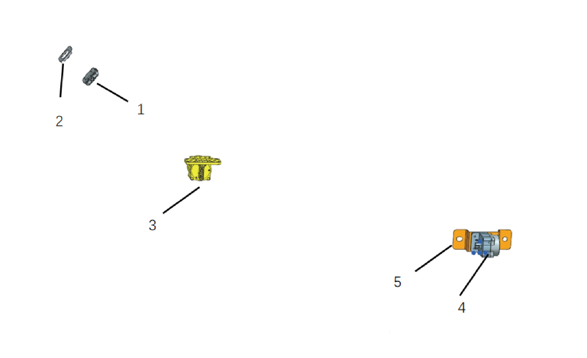
1.
4.
Reverse Buzzer
Light Rain Sensor
5.
2.
Reverse Buzzer Bracket
Brkt-Sunlight Rain Sensor
3.
Acoustic Vehicle Alerting System
7.3.3 System Schematic Diagram
7.3.3.1 Electrical Schematic Diagram
7.3.4 Diagnostic Information and Steps
7.3.4.1 Diagnosis Description
Before diagnosing faults in electrical accessory devices, it is important to understand and familiarize oneself with the working
principle of the electrical accessory device before starting the system diagnosis. This will help determine the correct steps for
fault diagnosis when a fault occurs, and more importantly, it will help determine the situation described by the customer belongs
to normal operation. Any fault diagnosis of electrical accessory devices should start with routine inspection, guiding maintenance
personnel to take the next logical step for fault diagnosis. Understanding and correctly using the diagnostic process can shorten
the diagnosis time and avoid misjudgment of faulty parts.
7.3.4.2 Routine Inspection
• Check for aftermarket devices that may affect the operation of the electrical accessory system, ensuring that these devices do
not affect the operation of the electrical accessory system.
• Inspect system components that are easily accessible or visible to make sure they are not visibly damaged or have conditions
that could cause failure.
7.3.4.3 Fault Symptom Table
Symptom
Suspected Faulty Project
Measures
1. The external sound module is
Clean up foreign objects.
covered by foreign objects
Reinstall the low-speed alarm module.
When the vehicle is driving at low
2. Interference with other components
Refer to Replacement Of Low-speed
speed, there is no sound or noise from
Alarm Module (AVAS)
the low-speed alarm module
Check for faults in the low-speed alarm
3. Low speed alarm module malfunction
module. Refer to Low Speed Alarm
Module Power Fault
7.3.4.4 DTC Confirmation
1.Connect the diagnostic instrument to the diagnostic interface, read and record the DTC, and then clear the DTC.
2. Restart the vehicle.
3. Read the fault code of the control system again to confirm the system has a fault code output.
– Yes:Diagnose based on the output fault code.
– No:Perform intermittent fault checks, refer to Inspection Of Intermittent Fault
7.3.4.5 List Of Diagnostic Trouble Codes (DTC)
AVAS
Fault Description
Exclusion Method
Fault Code
Voltage High
B111717
Refer to Low Speed Alarm Module
Power Fault
Voltage Low
B111716
TGW_TD_Time mesg lost
U019887
TGW_TD_Time mesg lost
U014087
Refer to Low Speed Alarm Module
CDC_BDCUSET mesg Lost
U015687
Communication Fault
VDC_CCVS LOST
U012287
U007D88
BCANFD2 BusOff
7.3.4.6 Low Speed Alarm Module Power Fault
1.DTC Monitoring Logic
Description
DTC Trigger Conditions
Faulty Part
DTC Code
Voltage High
Voltage > 33V, t > 2s
1. Main battery
B111717
2. Low voltage
charging system
3. Wiring harness
Voltage Low
Voltage < 18V, t > 2s
B111716
4. Low speed
alarm module
2.Circuit Diagram
Smart Junction
Box - Chassis
Battery
C4-16
AVAS-KL30 O416
25
I9_C_B
25
I9_B_C
Power KL30 O416
B31-6
Low speed alarm module
120Ω
B31-5
B31-4
B31-3
BCANFD2_H BH02b
BCANFD2_L BL02b
Ground Z11
BCANFD2_H BH02
BCANFD2_L BL02
G28
B48-38 B48-18
BDCU-4
3. Diagnostic Steps
Step 1:DTC Confirmation. Refer to DTC Confirmation
Step 2:Routine Inspection. Refer to Routine Inspection
Step 3:Check if there are any other module power fault codes besides the low-speed alarm module?
Check the main battery. Refer to Inspection Of The Main Battery
– Yes:
Check the low-voltage charging system. Refer to DCDC1 Low-voltage Charging System Fault
Next step
– No:
Step 4:Check the power and grounding harness of the low-speed alarm module.
Step 5:Rewrite the configuration code, reload the software, and upgrade the low-speed alarm module.
Step 6:Replace the low-speed alarm module. Refer to Replacement Of Low-speed Alarm Module (AVAS)
Step 7:Clear and confirm DTC.
7.3.4.7 Low Speed Alarm Module Communication Fault
1.DTC Monitoring Logic
Description
DTC Trigger Conditions
Faulty Part
DTC Code
TGW_TD_Time mesg
10 cycle lost
U019887
lost
BDCU_OELight mesg
10 cycle lost
U014087
1.Wiring harness
lost
2. Low speed
CDC_BDCUSET
10 cycle lost
U015687
alarm module
mesg Lost
10 cycle lost
VDC_CCVS LOST
U012287
Err cycle more 255
U007D88
BCANFD2 BusOff
2.Circuit Diagram
Smart Junction
Box - Chassis
Battery
C4-16
AVAS-KL30 O416
25
I9_C_B
25
I9_B_C
Power KL30 O416
B31-6
Low speed alarm module
120Ω
B31-5
B31-4
B31-3
BCANFD2_H BH02b
BCANFD2_L BL02b
Ground Z11
BCANFD2_H BH02
BCANFD2_L BL02
G28
B48-38 B48-18
BDCU-4
3. Diagnostic Steps
Step 1:DTC Confirmation. Refer to DTC Confirmation
Step 2:Routine Inspection. Refer to Routine Inspection
Step 3:Check the BCANFD1 bus communication harness. Refer to Inspection Of BCAND1 Bus Network Integrity
Step 4:Rewrite the configuration code, reload the software, and upgrade the low-speed alarm module.
Step 5:Replace the low-speed alarm module. Refer to Replacement Of Low-speed Alarm Module (AVAS)
Step 6:Clear and confirm DTC.
7.3.5 Dismantling and Installation
7.3.5.1 Replacement of RLS
Removal Procedures
1
Open the door.
2
Open the front flip cover plate.
3
Disconnect the battery negative cable.
caution
power down the high-voltage system before
disconnecting the negative pole of the storage
battery.
4
Remove the front camera trim cover assembly.
5
Disconnect 1 harness connector of the RLS.
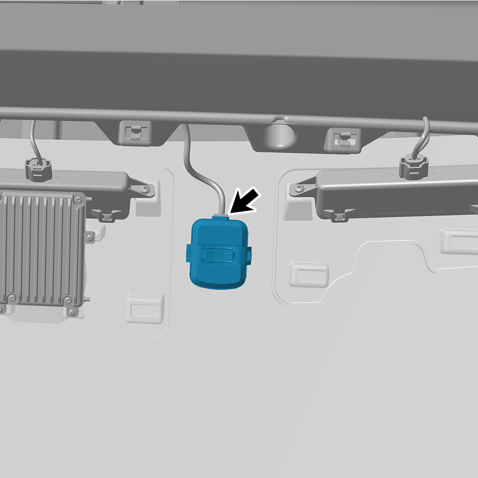
6
Remove the RLS.
Installation Procedures
1
Move the RLS to the mounting position.
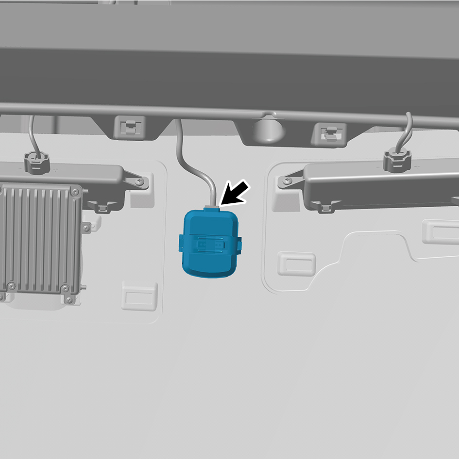
2
Connect 1 harness connector of the RLS.
caution
1.The harness is firmly connected following the
principal of "insert until a click is heard for
confirmation".
2.Note that the installation surface should be clean,
and no foreign substances or stains are allowed.
3
Install the front camera trim cover assembly.
4
Connect the battery negative cable.
5
Close the front flip cover plate.
6
Close the door.
7.3.5.2 Replacement of AVAS
Removal Procedures
1
Open the door.
2
Open the front flip cover plate.
3
Disconnect the battery negative cable.
caution
power down the high-voltage system before
disconnecting the negative pole of the storage
battery.
4
Remove the lamp (upper).
5
Remove the lamp (lower).
6
Remove the boarding step body assembly.
7
Remove the lower wheel housing connecting bracket.
8
Remove the boarding step tubular beam.
9
Disconnect 1 harness connector of the AVAS.
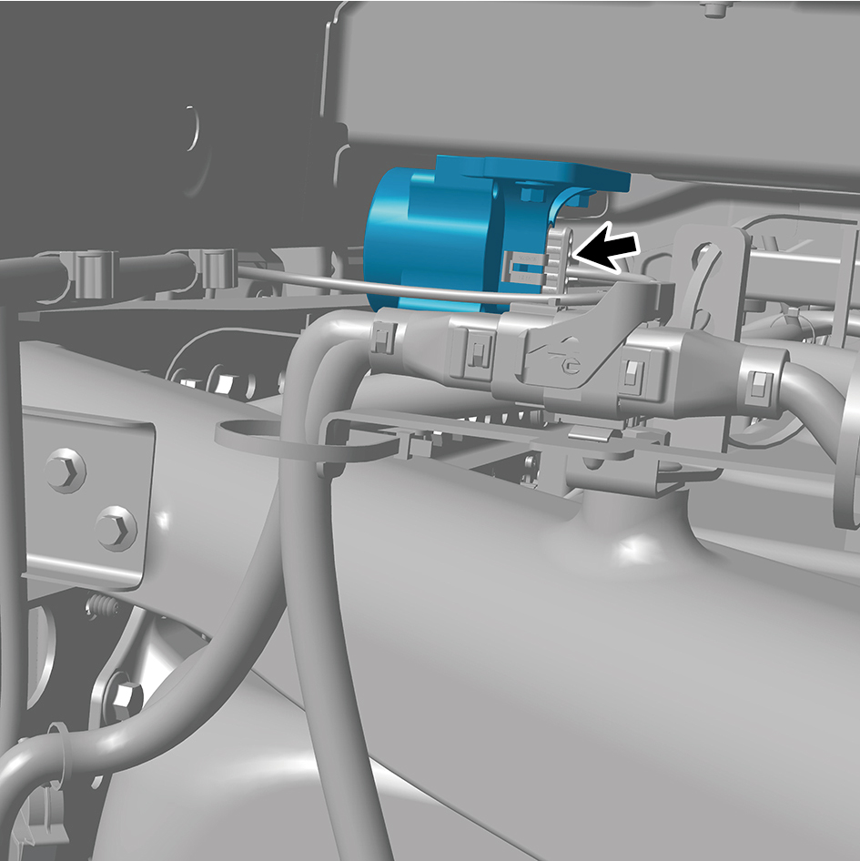
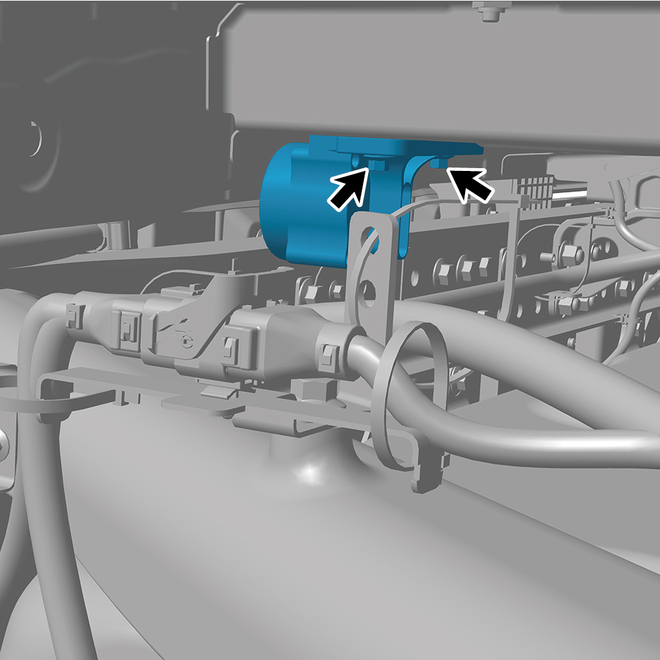
10
Remove 2 fixing bolts of the AVAS.
11
Remove the AVAS.
Installation Procedures
1
Move the AVAS to the mounting position.
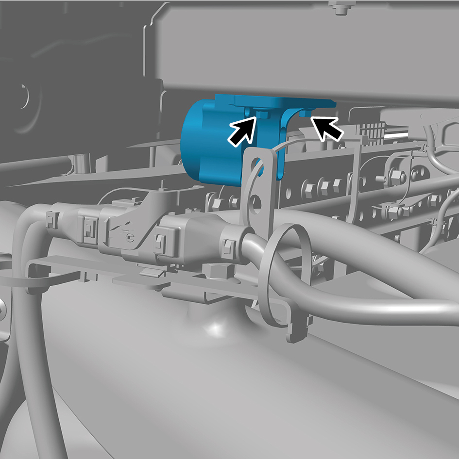
2
Install 2 fixing bolts of the AVAS.
Torque: (18 +/- 2) ft lbs
3
Connect 1 harness connector of the AVAS.
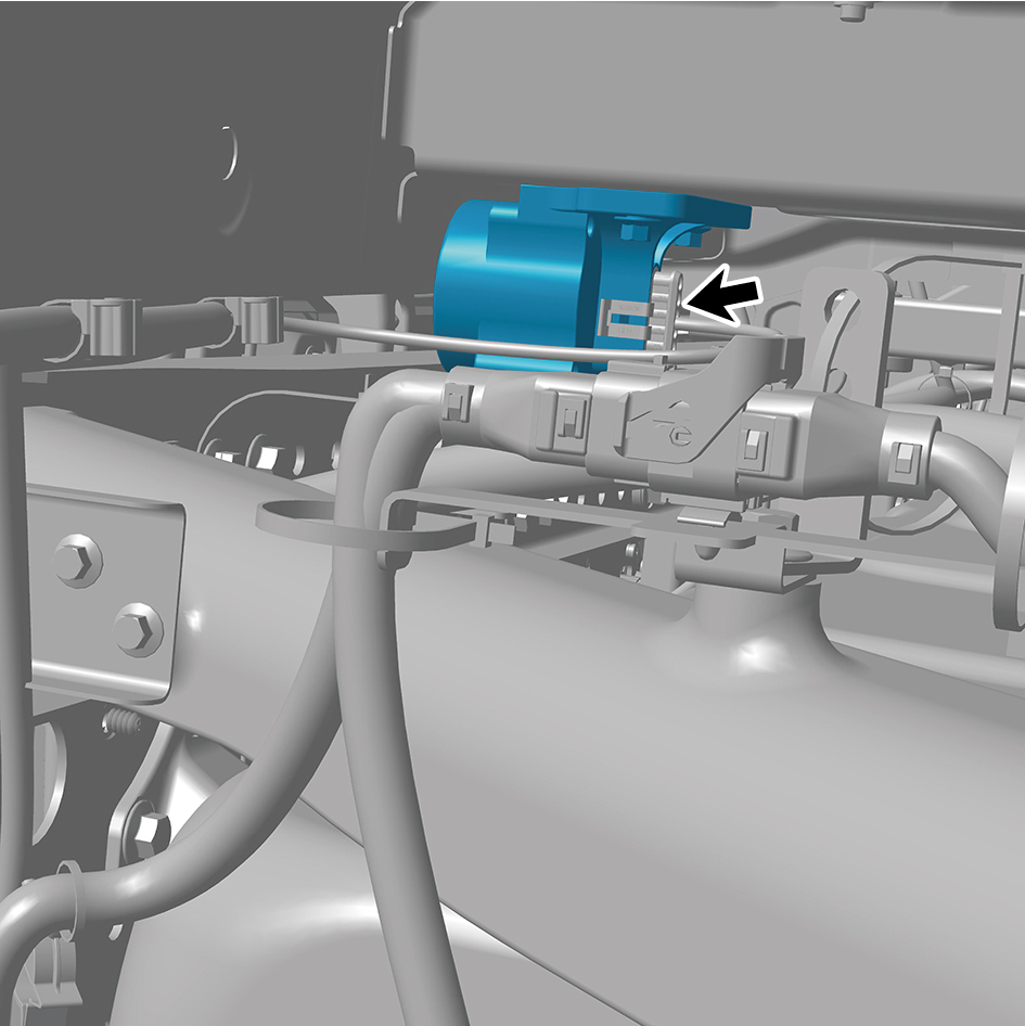
caution
The harness is firmly connected following the
principal of "insert until a click is heard for
confirmation".
4
Install the boarding step tubular beam.
5
Install the lower wheel housing connecting bracket.
6
Install the boarding step body assembly.
7
Install the lamp (lower).
8
Install the lamp (upper).
9
Connect the battery negative cable.
10
Close the front flip cover plate.
11
Close the door.
7.3.5.3 Replacement of The Reverse Buzzer
Removal procedures
1
Open the door.
2
Open the front flip cover plate.
3
Disconnect the battery negative cable.
caution
power down the high-voltage system before
disconnecting the negative pole of the storage
battery.
4
Disconnect 1 wire harness connector of the reverse
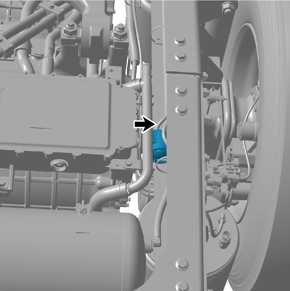
buzzer.
5
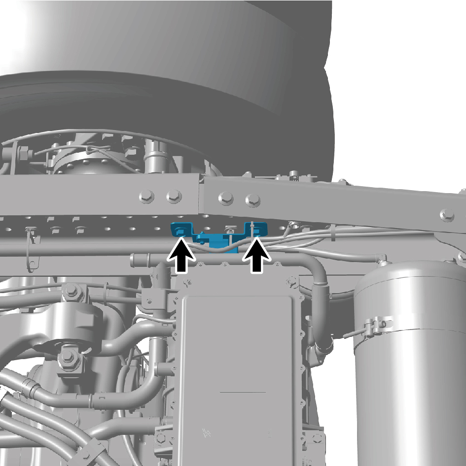
Remove the 2 fixing bolts of the reverse buzzer.
6
Remove the reverse buzzer.
Installation procedures
1
Move the reverse buzzer to the mounting position.

2
Install the 2 fixing bolts of the reverse buzzer.
3
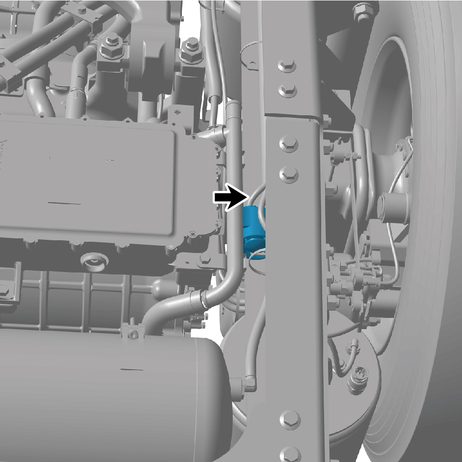
Connect 1 wire harness connector of the reverse buzzer.
caution
The harness is firmly connected following the
principal of "insert until a click is heard for
confirmation".
4
Connect the battery negative cable.
5
Close the front flip cover plate.
6
Close the door.