← Back to Contents
7 Automotive Electrical Appliances / 7.2 Vehicle Control Unit (VCU) Device | PDF pages 1142-1261
7.2 Vehicle Control Unit (VCU) Device
7.2 Vehicle Control Unit (VCU) Device
7.2.1 Specifications
7.2.1.1 Fastener Specifications
Range Of Torque
Fastener Specifications
Specifications
Foot Pounds of Torque (ft lbs)
The fixing bolt connecting the power
domain controller bracket to the battery
(6.5 +/- .75) ft lbs
M6
pressure plate 2
The fixing bolt connecting the power
domain controller bracket to the battery
(6.5 +/- .75) ft lbs
M6
pressure plate 3
The fixing bolts connecting the bracket
of the power domain controller to the
(11 +/- 1.5) ft lbs
M6
power domain controller assembly
7.2.2 Decomposition Diagram
7.2.2.1 Decomposition Diagram
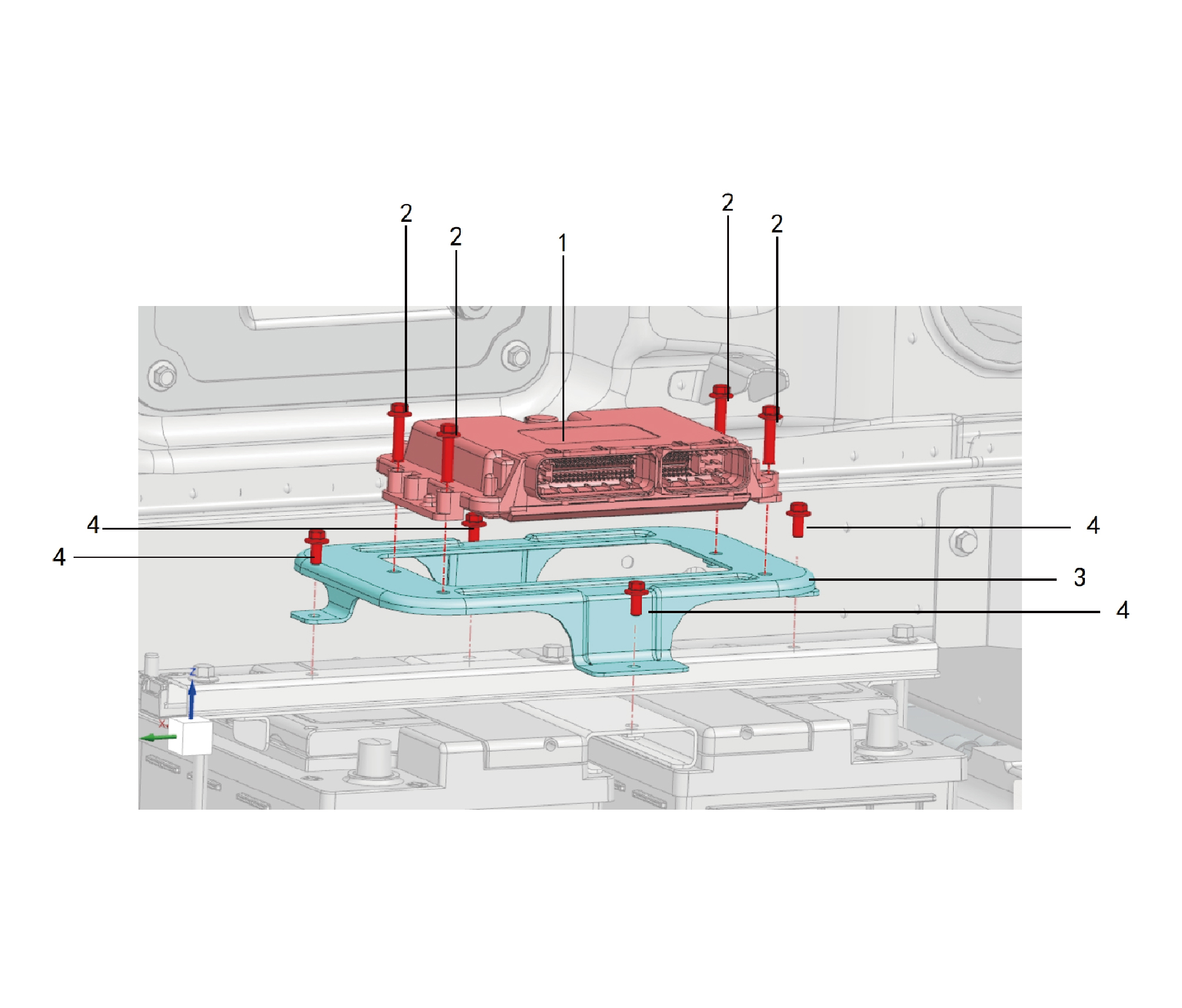
1.
3.
Vehicle Domain Controller
Vehicle Controller Assy Bracket
2.
Hexagon Flange Bolt
4.
Hexagon Flange Bolt
7.2.3 System Schematic Diagram
7.2.3.1 Electrical Schematic Diagram
Vehicle domain controller(VDC)
EVCC
7.2.4 Diagnostic Information and Steps
7.2.4.1 Diagnosis Description
Before diagnosing the fault of the vehicle controller device, understand and be familiar with the working principle of the vehicle
controller device, and then start system diagnosis. This will help determine the correct fault diagnosis steps when a fault occurs.
More importantly, this Helps determine the situation described by the customer is normal operation. Any fault diagnosis of the
vehicle controller device should start with Routine Inspection to guide the maintenance personnel to take the next logical step for
fault diagnosis. Understanding and correctly using the diagnostic process can shorten diagnosis time and avoid misjudgment of
faulty parts.
7.2.4.2 Routine Inspection
• Check after-sales installation devices that may affect the operation of the vehicle controller device system, and ensure that
these devices cannot affect the operation of the vehicle controller device system.
• Inspect system components that are easily accessible or visible to make sure they are not visibly damaged or have conditions
that could cause failure.
7.2.4.3 DTC Confirmation
1.Connect the diagnostic instrument to the diagnostic interface, read and record the DTC, and then clear the DTC.
2. Restart the vehicle.
3. Read the fault code of the control system again to confirm whether the system has a fault code output.
– Yes:Diagnose based on the output fault code.
– No:Perform intermittent fault checks, refer to Inspection Of Intermittent Fault
7.2.4.4 List Of Diagnostic Trouble Codes (DTC)
VDC
Fault Description
Troubleshooting
Fault Code
P10F752
Lost Communication With WPTC1/2
P10F852
Lost Communication With BLR1/2
U019887
Lost Communication With T-Box
U014087
Lost Communication With BDCU
Lost Communication With SJB_UP
U01A087
U019987
Lost Communication With DCM
Lost Communication With SJB_UN
U01A187
U015687
Lost Communication With CDCU
U017487
Lost Communication With CMU01
U017587
Lost Communication With CMU02
Refer to VDC Communication Fault
U017687
Lost Communication With CMU03
U017787
Lost Communication With CMU04
U017887
Lost Communication With CMU05
U017987
Lost Communication With CMU06
U017A87
Lost Communication With PDU1
U017B87
Lost Communication With PDU2
U017C87
Lost Communication With PDU3
U012A87
Lost Communication With MCU1
U012B87
Lost Communication With MCU2
U012C87
Lost Communication With MCU3
Fault Description
Troubleshooting
Fault Code
U012D87
Lost Communication With MCU4
U010187
Lost Communication With TCU1
U010287
Lost Communication With TCU2
U01B387
Lost Communication With GSM
U012187
Lost Communication With EBS
U013287
Lost Communication With ECAS
U012887
Lost Communication With EPB
PCAN2_Busoff
U008C88
PCAN3_Busoff
U008D88
PCAN4_Busoff
U008E88
ChargrCAN_Busoff
U008B88
CANFD7_Busoff
U007988
CANFD10_Busoff
U008088
HTP_P Sensor 1, short circuit
P101010
HTP_P Sensor 1, open circuit
P101110
HTP_P Sensor 2, short circuit
P101210
HTP_P Sensor 2, open circuit
P101310
LTP_P Sensor 1, short circuit
P101410
LTP_P Sensor 1, open circuit
P101510
LTP_P Sensor 2, short circuit
P101610
LTP_P Sensor 2, open circuit
P101710
Refer to VDC Internal Fault
HPT_T Sensor 1, open circuit
P101810
HPT_T Sensor 1, short circuit
P101910
HPT_T Sensor 2, open circuit
P101A10
HPT_T Sensor 2, short circuit
P101B10
LPT_T Sensor 1, open circuit
P101C10
LPT_T Sensor 1, short circuit
P101D10
LPT_T Sensor 2, open circuit
P101E10
LPT_T Sensor 2, short circuit
P101F10
AccPed 1, short circuit
P102C10
AccPed 2, short circuit
P102D10
AccPed 1, open circuit
P102E10
AccPed 2, open circuit
P102F10
Refer to Accelerator Pedal Fault
The calibration values of the two
P103010
accelerator pedals do not match
Both accelerator pedals malfunction
P103110
simultaneously
The motor liquid level sensor is short of
Refer to Motor Coolant Level Sensor
P103910
liquid
Fault
Fault Description
Troubleshooting
Fault Code
The battery liquid level sensor is short of
Refer to Battery Coolant Level Sensor
P103A10
liquid
Fault
Refrigerant shortage in the unitt
P103D10
QCM_BatOverTptFaultA
P10D340
QCM_BatOverTptFaultB
P100D40
CMU1 Thermal runaway fault
P108130
CMU2 Thermal runaway fault
P108230
Refer to Battery Thermal Runaway F
ault
CMU3 Thermal runaway fault
P108330
CMU4 Thermal runaway fault
P108430
CMU5 Thermal runaway fault
P108530
CMU6 Thermal runaway fault
P108630
Hard wire detection thermal runaway
P108730
fault
ExhT Sensor 1, short circuit the power
P102810
Refer to Left Exhaust Temperature
supply
Sensor Fault
ExhT Sensor 1, short circuit to ground
P102910
ExhT Sensor 2, short circuit the power
P102A10
Refer to Right Exhaust Temperature
supply
Sensor Fault
ExhT Sensor 2, short circuit to ground
P102B10
Abnormal rotation speed detection of
P10F340
MCU1
Abnormal rotation speed detection of
P10F440
MCU2
Abnormal rotation speed detection of
Refer to VDC Reports MCU Internal
P10F540
MCU3
Fault
Abnormal rotation speed detection of
P10F640
MCU4
NormRdyFltChkFailr_St
P10C040
P10E563
MCU failure
CMUx negative pole relay sticking
P10C630
together
QCM_BSTSocTarA
P10CB40
QCM_BSTTotalVTarA
P10CC40
QCM_BSTCSTEnA
P10CE40
Refer to VDC Reports Internal Fault In
QCM_HVRealyFaultA
P10D440
CMU
QCM_BSTSocTarB
P10D940
QCM_BSTTotalVTarB
P10DA40
QCM_BSTCSTEnB
P10DC40
QCM_HVRealyFaultB
P100E40
Fault Description
Troubleshooting
Fault Code
CMU1 total voltage is too high
P107430
CMU1 total voltage is too low
P107530
CMU2 total voltage is too high
P107630
CMU2 total voltage is too low
P107730
CMU3 total voltage is too high
P107830
CMU3 total voltage is too low
P107930
CMU4 total voltage is too high
P107A30
CMU4 total voltage is too low
P107B30
CMU5 total voltage is too high
P107C30
CMU5 total voltage is too low
P107D30
CMU6 total voltage is too high
P107E30
CMU6 total voltage is too low
P107F30
The voltage difference between
P108030
packages is too high
Battery failure
P10E061
QCM_BSTSingleVTarA
P10CD40
QCM_BSTSingleVTarB
P10DB40
CMU1 Cell overvoltage
P105030
CMU1 Cell undervoltage
P105130
CMU2 Cell overvoltage
P105430
CMU2 Cell undervoltage
P105530
CMU3 Cell overvoltage
P105830
CMU3 Cell undervoltage
P105930
CMU4 Cell overvoltage
P105C30
CMU4 Cell undervoltage
P105D30
Refer to VDC Reports Abnormal
Voltage Of CMU Unit
CMU5 Cell overvoltage
P106030
CMU5 Cell undervoltage
P106130
CMU6 Cell overvoltage
P106430
CMU6 Cell undervoltage
P106530
CMU1 Cell volt difference is large
P106830
CMU2 Cell volt difference is large
P106930
CMU3 Cell volt difference is large
P106A30
CMU4 Cell volt difference is large
P106B30
CMU5 Cell volt difference is large
P106C30
CMU6 Cell volt difference is large
P106D30
P10AD40
TCU1 ratio verification error
Refer to VDC Reports TCU Internal
Fault
P10AE40
TCU4 ratio verification error
Fault Description
Troubleshooting
Fault Code
P10FB40
TCU2 ratio verification error
P10FC40
TCU3 ratio verification error
P10E663
TCU failure
P104E53
TCU4 Communication failure
P10F953
TCU2 Communication failure
Refer to VDC Reports TCU
Communication Fault
P10FA53
TCU3 Communication failure
P104D53
TCU1 Communication failure
P10B051
CMUAll Communication failure
PDU_PDU failure
P10E162
Refer to VDC Reports Internal Fault Of
PDU_DCAC failure
PDU
P10E262
PDU_DCDC failure
P10E362
P10B110
AGM1 feedback failure
P10B210
AGM2 feedback failure
Refer to Active Grille Shutter Fault
Grid Communication Fault - Left
P103B10
Grid Communication Failure - Right
P103C10
QCM_InsulationFaultA
P10CF40
QCM_InsulationFaultB
P10DD40
Refer to Insulation Fault
P109C30
Insulation fault LvC
P109D30
Insulation fault LvB
P109E30
Insulation fault LvA
The rate at which the working pressure
P10AC40
of the air pump rises is slow.
Refer to Air Compressor Fault
NormRdy_AirPChkFailr_St
P10C140
Abnormal heating during low-
P10C740
temperature charging
Abnormal cooling during high-
P10C840
Refer to Thermal Management System
temperature charging
Fault
Abnormal cooling during high-
P10CA40
temperature discharge
thermal management system failure
P10E462
Refer to CC2 Signal F
ailure
Charging Wake-up Abnormality
P103E10
Battery fan failure
P103410
Refer to Battery Fan Fault
Three-way valve A malfunction
P103510
Refer to Three Valve
Three-way valve A malfunction
P103510
Failure
Refer to Three Valve
Three-way valve B failure
P103810
Failure
Fault Description
Troubleshooting
Fault Code
Battery pump failure
P103710
Refer to Battery Water Pump Fault
Three-way valve B failure
P103810
FCT Sensor 1, open circuit
P102010
FCT Sensor 1, short circuit
P102110
FCT Sensor 2, open circuit
P102210
FCT Sensor 2, short circuit
P102310
Refer to Fast Charging Interface
Temperature Detection Signal Fault
FCT Sensor 3, open circuit
P102410
FCT Sensor 3, short circuit
P102510
FCT Sensor 4, open circuit
P102610
FCT Sensor 4, short circuit
P102710
Fast charge temperature check 1
P108830
Overtemperature LvA
Fast charge temperature check 2
P108930
Overtemperature LvA
Fast charge temperature check 3
P108A30
Overtemperature LvA
Fast charge temperature check 4
P108B30
Overtemperature LvA
Fast charge temperature check 1
P108C30
Overtemperature LvB
Fast charge temperature check 2
P108D30
Overtemperature LvB
Fast charge temperature check 3
P108E30
Overtemperature LvB
Fast charge temperature check 4
P108F30
Overtemperature LvB
Brake signal verification does not match
P103210
Brake pressure sensor 1 is faulty
P10B310
Refer to VDC Reports EBS Fault
Brake pressure sensor 2 is faulty
P10B410
Brake pressure monitoring
P10AB40
Refer to VDC IBS TCU Communication
P103F10
IBS communication failure
Fault
Compressor 1_TSH_Tsat_flt
P10B510
Compressor 2_TSH_Tsat_flt
P10C910
Refer to Battery Compressor Fault
P100A52
BLR1 Communication failure
P100B52
BLR2 Communication failure
QCM_OutputConOverTptFaultA
P10D040
Refer to Overheating During Charging
QCM_BMSOverTptFaultA
P10D140
QCM_ChrConFaultA
P10D240
Fault Description
Troubleshooting
Fault Code
QCM_OutputConOverTptFaultB
P10DE40
QCM_BMSOverTptFaultB
P10DF40
QCM_ChrConFaultB
P100C40
QCM_DetectionPoint2FaultA
P10D540
QCM_OtherFaultA
P10D640
QCM_BatCurOverFaultA
P10D740
QCM_BatVAbnorFaultA
P10D840
Refer to Charging Status Abnormal
QCM_DetectionPoint2FaultB
P100F40
QCM_OtherFaultB
P10F040
QCM_BatCurOverFaultB
P10F140
QCM_BatVAbnorFaultB
P10F240
VDC detects high-voltage interlock
Refer to VDC High-Voltage Interlock
P10A930
failure
Failure
FAirLoss_Flt_flg
P10C440
Refer to Abnormal Air Leakage In The
Braking System
RAirLoss_Flt_flg
P10C540
Low voltage power supply undervoltage
P100000
LvA
Low voltage power supply undervoltage
P100100
LvB
Low-voltage power supply overvoltage
P100200
Refer to VDC Power Fault
LvA
Low-voltage power supply overvoltage
P100300
LvB
DCDC1 output undervoltage
P100402
DCDC1 output overvoltage
P100502
DCDC2 output undervoltage
P100602
Refer to DCDC2 Voltage Output Fault
DCDC2 output overvoltage
P100702
P103310
Motor fan failure
Refer to Motor Fan Fault
Motor pump failure
Refer to Motor And Water Pump Fault
P103610
P104051
CMU1 Communication failure
P104151
CMU2 Communication failure
P104251
CMU3 Communication failure
Refer to VDC Reports CMU
Communication Fault
P104351
CMU4 Communication failure
P104451
CMU5 Communication failure
P104551
CMU6 Communication failure
P104652
PDU_PDU Communication failure
Refer to VDC Reports PDU
P104752
PDU_DCAC Communication failure
Communication Fault
P104852
PDU_DCDC Communication failure
P104953
MCU1 Communication failure
Refer to VDC Reports MCU
Communication Fault
P104A53
MCU2 Communication failure
Fault Description
Troubleshooting
Fault Code
P104B53
MCU3 Communication failure
P104C53
MCU4 Communication failure
Refer to VDC Reports GSM
P104F53
GSM Communication failure
Communication Fault
Refer to Left Battery Water Heater Fault
P100852
WPTC1 Communication failure
Refer to Fault In The Right Water Heater
P100952
WPTC2 Communication failure
Of The Battery
U120587
LIN flt status
Refer to VDC LIN Communication Fault
CMU1 Cell overtemp
P105230
CMU1 Cell undertemp
P105330
CMU2 Cell overtemp
P105630
CMU2 Cell undertemp
P105730
CMU3 Cell overtemp
P105A30
CMU3 Cell undertemp
P105B30
CMU4 Cell overtemp
P105E30
CMU4 Cell undertemp
P105F30
CMU5 Cell overtemp
P106230
CMU5 Cell undertemp
Refer to VDC Reports Abnormal CMU
P106330
Temperature
CMU6 Cell overtemp
P106630
CMU6 Cell undertemp
P106730
CMU1 Cell temp difference is large
P106E30
CMU2 Cell temp difference is large
P106F30
CMU3 Cell temp difference is large
P107030
CMU4 Cell temp difference is large
P107130
CMU5 Cell temp difference is large
P107230
CMU6 Cell temp difference is large
P107330
The temperature difference between
P10AA30
packages is too high
CMU1 Charge overcurrent LvB
P109030
CMU1 Charge overcurrent LvA
P109130
CMU2 Charge overcurrent LvB
P109230
CMU2 Charge overcurrent LvA
P109330
CMU3 Charge overcurrent LvB
P109430
Refer to VDC Reports CMU High
Voltage Circuit Fault
CMU3 Charge overcurrent LvA
P109530
CMU4 Charge overcurrent LvB
P109630
CMU4 Charge overcurrent LvA
P109730
CMU5 Charge overcurrent LvB
P109830
CMU5 Charge overcurrent LvA
P109930
Fault Description
Troubleshooting
Fault Code
CMU6 Charge overcurrent LvB
P109A30
CMU6 Charge overcurrent LvA
P109B30
CMU1 High voltage interlock fault
P109F30
CMU2 High voltage interlock fault
P10A030
CMU3 High voltage interlock fault
P10A130
Refer to VDC Reports CMU High
Voltage Interlock Fault
CMU4 High voltage interlock fault
P10A230
CMU5 High voltage interlock fault
P10A330
CMU6 High voltage interlock fault
P10A430
MCU1 High voltage interlock fault
P10A530
MCU2 High voltage interlock fault
P10A630
Refer to VDC Reports MCU High
Voltage Interlock Fault
MCU3 High voltage interlock fault
P10A730
MCU4 High voltage interlock fault
P10A830
NormupBnRlyChkFailr_St
P10AF40
Refer to CMU Wake-up Signal Fault
ChUpBnRlyChkFailr_St
P10BA40
NormRdy_Gear_ChkFailr_St
P10C240
Refer to VDC Reports GSM Internal
Fault
P10E763
GSM failure
NormRdy_Escl_ChkFailr_St
P10C340
Refer to ESCL Fault
P10E863
IBS failure
Refer to IBS Fault
7.2.4.5 Action Test List
By reading the "action test" on the fault diagnosis instrument, the working status of the relays and actuators controlled by VDC
can be checked without disassembling any parts. Before performing relevant fault diagnosis on the control system, performing an
action test is a prerequisite for troubleshooting, which can shorten the troubleshooting time.
Note
The data under normal conditions are listed in the table below for reference only. Never rely solely on these
reference values to determine whether a part has failed. Usually, a normal working vehicle can be compared with
the diagnosed vehicle in the same state to determine whether the diagnosed vehicle data is normal in the current
state.
a.Perform vehicle power-on operation.
b.Connect the diagnostic tool.
c.Select "VDC"/"Action Test".
d.Refer to the table below for proactive testing.
Diagnostic Tool Display
Diagnosis Description
Span Of Control
Test Parts
Items
According to the instructions of the
Drive water pump control
Motor water pump
diagnostic instrument, control the motor
Turn on/off
and water pump to turn on/off
Control the motor fan to turn on/off
Drive fan control
Motor fan
Turn on/off
according to the diagnostic instrument
instructions
Diagnostic Tool Display
Span Of Control
Diagnosis Description
Test Parts
Items
According to the instructions of the
Battery water pump 1
Battery water pump 1
diagnostic instrument, control the battery
Turn on/off
control
water pump 1 to turn on/off
According to the instructions of the
Battery water pump 2
Battery water pump 2
diagnostic instrument, control the battery
Turn on/off
control
water pump 2 to turn on/off
According to the instructions of the
Battery fan 1 control
Battery fan 1
diagnostic tool, control the battery fan 1 to
Turn on/off
turn on/off
According to the instructions of the
Battery fan 2 control
Battery fan 2
diagnostic tool, control the battery fan 2 to
Turn on/off
turn on/off
7.2.4.6 VDC Power Fault
1.DTC Monitoring Logic
Description
DTC Trigger Conditions
Faulty Part
DTC Code
Low voltage power
Power on, The low-voltage power supply is less than or
P100000
supply undervoltage
equal to 18V for 10s
LvA
Low voltage power
Power on, The low-voltage power supply is less than or
P100100
supply undervoltage
equal to 10V for 2s
LvB
1. Main battery
Low-voltage power
Power on, The low-voltage power supply is greater than
2. Low voltage
P100200
supply overvoltage
or equal to 32V for 10s
charging system
LvA
3. Wiring harness
Low-voltage power
Power on, The low-voltage power supply is greater than
4.VDC
P100300
supply overvoltage
or equal to 35V for 2s
LvB
DCDC1 output
HV Satus, The DCDC1 function takes effect, DCDC1
P100402
undervoltage
output voltage is less than or equal to 23V for 10s
DCDC1 output
HV Satus, The DCDC1 function takes effect, DCDC1
P100502
overvoltage
output voltage is greater than or equal to 32V for 10s
2.Circuit Diagram
3. Diagnostic Steps
Step 1:DTC Confirmation. Refer to DTC Confirmation
Step 2:Routine Inspection. Refer to Routine Inspection
Step 3:Check there are other module power fault codes besides VDC?
Check the main battery. Refer to Inspection Of The Main Battery
– Yes:
Check the low-voltage charging system. Refer to DCDC1 Low-voltage Charging System Fault
Next step
– No:
Step 4:Check the VDC power supply and grounding harness.
Step 5:VDC rewrites the configuration code, software reloads, and upgrades.
Step 6:Replace VDC. Refer to Replacement Of Vehicle Domain Controller Assembly
Step 7:Clear and confirm DTC.
7.2.4.7 VDC Communication Fault
1.DTC Monitoring Logic
Description
DTC Trigger Conditions
Faulty Part
DTC Code
Lost Communication
KL15 valid, 0x18032779x/0x18032760x lost, last for 5s
P10F752
With WPTC1/2
Lost Communication
KL15 valid, 0x1802277Ax/0x1802277Bx lost, last for 5s
P10F852
With BLR1/2
Lost Communication
KL15 valid, 0x18FF18FBx lost, last for 2s
U019887
With T-Box
Lost Communication
KL15 valid, 0x18FF1921x lost, last for 1s
U014087
With BDCU
Lost Communication
KL15 valid, 0x18FF3354x lost, last for 1s
U01A087
With SJB_UP
Lost Communication
KL15 valid, 0x18FDA54Fx lost, last for 1s
U019987
With DCM
Lost Communication
KL15 valid, 0x18FF2359x lost, last for 1s
U01A187
With SJB_UN
1.Wiring harness
Lost Communication
KL15 valid, 0x18FF1241x lost, last for 2s
U015687
2.VDC
With CDCU
Lost Communication
KL15 valid, 0x18082768x lost, last for 1s
U017487
With CMU01
Lost Communication
KL15 valid, 0x18082769x lost, last for 1s
U017587
With CMU02
Lost Communication
KL15 valid, 0x1808276Ax lost, last for 1s
U017687
With CMU03
Lost Communication
KL15 valid, 0x1808276Bx lost, last for 1s
U017787
With CMU04
Lost Communication
KL15 valid, 0x1808276Cx lost, last for 1s
U017887
With CMU05
Lost Communication
KL15 valid, 0x1808276Dx lost, last for 1s
U017987
With CMU06
Lost Communication
KL15 valid, 0x18012778x lost, last for 1s
U017A87
With PDU1
Description
DTC Trigger Conditions
Faulty Part
DTC Code
Lost Communication
KL15 valid, 0x1804276Ex lost, last for 1s
U017B87
With PDU2
Lost Communication
KL15 valid, 0x1801276Fx lost, last for 1s
U017C87
With PDU3
Lost Communication
KL15 valid, 0x18012774x lost, last for 0.5s
U012A87
With MCU1
Lost Communication
KL15 valid, 0x18012775x lost, last for 0.5s
U012B87
With MCU2
Lost Communication
KL15 valid, 0x18012776x lost, last for 0.5s
U012C87
With MCU3
Lost Communication
KL15 valid, 0x18012777x lost, last for 0.5s
U012D87
With MCU4
Lost Communication
KL15 valid, 0x18012703x lost, last for 0.5s
U010187
With TCU1
Lost Communication
KL15 valid, 0x18012703x lost, last for 0.5s
U010287
With TCU2
Lost Communication
KL15 valid, 0x0C010305x lost, last for 0.5s
U01B387
With GSM
Lost Communication
KL15 valid, 0x18F0010Bx lost, last for 1s
U012187
With EBS
Lost Communication
KL15 valid, 0x18FECA2Fx lost, last for 5s
U013287
With ECAS
Lost Communication
KL15 valid, 0x18FE1250x lost, last for 1s
U012887
With EPB
PCAN2_Busoff
U008C88
Enter busoff
PCAN3_Busoff
U008D88
Enter busoff
PCAN4_Busoff
U008E88
Enter busoff
ChargrCAN_Busoff
U008B88
Enter busoff
CANFD7_Busoff
U007988
Enter busoff
CANFD10_Busoff
U008088
Enter busoff
2.Circuit Diagram
VDC
120Ω
C94-10
C94-9
Battery PCAN2-L PL02
Battery PCAN2-H PH02
Battery PCAN2-L PL02
Battery PCAN2-L PL02
Battery PCAN2-H PH02
Battery PCAN2-H PH02
7
2
23
24
I_C_LP
I_C_LP
I3_C_B
I3_C_B
7
2
23
24
I1_LP_C
I1_LP_C
I3_B_C
I3_B_C
Battery PCAN2-L PL02
Battery PCAN2-L PL02
Battery PCAN2-H PH02
Battery PCAN2-H PH02
Battery PCAN
Battery PCAN
3. Diagnostic Steps
Step 1:DTC Confirmation. Refer to DTC Confirmation
Step 2:Routine Inspection. Refer to Routine Inspection
Step 3:Check the PCAN1 bus communication harness. Refer to Inspection Of PCAN1 Bus Network Integrity
Step 4:Check the PCAN2 bus communication harness. Refer to Inspection Of PCAN2 Bus Network Integrity
Step 5:Check the PCAN3 bus communication harness. Refer to Inspection Of PCAN3 Bus Network Integrity
Step 6:Check the PCAN4 bus communication harness. Refer to Inspection Of PCAN4 Bus Network Integrity
Step 7:Check the CANFD7 bus communication harness. Refer to Inspection Of CANFD7 Bus Network Integrity
Step 8:VDC rewrites the configuration code, software reloads, and upgrades.
Step 9:Replace the VDC. Refer to Replacement Of Vehicle Domain Controller Assembly
Step 10:Clear and confirm DTC.
7.2.4.8 VDC Internal Fault
1.DTC Monitoring Logic
Description
DTC Trigger Conditions
Faulty Part
DTC Code
Power on, The AD value is greater than or equal to
HTP_P Sensor 1,
P101010
4120 for 10s
short circuit
HTP_P Sensor 1,
Power on, The AD value is less than or equal to 20 for
P101110
open circuit
10s
Power on, The AD value is greater than or equal to
HTP_P Sensor 2,
P101210
4120 for 10s
short circuit
HTP_P Sensor 2,
Power on, The AD value is less than or equal to 20 for
P101310
open circuit
10s
Power on, The AD value is greater than or equal to
LTP_P Sensor 1, short
P101410
4120 for 10s
circuit
Power on, The AD value is less than or equal to 20 for
LTP_P Sensor 1, open
P101510
10s
circuit
Power on, The AD value is greater than or equal to
LTP_P Sensor 2, short
P101610
4120 for 10s
circuit
Power on, The AD value is less than or equal to 20 for
LTP_P Sensor 2, open
1.VDC
P101710
10s
circuit
Power on, The AD value is greater than or equal to
HPT_T Sensor 1, open
P101810
4100 for 10s
circuit
Power on, The AD value is less than or equal to 40 for
HPT_T Sensor 1, short
P101910
10s
circuit
Power on, The AD value is greater than or equal to
HPT_T Sensor 2, open
P101A10
4100 for 10s
circuit
Power on, The AD value is less than or equal to 40 for
HPT_T Sensor 2, short
P101B10
10s
circuit
Power on, The AD value is greater than or equal to
LPT_T Sensor 1, open
P101C10
4100 for 10s
circuit
Power on, The AD value is less than or equal to 40 for
LPT_T Sensor 1, short
P101D10
10s
circuit
Power on, The AD value is greater than or equal to
LPT_T Sensor 2, open
P101E10
4100 for 10s
circuit
Description
DTC Trigger Conditions
Faulty Part
DTC Code
Power on, The AD value is less than or equal to 40 for
LPT_T Sensor 2, short
P101F10
10s
circuit
2. Diagnostic Steps
Step 1:DTC Confirmation. Refer to DTC Confirmation
Step 2:Routine Inspection. Refer to Routine Inspection
Step 3:VDC rewrites the configuration code, software reloads, and upgrades.
Step 4:Replace the VDC. Refer to Replacement Of Vehicle Domain Controller Assembly
Step 5:Clear and confirm DTC.
7.2.4.9 Accelerator Pedal Fault
1.DTC Monitoring Logic
Description
DTC Trigger Conditions
Faulty Part
DTC Code
Power on, The AD value is greater than or equal to
AccPed 1, short circuit
P102C10
3250 for 10s
Power on, The AD value is greater than or equal to
AccPed 2, short circuit
P102D10
1650 for 10s
Power on, The AD value is less than or equal to 550 for
AccPed 1, open circuit
P102E10
10s
Power on, The AD value is less than or equal to 250 for
1.Wiring harness
AccPed 2, open circuit
P102F10
10s
2.Accelerator
pedal
The calibration values
Power on, The ratio of accelerator pedal opening is not
3.VDC
of the two accelerator
in the range of 1.5 to 2.5, Less than or equal to 1.4 or
P103010
greater than or equal to 2.6 lasts for 10s
pedals do not match
Power on, The AD1 value is greater than or equal to
Both accelerator
3250 and the AD2 value is greater than or equal to
pedals malfunction
P103110
1650 for 10s, Or the AD1 value is less than or equal to
simultaneously
550 and the AD2 value is less than or equal to 250 for
10s
2.Circuit Diagram
3. Diagnostic Steps
Step 1:DTC Confirmation. Refer to DTC Confirmation
Step 2:Routine Inspection. Refer to Routine Inspection
Step 3:Check the wiring harness between the accelerator pedal and VDC.
Step 4:Check the resistance of the accelerator pedal at different openings is normal?
Accelerator Pedal Angle
Signal Output Voltage
Sensor
Accelerator pedal sensor 1
0°
0.375 ± 0.05V
Accelerator pedal sensor 2
0°
0.375 ± 0.05V
Accelerator pedal sensor 1
13.1°
3.84 ± 0.1V
Accelerator pedal sensor 2
13.1°
1.92 ± 0.1V
Next step
– Yes:
Replace the accelerator pedal. Refer to Replacement Of Accelerator Pedal Assembly
– No:
Step 5:VDC rewrites the configuration code, software reloads, and upgrades.
Step 6:Replace VDC. Refer to Replacement Of Vehicle Domain Controller Assembly
Step 7:Clear and confirm DTC.
7.2.4.10 Left High Pressure & Temperature Sensor Fault
1.Circuit Diagram
2. Diagnostic Steps
Step 1:Routine Inspection. Refer to Routine Inspection
Step 2:Check the wiring harness between the left thermal management unit (left high pressure & temperature sensor) and
VDC.
Step 3:Check and replace the left thermal management unit (high pressure & temperature sensor). Refer to Replacement Of
Thermal Management Unit (Left)
Step 4:VDC rewrites the configuration code, software reloads, and upgrades.
Step 5:Replace the VDC. Refer to Replacement Of Vehicle Domain Controller Assembly
7.2.4.11 Right High Pressure & Temperature Sensor Fault
1.Circuit Diagram
2. Diagnostic Steps
Step 1:Routine Inspection. Refer to Routine Inspection
Step 2:Check the wiring harness between the right thermal management unit (right high pressure & temperature sensor) and
VDC.
Step 3:Replace the right thermal management unit (right high pressure & temperature sensor). Refer to Replacement Of
Thermal Management Unit (Right)
Step 4:VDC rewrites the configuration code, software reloads, and upgrades.
Step 5:Replace the VDC. Refer to Replacement Of Vehicle Domain Controller Assembly
7.2.4.12 Motor Coolant Level Sensor Fault
1.DTC Monitoring Logic
Description
DTC Trigger Conditions
Faulty Part
DTC Code
1.Wiring harness
The motor liquid level
2. Motor cooling
Power on, The hard cable fault signal lasts for 10s
P103910
sensor is short of liquid
liquid level sensor
3.VDC
2.Circuit Diagram
3. Diagnostic Steps
Step 1:DTC confirmation. Refer to DTC confirmation
Step 2:Routine Inspection. Refer to Routine Inspection
Step 3:Check the wiring harness between the motor coolant level sensor and VDC.
Step 4:Check the motor coolant level sensor ground harness.
Step 5:Check the motor coolant level sensor is normal?
Liquid Level Status
Switch Status
Liquid level
The motor coolant level sensor has a signal
No liquid level
Motor coolant level sensor has no signal
Next step
– Yes:
Replace the motor coolant level sensor.
– No:
Step 6:VDC rewrites the configuration code, software reloads, and upgrades.
Step 7:Replace the VDC. Refer to Replacement Of Vehicle Domain Controller Assembly
Step 8:Clear and confirm DTC.
7.2.4.13 Battery Coolant Level Sensor Fault
1.DTC Monitoring Logic
Description
DTC Trigger Conditions
Faulty Part
DTC Code
1.Wiring harness
The battery liquid level
2.Battery coolant
Power on, The hard cable fault signal lasts for 10s
P103A10
sensor is short of liquid
level sensor
3.VDC
2.Circuit Diagram
3. Diagnostic Steps
Step 1:DTC confirmation. Refer to DTC confirmation
Step 2:Routine Inspection. Refer to Routine Inspection
Step 3:Check the wiring harness between the battery coolant level sensor and VDC.
Step 4:Check the battery coolant level sensor grounding harness.
Step 5:Check the battery coolant level sensor is normal?
Liquid Level Status
Switch Status
Liquid level
Battery coolant level sensor has signal
No liquid level
Battery coolant level sensor no signal
Next step
– Yes:
Replace the Battery coolant level sensor.
– No:
Step 6:VDC rewrites the configuration code, software reloads, and upgrades.
Step 7:Replace the VDC. Refer to Replacement Of Vehicle Domain Controller Assembly
Step 8:Clear and confirm DTC.
7.2.4.14 Motor Fan Fault
1.DTC Monitoring Logic
Description
DTC Trigger Conditions
Faulty Part
DTC Code
1.Wiring harness
Power on, The power supply is valid, the fan is enabled,
P103310
Motor fan failure
2. Motor fan
and the hard cable fault signal is valid for 10 seconds
3.VDC
2.Circuit Diagram
3. Diagnostic Steps
Step 1:DTC confirmation. Refer to DTC confirmation
Step 2:Routine Inspection. Refer to Routine Inspection
Step 3:Check the motor fan power supply and grounding harness.
Step 4:Check the wiring harness between the motor fan and VDC.
Step 5:Enter the diagnostic instrument interface VDC-action test and perform the "motor fan, open/close" action test. Check
the motor fan operates according to the diagnostic tool instructions.
Next step
– Yes:
Replace the motor fan. Refer to Replacement Of Front End Module
– No:
Step 6:VDC rewrites the configuration code, software reloads, and upgrades.
Step 7:Replace the VDC. Refer to Replacement Of Vehicle Domain Controller Assembly
Step 8:Clear and confirm DTC.
7.2.4.15 Motor And Water Pump Fault
1.DTC Monitoring Logic
Description
DTC Trigger Conditions
Faulty Part
DTC Code
1.Wiring harness
Power on, The power supply is valid, the fan is enabled,
2.Motor pump
Motor pump failure
P103610
and the hard cable fault signal is valid for 10 seconds
failure
3.VDC
2.Circuit Diagram
3. Diagnostic Steps
Step 1:DTC confirmation. Refer to DTC confirmation
Step 2:Routine Inspection. Refer to Routine Inspection
Step 3:Check the power supply and grounding harness of the motor and water pump.
Step 4:Check the wiring harness between the motor water pump and VDC.
Step 5:Enter the VDC-action test of the diagnostic instrument interface and perform the "motor water pump, open/close" action
test. Check the motor water pump operates according to the instructions of the diagnostic tool.
Next step
– Yes:
Replace the motor water pump. Refer to Replacement Of Electronic Water Pump
– No:
Step 6:VDC rewrites the configuration code, software reloads, and upgrades.
Step 7:Replace the VDC. Refer to Replacement Of Vehicle Domain Controller Assembly
Step 8:Clear and confirm DTC.
7.2.4.16 Battery Thermal Runaway Fault
1.DTC Monitoring Logic
Description
DTC Trigger Conditions
Faulty Part
DTC Code
Chilled fluid shortage fault of the unit:
When the ambient temperature is ≥5℃, if the VDC
detects that the high-pressure pressure value is less
than 0.2 Mpa and this condition persists for more than 5
seconds, it is determined that the battery thermal
management system lacks chilled fluid. Both
compressors and fans on both sides are prohibited from
operating, while the water pump operates normally. A
battery thermal management system failure is reported,
and when the battery thermal management system is in
non-cooling mode, the fault level is level 1; when it is in
cooling mode, the fault level is level 2.
Chilled fluid shortage fault of the unit:
The unit is short of
①When the ambient temperature is ≥5℃, if the VDC
P103D10
1.Battery pack
refrigerant
detects that both the high-pressure and low-pressure
2. Wiring harness
pressure values are simultaneously less than 0.2 Mpa
3.VDC
and this condition persists for more than 5 seconds, it is
determined that the battery thermal management
system lacks chilled fluid.
②After the compressor is turned on for 5 minutes, if
the increase in the high-pressure pressure after the
compressor starts is less than 200 kPa and the
decrease in the low-pressure pressure is less than 100
kPa, it is determined that the battery thermal
management system lacks chilled fluid. When either of
the above two conditions occurs, the compressor is
prohibited from starting and a chilled fluid shortage fault
is reported.
QCM_
Battery pack overtemperature (A gun)
P10D340
BatOverTptFaultA
Description
DTC Trigger Conditions
Faulty Part
DTC Code
QCM_
Battery pack overtemperature (B gun)
P100D40
BatOverTptFaultB
CMU1 Thermal
CMU1 Thermal runaway is valid; Power-off clear
P108130
runaway fault
CMU2 Thermal
CMU2 Thermal runaway is valid; Power-off clear
P108230
runaway fault
CMU3 Thermal
CMU3 Thermal runaway is valid; Power-off clear
P108330
runaway fault
CMU4 Thermal
CMU4 Thermal runaway is valid; Power-off clear
P108430
runaway fault
CMU5 Thermal
CMU5 Thermal runaway is valid; Power-off clear
P108530
runaway fault
CMU6 Thermal
CMU6 Thermal runaway is valid; Power-off clear
P108630
runaway fault
Hard wire detection
Hard wire thermal runaway is valid; Hard wire thermal
P108730
thermal runaway fault
runaway is invalid, automatically cleared
2.Circuit Diagram
3. Diagnostic Steps
Step 1:DTC confirmation. Refer to DTC confirmation
Step 2:Routine Inspection. Refer to Routine Inspection
Step 3:Check if the vehicle is experiencing thermal runaway?
A.
Stop vehicle charging operations immediately.
B.
Park the vehicle in a suitable temperature environment and let it sit.
– Yes:
C.
Execute the operation to release the high voltage system.
D.
Check vehicle thermal management system fault codes.
Next step
– No:
Step 4:Check the battery pack thermal runaway signal harness.
Step 5:VDC rewrites the configuration code, software reloads, and upgrades.
Step 6:Replace VDC. Refer to Replacement Of Vehicle Domain Controller Assembly
Step 7:Clear and confirm DTC.
7.2.4.17 Brake Pedal Switch Fault
1.Circuit Diagram
2. Diagnostic Steps
Step 1:Routine Inspection. Refer to Routine Inspection
Step 2:Check the brake pedal switch power supply and grounding harness.
Step 3:Check the wiring harness between the brake pedal switch and VDC.
Step 4:Check the brake pedal switch is normal?
Pedal status
Switch status
Depress the brake pedal
Brake pedal switch on
Release the brake pedal
Brake pedal switch disconnected
Next step
– Yes:
Replace the brake pedal switch. Refer to Replacement Of Brake Pedal Assembly
– No:
Step 5:VDC rewrites the configuration code, software reloads, and upgrades.
Step 6:Replace VDC. Refer to Replacement Of Vehicle Domain Controller Assembly
7.2.4.18 Left Low Pressure & Temperature Sensor Fault
1.Circuit Diagram
2. Diagnostic Steps
Step 1:Routine Inspection. Refer to Routine Inspection
Step 2:Check the wiring harness between the left thermal management unit (left low pressure & temperature sensor) and
VDC.
Step 3:Replace the left thermal management unit (left low pressure & temperature sensor). Refer to Replacement Of Thermal
Management Unit (Left)
Step 4:VDC rewrites the configuration code, software reloads, and upgrades.
Step 5:Replace the VDC. Refer to Replacement Of Vehicle Domain Controller Assembly
7.2.4.19 Right Low Pressure & Temperature Sensor Fault
1.Circuit Diagram
2. Diagnostic Steps
Step 1:Routine Inspection. Refer to Routine Inspection
Step 2:Check the wiring harness between the right thermal management unit (right low pressure & temperature sensor) and
VDC.
Step 3:Replace the right thermal management unit (right low pressure & temperature sensor).
Step 4:VDC rewrites the configuration code, software reloads, and upgrades.
Step 5:Replace the VDC. Refer to Replacement Of Vehicle Domain Controller Assembly
7.2.4.20 Left Exhaust Temperature Sensor Fault
1.DTC Monitoring Logic
Description
DTC Trigger Conditions
Faulty Part
DTC Code
1.Wiring harness
ExhT Sensor 1, short
Power on, The AD value is greater than or equal to
2. Left thermal
circuit the power
P102810
3900 for 10s
management unit
supply
(left exhaust
temperature
ExhT Sensor 1, short
Power on, The AD value is less than or equal to 80 for
P102910
sensor)
circuit to ground
10s
3.VDC
2.Circuit Diagram
3. Diagnostic Steps
Step 1:DTC confirmation. Refer to DTC confirmation
Step 2:Routine inspection. Refer to Routine inspection
Step 3:Check the wiring harness between the left thermal management unit (left exhaust temperature sensor) and VDC.
Step 4:Replace the left thermal management unit (left exhaust temperature sensor). Refer to Replacement Of Thermal
Management Unit (Left)
Step 5:VDC rewrites the configuration code, software reloads, and upgrades.
Step 6:Replace VDC. Refer to Replacement Of Vehicle Domain Controller Assembly
Step 7:Clear and confirm DTC.
7.2.4.21 Right Exhaust Temperature Sensor Fault
1.DTC Monitoring Logic
Description
DTC Trigger Conditions
Faulty Part
DTC Code
1.Wiring harness
ExhT Sensor 2, short
Power on, The AD value is greater than or equal to
2. Right thermal
circuit the power
P102A10
3900 for 10s
management unit
supply
(right exhaust
temperature
ExhT Sensor 2, short
Power on, The AD value is less than or equal to 80 for
P102B10
sensor)
circuit to ground
10s
3.VDC
2.Circuit Diagram
3. Diagnostic Steps
Step 1:DTC Confirmation. Refer to DTC Confirmation
Step 2:Routine Inspection. Refer to Routine Inspection
Step 3:Check the wiring harness between the right thermal management unit (right exhaust temperature sensor) and VDC.
Step 4:Replace the right thermal management unit (right exhaust temperature sensor).
Step 5:VDC rewrites the configuration code, software reloads, and upgrades.
Step 6:Replace VDC. Refer to Replacement Of Vehicle Domain Controller Assembly
Step 7:Clear and confirm DTC.
7.2.4.22 VDC Reports MCU Internal Fault
1.DTC Monitoring Logic
Description
DTC Trigger Conditions
Faulty Part
DTC Code
Abnormal rotation
The average fluctuation error value of the rotational
P10F340
speed detection of
speed within 100 cycles exceeds 20 rpm for more than
MCU1
10 seconds.
Abnormal rotation
The average fluctuation error value of the rotational
P10F440
speed detection of
speed within 100 cycles exceeds 20 rpm for more than
MCU2
10 seconds.
Abnormal rotation
The average fluctuation error value of the rotational
1.VDC
P10F540
speed detection of
speed within 100 cycles exceeds 20 rpm for more than
2. Electric drive
MCU3
10 seconds.
module
Abnormal rotation
The average fluctuation error value of the rotational
P10F640
speed detection of
speed within 100 cycles exceeds 20 rpm for more than
MCU4
10 seconds.
KL15 ON,After the vehicle is on the high voltage, the
NormRdyFltChkFailr_
brakes are stepped on, and the driving fault is
P10C040
prohibited
The MCU reports fault level and fault code
P10E563
MCU failure
2. Diagnostic Steps
Step 1:DTC Confirmation. Refer to DTC Confirmation
Step 2:Routine Inspection. Refer to Routine Inspection
Step 3:Check there are MCU related fault codes?
Prioritize troubleshooting MCU related faults.
– Yes:
Nex step
– No:
Step 4:Rewrite the configuration code, reload the software, and upgrade the electric drive module.
Step 5:Replace the electric drive module. Refer to Replacement Of Integrated axle - Medium axle.Replacement Of Integrated
axle - Rear axle
Step 6:VDC rewrites the configuration code, software reloads, and upgrades.
Step 7:Replace the VDC. Refer to Replacement Of Vehicle Domain Controller Assembly
Step 8:Clear and confirm DTC.
7.2.4.23 VDC Reports MCU Communication Fault
1.DTC Monitoring Logic
Description
DTC Trigger Conditions
Faulty Part
DTC Code
MCU1 Communication
KL15 valid, 0x18012774x lost, last for 5s
P104953
failure
MCU2 Communication
1.Wiring harness
KL15 valid, 0x18012775x lost, last for 5s
P104A53
failure
2. Electric drive
module
MCU3 Communication
KL15 valid, 0x18012776x lost, last for 5s
P104B53
3.VDC
failure
MCU4 Communication
KL15 valid, 0x18012777x lost, last for 5s
P104C53
failure
2. Diagnostic Steps
Step 1:DTC confirmation. Refer to DTC confirmation
Step 2:Routine inspection. Refer to Routine inspection
Step 3:Check there are MCU related fault codes?
Prioritize troubleshooting MCU related faults.
– Yes:
Next step
– No:
Step 4:Check the PCAN4 bus communication harness. Refer to Inspection Of PCAN4 Bus Network Integrity
Step 5:Rewrite the configuration code, reload the software, and upgrade the electric drive module.
Step 6:Replace the electric drive module. Refer to Replacement Of Integrated axle - Medium axle.Replacement Of Integrated
axle - Rear axle
Step 7:VDC rewrites the configuration code, software reloads, and upgrades.
Step 8:Replace VDC. Refer to Replacement Of Vehicle Domain Controller Assembly
Step 9:Clear and confirm DTC.
7.2.4.24 VDC Reports MCU High Voltage Interlock Fault
1.DTC Monitoring Logic
Description
DTC Trigger Conditions
Faulty Part
DTC Code
MCU1 High voltage interlock valid(1s),invalid(1s),
MCU1 High voltage
1. High voltage
P10A530
automatically cleared
interlock fault
wiring harness
MCU2 High voltage interlock valid(1s),invalid(1s),
MCU2 High voltage
2. High-voltage
P10A630
automatically cleared
interlock fault
interlocking
wiring harness
MCU3 High voltage interlock valid(1s),invalid(1s),
MCU3 High voltage
P10A730
3. Electric drive
automatically cleared
interlock fault
module
MCU4 High voltage interlock valid(1s),invalid(1s),
MCU4 High voltage
P10A830
4.VDC
automatically cleared
interlock fault
2. Diagnostic Steps
Step 1:DTC Confirmation. Refer to DTC Confirmation
Step 2:Routine Inspection. Refer to Routine Inspection
Step 3:Check there are MCU related fault codes?
Prioritize troubleshooting MCU related faults.
– Yes:
Nex step
– No:
Step 4:Check the high-voltage wiring harness of each high-voltage component.
Step 5:Check the high-voltage interlock wiring harness of each high-voltage component.
Step 6:Rewrite the configuration code, reload the software, and upgrade the electric drive module.
Step 7:Replace the electric drive module. Refer to Replacement Of Integrated axle - Medium axle.Replacement Of Integrated
axle - Rear axle
Step 8:VDC rewrites the configuration code, software reloads, and upgrades.
Step 9:Replace the VDC. Refer to Replacement Of Vehicle Domain Controller Assembly
Step 10:Clear and confirm DTC.
7.2.4.25 VDC Reports Internal Fault In CMU
1.DTC Monitoring Logic
Description
DTC Trigger Conditions
Faulty Part
DTC Code
CMUx negative pole
The CMU negative-level relay does not respond to the
P10C630
relay sticking together
VDC disconnection command within 3 seconds.
SOC reaches target value (Gun A)
QCM_BSTSocTarA
P10CB40
Total pressure reaches target value (Gun A)
QCM_BSTTotalVTarA
P10CC40
CSTenabled (A gun)
QCM_BSTCSTEnA
P10CE40
QCM_HVRealyFaultA
High-voltage relay fault (A gun)
P10D440
SOC reaches target value (Gun B)
QCM_BSTSocTarB
P10D940
Total voltage reaches target value (Gun B)
QCM_BSTTotalVTarB
P10DA40
CSTenabled (Gun B)
QCM_BSTCSTEnB
P10DC40
QCM_HVRealyFaultB
High-voltage relay fault (B gun)
P100E40
1.VDC
NCM:中航: VPack1≥874V(4.28*204)(2s),≤871V
2.Battery pack
(4.27*204) cleear(2s) 亿纬: VPack1≥878V(4.30*204)
CMU1 total voltage is
(2s),≤875V(4.29*204) cleear((2s) LFP:
P107430
too high
VPack1≥869V(3.65*238)(2s),≤866V(3.64*238) cleear
(2s)
NCM:中航/亿纬VPack1≤xV(m*204)V(2s),≥yV
(n*204)V cleear(2s) Tmin>15: x=530.4,m=2.6,y=540.6,
n=2.65 Tmin∈(0,15]: x=489.6,m=2.4,y=499.8,n=2.45
Tmin<=0: x=428.4,m=2.1,y=438.6,n=2.15 LFP:
CMU1 total voltage is
P107530
VPack1≤xV(m*238)V(2s),≥yV(n*238)V cleear(2s)
too low
Tmin>15: x=571.2,m=2.4,y=583.1,n=2.45 Tmin∈(0,15]:
x=547.4,m=2.3,y=559.3,n=2.35 Tmin<=0: x=476,m=
2.0,y=487.9,n=2.05
Description
DTC Trigger Conditions
Faulty Part
DTC Code
NCM:中航: VPack2≥874V(4.28*204)(2s),≤871V
(4.27*204) cleear(2s) 亿纬: VPack2≥878V(4.30*204)
CMU2 total voltage is
(2s),≤875V(4.29*204) cleear((2s) LFP:
P107630
too high
VPack2≥869V(3.65*238)(2s),≤866V(3.64*238) cleear
(2s)
NCM:中航/亿纬VPack2≤xV(m*204)V(2s),≥yV
(n*204)V cleear(2s) Tmin>15: x=530.4,m=2.6,y=540.6,
n=2.65 Tmin∈(0,15]: x=489.6,m=2.4,y=499.8,n=2.45
Tmin<=0: x=428.4,m=2.1,y=438.6,n=2.15 LFP:
CMU2 total voltage is
P107730
VPack2≤xV(m*238)V(2s),≥yV(n*238)V cleear(2s)
too low
Tmin>15: x=571.2,m=2.4,y=583.1,n=2.45 Tmin∈(0,15]:
x=547.4,m=2.3,y=559.3,n=2.35 Tmin<=0: x=476,m=
2.0,y=487.9,n=2.05
NCM:中航: VPack3≥874V(4.28*204)(2s),≤871V
(4.27*204) cleear(2s) 亿纬: VPack3≥878V(4.30*204)
CMU3 total voltage is
(2s),≤875V(4.29*204) cleear((2s) LFP:
P107830
too high
VPack3≥869V(3.65*238)(2s),≤866V(3.64*238) cleear
(2s)
NCM:中航/亿纬VPack3≤xV(m*204)V(2s),≥yV
(n*204)V cleear(2s) Tmin>15: x=530.4,m=2.6,y=540.6,
n=2.65 Tmin∈(0,15]: x=489.6,m=2.4,y=499.8,n=2.45
Tmin<=0: x=428.4,m=2.1,y=438.6,n=2.15 LFP:
CMU3 total voltage is
P107930
VPack3≤xV(m*238)V(2s),≥yV(n*238)V cleear(2s)
too low
Tmin>15: x=571.2,m=2.4,y=583.1,n=2.45 Tmin∈(0,15]:
x=547.4,m=2.3,y=559.3,n=2.35 Tmin<=0: x=476,m=
2.0,y=487.9,n=2.05
NCM:中航: VPack4≥874V(4.28*204)(2s),≤871V
(4.27*204) cleear(2s) 亿纬: VPack4≥878V(4.30*204)
CMU4 total voltage is
(2s),≤875V(4.29*204) cleear((2s) LFP:
P107A30
too high
VPack4≥869V(3.65*238)(2s),≤866V(3.64*238) cleear
(2s)
NCM:中航/亿纬VPack4≤xV(m*204)V(2s),≥yV
(n*204)V cleear(2s) Tmin>15: x=530.4,m=2.6,y=540.6,
n=2.65 Tmin∈(0,15]: x=489.6,m=2.4,y=499.8,n=2.45
Tmin<=0: x=428.4,m=2.1,y=438.6,n=2.15 LFP:
CMU4 total voltage is
P107B30
VPack4≤xV(m*238)V(2s),≥yV(n*238)V cleear(2s)
too low
Tmin>15: x=571.2,m=2.4,y=583.1,n=2.45 Tmin∈(0,15]:
x=547.4,m=2.3,y=559.3,n=2.35 Tmin<=0: x=476,m=
2.0,y=487.9,n=2.05
Description
DTC Trigger Conditions
Faulty Part
DTC Code
NCM:中航: VPack5≥874V(4.28*204)(2s),≤871V
(4.27*204) cleear(2s) 亿纬: VPack5≥878V(4.30*204)
CMU5 total voltage is
(2s),≤875V(4.29*204) cleear((2s) LFP:
P107C30
too high
VPack5≥869V(3.65*238)(2s),≤866V(3.64*238) cleear
(2s)
NCM:中航/亿纬VPack5≤xV(m*204)V(2s),≥yV
(n*204)V cleear(2s) Tmin>15: x=530.4,m=2.6,y=540.6,
n=2.65 Tmin∈(0,15]: x=489.6,m=2.4,y=499.8,n=2.45
Tmin<=0: x=428.4,m=2.1,y=438.6,n=2.15 LFP:
CMU5 total voltage is
P107D30
VPack5≤xV(m*238)V(2s),≥yV(n*238)V cleear(2s)
too low
Tmin>15: x=571.2,m=2.4,y=583.1,n=2.45 Tmin∈(0,15]:
x=547.4,m=2.3,y=559.3,n=2.35 Tmin<=0: x=476,m=
2.0,y=487.9,n=2.05
NCM:中航: VPack6≥874V(4.28*204)(2s),≤871V
(4.27*204) cleear(2s) 亿纬: VPack6≥878V(4.30*204)
CMU6 total voltage is
(2s),≤875V(4.29*204) cleear((2s) LFP:
P107E30
too high
VPack6≥869V(3.65*238)(2s),≤866V(3.64*238) cleear
(2s)
NCM:中航/亿纬VPack5≤xV(m*204)V(2s),≥yV
(n*204)V cleear(2s) Tmin>15: x=530.4,m=2.6,y=540.6,
n=2.65 Tmin∈(0,15]: x=489.6,m=2.4,y=499.8,n=2.45
Tmin<=0: x=428.4,m=2.1,y=438.6,n=2.15 LFP:
CMU6 total voltage is
P107F30
VPack5≤xV(m*238)V(2s),≥yV(n*238)V cleear(2s)
too low
Tmin>15: x=571.2,m=2.4,y=583.1,n=2.45 Tmin∈(0,15]:
x=547.4,m=2.3,y=559.3,n=2.35 Tmin<=0: x=476,m=
2.0,y=487.9,n=2.05
The voltage difference
The voltage difference value between packages is
between packages is
greater than or equal to 10V for 15s; Power-off clear
P108030
CMU包间电压差值≥10V(15s); 下电清除
too high
Battery failure
The battery reports fault level and fault code
P10E061
2. Diagnostic Steps
Step 1:DTC confirmation. Refer to DTC confirmation
Step 2:Routine inspection. Refer to Routine inspection
Step 3:Check there is a fault code related to the battery pack?
Prioritize troubleshooting related to battery packs.
– Yes:
Next step
– No:
Step 4:Rewrite the configuration code, reload the software, and upgrade the battery pack.
Step 5:Replace the battery pack. Refer to NCM Battery Pack Assembly 1 (AVIC 161Ah) Replacement.NCM Battery Pack
Assembly 2 (AVIC 161Ah) Replacement.NCM Battery Pack Assembly 3 (AVIC 161Ah) Replacement.NCM Battery Pack
Assembly 4 (AVIC 161Ah) Replacement
Step 6:VDC rewrites the configuration code, software reloads, and upgrades.
Step 7:Replace the VDC. Refer to Replacement Of Vehicle Domain Controller Assembly
Step 8:Clear and confirm DTC.
7.2.4.26 VDC Reports CMU High Voltage Circuit Fault
1.DTC Monitoring Logic
Description
DTC Trigger Conditions
Faulty Part
DTC Code
CMU1 Charge
CMU1 current≥1.5*Look-up value+10(30s), Power-off
P109030
overcurrent LvB
clear
CMU1 current≥1.1*Look-up value+10(30s), CMU1
CMU1 Charge
P109130
current≤1.1*Look-up value+5(60s) automatically
overcurrent LvA
cleared
CMU2 Charge
CMU2 current≥1.5*Look-up value+10(30s), Power-off
P109230
overcurrent LvB
clear
CMU2 current≥1.1*Look-up value+10(30s), CMU2
CMU2 Charge
P109330
current≤1.1*Look-up value+5(60s)
overcurrent LvA
CMU3 Charge
CMU3 current≥1.5*Look-up value+10(30s), Power-off
P109430
overcurrent LvB
clear
CMU3 current≥1.1*Look-up value+10(30s), CMU3
CMU3 Charge
P109530
current≤1.1*Look-up value+5(60s) automatically
1. High voltage
overcurrent LvA
cleared
wiring harness
CMU4 Charge
CMU4 current≥1.5*Look-up value+10(30s), Power-off
2.Battery pack
P109630
overcurrent LvB
clear
3.VDC
CMU4 current≥1.1*Look-up value+10(30s), CMU4
CMU4 Charge
P109730
current≤1.1*Look-up value+5(60s) automatically
overcurrent LvA
cleared
CMU5 Charge
CMU5 current≥1.5*Look-up value+10(30s), Power-off
P109830
overcurrent LvB
clear
CMU5 current≥1.1*Look-up value+10(30s), CMU5
CMU5 Charge
P109930
current≤1.1*Look-up value+5(60s) automatically
overcurrent LvA
cleared
CMU6 Charge
CMU6 current≥1.5*Look-up value+10(30s), Power-off
P109A30
overcurrent LvB
clear
CMU6 current≥1.1*Look-up value+10(30s), CMU6
CMU6 Charge
P109B30
current≤1.1*Look-up value+5(60s) automatically
overcurrent LvA
cleared
2. Diagnostic Steps
Step 1:DTC Confirmation. Refer to DTC Confirmation
Step 2:Routine Inspection. Refer to Routine Inspection
Step 3:Check whether there is a fault code related to the battery pack?
Prioritize troubleshooting related to battery packs.
– Yes:
Next step
– No:
Step 4:Check the battery pack high-voltage wiring harness.
Step 5:Check the internal insulation detection circuit of the battery pack.
Step 6:Rewrite the configuration code, reload the software, and upgrade the battery pack.
Step 7:Replace the battery pack. Refer to Replacement Of NCM Battery Pack Assembly 1 (AVIC 161Ah) .Replacement Of
NCM Battery Pack Assembly 2 (AVIC 161Ah) .Replacement Of NCM Battery Pack Assembly 2 (AVIC 161Ah) . Replacement
Of NCM Battery Pack Assembly 4 (AVIC 161Ah)
Step 8:VDC rewrites the configuration code, software reloads, and upgrades.
Step 9:Replace the VDC. Refer to Replacement Of Vehicle Domain Controller Assembly
Step 10:Clear and confirm DTC.
7.2.4.27 VDC Reports CMU High Voltage Interlock Fault
1.DTC Monitoring Logic
Description
DTC Trigger Conditions
Faulty Part
DTC Code
CMU1 High voltage
CMU1 Fault Code 23(1s), Power-off clear
P109F30
interlock fault
CMU2 High voltage
CMU2 Fault Code 23(1s), Power-off clear
P10A030
1. High voltage
interlock fault
wiring harness
CMU3 High voltage
CMU3 Fault Code 23(1s), Power-off clear
P10A130
2. High-voltage
interlock fault
interlocking
CMU4 High voltage
CMU4 Fault Code 23(1s), Power-off clear
wiring harness
P10A230
interlock fault
3.Battery pack
CMU5 High voltage
4.VDC
CMU5 Fault Code 23(1s), Power-off clear
P10A330
interlock fault
CMU6 High voltage
CMU6 Fault Code 23(1s), Power-off clear
P10A430
interlock fault
2. Diagnostic Steps
Step 1:DTC confirmation. Refer to DTC confirmation
Step 2:Routine inspection. Refer to Routine inspection
Step 3:Check whether there is a fault code related to the battery pack?
Prioritize troubleshooting related to battery packs.
– Yes:
Next step
– No:
Step 4:Check the high-voltage wiring harness of each high-voltage component.
Step 5:Check the high-voltage interlock wiring harness of each high-voltage component.
Step 6:Rewrite the configuration code, reload the software, and upgrade the battery pack.
Step 7:Replace the battery pack. Refer to NCM Battery Pack Assembly 1 (AVIC 161Ah) Replacement.NCM Battery Pack
Assembly 2 (AVIC 161Ah) Replacement.NCM Battery Pack Assembly 3 (AVIC 161Ah) Replacement.NCM Battery Pack
Assembly 4 (AVIC 161Ah) Replacement
Step 8:VDC rewrites the configuration code, software reloads, and upgrades.
Step 9:Replace the VDC. Refer to Replacement Of Vehicle Domain Controller Assembly
Step 10:Clear and confirm DTC.
7.2.4.28 VDC Reports Abnormal CMU Temperature
1.DTC Monitoring Logic
Description
DTC Trigger Conditions
Faulty Part
DTC Code
CMU1 Cell overtemp
TMaxCell1≥122℉(2s),≤113℉clear(2s)
P105230
CMU1 Cell undertemp
TMinCell1≤-4℉(2s),≥-2.2℉clear(2s)
P105330
CMU2 Cell overtemp
TMaxCell2≥122℉(2s),≤113℉clear(2s)
P105630
CMU2 Cell undertemp
TMinCell2≤-4℉(2s),≥-2.2℉clear(2s)
P105730
CMU3 Cell overtemp
TMaxCell3≥122℉(2s),≤113℉clear(2s)
P105A30
CMU3 Cell undertemp
TMinCell3≤-4℉(2s),≥-2.2℉clear(2s)
P105B30
CMU4 Cell overtemp
TMaxCell4≥122℉(2s),≤113℉clear(2s)
P105E30
CMU4 Cell undertemp
TMinCell4≤-4℉(2s),≥-2.2℉clear(2s)
P105F30
CMU5 Cell overtemp
TMaxCell5≥122℉(2s),≤113℉clear(2s)
P106230
CMU5 Cell undertemp
TMinCell5≤-4℉(2s),≥-2.2℉clear(2s)
P106330
CMU6 Cell overtemp
TMaxCell6≥122℉(2s),≤113℉clear(2s)
P106630
CMU6 Cell undertemp
TMinCell6≤-4℉(2s),≥-2.2℉clear(2s)
P106730
CMU1 Cell temp
1.Battery pack
TDiffCell1≥59℉(2s),≤53.6℉clear(2s)
P106E30
difference is large
2.VDC
CMU2 Cell temp
TDiffCell1≥59℉(2s),≤53.6℉clear(2s)
P106F30
difference is large
CMU3 Cell temp
TDiffCell1≥59℉(2s),≤53.6℉clear(2s)
P107030
difference is large
CMU4 Cell temp
TDiffCell1≥59℉(2s),≤53.6℉clear(2s)
P107130
difference is large
CMU5 Cell temp
TDiffCell1≥59℉(2s),≤53.6℉clear(2s)
P107230
difference is large
CMU6 Cell temp
TDiffCell1≥59℉(2s),≤53.6℉clear(2s)
P107330
difference is large
The temperature
The temperature difference value between packages is
difference between
greater than or equal to 59℉for 15s, less than or equal
P10AA30
packages is too high
to 53.6℉for 5s,automatically cleared
2. Diagnostic Steps
Step 1:DTC confirmation. Refer to DTC confirmation
Step 2:Routine inspection. Refer to Routine inspection
Step 3:Check if there are any fault codes related to the battery pack?
Prioritize troubleshooting related to battery packs.
– Yes:
Next step
– No:
Step 4:Move the vehicle to a normal temperature environment and let it sit for a while.
Step 5:Check if the vehicle has any fault codes related to the thermal management system?
Prioritize troubleshooting related to thermal management systems.
– Yes:
Next step
– No:
Step 6:Rewrite the configuration code, reload the software, and upgrade the battery pack.
Step 7:Replace the battery pack. Refer to NCM Battery Pack Assembly 1 (AVIC 161Ah) Replacement.NCM Battery Pack
Assembly 2 (AVIC 161Ah) Replacement.NCM Battery Pack Assembly 3 (AVIC 161Ah) Replacement.NCM Battery Pack
Assembly 4 (AVIC 161Ah) Replacement
Step 8:VDC rewrites the configuration code, software reloads, and upgrades.
Step 9:Replace the VDC. Refer to Replacement Of Vehicle Domain Controller Assembly
Step 10:Clear and confirm DTC.
7.2.4.29 VDC Reports Abnormal Voltage Of CMU Unit
1.DTC Monitoring Logic
Description
DTC Trigger Conditions
Faulty Part
DTC Code
QCM_
Cell voltage reaches target value (A gun)
P10CD40
BSTSingleVTarA
QCM_
Cell voltage reaches target value (Gun B)
P10DB40
BSTSingleVTarB
CMU1 Cell
中航/亿纬NCM:VMaxCell1≥4.316V(2s),≤4.3V clear
P105030
overvoltage
(2s) LFP:VMaxCell1≥3.67V(2s),≤3.6V clear(2s)
VMinCell1≤mV(2s),≥nV clear(2s) 中航/亿纬NCM:
CMU1 Cell
Tmin>15: m=3.1,n=3.4 Tmin∈(0,15]: m=2.8,n=3.1
P105130
undervoltage
Tmin<=0: m=2.3,n=2.6 LFP:Tmin>15: m=2.75,n=3.1
Tmin∈(0,15]: m=2.45,n=2.9 Tmin<=0: m=2.2,n=2.6
CMU2 Cell
中航/亿纬NCM:VMaxCell2≥4.316V(2s),≤4.3V clear
P105430
overvoltage
(2s) LFP:VMaxCell2≥3.67V(2s),≤3.6V clear(2s)
1.Battery pack
2.VDC
VMinCell2≤mV(2s),≥nV clear(2s) 中航/亿纬NCM:
CMU2 Cell
Tmin>15: m=3.1,n=3.4 Tmin∈(0,15]: m=2.8,n=3.1
P105530
undervoltage
Tmin<=0: m=2.3,n=2.6 LFP:Tmin>15: m=2.75,n=3.1
Tmin∈(0,15]: m=2.45,n=2.9 Tmin<=0: m=2.2,n=2.6
CMU3 Cell
中航/亿纬NCM:VMaxCell3≥4.316V(2s),≤4.3V clear
P105830
overvoltage
(2s) LFP:VMaxCell3≥3.67V(2s),≤3.6V clear(2s)
VMinCell3≤mV(2s),≥nV clear(2s) 中航/亿纬NCM:
CMU3 Cell
Tmin>15: m=3.1,n=3.4 Tmin∈(0,15]: m=2.8,n=3.1
P105930
undervoltage
Tmin<=0: m=2.3,n=2.6 LFP:Tmin>15: m=2.75,n=3.1
Tmin∈(0,15]: m=2.45,n=2.9 Tmin<=0: m=2.2,n=2.6
CMU4 Cell
中航/亿纬NCM:VMaxCell4≥4.316V(2s),≤4.3V clear
P105C30
overvoltage
(2s) LFP:VMaxCell4≥3.67V(2s),≤3.6V clear(2s)
Description
DTC Trigger Conditions
Faulty Part
DTC Code
VMinCell4≤mV(2s),≥nV clear(2s) 中航/亿纬NCM:
CMU4 Cell
Tmin>15: m=3.1,n=3.4 Tmin∈(0,15]: m=2.8,n=3.1
P105D30
undervoltage
Tmin<=0: m=2.3,n=2.6 LFP:Tmin>15: m=2.75,n=3.1
Tmin∈(0,15]: m=2.45,n=2.9 Tmin<=0: m=2.2,n=2.6
CMU5 Cell
中航/亿纬NCM:VMaxCell5≥4.316V(2s),≤4.3V clear
P106030
overvoltage
(2s) LFP:VMaxCell5≥3.67V(2s),≤3.6V clear(2s)
VMinCell5≤mV(2s),≥nV clear(2s) 中航/亿纬NCM:
CMU5 Cell
Tmin>15: m=3.1,n=3.4 Tmin∈(0,15]: m=2.8,n=3.1
P106130
undervoltage
Tmin<=0: m=2.3,n=2.6 LFP:Tmin>15: m=2.75,n=3.1
Tmin∈(0,15]: m=2.45,n=2.9 Tmin<=0: m=2.2,n=2.6
CMU6 Cell
中航/亿纬NCM:VMaxCell6≥4.316V(2s),≤4.3V clear
P106430
overvoltage
(2s) LFP:VMaxCell6≥3.67V(2s),≤3.6V clear(2s)
VMinCell6≤mV(2s),≥nV clear(2s) 中航/亿纬NCM:
CMU6 Cell
Tmin>15: m=3.1,n=3.4 Tmin∈(0,15]: m=2.8,n=3.1
P106530
undervoltage
Tmin<=0: m=2.3,n=2.6 LFP:Tmin>15: m=2.75,n=3.1
Tmin∈(0,15]: m=2.45,n=2.9 Tmin<=0: m=2.2,n=2.6
CMU1 Cell volt
VDiffCell1≥0.4V(2s),≤0.25V clear(2s)
P106830
difference is large
CMU2 Cell volt
VDiffCell2≥0.4V(2s),≤0.25V clear(2s)
P106930
difference is large
CMU3 Cell volt
VDiffCell3≥0.4V(2s),≤0.25V clear(2s)
P106A30
difference is large
CMU4 Cell volt
VDiffCell4≥0.4V(2s),≤0.25V clear(2s)
P106B30
difference is large
CMU5 Cell volt
VDiffCell5≥0.4V(2s),≤0.25V clear(2s)
P106C30
difference is large
CMU6 Cell volt
VDiffCell6≥0.4V(2s),≤0.25V clear(2s)
P106D30
difference is large
2. Diagnostic Steps
Step 1:DTC confirmation. Refer to DTC confirmation
Step 2:Routine inspection. Refer to Routine inspection
Step 3:Check if there any fault codes related to the battery pack?
Prioritize troubleshooting related to battery packs.
– Yes:
Next step
– No:
Step 4:Rewrite the configuration code, reload the software, and upgrade the battery pack.
Step 5:Replace the battery pack. Refer to NCM Battery Pack Assembly 1 (AVIC 161Ah) Replacement.NCM Battery Pack
Assembly 2 (AVIC 161Ah) Replacement.NCM Battery Pack Assembly 3 (AVIC 161Ah) Replacement.NCM Battery Pack
Assembly 4 (AVIC 161Ah) Replacement
Step 6:VDC rewrites the configuration code, software reloads, and upgrades.
Step 7:Replace the VDC. Refer to Replacement Of Vehicle Domain Controller Assembly
Step 8:Clear and confirm DTC.
7.2.4.30 VDC Reports CMU Communication Fault
1.DTC Monitoring Logic
Description
DTC Trigger Conditions
Faulty Part
DTC Code
CMU1 Communication
KL15 valid, 0x18082768x lost, last for 10s
P104051
failure
CMU2 Communication
KL15 valid, 0x18082769x lost, last for 10s
P104151
failure
CMU3 Communication
KL15 valid, 0x1808276Ax lost, last for 10s
P104251
1.Wiring harness
failure
2.Battery pack
CMU4 Communication
KL15 valid, 0x1808276Bx lost, last for 10s
3.VDC
P104351
failure
CMU5 Communication
KL15 valid, 0x1808276Cx lost, last for 10s
P104451
failure
CMU6 Communication
KL15 valid, 0x1808276Dx lost, last for 10s
P104551
failure
2. Diagnostic Steps
Step 1:DTC confirmation. Refer to DTC confirmation
Step 2:Routine inspection. Refer to Routine inspection
Step 3:Check there is a fault code related to the battery pack?
Prioritize troubleshooting related to battery packs.
– Yes:
Next step
– No:
Step 4:Check the PCAN2 bus communication harness. Refer to Inspection Of PCAN2 Bus Network Integrity
Step 5:Rewrite the configuration code, reload the software, and upgrade the battery pack.
Step 6:Replace the battery pack. Refer to NCM Battery Pack Assembly 1 (AVIC 161Ah) Replacement.NCM Battery Pack
Assembly 2 (AVIC 161Ah) Replacement.NCM Battery Pack Assembly 3 (AVIC 161Ah) Replacement.NCM Battery Pack
Assembly 4 (AVIC 161Ah) Replacement
Step 7:VDC rewrites the configuration code, software reloads, and upgrades.
Step 8:Replace VDC. Refer to Replacement Of Vehicle Domain Controller Assembly
Step 9:Clear and confirm DTC.
7.2.4.31 VDC Reports TCU Internal Fault
1.DTC Monitoring Logic
Description
DTC Trigger Conditions
Faulty Part
DTC Code
1. Electric drive
In gear mode, the corresponding error between TCU1
mid-axle vehicle
TCU1 ratio verification
output shaft speed and MCU1 speed is greater than
P10AD40
low-voltage
error
1000rpm(5s).
interface
2.VDC
Description
DTC Trigger Conditions
Faulty Part
DTC Code
In gear mode, the corresponding error between TCU2
TCU4 ratio verification
output shaft speed and MCU4 speed is greater than
P10AE40
error
1000rpm(5s).
In gear mode, the corresponding error between TCU2
TCU2 ratio verification
output shaft speed and MCU2 speed is greater than
P10FB40
error
1000rpm(5s).
In gear mode, the corresponding error between TCU3
TCU3 ratio verification
output shaft speed and MCU3 speed is greater than
P10FC40
error
1000rpm(5s).
The TCU reports fault level and fault code
P10E663
TCU failure
2. Diagnostic Steps
Step 1:DTC Confirmation. Refer to DTC Confirmation
Step 2:Routine Inspection. Refer to Routine Inspection
Step 3:Check there is a TCU related fault code?
Prioritize troubleshooting related to TCU.
– Yes:
Next step
– No:
Step 4:Rewrite the configuration code, reload the software, and upgrade the low-voltage interface of the electric drive mid-axle
vehicle.
Step 5:Replace the low-voltage interface of the electric drive mid axle vehicle. Refer to Replacement Of Integrated axle -
Medium axle
Step 6:VDC rewrites the configuration code, software reloads, and upgrades.
Step 7:Replace the VDC. Refer to Replacement Of Vehicle Domain Controller Assembly
Step 8:Clear and confirm DTC.
7.2.4.32 VDC Reports TCU Communication Fault
1.DTC Monitoring Logic
Description
DTC Trigger Conditions
Faulty Part
DTC Code
TCU4 Communication
KL15 valid, 0x18042704x lost, last for 5s
P104E53
failure
1.Wiring harness
TCU2 Communication
2. Electric drive
KL15 valid, 0x18042703x lost, last for 5s
P10F953
failure
mid-axle vehicle
low-voltage
TCU3 Communication
KL15 valid, 0x18012704x lost, last for 5s
P10FA53
interface
failure
3.VDC
TCU1 Communication
KL15 valid, 0x18012703x lost, last for 5s
P104D53
failure
2. Diagnostic Steps
Step 1:DTC confirmation. Refer to DTC confirmation
Step 2:Routine inspection. Refer to Routine Inspection
Step 3:Check there is a TCU related fault code?
Prioritize troubleshooting related to TCU.
– Yes:
Next step
– No:
Step 4:Check the PCAN4 bus communication harness. Refer to Inspection Of PCAN4 Bus Network Integrity
Step 5:Rewrite the configuration code, reload the software, and upgrade the low-voltage interface of the electric drive mid-axle
vehicle.
Step 6:Replace the low-voltage interface of the electric drive mid axle vehicle. Refer to Replacement Of Integrated axle -
Medium axle
Step 7:VDC rewrites the configuration code, software reloads, and upgrades.
Step 8:Replace VDC. Refer to Replacement Of Vehicle Domain Controller Assembly
Step 9:Clear and confirm DTC.
7.2.4.33 VDC Reports Internal Fault Of PDU
1.DTC Monitoring Logic
Description
DTC Trigger Conditions
Faulty Part
DTC Code
KL15 electrical status: Complete loss of battery
CMUAll
P10B051
communication, sudden drop in PDU voltage;
Communication failure
1.Power
The PDU_PDU reports fault level and fault code
PDU_PDU failure
P10E162
distribution unit
2.VDC
The PDU_DCAC reports fault level and fault code
PDU_DCAC failure
P10E262
The PDU_DCDC reports fault level and fault code
PDU_DCDC failure
P10E362
2. Diagnostic Steps
Step 1:DTC Confirmation. Refer to DTC Confirmation
Step 2:Routine Inspection. Refer to Routine Inspection
Step 3:Check if there is a fault code related to the power distribution unit?
Prioritize troubleshooting related to the power distribution unit.
– Yes:
Next step
– No:
Step 4:Rewrite the configuration code of the power distribution unit, reload the software, and upgrade.
Step 5:Replace the power distribution unit. Refer to Replacement Of Multi In One Power Distribution Assembly
Step 6:VDC rewrites the configuration code, software reloads, and upgrades.
Step 7:Replace the VDC. Refer to Replacement Of Vehicle Domain Controller Assembly
Step 8:Clear and confirm DTC.
7.2.4.34 VDC Reports PDU Communication Fault
1.DTC Monitoring Logic
Description
DTC Trigger Conditions
Faulty Part
DTC Code
P104652
PDU_PDU
1.Wiring harness
KL15 valid, 0x18012778x lost, last for 10s
Communication failure
2.Power
distribution unit
P104752
PDU_DCAC
KL15 valid, 0x1804276Ex lost, last for 10s
3.VDC
Communication failure
Description
DTC Trigger Conditions
Faulty Part
DTC Code
P104852
PDU_DCDC
KL15 valid, 0x1801276Fx lost, last for 10s
Communication failure
2. Diagnostic Steps
Step 1:DTC confirmation. Refer to DTC confirmation
Step 2:Routine inspection. Refer to Routine inspection
Step 3:Check if there is a fault code related to the power distribution unit?
Prioritize troubleshooting related to the power distribution unit.
– Yes:
Next step
– No:
Step 4:Check the PCAN3 bus communication harness. Refer to Inspection Of PCAN3 Bus Network Integrity
Step 5:Rewrite the configuration code of the power distribution unit, reload the software, and upgrade.
Step 6:Replace the power distribution unit. Refer to Replacement Of Multi in One Power Distribution Assembly
Step 7:VDC rewrites the configuration code, software reloads, and upgrades.
Step 8:Replace VDC. Refer to Replacement Of Vehicle Domain Controller Assembly
Step 9:Clear and confirm DTC.
7.2.4.35 VDC Reports GSM Internal Fault
1.DTC Monitoring Logic
Description
DTC Trigger Conditions
Faulty Part
DTC Code
KL15 ON,After the vehicle is on the high voltage, the
NormRdy_Gear_
P10C240
1.Shift switch
brakes are stepped on, The gear is not in N gear
ChkFailr_St
2.VDC
The GSM reports fault level and fault code
P10E763
GSM failure
2. Diagnostic Steps
Step 1:DTC Confirmation. Refer to DTC Confirmation
Step 2:Routine Inspection. Refer to Routine Inspection
Step 3:Check for shift switch related fault codes?
Prioritize troubleshooting related to shift switches.
– Yes:
Next step
– No:
Step 4:Rewrite the configuration code of the shift switch, reload the software, and upgrade.
Step 5:Replace the gear shift switch. Refer to Replacement Of Combination Switch
Step 6:VDC rewrites the configuration code, software reloads, and upgrades.
Step 7:Replace the VDC. Refer to Replacement Of Vehicle Domain Controller Assembly
Step 8:Clear and confirm DTC.
7.2.4.36 VDC Reports GSM Communication Fault
1.DTC Monitoring Logic
Description
DTC Trigger Conditions
Faulty Part
DTC Code
1.Wiring harness
GSM Communication
KL15 valid, 0x010305x lost, last for 10s.
P104F53
2.Shift switch
failure
3.VDC
2. Diagnostic Steps
Step 1:DTC Confirmation. Refer to DTC Confirmation
Step 2:Routine Inspection. Refer to Routine Inspection
Step 3:Check for shift switch related fault codes?
Prioritize troubleshooting related to shift switches.
– Yes:
Next step
– No:
Step 4:Check the PCAN4 bus communication harness. Refer to Inspection Of PCAN4 Bus Network Integrity
Step 5:Rewrite the configuration code of the shift switch, reload the software, and upgrade.
Step 6:Replace the gear shift switch. Refer to Replacement Of Combination Switch
Step 7:VDC rewrites the configuration code, software reloads, and upgrades.
Step 8:Replace VDC. Refer to Replacement Of Vehicle Domain Controller Assembly
Step 9:Clear and confirm DTC.
7.2.4.37 VDC LIN Communication Fault
1. DTC Monitoring Logic
Description
DTC Trigger Conditions
Faulty Part
DTC Code
1.Wiring harness
U120587
LIN flt status
Enter flt status
2.VDC
2.Circuit Diagram
3. Diagnostic Steps
Step 1:DTC confirmation. Refer to DTC confirmation
Step 2:Routine inspection. Refer to Routine inspection
Step 3:Check the VDC LIN communication components and give priority to troubleshooting LIN communication component
failures.
Step 4:Check the LIN communication harness between VDC, intelligent battery sensor IBS, and active grille shutter.
Step 5:VDC rewrites the configuration code, software reloads, and upgrades.
Step 6:Replace VDC. Refer to Replacement Of Vehicle Domain Controller Assembly
Step 7:Clear and confirm DTC.
7.2.4.38 CMU Wake-up Signal Fault
1. DTC Monitoring Logic
Description
DTC Trigger Conditions
Faulty Part
DTC Code
KL15 ON, VDC sends negative relay closed,6 CMUs
NormupBnRlyChkFail-
P10AF40
1. Wiring harness
have negative relay closed abnormally.(1.5s set up)
r_St
2.Battery pack
A+ ON,VDC sends negative relay closed,6 CMUs have
ChUpBnRlyChkFailr_
3.VDC
P10BA40
negative relay closed abnormally.(1.5s set up)
2.Circuit Diagram
Emergency
VDC-1
VDC-2
high voltage
plug-in 1-B
C93-114
C94-44
B86-2
Thermal runaway
Battery pack
power E119
Wake up
signal E139
-B+ O4153
Supply B+ O415
BMS Power
17
I_C_LP
16
I_C_LP
10
I7_B_C
17
I1_LP_C
16
I1_LP_C
10
I7_C_B
Thermal runaway signal E139d
1
I_C_LP
Battery pack
-B+ O4153
Wake up power E119
1
I1_LP_C
Supply B+ O415
BMS Power
Thermal runaway signal E139a
Thermal runaway signal E139b
Wake up power E119a
Wake up power E119b
Power B+ O415a
Power B+ O415b
LP02-2
LP02-1
LP02-5
LP01-1
LP01-2
LP01-5
Upper left battery pack 1
Lower left battery pack 2
LP02-7
LP02-6
LP02-12
LP02-11
LP01-7
LP01-6
LP01-12
Identification ground Z57
Battery PCAN2-H
Battery PCAN2-L
Battery PCAN2-H
Battery PCAN2-L
Ground Z57
Ground Z57
PH02a
PL02a
PH02b
PL02b
Ground
Z57
G06
VDC-1
VDC-2
C93-115
C94-44
Wake up power E147a
BMS Power Supply
Thermal runaway
B+ O4153
signal E139
1
I_C_RP
17
I_C_RP
16
I_C_RP
1
I1_RP_C
17
I1_RP_C
16
I1_RP_C
Thermal runaway
power E147a
Supply B+ O415d
Wake up
BMS Power
signal E139d
Thermal runaway signal E139d
Thermal runaway signal E139e
Wake up power E147a
Wake up power E147b
Power B+ O415d
Power B+ O415e
RP02-2
RP01-1
RP01-2
RP02-1
RP01-5
RP02-5
Upper right battery pack 3
Lower right battery pack 4
RP01-7
RP01-6 RP01-12
RP02-7
RP02-6
RP02-12
RP01-10
RP02-10
RP02-11
Identification ground Z57
Identification ground Z57
Identification ground Z57
Battery PCAN2-L
Battery PCAN2-H
Battery PCAN2-L
Battery PCAN2-H
Ground Z57
Ground Z57
PL02d
PH02d
PL02e
PH02e
Ground
Z57
G06
3.Diagnostic Steps
Step 1:DTC Confirmation. Refer to DTC Confirmation
Step 2:Routine Inspection. Refer to Routine Inspection
Step 3:Check if there is a fault code related to the battery pack?
Prioritize troubleshooting related to battery packs.
– Yes:
Nex step
– No:
Step 4:Check the wake-up signal harness between VDC and the battery pack.
Step 5:Rewrite the configuration code, reload the software, and upgrade the battery pack.
Step 6:Replace the battery pack. Refer to Replacement Of NCM Battery Pack Assembly 1 (AVIC 161Ah) .Replacement Of
NCM Battery Pack Assembly 2 (AVIC 161Ah) .Replacement Of NCM Battery Pack Assembly 2 (AVIC 161Ah) . Replacement
Of NCM Battery Pack Assembly 4 (AVIC 161Ah)
Step 7:VDC rewrites the configuration code, software reloads, and upgrades.
Step 8:Replace VDC. Refer to Replacement Of Vehicle Domain Controller Assembly
Step 9:Clear and confirm DTC.
7.2.4.39 PDU Wake-up Signal Fault
1.DTC Monitoring Logic
Description
DTC Trigger Conditions
Faulty Part
DTC Code
KL15 ON, The auxiliary drive relay and the main drive
NormupPduadhnChk-
P10B640
relay have sticking faults(1.5s set up)
Failr_St
NormupAux_Drv_
KL15 ON,VDC sends auxiliary drive relay closed, the
P10B740
RlyChkFailr_St
auxiliary drive relay is closed abnormally.(1.5s set up)
KL15 ON,VDC sends DCDC1 and DCDC2 to be
NormupDC_
enabled, the output voltage of DCDC1 or DCDC2 is
P10B840
OutVChkFailr_St
Less than(2s set up)
NormupMain_Drv_
KL15 ON,VDC sends the maindrive relay closed, and
P10B940
RlyChkFailr_St
the main drive relay closes abnormally(1.5s set up)
1.Wiring harness
A+ ON, The auxiliary drive relay and the Charg relay
ChUpPduadhnChkFai-
2.Power
P10BB40
have sticking faults(1.5s set up)
lr_St
distribution unit
3.VDC
A+ ON,The charging interaction is not complete(100s
ChUpPDUIsnOnChkF-
P10BC40
set up)
ailr_St
A+ ON,VDC sends Charg relay closed, the Charg relay
ChUpChpRlyChkFailr_
P10BD40
is closed abnormally.(1.5s set up)
ChUpAux_Drv_
A+ ON,VDC sends auxiliary drive relay closed, the
P10BE40
RlyChkFailr_St
auxiliary drive relay is closed abnormally.(1.5s set up)
A+ ON,VDCsends DCDC1 and DCDC2 to be enabled,
ChUpDC_
the output voltage of DCDC1 or DCDC2 is Less than(2s
P10BF40
OutVChkFailr_St
set up)
2.Circuit Diagram
3. Diagnostic Steps
Step 1:DTC Confirmation. Refer to DTC Confirmation
Step 2:Routine Inspection. Refer to Routine Inspection
Step 3:Check if there is a fault code related to the power distribution unit?
Prioritize troubleshooting related to the power distribution unit.
– Yes:
Next step
– No:
Step 4:Check the wake-up signal harness between VDC and power distribution unit.
Step 5:Rewrite the configuration code of the power distribution unit, reload the software, and upgrade.
Step 6:Replace the power distribution unit. Refer to Replacement Of Multi In One Power Distribution Assembly
Step 7:VDC rewrites the configuration code, software reloads, and upgrades.
Step 8:Replace VDC. Refer to Replacement Of Vehicle Domain Controller Assembly
Step 9:Clear and confirm DTC.
7.2.4.40 DCDC2 Voltage Output Fault
1.DTC Monitoring Logic
Description
DTC Trigger Conditions
Faulty Part
DTC Code
DCDC2 output
HV Satus, The DCDC2 function takes effect, DCDC2
1.Wiring harness
P100602
undervoltage
output voltage is less than or equal to 23V for 10s)
2.Power
distribution unit
DCDC2 output
HV Satus, The DCDC2 function takes effect, DCDC2
P100702
3.VDC
overvoltage
output voltage is greater than or equal to 32V for 10s
2.Circuit Diagram
Smart Junction Box - Body
DCDC2+
DC/DC2 power
DC/DC2 power
DC/DC2 power
Ground
I2_B_BE
I2_BE_B
supply L20a
supply L20
supply L21
Z22
B02-1
BE08-1
BE03-1
1
1
DC/DC2 power
DC/DC2 power
I1_B_BE
I1_BE_B
supply L20
supply L20b
B03-1
G20
1
1
Motor fan 1
Motor fan 1 Power supply P4H
I6_B_C
I6_C_B
Motor fan 1 Power supply P4H
B04-1
C84-1
2
2
Motor Fan 2
I6_B_C
I6_C_B
Motor Fan 2 Power supply P4S
Motor Fan 2 Power supply P4S
B05-1
C83-1
1
1
Motor fan 3
I6_B_C
I6_C_B
Motor Fan 3 Power supply P4B
Motor Fan 3 Power supply P4B
B06-1
C82-1
4
4
Motor water
pump 1
I1_B_C
I1_C_B
Motor water pump 1 P4F
B11-3
Motor water pump 1 P4F
C54-4
4
4
Motor water
pump 2
I1_B_C
I1_C_B
B11-1
Motor water pump 2 P4P
Motor water pump 2 P4P
C53-4
3
3
Left thermal
management unit 1
I1_B_C
I1_C_B
Left battery water pump P4A
B10-3
Left battery pump + P4A
C88-35
2
2
Right thermal
management unit 1
I1_B_C
I1_C_B
Right battery water pump P4K
Right battery pump + P4K
B10-1
C89-35
1
1
Left thermal
management unit 2
I2_B_C
I2_C_B
Left battery fan 1 P4E
Left battery fan 1+ P4E
B10-4
C86-1
1
1
3. Diagnostic Steps
Step 1:DTC Confirmation. Refer to DTC Confirmation
Step 2:Routine Inspection. Refer to Routine Inspection
Step 3:Check the low-voltage power supply line of the thermal management unit of the power distribution unit (integrated
DCDC).
Step 4:Rewrite the configuration code of the power distribution unit, reload the software, and upgrade.
Step 5:Replace the power distribution unit. Refer to Replacement Of Multi In One Power Distribution Assembly
Step 6:VDC rewrites the configuration code, software reloads, and upgrades.
Step 7:Replace the VDC. Refer to Replacement Of Vehicle Domain Controller Assembly
Step 8:Clear and confirm DTC.
7.2.4.41 Active Grille Shutter Fault
1.DTC Monitoring Logic
Description
DTC Trigger Conditions
Faulty Part
DTC Code
AGM1CtlFrm_Status=4/5/6/7,或VaneActFalt_B_Actl=
1或VaneSnsFalt_B_Actl=1或VaneUUnd_B_Actl=0或
P10B110
AGM1 feedback failure
VaneBlck_B_Actl=1或VaneElFalt_B_Actl=1或
VaneTeOvr_B_Actl=1
1.Wiring harness
AGM2CtlFrm_Status=4/5/6/7,或VaneActFalt_B_
2.Active grille
Actl2=1或VaneSnsFalt_B_Actl2=1或VaneUUnd_B_
shutter
P10B210
AGM2 feedback failure
Actl2=0或VaneBlck_B_Actl2=1或VaneElFalt_B_Actl2=
3.VDC
1或VaneTeOvr_B_Actl2=1
Left grid motor failure
Power on, The grille failure lasts for 10s
P103B10
Right grid motor failure
Power on, The grille failure lasts for 10s
P103C10
2.Circuit Diagram
Smart Junction
Battery
Box - Chassis
Right thermal
Left thermal
management
management
unit 1
unit 1
C4-7
C88-5
C89-5
WPTC-KL30+AGS O407
VDC-2
supply KL30 O407a
supply KL30 O407b
WPTC Power
WPTC Power
Battery
C94-7
C94-18
C94-75
IIBS/AGSLIN cable E251
AGS-KL30 O407
19
I7_C_B
9
I7_C_B
Ground Z56
19
I7_B_C
9
I7_B_C
Shutter LIN E251
AGS-KL30 O407a
Active Grille
G22
G06
11
I_B_BU
7
I_B_BU
Battery liquid level alarm signal E126
Motor liquid level alarm signal E143
11
I_BU_B
7
I_BU_B
Ground connection Z56
AGS-KL30 O407a
AGS-LIN E251c
Ground Z56
Ground Z01
BU05-1
BU05-2
BU05-3
C41-1
C41-2
C40-2
C40-1
Coolant level
Coolant level
Active Grille Shutter
sensor
sensor
23. Diagnostic Steps
Step 1:DTC Confirmation. Refer to DTC Confirmation
Step 2:Routine Inspection. Refer to Routine Inspection
Step 3:Check the power supply and grounding harness of the active grille shutter.
Step 4:Check the LIN communication harness between VDC and the active grille shutter.
Step 5:Replace the active grille shutter. Refer to Replacement Of Active Grille Wire Harness Module
Step 6:VDC rewrites the configuration code, software reloads, and upgrades.
Step 7:Replace the VDC. Refer to Replacement Of Vehicle Domain Controller Assembly
Step 8:Clear and confirm DTC.
7.2.4.42 Left Battery Water Heater Fault
1.DTC Monitoring Logic
Description
DTC Trigger Conditions
Faulty Part
DTC Code
1.Wiring harness
2. Left thermal
KL15 valid, 0x18032779x lost and the maximum
management unit
WPTC1
temperature of the battery is greater than or equal to 97
P100852
(battery left water
Communication failure
degrees ferenhieght , last for 10s
heater)
3.VDC
2.Circuit Diagram
Smart Junction
Battery
Box - Chassis
Right thermal
Left thermal
management
management
unit 1
unit 1
C4-7
C88-5
C89-5
WPTC-KL30+AGS O407
VDC-2
supply KL30 O407a
supply KL30 O407b
WPTC Power
WPTC Power
Battery
C94-7
C94-18
C94-75
IIBS/AGSLIN cable E251
AGS-KL30 O407
19
I7_C_B
9
I7_C_B
Ground Z56
19
I7_B_C
9
I7_B_C
Shutter LIN E251
AGS-KL30 O407a
Active Grille
G22
G06
11
I_B_BU
7
I_B_BU
Battery liquid level alarm signal E126
Motor liquid level alarm signal E143
11
I_BU_B
7
I_BU_B
Ground connection Z56
AGS-KL30 O407a
AGS-LIN E251c
Ground Z56
Ground Z01
BU05-1
BU05-2
BU05-3
C41-1
C41-2
C40-2
C40-1
Coolant level
Coolant level
Active Grille Shutter
sensor
sensor
3. Diagnostic Steps
Step 1:DTC Confirmation. Refer to DTC Confirmation
Step 2:Routine Inspection. Refer to Routine Inspection
Step 3:Check the power and grounding harness of the left thermal management unit (battery left water heater).
Step 4:Check the PCAN3 bus communication harness. Refer to Inspection Of PCAN3 BusNetwork Integrity
Step 5:Rewrite the configuration code, reload the software, and upgrade the left thermal management unit (battery left water
heater).
Step 6:Replace the left thermal management unit (battery left water heater). Refer to Replacement Of Thermal Management
Unit (Left)
Step 7:VDC rewrites the configuration code, software reloads, and upgrades.
Step 8:Replace VDC. Refer to Replacement Of Vehicle Domain Controller Assembly
Step 9:Clear and confirm DTC.
7.2.4.43 Fault In The Right Water Heater Of The Battery
1.DTC Monitoring Logic
Description
DTC Trigger Conditions
Faulty Part
DTC Code
1.Wiring harness
2. Right thermal
KL15 valid, 0x18032760x lost and the maximum
management unit
WPTC2
temperature of the battery is greater than or equal to 97
P100952
(battery right
Communication failure
degrees ferenhieght , last for 10s
water heater)
3.VDC
2.Circuit Diagram
Smart Junction
Battery
Box - Chassis
Right thermal
Left thermal
management
management
unit 1
unit 1
C4-7
C88-5
C89-5
WPTC-KL30+AGS O407
VDC-2
supply KL30 O407a
supply KL30 O407b
WPTC Power
WPTC Power
Battery
C94-7
C94-18
C94-75
IIBS/AGSLIN cable E251
AGS-KL30 O407
19
I7_C_B
9
I7_C_B
Ground Z56
19
I7_B_C
9
I7_B_C
Shutter LIN E251
AGS-KL30 O407a
Active Grille
G22
G06
11
I_B_BU
7
I_B_BU
Battery liquid level alarm signal E126
Motor liquid level alarm signal E143
11
I_BU_B
7
I_BU_B
Ground connection Z56
AGS-KL30 O407a
AGS-LIN E251c
Ground Z56
Ground Z01
BU05-1
BU05-2
BU05-3
C41-1
C41-2
C40-2
C40-1
Coolant level
Coolant level
Active Grille Shutter
sensor
sensor
3. Diagnostic Steps
Step 1:DTC Confirmation. Refer to DTC Confirmation
Step 2:Routine Inspection. Refer to Routine Inspection
Step 3:Check the power and grounding harness of the right thermal management unit (battery right water heater).
Step 4:Check the PCAN3 bus communication harness. Refer to Inspection Of PCAN3 BusNetwork Integrity
Step 5:Rewrite the configuration code, reload the software, and upgrade the right thermal management unit (battery right
water heater).
Step 6:Replace the right thermal management unit (battery right water heater).
Step 7:VDC rewrites the configuration code, software reloads, and upgrades.
Step 8:Replace VDC. Refer to Replacement Of Vehicle Domain Controller Assembly
Step 9:Clear and confirm DTC.
7.2.4.44 Insulation Failure
1.DTC Monitoring Logic
Description
DTC Trigger Conditions
Faulty Part
DTC Code
Insulation fault (A gun)
QCM_InsulationFaultA
P10CF40
Insulation fault (B gun)
QCM_InsulationFaultB
P10DD40
1.Wiring harness
Insulation value≤500kΩ(22s),Power-off clear
P109C30
Insulation fault LvC
2. High voltage
Insulation value≤1000kΩ(66s),≥1200kΩ for 1s,
components
P109D30
Insulation fault LvB
automatically cleared
3.VDC
Insulation value≤5000kΩ(110s),≥5200kΩ for 1s,
P109E30
Insulation fault LvA
automatically cleared
2. Diagnostic Steps
Step 1:DTC Confirmation. Refer to DTC Confirmation
Step 2:Routine Inspection. Refer to Routine Inspection
Step 3:Check the insulation resistance of high-voltage components.
Step 4:VDC rewrites the configuration code, software reloads, and upgrades.
Step 5:Replace the VDC. Refer to Replacement Of Vehicle Domain Controller Assembly
Step 6:Clear and confirm DTC.
7.2.4.45 Air Compressor Fault
1.DTC Monitoring Logic
Description
DTC Trigger Conditions
Faulty Part
DTC Code
The rate at which the
When the air compressor starts working, the pressure
working pressure of
rise rate within a certain time (tentatively 30s) is less
P10AC40
1.Wiring harness
the air pump rises is
than the specified value (tentatively 2Bar).
2. Air compressor
slow.
3.VDC
KL15 ON,After the vehicle is on the high voltage, the
NormRdy_
P10C140
brakes are stepped on, Brake air pressure<0.7Mpa
AirPChkFailr_St
2. Diagnostic Steps
Step 1:DTC Confirmation. Refer to DTC Confirmation
Step 2:Routine Inspection. Refer to Routine Inspection
Step 3:Check the high-pressure circuit harness of the air compressor.
Step 4:Replace the air compressor. Refer to Replacement Of Air Compressor Assembly
Step 5:VDC rewrites the configuration code, software reloads, and upgrades.
Step 6:Replace VDC. Refer to Replacement Of Vehicle Domain Controller Assembly
Step 7:Clear and confirm DTC.
7.2.4.46 ESCL Fault
1.DTC Monitoring Logic
Description
DTC Trigger Conditions
Faulty Part
DTC Code
1.Wiring harness
KL15 ON,After the vehicle is on the high voltage, the
NormRdy_Escl_
2.ESCL
P10C340
brakes are stepped on, ESCL is unlocked
ChkFailr_St
3.VDC
2.Circuit Diagram
CAN resistance
BDCU-5
-120ΩC
B61-13
B61-27
IP20-2
IP20-1
ESCL-BCAN5-H BH05
ESCL-BCAN5-H BH05
ESCL-BCAN5-L BL05
ESCL-BCAN5-L BL05
5
I3_B_IP
16
I3_B_IP
Smart Junction
5
Smart Junction
I3_IP_B
16
I3_IP_B
Box - Body
Box - Chassis
B09-16
Battery
ESCL-BCAN5-H BH05
ESCL-BCAN5-L BL05
supply B+ P316
ESCL Power
B12-1
B01-1
Total body power
supply B+ L22
6
I3_B_IP
6
I3_IP_B
ESCL-BCAN5-H BH05
ESCL-BCAN5-L BL05
Power B+ P316
IP19-3
IP19-4
IP19-1
ESCL
IP19-6
Ground
Z14e
Ground
Z14
G16
3. Diagnostic Steps
Step 1:DTC Confirmation. Refer to DTC Confirmation
Step 2:Routine Inspection. Refer to Routine Inspection
Step 3:Check the ESCL power supply and grounding harness.
Step 4:ESCL rewrites the configuration code, reloads the software, and upgrades.
Step 5:Replace ESCL. Refer to Replacement Of Steering Column Assembly
Step 6:VDC rewrites the configuration code, software reloads, and upgrades.
Step 7:Replace the VDC. Refer to Replacement Of Vehicle Domain Controller Assembly
Step 8:Clear and confirm DTC.
7.2.4.47 IBS Fault
1.DTC Monitoring Logic
Description
DTC Trigger Conditions
Faulty Part
DTC Code
1.Wiring harness
2.Intelligent
The IBS reports fault level and fault code
P10E863
IBS failure
battery sensor
IBS
3.VDC
2.Circuit Diagram
3. Diagnostic Steps
Step 1:DTC Confirmation. Refer to DTC Confirmation
Step 2:Routine Inspection. Refer to Routine Inspection
Step 3:Check the IBS power supply and grounding harness of the battery.
Step 4:Check the LIN communication harness between the intelligent battery sensor IBS and VDC.
Step 5:Replace the intelligent battery sensor IBS. Refer to Replacement Of Smart Battery Sensors
Step 6:VDC rewrites the configuration code, software reloads, and upgrades.
Step 7:Replace the VDC. Refer to Replacement Of Vehicle Domain Controller Assembly
Step 8:Clear and confirm DTC.
7.2.4.48 Thermal Management System Fault
1.DTC Monitoring Logic
Description
DTC Trigger Conditions
Faulty Part
DTC Code
Charging and heating: When the battery temperature is
Abnormal heating
less than 5℃: After 30 minutes, the lowest temperature
during low-
of the cell rises by less than 5℃, and the temperature
P10C740
temperature charging
rise of the incoming water is also less than 5℃. In this
case, report a battery thermal management failure.
Charging cooling: When the battery temperature is ≥
Abnormal cooling
40℃, and the water temperature after 30 minutes is >
during high-
P10C840
35℃(to be determined), report battery thermal
1.Wiring harness
temperature charging
management failure.
2.Cooling unit
3.VDC
High-temperature discharge: If the battery temperature
is ≥40℃, and the temperature drop of the cell's highest
Abnormal cooling
temperature after 30 minutes is less than 5℃, and the
during high-
P10CA40
temperature drop of the water ingress temperature is
temperature discharge
also less than 5℃, then report a battery thermal
management failure.
thermal management
The thermal management system reports fault
P10E462
system failure
2. Diagnostic Steps
Step 1:DTC Confirmation. Refer to DTC Confirmation
Step 2:Routine Inspection. Refer to Routine Inspection
Step 3:Move the vehicle to a normal temperature environment and let it sit for a while.
Step 4:Check if the coolant is insufficient.
– Yes:
Add coolant to the standard mark.
Next step
– No:
Step 5:Check if there are any thermal runaway related fault codes on the vehicle?
Eliminate fault codes related to thermal runaway. Refer to Battery Thermal Runaway Fault
– Yes:
Next step
– No:
Step 6:Check the motor coolant level sensor. Refer to Motor Coolant Level Sensor Fault
Step 7:Check the battery coolant level sensor. Refer to Battery Coolant Level Sensor Fault
Step 8:Check the motor fan. Refer to Motor Fan Fault
Step 9:Check the motor water pump. Refer to Motor Water Pump Fault
Step 10:Check the left battery fan. Refer to Left Battery Fan Malfunction
Step 11:Check the right battery fan. Refer to Right Battery Fan Malfunction
Step 12:Check left battery water pump. Refer to Left Battery Water Pump Malfunction
Step 13:Check right battery water pump. Refer to Right Battery Water Pump Malfunction
Step 14:Check the left water heater of the battery. Refer to Left Battery Water Heater Fault
Step 15:Check the right water heater of the battery. Refer to Fault In The Right Water Heater Of The Battery
Step 16:VDC rewrite configuration code, software reload, upgrade.
Step 17:Replace VDC. Refer to Replacement Of Vehicle Domain Controller Assembly
Step 18:Clear and confirm DTC.
7.2.4.49 CC2 Signal Failure
1.DTC Monitoring Logic
Description
DTC Trigger Conditions
Faulty Part
DTC Code
1.Wire harness
2.the left fast
charging
Charging wake-up
interface、the
No CC signal but there is an A+ signal for 10s
P103E10
exception
right quick
charging
interface
3.VDC
2.Circuit Diagram
3. Diagnostic Steps
Step 1:DTC Confirmation. Refer to DTC Confirmation
Step 2:Check the CC2 signal harness between the left fast charging interface、the fast charging interface on the right and
VDC.
Step 3:Replace the left fast charging interface、the right quick charging interface。Refer to Replacement Of DC Charging
Socket Assembly IReplacement Of DC Charging Socket Assembly II
Step 4:VDC rewrites the configuration code, software reloads, and upgrades.
Step 5:Replace the VDC. Refer to Replacement Of Vehicle Domain Controller Assembly
7.2.4.50 Battery Fan Fault
1.DTC Monitoring Logic
Description
DTC Trigger Conditions
Faulty Part
DTC Code
Battery cooling fan failure:
When the VDC battery fan PWM is activated:
①VDC detects a fault in the battery fan feedback, or
does not receive the fan current feedback from the SJB.
The compressors and fans on both sides of the battery
thermal management are prohibited from operating,
reporting a battery fan failure. When the battery thermal
1.Wiring harness
management is in non-cooling mode, the failure level is
2. Left thermal
level one; when it is in cooling mode, the failure level is
management unit
level two.
Battery fan failure
P103410
(left battery fan
②VDC receives a feedback from the SJB indicating
1)、Right thermal
that one battery fan current is less than 0.5A. VDC limits
management unit
the maximum rotational speed of the compressors on
(right battery fan
both sides to 4000 rpm, reporting a battery fan failure.
1)
The failure level is level one.
3.VDC
③VDC receives a feedback from the SJB indicating
that the current of two battery fans on one side is less
than 0.5A. VDC prohibits the operation of the
compressors on both sides, reporting a battery fan
failure. The failure level is level two.
Power on, The power supply is valid, the fan is enabled,
Battery fan 2 failure
P103510
and the hard cable fault signal is valid for 10 seconds
2.Circuit Diagram
Refer to VDC System
3. Diagnostic Steps
Step 1:DTC confirmation. Refer to DTC confirmation
Step 2:Routine Inspection. Refer to Routine Inspection
Step 3:Check the power supply and grounding harness of the left thermal management unit (left battery fan 1), left thermal
management unit (left battery fan 2),the right thermal management unit (right battery fan 1), right thermal management unit
(right battery fan 2).
Step 4:Check the wiring harness between the left thermal management unit (left battery fan 1), left thermal management unit
(left battery fan 2),the right thermal management unit (right battery fan 1), the right thermal management unit (right battery fan
2) and VDC.
Step 5:Enter the VDC-action test of the diagnostic instrument interface and perform the "Battery fan 1, open/close","Battery
fan 2, open/close" action test. Check the left battery fan operates according to the diagnostic tool's instructions.
Next step
– Yes:
Replace the left thermal management unit (left battery fan 1) and the left thermal management unit (left
battery fan 2),the right thermal management unit (right battery fan 1) and right thermal management unit (right
– No:
battery fan 2). Refer to Replacement Of Thermal Management Unit (Left)
Step 6:VDC rewrites the configuration code, software reloads, and upgrades.
Step 7:Replace the VDC. Refer to Replacement Of Vehicle Domain Controller Assembly
Step 8:Clear and confirm DTC.
7.2.4.51 Three Valve(Left) Failure
1.DTC Monitoring Logic
Description
DTC Trigger Conditions
Faulty Part
DTC Code
Battery thermal management three-way valve failure:
①If the VDC does not receive the feedback message
from the three-way valve, the compressor, fan, and
WPTC are prohibited from operating. A battery three-
way valve failure is reported. When the battery thermal
management is in non-cooling mode, the failure level is
level one; when it is in cooling or heating mode, the
failure level is level two.
②When the three-way valve has a stuck rotation
failure, both sides send 0x32. If there is no feedback
failure, the maximum rotational speed of the
compressors on both sides is limited to 4000 rpm, and
1. Wiring harness
the maximum power of the WPTC is 10 kW. A three-
Battery Three Valve
2.Three Valve
P103510
way valve failure is reported, with a failure level of level
(Left) failure
(Left)
one. If there is still a fault feedback, the compressor,
3.VDC
fan, and WPTC are prohibited from operating, and a
battery three-way valve failure is reported. When the
battery thermal management is in non-cooling mode,
the failure level is level one; when it is in cooling or
heating mode, the failure level is level two.
③When the three-way valve reports other faults except
for stuck rotation, the compressor, fan, and WPTC are
prohibited from operating. A battery three-way valve
failure is reported. When the battery thermal
management is in non-cooling mode, the failure level is
level one; when it is in cooling or heating mode, the
failure level is level two.
2.Circuit Diagram
Refer to VDC System
3. Diagnostic Steps
Step 1:DTC Confirmation. Refer to DTC Confirmation
Step 2:Routine Inspection. Refer to Routine Inspection
Step 3:Inspect the power supply and ground wiring harness for the Three Valve(Left).
Step 4:Inspect the wiring harness between the Three Valve(Left) and the VDC.
Step 5:Enter the diagnostic tool interface VDC-Function Test and execute the “Three Valve(Left), Open/Close” function test.
Verify whether the Three Valve(Left) operates according to the diagnostic tool's commands.
Next step
– Yes:
ReplaceThree Valve(Left).
– No:
Step 6:VDC rewrites the configuration code, software reloads, and upgrades.
Step 7:Replace the VDC. Refer to Replacement Of Vehicle Domain Controller Assembly
Step 8:Clear and confirm DTC.
7.2.4.52 Three Valve(Right) Failure
1.DTC Monitoring Logic
Description
DTC Trigger Conditions
Faulty Part
DTC Code
P103810
Battery thermal management three-way valve failure:
①If the VDC does not receive the feedback message
from the three-way valve, the compressor, fan, and
WPTC are prohibited from operating. A battery three-
way valve failure is reported. When the battery thermal
management is in non-cooling mode, the failure level is
level one; when it is in cooling or heating mode, the
failure level is level two.
②When the three-way valve has a stuck rotation
failure, both sides send 0x32. If there is no feedback
failure, the maximum rotational speed of the
compressors on both sides is limited to 4000 rpm, and
1. Wiring harness
the maximum power of the WPTC is 10 kW. A three-
Battery Three Valve
2.Three Valve
way valve failure is reported, with a failure level of level
(Right) failure
(Right)
one. If there is still a fault feedback, the compressor,
3.VDC
fan, and WPTC are prohibited from operating, and a
battery three-way valve failure is reported. When the
battery thermal management is in non-cooling mode,
the failure level is level one; when it is in cooling or
heating mode, the failure level is level two.
③When the three-way valve reports other faults except
for stuck rotation, the compressor, fan, and WPTC are
prohibited from operating. A battery three-way valve
failure is reported. When the battery thermal
management is in non-cooling mode, the failure level is
level one; when it is in cooling or heating mode, the
failure level is level two.
2.Circuit Diagram
Refer to VDC System
3. Diagnostic Steps
Step 1:DTC Confirmation. Refer to DTC Confirmation
Step 2:Routine Inspection. Refer to Routine Inspection
Step 3:Inspect the power supply and ground wiring harness for the Three Valve(Right).
Step 4:Inspect the wiring harness between the Three Valve(Right) and the VDC.
Step 5:Enter the diagnostic tool interface VDC-Function Test and execute the “Three Valve(Right), Open/Close” function test.
Verify whether the Three Valve(Right) operates according to the diagnostic tool's commands.
Next step
– Yes:
ReplaceThree Valve(Right).
– No:
Step 6:VDC rewrites the configuration code, software reloads, and upgrades.
Step 7:Replace the VDC. Refer to Replacement Of Vehicle Domain Controller Assembly
Step 8:Clear and confirm DTC.
7.2.4.53 Battery Water Pump Fault
1.DTC Monitoring Logic
Description
DTC Trigger Conditions
Faulty Part
DTC Code
Battery cooling pump failure:
When the VDC battery pump PWM is activated:
VDC detects a battery cooling pump failure (pump
1.Wiring harness
feedback failure or pump operating current < 0.5A, or
2. Left thermal
VDC does not receive the pump current feedback from
management unit
the SJB)
(left battery water
Battery pump failure
P103710
The pump PWM outputs normally, the battery thermal
pump),Right
management side compressors, fans, and WPTC are
thermal
prohibited from working, a battery pump failure is
management unit
reported, when the battery thermal management is in
(right battery
non-cooling or heating mode, the fault level is level one,
water pump)
and when it is in cooling or heating mode, the fault level
3.VDC
is level two.
Power on, The power supply is valid, the fan is enabled,
Battery pump 2 failure
P103810
and the hard cable fault signal is valid for 10 seconds
2.Circuit Diagram
Refer to VDC System
3. Diagnostic Steps
Step 1:DTC Confirmation. Refer to DTC Confirmation
Step 2:Routine Inspection. Refer to Routine Inspection
Step 3:Check the power supply and grounding harness of the left thermal management unit (left battery water pump),the right
thermal management unit (right battery water pump).
Step 4:Check the wiring harness between the left thermal management unit (left battery water pump),the right thermal
management unit (right battery water pump) and VDC.
Step 5:Enter the diagnostic instrument interface VDC-action test and perform the "battery water pump 1, open/close","battery
water pump 2, open/close" action test. Check the left battery water pump operates according to the diagnostic tool
instructions.
Nex step
– Yes:
Replace the left thermal management unit (left battery water pump), the right thermal management unit (right
– No:
battery water pump). Refer to Replacement Of Thermal Management Unit (Left)
Step 6:VDC rewrites the configuration code, software reloads, and upgrades.
Step 7:Replace the VDC. Refer to Replacement Of Vehicle Domain Controller Assembly
Step 8:Clear and confirm DTC.
7.2.4.54 Fast Charging Interface Temperature Detection Signal Fault
1.DTC Monitoring Logic
Description
DTC Trigger Conditions
Faulty Part
DTC Code
Power on, The AD value is greater than or equal to X for
FCT Sensor 1, open
10s PwrOn,AD值≥X(10s)
P102010
circuit
Power on, The AD value is less than or equal to 110 for
FCT Sensor 1, short
10s PwrOn,AD值≤M(10s)
P102110
circuit
Power on, The AD value is greater than or equal to X for
FCT Sensor 2, open
10s PwrOn,AD值≥X(10s)
P102210
circuit
Power on, The AD value is less than or equal to 110 for
FCT Sensor 2, short
1. Fast charging
10s PwrOn,AD值≤M(10s)
P102310
circuit
interface on the
left,Fast
Power on, The AD value is greater than or equal to X for
charging
FCT Sensor 3, open
10s PwrOn,AD值≥X(10s)
P102410
interface on the
circuit
right side
Power on, The AD value is less than or equal to 110 for
2. Wiring harness
FCT Sensor 3, short
10s PwrOn,AD值≤M(10s)
P102510
3.VDC
circuit
Power on, The AD value is greater than or equal to X for
FCT Sensor 4, open
10s PwrOn,AD值≥X(10s)
P102610
circuit
Power on, The AD value is less than or equal to 110 for
FCT Sensor 4, short
10s PwrOn,AD值≤M(10s)
P102710
circuit
Fast charge
temperature check 1
TA_NTC1≥100℃(2s),≤95℃clear(2s)
P108830
Overtemperature LvA
Description
DTC Trigger Conditions
Faulty Part
DTC Code
Fast charge
temperature check 2
TA_NTC2≥100℃(2s),≤95℃clear(2s)
P108930
Overtemperature LvA
Fast charge
temperature check 3
TA_NTC3≥100℃(2s),≤95℃clear(2s)
P108A30
Overtemperature LvA
Fast charge
temperature check 4
TA_NTC4≥100℃(2s),≤95℃clear(2s)
P108B30
Overtemperature LvA
Fast charge
temperature check 1
TA_NTC1≥120℃(1s),Power-off clear
P108C30
Overtemperature LvB
Fast charge
temperature check 2
TA_NTC1≥120℃(1s),Power-off clear
P108D30
Overtemperature LvB
Fast charge
temperature check 3
TA_NTC1≥120℃(1s),Power-off clear
P108E30
Overtemperature LvB
Fast charge
temperature check 4
TA_NTC1≥120℃(1s),Power-off clear
P108F30
Overtemperature LvB
2.Circuit Diagram
3. Diagnostic Steps
Step 1:DTC confirmation. Refer to DTC confirmation
Step 2:Routine Inspection. Refer to Routine Inspection
Step 3:Move the vehicle to a normal temperature environment and let it sit for a while.
Step 4:Check whether the vehicle has any fault codes related to the thermal management system?
Prioritize troubleshooting related to thermal management systems.
– Yes:
Next step
– No:
Step 5:Check the temperature control signal harness between the left fast charging interface and VDC.
Step 6:Replace the left fast charging interface. Refer to Replacement Of DC Charging Socket Assembly I
Replace the right quick charging interface. Refer to Replacement Of DC Charging Socket Assembly II
Step 7:VDC rewrites the configuration code, software reloads, and upgrades.
Step 8:Replace VDC. Refer to Replacement Of Vehicle Domain Controller Assembly
Step 9:Clear and confirm DTC.
7.2.4.55 VDC Reports EBS Fault
1.DTC Monitoring Logic
Description
DTC Trigger Conditions
Faulty Part
DTC Code
Powrr on,The braking signal provided by the chassis
Brake signal
feedback is inconsistent with the braking signal
P103210
verification does not
collected by VDC for 10s.
match
1. Electric drive
Brake pressure sensor
PwrOn, Snsr1: AD value ≥3390 (5s); ≤3350 auto clear
mid-axle vehicle
P10B310
1 is faulty
(2s) AD value ≤670 (5s); ≥680 auto clear (2s)
low-voltage
interface
Brake pressure sensor
PwrOn, Snsr2: AD value ≥3390 (5s); ≤3350 auto clear
P10B410
2.VDC
2 is faulty
(2s) AD value ≤690 (5s); ≥700 auto clear (2s)
Brake pressure
P10AB40
/
monitoring
2. Diagnostic Steps
Step 1:DTC Confirmation. Refer to DTC Confirmation
Step 2:Routine Inspection. Refer to Routine Inspection
Step 3:Check there is a EBS related fault code?
Prioritize troubleshooting related to EBS.
– Yes:
Next step
– No:
Step 4:Rewrite the configuration code, reload the software, and upgrade the low-voltage interface of the electric drive mid-axle
vehicle.
Step 5:Replace the low-voltage interface of the electric drive mid axle vehicle. Refer to Replacement Of Integrated axle -
Medium axle
Step 6:VDC rewrites the configuration code, software reloads, and upgrades.
Step 7:Replace the VDC. Refer to Replacement Of Vehicle Domain Controller Assembly
Step 8:Clear and confirm DTC.
7.2.4.56 VDC IBS TCU Communication Fault
1.DTC Monitoring Logic
Description
DTC Trigger Conditions
Faulty Part
DTC Code
1.Wiring harness
IBS communication
Power on, IBS communication failure for 10s
P103F10
2.IBS
failure
3.VDC
2. Diagnostic Steps
Step 1:DTC confirmation. Refer to DTC confirmation
Step 2:Routine inspection. Refer to Routine Inspection
Step 3:Check there is a IBS related fault code?
Prioritize troubleshooting related to IBS.
– Yes:
Next step
– No:
Step 4:Check the PCAN4 bus communication harness. Refer to Inspection Of PCAN4 Bus Network Integrity
Step 5:Rewrite the configuration code, reload the software, and upgrade the low-voltage interface of the electric drive mid-axle
vehicle.
Step 6:Replace the low-voltage interface of the electric drive mid axle vehicle. Refer to Replacement Of Integrated axle -
Medium axle
Step 7:VDC rewrites the configuration code, software reloads, and upgrades.
Step 8:Replace VDC. Refer to Replacement Of Vehicle Domain Controller Assembly
Step 9:Clear and confirm DTC.
7.2.4.57 Battery Compressor Fault
1.DTC Monitoring Logic
Description
DTC Trigger Conditions
Faulty Part
DTC Code
After the compressor operates for 2 minutes, the
1.Wiring harness
saturation temperature is ≤2℃and the superheat is ≤
2. Left thermal
2℃. The maximum rotational speed of the compressor
management unit
is 6000 rpm. If the superheat does not increase within
(battery left
20 seconds, the compressor will reduce its rotational
Compressor 1_TSH_
compressor),
P10B510
speed at a rate of -400 rpm per 20 seconds. The
Tsat_flt
Right thermal
maximum rotational speed will be 1000 rpm. If the
management unit
superheat is ≤0℃, the compressor will stop. If the
(battery right
superheat is ≥4℃, the compressor will resume
compressor)
operation or be released from the rotational speed limit.
3.VDC
Description
DTC Trigger Conditions
Faulty Part
DTC Code
After the compressor operates for 2 minutes, the
saturation temperature is ≤2℃and the superheat is ≤
2℃. The maximum rotational speed of the compressor
is 6000 rpm. If the superheat does not increase within
20 seconds, the compressor will reduce its rotational
Compressor 2_TSH_
P10C910
speed at a rate of -400 rpm per 20 seconds. The
Tsat_flt
maximum rotational speed will be 1000 rpm. If the
superheat is ≤0℃, the compressor will stop. If the
superheat is ≥4℃, the compressor will resume
operation or be released from the rotational speed limit.
KL15 valid, 0x1802277Ax lost and the minimum
BLR1 Communication
temperature of the battery is less than or equal to 5
failure
P100A52
degrees Celsius , last for 10s
KL15 valid, 0x1802277Bx lost and the minimum
BLR2 Communication
temperature of the battery is less than or equal to 5
failure
P100B52
degrees Celsius , last for 10s
2.Circuit Diagram
Air conditioning
Controller A
Smart Junction Box - Body
Power KL30 P204a
B42-40
Air conditioning
Controller B
Power KL30 P204e
B43-1
Air conditioning
B08-4
controller KL30 P204
Front air
conditioner SOV
Power source P204a
C73-2
I3_B_C
I3_C_B
SOV+P204
SOV+P204
Rear air
conditioning SOV
Power source P204b
C67-2
19
19
Air conditioning
compressor
Power KL30 P205c
C68-1
Right thermal
Compressor power
management unit 1
supply KL30 P205b
C89-4
Compressor power
Three-way valve power
Compressor power
supply P205c
supply KL30 P205
I3_B_C
I3_C_B
supply KL30 P205
B08-5
C89-26
35
35
Left thermal
management unit 1
Compressor power
supply KL30 P205a
C88-4
Three-way valve power
supply KL30 P205
C88-26
Right side air
conditioner
PTC controller KL30 P203b
B54-5
Left side air
conditioner
PTC controller
PTC controller KL30 P203a
B08-3
KL30 P203
B52-5
Sleeper air
conditioner
PTC controller KL30 P203c
B81-5
3. Diagnostic Steps
Step 1:DTC Confirmation. Refer to DTC Confirmation
Step 2:Routine Inspection. Refer to Routine Inspection
Step 3:Check the power and grounding harness of the left thermal management unit (battery left compressor),the right thermal
management unit (battery right compressor)..
Step 4:Check the PCAN3 bus communication harness. Refer to Inspection Of PCAN3 Bus Network Integrity
Step 5:Rewrite the configuration code, reload the software, and upgrade the left thermal management unit (battery left
compressor),the right thermal management unit (battery right compressor).。
Step 6:Replace the left thermal management unit (battery left compressor),the right thermal management unit (battery right
compressor). Refer to Replacement Of Thermal Management Unit (Left)
Step 7:VDC rewrites the configuration code, software reloads, and upgrades.
Step 8:Replace VDC. Refer to Replacement Of Vehicle Domain Controller Assembly
Step 9:Clear and confirm DTC.
7.2.4.58 Overheating During Charging
1.DTC Monitoring Logic
Description
DTC Trigger Conditions
Faulty Part
DTC Code
QCM_
Connector overtemperature (A gun)
P10D040
OutputConOverTptFa-
ultA
1.Charging
BMS component, output connector overtemperature (A
QCM_
P10D140
Connector (A
gun)
BMSOverTptFaultA
gun)
Charging connector overtemperature (A gun)
QCM_ChrConFaultA
P10D240
2.Charging
QCM_
Connector (B
Connector overtemperature (B gun)
P10DE40
OutputConOverTptFa-
gun)
ultB
3.VDC
BMS component, output connector overtemperature (B
QCM_
P10DF40
gun)
BMSOverTptFaultB
Charging connector overtemperature (B gun)
QCM_ChrConFaultB
P100C40
2. Diagnostic Steps
Step 1:DTC Confirmation. Refer to DTC Confirmation
Step 2:Routine Inspection. Refer to Routine Inspection
Step 3:Are there any fault codes related to fast charging port temperature detection?
Next step
– Yes:
Prioritize troubleshooting related to fast charging port temperature detection
– No:
Step 4:Is the charging station functioning properly?
Next step
– Yes:
Replace the charging station.
– No:
Step 5:Is the thermal management system functioning properly?
Next step
– Yes:
Inspect and maintain the thermal management system.
– No:
Step 6:VDC rewrites the configuration code, software reloads, and upgrades.
Step 7:Replace the VDC. Refer to Replacement Of Vehicle Domain Controller Assembly
Step 8:Clear and confirm DTC.
7.2.4.59 Charging Status Abnormal
1.DTC Monitoring Logic
Description
DTC Trigger Conditions
Faulty Part
DTC Code
P10D540
QCM_
Detection point 2 voltage detection fault (A gun)
DetectionPoint2FaultA
P10D640
QCM_OtherFaultA
Other faults (A gun)
P10D740
QCM_
Excessive current (Gun A)
1.Charging
BatCurOverFaultA
Connector (A
P10D840
QCM_
Abnormal voltage (Gun A)
gun)
BatVAbnorFaultA
2.Charging
P100F40
QCM_
Detection point 2 voltage detection fault (B gun)
Connector (B
DetectionPoint2FaultB
gun)
P10F040
QCM_OtherFaultB
Other faults (B gun)
3.VDC
P10F140
QCM_
Excessive current (B gun)
BatCurOverFaultB
P10F240
QCM_
Abnormal voltage (B gun)
BatVAbnorFaultB
2. Diagnostic Steps
Step 1:DTC Confirmation. Refer to DTC Confirmation
Step 2:Routine Inspection. Refer to Routine Inspection
Step 3:Are there any fault codes related to the charging port or CMU?
Next step
– Yes:
Prioritize troubleshooting related to the charging port or CMU.
– No:
Step 4:Is the charging station functioning properly?
Next step
– Yes:
Replace the charging station.
– No:
Step 5:VDC rewrites the configuration code, software reloads, and upgrades.
Step 6:Replace the VDC. Refer to Replacement Of Vehicle Domain Controller Assembly
Step 7:Clear and confirm DTC.
7.2.4.60 VDC High-Voltage Interlock Failure
1.DTC Monitoring Logic
Description
DTC Trigger Conditions
Faulty Part
DTC Code
1. High-voltage
wiring harness
Hard wire high voltage interlock detection difference
VDC detects high-
2. High-voltage
value is greater than or equal to 15 for 1s, less than 10
P10A930
voltage interlock failure
interlock wiring
for1s,automatically cleared
harness
3.VDC
2. Diagnostic Steps
Step 1:DTC Confirmation. Refer to DTC Confirmation
Step 2:Routine Inspection. Refer to Routine Inspection
Step 3:Inspect the high-voltage wiring harnesses for all high-voltage components.
Step 4:Inspect the high-voltage interlock wiring harnesses for all high-voltage components.
Step 5:VDC rewrites the configuration code, software reloads, and upgrades.
Step 6:Replace the VDC. Refer to Replacement Of Vehicle Domain Controller Assembly
Step 7:Clear and confirm DTC.
7.2.4.61 Abnormal Air Leakage In The Braking System
1.DTC Monitoring Logic
Description
DTC Trigger Conditions
Faulty Part
DTC Code
FAirLoss_Flt_flg
P10C440
An abnormal air leak was detected in the front axle.
Front axle
Rear axle
RAirLoss_Flt_flg
Abnormal air leakage was detected in the rear axle.
P10C540
2. Diagnostic Steps
Step 1:DTC Confirmation. Refer to DTC Confirmation
Step 2:Routine Inspection. Refer to Routine Inspection
Step 3:Check the brake system for air leaks.
Inspect the front axle and rear axle.
– Yes:
Next step
– No:
Step 4:Replace the VDC. Refer to Replacement Of Vehicle Domain Controller Assembly
Step 5:Clear and confirm DTC.
7.2.4.62 EVCC Power Fault
1.Circuit Diagram
Smart Junction
Box - Chassis
Battery
CCS1
C121-5
C121-1 C121-9 C121-8 C121-6
C121-7
C109-5
C109-1
C109-9
C109-8
C109-6
C109-7
C5-H
communication
Lock + M53b
Lock - M54b
OUT M56b
signal M52b
Electronic
Electronic
PP1 M51b
IN M55b
CP-PLC
B+ G5Ha
communication
CP-PLC N52
Lock + M53
Lock + N53
Lock - M54
Lock - N54
B+ G5Hc
Electronic
Electronic
Electronic
Electronic
signal M52
OUT M56
OUT N56
PP1 M51
B+ G5Hb
PP1 N51
CP-PLC
IN M55
IN N55
C96-10 C96-15 C96-16 C96-5
C96-6
C120-15 C120-16
C120-5
C120-6
C96-1
C96-9
C120-1
C120-9
C120-10
EVCC-L
EVCC-R
C96-7
C96-8
C120-7
C120-8
C96-13
C96-3
C96-11
C96-20
C120-13
C120-3
C120-11 C120-20
P1CC2 E151
P2CC2 E128
PCAN5-H PH05
A+ E133
PCAN5-L PL05
A+ E138
PCAN1-H PH01
PCAN1-L PL01
C94-33
C94-81
C94-76
C94-78
VDC-2
PCAN5
PCAN1
PE(GND) Z50x
PE(GND) Z50
GND- Z50y
GND- Z50
G09
2.Diagnostic Steps
Step 1:Routine Inspection. Refer to Routine Inspection
Step 2:Check if there are any other module power fault codes besides the EVCC-L,EVCC-R?
Check the main battery. Refer to Inspection Of The Main Battery
– Yes:
Check the low-voltage charging system. Refer to DCDC1 Low-voltage Charging System Fault
Next step
– No:
Step 3:Check the power and grounding harness of the EVCC-L,EVCC-R.
Step 4:Rewrite the configuration code, reload the software, and upgrade the EVCC-L,EVCC-R.
Step 5:Replace the EVCC-L,EVCC-R. Refer to Replacement Of MCS Charging Socket Assembly
7.2.4.63 EVCC Communication Fault
1.Circuit Diagram
Smart Junction
Box - Chassis
Battery
CCS1
C121-5
C121-1 C121-9 C121-8 C121-6
C121-7
C109-5
C109-1
C109-9
C109-8
C109-6
C109-7
C5-H
communication
Lock + M53b
Lock - M54b
OUT M56b
signal M52b
Electronic
Electronic
PP1 M51b
IN M55b
CP-PLC
B+ G5Ha
communication
CP-PLC N52
Lock + M53
Lock + N53
Lock - M54
Lock - N54
B+ G5Hc
Electronic
Electronic
Electronic
Electronic
signal M52
OUT M56
OUT N56
PP1 M51
B+ G5Hb
PP1 N51
CP-PLC
IN M55
IN N55
C96-10 C96-15 C96-16 C96-5
C96-6
C120-15 C120-16
C120-5
C120-6
C96-1
C96-9
C120-1
C120-9
C120-10
EVCC-L
EVCC-R
C96-7
C96-8
C120-7
C120-8
C96-13
C96-3
C96-11
C96-20
C120-13
C120-3
C120-11 C120-20
P1CC2 E151
P2CC2 E128
PCAN5-H PH05
A+ E133
PCAN5-L PL05
A+ E138
PCAN1-H PH01
PCAN1-L PL01
C94-33
C94-81
C94-76
C94-78
VDC-2
PCAN5
PCAN1
PE(GND) Z50x
PE(GND) Z50
GND- Z50y
GND- Z50
G09
2.Circuit Diagram
Step 1:Routine Inspection. Refer to Routine Inspection
Step 2:Check the PCAN1 bus communication harness. Refer to Inspection Of PCAN1 Bus Network Integrity
Step 3:Rewrite the configuration code, reload the software, and upgrade the EVCC-L,EVCC-R.
Step 4:Replace the EVCC-L,EVCC-R. Refer to Replacement Of MCS Charging Socket Assembly
7.2.4.64 EVCC A+ Signal Fault
1.Circuit Diagram
Smart Junction
Box - Chassis
Battery
CCS1
C121-5
C121-1 C121-9 C121-8 C121-6
C121-7
C109-5
C109-1
C109-9
C109-8
C109-6
C109-7
C5-H
communication
Lock + M53b
Lock - M54b
OUT M56b
signal M52b
Electronic
Electronic
PP1 M51b
IN M55b
CP-PLC
B+ G5Ha
communication
CP-PLC N52
Lock + M53
Lock + N53
Lock - M54
Lock - N54
B+ G5Hc
Electronic
Electronic
Electronic
Electronic
signal M52
OUT M56
OUT N56
PP1 M51
B+ G5Hb
PP1 N51
CP-PLC
IN M55
IN N55
C96-10 C96-15 C96-16 C96-5
C96-6
C120-15 C120-16
C120-5
C120-6
C96-1
C96-9
C120-1
C120-9
C120-10
EVCC-L
EVCC-R
C96-7
C96-8
C120-7
C120-8
C96-13
C96-3
C96-11
C96-20
C120-13
C120-3
C120-11 C120-20
P1CC2 E151
P2CC2 E128
PCAN5-H PH05
A+ E133
PCAN5-L PL05
A+ E138
PCAN1-H PH01
PCAN1-L PL01
C94-33
C94-81
C94-76
C94-78
VDC-2
PCAN5
PCAN1
PE(GND) Z50x
PE(GND) Z50
GND- Z50y
GND- Z50
G09
2.Diagnostic Steps
Step 1:Routine Inspection. Refer to Routine Inspection
Step 2:Check the A+ wake-up signal harness between the EVCC-L,EVCC-R and the VDC.
Step 3:Rewrite the configuration code, reload the software, and upgrade the EVCC-L,EVCC-R.
Step 4:Replace the EVCC-L,EVCC-R. Refer to Replacement Of MCS Charging Socket Assembly
7.2.4.65 EVCC CP Signal Fault
1.Circuit Diagram
CCS1 Fast charging port
C109-5
C109-6
C109-7
C109-8
C109-9
C109-1
Electronic lock feedback OUT M56
Electronic lock feedback IN M55
Electronic lock 1+ M532
Electronic lock 1- M542
PP1 E128
CP1 M52
Electronic lock 1 feedback IN M55
Electronic lock feedback IN M55
feedback OUT M56
CP-PLC communi-
Electronic lock
feedback OUT M56
cation signal M52
CP-PLC communi-
cation signal M52
Electronic lock
C100-2
C96-16
C96-15
C100-24
C100-23
C111-1
C111-2
C96-10
C94-81
CCS1 charging connection
MCS fast charging port
EVCC controller
VDC-2
C96-5
C96-6
C100-21
C100-22
Electronic lock + M531
Electronic lock - M541
Electronic lock + M53
Electronic lock - M54
C112-1
C112-2
C110-1
C110-2
Fast charge connector
MCS charging connection
2.Diagnostic Steps
Step 1:Routine Inspection. Refer to Routine Inspection
Step 2:Check the CP signal harness between the EVCC-L,EVCC-R and the VDC.
Step 3:Rewrite the configuration code, reload the software, and upgrade the EVCC-L,EVCC-R.
Step 4:Replace the EVCC-L,EVCC-R. Refer to Replacement Of MCS Charging Socket Assembly
7.2.4.66 PP Signal Fault
1.Circuit Diagram
Smart Junction
Box - Chassis
Battery
CCS1
C121-5
C121-1 C121-9 C121-8 C121-6
C121-7
C109-5
C109-1
C109-9
C109-8
C109-6
C109-7
C5-H
communication
Lock + M53b
Lock - M54b
OUT M56b
signal M52b
Electronic
Electronic
PP1 M51b
IN M55b
CP-PLC
B+ G5Ha
communication
CP-PLC N52
Lock + M53
Lock + N53
Lock - M54
Lock - N54
B+ G5Hc
Electronic
Electronic
Electronic
Electronic
signal M52
OUT M56
OUT N56
PP1 M51
B+ G5Hb
PP1 N51
CP-PLC
IN M55
IN N55
C96-10 C96-15 C96-16 C96-5
C96-6
C120-15 C120-16
C120-5
C120-6
C96-1
C96-9
C120-1
C120-9
C120-10
EVCC-L
EVCC-R
C96-7
C96-8
C120-7
C120-8
C96-13
C96-3
C96-11
C96-20
C120-13
C120-3
C120-11 C120-20
P1CC2 E151
P2CC2 E128
PCAN5-H PH05
A+ E133
PCAN5-L PL05
A+ E138
PCAN1-H PH01
PCAN1-L PL01
C94-33
C94-81
C94-76
C94-78
VDC-2
PCAN5
PCAN1
PE(GND) Z50x
PE(GND) Z50
GND- Z50y
GND- Z50
G09
2.Diagnostic Steps
Step 1:Routine Inspection. Refer to Routine Inspection
Step 2:Check the A+ wake-up signal harness between the EVCC-L,EVCC-R and the VDC.
Step 3:Rewrite the configuration code, reload the software, and upgrade the EVCC-L,EVCC-R.
Step 4:Replace the EVCC-L,EVCC-R. Refer to Replacement Of MCS Charging Socket Assembly
7.2.4.67 Inspection Of PCAN1 Bus Network Integrity
Step 1
Check the PCAN1 bus terminal resistance.
A.
Perform vehicle power on operation.
B.
Do not disconnect the wiring harness connector. Use a
multimeter to measure each terminal according to the
following table:
Measuring Terminals
Standard Value
PCAN1(H) and PCAN1
Resistance:55 - 63 Ω
(L)
C.
Confirm the measured values meet the standards.
Up to step 6.
Yes
Step 2
Check the PCAN1 bus voltage.
A.
Perform vehicle power on operation.
B.
Do not disconnect the wiring harness connector. Use a
multimeter to measure each terminal according to the
following table:
Measuring Terminals
Standard Value
PCAN1 (H) and vehicle
Voltage:2.5 - 3.5 V
grounding
PCAN1 (L) and vehicle
Voltage:1.5 - 2.5 V
grounding
C.
Confirm the measured values meet the standards.
Up to step 6.
Yes
Step 3
Check the bus voltage of each module.
A.
Perform vehicle power on operation.
B.
Measure the bus voltage of each module in sequence
(do not disconnect the harness connectors).
Measuring Terminals
Standard Value
PCAN1 (H) and vehicle
Voltage:2.5 - 3.5 V
grounding
PCAN1 (L) and vehicle
Voltage:1.5 - 2.5 V
grounding
C.
Confirm the bus voltage of each module meets the
standard.
Up to step 6.
Yes
Step 4
Check the power grounding of the communication loss module.
A.
Check the power grounding of the communication loss
module.
B.
Confirm if the module power grounding is normal.
Repair or replace the wiring harness.
Yes
Step 5
Replace the communication loss module.
A.
Replace the communication loss module.
B.
Confirm if the system is functioning properly.
Yes
The system is functioning properly.
Step 6
Check the PCAN1 bus harness.
A.
Perform vehicle power-off operation.
B.
Disconnect all module harness connectors on the
PCAN1 bus.
C.
Measure the PCAN1 bus resistance between each
module and the power domain controller in sequence to
see if it is normal.
Standard resistance:less than 1 Ω
D.
Measure the ground resistance of PCAN1 bus is
normal.
Standard resistance:10K Ω or higher
E.
Perform vehicle power on operation.
F.
Measure the PCAN1 bus is short circuited to the power
supply.
Standard voltage:0 V
G.
Confirm the measured values meet the standards.
Repair or replace PCAN1 bus.
Yes
Step 7
Disconnect the modules on the PCAN1 bus in sequence and observe the bus communication voltage/resistance.
Disconnect the modules on the PCAN1 bus in sequence and
observe the bus communication voltage/resistance returns
to normal. If it returns to normal, determine that the
disconnected module is faulty.
7.2.4.68 Inspection Of PCAN2 Bus Network Integrity
Step 1
Check the PCAN2 bus terminal resistance.
A.
Perform vehicle power on operation.
B.
Do not disconnect the wiring harness connector. Use a
multimeter to measure each terminal according to the
following table:
Measuring Terminals
Standard Value
PCAN2(H) and PCAN2
Resistance:55 - 63 Ω
(L)
C.
Confirm the measured values meet the standards.
Up to step 6.
Yes
Step 2
Check the PCAN2 bus voltage.
A.
Perform vehicle power on operation.
B.
Do not disconnect the wiring harness connector. Use a
multimeter to measure each terminal according to the
following table:
Measuring Terminals
Standard Value
PCAN2 (H) and vehicle
Voltage:2.5 - 3.5 V
grounding
PCAN2 (L) and vehicle
Voltage:1.5 - 2.5 V
grounding
C.
Confirm the measured values meet the standards.
Up to step 6.
Yes
Step 3
Check the bus voltage of each module.
A.
Perform vehicle power on operation.
B.
Measure the bus voltage of each module in sequence
(do not disconnect the harness connectors).
Measuring Terminals
Standard Value
PCAN2 (H) and vehicle
Voltage:2.5 - 3.5 V
grounding
PCAN2 (L) and vehicle
Voltage:1.5 - 2.5 V
grounding
C.
Confirm the bus voltage of each module meets the
standard.
Up to step 6.
Yes
Step 4
Check the power grounding of the communication loss module.
A.
Check the power grounding of the communication loss
module.
B.
Confirm if the module power grounding is normal.
Repair or replace the wiring harness.
Yes
Step 5
Replace the communication loss module.
A.
Replace the communication loss module.
B.
Confirm if the system is functioning properly.
Yes
The system is functioning properly.
Step 6
Check the PCAN2 bus harness.
A.
Perform vehicle power-off operation.
B.
Disconnect all module harness connectors on the
PCAN2 bus.
C.
Measure the PCAN2 bus resistance between each
module and the power domain controller in sequence to
see if it is normal.
Standard resistance:less than 1 Ω
D.
Measure the ground resistance of PCAN2 bus is
normal.
Standard resistance:10K Ω or higher
E.
Perform vehicle power on operation.
F.
Measure the PCAN2 bus is short circuited to the power
supply.
Standard voltage:0 V
G.
Confirm the measured values meet the standards.
Repair or replace PCAN2 bus.
Yes
Step 7
Disconnect the modules on the PCAN2 bus in sequence and observe the bus communication voltage/resistance.
Disconnect the modules on the PCAN2 bus in sequence and
observe the bus communication voltage/resistance returns
to normal. If it returns to normal, determine that the
disconnected module is faulty.
7.2.4.69 Inspection Of PCAN3 Bus Network Integrity
Step 1
Check the PCAN3 bus terminal resistance.
A.
Perform vehicle power on operation.
B.
Do not disconnect the wiring harness connector. Use a
multimeter to measure each terminal according to the
following table:
Measuring Terminals
Standard Value
PCAN3(H) and PCAN3
Resistance:55 - 63 Ω
(L)
C.
Confirm the measured values meet the standards.
Up to step 6.
Yes
Step 2
Check the PCAN3 bus voltage.
A.
Perform vehicle power on operation.
B.
Do not disconnect the wiring harness connector. Use a
multimeter to measure each terminal according to the
following table:
Measuring Terminals
Standard Value
PCAN3 (H) and vehicle
Voltage:2.5 - 3.5 V
grounding
PCAN3 (L) and vehicle
Voltage:1.5 - 2.5 V
grounding
C.
Confirm the measured values meet the standards.
Up to step 6.
Yes
Step 3
Check the bus voltage of each module.
A.
Perform vehicle power on operation.
B.
Measure the bus voltage of each module in sequence
(do not disconnect the harness connectors).
Measuring Terminals
Standard Value
PCAN3 (H) and vehicle
Voltage:2.5 - 3.5 V
grounding
PCAN3 (L) and vehicle
Voltage:1.5 - 2.5 V
grounding
C.
Confirm the bus voltage of each module meets the
standard.
Up to step 6.
Yes
Step 4
Check the power grounding of the communication loss module.
A.
Check the power grounding of the communication loss
module.
B.
Confirm if the module power grounding is normal.
Repair or replace the wiring harness.
Yes
Step 5
Replace the communication loss module.
A.
Replace the communication loss module.
B.
Confirm if the system is functioning properly.
Yes
The system is functioning properly.
Step 6
Check the PCAN3 bus harness.
A.
Perform vehicle power-off operation.
B.
Disconnect all module harness connectors on the
PCAN3 bus.
C.
Measure the PCAN3 bus resistance between each
module and the power domain controller in sequence to
see if it is normal.
Standard resistance:less than 1 Ω
D.
Measure the ground resistance of PCAN3 bus is
normal.
Standard resistance:10K Ω or higher
E.
Perform vehicle power on operation.
F.
Measure the PCAN3 bus is short circuited to the power
supply.
Standard voltage:0 V
G.
Confirm the measured values meet the standards.
Repair or replace PCAN3 bus.
Yes
Step 7
Disconnect the modules on the PCAN3 bus in sequence and observe the bus communication voltage/resistance.
Disconnect the modules on the PCAN3 bus in sequence and
observe the bus communication voltage/resistance returns
to normal. If it returns to normal, determine that the
disconnected module is faulty.
7.2.5 Dismantling and Installation
7.2.5.1 Replacement of VDC Assembly
Removal Procedures
1
Open the door.
2
Open the front flip cover plate.
3
Disconnect the battery negative cable.
caution
power down the high-voltage system before
disconnecting the negative pole of the storage
battery.
4
Remove 2 harness connectors of the VDC assembly.
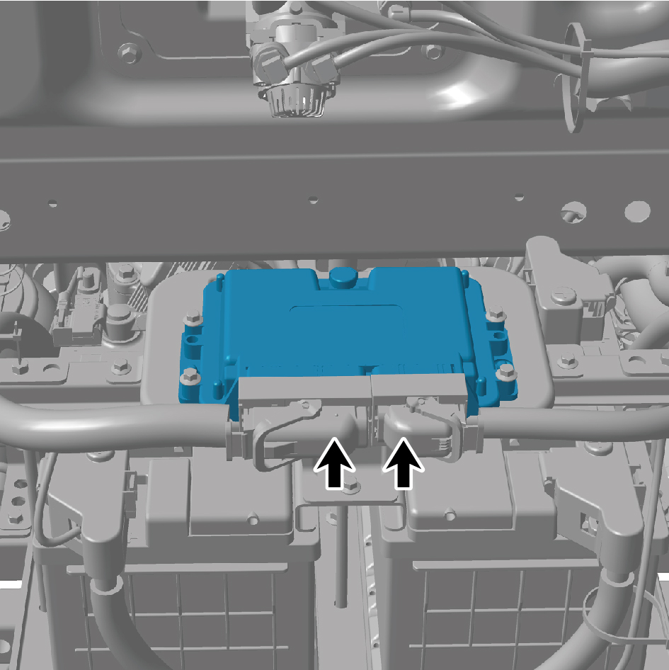
5
Remove 4 fixing bolts of the VDC assembly.
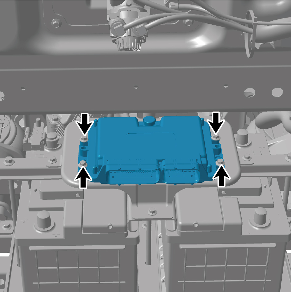
6
Remove the VDC assembly.
Installation Procedures
1
Move the VDC assembly to the mounting position.
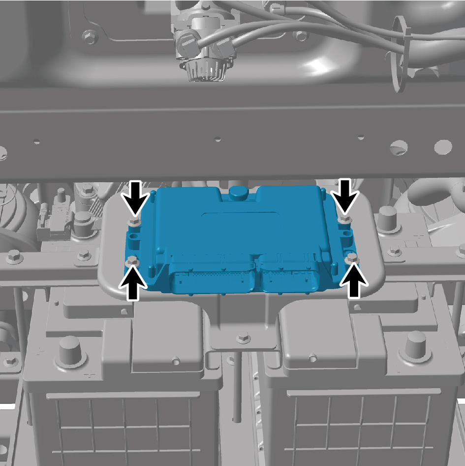
2
Install 4 fixing bolts of the VDC assembly.
Torque:(11 +/- 1.5) ft lbs
3
Connect 2 harness connectors of the VDC assembly.
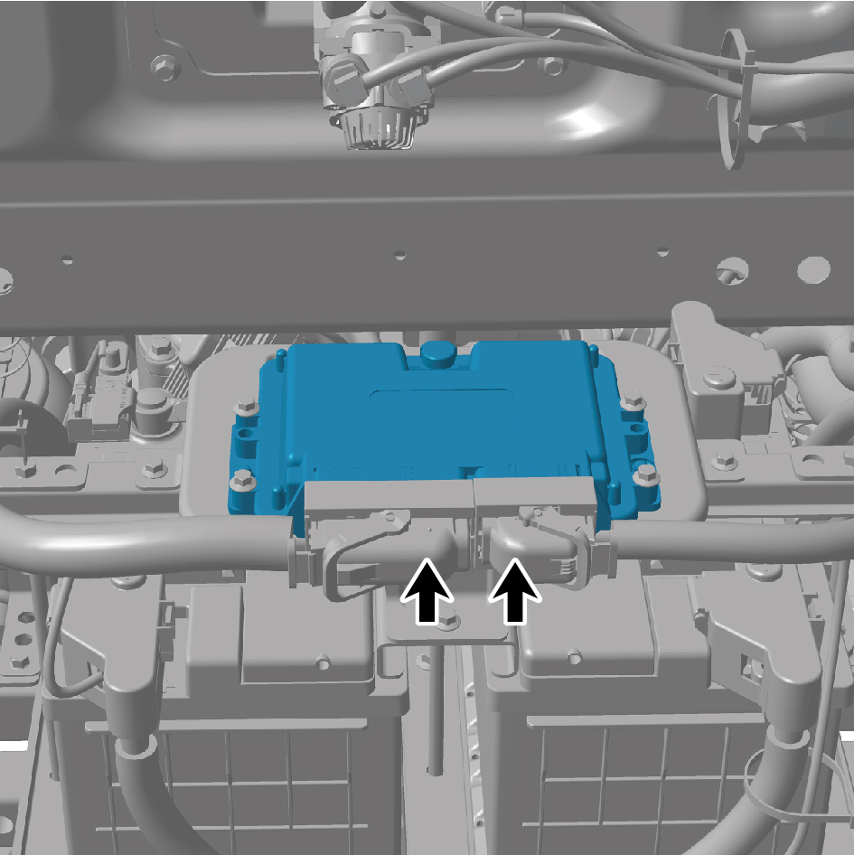
caution
The harness is firmly connected following the
principal of "insert until a click is heard for
confirmation".
4
Connect the battery negative cable.
5
Close the front flip cover plate.
6
Close the door.