← Back to Contents
7 Automotive Electrical Appliances / 7.1 Air Conditioning and Heating | PDF pages 1049-1141
7.1 Air Conditioning and Heating
7.1 Air Conditioning and Heating
7.1.1.2 Inspection of Refrigerant Air-tightness
caution
7.1.1 Description and Operation
1. Do not spray soapy water on the pins of the pressure
7.1.1.1 Refrigerant Leakage Detection
sensor/pressure switch plastic case.
caution
2. If it is necessary to check if there is a leakage at the
1. Do not use fluorescent dyes to detect leakage in the
pins of the pressure sensor/pressure switch plastic
refrigeration system, otherwise the compressor may be
case, visual inspection can be carried out. If there is a
damaged.
leakage, there will be refrigerant residue at the pins of
2. To detect leakage in the refrigeration system, a
the plastic case. If it is not a leakage from the pressure
refrigerant leak detector must be used for leak
sensor/pressure switch itself, there will be no impurities
detection.
or refrigerant oil stains at the pins of the plastic case.
1. Measure the pressure of the A/C system pipeline to confirm
3. If it is confirmed that the leakage is caused by
if there is any residual refrigerant in the A/C system.
damage to a component in the A/C system, please
replace it and perform pressure and leakage testing. Do
2. Refill the refrigerant to the A/C system.
not use alkaline liquids such as soap water to test the
caution
leakage of the pressure sensor/pressure switch and
1. Vacuumize the A/C system before filling.
other electrical components, otherwise internal
corrosion and damage of the pressure sensor and
2. Fill refrigerant with the same model and amount as
refrigerant leakage may occur.
indicated on the refrigerant nameplate.
1. Use a refrigerant leak detector with an accuracy of 10g to
3. Conduct testing under the following conditions.
check if the system is leaking normally on a annual basis or
1. The vehicle is in a stationary state with the screen
at shorter interval.
illuminated.
2. If abnormal leakage is found and the system needs to be
2. Ensure good ventilation in the working environment.
disassembled (repaired or replaced with hoses, fittings,
etc.), all refrigerant in the system shall be recovered.
3. Use a refrigerant leakage detector to check for refrigerant
leakage in the A/C system and repeat the test 2-3 times.
3. After leak detection and repair, refrigerant vacuumizing/
pressure holding/filling of the system must be carried out.
Note
7.1.1.3 Refrigerant Recovery
The leakage detector may react to volatile gases that
are not refrigerants, such as gasoline vapors, exhaust
caution
gases, etc.
1. In practical operation, refrigerant maintenance
equipment must be used. Please refer to the equipment
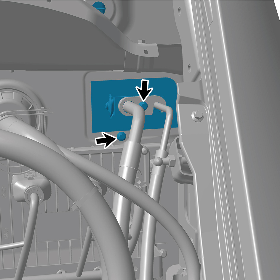
manufacturer's user manual for specific instructions on
how to use the equipment.
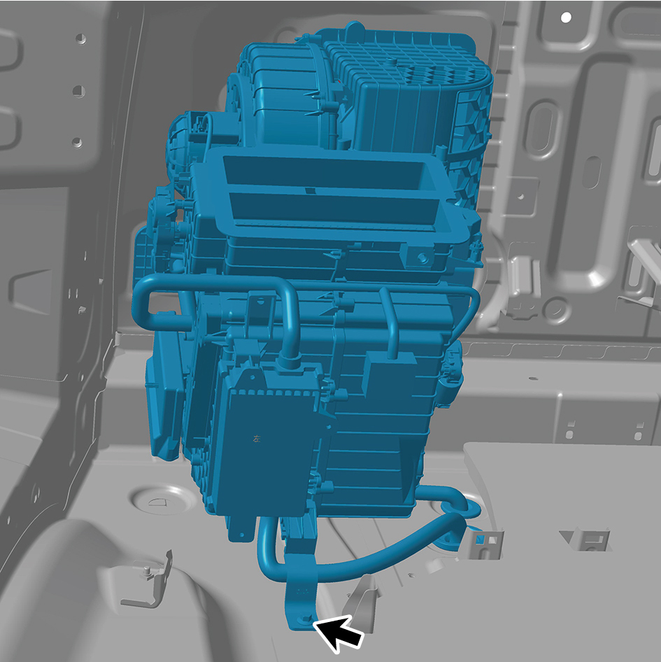
2. In the event of an accidental emission of the system,
the work site must be adequately ventilated before
continuing maintenance.
3. For further instructions on health and safety, please
refer to the instructions provided by refrigerant and
lubricant manufacturers.
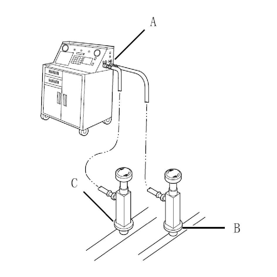
1. As shown in the figure, connect the refrigerant recovery/
recirculation/filling equipment (A) or other equipment with
the same function to the high-pressure maintenance
interface (B) and low-pressure maintenance interface (C)
according to the instructions of the equipment
manufacturer.
2. After the recovery process, measure the amount of
2. Vacuumize the system.
refrigerant oil discharged from the A/C system. Before
7.1.1.5 Refrigerant Filling
filling, ensure that an equal amount of new refrigerant oil is
caution
filled back into the A/C system.
1. After filling refrigerant, make sure to preheat the
7.1.1.4 Vacuumizing Refrigerant System
engine for at least 3 minutes when turning on the A/C
caution
switch for the first time to prevent damage.
When the A/C system is exposed to the atmosphere
2. After refrigerant filling, set the temperature to
(such as during installation and repair), refrigerant
maximum cooling under idle conditions, adjust the
recovery/recirculation/filling equipment must be used for
blower to high speed, and let the compressor run in for
vacuumizing. However, if the system is disassembled
3 minutes or longer.
for several days, the fluid reservoir/desiccant shall be
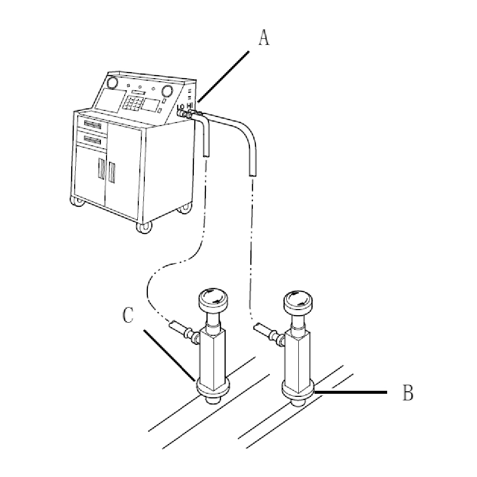
1. As shown in the figure, connect the refrigerant recovery/
replaced and the system shall be vacuumized for
recirculation/filling equipment (A) or other equipment with
several hours.
the same function to the high-pressure maintenance
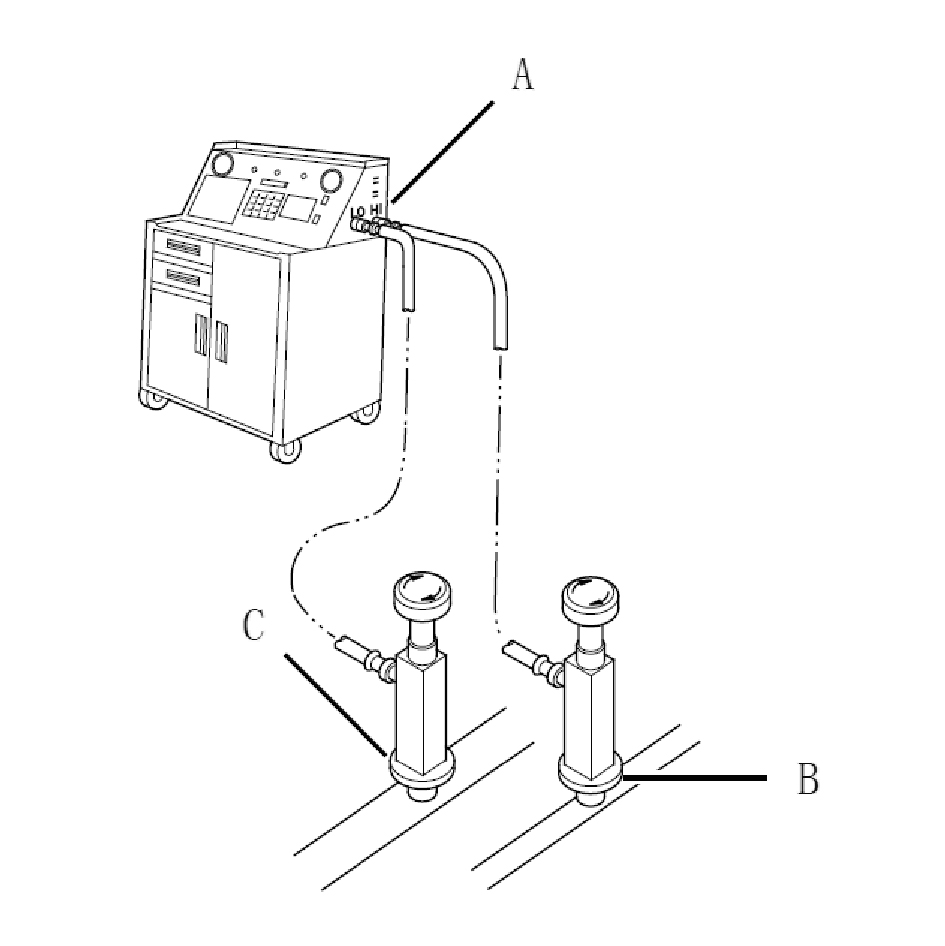
1. As shown in the figure, connect the refrigerant recovery/
interface (B) and low-pressure maintenance interface (C)
recirculation/filling equipment (A) or other equipment with
according to the instructions of the equipment
the same function to the high-pressure maintenance
manufacturer.
interface (B) and low-pressure maintenance interface (C)
according to the instructions of the equipment
manufacturer.
1. Do not operate the compressor before adding
refrigerant, as the compressor cannot function
properly without any refrigerant and may overheat.
2. Check the amount of refrigerant through
measurement rather than the observation holes.
3. It is only allowed to fill refrigerant into the A/C
system when the engine is stopped.
7.1.1.6 Refrigerant Oil Balance
caution
1. To replace any of the following components such as
condenser, evaporator, pipeline, hose, or compressor, it
is necessary to add refrigerant oil.
2. the used refrigerant oil according to regulations.
3. Do not mix brands or types of refrigerant oils,
otherwise the compressor will be damaged.
2. Vacuumize the system.
4. The refrigerant oil has strong moisture absorption, so
3. Fill a specified amount of refrigerant to the system.
when removing any component of the A/C system, it is
caution
necessary to immediately block the interface with a plug
Do not overfill, otherwise the compressor will be
or plastic tape to isolate it from the air.
damaged.
5. Do not splash the refrigerant oil onto the vehicle,
4. Check for refrigerant leakage.
otherwise the paint layer will be damaged; If refrigerant
oil splashes onto the paint layer, it shall be immediately
caution
rinsed off.
1. Do not spray soapy water on the pins of the
1. Remove the compressor.
pressure sensor/pressure switch plastic case.
2. Drain the refrigerant oil from the suction and exhaust ports
2. Check if there is a leakage at the pins of the
of the compressor into the same container.
pressure sensor/pressure switch plastic case, visual
inspection can be carried out. If there is a leakage,
caution
there will be refrigerant residue at the pins of the
1. Drain the refrigeration oil into a clean, graduated
plastic case. If it is not a leakage from the pressure
container.
sensor/pressure switch itself, there will be no
impurities or refrigerant oil stains at the pins of the
2. During the operation, avoid foreign objects and
plastic case.
moisture from entering the compressor and
refrigerant oil.
3. If it is confirmed that the leakage is caused by
damage to a component in the A/C system, please
3. When draining oil, rotate the compressor to
replace it and perform pressure and leakage testing.
facilitate the discharge of refrigerant oil (traditional
Do not use alkaline liquids such as soap water to test
compressor).
the leakage of the pressure sensor/pressure switch
4. When draining oil, change the tilt angle of the
and other electrical components, otherwise internal
compressor to facilitate the discharge of refrigerant
corrosion and damage of the pressure sensor and
oil (electric compressor).
refrigerant leakage may occur.
3. Record the amount of refrigerant oil released from the
5. Check the system performance.
removed compressor.
caution
caution
This measurement value will be used when installing
the replaced/repaired compressor.
4. Discard the used refrigerant oil properly.
5. The replaced/repaired compressor comes with a certain
capacity of refrigerant oil. Before installing the replaced/
repaired compressor, it is necessary to drain or add some
refrigerant oil.
caution
1. Refer to the amount of refrigerant oil discharged
when removing the compressor.
2. Subtract the amount of refrigerant oil discharged
during removal from the amount of refrigerant oil in
the replaced/repaired compressor, and the difference
is the amount of refrigerant oil that needs to be
discharged.
3. If the amount of refrigerant oil in the replaced/
repaired compressor is small, the difference in the
previous step is the amount of refrigerant oil that
needs to be added.
6. Discharge or add refrigerant oil in the replaced/repaired
compressor based on the calculated value.
7.1.2 Specifications
7.1.2.1 Fastener Specifications
Range Of Torque
Fastener Specifications
Specifications
Foot Pounds of Torque (ft lbs)
The fixing nut connecting the air
conditioning compressor assembly and
(18.5 +/- 1.5) ft lbs
M8
the air conditioning compressor bracket
The fixing bolt connecting the bracket of
(18.5 +/- 1.5) ft lbs
M8
the air conditioning compressor to the
frame on the subframe
HVAC assembly (including PTC) - fixing
bolt connecting the front left to the
(7.5 +/- .75) ft lbs
M8
vehicle body
HVAC assembly (including PTC) - fixing
bolt connecting the front left and front
(5 +/- .75) ft lbs
M6
wall crossbeam inner panel assembly
HVAC assembly (including PTC) - fixing
nut connecting the front left to the
(5 +/- .75) ft lbs
M6
vehicle body
HVAC assembly (including PTC) - fixing
bolt connecting the front right to the
(7.5 +/- .75) ft lbs
M8
vehicle body
HVAC assembly (including PTC) - fixing
bolts connecting the front right and front
(5 +/- .75) ft lbs
M6
crossbeam inner panel assembly
HVAC assembly (including PTC) - fixing
nut connecting the front right to the
(5 +/- .75) ft lbs
M6
vehicle body
HVAC assembly (including PTC) - fixing
bolts connecting the rear to the vehicle
(7.5 +/- .75) ft lbs
M8
body
HVAC assembly (including PTC) - fixing
bolts connecting the rear and rear
(7.5 +/- .75) ft lbs
M8
evaporator to the connecting pipe
assembly
HVAC assembly (including PTC) - fixing
bolts connecting the rear to the vehicle
(5 +/- .75) ft lbs
M6
body
7.1.2.2 Technical Parameters
A/C System
Item
S/N
Structural Parameters
Cooling capacity≥6.7kW - face blowing
Blower capacity for face blowing, full cool≥600m³/h
Performance parameters
1
Heating capacity≥8kW
Refrigerant specifications
2
HFC-134a
Refrigerant capacity
3
29.9 oz +/- 1.76 oz
Refrigerant leakage rate
< 1.41 oz/year
4
Model of refrigerant oil
5
POE RB68
Amount of refrigerant oil
6
6.76 oz
Compressor
Item
S/N
Structural Parameters
1
Model
EBJ33C-MD01
Type
Electric vortex type
2
Displacement
3
33CC
Rated voltage (high voltage)
4
800V
Working voltage range
5
480V~920V
Rated voltage (low voltage)
6
24V
Input voltage range
7
18~36V
Working temperature
8
68*F - 212*F
Rated input power
4 hp
9
Rated speed
7000rpm
10
Maximum speed
12000rpm
11
≥50MΩ
12
Insulation resistance
Heater
Item
S/N
Structural Parameters
YJ0174, YJ0175, YJ0176
1
Model
Rated voltage (high voltage)
2
800V
Working voltage range
3
450V~940V
Rated voltage (low voltage)
4
24V
Input voltage range
5
18~32V
Working temperature
6
-40*F - -121*F
7.1.3 Decomposition Diagram
7.1.3.1 Decomposition Diagram
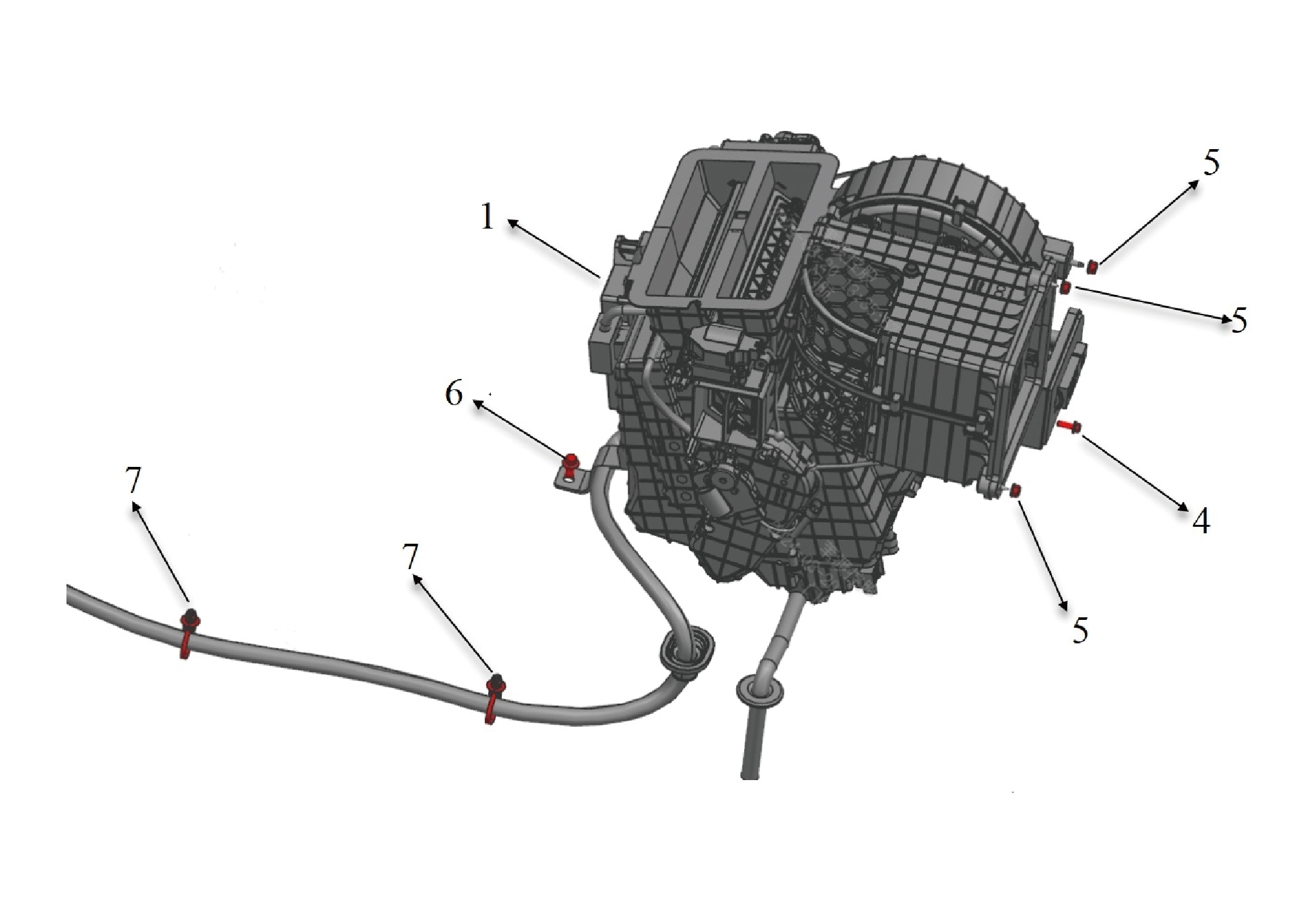
1.
6.
Hexagon Flange Bolt
HVAC Device Assy-Frt Lh
7.
4.
Hexagon Flange Bolt
Tie-Fir Tree
5.
Hexagon Flange Lock Nut_All Metal
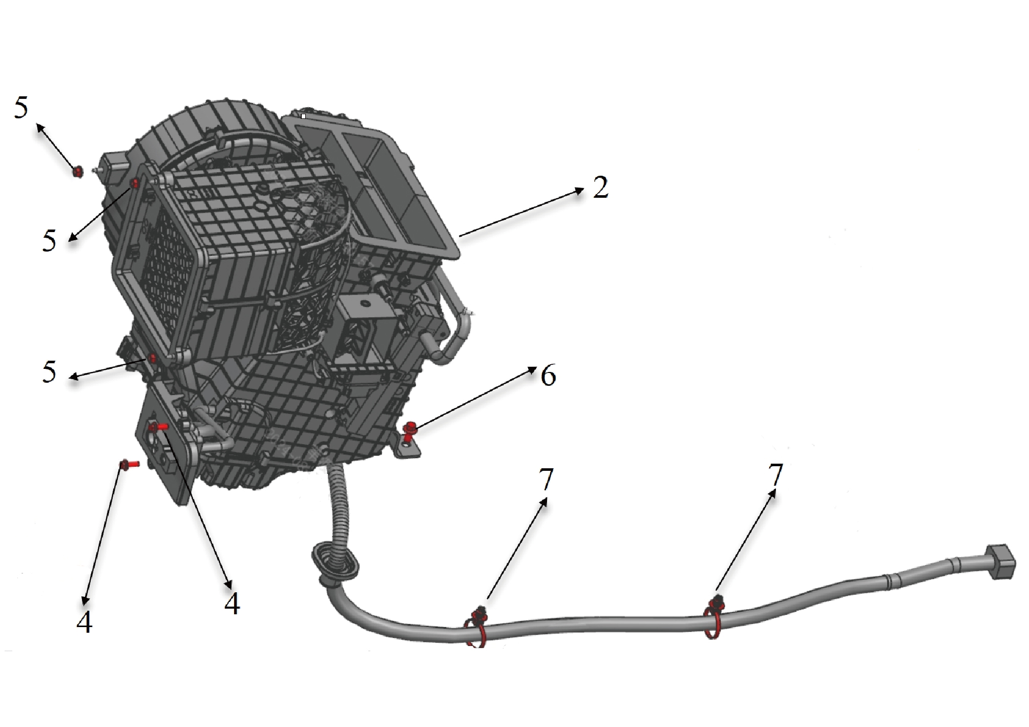
2.
6.
Hexagon Flange Bolt
HVAC Device Assy-Frt Rh
7.
4.
Hexagon Flange Bolt
Tie-Fir Tree
5.
Hexagon Flange Lock Nut_All Metal
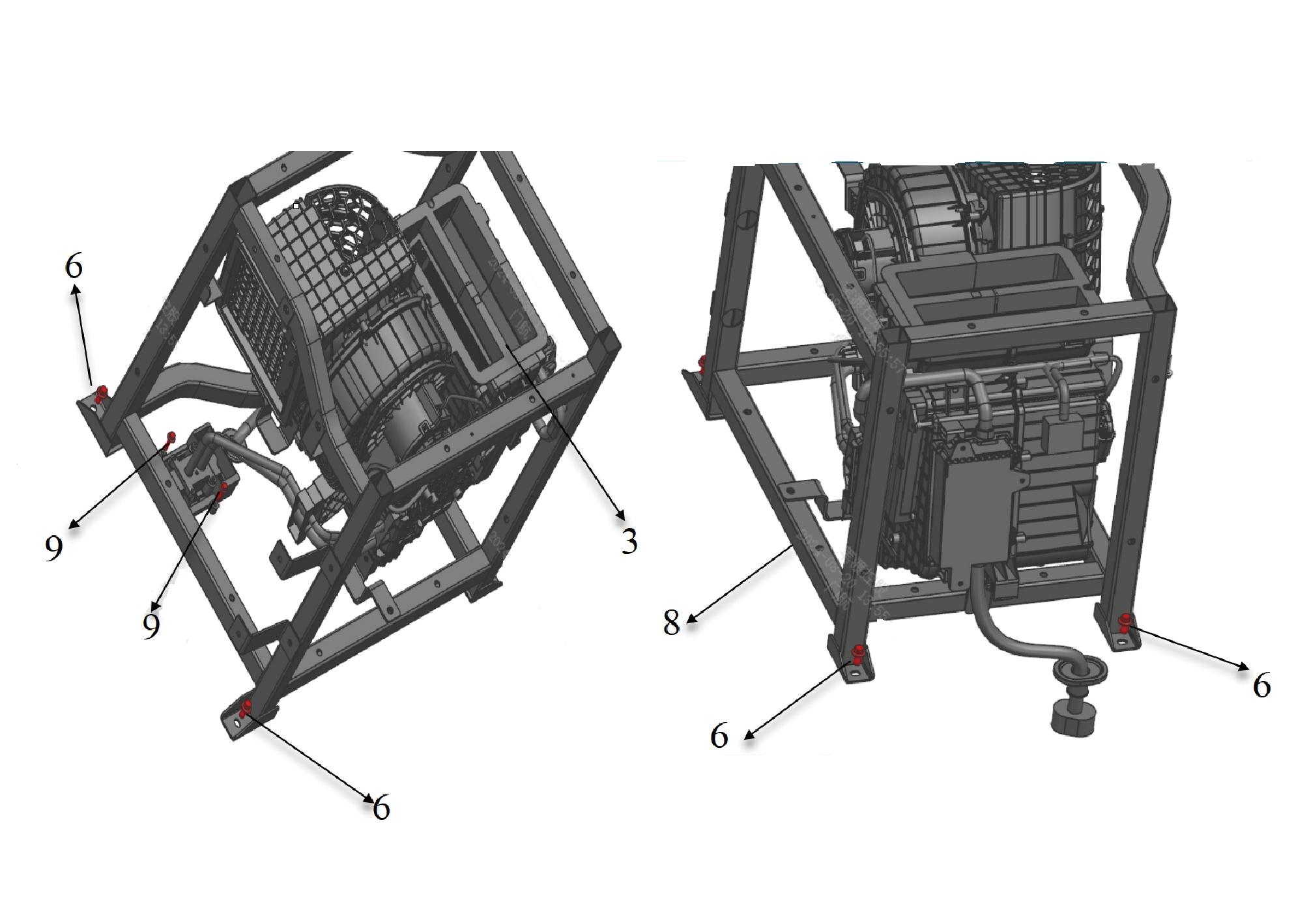
3.
8.
HVAC Device Assy-Rr
Fixed Frame After Air Conditioning
6.
Hexagon Flange Bolt
9.
Hexagon Flange Bolt
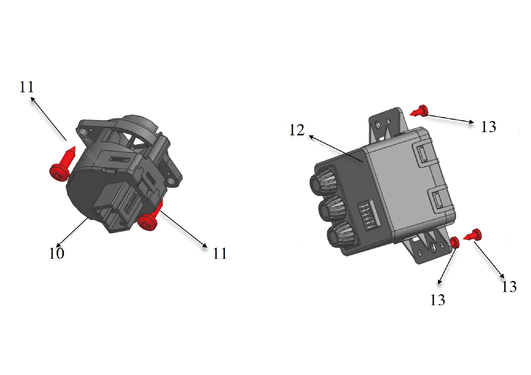
10.
12.
Room Temperature Sensor
Aroma Generator Assembly In New Energy Vehicles
11.
13.
Self-Tapping Screw
Self-Tapping Screw
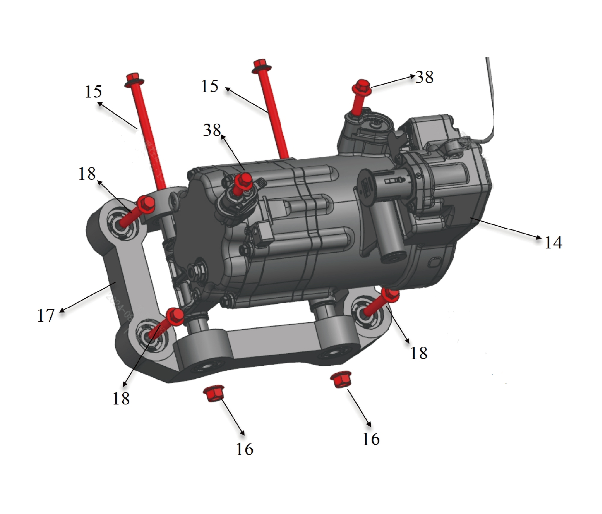
14.
17.
Compressor Assy
Compressor Bracket
15.
18.
Hexagon Flange Bolt
Compressor Mounting Bolts
16.
Hexagon Flange Lock Nut_All Metal
38.
Hexagon Flange Bolt
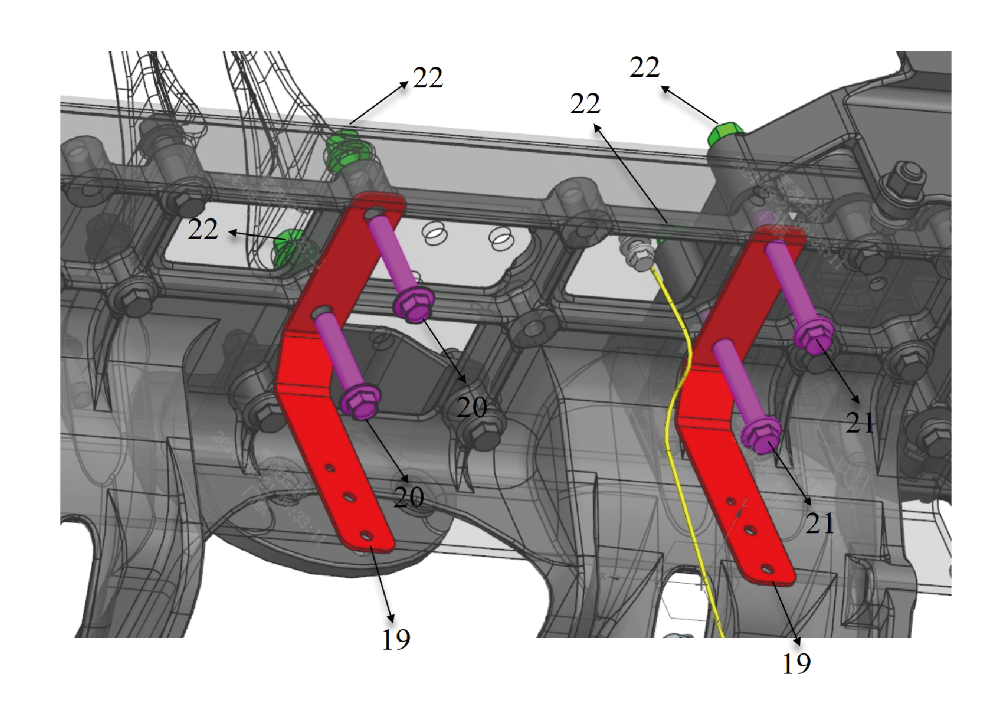
19.
21.
Hexagon Flange Bolt
Stent
20.
Hexagon Flange Bolt
22.
Hexagon Flange Lock Nut_All Metal
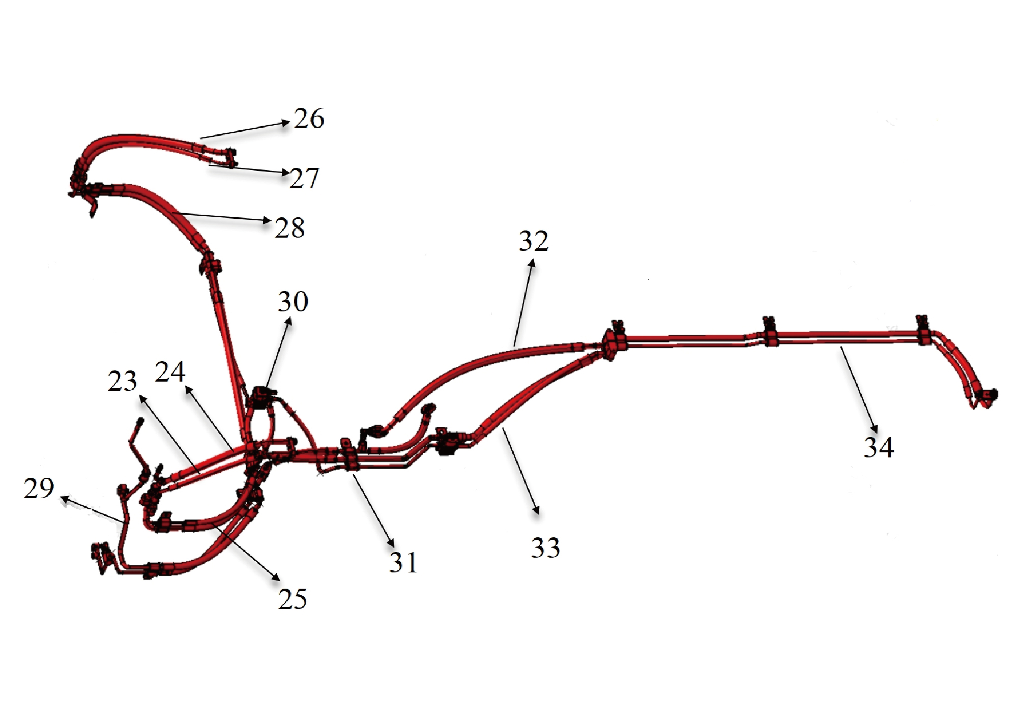
23.
29.
Lh Steanm to Front S0V Line Assy 1 Cold Steam End
Condensor Inlet and Outlet Tube Assy
24.
30.
Left Steam to Pre-S0V Line Assy 1 Stepress End
Pipeline Assembly From SOV to Evaporator In New
Energy Vehicles
25.
31.
Left Evaporator to SOV Line Assy 2
Pressure Cooling Tube Tripler
26.
32.
Return Air Tube-Rransfer Tube
Right Evaporator to SOV Valve Line Assy Autoclaclve
End
27.
33.
Rh Evaporator to SOV Valve Line Assy Cold Steam
Adapter Pipe at the Outlet of SOV In New Energy
End
Vehicles
28.
34.
Rear Evaporator to Transfer Line Assy
Rnght Evaporator to SOV Valve Line Assy 2
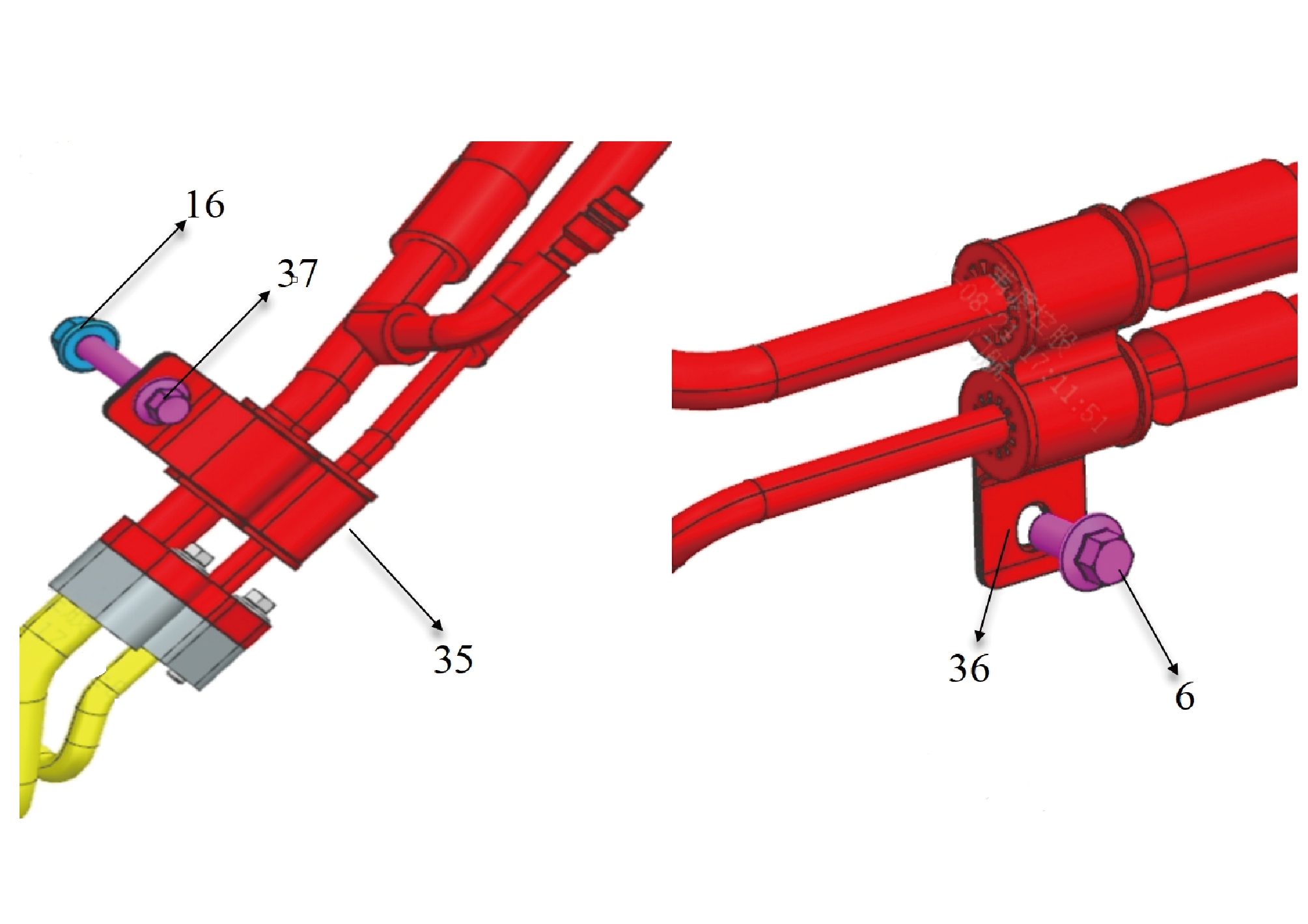
6.
Hexagon Flange Bolt
36.
Pipe Clamp
16.
Hexagon Flange Lock Nut_All Metal
37.
Hexagon Flange Bolt
35.
Pipe Clipφ9-φ12
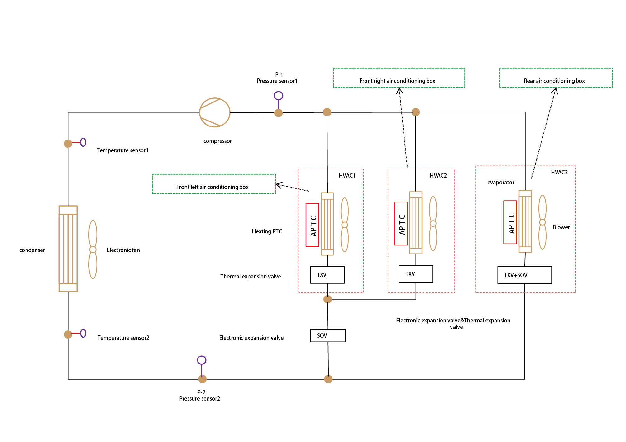
7.1.4 System Schematic Diagram
7.1.4.1 System Working Principle
7.1.4.2 Electrical Schematic Diagram
7.1.5 Diagnostic Information and Steps
7.1.5.1 Diagnosis Description
Understanding and familiarizing oneself with the working principles of air conditioning and heating before diagnosing faults in air
conditioning and heating, and then starting system diagnosis, can help determine the correct fault diagnosis steps when a fault
occurs, and more importantly, it can help determine the situation described by the customer belongs to normal operation. Any
fault diagnosis of air conditioning and heating should start with routine inspection, guiding maintenance personnel to take the
next logical step for fault diagnosis. Understanding and correctly using the diagnostic process can shorten the diagnosis time and
avoid misjudgment of faulty parts.
7.1.5.2 Routine Inspection
• Check the after-sales installation devices that may affect the operation of the air conditioning and heating system, ensuring that
these devices do not affect the operation of the air conditioning and heating system.
• Inspect system components that are easily accessible or visible to make sure they are not visibly damaged or have conditions
that could cause failure.
7.1.5.3 Fault Symptom Table
Symptom
Suspected Faulty Project
Measures
1. Blockage of air conditioning filter
Clean or replace the air conditioning
element
filter element.
Check the power supply harness of the
air conditioning blower. Refer to Left Air
Conditioning Blower Power Supply
2. Fault in the power supply harness of
Circuit Fault.Right Air Conditioning
the air conditioning blower
Blower Power Supply Circuit Fault.
Power Supply Circuit Fault Of Sleeper
Air Conditioning Blower
Check the PWM control signal wiring
3. Fault in the wiring harness of the
harness between the driver's blower,
PWM control signal for the air
The air conditioning blower is not
passenger's blower, sleeper blower, and
conditioning blower
producing air or the air volume is low
AC.
Replace the driver's blower,
passenger's blower, and sleeper blower.
Refer to Replacement Of HVAC
Assembly (including PTC) - Front Left .
4. Air conditioning blower fault
Replacement Of HVAC Assembly
(Including PTC) - Front Right.
Replacement Of HVAC Assembly
(Including PTC) - Rear
Replace the air conditioning controller.
Refer to Replacement Of HVAC
5. Air conditioning controller fault
Assembly (Including PTC) - Front Right
1. Blockage of air conditioning filter
Clean or replace the air conditioning
element
filter element.
Air conditioning system not cooling or
Check for refrigerant leakage in the air
insufficient cooling
2. Too much or too little refrigerant
conditioning system and add it again if
necessary.
Symptom
Suspected Faulty Project
Measures
Check if the condenser is blocked or
3. Poor heat dissipation of condenser
covered by foreign objects.
4. Evaporator blockage or foreign object
Check if the evaporator is blocked or
coverage
covered by foreign objects.
Refer to Left Air Conditioning
Evaporation Temperature Sensor Fault.
Right Air Conditioning Evaporation
5. Evaporator temperature sensor fault
Temperature Sensor Fault.Sleeper Air
Conditioning Evaporation Temperature
Sensor Fault
6. Fault in the power supply circuit of the
Refer to Compressor Power Supply
air conditioning compressor
Circuit Fault
Check the CAN communication harness
7. CAN communication harness fault
between the air conditioning
between air conditioning compressor
compressor and AC.
and AC
8. High voltage wiring harness fault of
Check the high-pressure wiring harness
air conditioning compressor
of the air conditioning compressor.
Check the high-pressure interlock
9. High pressure interlock harness fault
harness of the air conditioning
of air conditioning compressor
compressor.
1. Blockage of air conditioning filter
Clean or replace the air conditioning
element
filter element.
2. Fault in PTC power supply circuit
Refer to PTC Power Supply Circuit Fault
Check the CAN communication harness
3. CAN communication harness fault
between the driver PTC, passenger
between PTC and AC
The air conditioning system is not
PTC, sleeper PTC, and AC.
heating or heating is insufficient
Check the driver PTC, passenger PTC,
4. Fault in PTC high-voltage wiring
and sleeper PTC high-voltage wiring
harness
harness.
Check the high-voltage interlock wiring
5. PTC high-voltage interlock harness
harness of the driver PTC, passenger
fault
PTC, and sleeper PTC.
7.1.5.4 DTC Confirmation
1.Connect the diagnostic instrument to the diagnostic interface, read and record the DTC, and then clear the DTC.
2. Restart the vehicle.
3. Read the fault code of the control system again to confirm whether the system has a fault code output.
– Yes:Diagnose based on the output fault code.
– No:Perform intermittent fault checks, refer to Inspection Of Intermittent Faults
7.1.5.5 List Of Diagnostic Trouble Codes (DTC)
Fault Description
Exclusion Method
Fault Code
High battery voltage
B111717
Refer to Air Conditioning Controller
Power Fault
Low battery voltage
B111716
Lost communication with XF-AC
U115087
(0x18FF2F19x)
Lost communication with ACP_AC1
U115187
(0x18FF2B19x)
Lost communication with PTC1_AC
U115287
(0x18FF2C19x)
Lost communication with PTC2_AC
U115387
(0x18FF2D19x)
Lost communication with PTC3_AC
U115487
(0x18FF2E19x)
Lost communication with BDCU_To_
U014087
AC_Front(0x18FF1121x)
Refer to Communication Fault Of Air
Conditioning Controller
Lost communication with CDC_VDHR
U015687
(0x18FEC1EEx)
Lost communication with VDC_CCVS
U012287
(0x18FEF100x)
Lost communication with TGW_TD_
U019887
Time(0x18FEE6EEx)
U007D88
BCANFD2 BusOff
BCANFD2 CAN H short-circuit fault to
U007D89
the ground
BCANFD2 CAN H short-circuit fault to
U007D90
the ground
U115F87
The CANFD transmission is abnormal
Front - Interior temperature sensor open
B258113
circuit
Refer to Front Interior Temperature
Short-circuited front - interior
Sensor Fault
B258111
temperature sensor
Rear-interior temperature sensor open
B258613
circuit
Refer to Rear Interior Temperature
Sensor Fault
Rear-interior temperature sensor short-
B258611
circuited
Actuator 1 of the front left mode damper
B250117
motor is faulty
Refer to Left Air Conditioning Mode
Damper Motor Fault
Actuator 2 of the front left mode damper
B250217
motor is faulty
Front left circulation damper actuator is
Refer to Left Air Conditioner Internal
B250317
faulty
And External Circulation Motor Fault
Fault Description
Exclusion Method
Fault Code
Front left heating and cooling valve
Refer to Left Air Conditioning Cooling
B250417
actuator is faulty
And Heating Motor Fault
Front left air conditioner evaporation
B258213
temperature sensor open circuit
Refer to Left Air Conditioning
Evaporation Temperature Sensor Fault
Front left air conditioner evaporation
B258211
temperature sensor is short-circuited
Open the circuit for the exhaust air
B258313
temperature sensor in the front left air
Refer to Left Air Conditioning Outlet
conditioner
Temperature Sensor Fault
The exhaust air temperature sensor of
B258311
the front left air conditioner is short-
circuited
Actuator 1 of the front right mode
B250517
damper motor is faulty
Refer to Right Air Conditioning Mode
Damper Motor Fault
Actuator 2 of the front right mode
B250617
damper motor is faulty
Front right circulation damper actuator
Refer to Right Air Conditioner Internal
B250717
is faulty
And External Circulation Motor Fault
The actuator of the front right heating
Refer to Right Air Conditioning Cooling
B250817
and cooling valve is faulty
And Heating Motor Fault
Front right air conditioning evaporative
B258413
temperature sensor open circuit
Refer to Right Air Conditioning
Evaporation Temperature Sensor Fault
Short-circuited evaporation temperature
B258411
sensor of front right air conditioner
Open the air outlet temperature sensor
B258513
on the front right air conditioner
Refer to Right Air Conditioning Outlet
The outlet air temperature sensor of the
Temperature Sensor Fault
B258511
front right air conditioner is short-
circuited
Rear air conditioner evaporation
B258713
temperature sensor open circuit
Refer to Sleeper Air Conditioning
The evaporation temperature sensor of
Evaporation Temperature Sensor Fault
B258711
the rear left air conditioner is short-
circuited
Rear air conditioner air temperature
B258813
sensor open circuit
Refer to Sleeper Air Conditioning
Temperature Sensor Fault
The outlet air temperature sensor of the
B258811
rear air conditioner is shorted
7.1.5.6 Air Conditioning Controller Power Fault
1.DTC Monitoring Logic
Description
DTC Trigger Conditions
Faulty Part
DTC Code
1. Main battery
The power supply voltage exceeds 32.5V for more than
High battery voltage
B111717
2. Low voltage
1 second
charging system
3. Wiring harness
The power supply voltage is lower than 17.5V for more
Low battery voltage
4. Air
B111716
than 1 second
conditioning
controller
2.Circuit Diagram
Smart Junction
Smart Junction
Box - Chassis
Box - Body
Battery
19
I3_B_C
B08-4
B01-1
19
I3_C_B
Total body power
B12-1
supply B+ L22
controller KL30 P204
controller KL30 P204
controller KL30 P204
Air conditioning
Air conditioning
Air conditioning
Power source
Power source
P204b
P204a
Air conditioning controller KL30 P204
Front
Rear
C67-2
C73-2
air
air
condi-
condi-
tioner
tioning
SOV
SOV
C67-1
C73-1
Controls -
Controls -
K103
K102
21
I3_C_B
20
I3_C_B
I3_B_C
I3_B_C
21
20
Former SOV- K102
Power KL30 P204e
Power KL30 P204a
After SOV- K103
B42-3
B42-40
B43-1
B42-2
Air conditioning controller A/B
B42-20
B43-13
Ground Z02
Ground Z02
Ground Z02
G24
3. Diagnostic Steps
Step 1:DTC Confirmation. Refer to DTC Confirmation
Step 2:Routine Inspection. Refer to Routine Inspection
Step 3:Check if there are any other module power fault codes besides the air conditioning controller?
Check the main battery. Refer to Inspection Of The Main Battery
– Yes:
Check the low-voltage charging system. Refer to DCDC1 Low-voltage Charging System Fault
Next step
– No:
Step 4:Check the power and grounding harness of the air conditioning controller.
Step 5:Rewrite the configuration code, reload the software, and upgrade the air conditioning controller.
Step 6:Replace the air conditioning controller. Refer to Replacement Of HVAC Assembly (Including PTC) - Front Right
Step 7:Clear and confirm DTC.
7.1.5.7 Communication Fault Of Air Conditioning Controller
1.DTC Monitoring Logic
Description
DTC Trigger Conditions
Faulty Part
DTC Code
Lost communication
If all XF-AC packets are lost within 10 sending cycles,
with XF-AC
U115087
the fault is rectified
(0x18FF2F19x)
Lost communication
If all ACP_AC1 packets are lost within 10 sending
with ACP_AC1
U115187
cycles, the fault is rectified
(0x18FF2B19x)
Lost communication
If all PTC1_AC packets are lost within 10 sending
with PTC1_AC
U115287
cycles, the fault is rectified
(0x18FF2C19x)
Lost communication
If all PTC2_AC packets are lost within 10 sending
with PTC2_AC
U115387
cycles, the fault is rectified
(0x18FF2D19x)
Lost communication
1.Wiring harness
If all PTC3_AC packets are lost within 10 sending
with PTC3_AC
U115487
2. Air
cycles, the fault is rectified
(0x18FF2E19x)
conditioning
controller
Lost communication
If all BDCU_To_AC_Front packets are lost within 10
with BDCU_To_AC_
U014087
sending cycles, the fault is rectified
Front(0x18FF1121x)
Lost communication
If all CDC_VDHR packets are lost within 5 seconds, the
with CDC_VDHR
U015687
fault is rectified
(0x18FEC1EEx)
Lost communication
If all VDC_CCVS packets are lost within 10 sending
with VDC_CCVS
U012287
intervals (1s), the fault is rectified
(0x18FEF100x)
Lost communication
If all TGW_TD_Time packets are lost within 5 seconds,
with TGW_TD_Time
U019887
the fault is rectified
(0x18FEE6EEx)
U007D88
BCANFD2 BusOff
Bus Off
Description
DTC Trigger Conditions
Faulty Part
DTC Code
BCANFD2 CAN H
short-circuit fault to the
CAN bus exception
U007D89
ground
BCANFD2 CAN H
short-circuit fault to the
CAN bus exception
U007D90
ground
The CANFD
Abnormal packets sent by the CANFD module are
U115F87
transmission is
detected for more than 300ms
abnormal
2.Circuit Diagram
Air conditioning compressor
C68-6
C68-5
Air conditioning
Air conditioning
CAN-H K222a
CAN_L K223a
Right side air
Left side air
Sleeper air
Fragrance
conditioner
conditioner
conditioner
33
24
I8_C_B
I8_C_B
B81-8
B81-7
B54-8
B52-8
B55-3
B54-7
B52-7
B55-2
BCANFD2
33
24
I8_B_C
I8_B_C
Air conditioning
Air conditioning
Air conditioning
Air conditioning
Air conditioning
Air conditioning
Air conditioning
Air conditioning
Air conditioning
Air conditioning
CAN_H K222a
CAN_H K222a
CAN_H K222b
CAN_H K222a
CAN_H K222c
CAN_L K223a
CAN_L K223a
CAN_L K223a
CAN_L K223b
CAN_L K223c
BCANFD2-H BH02a
BCANFD2-L BL02a
Air conditioning
Air conditioning
CAN_H K222
CAN_L K223
B43-22
B43-23
B42-21
B42-22
Air conditioning controller A/B
3. Diagnostic Steps
Step 1:DTC Confirmation. Refer to DTC Confirmation
Step 2:Routine Inspection. Refer to Routine Inspection
Step 3:Check the BCAND2 bus communication harness. Refer to Inspection Of BCAND2 Bus Network Integrity
Step 4:Check the air conditioning CAN bus communication harness. Refer to Inspection Of The Air Conditioning CAN Bus
Network Integrity
Step 5:Rewrite the configuration code, reload the software, and upgrade the air conditioning controller.
Step 6:Replace the air conditioning controller. Refer to Replacement Of HVAC Assembly (Including PTC) - Front Right
Step 7:Clear and confirm DTC.
7.1.5.8 Front Interior Temperature Sensor Fault
1.DTC Monitoring Logic
Description
DTC Trigger Conditions
Faulty Part
DTC Code
Front - Interior
1.Wiring harness
temperature sensor
Sensor voltage exceeds 4.95V for more than 1 second
2. Front interior
B258113
open circuit
temperature
sensor
Short-circuited front -
3. Air
The sensor voltage is below 0.05V for more than 1
B258111
interior temperature
conditioning
second
sensor
controller
2.Circuit Diagram
Temperature sensor in front car
Sensor
Fan
IP12-2
IP12-1
IP12-4
IP12-3
supply + K138a
Temperature signal K209
sensorily K135d
12V power
Ground Z14b
Rear interior temperature sensor
Fan
Sensor
26
I2_IP_B
B68-1
B68-4
B68-3
B68-2
Ground Z14
26
I2_B_IP
12V+ power supply K138b
24
25
I2_IP_B
I2_IP_B
Temperature signal K135e
Temperature signal K214
front car 12V power supply K138a
Temperature sensor inside the
Fragrance
Ground Z26
24
25
I2_B_IP
I2_B_IP
B55-4
B55-1
G16
Front car temperature
Interior temperature
sensor - Front K209
supply + K138c
sensor K135d
112V power
Ground Z11
G32
G28
sensor 12+ K138
Temperature
sensorily K135
B42-38
B43-9
B43-35
B43-14
Air conditioner controller A/B
3. Diagnostic Steps
Step 1:DTC Confirmation. Refer to DTC Confirmation
Step 2:Routine Inspection. Refer to Routine Inspection
Step 3:Check the wiring harness between the front interior temperature sensor and the air conditioning controller.
Step 4:Check if the resistance of the front car interior temperature sensor is normal?
Temperature
Resistance
Sensor
Front interior temperature
77℉
2.12KΩ - 2.25KΩ
sensor
Next step
– Yes:
Replace the front interior temperature sensor. Refer to Replacement Of Indoor Temperature Sensor
– No:
Step 5:Rewrite the configuration code, reload the software, and upgrade the air conditioning controller.
Step 6:Replace the air conditioning controller. Refer to Replacement Of HVAC Assembly (Including PTC) - Front Right
Step 7:Clear and confirm DTC.
7.1.5.9 Rear Interior Temperature Sensor Fault
1.DTC Monitoring Logic
Description
DTC Trigger Conditions
Faulty Part
DTC Code
Rear-interior
1.Wiring harness
temperature sensor
2. Rear interior
Sensor voltage exceeds 4.95V for more than 1 second
B258613
open circuit
temperature
sensor
Rear-interior
3. Air
The sensor voltage is below 0.05V for more than 1
B258611
temperature sensor
conditioning
second
short-circuited
controller
2.Circuit Diagram
Temperature sensor in front car
Sensor
Fan
IP12-2
IP12-1
IP12-4
IP12-3
supply + K138a
Temperature signal K209
sensorily K135d
12V power
Ground Z14b
Rear interior temperature sensor
Fan
Sensor
26
I2_IP_B
B68-1
B68-4
B68-3
B68-2
Ground Z14
26
I2_B_IP
12V+ power supply K138b
24
25
I2_IP_B
I2_IP_B
Temperature signal K135e
Temperature signal K214
front car 12V power supply K138a
Temperature sensor inside the
Fragrance
Ground Z26
24
25
I2_B_IP
I2_B_IP
B55-4
B55-1
G16
Front car temperature
Interior temperature
sensor - Front K209
supply + K138c
sensor K135d
112V power
Ground Z11
G32
G28
sensor 12+ K138
Temperature
sensorily K135
B42-38
B43-9
B43-35
B43-14
Air conditioner controller A/B
3. Diagnostic Steps
Step 1:DTC Confirmation. Refer to DTC Confirmation
Step 2:Routine Inspection. Refer to Routine Inspection
Step 3:Check the wiring harness between the rear interior temperature sensor and the air conditioning controller.
Step 4:Check if the resistance of the rear temperature sensor in the car is normal?
Temperature
Resistance
Sensor
Rear interior temperature
77℉
2.12KΩ - 2.25KΩ
sensor
Next step
– Yes:
Replace the Rear interior temperature sensor. Refer to Replacement Of Indoor Temperature Sensor
– No:
Step 5:Rewrite the configuration code, reload the software, and upgrade the air conditioning controller.
Step 6:Replace the air conditioning controller. Refer to Replacement Of HVAC Assembly (Including PTC) - Front Right
Step 7:Clear and confirm DTC.
7.1.5.10 Left Air Conditioning Mode Damper Motor Fault
1.DTC Monitoring Logic
Description
DTC Trigger Conditions
Faulty Part
DTC Code
1.Wiring harness
Actuator 1 of the front
The actuator cannot reach the predetermined position
2. Left air
left mode damper
B250117
within 10 seconds after starting
conditioning
motor is faulty
mode damper
motor
Actuator 2 of the front
The actuator cannot reach the predetermined position
3. Air
left mode damper
B250217
within 10 seconds after starting
conditioning
motor is faulty
controller
2.Circuit Diagram
Air conditioning controller A
B42-10
B42-12
B42-14
B42-13
B42-15
B42-16
B42-9
B42-11
cooling motor - K110
Blower foot motor
Main heating and
Main blow foot +
Master defrost +
Master defrost -
Main defrosting
Main blow foot
Main heating
feedback K115
feedback K116
motor + K109
and cooling
12V- K114
K113
K111
K112
sensorily K135a
Actuator carbon
film 5V+ K117a
Left side air
conditioner
B52-23
B52-24
B52-6
B52-4
B52-3 B52-11
B52-25
B52-18
B52-13
B52-20
Heating and cooling
motor 1
Mode motor - blow foot
Blow and defrost
B52-16
B52-17
High voltage interlock in- air
conditioning from sleeper H03
High voltage interlock in- air
conditioning from the main
driver H02
B54-16
B81-17
Right side air conditioner
Sleeper air conditioner
3. Diagnostic Steps
Step 1:DTC Confirmation. Refer to DTC Confirmation
Step 2:Routine Inspection. Refer to Routine Inspection
Step 3:Check the wiring harness between the left air conditioning mode damper motor and the air conditioning controller.
Step 4:Connect the left air conditioning mode damper motor to an external 12V power supply and observe if the left air
conditioning mode damper motor is working?
Next step
– Yes:
Replace the left air conditioning mode damper motor. Refer to Replacement Of HVAC Assembly (Including
– No:
PTC) - Front Left
Step 5:Rewrite the configuration code, reload the software, and upgrade the air conditioning controller.
Step 6:Replace the air conditioning controller. Refer to Replacement Of HVAC Assembly (Including PTC) - Front Right
Step 7:Clear and confirm DTC.
7.1.5.11 Left Air Conditioner Internal And External Circulation Motor Fault
1.DTC Monitoring Logic
Description
DTC Trigger Conditions
Faulty Part
DTC Code
1.Wiring harness
2. Left air
conditioning
Front left circulation
internal and
The actuator cannot reach the predetermined position
damper actuator is
B250317
external
within 10 seconds after starting
faulty
circulation motor
3. Air
conditioning
controller
2.Circuit Diagram
Air conditioning controller A
B42-10
B42-12
B42-14
B42-13
B42-15
B42-16
B42-9
B42-11
cooling motor - K110
Blower foot motor
Main heating and
Main blow foot +
Master defrost +
Master defrost -
Main defrosting
Main blow foot
Main heating
feedback K115
feedback K116
motor + K109
and cooling
12V- K114
K113
K111
K112
sensorily K135a
Actuator carbon
film 5V+ K117a
Left side air
conditioner
B52-23
B52-24
B52-6
B52-4
B52-3 B52-11
B52-25
B52-18
B52-13
B52-20
Heating and cooling
motor 1
Mode motor - blow foot
Blow and defrost
B52-16
B52-17
High voltage interlock in- air
conditioning from sleeper H03
High voltage interlock in- air
conditioning from the main
driver H02
B54-16
B81-17
Right side air conditioner
Sleeper air conditioner
3. Diagnostic Steps
Step 1:DTC Confirmation. Refer to DTC Confirmation
Step 2:Routine Inspection. Refer to Routine Inspection
Step 3:Check the wiring harness between the left air conditioning internal and external circulation motor and the air
conditioning controller.
Step 4:Connect the left air conditioner's internal and external circulation motor to a 12V power supply and observe if the left air
conditioner's internal and external circulation motor is working?
Nex step
– Yes:
Replace the left air conditioning internal and external circulation motor. Refer to Replacement Of HVAC
– No:
assembly (including PTC) - Front Left
Step 5:Rewrite the configuration code, reload the software, and upgrade the air conditioning controller.
Step 6:Replace the air conditioning controller. Refer to Replacement Of HVAC Assembly (Including PTC) - Front Right
Step 7:Clear and confirm DTC.
7.1.5.12 Left Air Conditioning Cooling And Heating Motor Fault
1.DTC Monitoring Logic
Description
DTC Trigger Conditions
Faulty Part
DTC Code
1.Wiring harness
2. Left air
conditioning
Front left heating and
The actuator cannot reach the predetermined position
cooling and
cooling valve actuator
B250417
within 10 seconds after starting
heating motor
is faulty
3. Air
conditioning
controller
2.Circuit Diagram
Air conditioning controller A
B42-10
B42-12
B42-14
B42-13
B42-15
B42-16
B42-9
B42-11
cooling motor - K110
Blower foot motor
Main heating and
Main blow foot +
Master defrost +
Master defrost -
Main defrosting
Main blow foot
Main heating
feedback K115
feedback K116
motor + K109
and cooling
12V- K114
K113
K111
K112
sensorily K135a
Actuator carbon
film 5V+ K117a
Left side air
conditioner
B52-23
B52-24
B52-6
B52-4
B52-3 B52-11
B52-25
B52-18
B52-13
B52-20
Heating and cooling
motor 1
Mode motor - blow foot
Blow and defrost
B52-16
B52-17
High voltage interlock in- air
conditioning from sleeper H03
High voltage interlock in- air
conditioning from the main
driver H02
B54-16
B81-17
Right side air conditioner
Sleeper air conditioner
3. Diagnostic Steps
Step 1:DTC Confirmation. Refer to DTC Confirmation
Step 2:Routine Inspection. Refer to Routine Inspection
Step 3:Check the wiring harness between the left air conditioning cooling and heating motor and the air conditioning controller.
Step 4:Connect the left air conditioning cooling and heating motor to an external 12V power supply and observe if the left air
conditioning cooling and heating motor is working?
Nex step
– Yes:
Replace the left air conditioning cooling and heating motor. Refer to Replacement Of HVAC assembly
– No:
(including PTC) - Front Left
Step 5:Rewrite the configuration code, reload the software, and upgrade the air conditioning controller.
Step 6:Replace the air conditioning controller. Refer to Replacement Of HVAC Assembly (Including PTC) - Front Right
Step 7:Clear and confirm DTC.
7.1.5.13 Left Air Conditioning Evaporation Temperature Sensor Fault
1.DTC Monitoring Logic
Description
DTC Trigger Conditions
Faulty Part
DTC Code
Front left air
1.Wiring harness
conditioner
2. Left air
evaporation
Sensor voltage exceeds 4.95V for more than 1 second
B258213
conditioning
temperature sensor
evaporation
open circuit
temperature
Front left air
sensor
conditioner
3. Air
The sensor voltage is below 0.05V for more than 1
B258211
evaporation
conditioning
second
temperature sensor is
controller
short-circuited
2.Circuit Diagram
Air conditioner controller A/B
B42-7
B42-18
B42-5
B42-8
B42-19
B42-17
B42-35
B42-6
B43-18
Actuator carbon film 5V+ K117
Main internal and external
Main internal and external
Front left air conditioning
Main blast feedback K106
Main outlet air tempera-
Main blast PWM K105
inner and outer loop
ture sensor 5V+ K119
feedback signal K218
Main evaporation
circulation + K107
circulation - K108
sensor 5V+ K118
sensorily K135
Actuator carbon
sensorily K135a
film 5V+ K117a
Left side air conditioner
B52-2
B52-1
B52-15
B52-11
B52-14
t°
t°
B52-6
B52-10
B52-21
B52-22
Internal and external
cycle motor 1
B52-9
B52-12
B52-26
grounding Z02
Blast power
Blast power supply + P111
supply - Z02
PTC
Smart Junction
Box - Chassis
Ground
Battery
Z02
G24
Smart Junction
B12-1
Box - Body
B07-11
Total body power
supply B+ L22
B01-1
3. Diagnostic Steps
Step 1:DTC Confirmation. Refer to DTC Confirmation
Step 2:Routine Inspection. Refer to Routine Inspection
Step 3:Check the wiring harness between the left air conditioning evaporation temperature sensor and the air conditioning
controller.
Step 4:Check if the resistance of the left air conditioning evaporation temperature sensor is normal at different temperatures?
Temperature
Resistance
Sensor
Left air conditioning evaporation
77℉
1.48KΩ - 1.6KΩ
temperature sensor
Nex step
– Yes:
Replace the left air conditioning evaporative temperature sensor. Refer to Replacement Of HVAC assembly
– No:
(including PTC) - Front Left
Step 5:Rewrite the configuration code, reload the software, and upgrade the air conditioning controller.
Step 6:Replace the air conditioning controller. Refer to Replacement Of HVAC Assembly (Including PTC) - Front Right
Step 7:Clear and confirm DTC.
7.1.5.14 Left Air Conditioning Outlet Temperature Sensor Fault
1.DTC Monitoring Logic
Description
DTC Trigger Conditions
Faulty Part
DTC Code
Open the circuit for the
1.Wiring harness
exhaust air
2. Left air
Sensor voltage exceeds 4.95V for more than 1 second
B258313
temperature sensor in
conditioning
the front left air
outlet
conditioner
temperature
The exhaust air
sensor
temperature sensor of
3. Air
The sensor voltage is below 0.05V for more than 1
B258311
the front left air
conditioning
second
conditioner is short-
controller
circuited
2.Circuit Diagram
Air conditioner controller A/B
B42-7
B42-18
B42-5
B42-8
B42-19
B42-17
B42-35
B42-6
B43-18
Actuator carbon film 5V+ K117
Main internal and external
Main internal and external
Front left air conditioning
Main blast feedback K106
Main outlet air tempera-
Main blast PWM K105
inner and outer loop
ture sensor 5V+ K119
feedback signal K218
Main evaporation
circulation + K107
circulation - K108
sensor 5V+ K118
sensorily K135
Actuator carbon
sensorily K135a
film 5V+ K117a
Left side air conditioner
B52-2
B52-1
B52-15
B52-11
B52-14
t°
t°
B52-6
B52-10
B52-21
B52-22
Internal and external
cycle motor 1
B52-9
B52-12
B52-26
grounding Z02
Blast power
Blast power supply + P111
supply - Z02
PTC
Smart Junction
Box - Chassis
Ground
Battery
Z02
G24
Smart Junction
B12-1
Box - Body
B07-11
Total body power
supply B+ L22
B01-1
3. Diagnostic Steps
Step 1:DTC Confirmation. Refer to DTC Confirmation
Step 2:Routine Inspection. Refer to Routine Inspection
Step 3:Check the wiring harness between the left air conditioning outlet temperature sensor and the air conditioning controller.
Step 4:Check if the resistance of the left air conditioning outlet temperature sensor is normal?
Temperature
Resistance
Sensor
Left air conditioning outlet
77℉
9.9KΩ - 10.1KΩ
temperature sensor
Next step
– Yes:
Replace the left air conditioning outlet temperature sensor. Refer to Replacement Of HVAC Assembly
– No:
(Including PTC) - Front Left
Step 5:Rewrite the configuration code, reload the software, and upgrade the air conditioning controller.
Step 6:Replace the air conditioning controller. Refer to Replacement Of HVAC Assembly (Including PTC) - Front Right
Step 7:Clear and confirm DTC.
7.1.5.15 Right Air Conditioning Mode Damper Motor Fault
1.DTC Monitoring Logic
Description
DTC Trigger Conditions
Faulty Part
DTC Code
1.Wiring harness
Actuator 1 of the front
The actuator cannot reach the predetermined position
2. Right air
right mode damper
B250517
within 10 seconds after starting
conditioning
motor is faulty
mode damper
motor
Actuator 2 of the front
The actuator cannot reach the predetermined position
3. Air
right mode damper
B250617
within 10 seconds after starting
conditioning
motor is faulty
controller
2.Circuit Diagram
Air conditioning controller A
B42-30
B42-25
B42-28
B42-27
B42-31
B42-26
B42-32
B42-29
and cooling motor +
and cooling motor -
defrosting feedback
Auxiliary heating
Sub-defrosting +
Auxiliary heating
Secondary blow
defrosting - K128
Secondary foot
feedback K132
Deputy blow
Secondary
Secondary
foot + K129
foot - K130
K125
K127
K131
K126
Actuator carbon
sensorily K135b
film 5V+ K117b
Right side air
conditioner
B54-24
B54-23
B54-6
B54-11
B54-3
B54-4
Heating and cooling
B54-20
B54-25
B54-13
B54-18
motor 1
Blow and defrost
Mode motor - blow foot
B54-17
High voltage interlock
out- to VDC E208
34
I3_B_C
34
I3_C_B
interlock in E208
High voltage
C94-73
VDC-2
3. Diagnostic Steps
Step 1:DTC Confirmation. Refer to DTC Confirmation
Step 2:Routine Inspection. Refer to Routine Inspection
Step 3:Check the wiring harness between the right air conditioning mode damper motor and the air conditioning controller.
Step 4:Connect the right air conditioning mode damper motor to an external 12V power supply and observe if the right air
conditioning mode damper motor is working?
Next step
– Yes:
Replace the right air conditioning mode damper motor. Refer to Replacement Of HVAC Assembly (Including
– No:
PTC) - Front Right
Step 5:Rewrite the configuration code, reload the software, and upgrade the air conditioning controller.
Step 6:Replace the air conditioning controller. Refer to Replacement Of HVAC Assembly (Including PTC) - Front Right
Step 7:Clear and confirm DTC.
7.1.5.16 Right Air Conditioner Internal And External Circulation Motor Fault
1.DTC Monitoring Logic
Description
DTC Trigger Conditions
Faulty Part
DTC Code
1.Wiring harness
2. Right air
conditioner
Front right circulation
internal and
The actuator cannot reach the predetermined position
damper actuator is
B250717
external
within 10 seconds after starting
faulty
circulation motor
3. Air
conditioning
controller
2.Circuit Diagram
Air conditioning controller A
B42-30
B42-25
B42-28
B42-27
B42-31
B42-26
B42-32
B42-29
and cooling motor +
and cooling motor -
defrosting feedback
Auxiliary heating
Sub-defrosting +
Auxiliary heating
Secondary blow
defrosting - K128
Secondary foot
feedback K132
Deputy blow
Secondary
Secondary
foot + K129
foot - K130
K125
K127
K131
K126
Actuator carbon
sensorily K135b
film 5V+ K117b
Right side air
conditioner
B54-24
B54-23
B54-6
B54-11
B54-3
B54-4
Heating and cooling
B54-20
B54-25
B54-13
B54-18
motor 1
Blow and defrost
Mode motor - blow foot
B54-17
High voltage interlock
out- to VDC E208
34
I3_B_C
34
I3_C_B
interlock in E208
High voltage
C94-73
VDC-2
3. Diagnostic Steps
Step 1:DTC Confirmation. Refer to DTC Confirmation
Step 2:Routine Inspection. Refer to Routine Inspection
Step 3:Check the wiring harness between the inner and outer circulation motors of the right air conditioner and the air
conditioner controller.
Step 4:Connect the inner and outer circulation motors of the right air conditioner to a 12V power supply and observe if they are
working?
Nex step
– Yes:
Replace the internal and external circulation motor of the right air conditioner. Refer to Replacement Of HVAC
– No:
Assembly (Including PTC) - Front Right
Step 5:Rewrite the configuration code, reload the software, and upgrade the air conditioning controller.
Step 6:Replace the air conditioning controller. Refer to Replacement Of HVAC Assembly (Including PTC) - Front Right
Step 7:Clear and confirm DTC.
7.1.5.17 Right Air Conditioning Cooling And Heating Motor Fault
1.DTC Monitoring Logic
Description
DTC Trigger Conditions
Faulty Part
DTC Code
1.Wiring harness
2. Right air
conditioning
The actuator of the
The actuator cannot reach the predetermined position
cooling and
front right heating and
B250817
within 10 seconds after starting
heating motor
cooling valve is faulty
3. Air
conditioning
controller
2.Circuit Diagram
Air conditioning controller A
B42-30
B42-25
B42-28
B42-27
B42-31
B42-26
B42-32
B42-29
and cooling motor +
and cooling motor -
defrosting feedback
Auxiliary heating
Sub-defrosting +
Auxiliary heating
Secondary blow
defrosting - K128
Secondary foot
feedback K132
Deputy blow
Secondary
Secondary
foot + K129
foot - K130
K125
K127
K131
K126
Actuator carbon
sensorily K135b
film 5V+ K117b
Right side air
conditioner
B54-24
B54-23
B54-6
B54-11
B54-3
B54-4
Heating and cooling
B54-20
B54-25
B54-13
B54-18
motor 1
Blow and defrost
Mode motor - blow foot
B54-17
High voltage interlock
out- to VDC E208
34
I3_B_C
34
I3_C_B
interlock in E208
High voltage
C94-73
VDC-2
3. Diagnostic Steps
Step 1:DTC Confirmation. Refer to DTC Confirmation
Step 2:Routine Inspection. Refer to Routine Inspection
Step 3:Check the wiring harness between the right air conditioning cooling and heating motor and the air conditioning
controller.
Step 4:Connect the right air conditioning cooling and heating motor to an external 12V power supply and observe if the right air
conditioning cooling and heating motor is working?
Next step
– Yes:
Replace the right air conditioning cooling and heating motor. Refer to Replacement Of HVAC Assembly
– No:
(Including PTC) - Front Right
Step 5:Rewrite the configuration code, reload the software, and upgrade the air conditioning controller.
Step 6:Replace the air conditioning controller. Refer to Replacement Of HVAC Assembly (Including PTC) - Front Right
Step 7:Clear and confirm DTC.
7.1.5.18 Right Air Conditioning Evaporation Temperature Sensor Fault
1.DTC Monitoring Logic
Description
DTC Trigger Conditions
Faulty Part
DTC Code
Front right air
1.Wiring harness
conditioning
2. Right air
evaporative
Sensor voltage exceeds 4.95V for more than 1 second
B258413
conditioning
temperature sensor
evaporation
open circuit
temperature
Short-circuited
sensor
evaporation
3. Air
The sensor voltage is below 0.05V for more than 1
B258411
temperature sensor of
conditioning
second
front right air
controller
conditioner
2.Circuit Diagram
Smart Junction
Smart Junction
Box - Chassis
Box - Body
Battery
B12-1
Total body power
B07-15
B01-1
supply B+ L22
Air conditioner controller A/B
B42-33
B42-34
B42-23
B42-36
B42-37
B43-19
B42-24
Secondary blast feedback K137
external cycle motor + K123
external cycle motor - K124
loop feedback signal K219
Secondary blast PWM K136
Front right air condition-
temperature sensor K134
temperature sensor K133
Secondary evaporation
ing inside and outside
Auxiliary internal and
Auxiliary internal and
Secondary outlet air
Actuator carbon
sensorily K135b
film 5V+ K117b
Right side air
conditioner
B54-1
B54-14
B54-15
B54-2
t°
t°
B54-10 B54-11
B54-6
B54-21
B54-22
Internal and external
cycle motor 2
B54-26
B54-9
B54-12
PTC grounding
Blast power
Blast power supply + P115
supply - Z10
Z10
Ground
Z10
G29
3. Diagnostic Steps
Step 1:DTC Confirmation. Refer to DTC Confirmation
Step 2:Routine Inspection. Refer to Routine Inspection
Step 3:Check the wiring harness between the right air conditioning evaporation temperature sensor and the air conditioning
controller.
Step 4:Check if the resistance of the evaporator temperature sensor on the right side of the air conditioner is normal at
different temperatures?
Temperature
Resistance
Sensor
Right air conditioning
77℉
1.48KΩ - 1.6KΩ
evaporation temperature sensor
Next step
– Yes:
Replace the evaporator temperature sensor on the right side of the air conditioner. Refer to Replacement Of
– No:
HVAC Assembly (Including PTC) - Front Right
Step 5:Rewrite the configuration code, reload the software, and upgrade the air conditioning controller.
Step 6:Replace the air conditioning controller. Refer to Replacement Of HVAC Assembly (Including PTC) - Front Right
Step 7:Clear and confirm DTC.
7.1.5.19 Right Air Conditioning Outlet Temperature Sensor Fault
1.DTC Monitoring Logic
Description
DTC Trigger Conditions
Faulty Part
DTC Code
Open the air outlet
1.Wiring harness
The sensor voltage exceeds 4.95V for more than 1
temperature sensor on
2. Right air
B258513
second
the front right air
conditioning
conditioner
outlet
temperature
The outlet air
sensor
temperature sensor of
The sensor voltage is below 0.05V for more than 1
3. Air
B258511
the front right air
second
conditioning
conditioner is short-
controller
circuited
2.Circuit Diagram
Smart Junction
Smart Junction
Box - Chassis
Box - Body
Battery
B12-1
Total body power
B07-15
B01-1
supply B+ L22
Air conditioner controller A/B
B42-33
B42-34
B42-23
B42-36
B42-37
B43-19
B42-24
Secondary blast feedback K137
external cycle motor + K123
external cycle motor - K124
loop feedback signal K219
Secondary blast PWM K136
Front right air condition-
temperature sensor K134
temperature sensor K133
Secondary evaporation
ing inside and outside
Auxiliary internal and
Auxiliary internal and
Secondary outlet air
Actuator carbon
sensorily K135b
film 5V+ K117b
Right side air
conditioner
B54-1
B54-14
B54-15
B54-2
t°
t°
B54-10 B54-11
B54-6
B54-21
B54-22
Internal and external
cycle motor 2
B54-26
B54-9
B54-12
PTC grounding
Blast power
Blast power supply + P115
supply - Z10
Z10
Ground
Z10
G29
3. Diagnostic Steps
Step 1:DTC Confirmation. Refer to DTC Confirmation
Step 2:Routine Inspection. Refer to Routine Inspection
Step 3:Check the wiring harness between the right air conditioning outlet temperature sensor and the air conditioning
controller.
Step 4:Check if the resistance of the right air conditioning outlet temperature sensor is normal at different temperatures?
Temperature
Resistance
Sensor
Right air conditioning outlet
77℉
9.9KΩ - 10.1KΩ
temperature sensor
Next step
– Yes:
Replace the right air conditioning outlet temperature sensor. Refer to Replacement Of HVAC Assembly
– No:
(Including PTC) - Front Right
Step 5:Rewrite the configuration code, reload the software, and upgrade the air conditioning controller.
Step 6:Replace the air conditioning controller. Refer to Replacement Of HVAC Assembly (Including PTC) - Front Right
Step 7:Clear and confirm DTC.
7.1.5.20 Sleeper Air Conditioning Evaporation Temperature Sensor Fault
1.DTC Monitoring Logic
Description
DTC Trigger Conditions
Faulty Part
DTC Code
Rear air conditioner
1.Wiring harness
evaporation
2. Sleeper air
Sensor voltage exceeds 4.95V for more than 1 second
B258713
temperature sensor
conditioner
open circuit
evaporation
temperature
The evaporation
sensor
temperature sensor of
The sensor voltage is below 0.05V for more than 1
3. Air
B258711
the rear left air
second
conditioning
conditioner is short-
controller
circuited
2.Circuit Diagram
Smart Junction
Smart Junction
Box - Chassis
Box - Body
Battery
B12-1
B07-17
B01-1
Total body power
supply B+ L22
Air conditioning controller B
B43-7
B43-8
B43-5
B43-6
B43-3
B43-4
Hybrid actuator drives motor 12V+ K205
Outlet air temperature sensor 5V+ K208
Hybrid actuator drives motor 12V- K206
Evaporator temperature CGQ5V+ K207
Rear blast feedback K204
Rear blast PWM K203
sensorily K135c
Sleeper air
conditioner
B81-11
B81-14
B81-23
B81-21
B81-24
B81-22
t°
t°
B81-15
Heating and cooling
motor 3
B81-26
B81-12
Blast power supply + P117
Blast power supply - Z25
G33
3. Diagnostic Steps
Step 1:DTC Confirmation. Refer to DTC Confirmation
Step 2:Routine Inspection. Refer to Routine Inspection
Step 3:Check the wiring harness between the sleeper air conditioning evaporation temperature sensor and the air conditioning
controller.
Step 4:Check the resistance value of the evaporation temperature sensor of the sleeper air conditioner at different
temperatures is normal?
Temperature
Resistance
Sensor
Sleeper air conditioning
77℉
1.48KΩ - 1.6KΩ
evaporation temperature sensor
Next step
– Yes:
Replace the sleeper air conditioning evaporative temperature sensor. Refer to Replacement Of HVAC
– No:
Assembly (including PTC) - Rear
Step 5:Rewrite the configuration code, reload the software, and upgrade the air conditioning controller.
Step 6:Replace the air conditioning controller. Refer to Replacement Of HVAC Assembly (Including PTC) - Front Right
Step 7:Clear and confirm DTC.
7.1.5.21 Sleeper Air Conditioning Temperature Sensor Fault
1.DTC Monitoring Logic
Description
DTC Trigger Conditions
Faulty Part
DTC Code
Rear air conditioner air
1.Wiring harness
temperature sensor
Sensor voltage exceeds 4.95V for more than 1 second
2. Sleeper air
B258813
open circuit
conditioner outlet
air temperature
The outlet air
sensor
temperature sensor of
The sensor voltage is below 0.05V for more than 1
3. Air
B258811
the rear air conditioner
second
conditioning
is shorted
controller
2.Circuit Diagram
Smart Junction
Smart Junction
Box - Chassis
Box - Body
Battery
B12-1
B07-17
B01-1
Total body power
supply B+ L22
Air conditioning controller B
B43-7
B43-8
B43-5
B43-6
B43-3
B43-4
Hybrid actuator drives motor 12V+ K205
Outlet air temperature sensor 5V+ K208
Hybrid actuator drives motor 12V- K206
Evaporator temperature CGQ5V+ K207
Rear blast feedback K204
Rear blast PWM K203
sensorily K135c
Sleeper air
conditioner
B81-11
B81-14
B81-23
B81-21
B81-24
B81-22
t°
t°
B81-15
Heating and cooling
motor 3
B81-26
B81-12
Blast power supply + P117
Blast power supply - Z25
G33
3. Diagnostic Steps
Step 1:DTC Confirmation. Refer to DTC Confirmation
Step 2:Routine Inspection. Refer to Routine Inspection
Step 3:Check the wiring harness between the sleeper air conditioning outlet air temperature sensor and the air conditioning
controller.
Step 4:Check the resistance value of the sleeper air conditioner outlet air temperature sensor is normal at different
temperatures?
Temperature
Resistance
Sensor
Sleeper air conditioner air
77℉
9.9KΩ - 10.1KΩ
temperature sensor
Next step
– Yes:
Replace the sleeper air conditioning temperature sensor. Refer to Replacement Of HVAC Assembly (Including
– No:
PTC) - Rear
Step 5:Rewrite the configuration code, reload the software, and upgrade the air conditioning controller.
Step 6:Replace the air conditioning controller. Refer to Replacement Of HVAC Assembly (Including PTC) - Front Right
Step 7:Clear and confirm DTC.
7.1.5.22 Check The Integrity Of The Air Conditioning CAN Bus Network
Step 1
Check the terminal resistance of the air conditioning CAN bus.
A.
Perform vehicle power on operation.
B.
Do not disconnect the wiring harness connector. Use a
multimeter to measure each terminal according to the
following table:
Measuring Terminals
Standard Value
Air conditioning CAN (H)
and air conditioning CAN
Resistance:55 - 63 Ω
(L)
C.
Confirm the measured values meet the standards.
Up to step 6.
Yes
Step 2
Check the voltage of the air conditioning CAN bus.
A.
Perform vehicle power on operation.
B.
Do not disconnect the wiring harness connector. Use a
multimeter to measure each terminal according to the
following table:
Measuring Terminals
Standard Value
Air conditioning CAN (H)
Voltage:2.5 - 3.5 V
and vehicle grounding
Air conditioning CAN (L)
Voltage:1.5 - 2.5 V
and vehicle grounding
C.
Confirm the measured values meet the standards.
Up to step 6.
Yes
Step 3
Check the bus voltage of each module.
A.
Perform vehicle power on operation.
B.
Measure the bus voltage of each module in sequence
(do not disconnect the harness connectors).
Measuring Terminals
Standard Value
Air conditioning CAN (H)
Voltage:2.5 - 3.5 V
and vehicle grounding
Air conditioning CAN (L)
Voltage:1.5 - 2.5 V
and vehicle grounding
C.
Confirm the bus voltage of each module meets the
standard.
Up to step 6.
Yes
Step 4
Check the power grounding of the communication loss module.
A.
Check the power grounding of the communication loss
module.
B.
Confirm if the module power grounding is normal.
Repair or replace the wiring harness.
Yes
Step 5
Replace the communication loss module.
A.
Replace the communication loss module.
B.
Confirm if the system is functioning properly.
Yes
The system is functioning properly.
Step 6
Check the air conditioning CAN bus harness.
A.
Perform vehicle power-off operation.
B.
Disconnect all module harness connectors on the air
conditioning CAN bus.
C.
Measure the air conditioning CAN bus resistance
between each module and the air conditioning
compressor in sequence to see if it is normal.
Standard resistance:less than 1 Ω
D.
Measure the ground resistance of the air conditioning
CAN bus is normal.
Standard resistance:10K Ω or higher
E.
Perform vehicle power on operation.
F.
Measure the air conditioning CAN bus is short circuited
to the power supply.
Standard voltage:0 V
G.
Confirm the measured values meet the standards.
Repair or replace the air conditioning
CAN bus.
Yes
Disconnect the modules on the air conditioning CAN bus in sequence and observe the bus communication
Step 7
voltage/resistance.
Disconnect the modules on the air conditioning CAN bus in
sequence, observe the bus communication voltage/
resistance returns to normal, and if it returns to normal,
determine that the disconnected module is faulty.
7.1.6 Dismantling and Installation
7.1.6.1 Replacement of HVAC Assembly (including PTC) - front Left
(including PTC) - front Left
Removal Procedures
1
Open the door.
2
Open the front flip cover plate.
3
Disconnect the battery negative cable.
4
Perform power-off of high voltage system.
5
Recycle A/C refrigerant.
6
Remove the wiper arm assy.
7
Remove the assembly of the front windshield cover.
8
Remove the dab decorative cove.
9
Remove the steering wheel assy.
10
Remove the cover-combination switch-lor.
11
Remove the ip brim assy.
12
Remove the IVI screen.
13
Remove the CAR screen.
14
Remove the IPC screen.
15
Remove the upr cover- lh camera brkt.
16
Remove the camera monitor screen.
17
Remove the base-lh display brkt.
18
Remove the upr cover- rh camera brkt.
19
Remove the camera monitor screen-rh.
20
Remove the base-rh display brkt.
21
Remove the a-pillar guard assy-lh.
22
Remove the a-pillar guard assy-rh.
23
Remove the assembly of the instrument panel trim panel
assy- lowerr lh.
24
Remove the front side enclosure assy-lh.
25
Remove the cover assy-dashboard-lh frt.
26
Remove the trim assy on the switch panel-lh.
27
Remove the switch panel lower trim assy-lh.
28
Remove the vehicle travelling data recorder.
29
Remove the instrument panel trim panel assy- upper lh.
30
Remove the air vent decorative plate assy-lh.
31
Remove the assembly of the cover assy-steering under
column guard.
32
Remove the front side enclosure assy-rh.
33
Remove the cover assy-dashboard-rh frt.
34
Remove the switch panel assy-rh.
35
Remove the lower switch panel assy-rh.
36
Remove the storage box assy-rh.
37
Remove the air vent decorative plate assy-rh.
38
Remove the ontology assy on the dashboard.
39
Remove the trim assy-dashboard-lh frt.
40
Remove the lor trim assy-dashboard-rh frt.
41
Remove the decorative plate assy-dashboard-rh frt.
42
Remove the cover assy-defrost frt.
43
Remove the ontology assy under the dashboard.
44
Remove the AR-HUD.
45
Remove the fixing bracket-lh.
46
Remove the smart appliance box.
47
Remove the cockpit domain controller.
48
Remove the cockpit domain controller bracket.
49
Remove the Tbox-gw.
50
Remove the Tbox-gw bracket.
51
Remove the EBS controller assy.
52
Remove the EBS bracket.
53
Remove the body domain control unit.
54
Remove the controller bracket assy.
55
Remove the cross car beam pole.
56
Remove the cross car beam assy.
57
Remove the side blowing air duct assy-lh.
58
Disconnect 2 harness connectors of the HVAC assembly
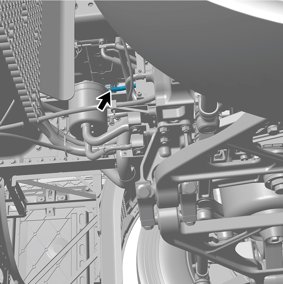
(including PTC) - front left.
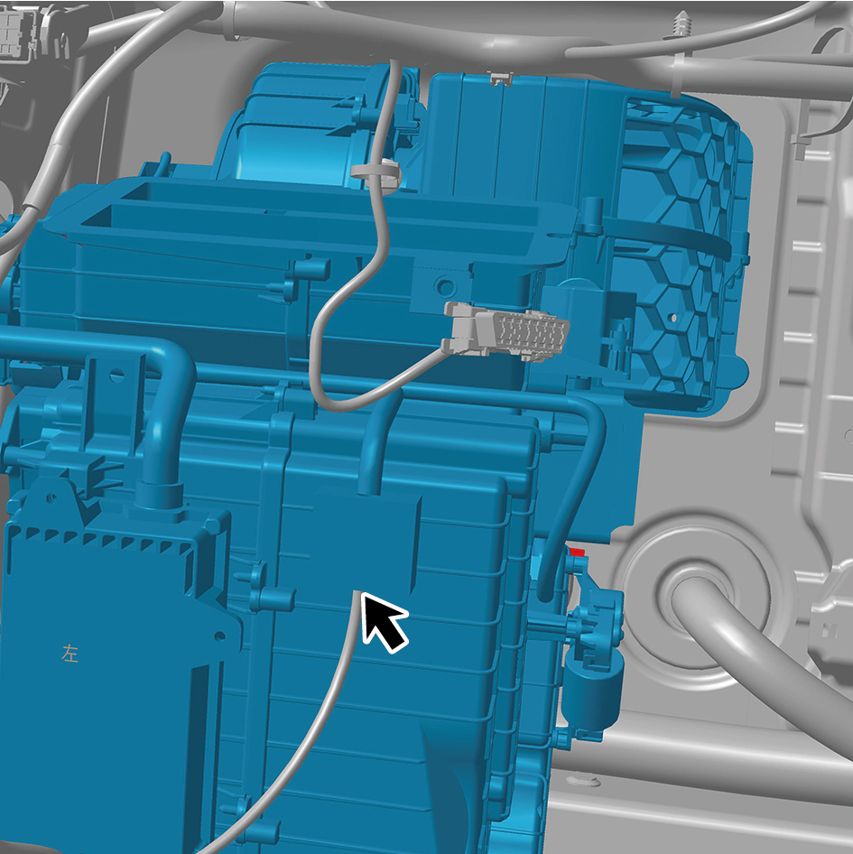
59
Disengage 2 clips of the HVAC assembly (including PTC)
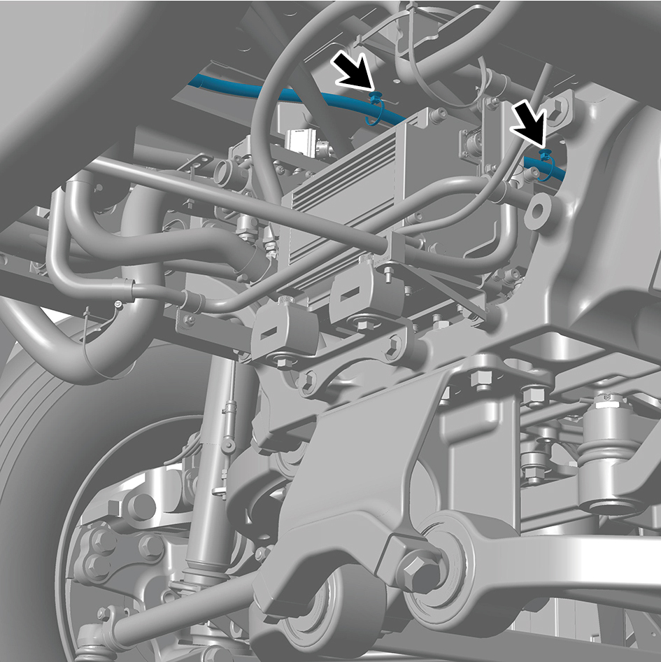
- front left.
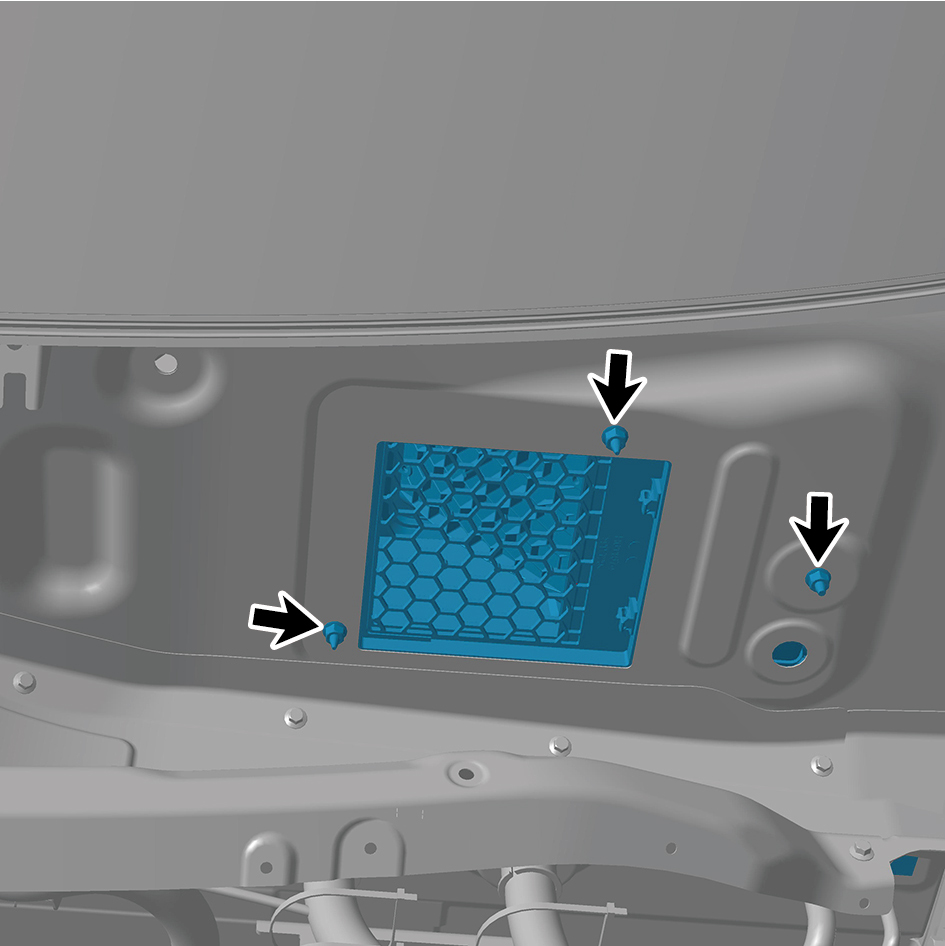
60
Remove 3 fixing nuts of the HVAC assembly (including
PTC) - front left.
61
Remove 2 fixing bolts of the HVAC assembly (including
PTC) - front left.
62
Disconnect the A/C pipeline.
63
Remove 1 fixing bolts of the HVAC assembly (including
PTC) - front left.
64
Remove the HVAC assembly (including PTC) - front left.
Installation Procedures
1
Move the HVAC assembly (including PTC) - front left to
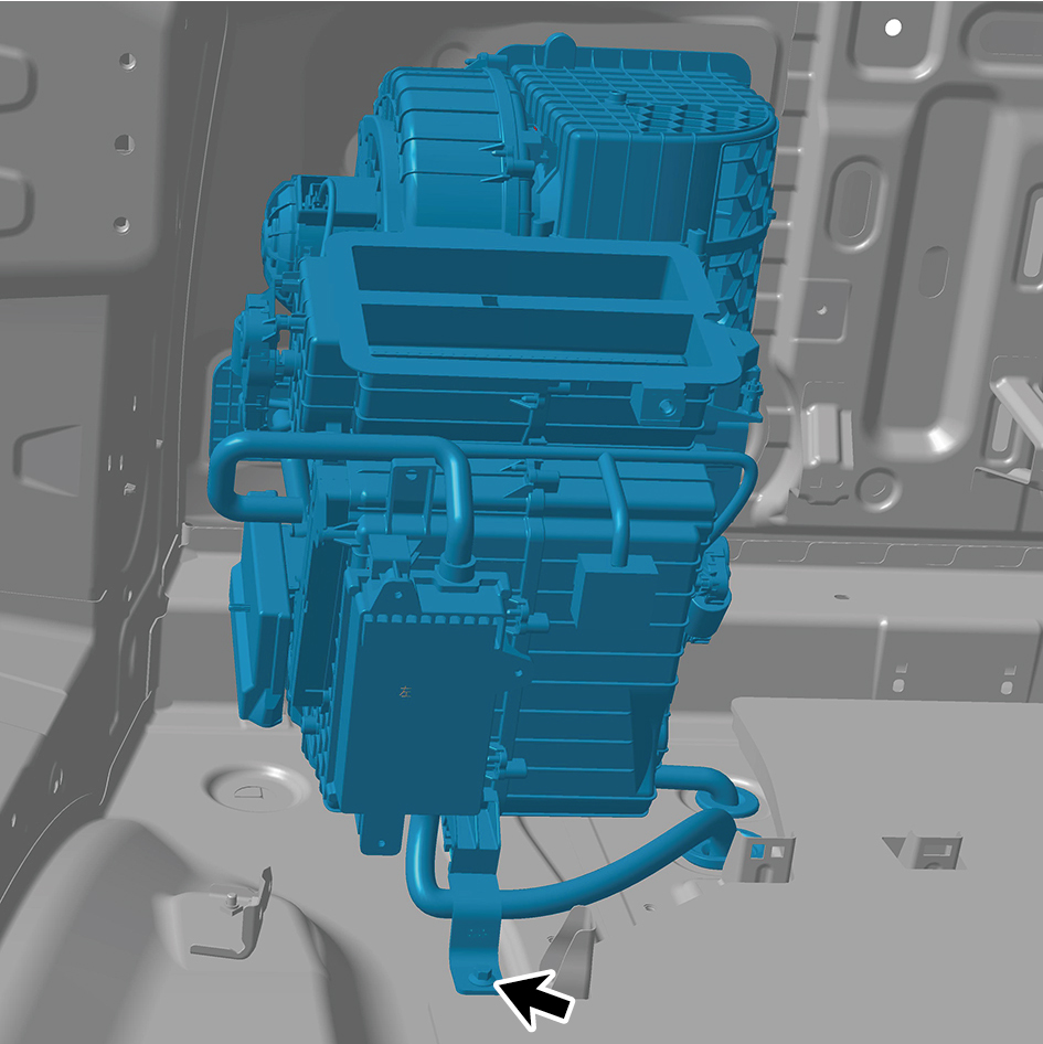
the mounting position.
2
Install 1 fixing bolt of the HVAC assembly (including PTC)
- front left.
Torque: (7.5 +/- .75) ft lbs
3
Connect the A/C pipeline.
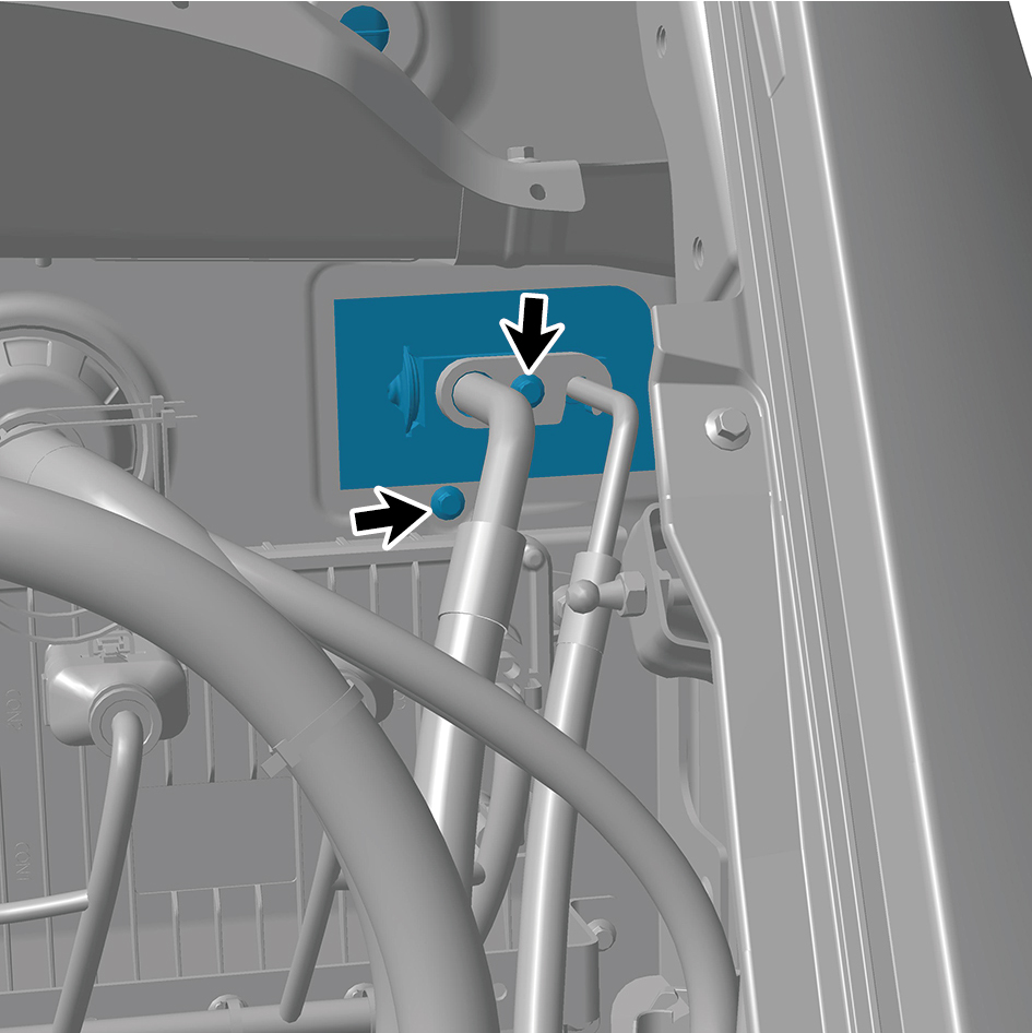
4
Install 2 fixing bolt of the HVAC assembly (including PTC)
- front left.
Torque: (7.5 +/- .75) ft lbs
5
Install 3 fixing nuts of the HVAC assembly (including PTC)
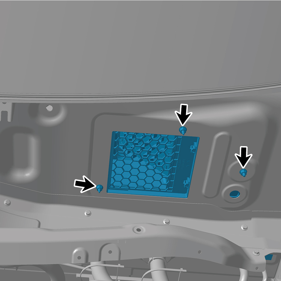
- front left.
Torque: (7.5 +/- .75) ft lbs
6
Install 2 clips of the HVAC assembly (including PTC) -
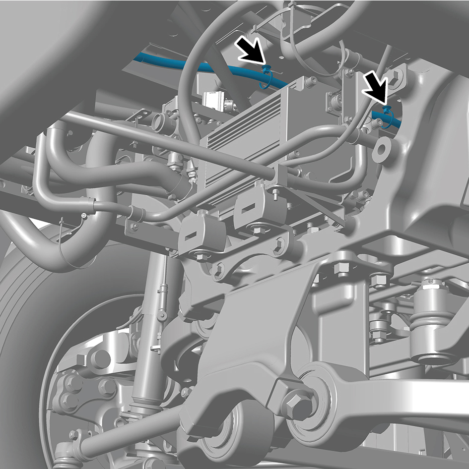
front left.
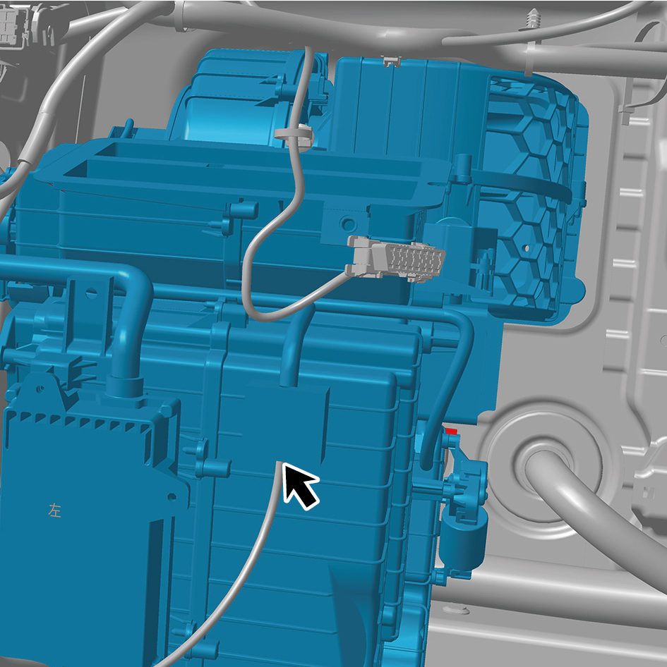
7
Connect 2 harness connectors of the HVAC assembly
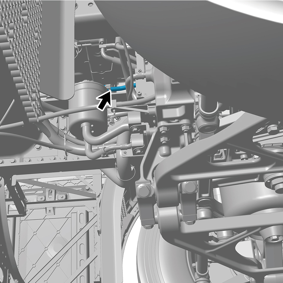
(including PTC) - front left.
caution
The harness is firmly connected following the
principal of "insert until a click is heard for
confirmation".
8
Install the side blowing air duct assy-lh.
9
Install the cross car beam assy.
10
Install the cross car beam pole.
11
Install the controller bracket assy.
12
Install the body domain control unit.
13
Install the EBS bracket.
14
Install the EBS controller assy.
15
Install the Tbox-gw bracket.
16
Install the Tbox-gw.
17
Install the cockpit domain controller bracket.
18
Install the cockpit domain controller.
19
Install the smart appliance box.
20
Install the fixing bracket-lh.
21
Install the AR-HUD.
22
Install the ontology assy under the dashboard.
23
Install the cover assy-defrost frt.
24
Install the decorative plate assy-dashboard-rh frt.
25
Install the lor trim assy-dashboard-rh frt.
26
Install the trim assy-dashboard-lh frt.
27
Install the ontology assy on the dashboard.
28
Install the air vent decorative plate assy-rh.
29
Install the storage box assy-rh.
30
Install the lower switch panel assy-rh.
31
Install the switch panel assy-rh.
32
Install the cover assy-dashboard-rh frt.
33
Install the front side enclosure assy-rh.
34
Install the assembly of the cover assy-steering under
column guard.
35
Install the air vent decorative plate assy-lh.
36
Install the instrument panel trim panel assy- upper lh.
37
Install the vehicle travelling data recorder.
38
Install the switch panel lower trim assy-lh.
39
Install the trim assy on the switch panel-lh.
40
Install the cover assy-dashboard-lh frt.
41
Install the front side enclosure assy-lh.
42
Install the assembly of the instrument panel trim panel
assy- lowerr lh.
43
Install the a-pillar guard assy-rh.
44
Install the a-pillar guard assy-lh.
45
Install the base-rh display brkt.
46
Install the camera monitor screen-rh.
47
Install the upr cover- rh camera brkt.
48
Install the base-lh display brkt.
49
Install the camera monitor screen.
50
Install the upr cover- lh camera brkt.
51
Install the IPC screen.
52
Install the CAR screen.
53
Install the IVI screen.
54
Install the ip brim assy.
55
Install the cover-combination switch-lor.
56
Install the steering wheel assy.
57
Install the dab decorative cove.
58
Install the assembly of the front windshield cover.
59
Install the wiper arm assy.
60
Fill with A/C refrigerant.
61
Perform power-on of the high voltage system.
62
Connect the battery negative cable.
63
Close the front flip cover plate.
64
Close the door.
7.1.6.2 Replacement of HVAC Assembly (including PTC) - front Right
(including PTC) - front Right
Removal Procedures
1
Open the door.
2
Open the front flip cover plate.
3
Disconnect the battery negative cable.
4
Perform power-off of high voltage system.
5
Recycle A/C refrigerant.
6
Remove the wiper arm assy.
7
Remove the assembly of the front windshield cover.
8
Remove the dab decorative cove.
9
Remove the steering wheel assy.
10
Remove the cover-combination switch-lor.
11
Remove the ip brim assy.
12
Remove the IVI screen.
13
Remove the CAR screen.
14
Remove the IPC screen.
15
Remove the upr cover- lh camera brkt.
16
Remove the camera monitor screen.
17
Remove the base-lh display brkt.
18
Remove the upr cover- rh camera brkt.
19
Remove the camera monitor screen-rh.
20
Remove the base-rh display brkt.
21
Remove the a-pillar guard assy-lh.
22
Remove the a-pillar guard assy-rh.
23
Remove the assembly of the instrument panel trim panel
assy- lowerr lh.
24
Remove the front side enclosure assy-lh.
25
Remove the cover assy-dashboard-lh frt.
26
Remove the trim assy on the switch panel-lh.
27
Remove the switch panel lower trim assy-lh.
28
Remove the vehicle travelling data recorder.
29
Remove the instrument panel trim panel assy- upper lh.
30
Remove the air vent decorative plate assy-lh.
31
Remove the assembly of the cover assy-steering under
column guard.
32
Remove the front side enclosure assy-rh.
33
Remove the cover assy-dashboard-rh frt.
34
Remove the switch panel assy-rh.
35
Remove the lower switch panel assy-rh.
36
Remove the storage box assy-rh.
37
Remove the air vent decorative plate assy-rh.
38
Remove the ontology assy on the dashboard.
39
Remove the trim assy-dashboard-lh frt.
40
Remove the lor trim assy-dashboard-rh frt.
41
Remove the decorative plate assy-dashboard-rh frt.
42
Remove the cover assy-defrost frt.
43
Remove the ontology assy under the dashboard.
44
Remove the AR-HUD.
45
Remove the fixing bracket-lh.
46
Remove the smart appliance box.
47
Remove the cockpit domain controller.
48
Remove the cockpit domain controller bracket.
49
Remove the Tbox-gw.
50
Remove the Tbox-gw bracket.
51
Remove the EBS controller assy.
52
Remove the EBS bracket.
53
Remove the body domain control unit.
54
Remove the controller bracket assy.
55
Remove the cross car beam pole.
56
Remove the cross car beam assy.
57
Remove the blowing air duct assy-rh.
58
Remove the storage box bracket assy.
59
Disconnect 2 harness connectors of the HVAC assembly
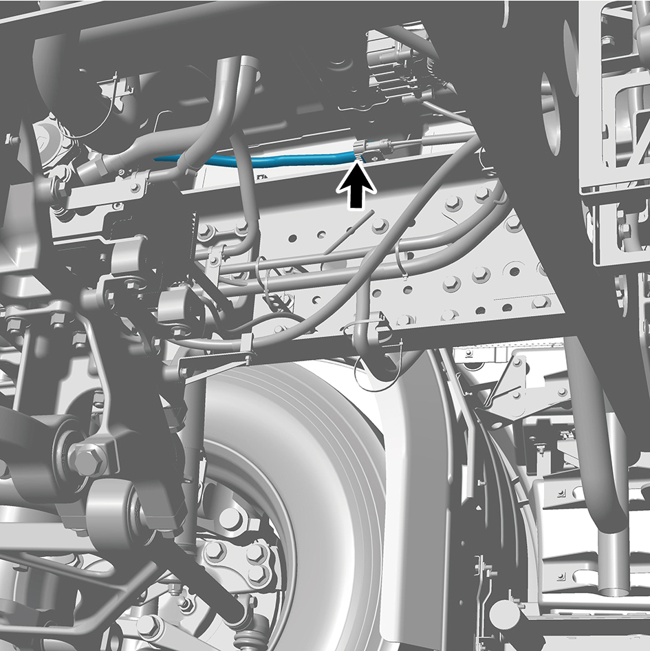
(including PTC) - front right.
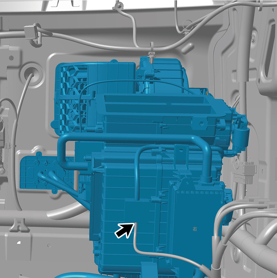
60
Disengage 2 clips of the HVAC assembly (including PTC)
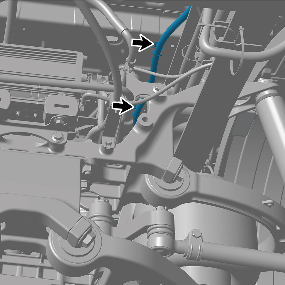
- front right.
61
Remove 3 fixing nuts of the HVAC assembly (including
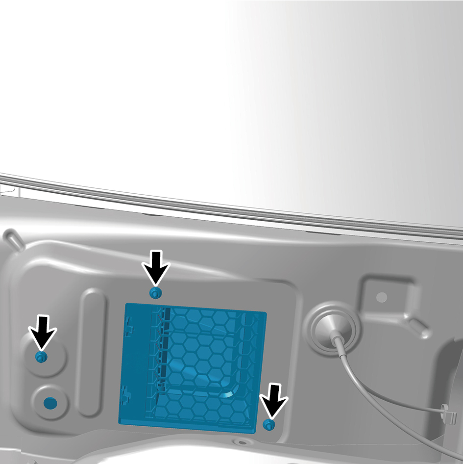
PTC) - front right.
62
Remove 3 fixing bolts of the HVAC assembly (including
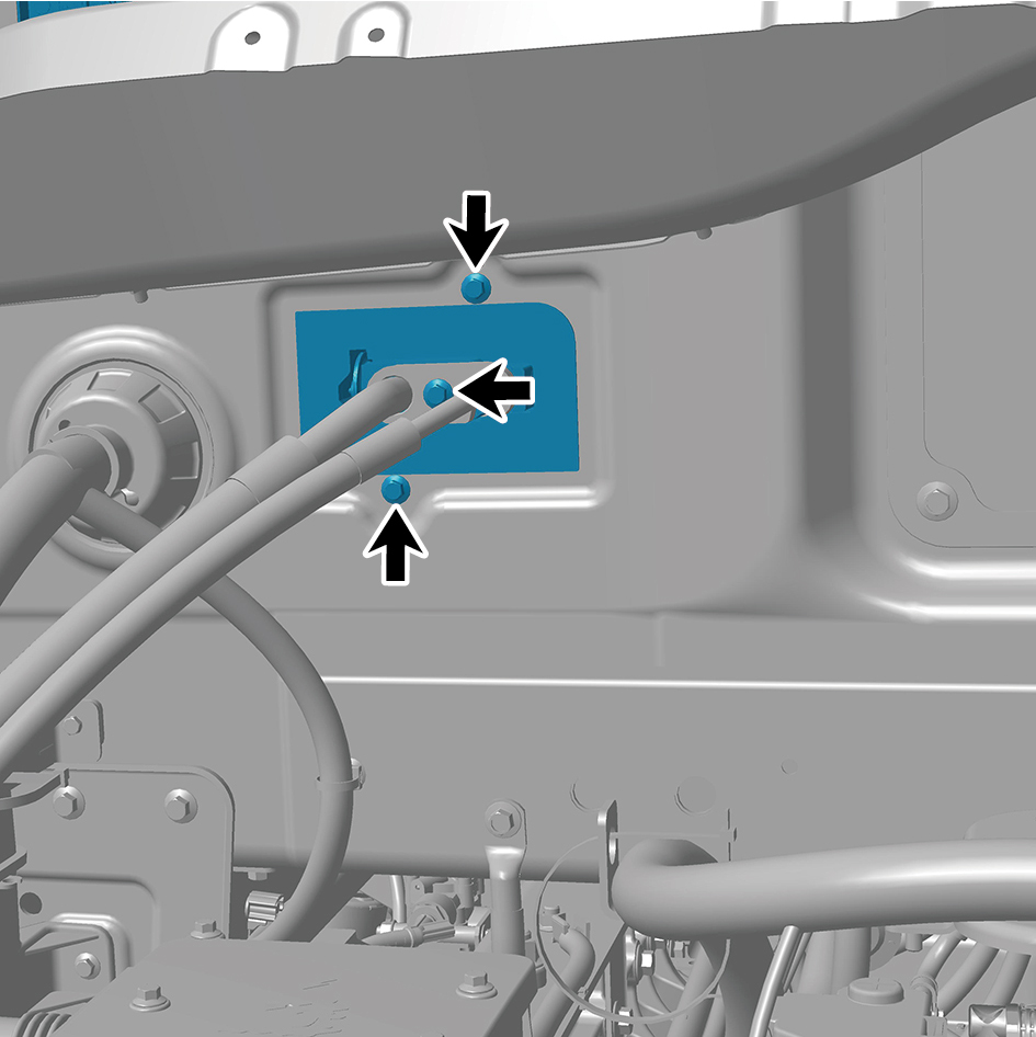
PTC) - front right.
63
Disconnect the A/C pipeline.
64
Remove 1 fixing bolts of the HVAC assembly (including
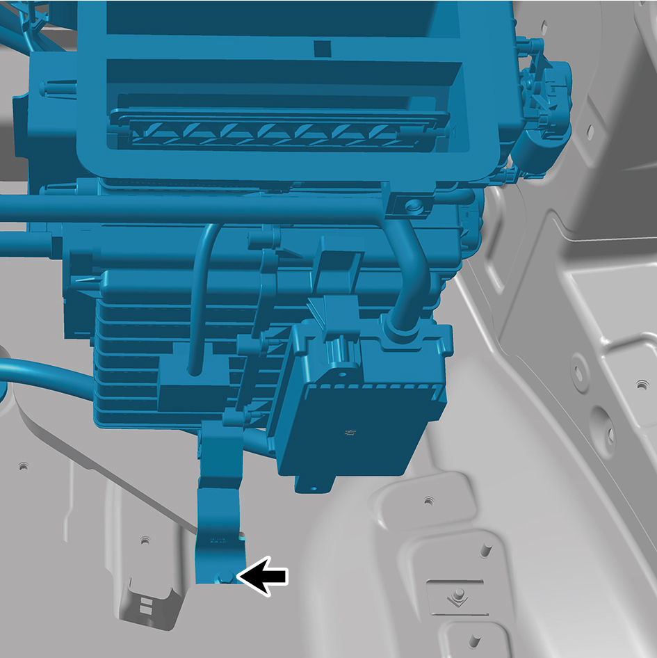
PTC) - front right.
65
Remove the HVAC assembly (including PTC) - front right.
Installation Procedures
1
Move the HVAC assembly (including PTC) - front right to
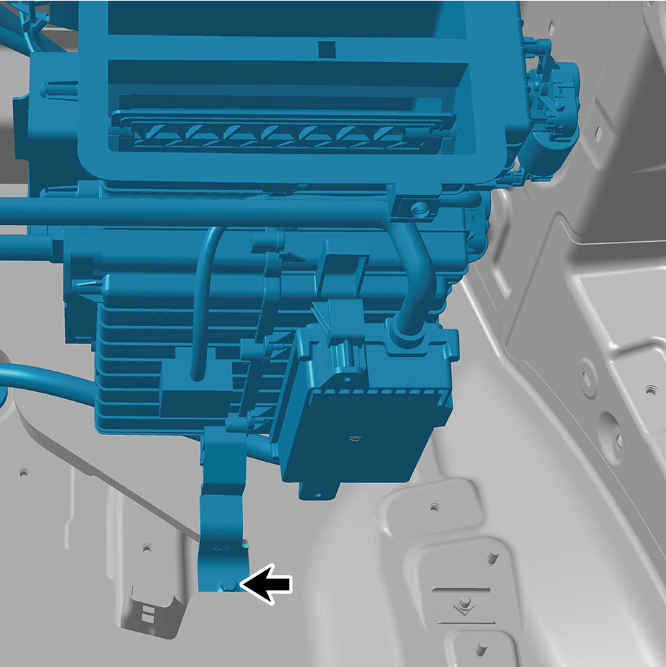
the mounting position.
2
Install 1 fixing bolt of the HVAC assembly (including PTC)
- front right.
Torque: (7.5 +/- .75) ft lbs
3
Connect the A/C pipeline.
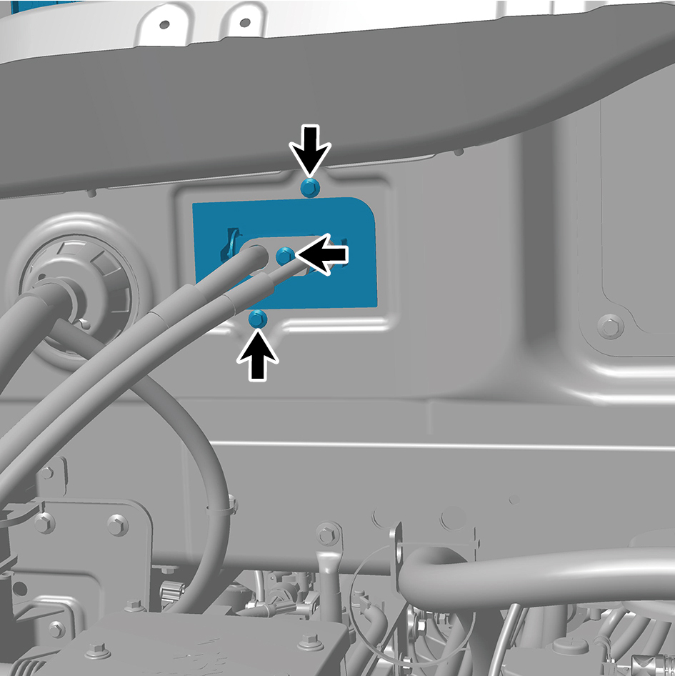
4
Install 3 fixing bolt of the HVAC assembly (including PTC)
- front right.
Torque: (7.5 +/- .75) ft lbs
5
Install 3 fixing nuts of the HVAC assembly (including PTC)
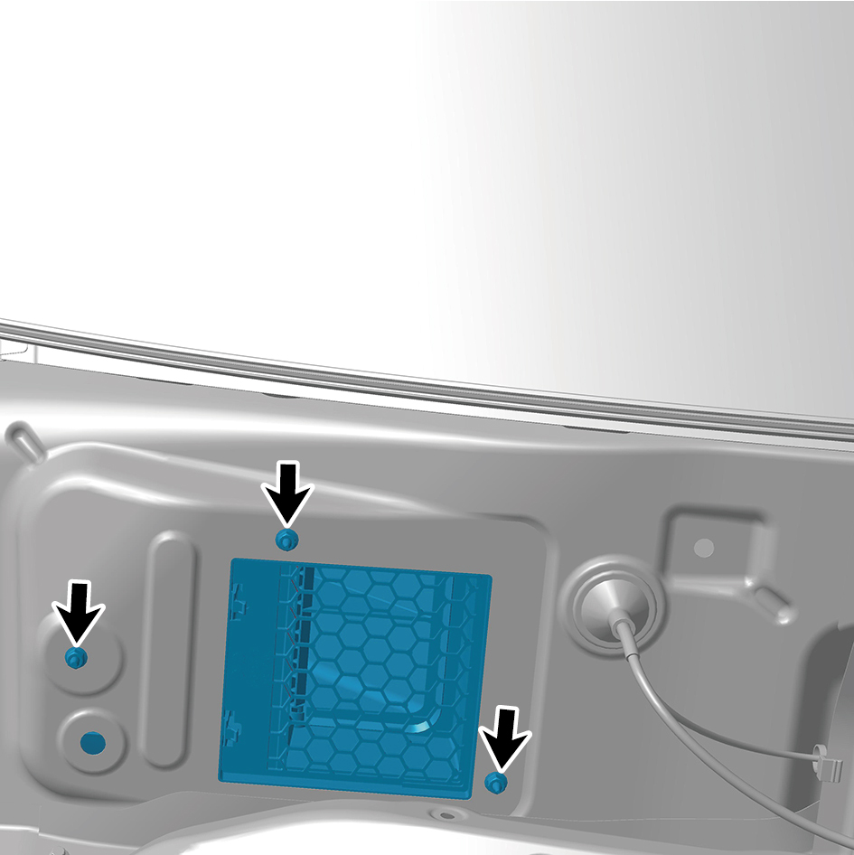
- front right.
Torque: (7.5 +/- .75) ft lbs
6
Connect 2 clips of the HVAC assembly (including PTC) -
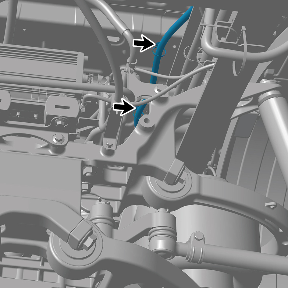
front right.
7
Connect 2 harness connectors of the HVAC assembly
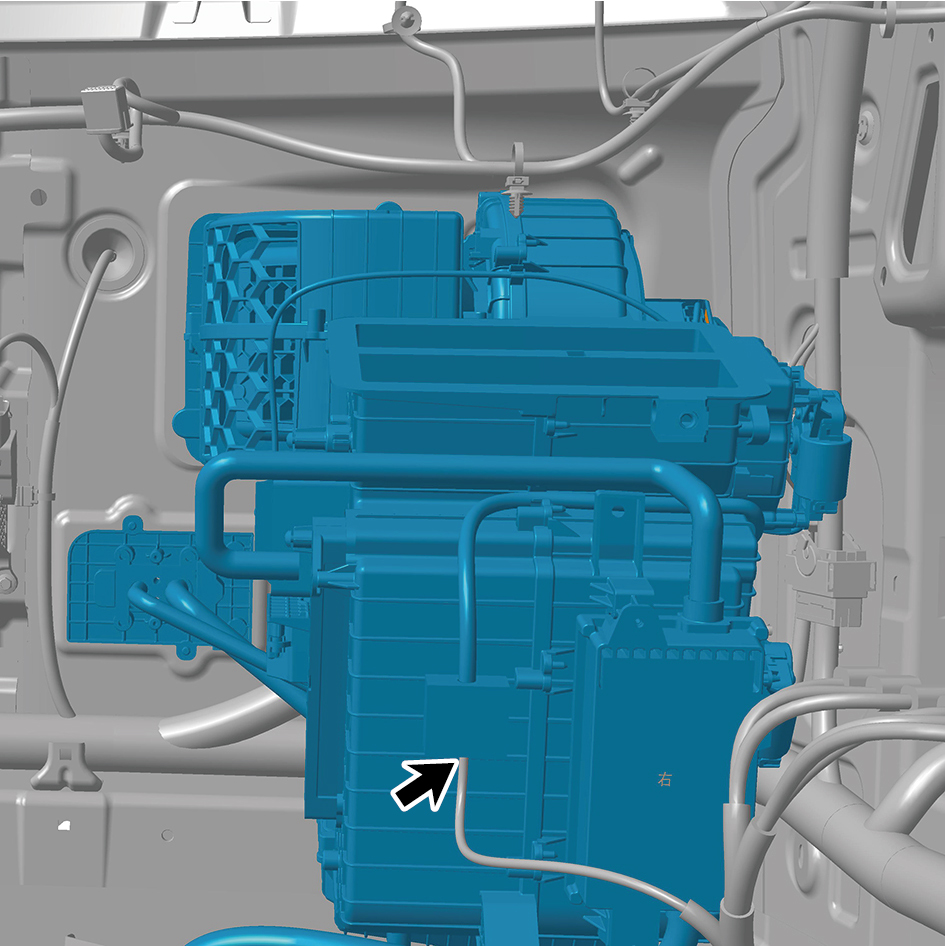
(including PTC) - front right.
caution
The harness is firmly connected following the
principal of "insert until a click is heard for
confirmation".
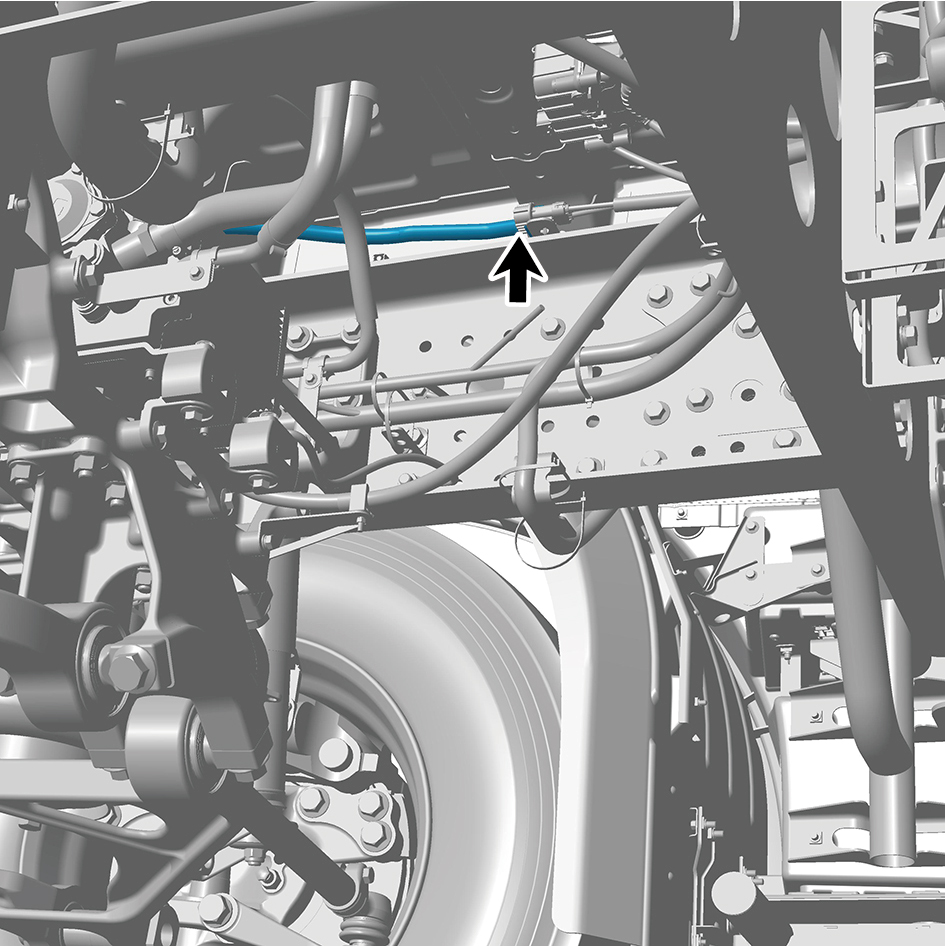
8
Install the storage box bracket assy.
9
Install the blowing air duct assy-rh.
10
Install the cross car beam assy.
11
Install the cross car beam pole.
12
Install the controller bracket assy.
13
Install the body domain control unit.
14
Install the EBS bracket.
15
Install the EBS controller assy.
16
Install the Tbox-gw bracket.
17
Install the Tbox-gw.
18
Install the cockpit domain controller bracket.
19
Install the cockpit domain controller.
20
Install the smart appliance box.
21
Install the fixing bracket-lh.
22
Install the AR-HUD.
23
Install the ontology assy under the dashboard.
24
Install the cover assy-defrost frt.
25
Install the decorative plate assy-dashboard-rh frt.
26
Install the lor trim assy-dashboard-rh frt.
27
Install the trim assy-dashboard-lh frt.
28
Install the ontology assy on the dashboard.
29
Install the air vent decorative plate assy-rh.
30
Install the storage box assy-rh.
31
Install the lower switch panel assy-rh.
32
Install the switch panel assy-rh.
33
Install the cover assy-dashboard-rh frt.
34
Install the front side enclosure assy-rh.
35
Install the assembly of the cover assy-steering under
column guard.
36
Install the air vent decorative plate assy-lh.
37
Install the instrument panel trim panel assy- upper lh.
38
Install the vehicle travelling data recorder.
39
Install the switch panel lower trim assy-lh.
40
Install the trim assy on the switch panel-lh.
41
Install the cover assy-dashboard-lh frt.
42
Install the front side enclosure assy-lh.
43
Install the assembly of the instrument panel trim panel
assy- lowerr lh.
44
Install the a-pillar guard assy-rh.
45
Install the a-pillar guard assy-lh.
46
Install the base-rh display brkt.
47
Install the camera monitor screen-rh.
48
Install the upr cover- rh camera brkt.
49
Install the base-lh display brkt.
50
Install the camera monitor screen.
51
Install the upr cover- lh camera brkt.
52
Install the IPC screen.
53
Install the CAR screen.
54
Install the IVI screen.
55
Install the ip brim assy.
56
Install the cover-combination switch-lor.
57
Install the steering wheel assy.
58
Install the dab decorative cove.
59
Install the assembly of the front windshield cover.
60
Install the wiper arm assy.
61
Fill with A/C refrigerant.
62
Perform power-on of the high voltage system.
63
Connect the battery negative cable.
64
Close the front flip cover plate.
65
Close the door.
7.1.6.3 Replacement of HVAC Assembly (including PTC) - Rear
(including PTC) - Rear
Removal Procedures
1
Open the door.
2
Open the front flip cover plate.
3
Disconnect the battery negative cable.
4
Perform power-off of high voltage system.
5
Recycle A/C refrigerant.
6
Remove the rear A/C lower air duct.
7
Remove the middle drawer assembly.
8
Remove the fire extinguisher.
9
Remove the IP left upper trim panel assembly.
10
Remove the front USB interface.
11
Remove the IP left access cover plate assembly.
12
Remove the left switch panel assembly.
13
Remove the left switch panel lower trim panel assembly.
14
Remove the IP left lower trim panel assembly.
15
Remove the left middle side wall lower trim panel
assembly.
16
Remove the left middle side wall middle trim panel
assembly.
caution
1.First remove the break glass hammer's zipper
cover, carefully take out the break glass hammer's
pull ring and place it inside the trim panel.
2.Be careful to avoid accidentally pulling the break
glass hammer's pull ring.
17
Remove the toolbox left trim panel assembly.
18
Remove the 120V receptacle.
19
Remove the vehicle power supply (12V).
20
Remove the interior temperature sensor (rear).
21
Remove the toolbox trim panel assembly.
22
Disconnect 1 harness connector of the HVAC assembly
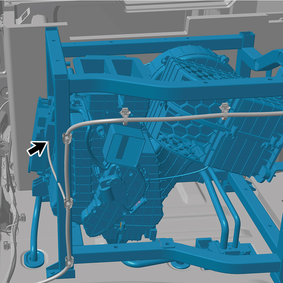
(including PTC) - rear.
23
Disengage 1 fixing clip of the HVAC assembly (including
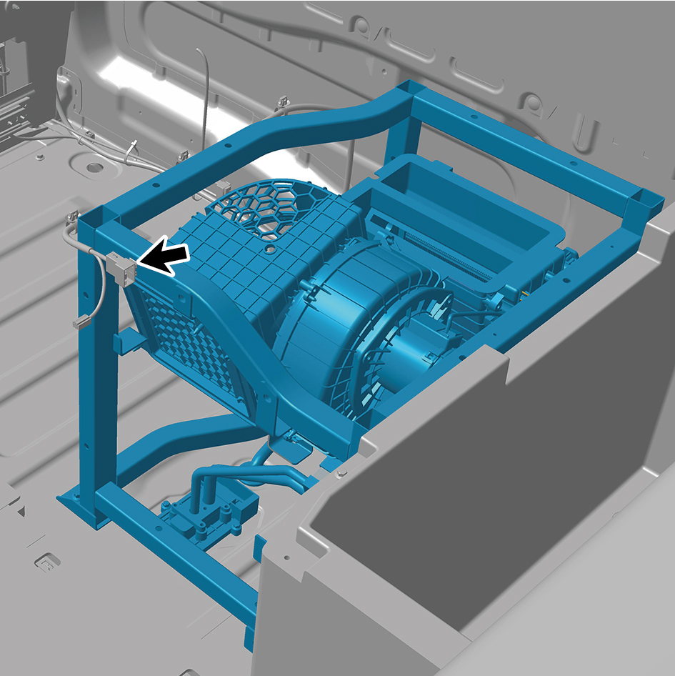
PTC) - rear.
24
Remove 2 fixing bolts of the HVAC assembly (including
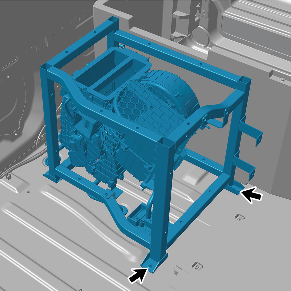
PTC) - rear.
25
Remove 4 fixing bolts of the HVAC assembly (including
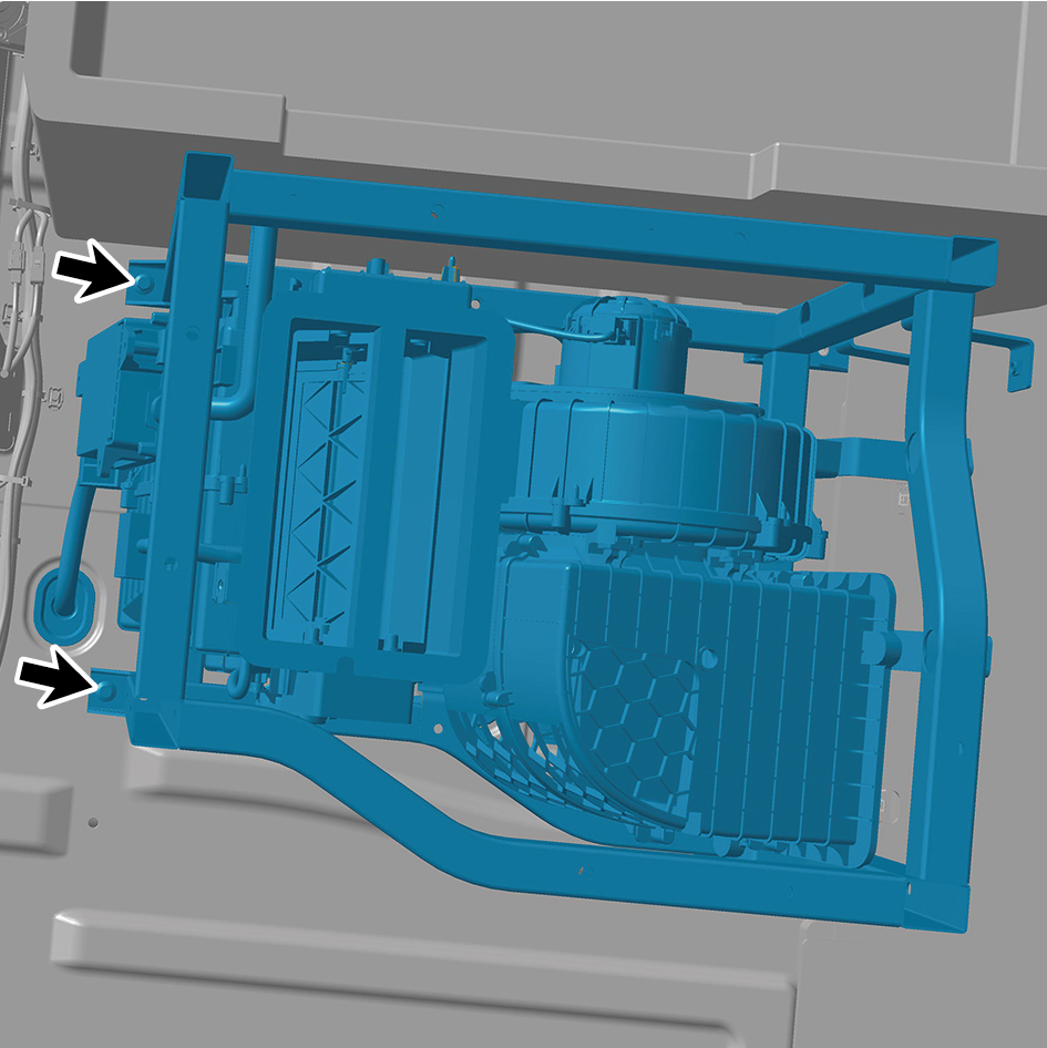
PTC) - rear.
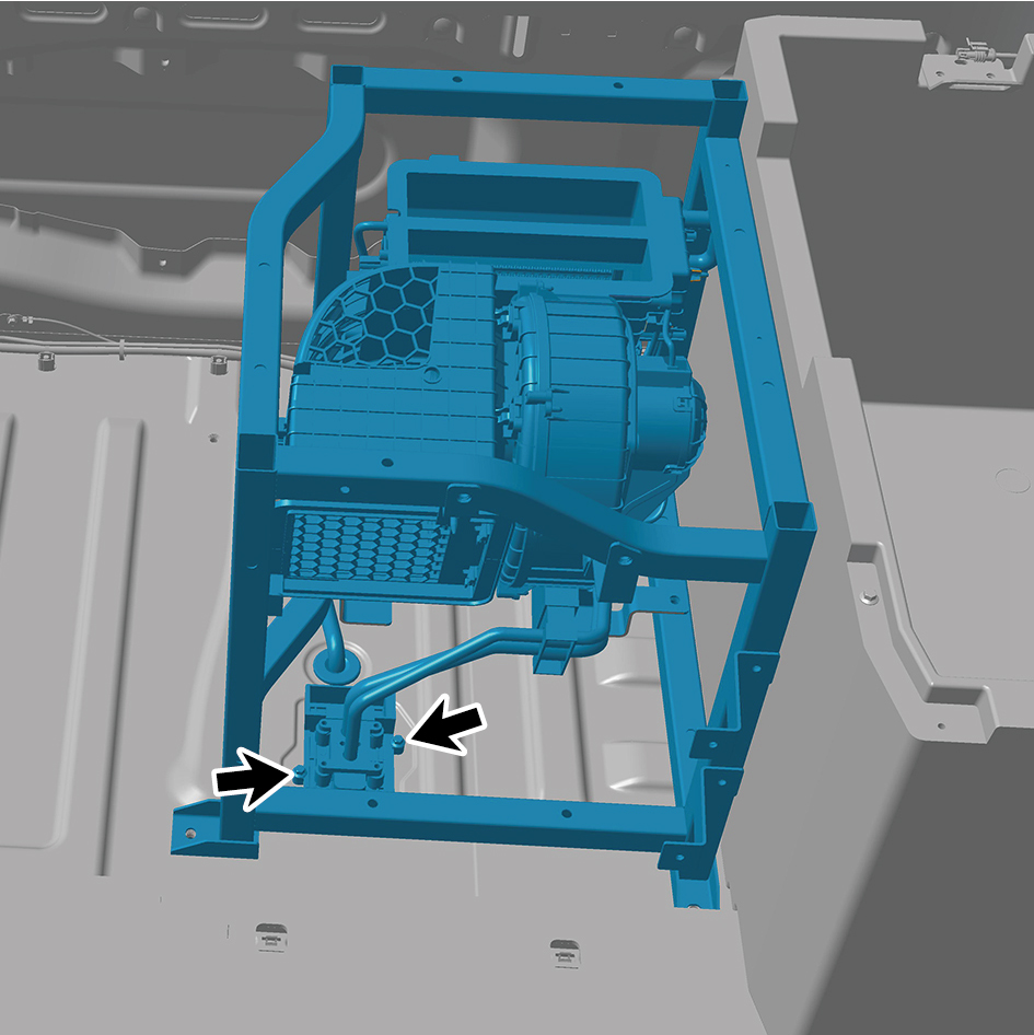
26
Pull out the harness, and disconnect 1 harness connector
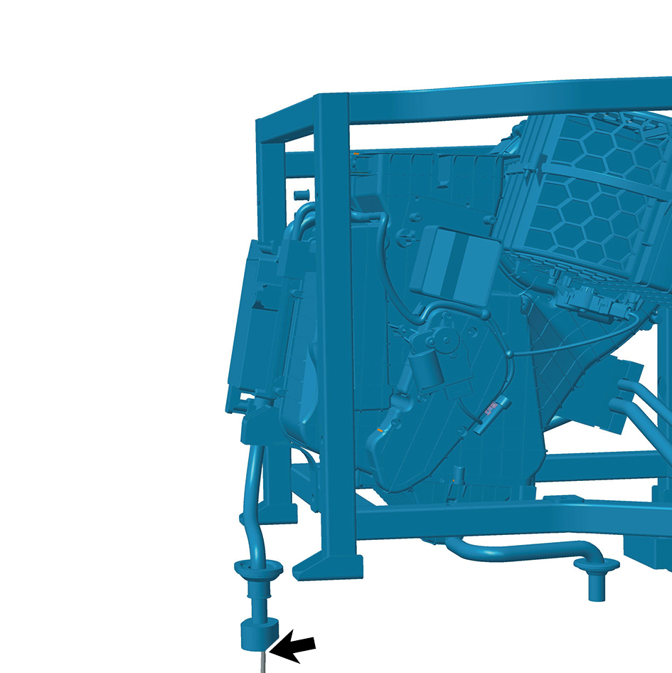
of the HVAC assembly (including PTC) - rear.
27
After flipping the HVAC assembly (including PTC) - rear,
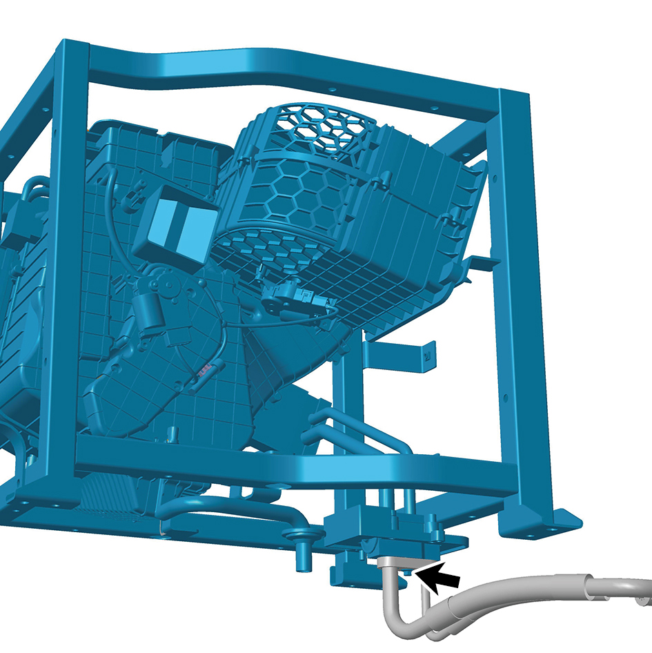
remove 1 fixing bolt of the HVAC assembly (including
PTC) - rear.
28
Remove the HVAC assembly (including PTC) - rear.
Installation Procedures
1
Move the HVAC assembly (including PTC) - rear to the
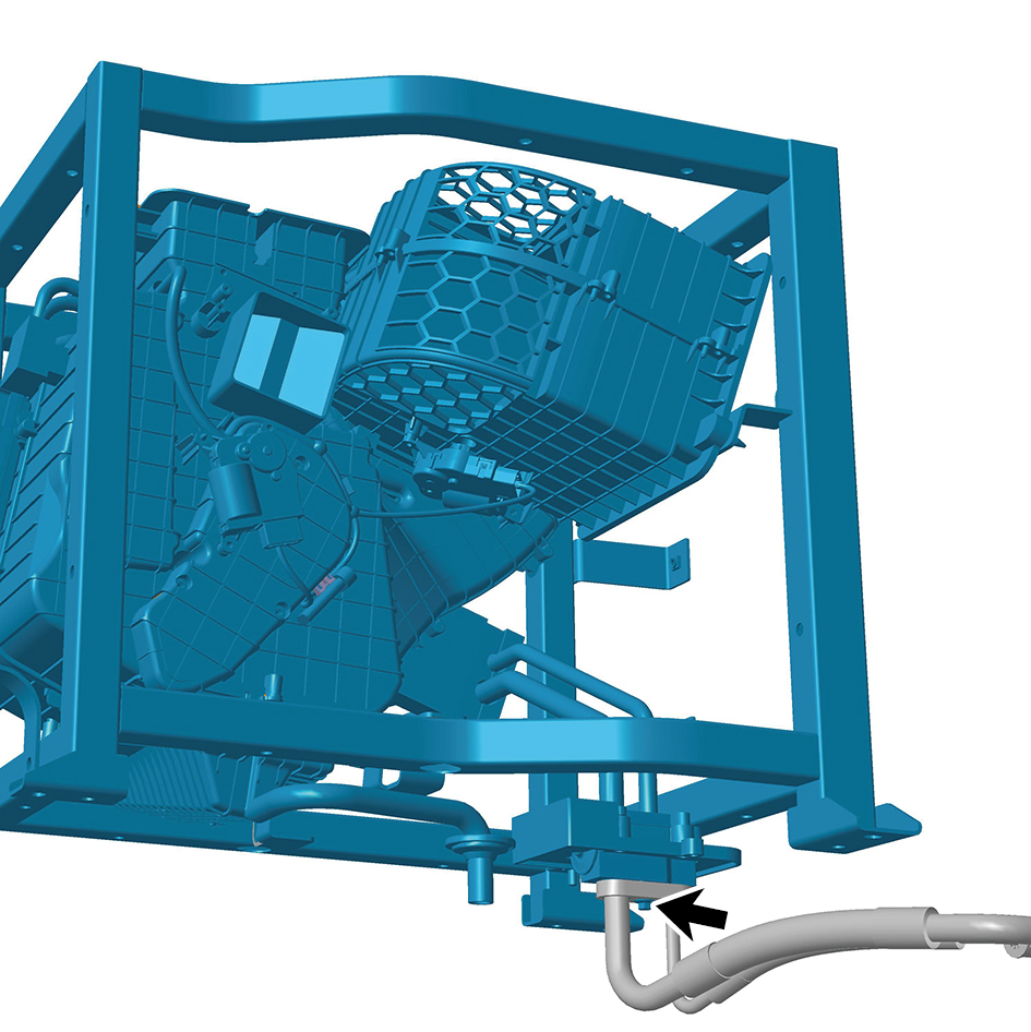
mounting position.
2
Install 1 fixing bolt of the HVAC assembly (including PTC)
- rear.
Torque:(7.5 +/- .75) ft lbs
3
Connect 1 harness connector of the HVAC assembly
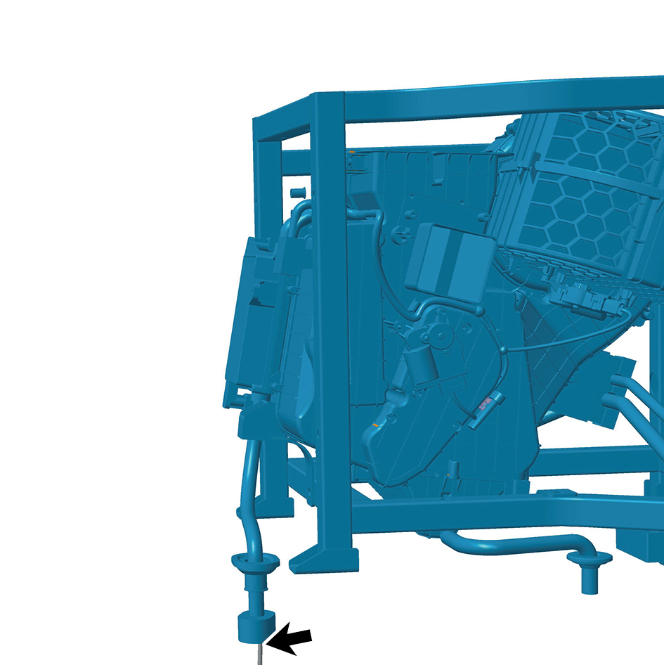
(including PTC) - rear.
caution
The harness is firmly connected following the
principal of "insert until a click is heard for
confirmation".
4
Install 4 fixing bolt of the HVAC assembly (including PTC)
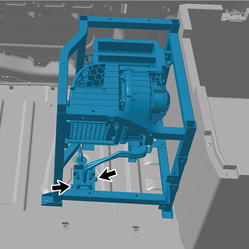
- rear.
Torque:(7.5 +/- .75) ft lbs
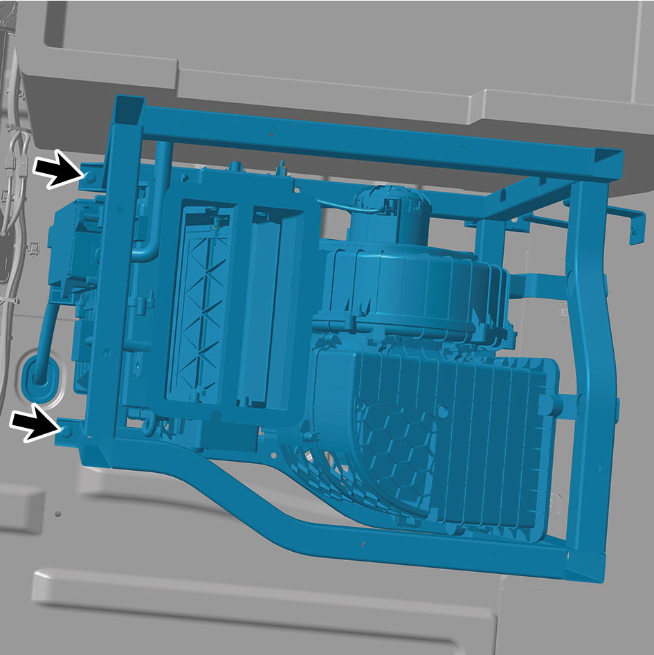
5
Install 2 fixing bolt of the HVAC assembly (including PTC)
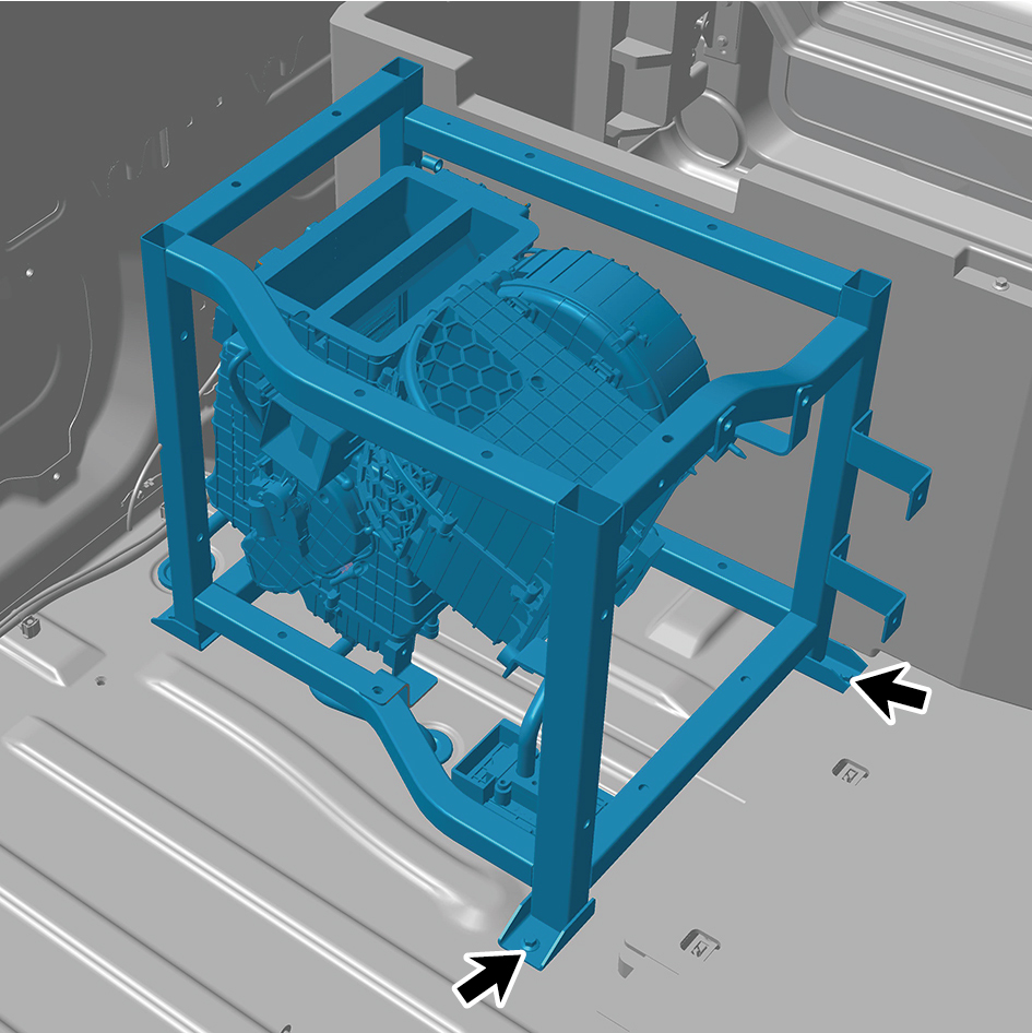
- rear.
Torque:(6.5 +/- .75) ft lbs
6
Install 1 fixing clip of the HVAC assembly (including PTC) -
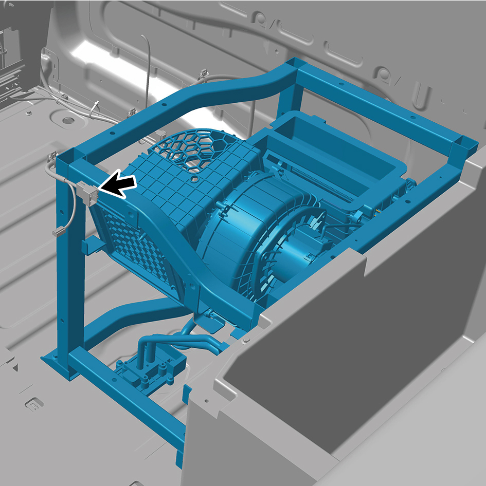
rear.
7
Connect 1 harness connector of the HVAC assembly
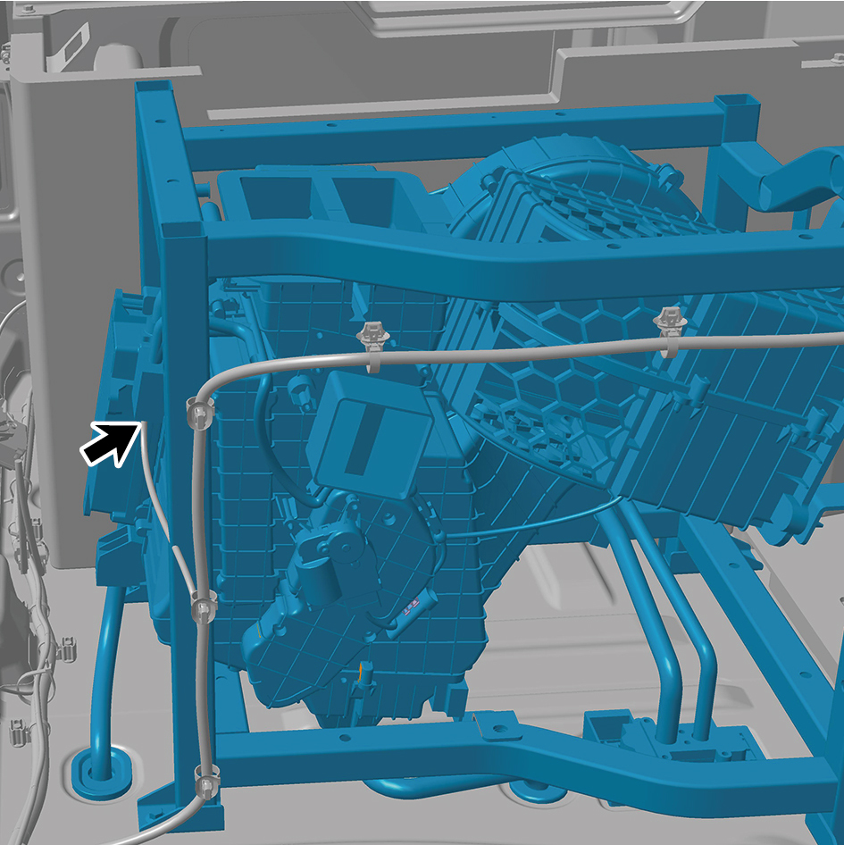
(including PTC) - rear.
caution
The harness is firmly connected following the
principal of "insert until a click is heard for
confirmation".
8
Install the toolbox trim panel assembly.
9
Install the interior temperature sensor (rear).
10
Install the vehicle power supply (12V).
11
Install the 120V receptacle.
12
Install the toolbox left trim panel assembly.
13
Install the left middle side wall middle trim panel assembly.
14
Install the left middle side wall lower trim panel assembly.
15
Install the IP left lower trim panel assembly.
16
Install the left switch panel lower trim panel assembly.
17
Install the left switch panel assembly.
18
Install the IP left access cover plate assembly.
19
Install the front USB interface.
20
Install the IP left upper trim panel assembly.
21
Install the fire extinguisher.
22
Install the middle drawer assembly.
23
Install the rear A/C lower air duct.
24
Fill with A/C refrigerant.
25
Perform power-on of the high voltage system.
26
Connect the battery negative cable.
27
Close the front flip cover plate.
28
Close the door.
7.1.6.4 Replacement of A/C Compressor Assembly
Assembly
Removal Procedures
1
Open the door.
2
Open the front flip cover plate.
3
Disconnect the battery negative cable.
4
Perform power-off of high voltage system.
5
Jack the front end of the vehicle.
6
Drain the transmission hydraulic oil.
7
Remove the left front wheel housing body.
8
Remove the left side wall lower trim panel assembly.
9
Remove the side wall upper mounting bracket assembly
2.
10
Remove the left side wall mounting bracket 1.
11
Remove the left side wall mounting bracket 2.
12
Remove the left side wall lower trim panel mounting frame
assembly.
13
Remove the electric oil pump.
14
Disconnect 2 harness connectors of the A/C compressor
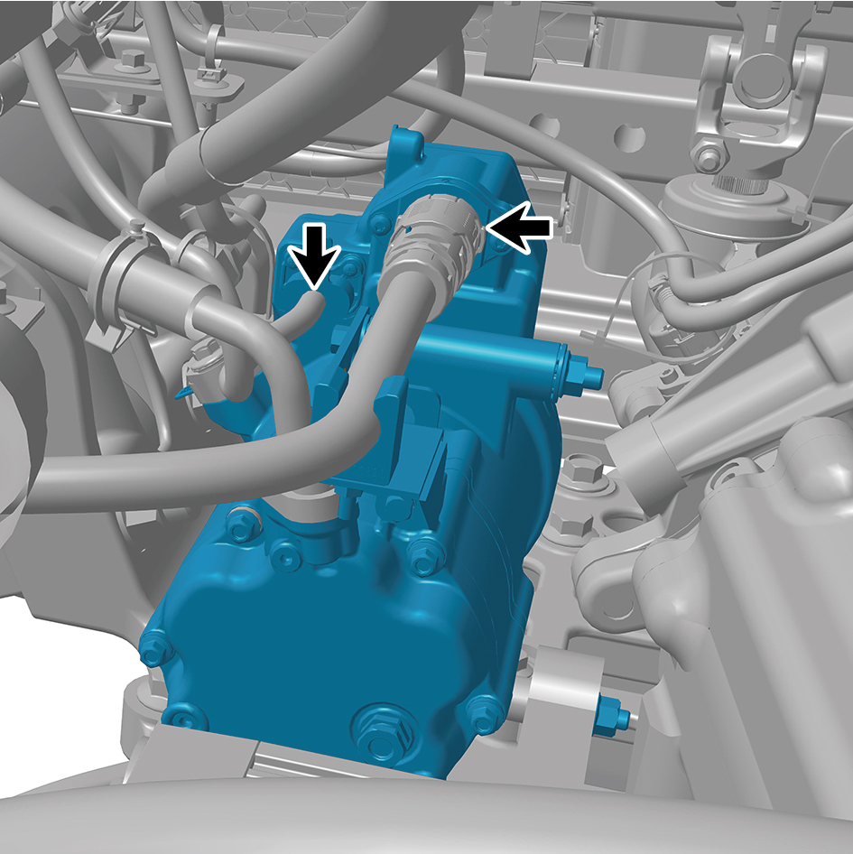
assembly.
15
Remove 1 ground harness fixing bolt of the A/C
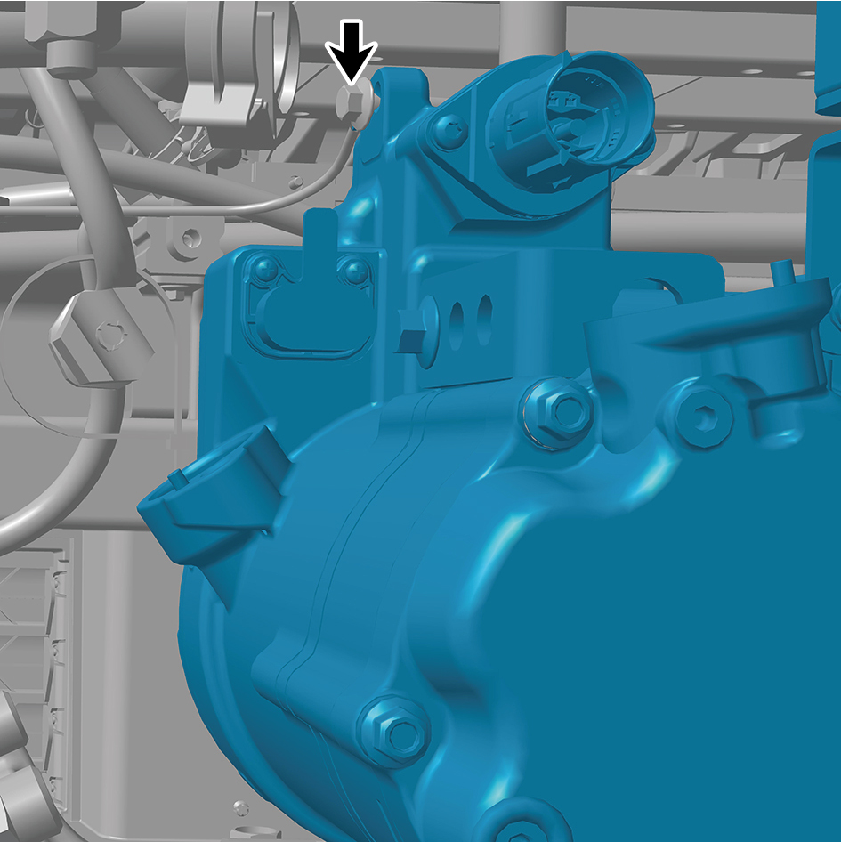
compressor assembly, and detach the ground harness.
16
Remove 2 fixing bolts to disconnect the A/C pipeline from
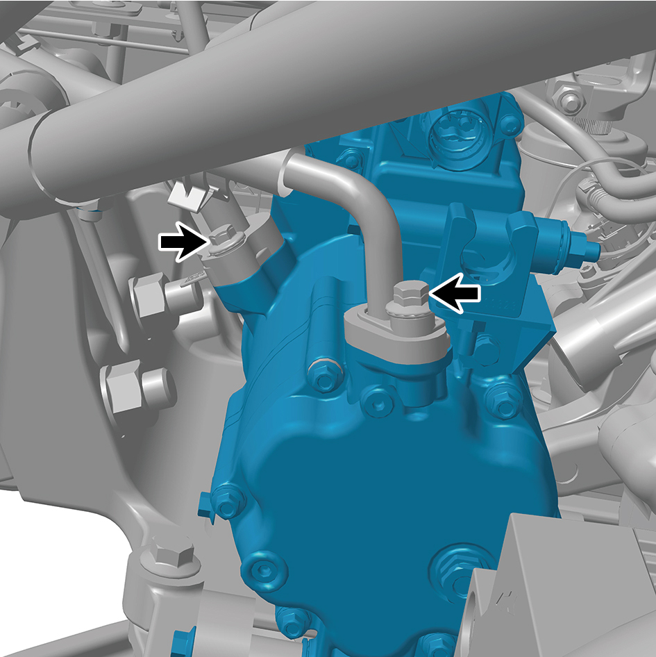
the A/C compressor.
17
Remove 2 fixing bolts of the A/C compressor assembly.
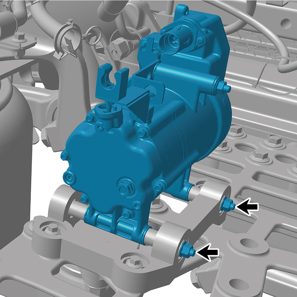
18
Remove the A/C compressor assembly.
caution
Due to the heavy weight of the A/C compressor
assembly, it shall be removed with the help of an
assistant.
Installation Procedures
1
Move the A/C compressor assembly to the mounting
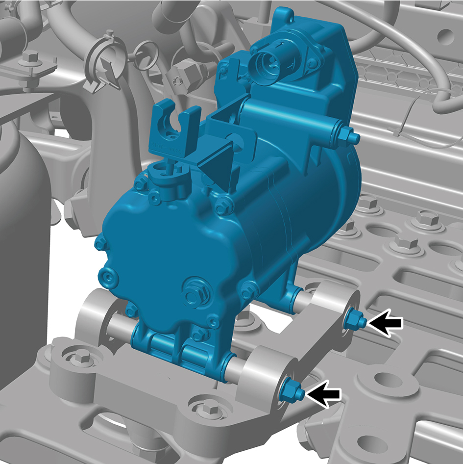
position.
caution
Due to the heavy weight of the A/C compressor
assembly, it shall be moved to the mounting position
with the help of an assistant.
2
Install 2 fixing bolts of the A/C compressor assembly.
Torque: (18.5 +/- 1.5) ft lbs
3
Connect the A/C pipeline to the A/C compressor, and
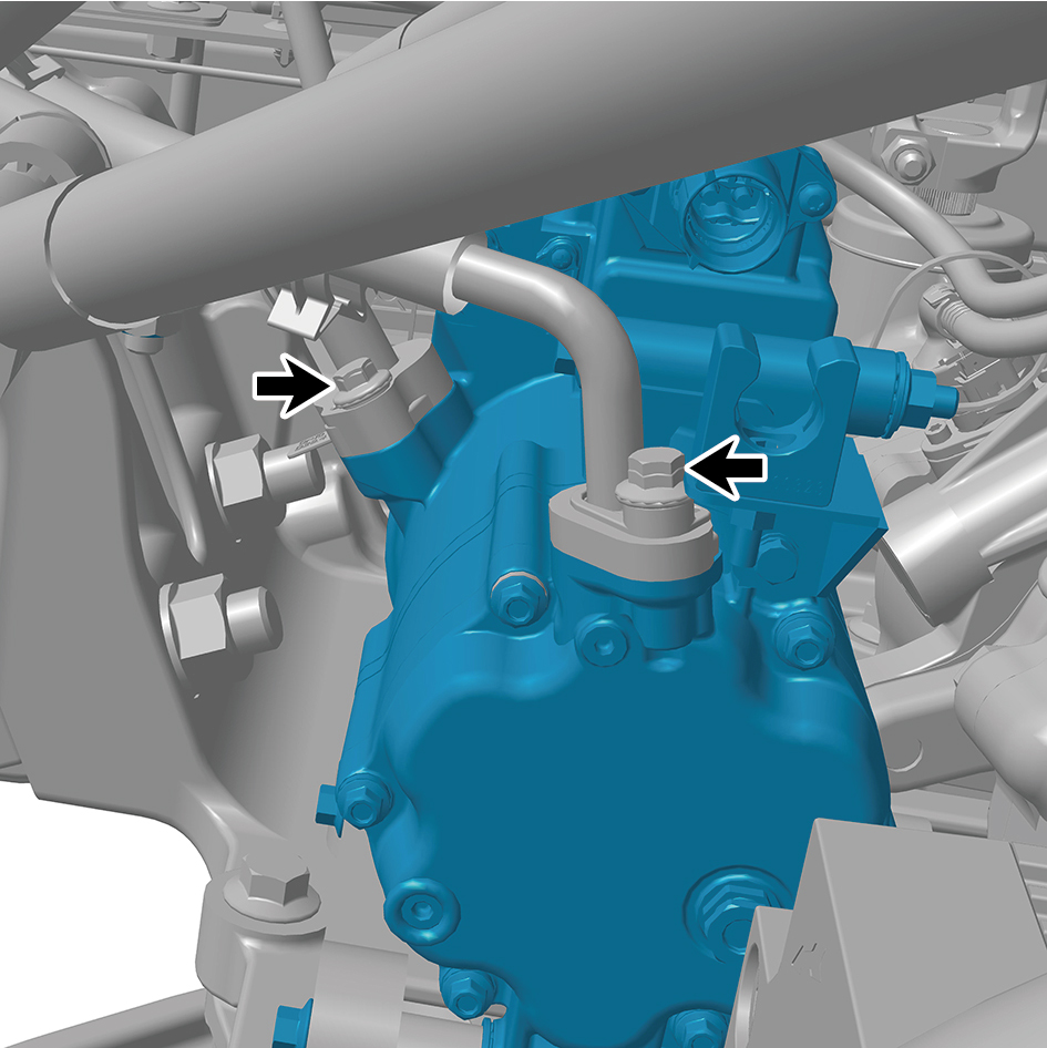
install 2 fixing bolts.
Torque:(18.5 +/- 1.5) ft lbs
4
Connect the ground harness, and install 1 ground harness
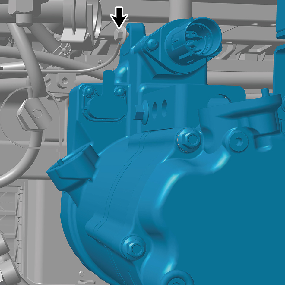
fixing bolt of the A/C compressor assembly.
caution
The harness is firmly connected following the
principal of "insert until a click is heard for
confirmation".
5
Connect 2 harness connectors of the A/C compressor
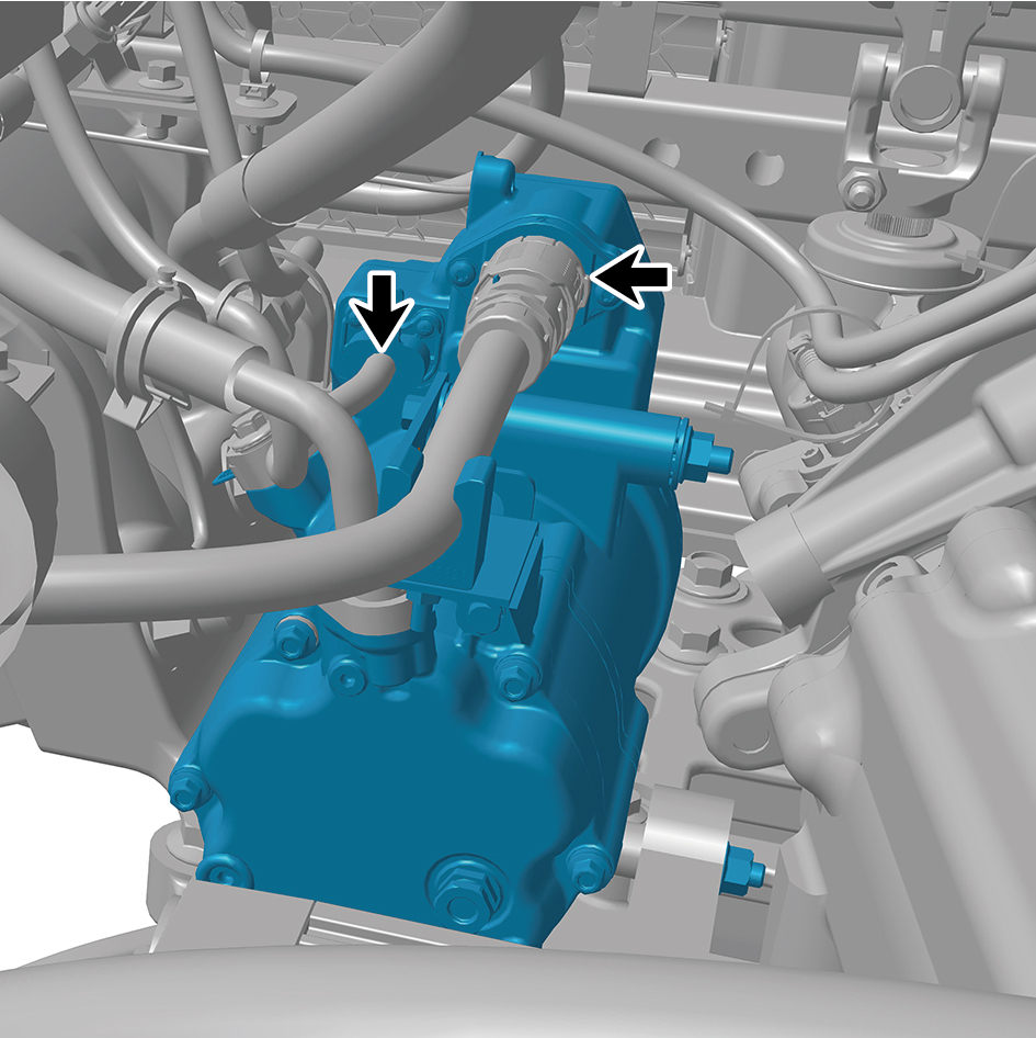
assembly.
caution
The harness is firmly connected following the
principal of "insert until a click is heard for
confirmation".
6
Install the electric oil pump.
7
Install the left side wall lower trim panel mounting frame
assembly.
8
Install the left side wall mounting bracket 2.
9
Install the left side wall mounting bracket 1.
10
Install the side wall upper mounting bracket assembly 2.
11
Install the left side wall lower trim panel assembly.
12
Install the left front wheel housing body.
13
Add the transmission hydraulic oil.
14
Lower the front end of the vehicle.
15
Perform power-on of the high voltage system.
16
Connect the battery negative cable.
17
Close the front flip cover plate.
18
Close the door.
7.1.6.5 Replacement of Exterior Temperature Sensor
Sensor
Removal Procedures
1
Open the door.
2
Open the front flip cover plate.
3
Disconnect the battery negative cable.
caution
power down the high-voltage system before
disconnecting the negative pole of the storage
battery.
4
Remove the primary wiper arm blade assembly (nozzle
and hose).
5
Remove the front windshield cover plate assembly.
6
Disconnect 1 harness connector of the exterior
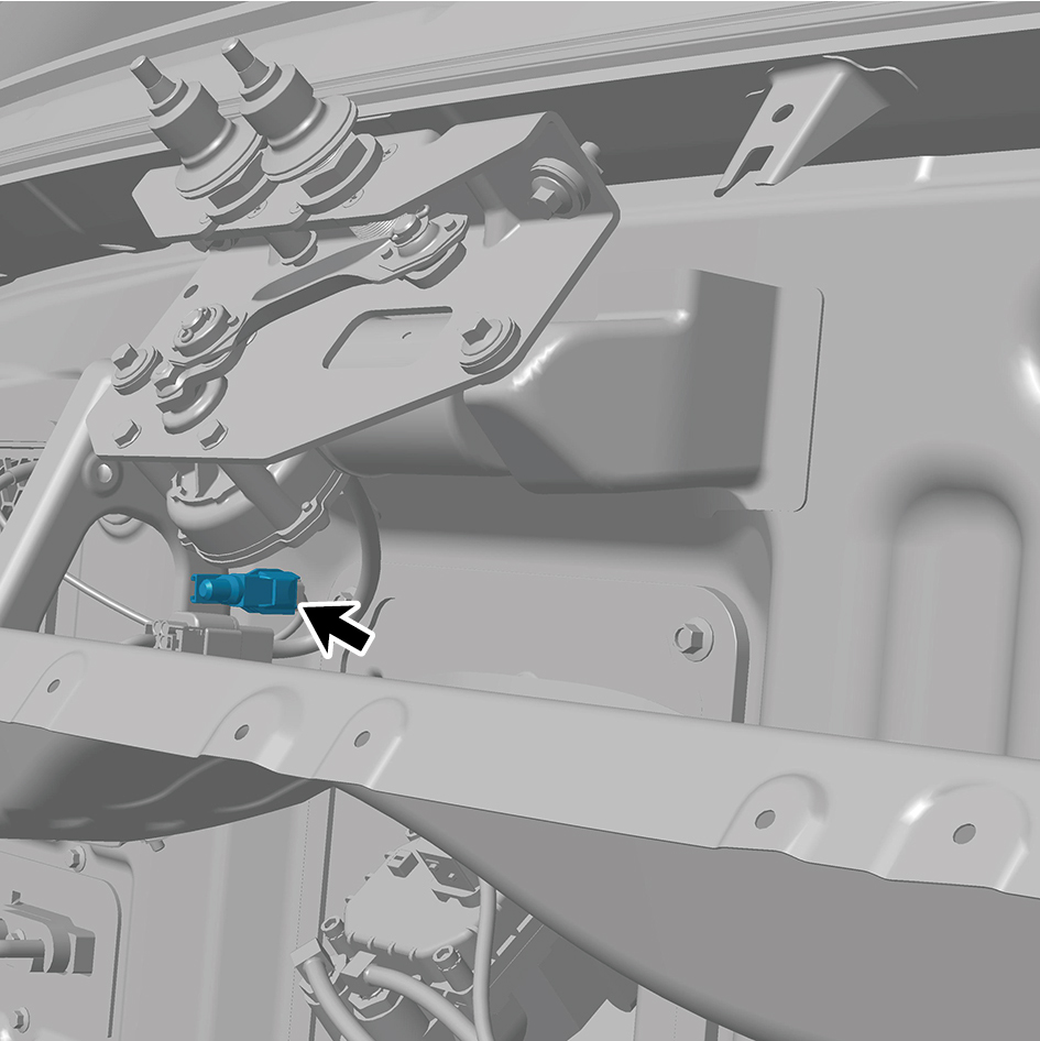
temperature sensor.
7
Disengage 1 fixing clip of the exterior temperature sensor.
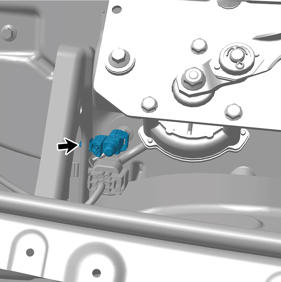
8
Remove the exterior temperature sensor.
Installation Procedures
1
Move the exterior temperature sensor to the mounting
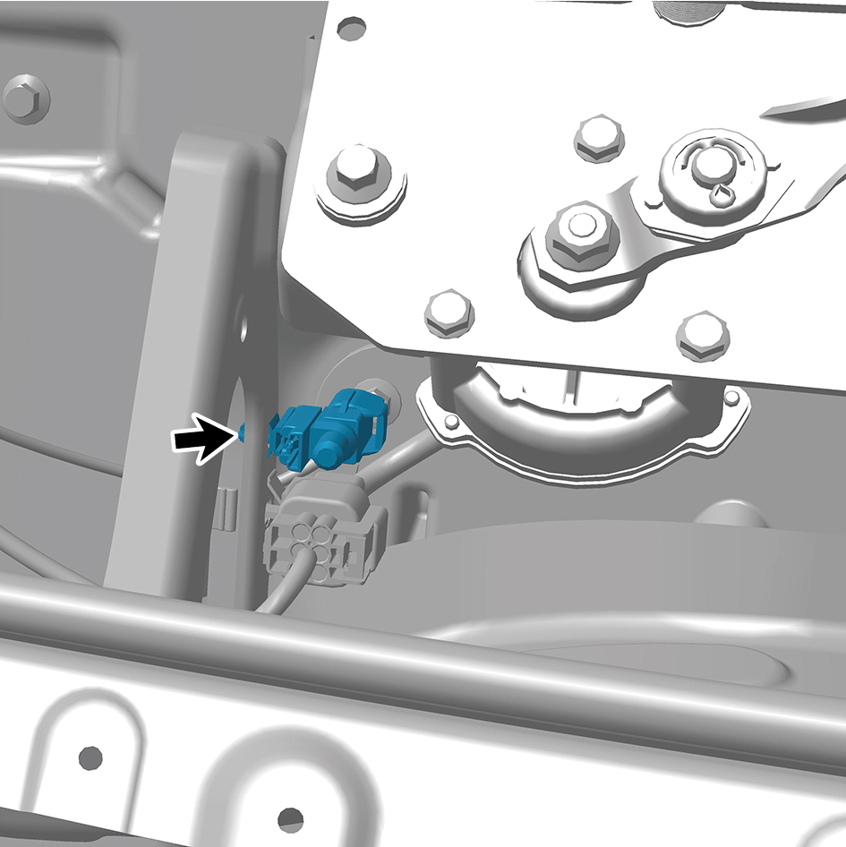
position.
2
Install 1 fixing clip of the exterior temperature sensor.
3
Connect 1 harness connector of the exterior temperature
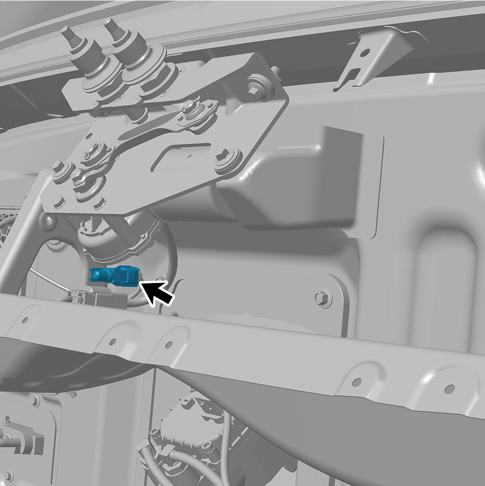
sensor.
caution
The harness is firmly connected following the
principal of "insert until a click is heard for
confirmation".
4
Install the front windshield cover plate assembly.
5
Install the primary wiper arm blade assembly (nozzle and
hose).
6
Connect the battery negative cable.
7
Close the front flip cover plate.
8
Close the door
7.1.6.6 Replacement of Interior Temperature Sensor (rear)
Sensor (rear)
Removal Procedures
1
Open the door.
2
Open the front flip cover plate.
3
Disconnect the battery negative cable.
caution
power down the high-voltage system before
disconnecting the negative pole of the storage
battery.
4
Disconnect 1 harness connector of the interior
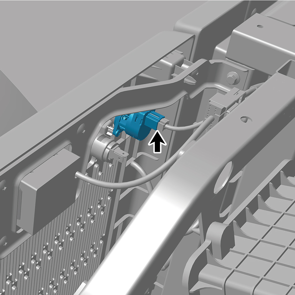
temperature sensor (rear).
5
Remove 2 fixing screws of the interior temperature sensor
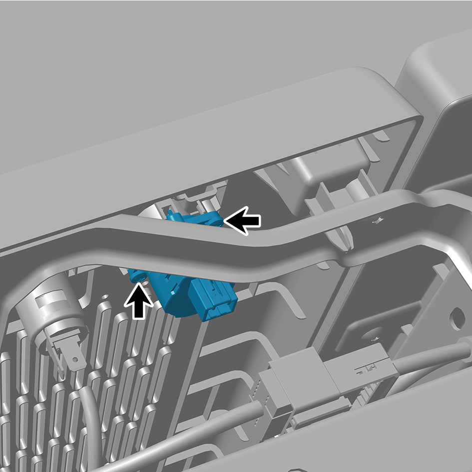
(rear).
6
Remove the interior temperature sensor (rear).
Installation Procedures
1
Move the interior temperature sensor (rear) to the
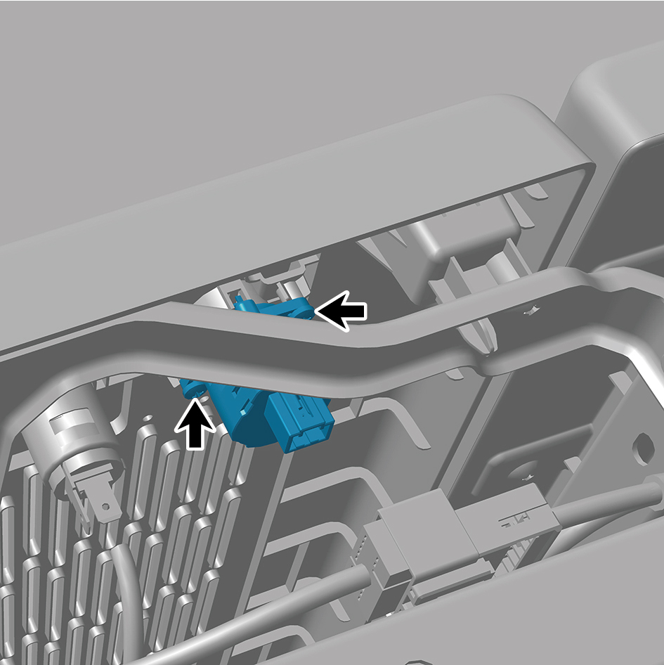
mounting position.
2
Install 2 fixing screws of the interior temperature sensor
(rear).
3
Connect 1 harness connector of the interior temperature
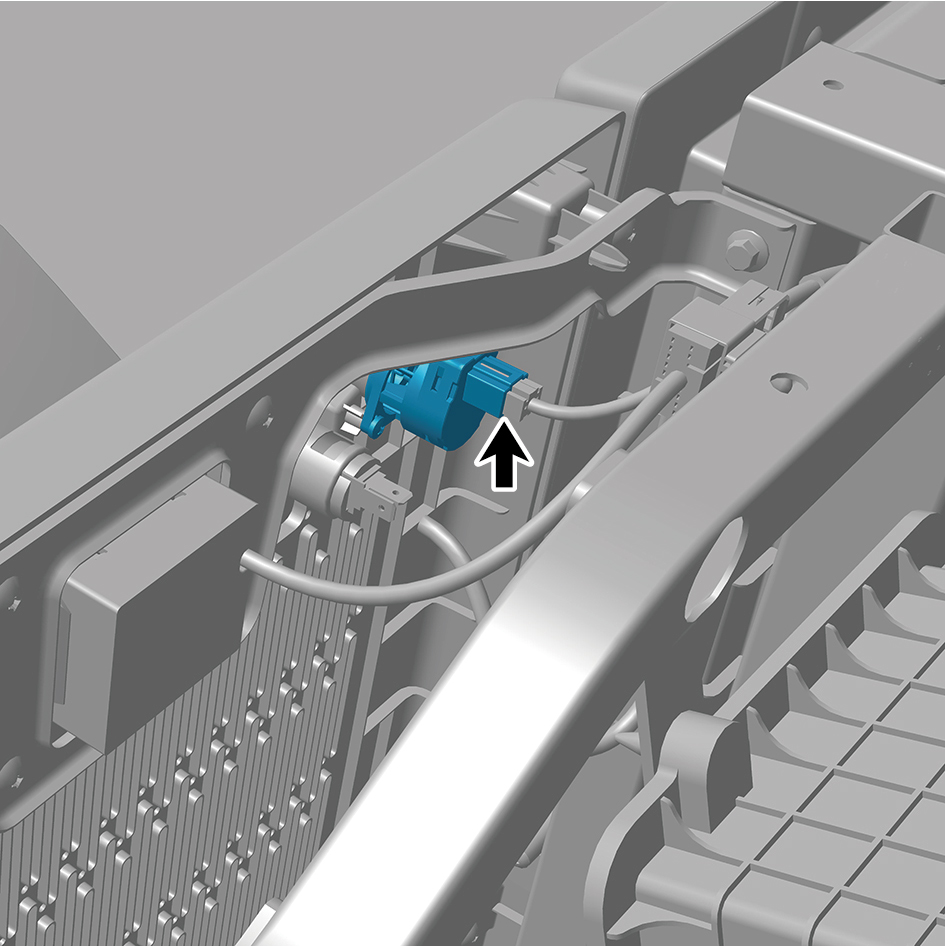
sensor (rear).
caution
The harness is firmly connected following the
principal of "insert until a click is heard for
confirmation".
4
Connect the battery negative cable.
5
Close the front flip cover plate.
6
Close the door.
7.1.6.7 Replacement of Front A/C Filter Element
Element
Removal Procedures
1
Open the door.
2
Open the front flip cover plate.
3
Remove the primary wiper arm blade assembly (nozzle
and hose).
4
Remove the front windshield cover plate assembly.
5
Press 2 clips of the cover plate.
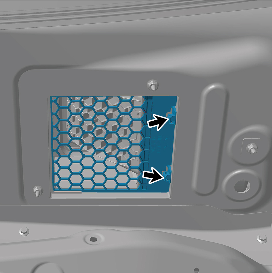
6
Remove the cover plate.
7
Pull out the front A/C filter element.
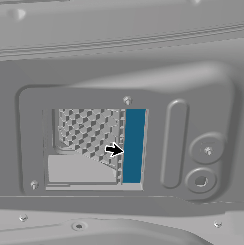
Installation Procedures
1
Install the front A/C filter element.
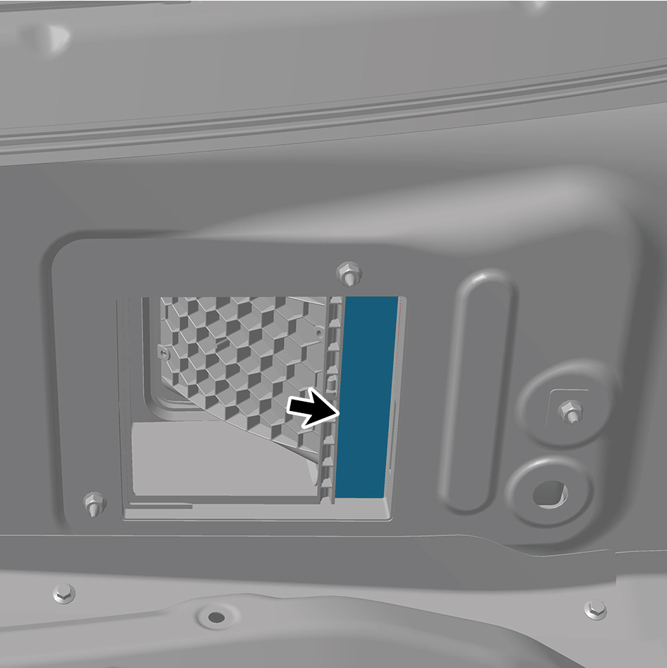
2
Install the cover plate.
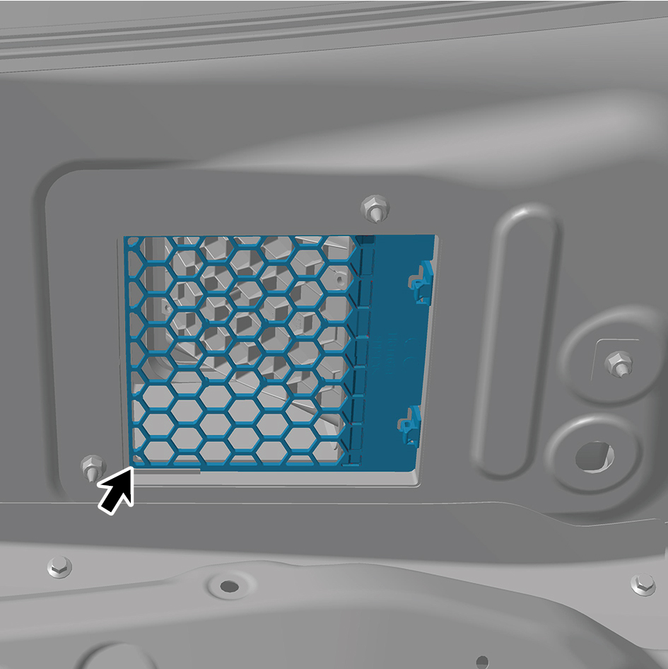
3
Install the front windshield cover plate assembly.
4
Install the primary wiper arm blade assembly (nozzle and
hose).
5
Close the front flip cover plate.
6
Close the door.
7.1.6.8 Replacement of Rear A/C Filter Element
Element
Removal Procedures
1
Open the door.
2
Lift up the sleeper mat assembly.
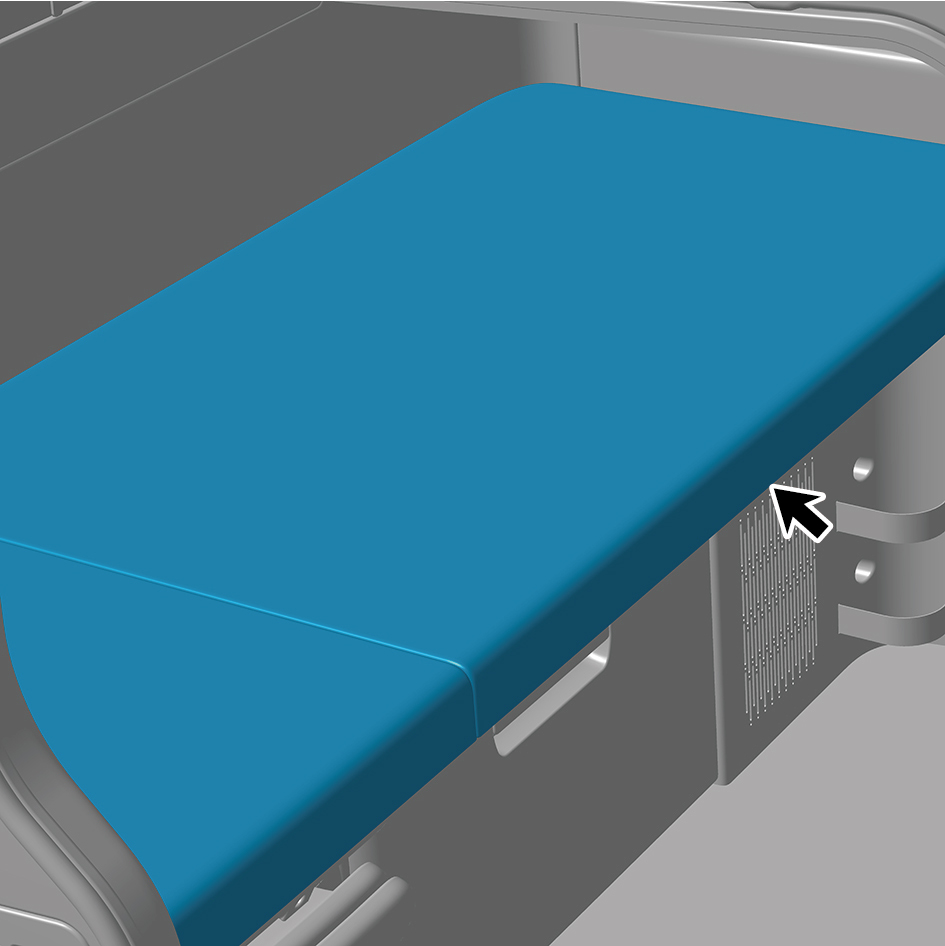
3
Press 2 clips of the cover plate.
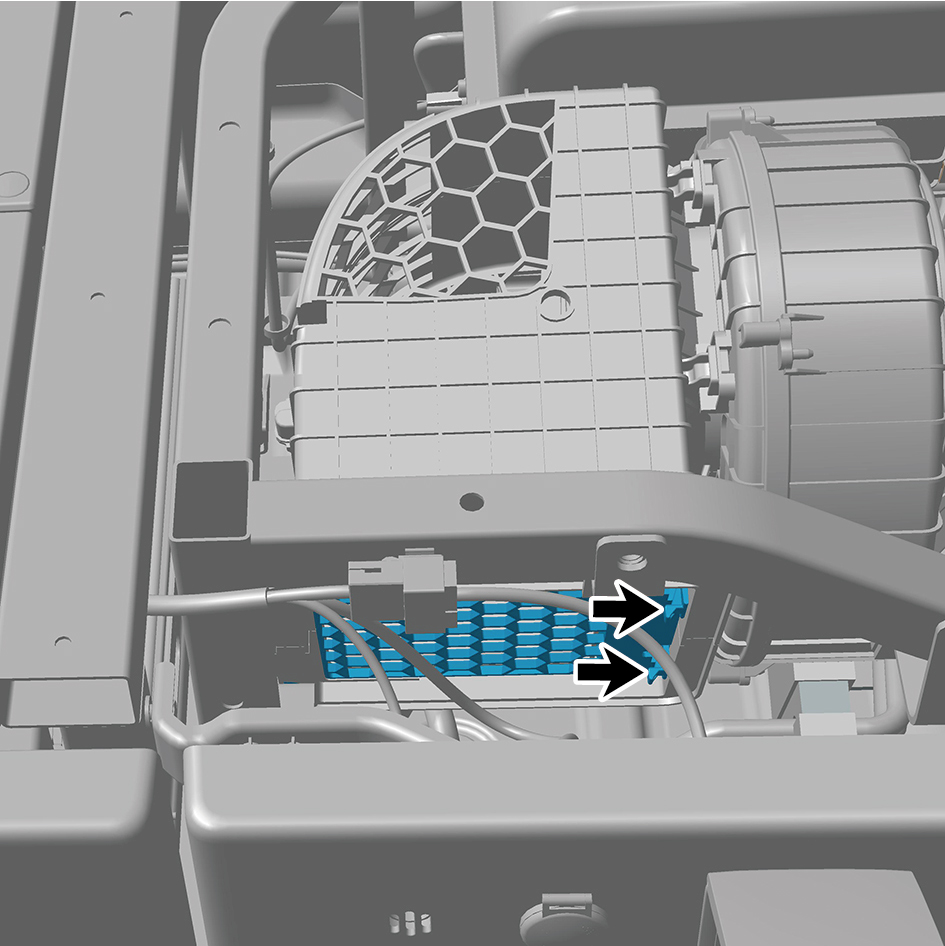
4
Remove the cover plate.
5
Pull out the rear A/C filter element.
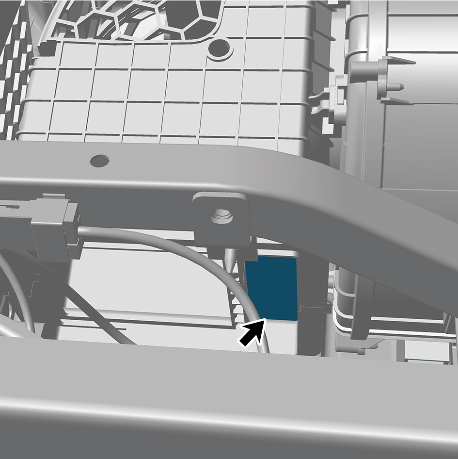
Installation Procedures
1
Install the rear A/C filter element.
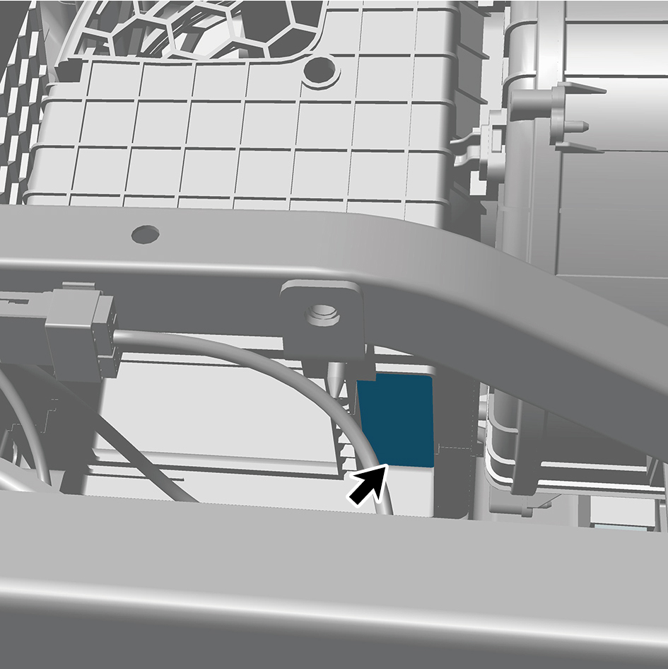
2
Install the cover plate.
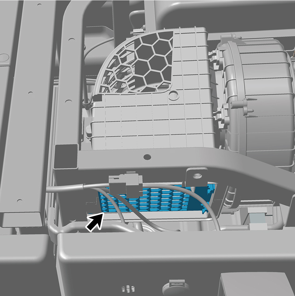
3
Install the sleeper mat assembly.
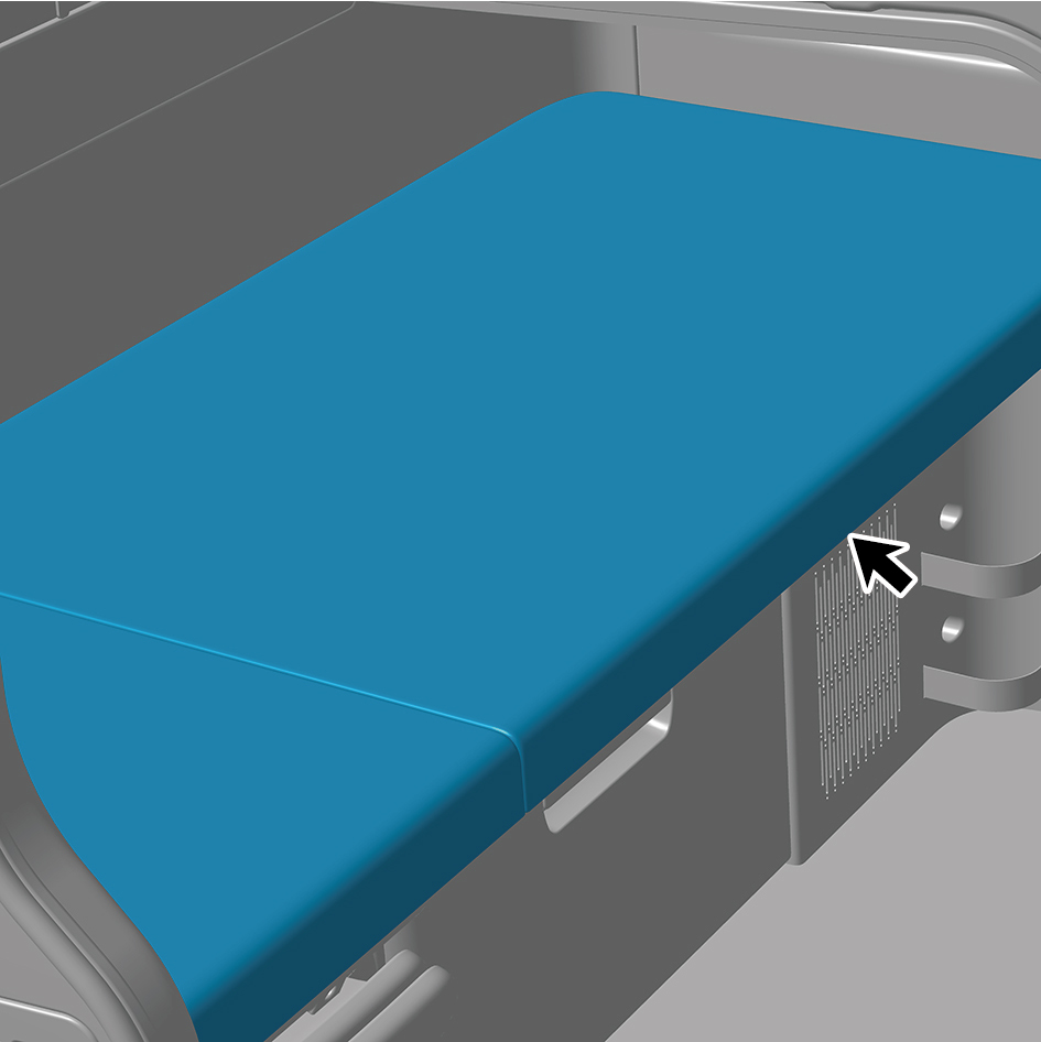
4
Close the door.