← Back to Contents
6 Vehicle Body / 6.44 Boarding Step Device | PDF pages 1039-1048
6.44 Boarding Step Device
6.44 Boarding Step Device
6.44.1 Specifications
6.44.1.1 Fastener Specifications
Range Of Torque
Fastener Specifications
Specifications
Foot Pounds of Torque (ft lbs)
The fixing bolt connecting the upper
(18.5 +/- 2) ft lbs
M8
step bracket to the white body assembly
The fixing bolt connecting the upper
step pipe beam and the white body
(33 +/- 3.5) ft lbs
M10
assembly
The fixing bolt connecting the upper
step body assembly and the right front
(6.5 +/- .75) ft lbs
M6
wheel housing rear body
The fixing bolt connecting the upper
(18.5 +/- 2) ft lbs
M8
step body assembly and the wheel
cover connection bracket
6.44.2 Decomposition Diagram
6.44.2.1 Decomposition Diagram
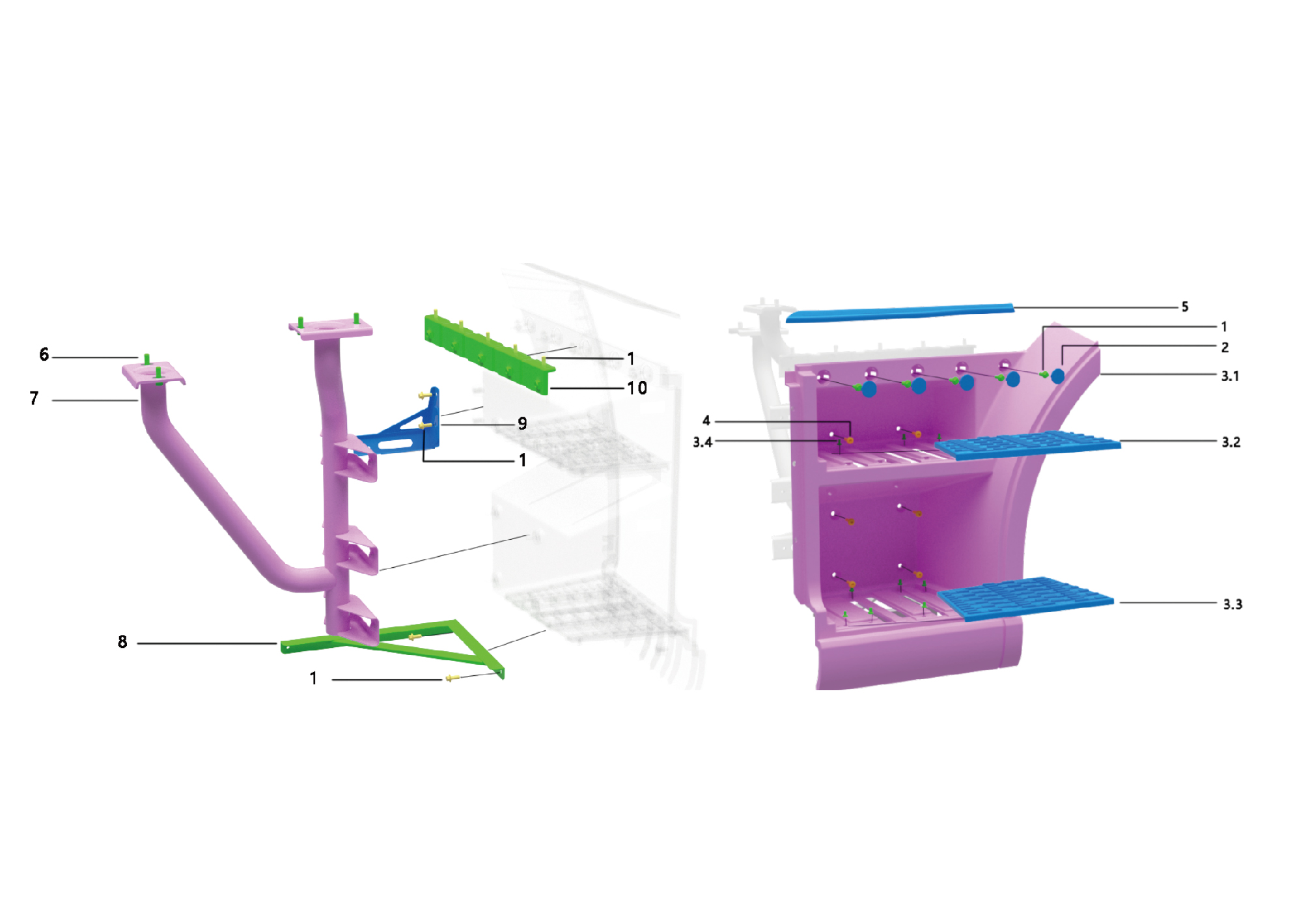
5.
1.
Hexagon Flange Bolt
Outer Decorative Cover Plate of the Sill
2.
6.
Hexagon Flange Bolt
Plug-Stepping
7.
3.1.
Pipe Beams
Boarding Step Body
3.2.
8.
Attachment Brkt-Lower Wheel Arch
Secondary Step Mat
3.3.
9.
Attachment Brkt-Upper Wheel Arch
Primary Step Mat
3.4.
10.
Pedal Bracket
Cross Recessed Pan Head Machine Screw
4.
Hex Socket Set Screw
6.44.3 Dismantling and Installation
6.44.3.1 Replacement of Boarding Step Body Assembly
Assembly
Removal Procedures
1
Open the door.
2
Open the front flip cover plate.
3
Disconnect the battery negative cable.
caution
power down the high-voltage system before
disconnecting the negative pole of the storage
battery.
4
Remove the plug cap.
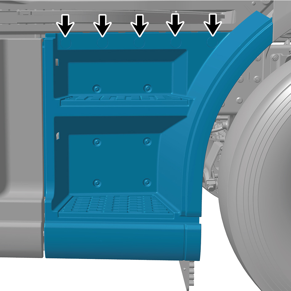
5
Remove the 3 fixing bolts of the main body assembly of
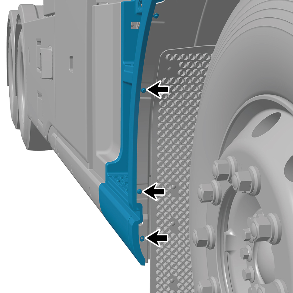
the get on the bus and step on the main assy.
6
Disengage 1 snap fastener of the main body assembly of
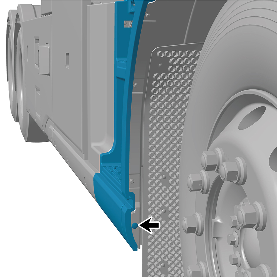
the get on the bus and step on the main assy.
7
Remove the 6 fixing screws of the main body assembly of
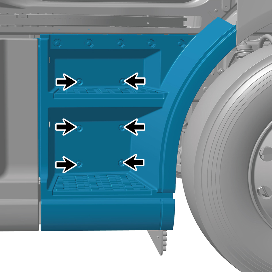
the get on the bus and step on the main assy.
8
Remove the 4 fixing screws of the main body assembly of
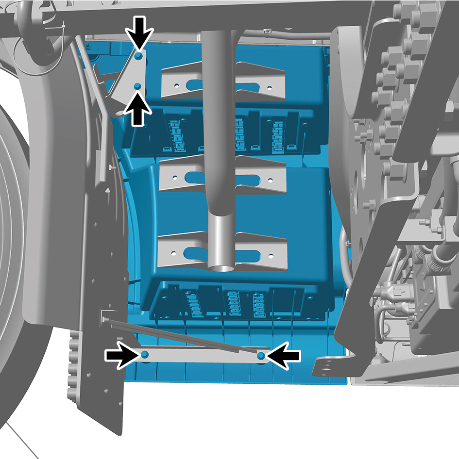
the get on the bus and step on the main assy.
9
Remove the 5 fixing bolts of the main body assembly of
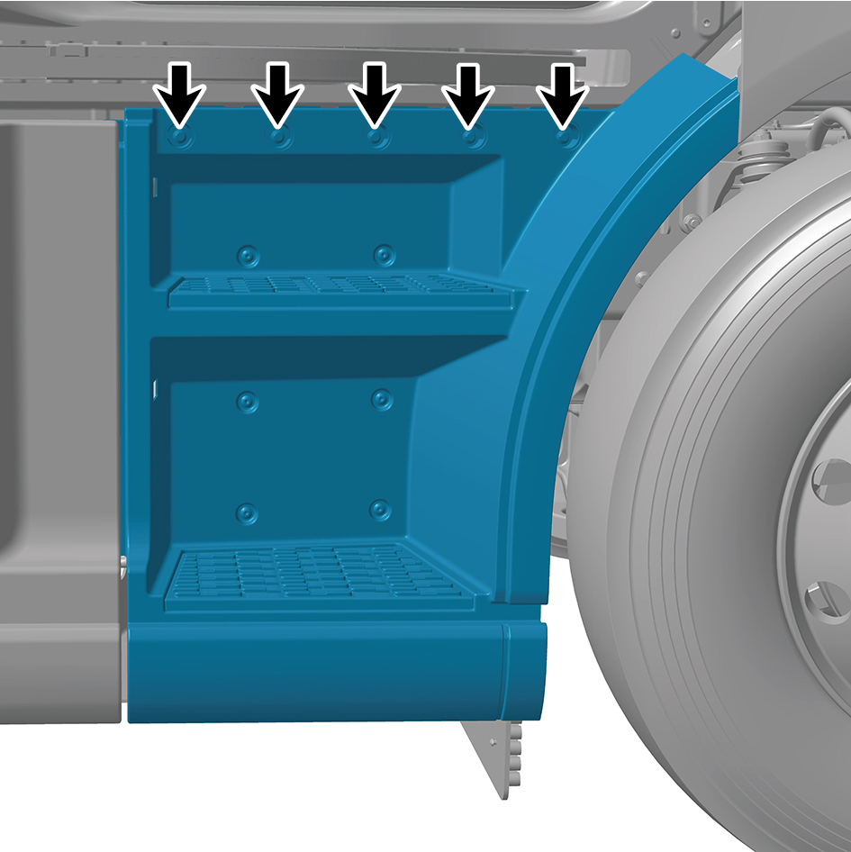
the get on the bus and step on the main assy.
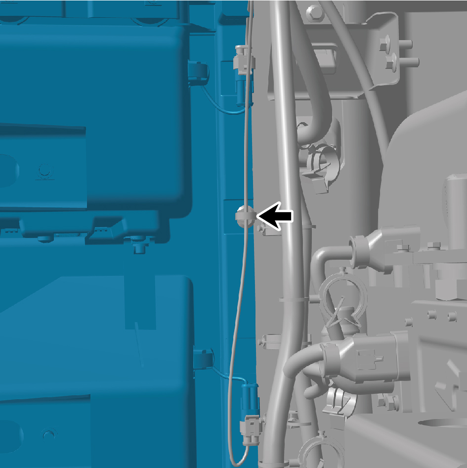
10
Separate 1 snap fastener.
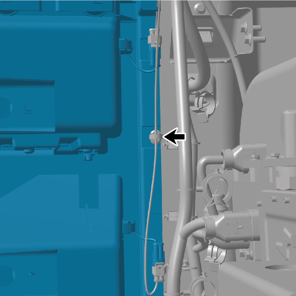
11
Disconnect 2 wire harness connectors.
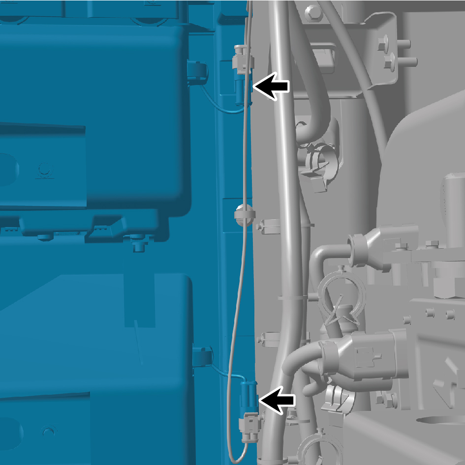
12
Take off the main body assembly of the get on the bus and
step on the main assy.
Installation Procedures
1
Install the main body assembly of the get on the bus and
step on the main assy.
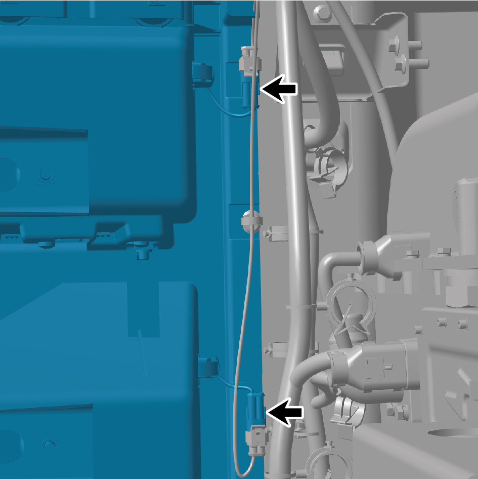
2
Connect 2 wire harness connectors.
3
Connect 1 snap fastener.
4
Install the 5 fixing bolts of the main body assembly of the
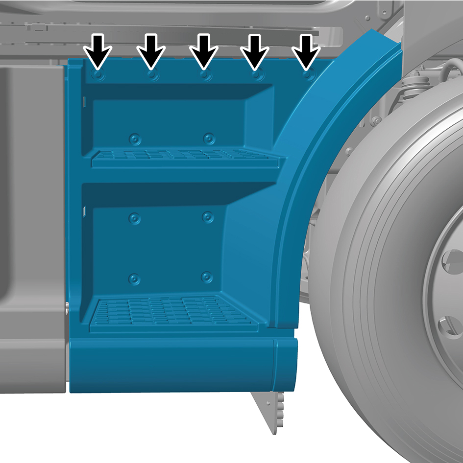
get on the bus and step on the main assy.
Torque:(18.5 +/- 2) ft lbs
5
Install the 4 fixing bolts of the main body assembly of the
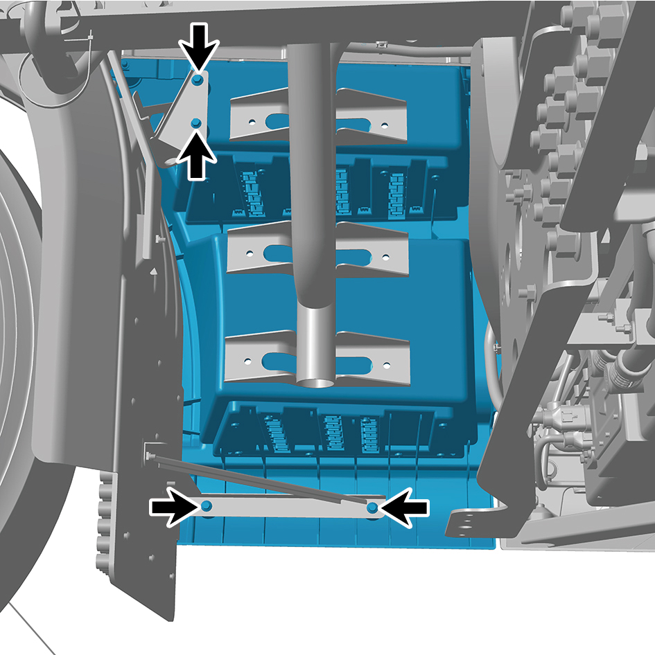
get on the bus and step on the main assy.
Torque: (18.5 +/- 2) ft lbs
6
Install the 6 fixing screws of the main body assembly of
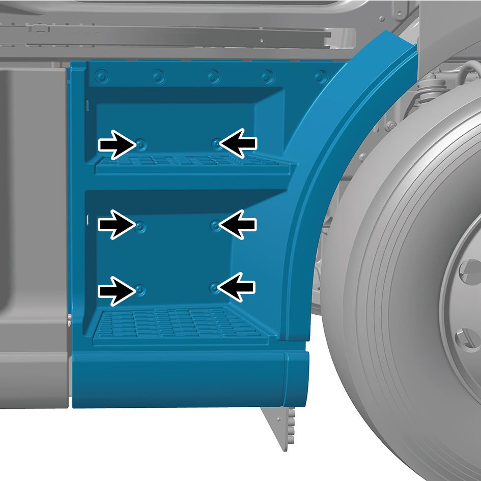
the get on the bus and step on the main assy.
7
Install 1 snap fastener of the main body assembly of the
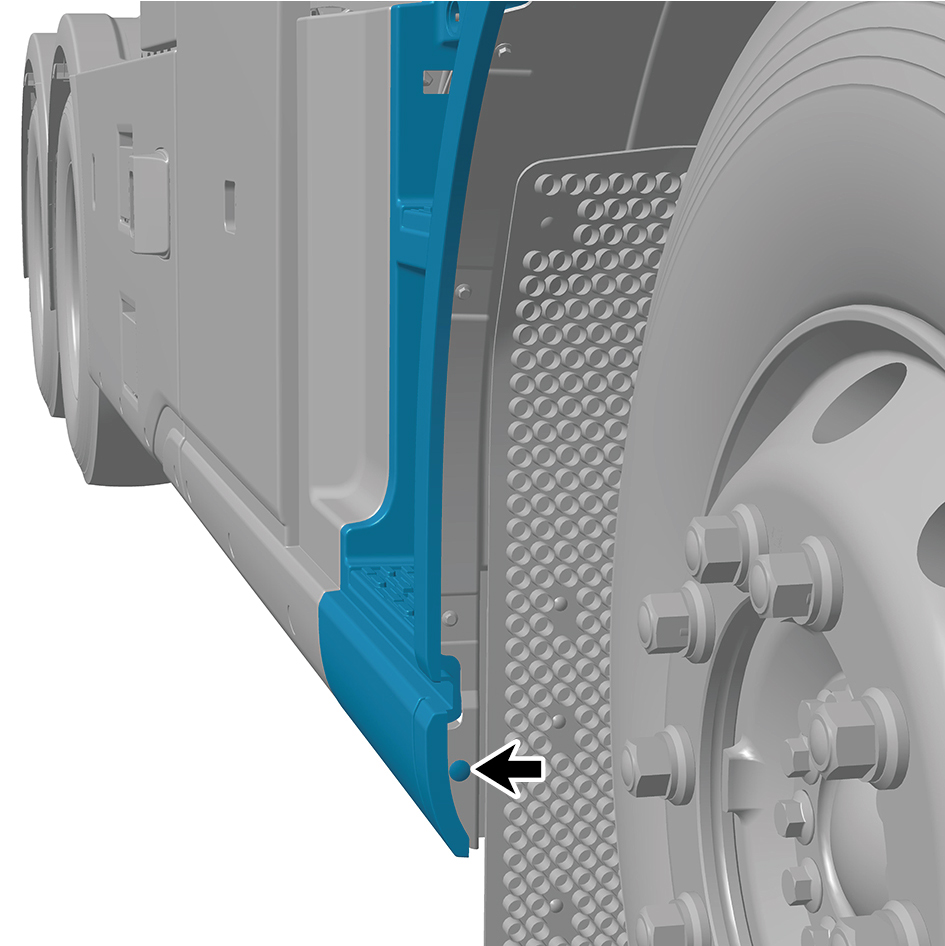
get on the bus and step on the main assy.
8
Install the 3 fixing bolts of the main body assembly of the
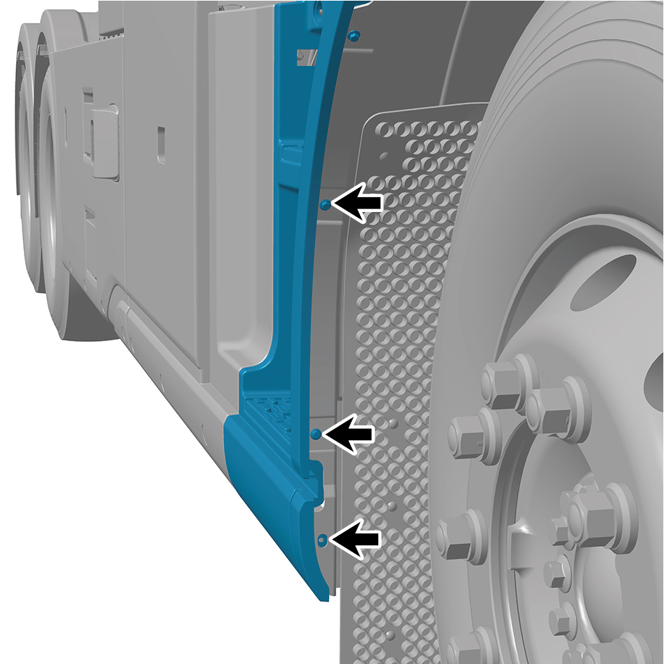
get on the bus and step on the main assy.
Torque:(6.5 +/- .75) ft lbs
9
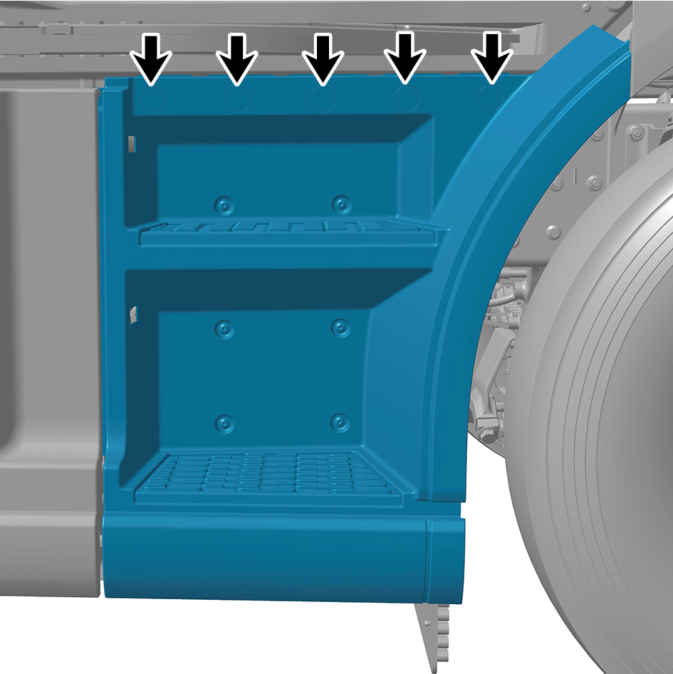
Install the plug cap.
10
Connect the battery negative cable.
11
Close the front flip cover plate.
12
Close the door.