← Back to Contents
6 Vehicle Body / 6.33 Door Hinge Device | PDF pages 940-949
6.33 Door Hinge Device
6.33 Door Hinge Device
6.33.1 Specifications
6.33.1.1 Fastener Specifications
Range Of Torque
Fastener Specifications
Specifications
Foot Pounds of Torque (ft lbs)
The fixing bolts between the upper
hinge assembly and the sliding door
(18.5 +/- 2) ft lbs
M8
inner panel assembly
The fixing bolt connecting the middle
hinge assembly and the sliding door
(18.5 +/- 2) ft lbs
M8
inner panel assembly
The fixing bolt connecting the lower
chain assembly and the sliding door
(18.5 +/- 2) ft lbs
M8
inner panel assembly
The fixing nut connecting the lower
hinge assembly and the ground lock
(6.5 +/- .75) ft lbs
M6
assembly
6.33.2 Decomposition Diagram
6.33.2.1 Decomposition Diagram
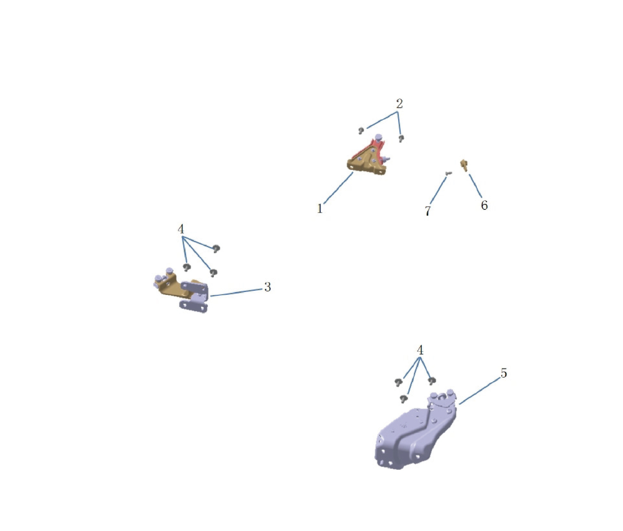
5.
1.
Hinge Assy Upr
Hinge Assy Lwr
2.
Hexagon Flange Bolt
6.
Upper Hinge Guide Pin Holder
7.
3.
Hinge Assy Mid
Hex Socket Set Screw
4.
Hexagon Head Bolt Assy
6.33.3 Dismantling and Installation
6.33.3.1 Replacement of Upper Hinge Assembly
Assembly
Removal Procedures
1
Open the door.
2
Remove 2 fixing bolts connecting the upper hinge
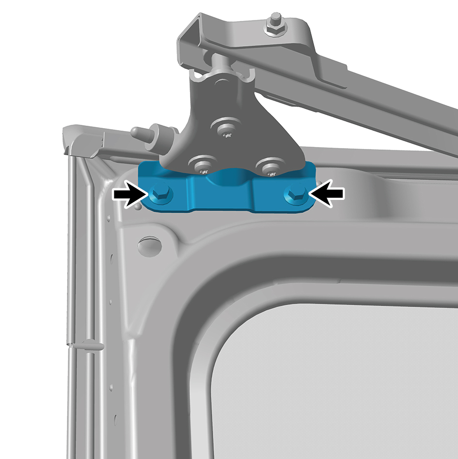
assembly to the sliding door assembly.
3
Remove 3 fixing screws of the upper hinge assembly.
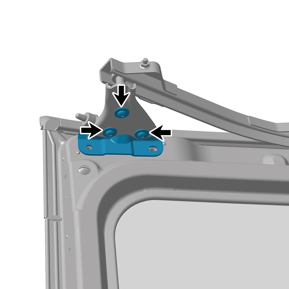
4
Remove the upper hinge assembly.
Installation Procedures
1
Move the upper hinge assembly to the mounting position.
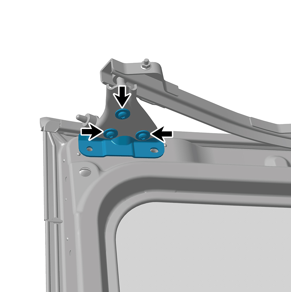
2
Install 3 fixing screws of the upper hinge assembly.
3
Install 2 fixing bolts connecting the upper hinge assembly
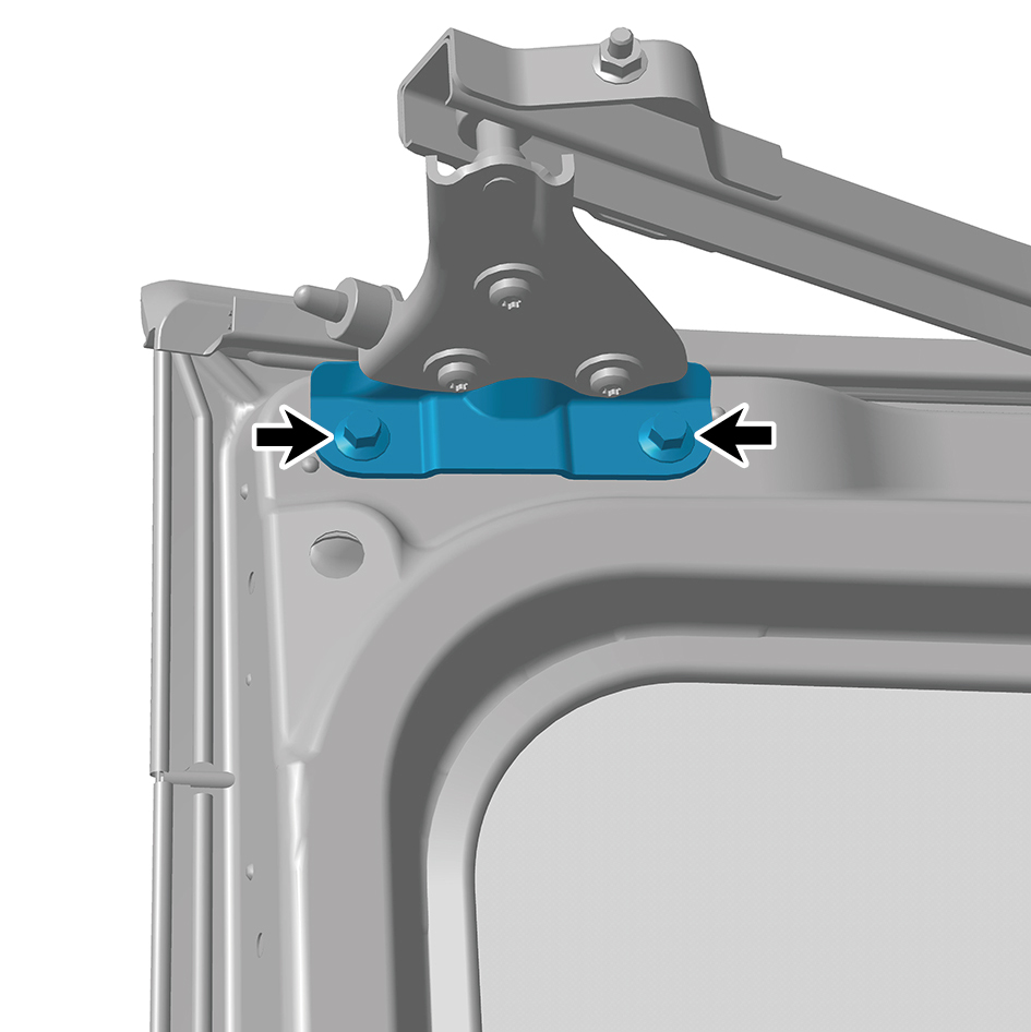
to the sliding door assembly.
Torque:(18.5 +/- 2) ft lbs
4
Close the door.
6.33.3.2 Replacement of Middle Hinge Assembly
Assembly
Removal Procedures
1
Open the door.
2
Remove the right side wall slide rail cover plate assembly.
3
Remove the right side wall slide rail end cover plate
assembly.
4
Separate the mingle hinge assembly from the sliding door
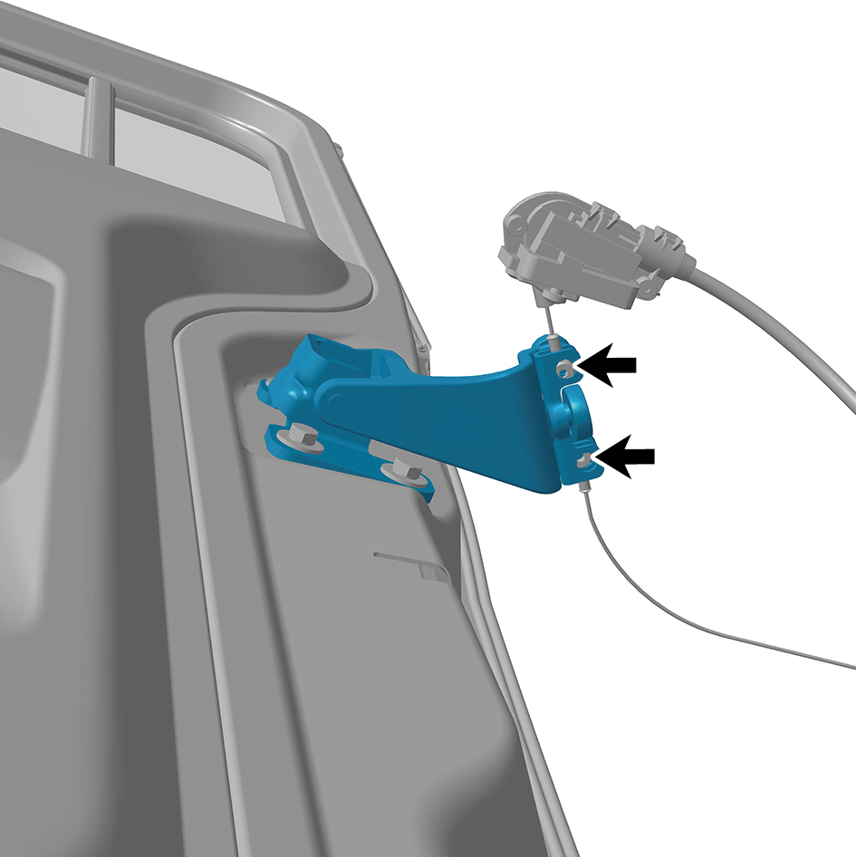
driver assembly.
5
Remove 1 fixing nut connecting the middle hinge
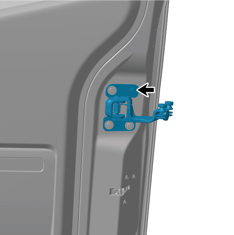
assembly to the sliding door assembly.
6
Remove 3 fixing bolts connecting the middle hinge
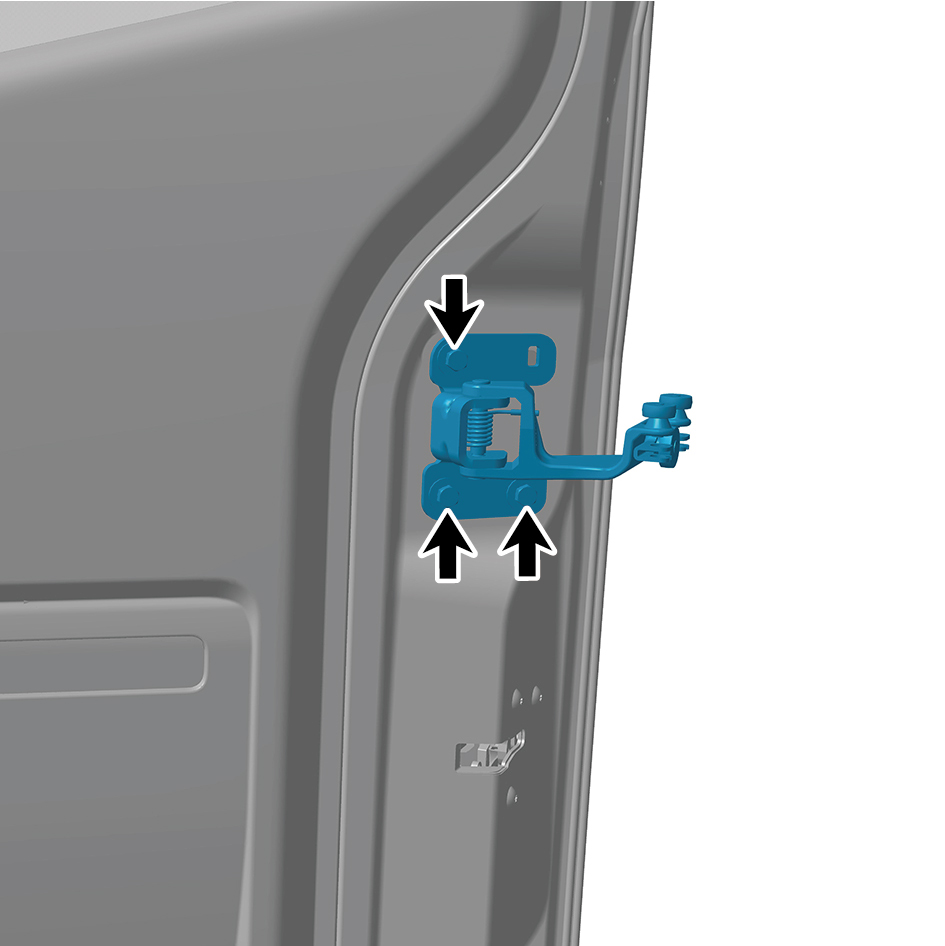
assembly to the sliding door assembly.
7
Remove the middle hinge assembly.
Installation Procedures
1
Move the middle hinge assembly to the mounting position.
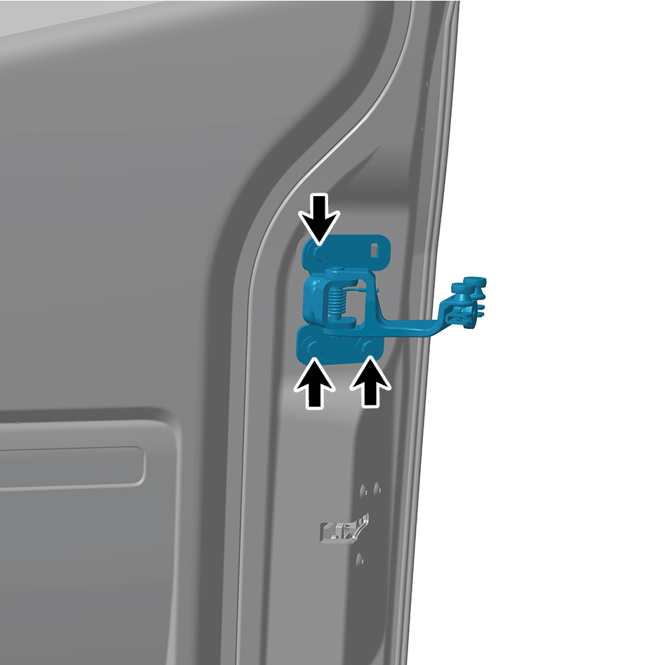
2
Install 3 fixing bolts connecting the middle hinge assembly
to the sliding door assembly.
Torque:(18.5 +/- 2) ft lbs
3
Install 1 fixing nut connecting the middle hinge assembly
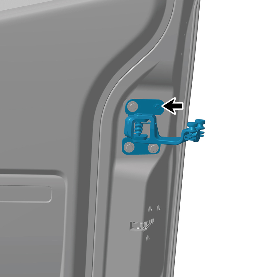
to the sliding door assembly.
Torque: (18.5 +/- 2) ft lbs
4
Connect the mingle hinge assembly to the sliding door
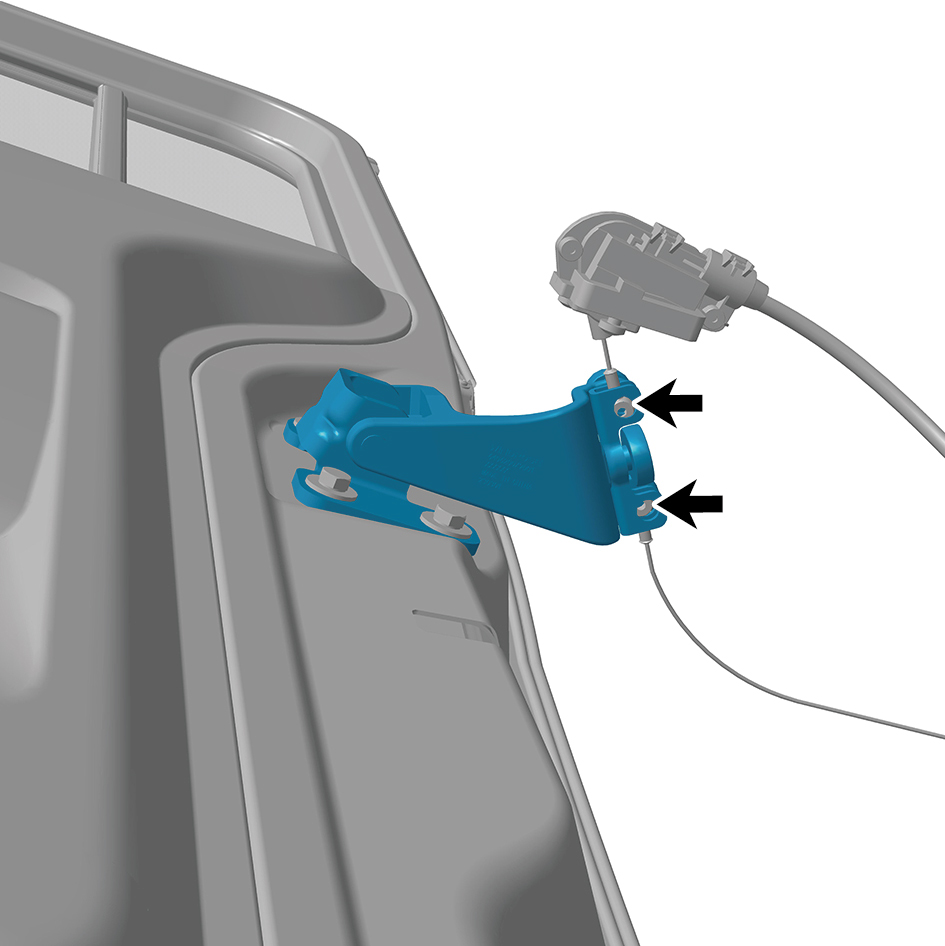
driver assembly.
5
Install the right side wall slide rail end cover plate
assembly.
6
Install the right side wall slide rail cover plate assembly.
7
Close the door.
6.33.3.3 Replacement of Lower Hinge Assembly
Assembly
Removal Procedures
1
Open the door.
2
Remove 2 fixing nuts connecting the lower hinge
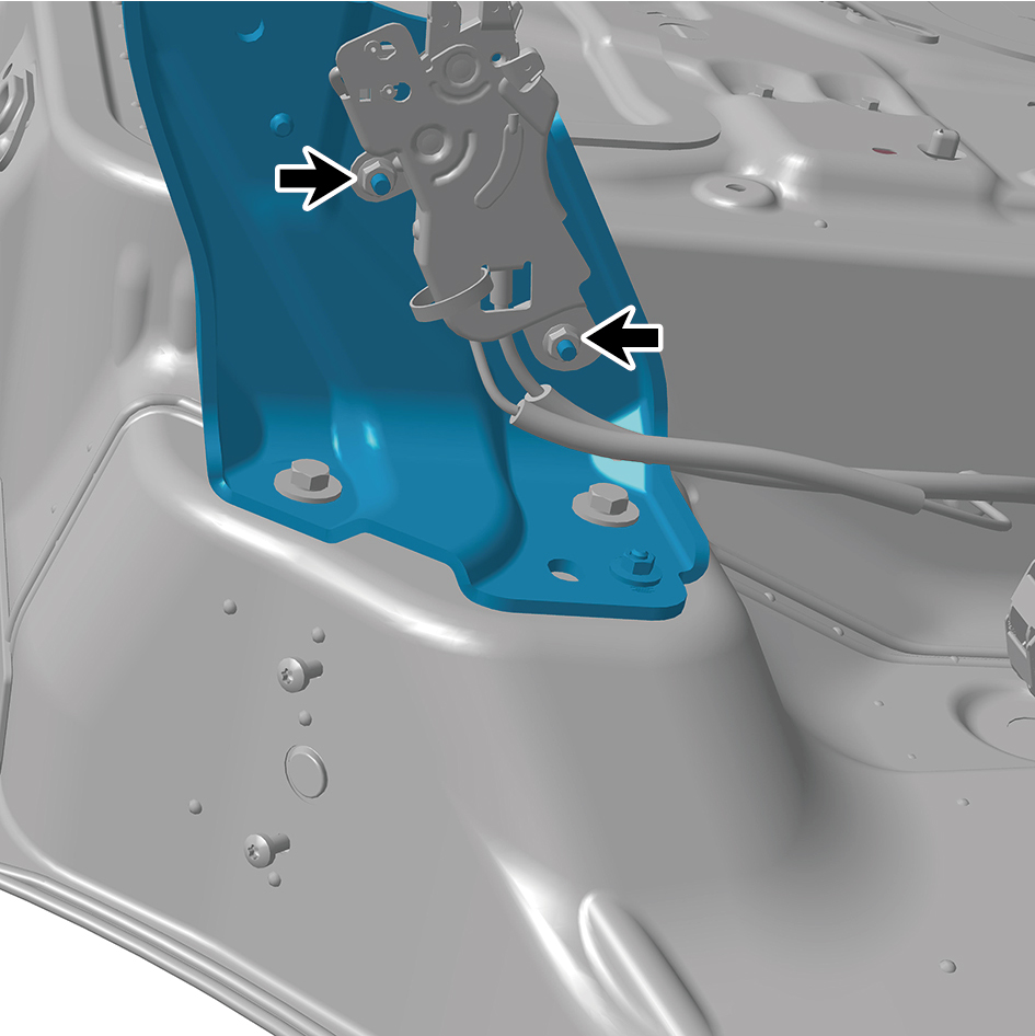
assembly to the ground lock assembly.
3
Remove 1 fixing nut connecting the lower hinge assembly
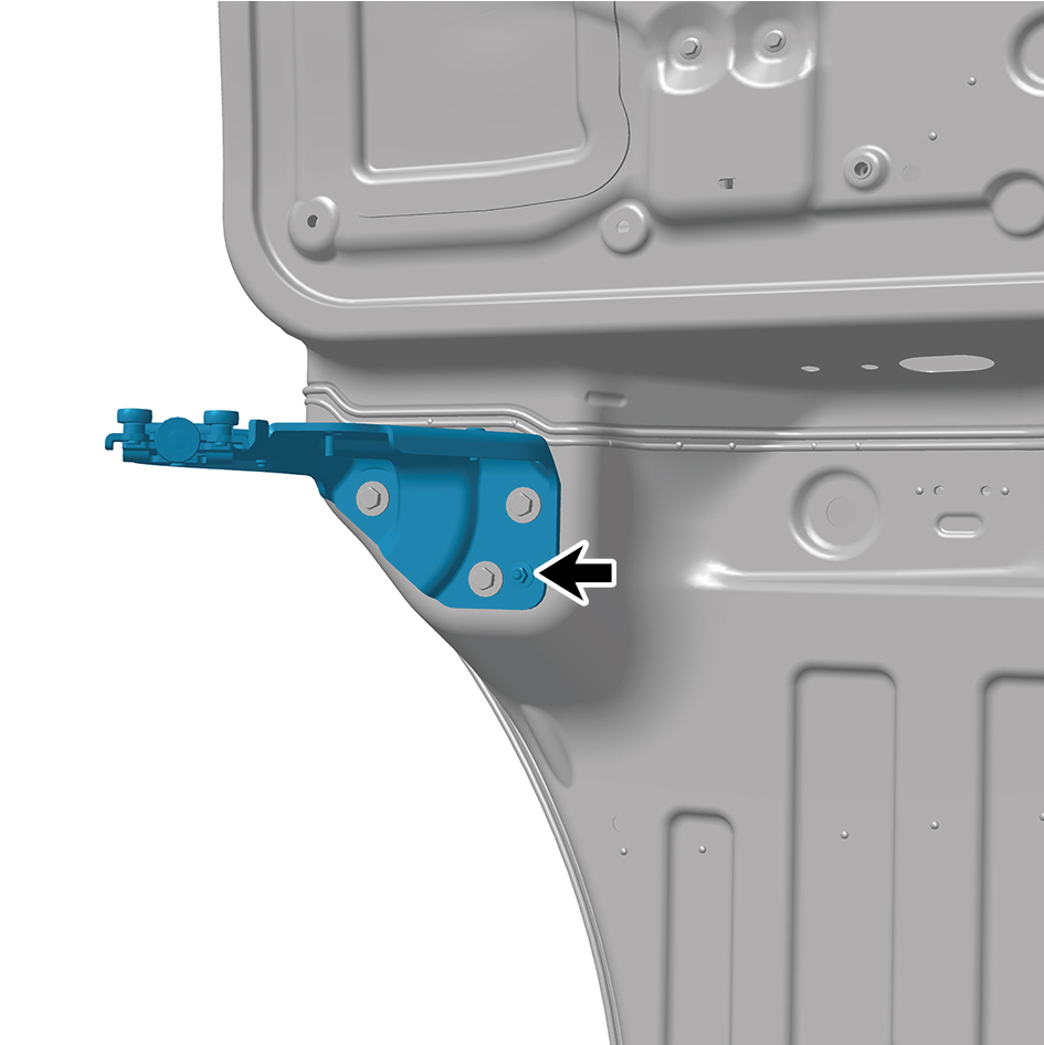
to the sliding door assembly.
4
Remove 3 fixing bolts connecting the lower hinge
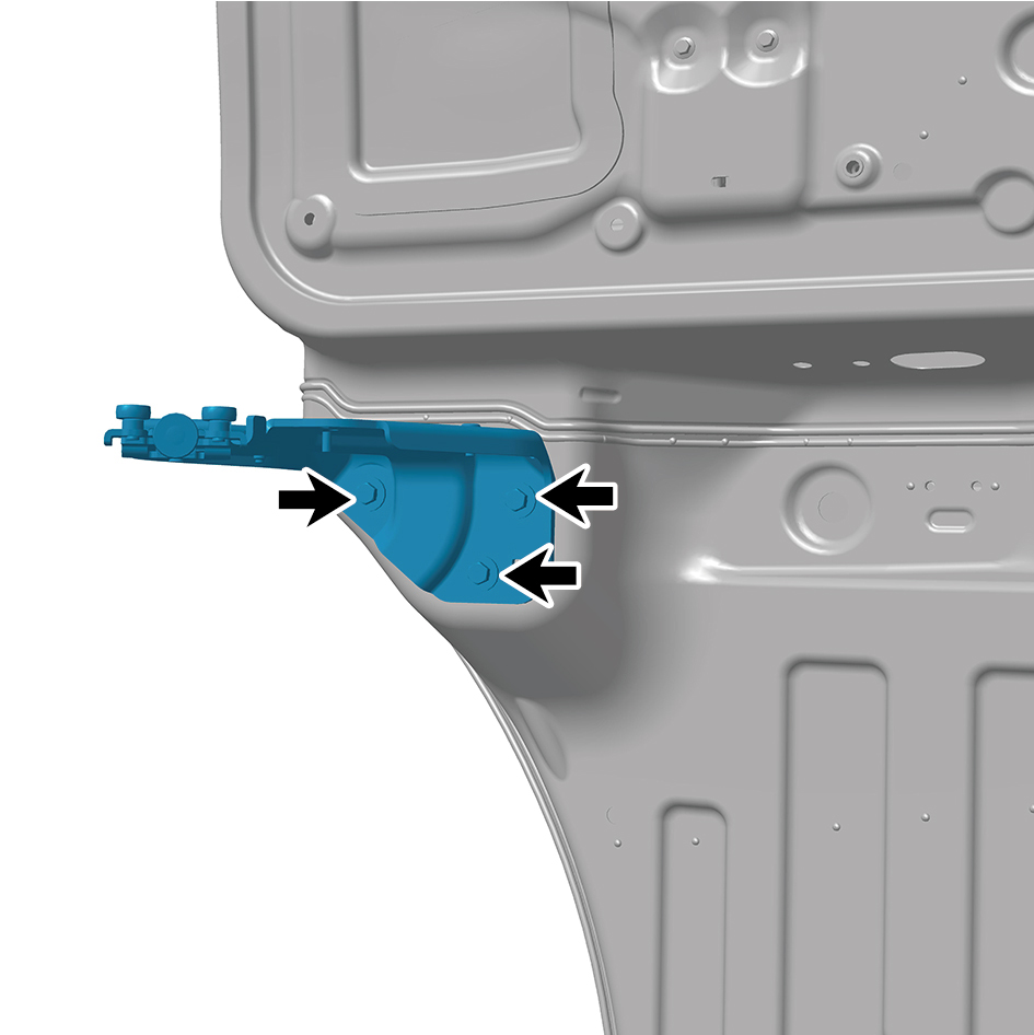
assembly to the sliding door assembly.
5
Remove 2 fixing screws of the lower hinge assembly.
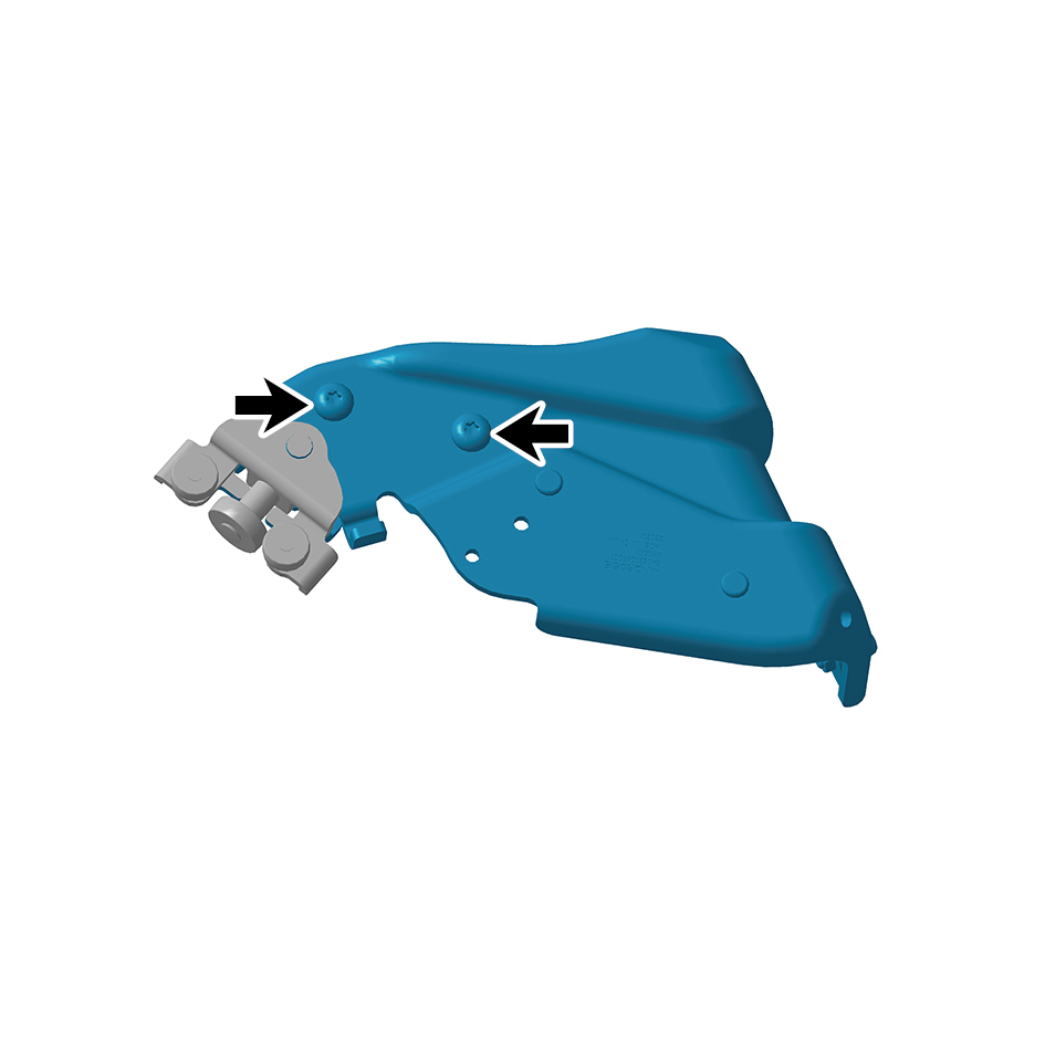
6
Remove the lower hinge assembly.
Installation Procedures
1
Move the lower hinge assembly to the mounting position.
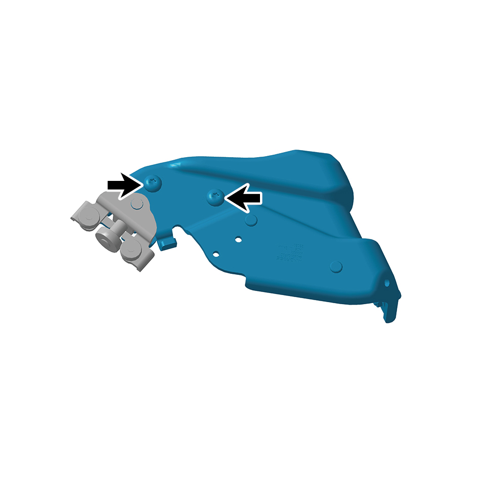
2
Install 2 fixing screws of the lower hinge assembly.
3
Install 3 fixing bolts connecting the lower hinge assembly
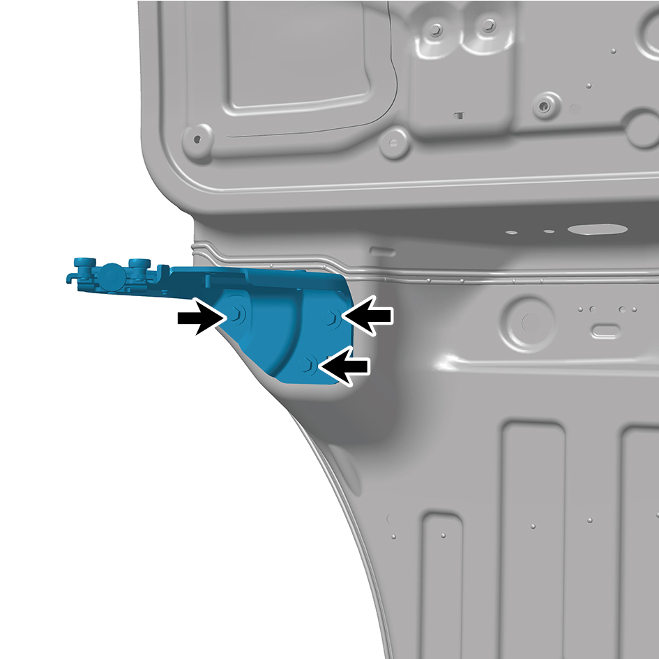
to the sliding door assembly.
Torque: (18.5 +/- 2) ft lbs
4
Install 1 fixing nut connecting the lower hinge assembly to
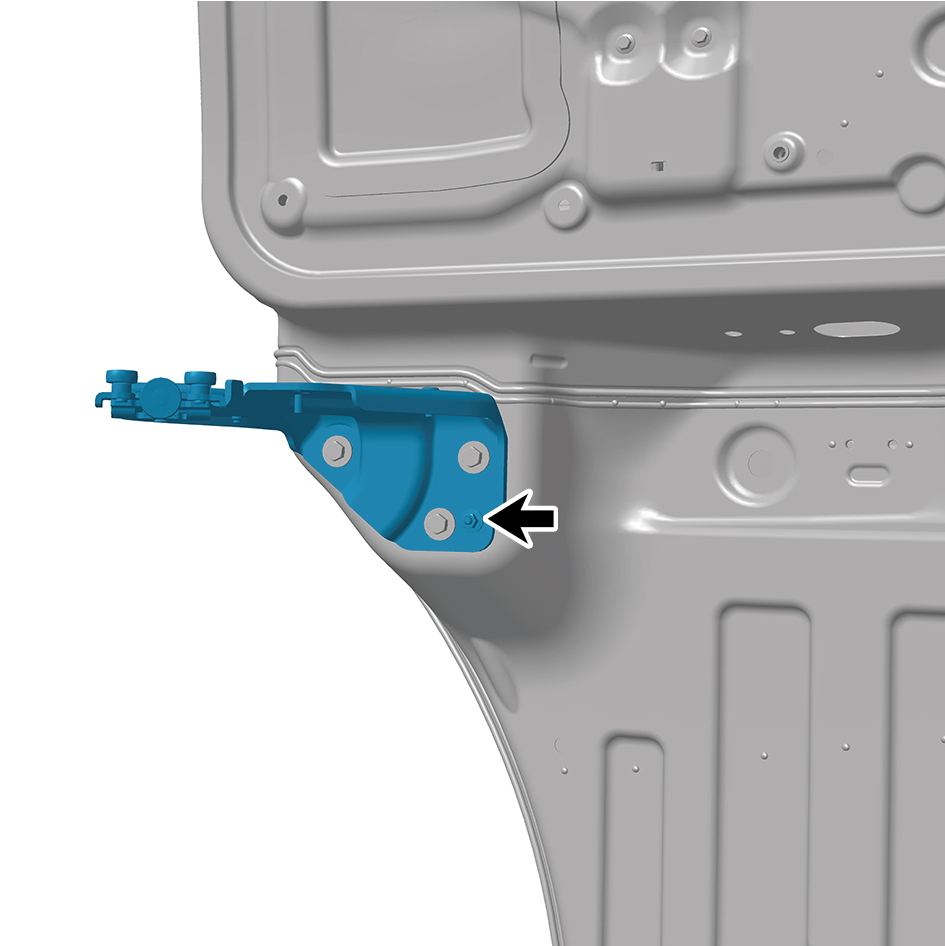
the sliding door assembly.
Torque: (18.5 +/- 2) ft lbs
5
Install 2 fixing nuts connecting the lower hinge assembly
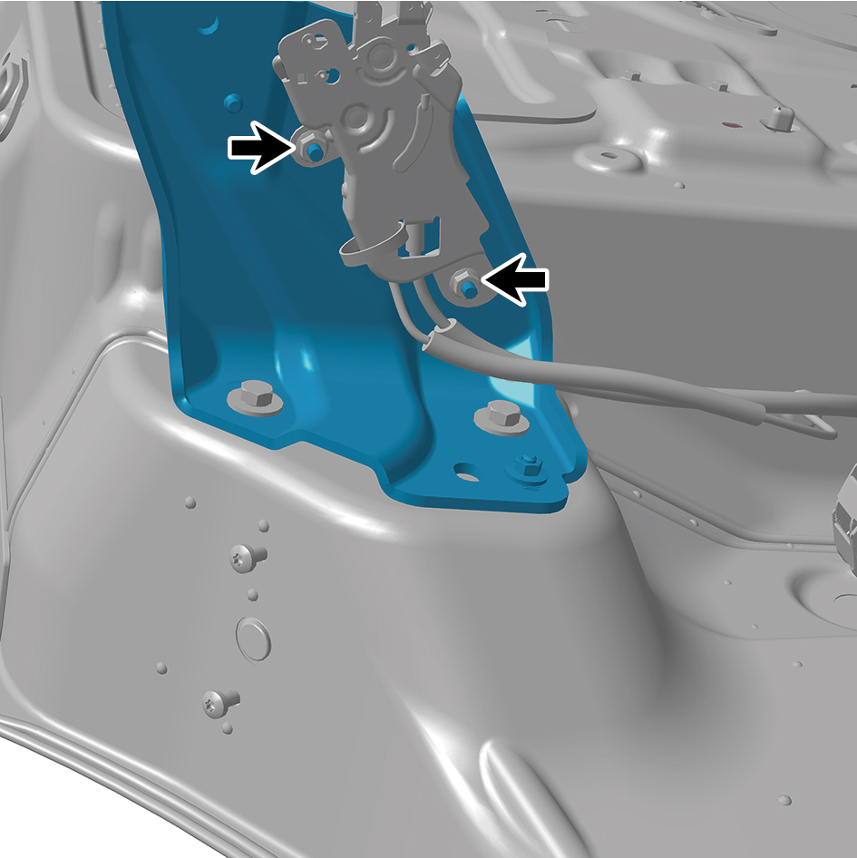
to the ground lock assembly.
Torque: (6.5 +/- .75) ft lbs
6
Close the door.