← Back to Contents
6 Vehicle Body / 6.32 Sliding Door Accessory Device | PDF pages 893-939
6.32 Sliding Door Accessory Device
6.32 Sliding Door Accessory Device
6.32.1 Specifications
6.32.1.1 Fastener Specifications
Range Of Torque
Fastener Specifications
Specifications
Foot Pounds of Torque (ft lbs)
The fixing nut connecting the ground
lock assembly and the lower hinge
(6.5 +/- .75) ft lbs
M6
assembly
The fixing bolt connecting the ground
lock buckle assembly and the side panel
(6.5 +/- .75) ft lbs
M6
outer assembly
6.32.2 Decomposition Diagram
6.32.2.1 Decomposition Diagram
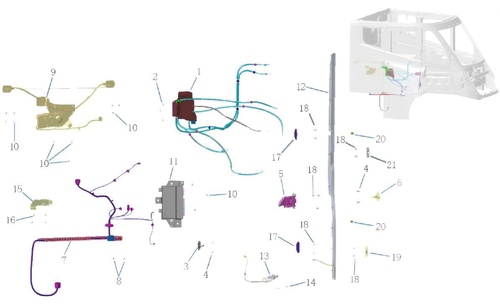
1.
Lock Assy-Rr
12.
Anti-Pinch Sensor Assr
2.
13.
Hexagon Socket Head Cap Screw
Ground Lock Assy
3.
14.
Hexagon Flange Nut
Striker -Rr
4.
15.
Hex Socket Set Screw
Striker Ground Lock Assy
5.
16.
Lock Assy-Fr
Hexagon Flange Bolt
6.
17.
Striker -Fr
Door End Guide Pin
7.
18.
Drag Chain Assy
Hexagon Socket Head Cap Screw(m6*16)
8.
19.
Hex Socket Set Screw
Guide Pin at Side Circumference End
9.
20.
Door Bumper-Rh
Slide Door Drive Unit Assy
10.
21.
Hex Socket Set Screw
Side Wall Upper Guide Pin
11.
DCM Module Assembly
6.32.3 System Schematic Diagram
6.32.3.1 Electrical Schematic Diagram
6.32.4 Diagnostic Information and Steps
6.32.4.1 Diagnosis Description
Understanding and familiarizing oneself with the working principle of the white body device before diagnosing faults in the white
body device, and then starting system diagnosis, can help determine the correct fault diagnosis steps when a fault occurs, and
more importantly, it can help determine the situation described by the customer belongs to normal operation. Any fault diagnosis
of the white body device should start with routine inspection, guiding maintenance personnel to take the next logical step for fault
diagnosis. Understanding and correctly using the diagnostic process can shorten the diagnosis time and avoid misjudgment of
faulty parts.
6.32.4.2 Routine Inspection
• Check for aftermarket devices that may affect the operation of the body in white system, ensuring that these devices do not
affect the operation of the body in white system.
• Inspect system components that are easily accessible or visible to make sure they are not visibly damaged or have conditions
that could cause failure.
6.32.4.3 Fault Symptom Table
Symptom
Suspected Faulty Project
Measures
1. There is electromagnetic interference
Move to an undisturbed environment for
in the usage environment
use.
2. NFC key bending, damage,
Inspect the NFC key and replace it if
NFC key cannot lock/open the car door
demagnetization
necessary.
Fault definition:NFC key cannot lock/
open the car door, the vehicle's central
3. NFC key anti-theft loss
Reprogram the NFC key.
control switch unlocks the door
Repair Bluetooth&NFC module, replace
normally.
Bluetooth if necessary&NFC module.
4. Bluetooth&NFC module fault
Refer to Replacement Of Concealed
External Handle Assembly
Adjust the mechanical mechanism of
the door lock and replace it if necessary.
1. Mechanical mechanism failure of
Refer to Replacement Of Front Lock
door lock
Assembly.Replacement Of Rear Lock
Assembly
2. Poor contact of wiring harness plug
Inspect the wiring harness and plugs.
The door lock bounces while driving
3. Poor contact of relevant grounding
Repair the grounding point fault.
Fault definition:During the driving
points
process of the vehicle, the door lock
Inspect the wiring harness of the car
unlocks/locks.
4. Wiring harness fault
door lock.
5. Fault in the contact switch of the
Replace the door lock motor assembly.
central locking motor
Repair the door control module and
replace it if necessary. Refer to
6. Gate control module fault
Replacement Of DCM
6.32.4.4 DTC Confirmation
1.Connect the diagnostic instrument to the diagnostic interface, read and record the DTC, and then clear the DTC.
2. Restart the vehicle.
3. Read the fault code of the control system again to confirm whether the system has a fault code output.
– Yes:Diagnose based on the output fault code.
– No:Perform intermittent fault checks, refer to Inspection Of Intermittent Fault
6.32.4.5 List Of Diagnostic Trouble Codes (DTCs)
DCM
Fault Description
Exclusion Method
Fault Code
High battery voltage
B111717
Refer to Gate Control Module Power
Fault
Low battery voltage
B111716
U007E88
BCANFD3 BusOff
U014087
Lost communication with BDCU
Refer to Communication Fault Of Door
U015687
Lost Communication With CDCU
Control Module
U012287
Lost Communication With VDC
U019887
Lost Communication With T-BOX
door lock motor open circuit
B1B0188
door lock motor short to ground or drive
B1B0189
fault
Refer to Door Lock Motor Fault
door lock motor short to battery or drive
B1B0190
fault
lock block state signal error or open lock
B1B0A01
actuator stuck
cinch motor short open circuit
B1B0288
cinch motor short to ground or drive
B1B0289
fault
Refer to Electric Opening And Suction
cinch motor short to battery or drive fault
Motor Fault
B1B0290
B1B0649
cinch reset timeout
B1B0749
cinch motor unlock reset timeout
handle light short to ground or drive
B1B0489
failure
Refer to Door Handle LED Light Fault
handle light short to battery or drive
B1B0490
failure
B1B0549
cinch timeout
Refer to Cinch Timeout Fault
Anti pinch strip open circuit
Refer to Anti Pinch Strip Fault
B1B0B88
Sliding door motor open circuit
B1B0088
Sliding door motor positive and negative
B1B0089
poles short circuit to ground or drive
fault
Refer to Sliding Door Motor Fault
Sliding door motor short to battery or
B1B0090
drive fault
open door timeout
B1B0849
B1B0949
close door timeout
6.32.4.6 Gate Control Module Power Fault
1.DTC Monitoring Logic
Description
DTC Trigger Conditions
Faulty Part
DTC Code
1. Main battery
High battery voltage
System voltage >32V for 5s
B111717
2. Low voltage
charging system
3. Wiring harness
Low battery voltage
System voltage <8V for 30s
B111716
4. Gate control
module
2.Circuit Diagram
3. Diagnostic Steps
Step 1:DTC Confirmation. Refer to DTC Confirmation
Step 2:Routine Inspection. Refer to Routine Inspection
Step 3:Check if there are any power fault codes for other modules besides the door control module?
Check the main battery. Refer to Inspection Of The Main Battery
– Yes:
Check the low-voltage charging system. Refer to DCDC1 Low-voltage Charging System Fault
Next step
– No:
Step 4:Check the power and grounding harness of the door control module.
Step 5:Rewrite the configuration code, reload the software, and upgrade the door control module.
Step 6:Replace the door control module. Refer to Replacement Of DCM
Step 7:Clear and confirm DTC.
6.32.4.7 Communication Fault Of Door Control Module
1.DTC Monitoring Logic
Description
DTC Trigger Conditions
Faulty Part
DTC Code
U007E88
BCANFD3 BusOff
The bus controller enters BUSOFF mode
message 0x18860021 Lost Communication fo more
Lost communication
U014087
than 10 cycle(1s)
with BDCU
message 0x18FEC1EE Lost Communication fo more
1.Wiring harness
missing CDCU
U015687
than 5 cycle(5s)
2. Gate control
module
message 0x18FEF100 Lost Communication fo more
Lost Communication
U012287
than 10 cycle(1s)
with VDC
message 0x18FEE6E Lost Communication fo more
U019887
VCAN bus-off
than 10 cycle(1s)
2.Circuit Diagram
3. Diagnostic Steps
Step 1:DTC Confirmation. Refer to DTC Confirmation
Step 2:Routine Inspection. Refer to Routine Inspection
Step 3:Check the BCANFD3 bus communication harness. Refer to Inspection Of BCAND3 Bus Network Integrity
Step 4:Rewrite the configuration code, reload the software, and upgrade the door control module.
Step 5:Replace the door control module. Refer to Replacement Of DCM
Step 6:Clear and confirm DTC.
6.32.4.8 Door Lock Motor Fault
1.DTC Monitoring Logic
Description
DTC Trigger Conditions
Faulty Part
DTC Code
door lock motor open
Sliding door motor detected open circuit for 10
B1B0188
circuit
consecutive times
1.Wiring harness
door lock motor short
Sliding door motor detected short to ground for 10
B1B0189
2. Sliding door
to ground or drive fault
consecutive times
hinge (door lock
door lock motor short
Sliding door motor detected short to ground for 10
motor)
B1B0190
to battery or drive fault
consecutive times
3. Gate control
lock block state signal
module
the lock status does not match the action after
B1B0A01
error or open lock
completing the unlocking process
actuator stuck
2.Circuit Diagram
3. Diagnostic Steps
Step 1:DTC Confirmation. Refer to DTC Confirmation
Step 2:Routine inspection. Refer to Routine inspection
Step 3:Check the wiring harness between the sliding door hinge (door lock motor) and the door control module.
Step 4:Connect the sliding door hinge (door lock motor) to an external 12V power supply and observe the sliding door hinge
(door lock motor) is operating?
Next step
– Yes:
Replace the sliding door hinge (door lock motor). Refer to Replacement Of Front Lock Assembly
– No:
Step 5:Rewrite the configuration code, reload the software, and upgrade the door control module.
Step 6:Replace the door control module. Refer to Replacement Of DCM
Step 7:Clear and confirm DTC.
6.32.4.9 Electric Opening And Suction Motor Fault
1.DTC Monitoring Logic
Description
DTC Trigger Conditions
Faulty Part
DTC Code
cinch motor short open
Sliding door motor detected open circuit for 10
B1B0288
circuit
consecutive times
1.Wiring harness
cinch motor short to
Sliding door motor detected short to ground for 10
2. Sliding door
B1B0289
ground or drive fault
consecutive times
hinge (electrically
operated electric
cinch motor short to
Sliding door motor detected short to ground for 10
B1B0290
suction motor)
battery or drive fault
consecutive times
3. Gate control
B1B0649
cinch reset timeout
cinch reset action timeout
module
cinch motor unlock
B1B0749
cinch motor unlock reset action timeout
reset timeout
2.Circuit Diagram
3. Diagnostic Steps
Step 1:DTC Confirmation. Refer to DTC Confirmation
Step 2:Routine Inspection. Refer to Routine Inspection
Step 3:Check the wiring harness between the sliding door hinge (electrically open electric suction motor) and the door control
module.
Step 4:Connect the sliding door hinge (electric suction motor) to an external 12V power supply and observe if the sliding door
hinge (electric suction motor) is functioning properly?
Next step
– Yes:
Replace the sliding door hinge (electrically open and suction motor). Refer to Replacement Of Sliding Door
– No:
Driver Assembly
Step 5:Rewrite the configuration code, reload the software, and upgrade the door control module.
Step 6:Replace the door control module. Refer to Replacement Of DCM
Step 7:Clear and confirm DTC.
6.32.4.10 Door Handle LED Light Fault
1.DTC Monitoring Logic
Description
DTC Trigger Conditions
Faulty Part
DTC Code
handle light short to
1.Wiring harness
handle light on and voltage fault being detected
B1B0489
ground or drive failure
2. Sliding door
hinge (door
handle LED light)
handle light short to
handle light off and voltage fault being detected
B1B0490
3. Gate control
battery or drive failure
module
2.Circuit Diagram
3. Diagnostic Steps
Step 1:DTC Confirmation. Refer to DTC Confirmation
Step 2:Routine Inspection. Refer to Routine Inspection
Step 3:Check the wiring harness between the sliding door hinge (door handle LED light) and the door control module.
Step 4:Connect the sliding door hinge (door handle LED light) to an external 12V power supply and observe if the sliding door
hinge (door handle LED light) is lit up?
Next step
– Yes:
Replace the sliding door hinge (door handle LED light). Refer to Replacement Of Hidden External Handle
– No:
Step 5:Rewrite the configuration code, reload the software, and upgrade the door control module.
Step 6:Replace the door control module. Refer to Replacement Of DCM
Step 7:Clear and confirm DTC.
6.32.4.11 Cinch Timeout Fault
1.DTC Monitoring Logic
Description
DTC Trigger Conditions
Faulty Part
DTC Code
1.Wiring harness
2. Sliding door
hinge (electrically
operated electric
B1B0549
cinch timeout
cinch action timeout
suction motor)
3. Rear lock
4. Gate control
module
2.Circuit Diagram
3. Diagnostic Steps
Step 1:DTC Confirmation. Refer to DTC Confirmation
Step 2:Routine Inspection. Refer to Routine Inspection
Step 3:Check the relevant circuits of the sliding door hinge (electric opening and suction motor). Refer to Electric Opening And
Suction Motor Fault
Step 4:Check the full lock signal harness between the rear lock and the door control module.
Step 5:Replace the rear lock. Refer to Replacement Of Rear Lock
Step 6:Rewrite the configuration code, reload the software, and upgrade the door control module.
Step 7:Replace the door control module. Refer to Replacement Of DCM
Step 8:Clear and confirm DTC.
6.32.4.12 Anti Pinch Strip Fault
1.DTC Monitoring Logic
Description
DTC Trigger Conditions
Faulty Part
DTC Code
1.Wiring harness
2. Sliding door
Anti pinch strip open
hinge (anti pinch
anti pinch strip over 4.5V
B1B0B88
circuit
strip)
3. Gate control
module
2.Circuit Diagram
3. Diagnostic Steps
Step 1:DTC Confirmation. Refer to DTC Confirmation
Step 2:Routine Inspection. Refer to Routine Inspection
Step 3:Check the wiring harness between the sliding door hinge (anti pinch strip) and the door control module.
Step 4:Check if the resistance of the sliding door hinge (anti pinch strip) is 1K Ω when the anti pinch function is activated?
Next step
– Yes:
Replace the sliding door hinge (anti pinch strip).
– No:
Step 5:Rewrite the configuration code, reload the software, and upgrade the door control module.
Step 6:Replace the door control module. Refer to Replacement Of DCM
Step 7:Clear and confirm DTC.
6.32.4.13 Sliding Door Motor Fault
1.DTC Monitoring Logic
Description
DTC Trigger Conditions
Faulty Part
DTC Code
Sliding door motor
Sliding door motor detected open circuit for 10
B1B0088
open circuit
consecutive times
Sliding door motor
positive and negative
Sliding door motor detected short to ground for 10
B1B0089
1.Wiring harness
poles short circuit to
consecutive times
2. Sliding door
ground or drive fault
motor
Sliding door motor
Sliding door motor detected short to ground for 10
3. Gate control
B1B0090
short to battery or
consecutive times
module
drive fault
open door timeout
Sliding door open timeout
B1B0849
Sliding door close timeout
B1B0949
close door timeout
hall power supply error
hall power supply low
B1B0C01
2.Circuit Diagram
3. Diagnostic Steps
Step 1:DTC Confirmation. Refer to DTC Confirmation
Step 2:Routine Inspection. Refer to Routine Inspection
Step 3:Check the wiring harness between the sliding door motor and the door control module.
Step 4:Connect the sliding door motor to an external 12V power supply and observe the sliding door motor is operating?
Next step
– Yes:
Replace the sliding door motor. Refer to Replacement Of Sliding Door Driver Assembly
– No:
Step 5:Rewrite the configuration code, reload the software, and upgrade the door control module.
Step 6:Replace the door control module. Refer to Replacement Of DCM
Step 7:Clear and confirm DTC.
6.32.5 Dismantling and Installation
6.32.5.1 Replacement of Hidden Outside Handle Assembly
Handle Assembly
Removal Procedures
1
Open the door.
2
Open the front flip cover plate.
3
Disconnect the battery negative cable.
caution
power down the high-voltage system before
disconnecting the negative pole of the storage
battery.
4
Remove the cable cover plate.
5
Remove the door protective plate assembly.
6
Remove the right body waterproof membrane (II).
7
Disconnect 2 harness connectors of the hidden outside
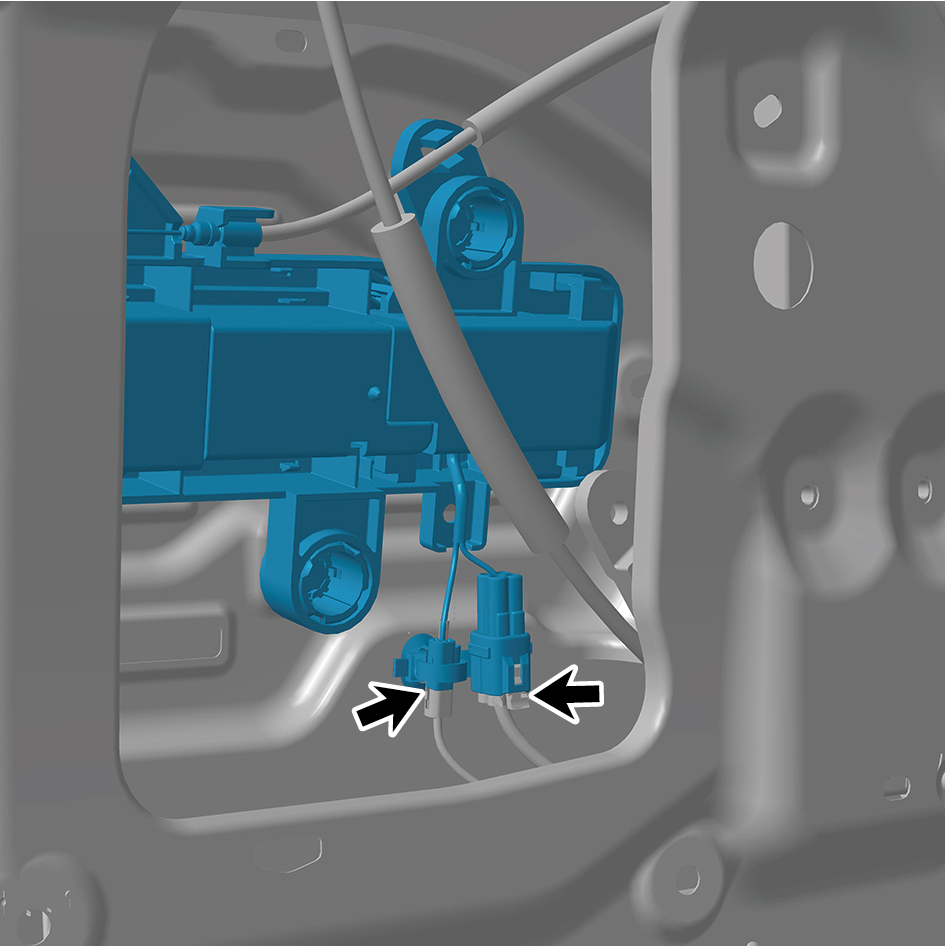
handle assembly.
8
Disengage 3 clips of the hidden outside handle assembly.
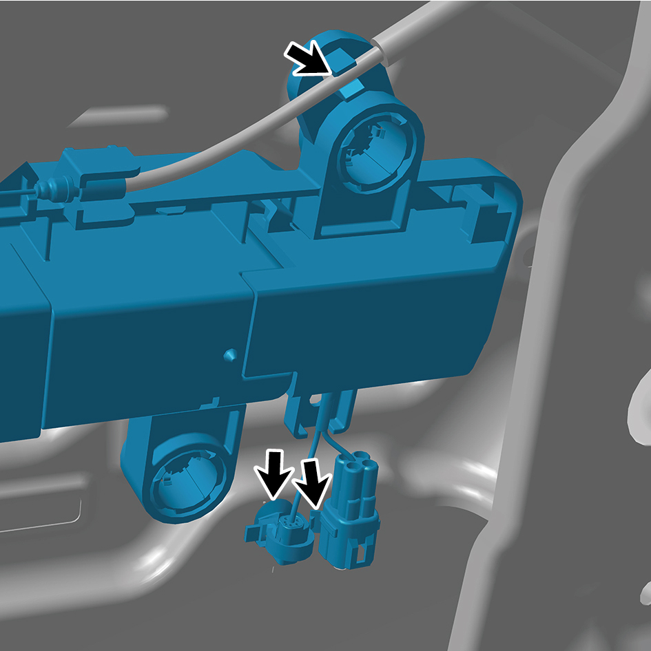
9
Disengage 2 cables of the hidden outside handle
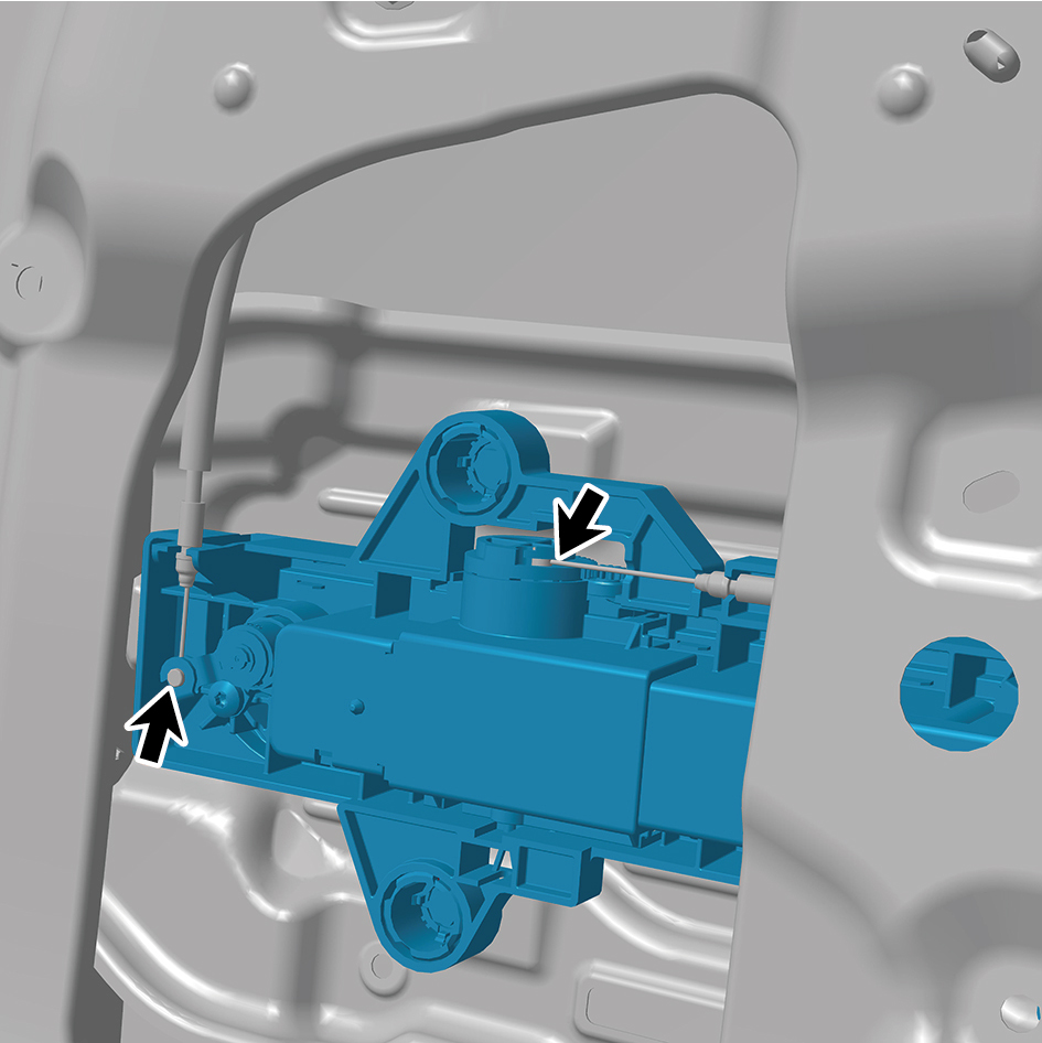
assembly.
10
Remove 4 fixing screws of the hidden outside handle
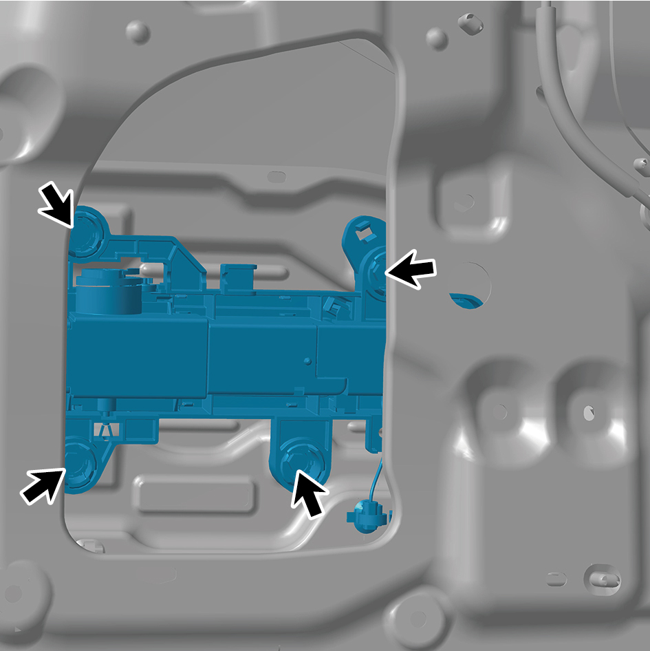
assembly.
11
Remove the hidden outside handle assembly.
Installation Procedures
1
Move the hidden outside handle assembly to the mounting
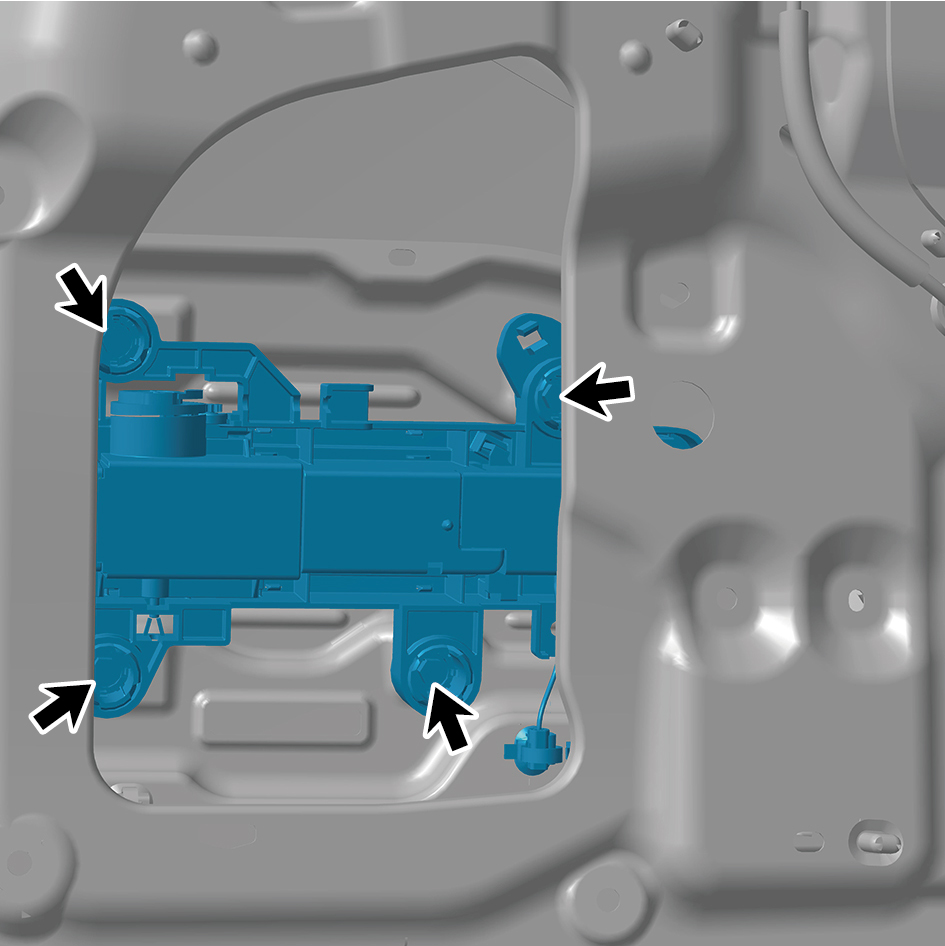
position.
2
Install 4 fixing screws of the hidden outside handle
assembly.
3
Connect 2 cables of the hidden outside handle assembly.
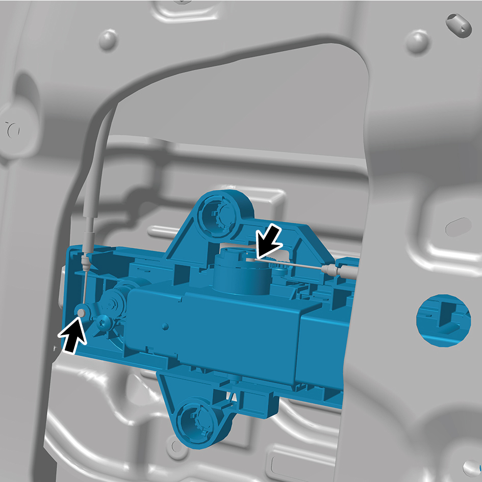
4
Install 3 clips of the hidden outside handle assembly.
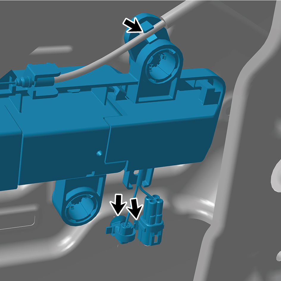
5
Connect 2 harness connectors of the hidden outside
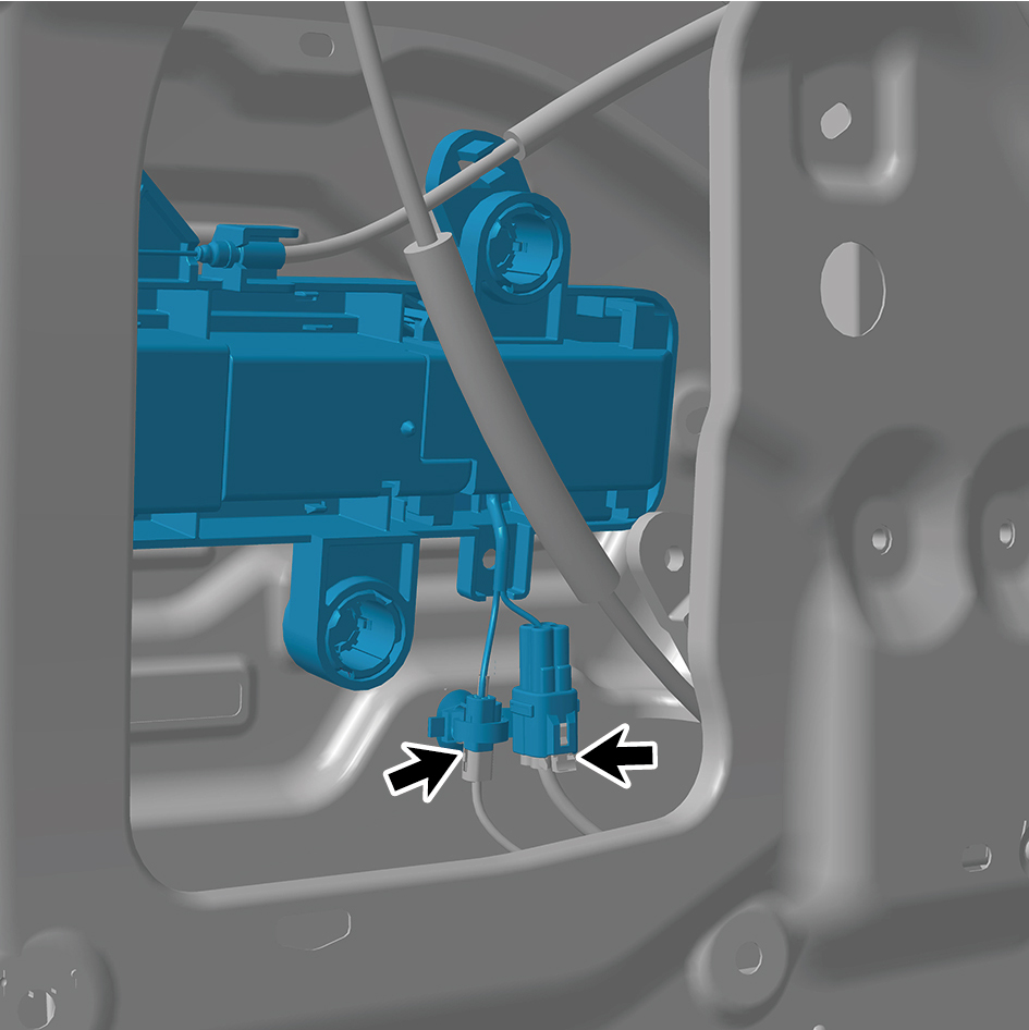
handle assembly.
caution
The harness is firmly connected following the
principal of "insert until a click is heard for
confirmation".
6
Install the right body waterproof membrane (II).
7
Install the door protective plate assembly.
8
Install the cable cover plate.
9
Connect the battery negative cable.
10
Close the front flip cover plate.
11
Close the door.
6.32.5.2 Replacement of Rear Lock Assembly
Removal Procedures
1
Open the door.
2
Open the front flip cover plate.
3
Disconnect the battery negative cable.
caution
power down the high-voltage system before
disconnecting the negative pole of the storage
battery.
4
Remove the cable cover plate.
5
Remove the door protective plate assembly.
6
Remove the right body waterproof membrane (Ⅰ).
7
Remove the right body waterproof membrane (II).
8
Remove the door inside handle assembly.
9
Remove the hidden outside handle assembly.
10
Remove the ground lock assembly.
11
Disconnect 1 harness connector of the rear lock
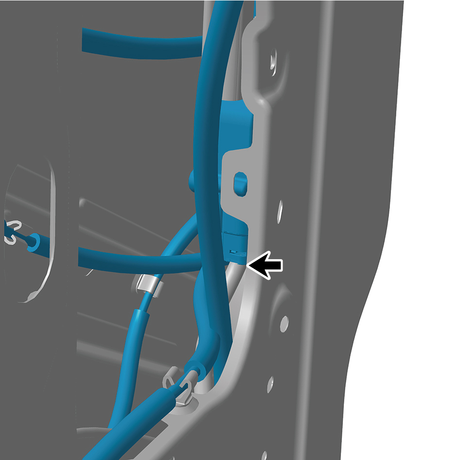
assembly.
12
Disengage 5 clips of the rear lock assembly.
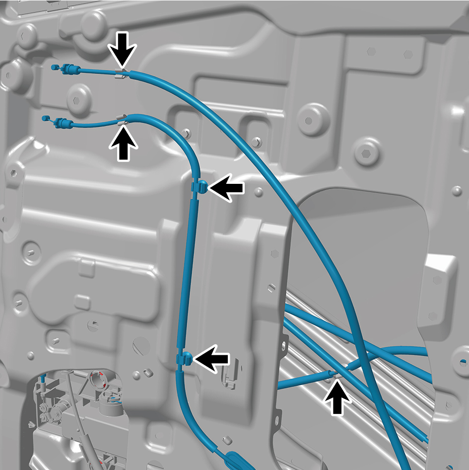
13
Disengage 4 cables of the rear lock assembly.
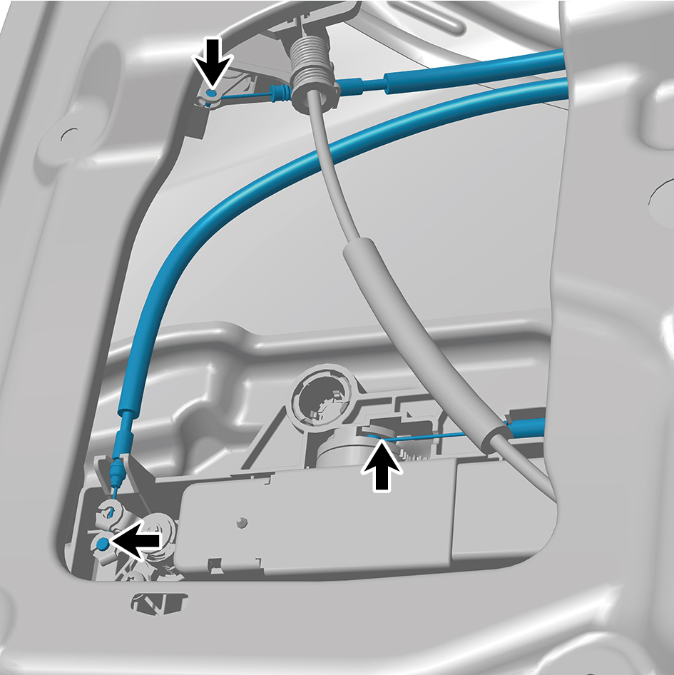
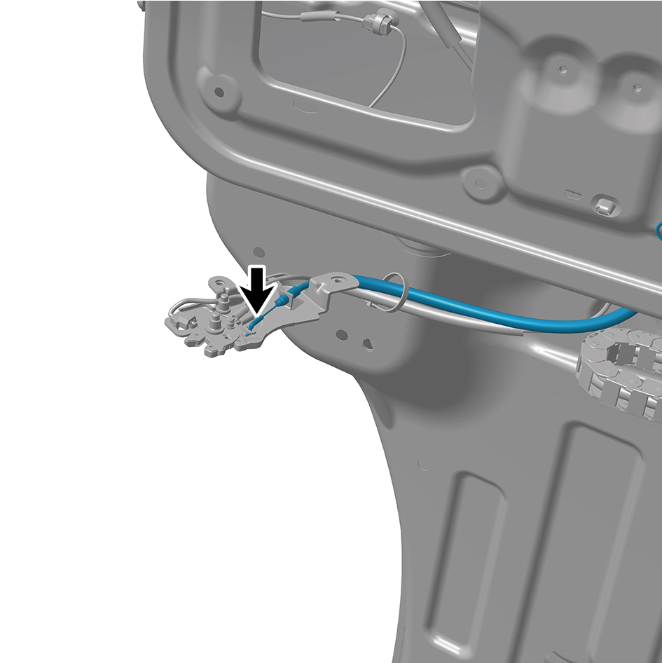
14
Disengage 6 clips of the rear lock assembly.
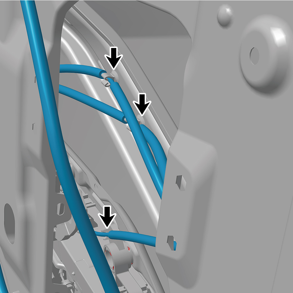
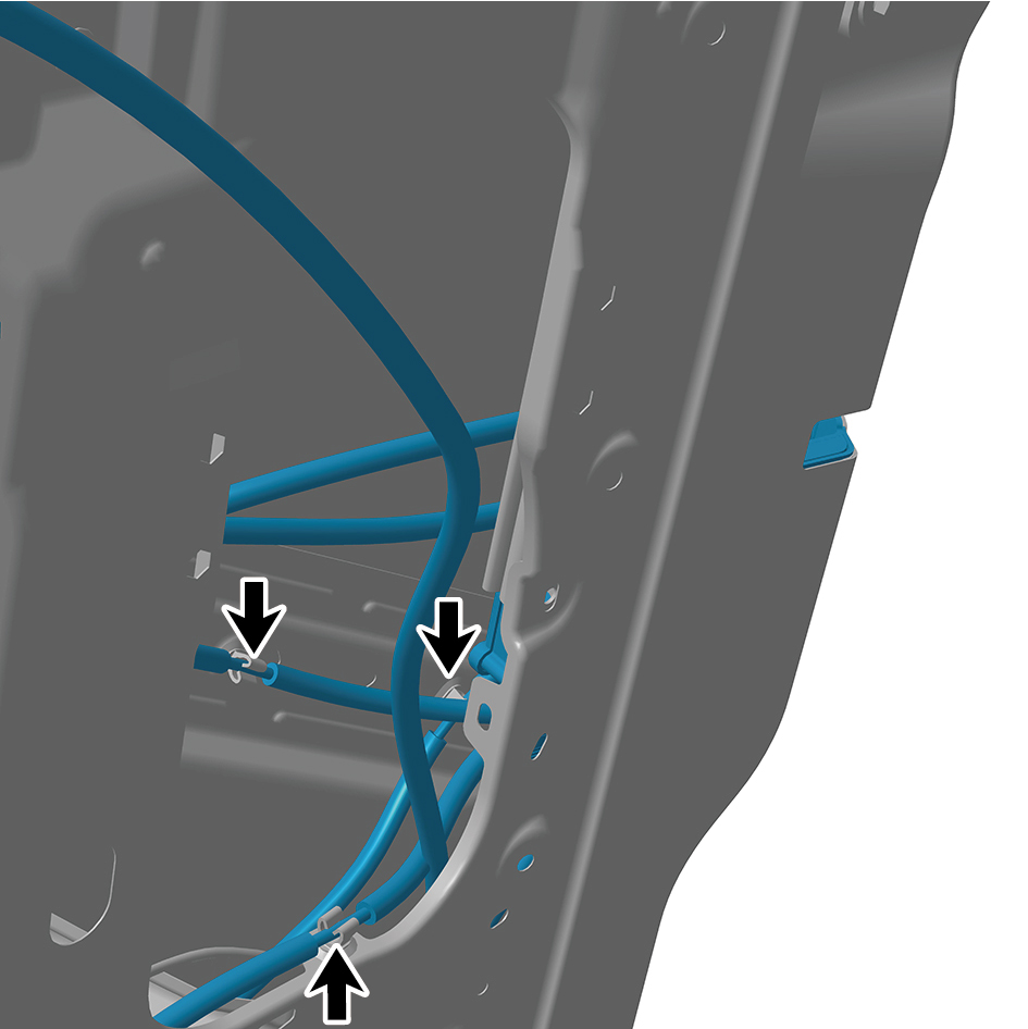
15
Remove 3 fixing screws of the rear lock assembly.
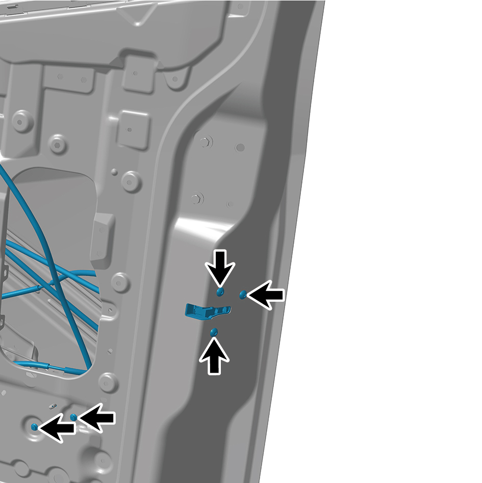
16
Remove 2 fixing bolts of the rear lock assembly.
17
Remove the rear lock assembly.
Installation Procedures
1
Move the rear lock assembly to the mounting position.
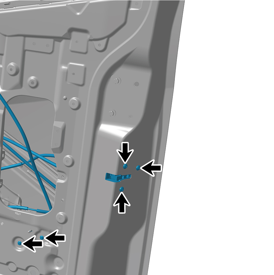
2
Install 2 fixing bolts of the rear lock assembly.
Torque:(6.5 +/- .75) ft lbs
3
Install 3 fixing screws of the rear lock assembly.
4
Install 6 clips of the rear lock assembly.
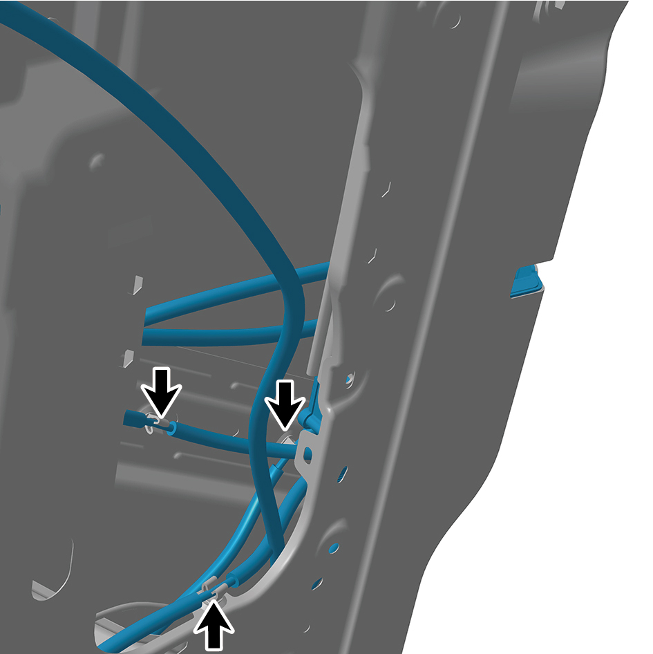
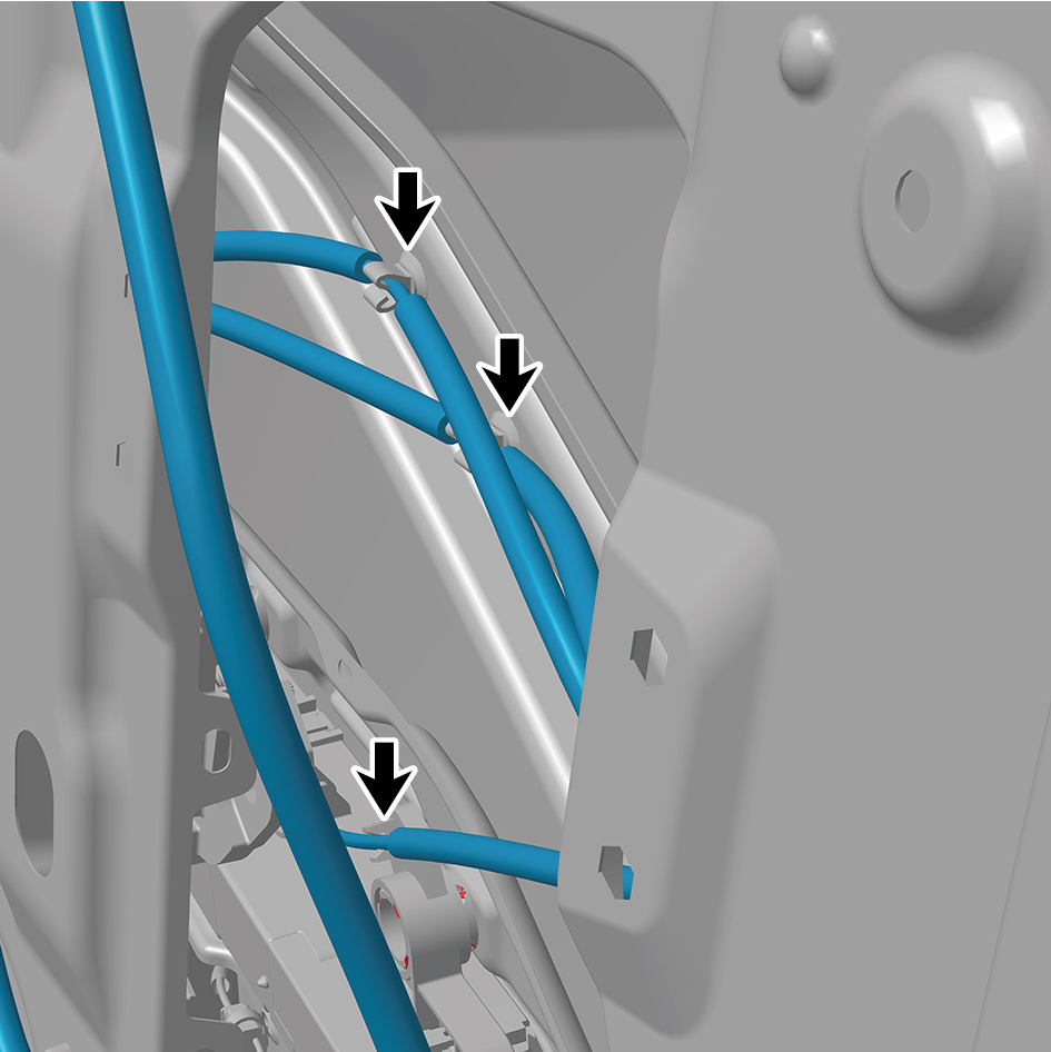
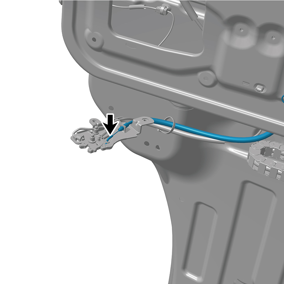
5
Connect 4 cables of the rear lock assembly.
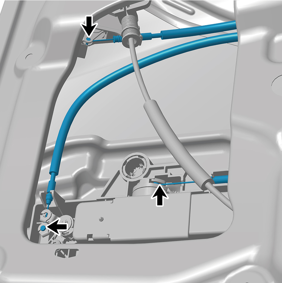
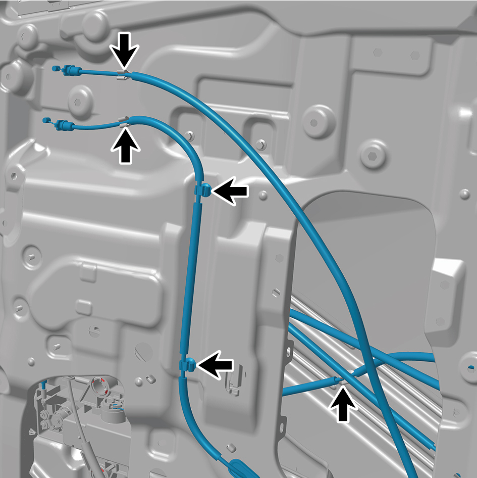
6
Install 5 clips of the rear lock assembly.
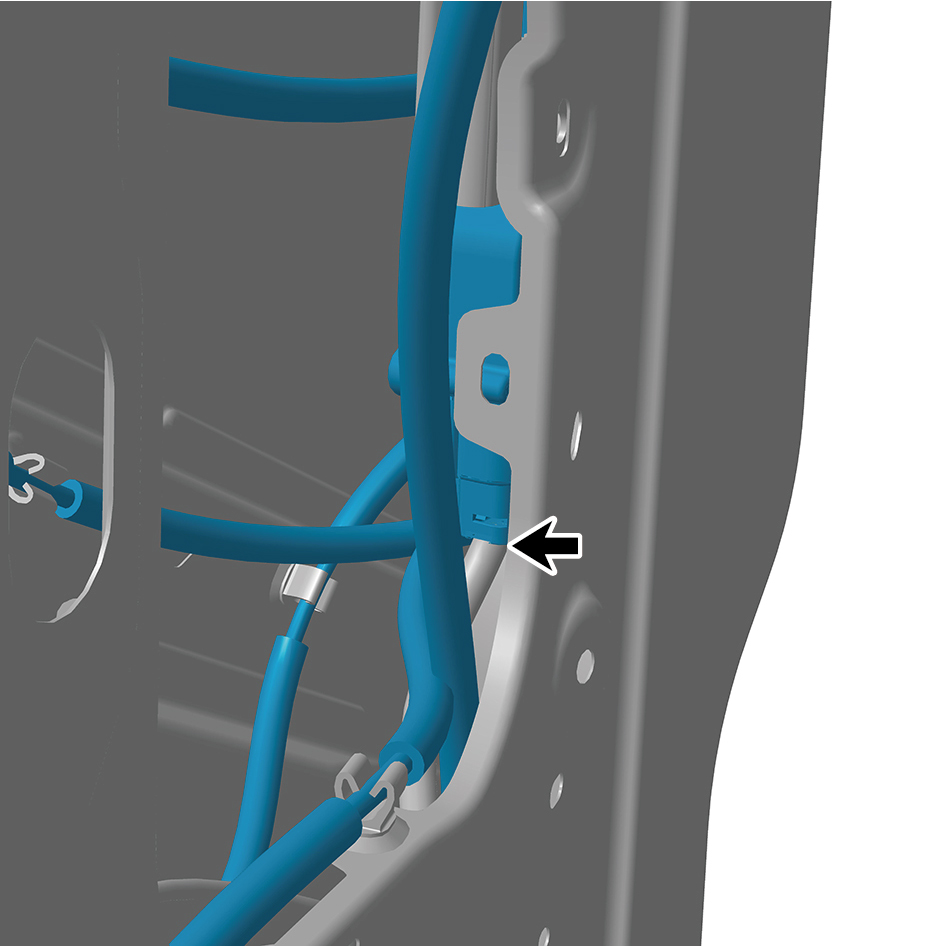
7
Connect 1 harness connector of the rear lock assembly.
caution
The harness is firmly connected following the
principal of "insert until a click is heard for
confirmation".
8
Install the ground lock assembly.
9
Install the hidden outside handle assembly.
10
Install the door inside handle assembly.
11
Install the right body waterproof membrane (II).
12
Install the right body waterproof membrane (Ⅰ).
13
Install the door protective plate assembly.
14
Install the cable cover plate.
15
Connect the battery negative cable.
16
Close the front flip cover plate.
17
Close the door.
6.32.5.3 Replacement of Front Lock Assembly
Removal Procedures
1
Open the door.
2
Remove the cable cover plate.
3
Remove the door protective plate assembly.
4
Remove the right body waterproof membrane (II).
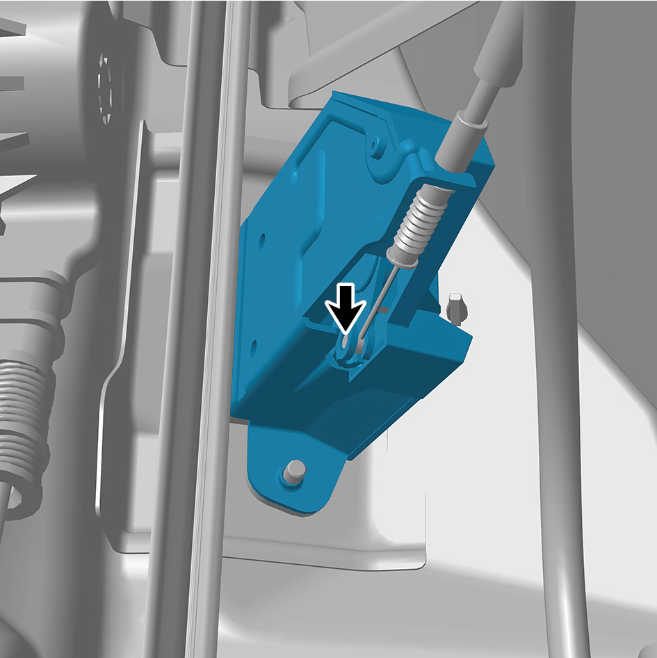
5
Disengage 1 cable of the front lock assembly.
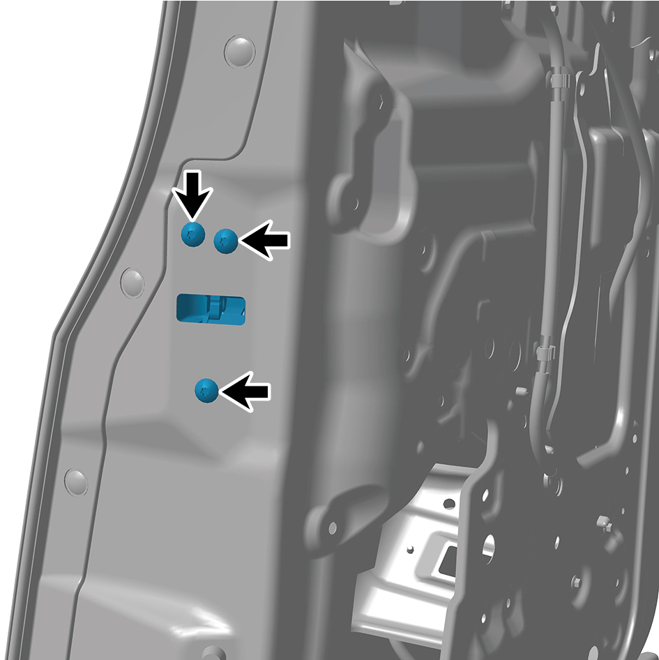
6
Remove 3 fixing screws of the front lock assembly.
7
Remove the front lock assembly.
Installation Procedures
1
Move the front lock assembly to the mounting position.
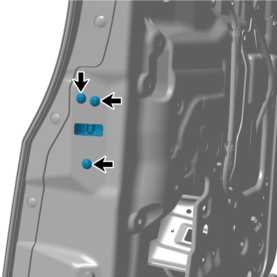
2
Install 3 fixing screws of the front lock assembly.
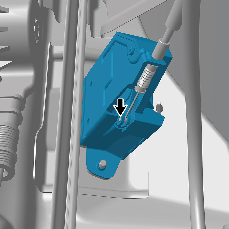
3
Connect 1 cable of the front lock assembly.
4
Install the right body waterproof membrane (II).
5
Install the door protective plate assembly.
6
Install the cable cover plate.
7
Close the door.
6.32.5.4 Replacement of Sliding Door Driver Assembly
Assembly
Removal Procedures
1
Open the door.
2
Open the front flip cover plate.
3
Disconnect the battery negative cable.
caution
power down the high-voltage system before
disconnecting the negative pole of the storage
battery.
4
Remove the right sill molding assembly.
5
Remove the door opening sealing strip assembly.
6
Remove the safety hammer fixing bracket.
7
Remove the rear boarding handrail assembly.
8
Remove the SSM.
9
Remove the right rear side wall protective plate assembly.
10
Remove the right side wall slide rail cover plate assembly.
11
Remove the right side wall slide rail end cover plate
assembly.
12
Disconnect 1 harness connector of the sliding door driver
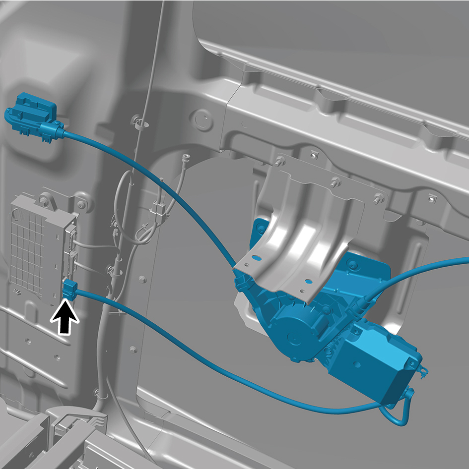
assembly.
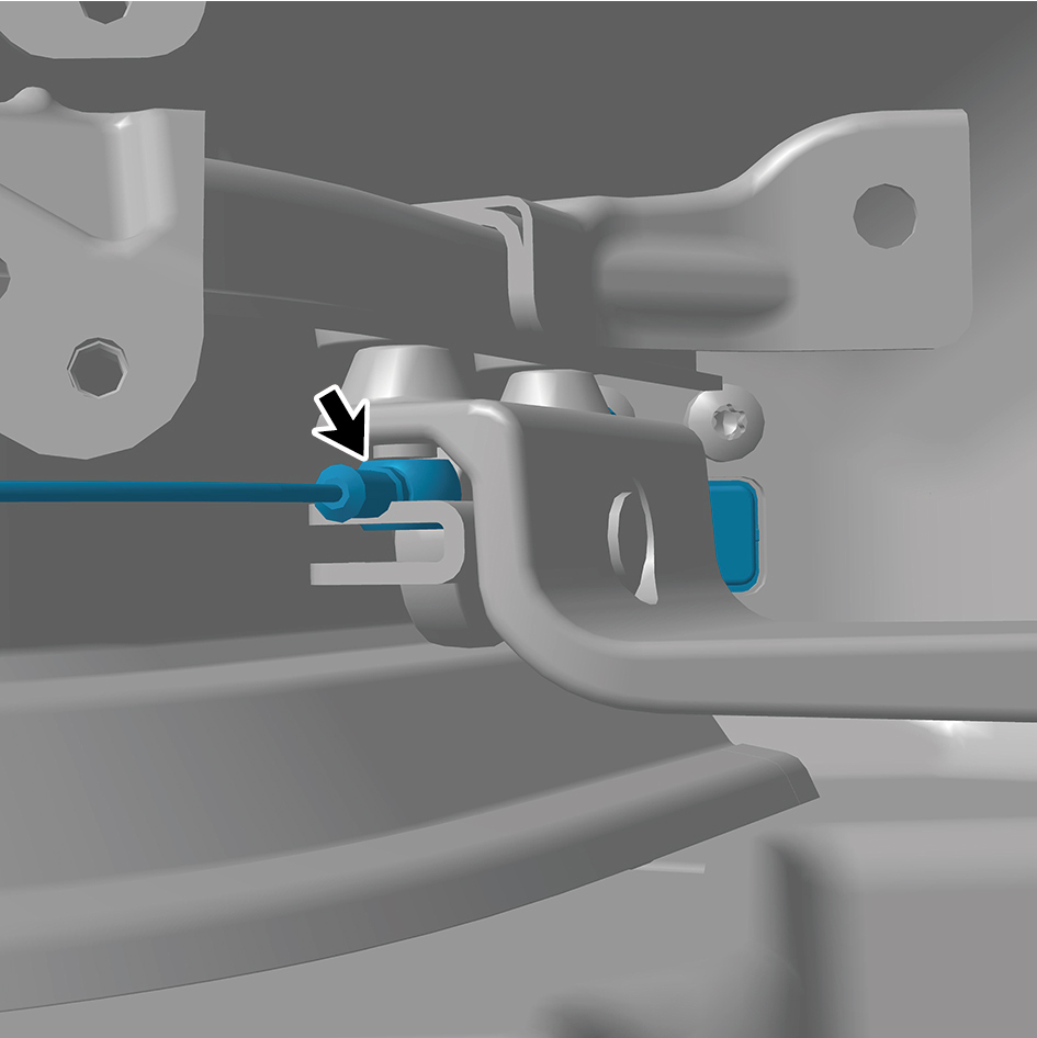
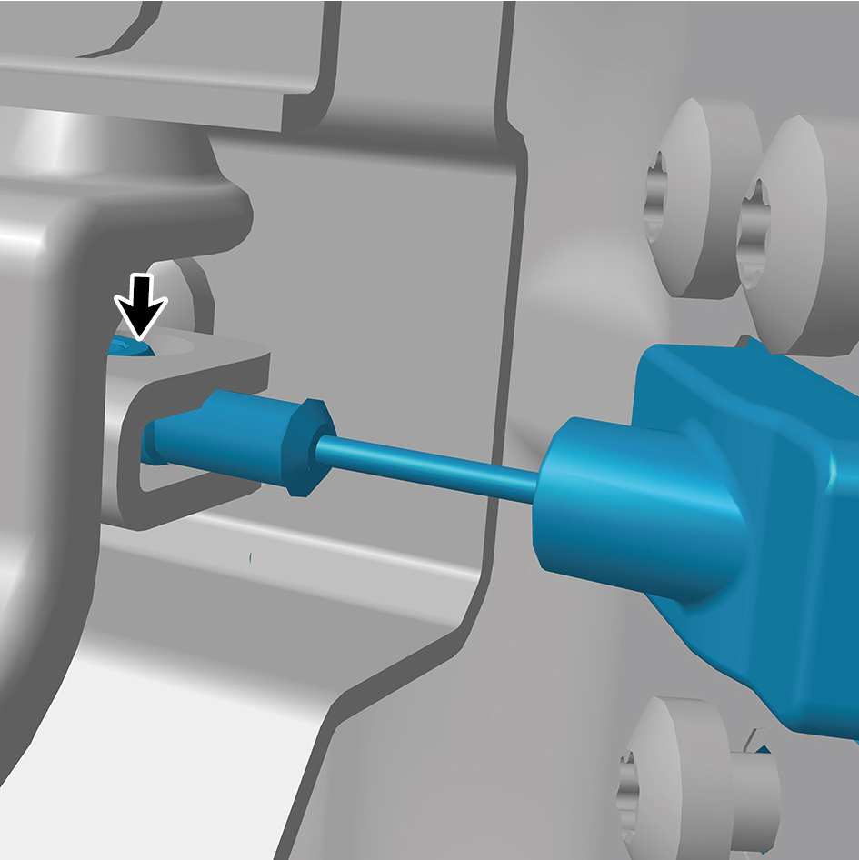
13
Disengage 2 cables of the sliding door driver assembly.
14
Remove 4 fixing screws of the sliding door driver
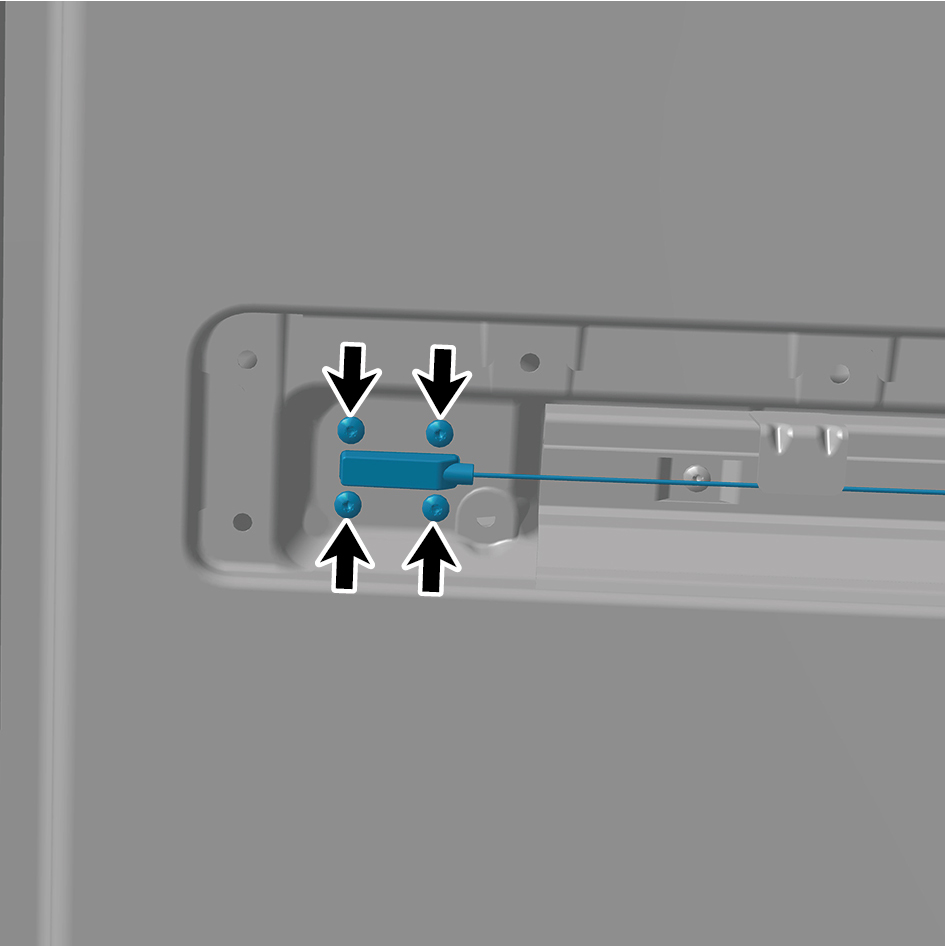
assembly.
15
Remove 6 fixing screws of the sliding door driver
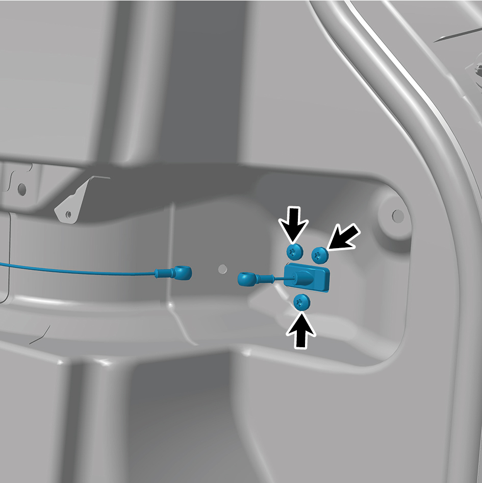
assembly, and remove the sliding door driver assembly.
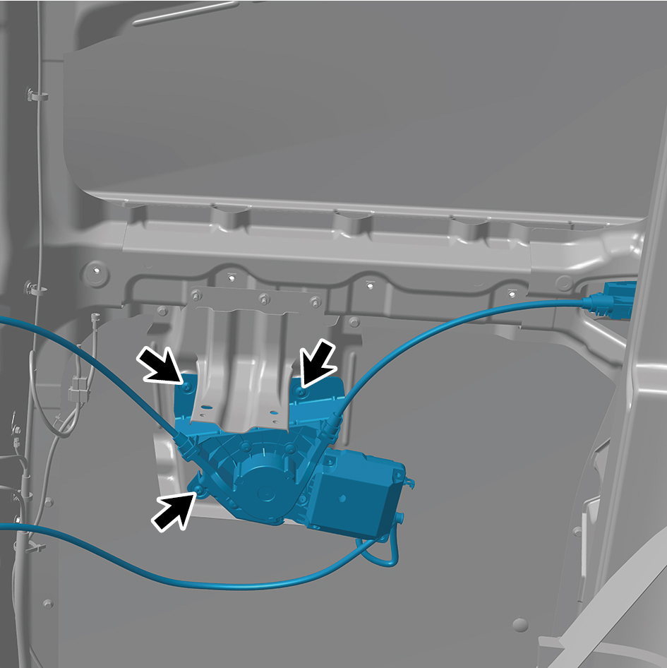
Installation Procedures
1
Move the sliding door driver assembly to the mounting
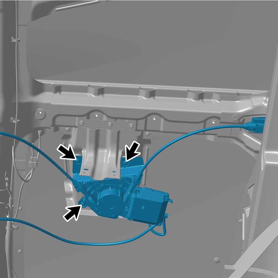
position.
2
Install 6 fixing screws of the sliding door driver assembly.
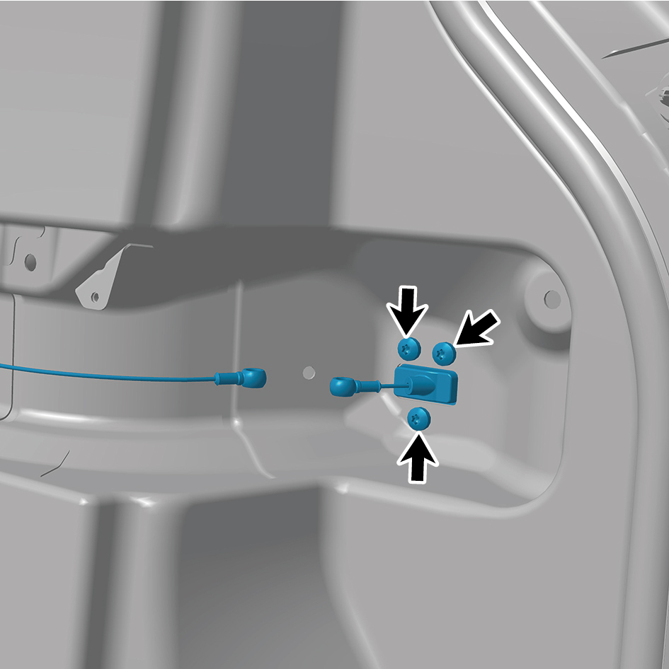
3
Install 4 fixing screws of the sliding door driver assembly.
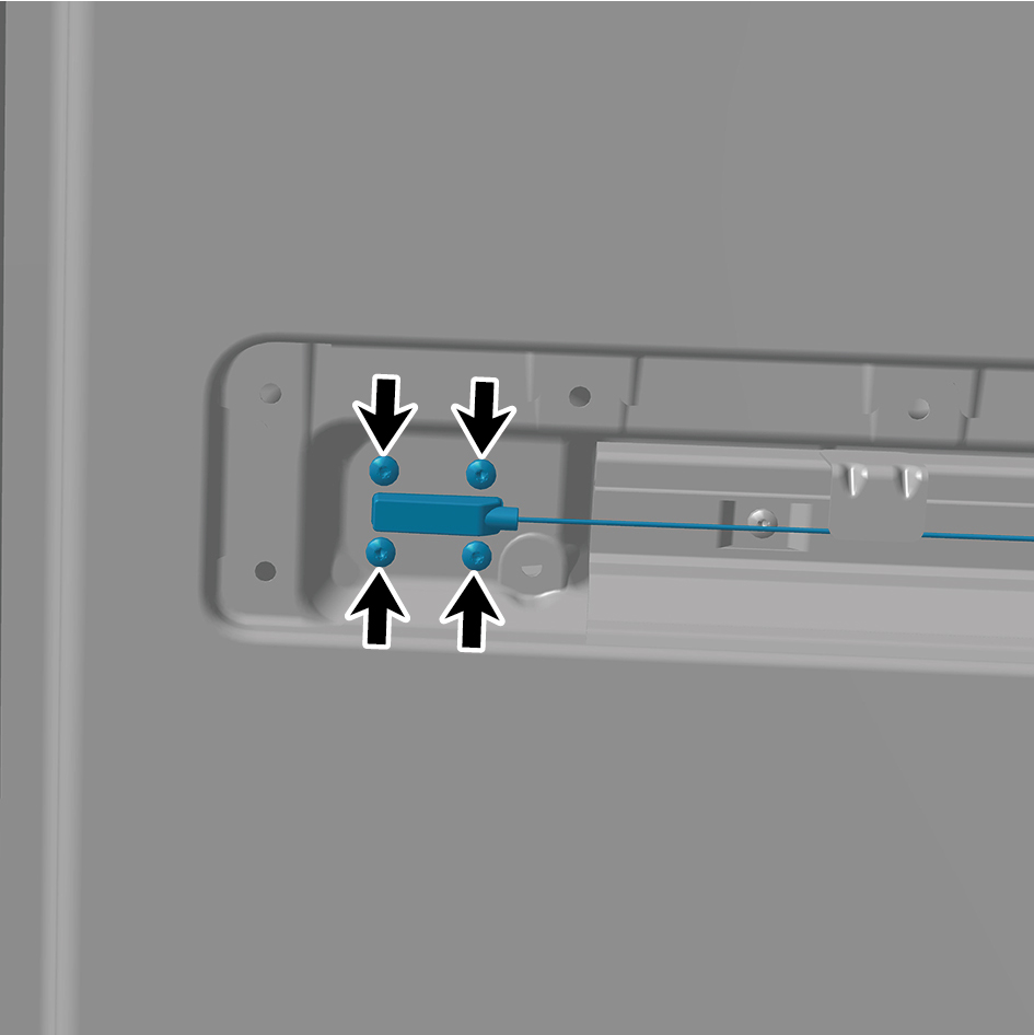
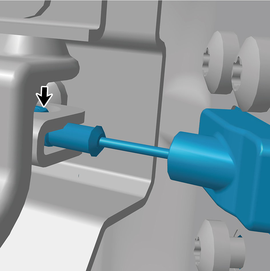
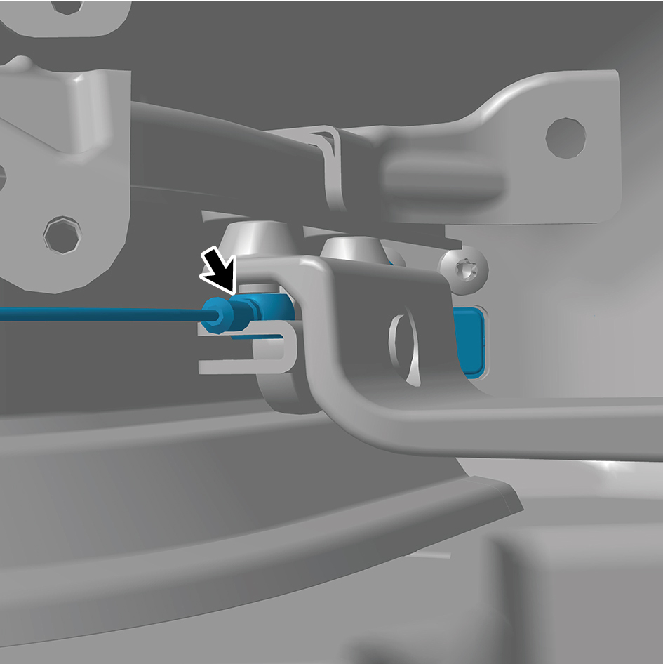
4
Connect 2 cables of the sliding door driver assembly.
5
Connect 1 harness connector of the sliding door driver
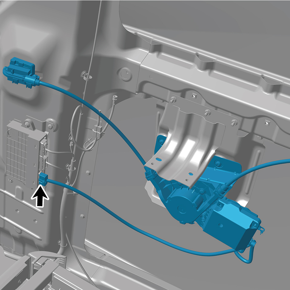
assembly.
caution
The harness is firmly connected following the
principal of "insert until a click is heard for
confirmation".
6
Install the right side wall slide rail end cover plate
assembly.
7
Install the right side wall slide rail cover plate assembly.
8
Install the right rear side wall protective plate assembly.
9
Install the SSM.
10
Install the rear boarding handrail assembly.
11
Install the safety hammer fixing bracket.
12
Install the door opening sealing strip assembly.
13
Install the right sill molding assembly.
14
Connect the battery negative cable.
15
Close the front flip cover plate.
16
Close the door.
6.32.5.5 Replacement of Lock Cylinder Assembly
Assembly
Removal Procedures
1
Open the door.
2
Remove the cable cover plate.
3
Remove the door protective plate assembly.
4
Remove the right body waterproof membrane (II).
5
Disengage 1 cable of the lock cylinder assembly.
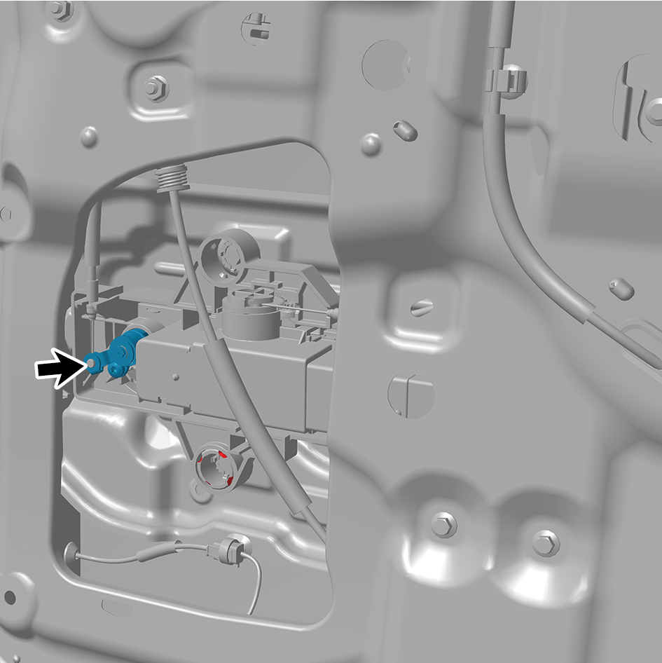
6
Remove 1 fixing screw of the lock cylinder assembly.

7
Remove the lock cylinder assembly.
Installation Procedures
1
Move the lock cylinder assembly to the mounting position.
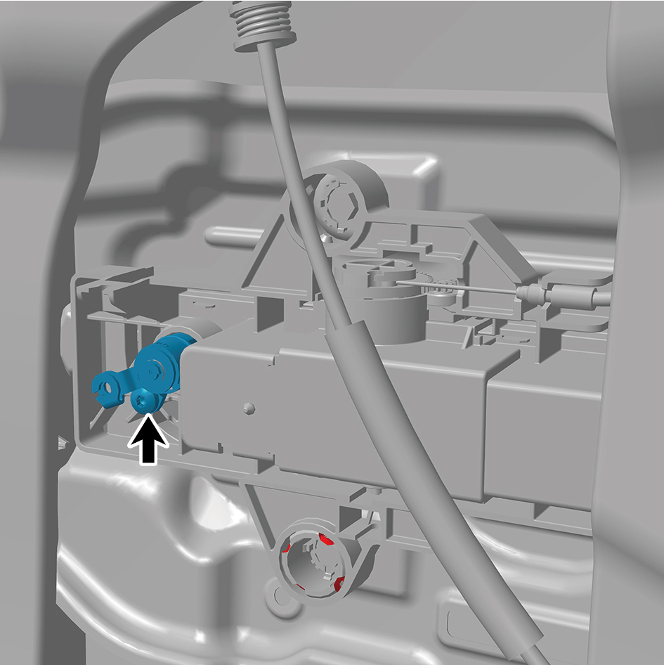
2
Install 1 fixing screw of the lock cylinder assembly.
3
Connect 1 cable of the lock cylinder assembly.
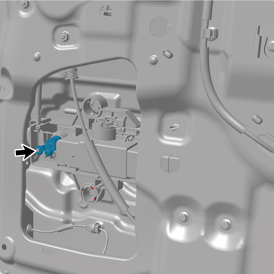
4
Install the right body waterproof membrane (II).
5
Install the door protective plate assembly.
6
Install the cable cover plate.
7
Close the door.
6.32.5.6 Replacement of Ground Lock Assembly
Assembly
Removal Procedures
1
Open the door.
2
Open the front flip cover plate.
3
Disconnect the battery negative cable.
caution
power down the high-voltage system before
disconnecting the negative pole of the storage
battery.
4
Remove the cable cover plate.
5
Remove the door protective plate assembly.
6
Remove the right body waterproof membrane (II).
7
Remove 2 fixing nuts of the ground lock assembly.
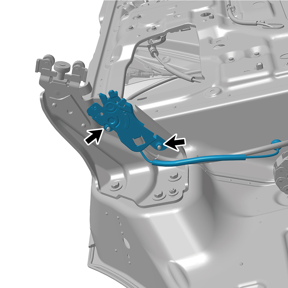
8
Disconnect 1 harness connector of the ground lock
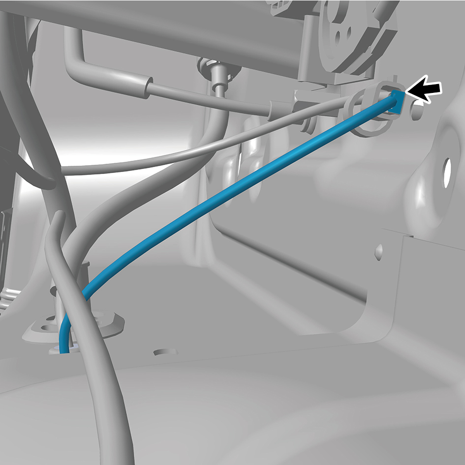
assembly.
9
Disengage 1 cable of the ground lock assembly.
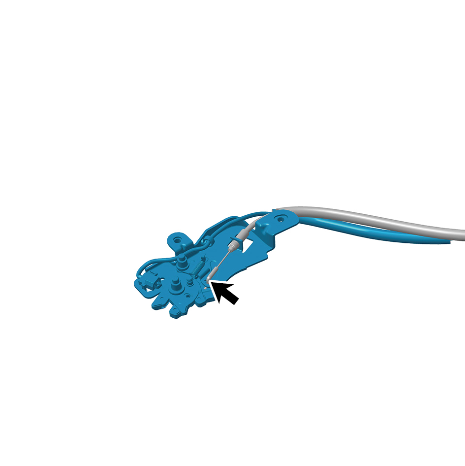
10
Remove the ground lock assembly.
Installation Procedures
1
Move the ground lock assembly to the mounting position.
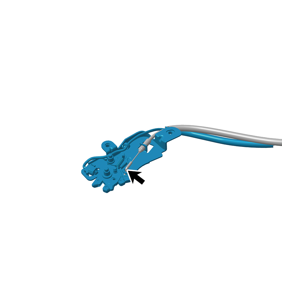
2
Connect 1 cable of the ground lock assembly.
3
Connect 1 harness connector of the ground lock
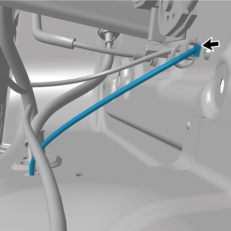
assembly.
caution
The harness is firmly connected following the
principal of "insert until a click is heard for
confirmation".
4
Install 2 fixing nuts of the ground lock assembly.
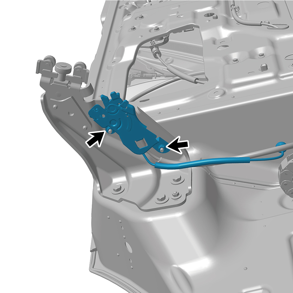
Torque:(6.5 +/- .75) ft lbs
5
Install the right body waterproof membrane (II).
6
Install the door protective plate assembly.
7
Install the cable cover plate.
8
Connect the battery negative cable.
9
Close the front flip cover plate.
10
Close the door.
6.32.5.7 Replacement of Ground Lock Catch Assembly
Assembly
Removal Procedures
1
Open the door.
2
Remove the right side wall lower trim panel assembly.
3
Remove 4 fixing bolts of the ground lock catch assembly.
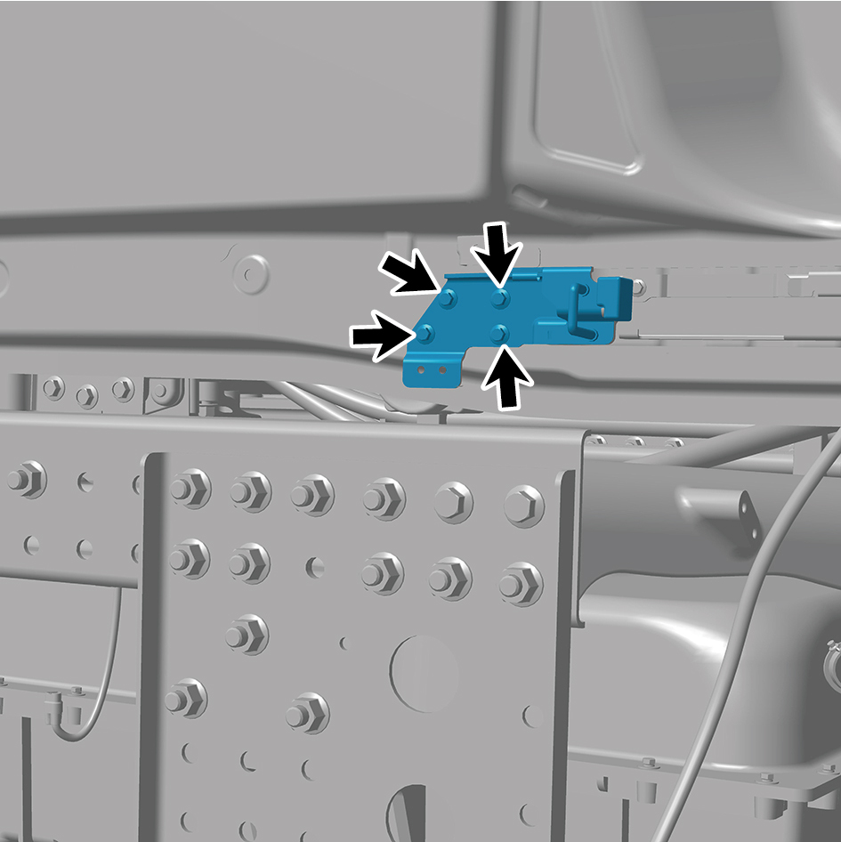
4
Remove the ground lock catch assembly.
Installation Procedures
1
Move the ground lock catch assembly to the mounting
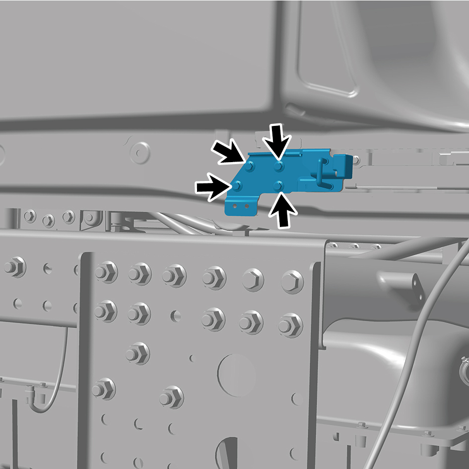
position.
2
Install 4 fixing bolts of the ground lock catch assembly.
Torque: (6.5 +/- .75) ft lbs
3
Attach the right side wall lower trim panel assembly.
4
Close the door.