← Back to Contents
6 Vehicle Body / 6.31 Window Regulator Device | PDF pages 884-892
6.31 Window Regulator Device
6.31 Window Regulator Device
6.31.1 Specifications
6.31.1.1 Fastener Specifications
Range Of Torque
Fastener Specifications
Specifications
Foot Pounds of Torque (ft lbs)
The fixing nut connecting the right
window regulator assembly and the
(6.5 +/- .75) ft lbs
M6
door trim assembly
The fixing nut connecting the left
window regulator assembly and the
(6.5 +/- .75) ft lbs
M6
door trim assembly
6.31.2 Decomposition Diagram
6.31.2.1 Decomposition Diagram
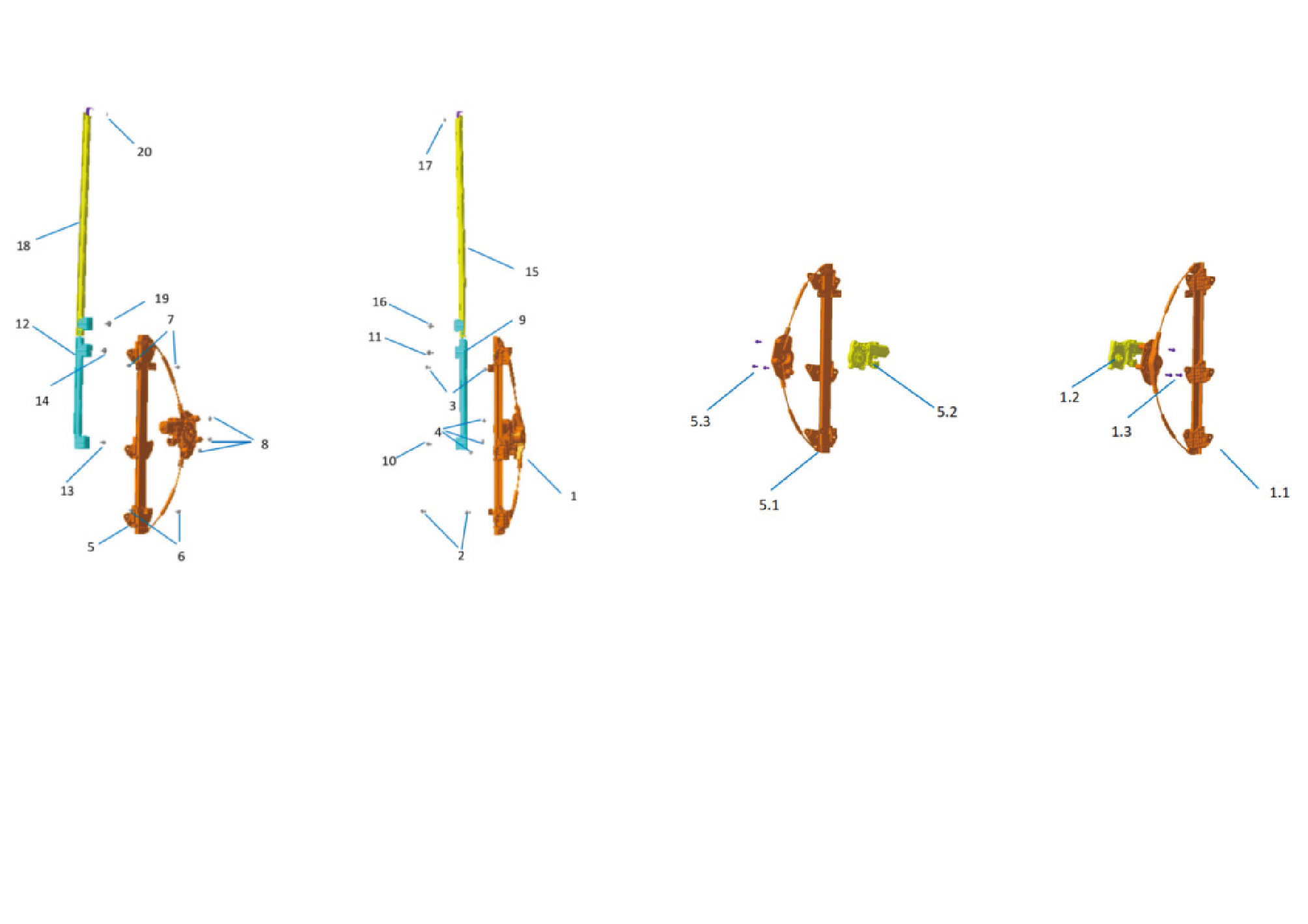
1.
Window Regulator-Rh
8.
Hexagon Flange Nut
1.1.
9.
Assembly of the Left Window Regulator Guide Rail
Window Regulator Mount Guide Rail Assy-Lh Lower
1.2.
10.
Hexagon Flange Bolt
Assembly of the Left Window Regulator Motor
1.3.
11.
Hexagon Head Bolt Assy
Self-Tapping Screw
2.
Hexagon Flange Bolt
12.
Window Regulator Mount Guide Rail Assy-Rh Lower
3.
Hexagon Flange Bolt
13.
Hexagon Flange Bolt
4.
Hexagon Flange Nut
14.
Hexagon Head Bolt Assy
5.
Window Regulator-Rh
15.
Window Regulator Mount Guide Rail-Rh
5.1.
16.
Hexagon Head Bolt Assy
Assembly of the Right Window Regulator Guide Rail
5.2.
17.
Assembly of the Right Window Regulator Motor
Hex Socket Set Screw
5.3.
18.
Self-Tapping Screw
Window Regulator Mount Guide Rail-Rh
6.
Hexagon Flange Bolt
19.
Hexagon Head Bolt Assy
7.
Hexagon Flange Bolt
20.
Hex Socket Set Screw
6.31.3 Dismantling and Installation
6.31.3.1 Replacement of Left Window Regulator Assembly
Regulator Assembly
Removal Procedures
1
Open the door.
2
Open the front flip cover plate.
3
Disconnect the battery negative cable.
caution
power down the high-voltage system before
disconnecting the negative pole of the storage
battery.
4
Remove the IP left upper trim panel assembly.
5
Remove the left A-pillar protective plate assembly.
6
Remove the left front side wall protective plate assembly.
7
Remove the front USB interface.
8
Remove the IP left access cover plate assembly.
9
Remove the left switch panel assembly.
10
Remove the left switch panel lower trim panel assembly.
11
Remove the IP left lower trim panel assembly.
12
Remove the left middle side wall lower trim panel
assembly.
13
Remove the left middle side wall middle trim panel
assembly.
caution
1.First remove the break glass hammer's zipper
cover, carefully take out the break glass hammer's
pull ring and place it inside the trim panel.
2.Be careful to avoid accidentally pulling the break
glass hammer's pull ring.
14
Remove the left body waterproof membrane (Ⅰ).
15
Disconnect 1 harness connector of the left window
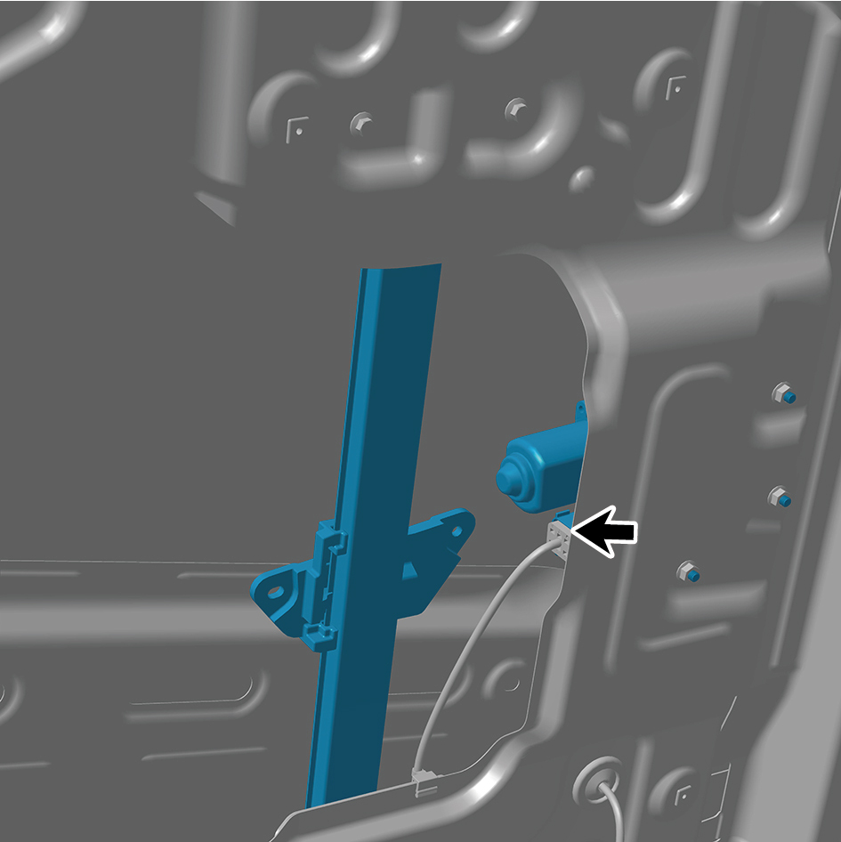
regulator assembly.
16
Remove 3 fixing nuts of the left window regulator
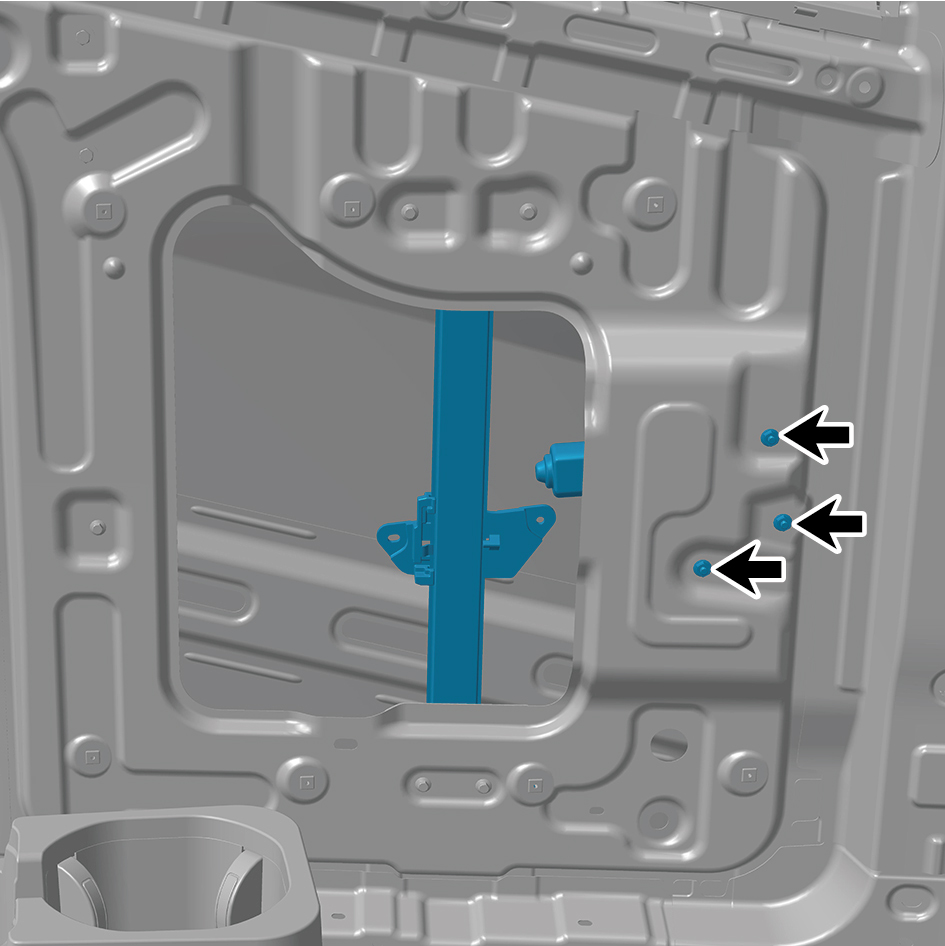
assembly.
17
Remove 4 fixing bolts of the left window regulator
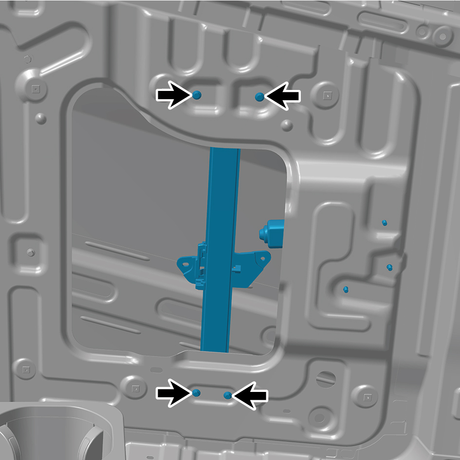
assembly.
18
Remove the left window regulator assembly.
Installation Procedures
1
Move the left window regulator assembly to the mounting
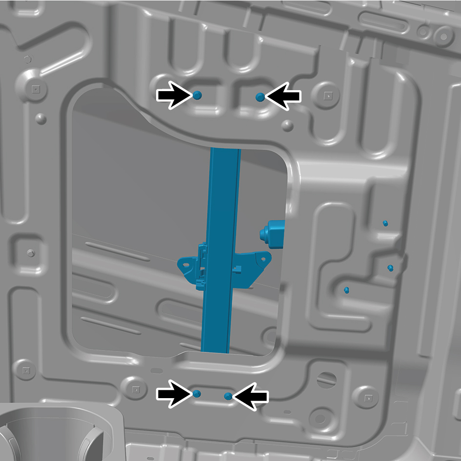
position.
2
Install 4 fixing bolts of the left window regulator assembly.
Torque: (6.5 +/- .75) ft lbs
3
Install 3 fixing nuts of the left window regulator assembly.
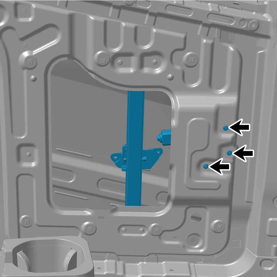
Torque: (6.5 +/- .75) ft lbs
4
Connect 1 harness connector of the left window regulator
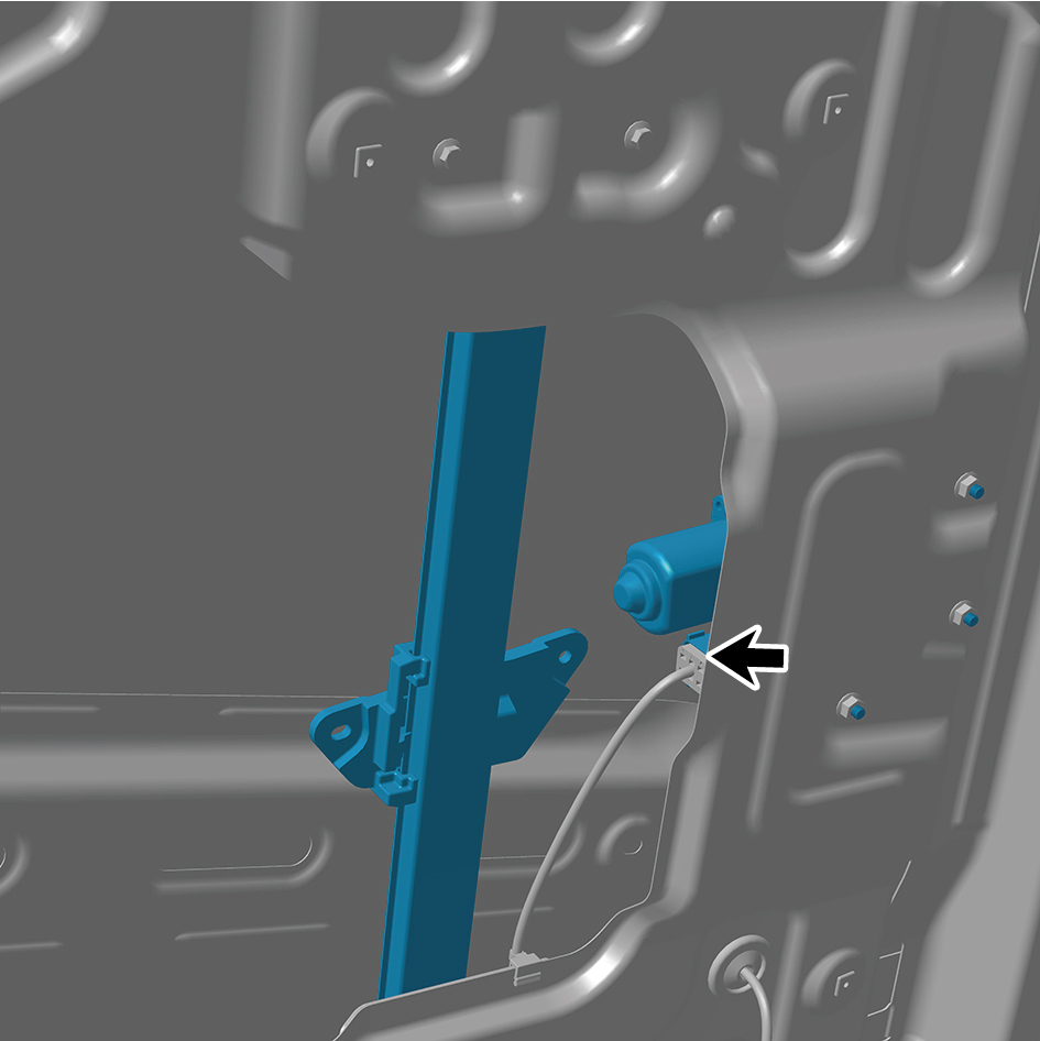
assembly.
caution
The harness is firmly connected following the
principal of "insert until a click is heard for
confirmation".
5
Install the left body waterproof membrane (Ⅰ).
6
Install the left middle side wall middle trim panel assembly.
7
Install the left middle side wall lower trim panel assembly.
8
Install the IP left lower trim panel assembly.
9
Install the left switch panel lower trim panel assembly.
10
Install the left switch panel assembly.
11
Install the IP left access cover plate assembly.
12
Install the front USB interface.
13
Install the left front side wall protective plate assembly.
14
Install the left A-pillar protective plate assembly.
15
Install the IP left upper trim panel assembly.
16
Connect the battery negative cable.
17
Close the front flip cover plate.
18
Close the door.
6.31.3.2 Replacement of Right Window Regulator Assembly
Regulator Assembly
Removal Procedures
1
Open the door.
2
Open the front flip cover plate.
3
Disconnect the battery negative cable.
caution
power down the high-voltage system before
disconnecting the negative pole of the storage
battery.
4
Remove the cable cover plate.
5
Remove the door protective plate assembly.
6
Remove the right body waterproof membrane (Ⅰ).
7
Remove the right body waterproof membrane (II).
8
Disconnect 1 harness connector of the right window
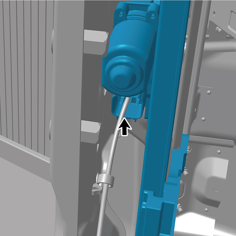
regulator assembly.
9
Remove 3 fixing nuts of the right window regulator
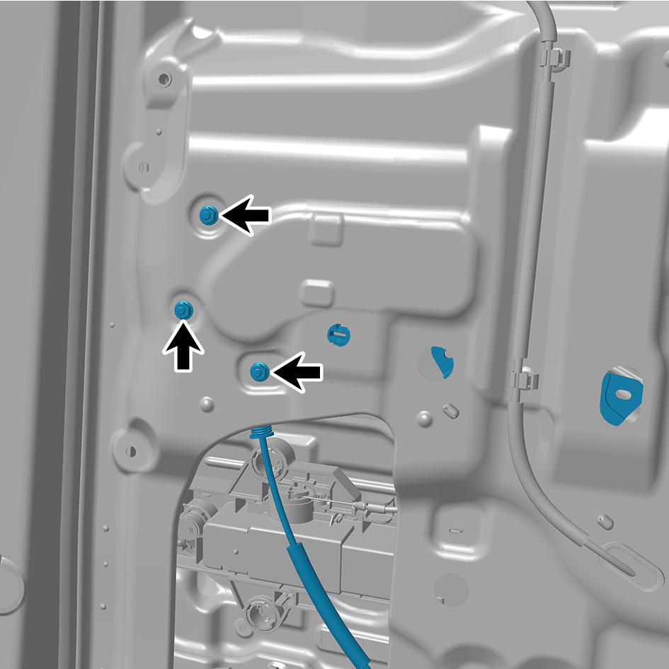
assembly.
10
Remove 4 fixing bolts of the right window regulator
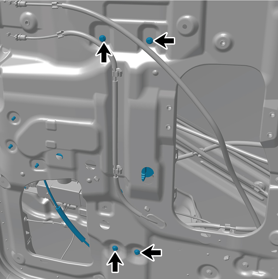
assembly.
11
Remove the right window regulator assembly.
Installation Procedures
1
Move the right window regulator assembly to the mounting
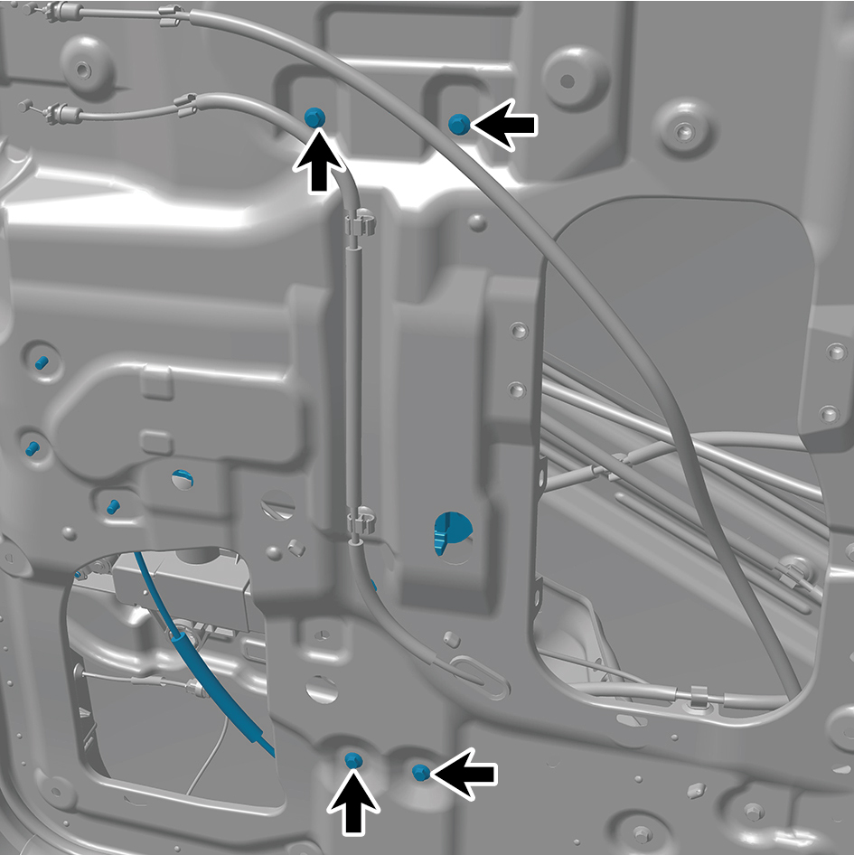
position.
2
Install 4 fixing bolts of the right window regulator assembly.
Torque: (6.5 +/- .75) ft lbs
3
Install 3 fixing nuts of the right window regulator assembly.
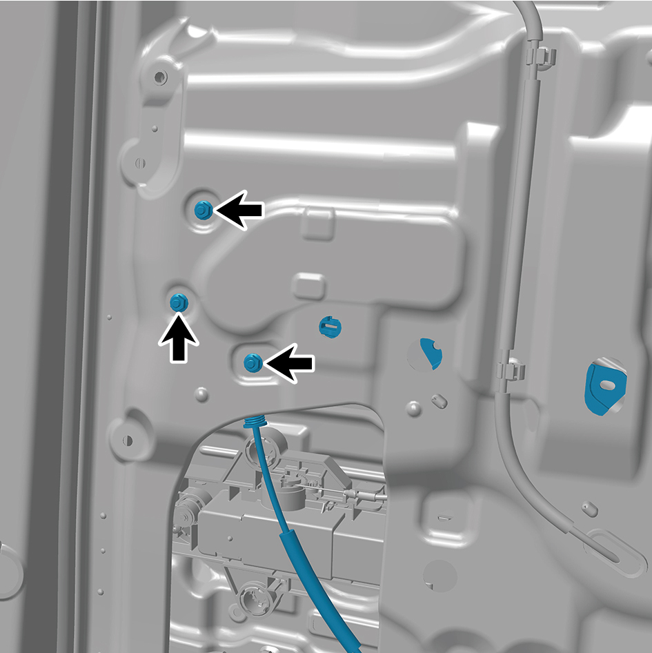
Torque: (6.5 +/- .75) ft lbs
4
Connect 1 harness connector of the right window regulator
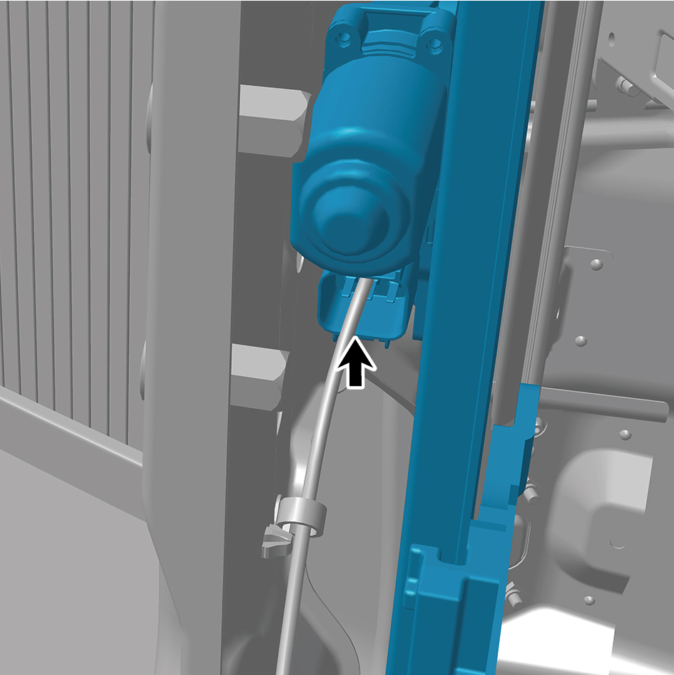
assembly.
caution
The harness is firmly connected following the
principal of "insert until a click is heard for
confirmation".
5
Install the right body waterproof membrane (II).
6
Install the right body waterproof membrane (Ⅰ).
7
Install the door protective plate assembly.
8
Install the cable cover plate.
9
Connect the battery negative cable.
10
Close the front flip cover plate.
11
Close the door.