← Back to Contents
6 Vehicle Body / 6.11 Dashboard Device | PDF pages 623-738
6.11 Dashboard Device
6.11 Dashboard Device
6.11.1 Specifications
6.11.1.1 Fastener Specifications
Range Of Torque
Fastener Specifications
Specifications
Metric System(ft-lb)
The fixing bolts connecting the pipe
beam assembly and the white body
(18 ft-lb +/- 2 ft-lb) ft-lb
M8
assembly assembly
Fixed bolts connecting the pipe beam
assembly and HVAC assembly
(6.5 ft-lb +/- .75 ft-lb) ft-lb
M6
(including PTC)
The fixing bolt connecting the left lower
trim assembly of the dashboard to the
(6.5 ft-lb +/- .75 ft-lb) ft-lb
M6
left lower fixing bracket
The fixing bolt between the right storage
box assembly and the storage box
(6.5 ft-lb +/- .75 ft-lb) ft-lb
M6
bracket assembly
6.11.2 Decomposition Diagram
6.11.2.1 Decomposition Diagram
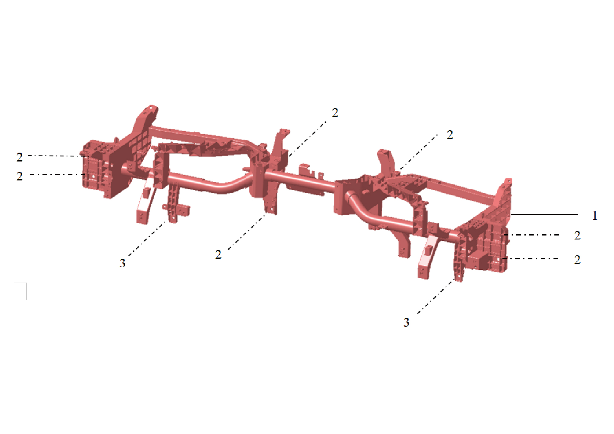
1.
3.
Hexagon Flange Bolt
Cross Car Beam Assy
2.
Hexagon Flange Bolt
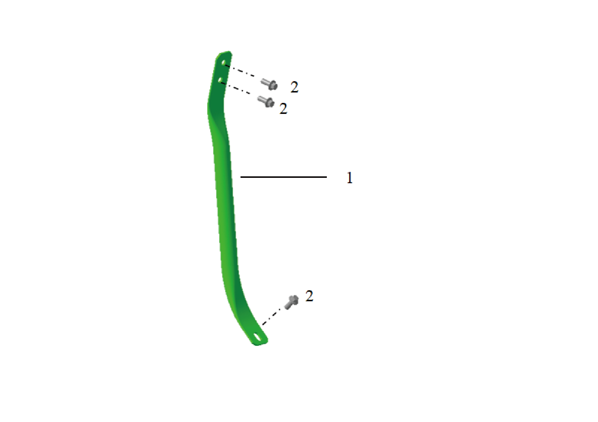
1.
2.
Hexagon Flange Bolt
Cross Car Beam Pole
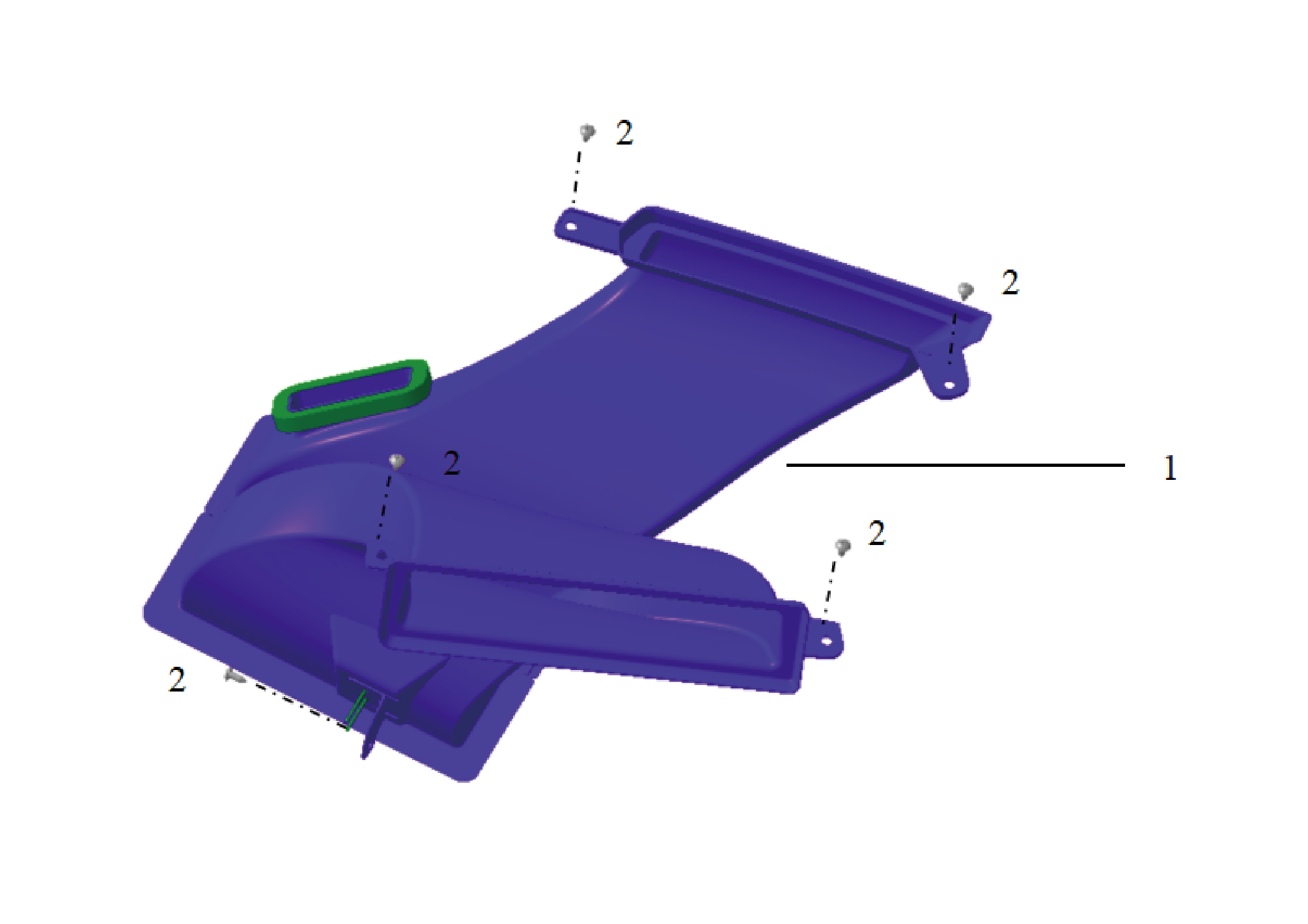
1.
2.
Front Defrost Air Outlet Assy-Lh
Self-Tapping Screw
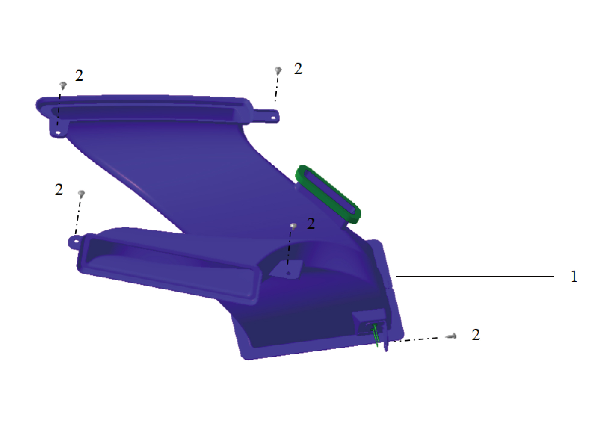
1.
2.
Front Defrost Vent Assy-Rh
Self-Tapping Screw
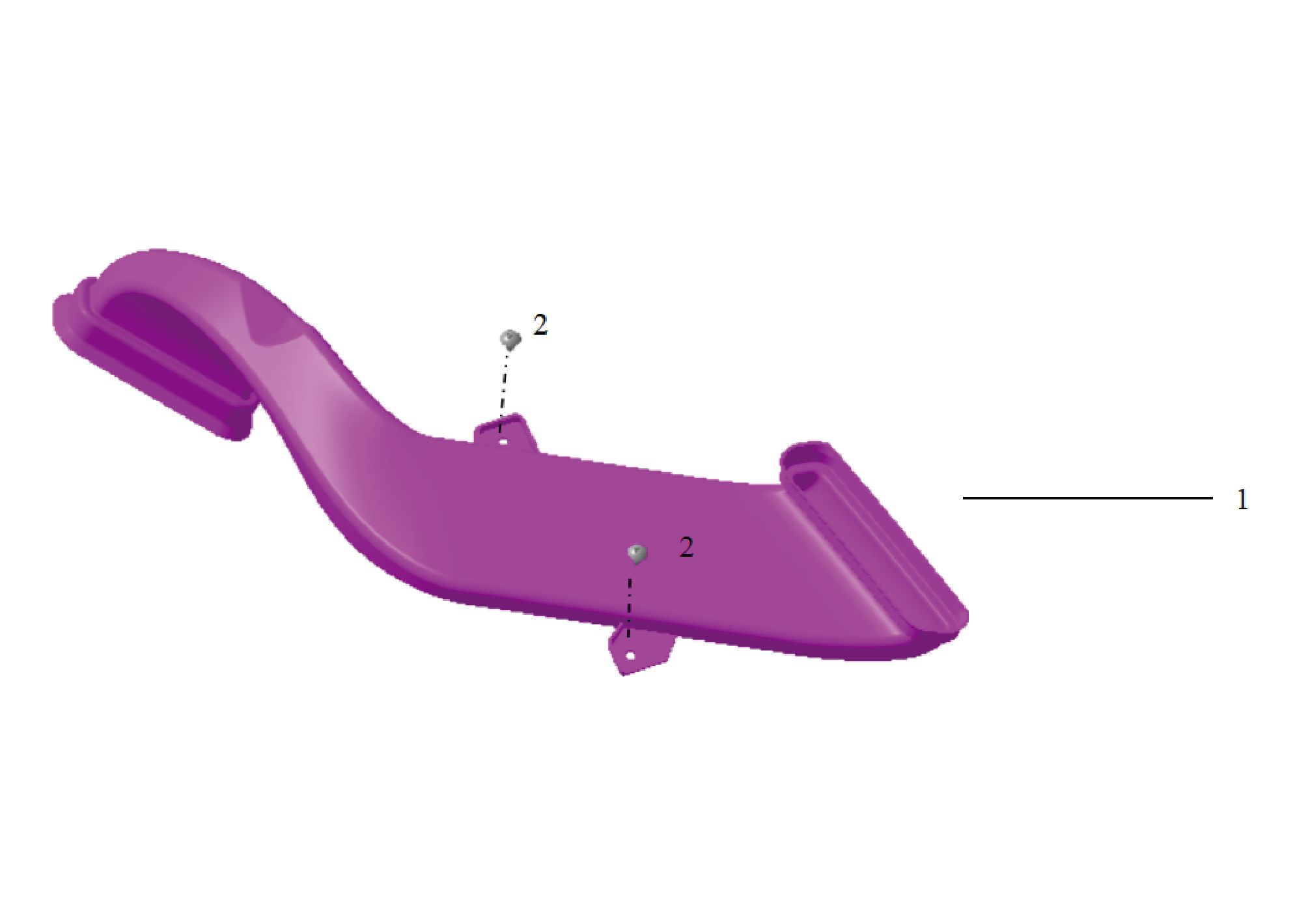
1.
2.
Duct Assy-Defrost Rh
Self-Tapping Screw
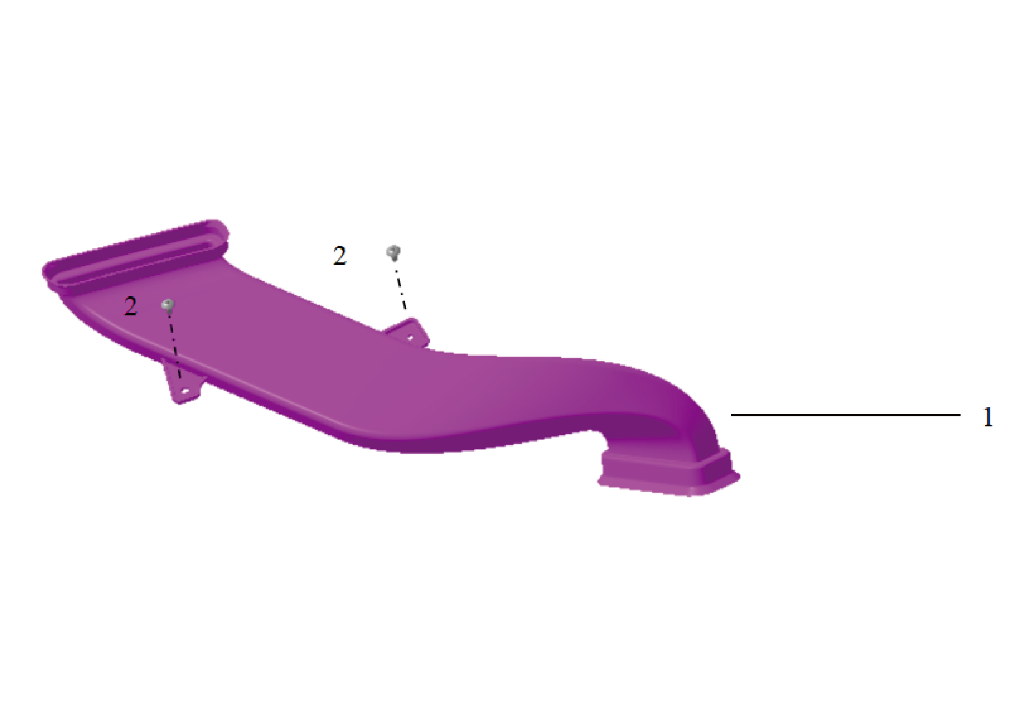
1.
2.
Defrost Duct Assy-Lh
Self-Tapping Screw
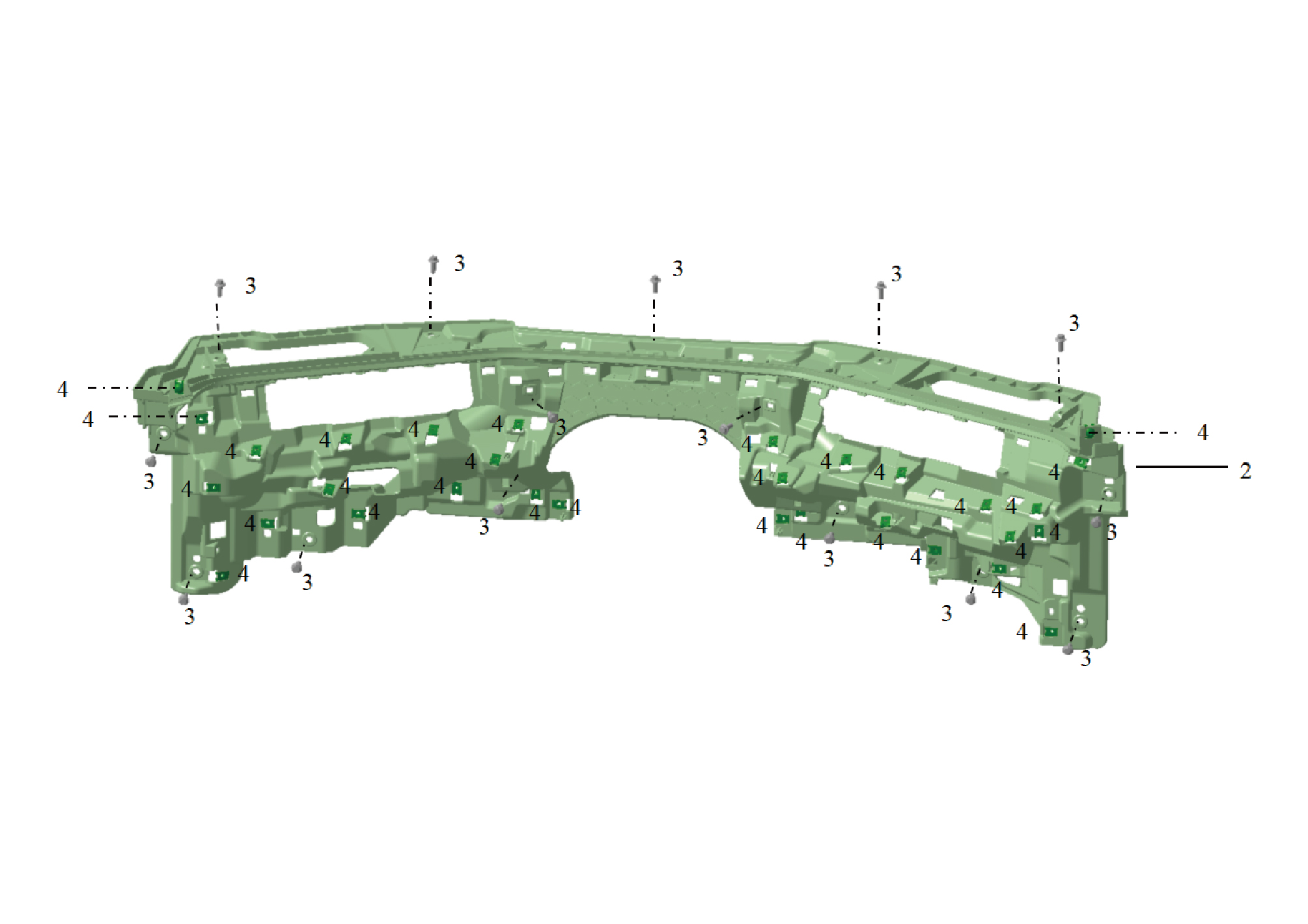
2.
4.
Reed Nut
Lower Body of the Instrument Panel
3.
Hexagon Flange Bolt
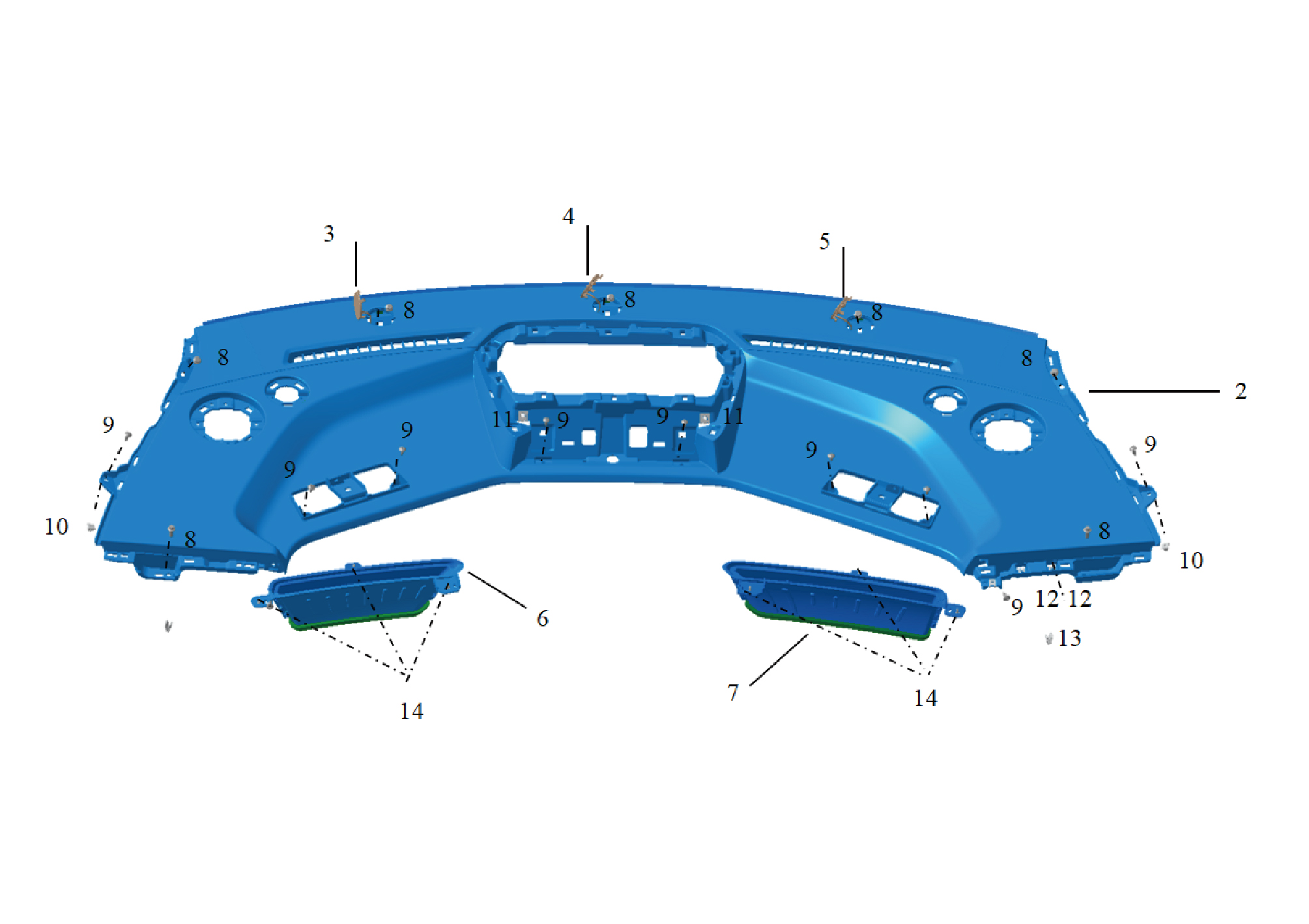
2.
9.
Upper Body of the Instrument Panel
Self-Tapping Screw
3.
10.
Plastic Nut
Screw Cover on the Left Side of the Instrument Panel
4.
11.
Reed Nut
Screw Cover in the Middle of the Instrument Panel
5.
12.
Reed Nut
Screw Cover on the Right Side of the Instrument Panel
6.
13.
Plastic Buckle
Defrost Air Outlet Assembly on the Left Side of the
Instrument Panel
7.
14.
Defrost air outlet assembly on the right side of the
Self-Tapping Screw
instrument panel
8.
Hexagon Flange Bolt
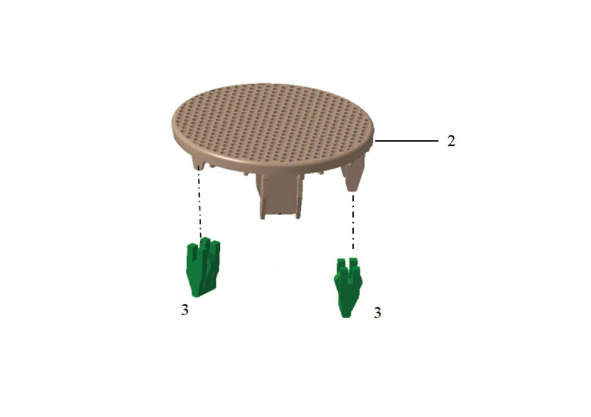
2.
3.
Reed Buckle
Tweeter Speaker Grille of the Instrument Panel
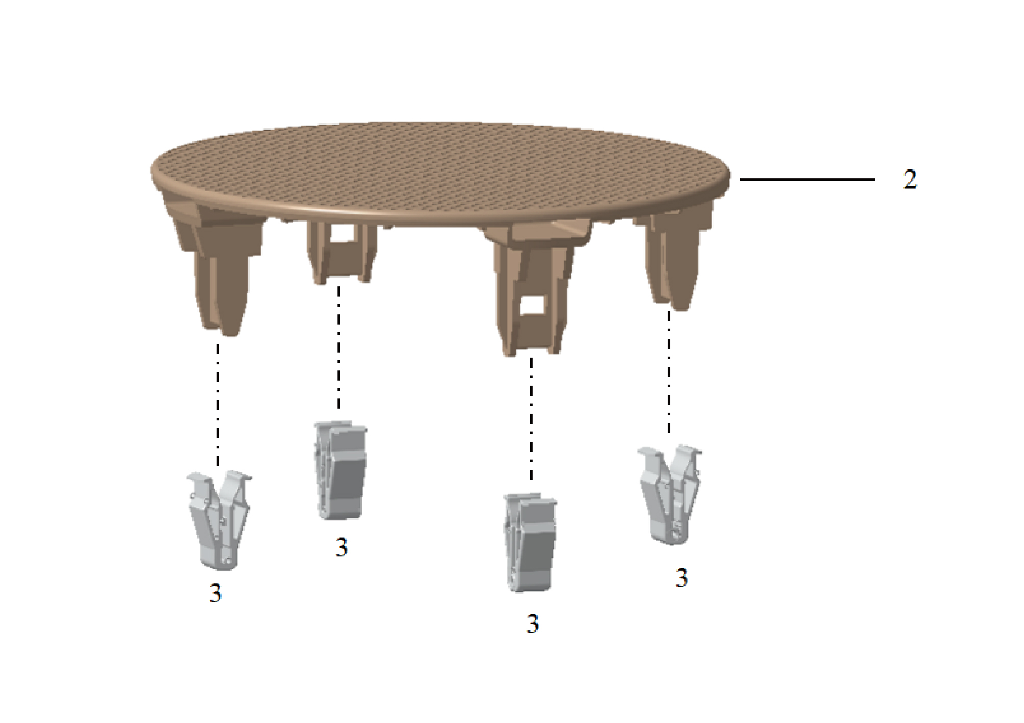
2.
3.
Plastic Buckle
Midrange Speaker Grille of the Instrument Panel
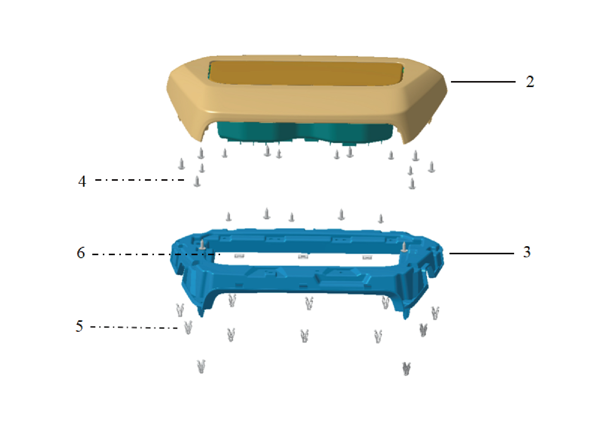
5.
2.
Plastic Buckle
Visor Outer Panel Assembly of the Instrument Panel
3.
6.
Metal Buckle
Visor Inner Panel of the Instrument Panel
4.
Self-Tapping Screw
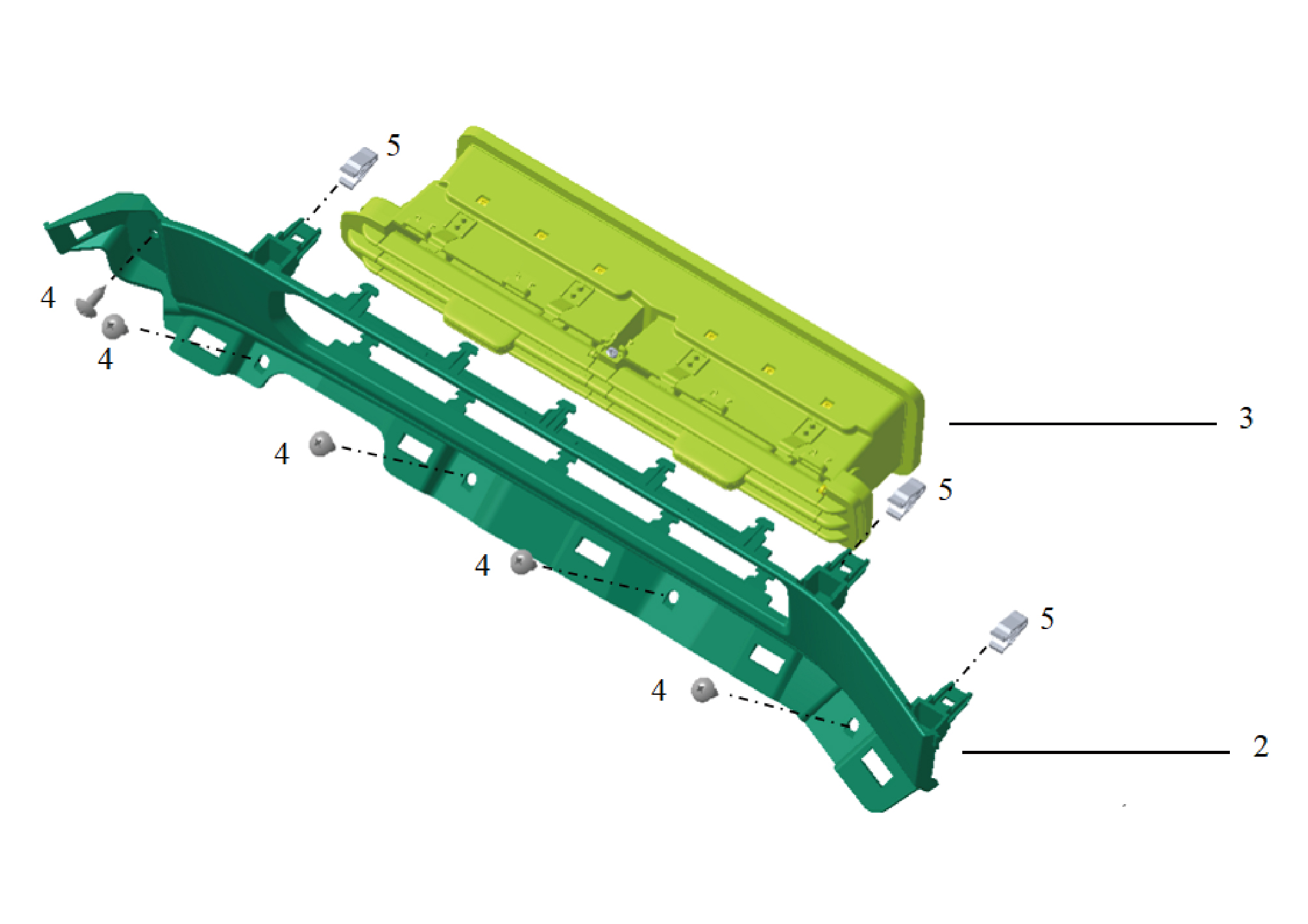
2.
4.
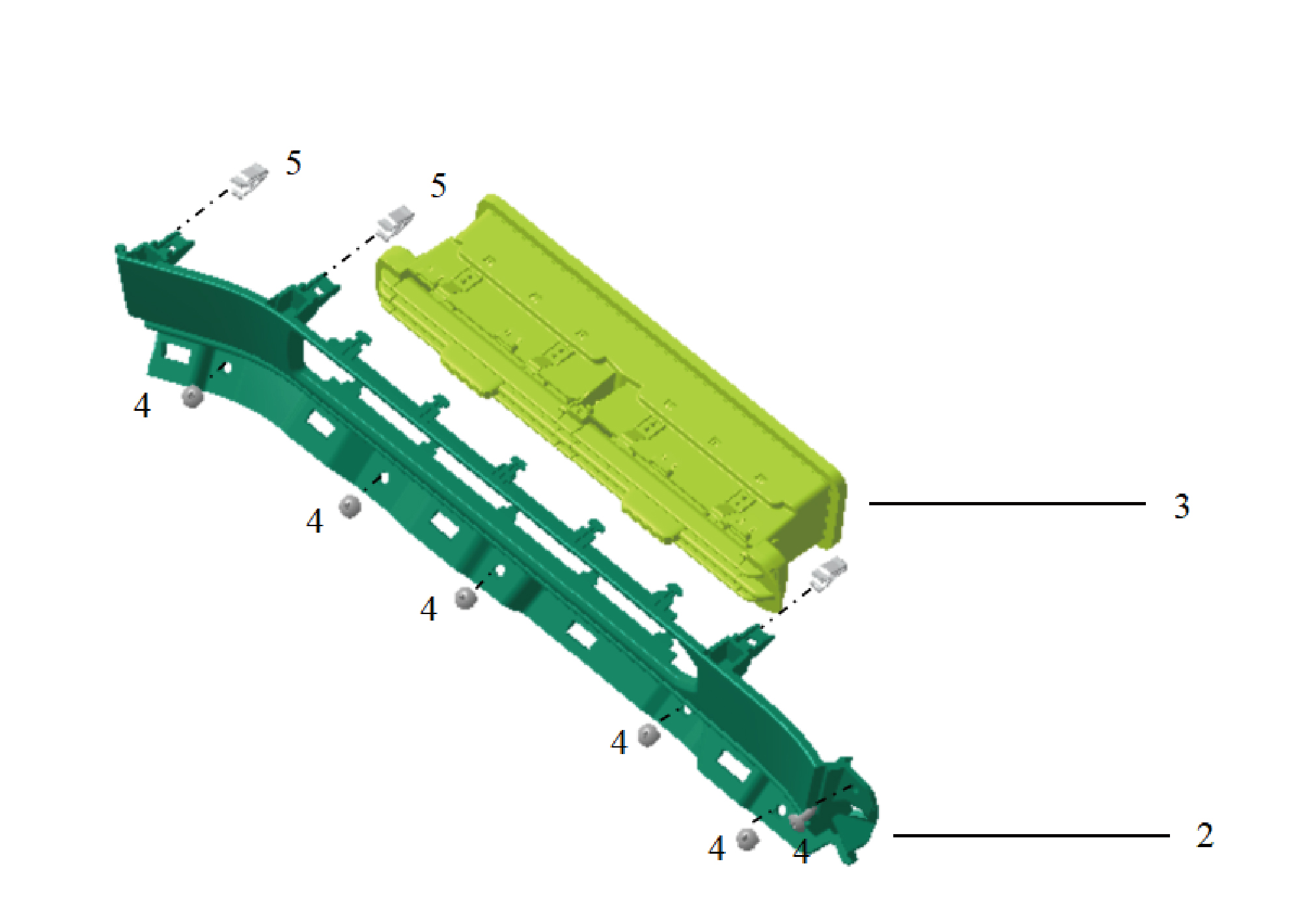
Decorative Panel of the Left Air Outlet
Self-Tapping Screw
5.
3.
Plastic Buckle
Left Air Outlet Assembly
2.
4.
Decorative Panel of the Right Air Outlet
Self-Tapping Screw
5.
3.
Plastic Buckle
Right Air Outlet Assembly
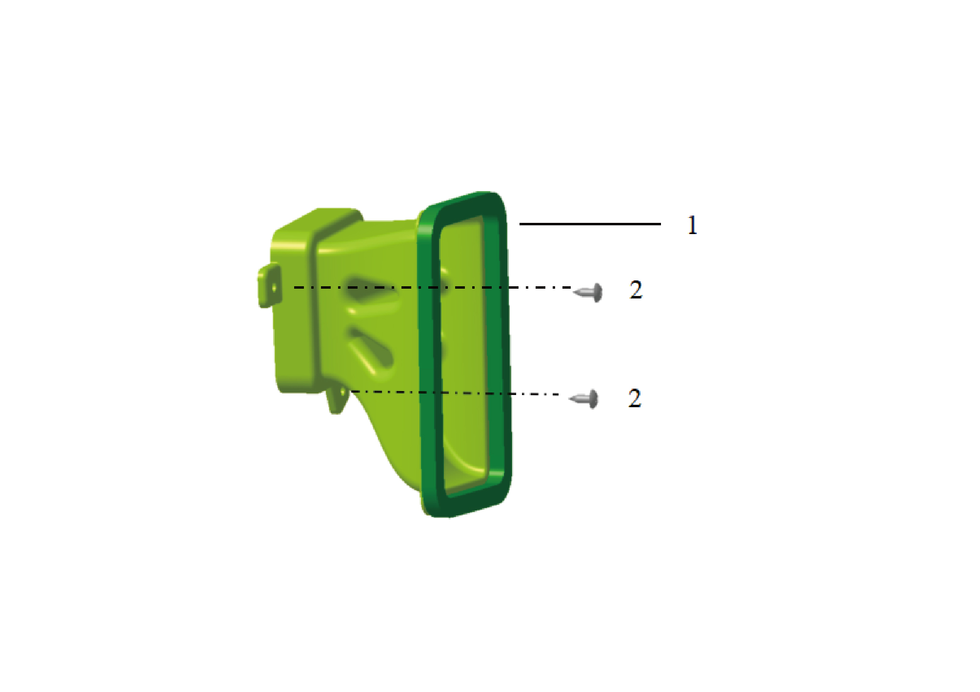
1.
2.
Side Blowing Air Duct Assy-Lh
Self-Tapping Screw
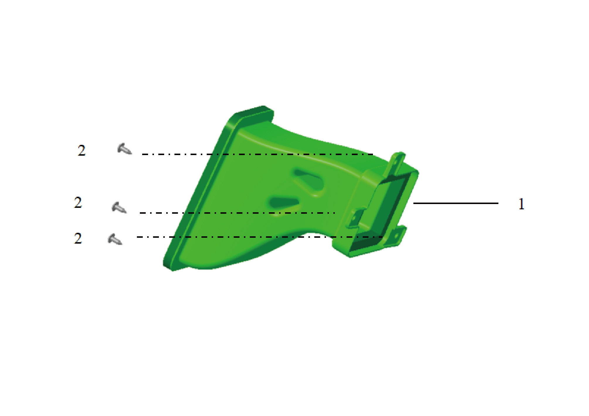
1.
Blowing Air Duct Assy-Rh
2.
Self-Tapping Screw
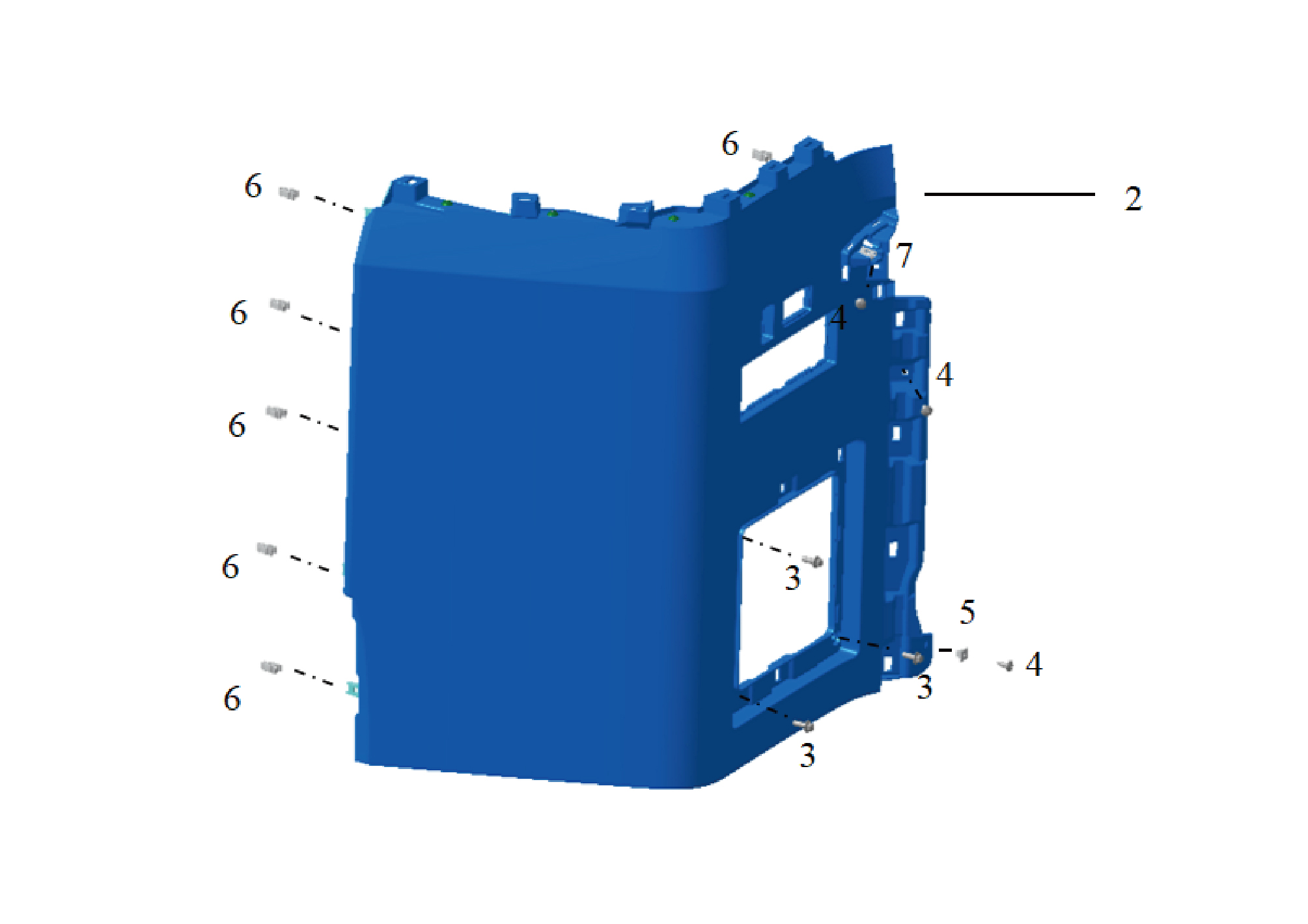
5.
2.
Plastic Nut
Welded Assembly of the Left Lower Trim Panel of the
Instrument Panel
3.
Hexagon Flange Bolt
6.
Plastic Buckle
7.
4.
Reed Nut
Self-Tapping Screw
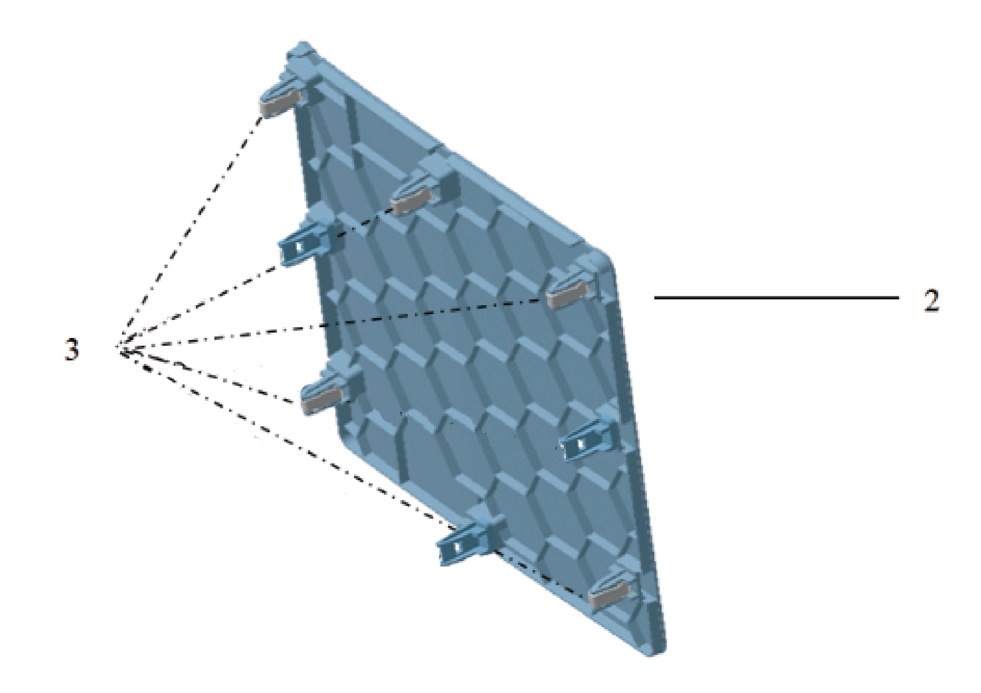
2.
3.
Plastic Buckle
Left Access Panel Cover
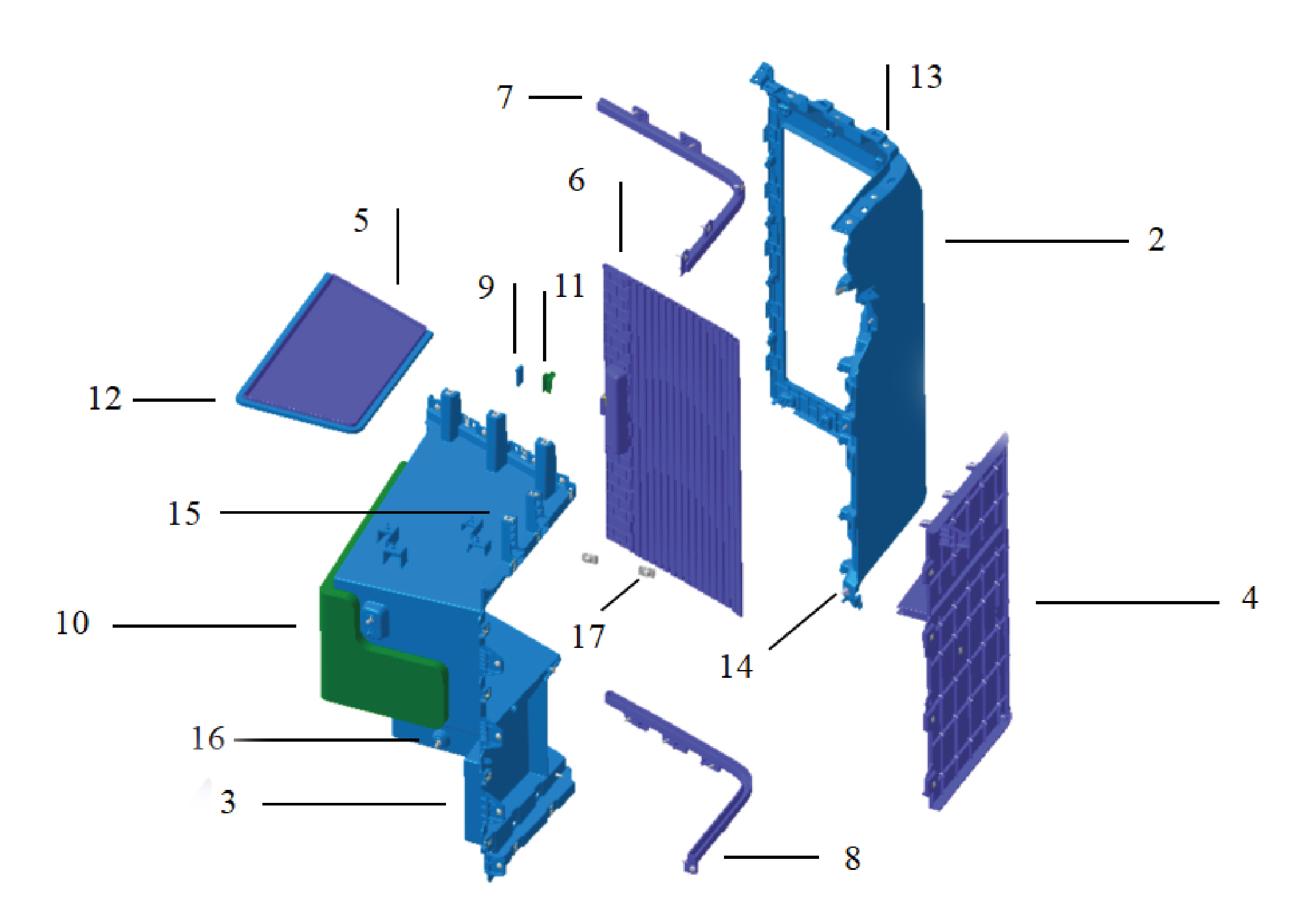
2.
10.
Outer Panel of the Storage Box
Sound-Absorbing Cotton of the Storage Box
3.
11.
Body of the Storage Box
Felt of the Storage Box
4.
12.
Side Panel of the Storage Box
Rubber Strip of the Storage Box
5.
13.
Shelf of the Storage Box
Self-Tapping Screw
6.
14.
Plastic Nut
Roller Blind of the Storage Box
7.
15.
Reed Nut
Upper Guide Rail of the Storage Box
8.
16.
Plastic Buckle
Lower Guide Rail of the Storage Box
9.
17.
Reed Nut
Magnet of the Storage Box
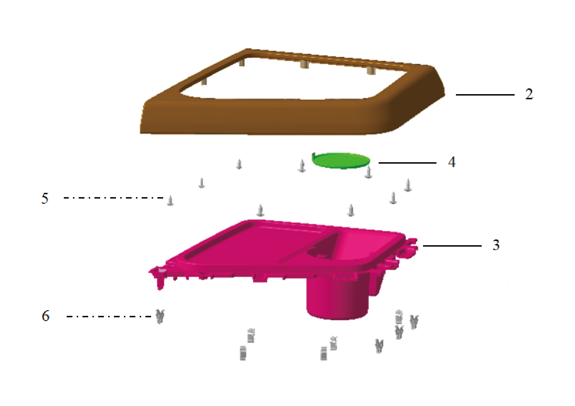
5.
2.
Covered Assembly of the Upper Left Trim Panel of the
Self-Tapping Screw
Instrument Panel
3.
6.
Plastic Buckle
Cup Holder Trim Panel on the Left Side of the
Instrument Panel
4.
Cup Holder Mat
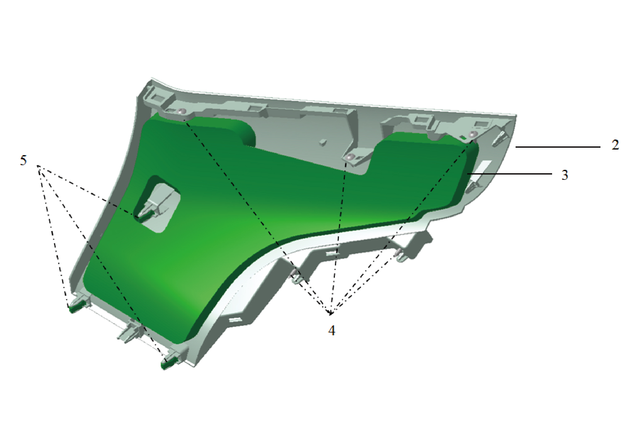
2.
4.
Upper Right Trim Panel of the Instrument Panel
Self-Tapping Screw
5.
3.
Plastic Buckle
Sound-Absorbing Cotton of the Upper Right Trim Panel
of the Instrument Panel
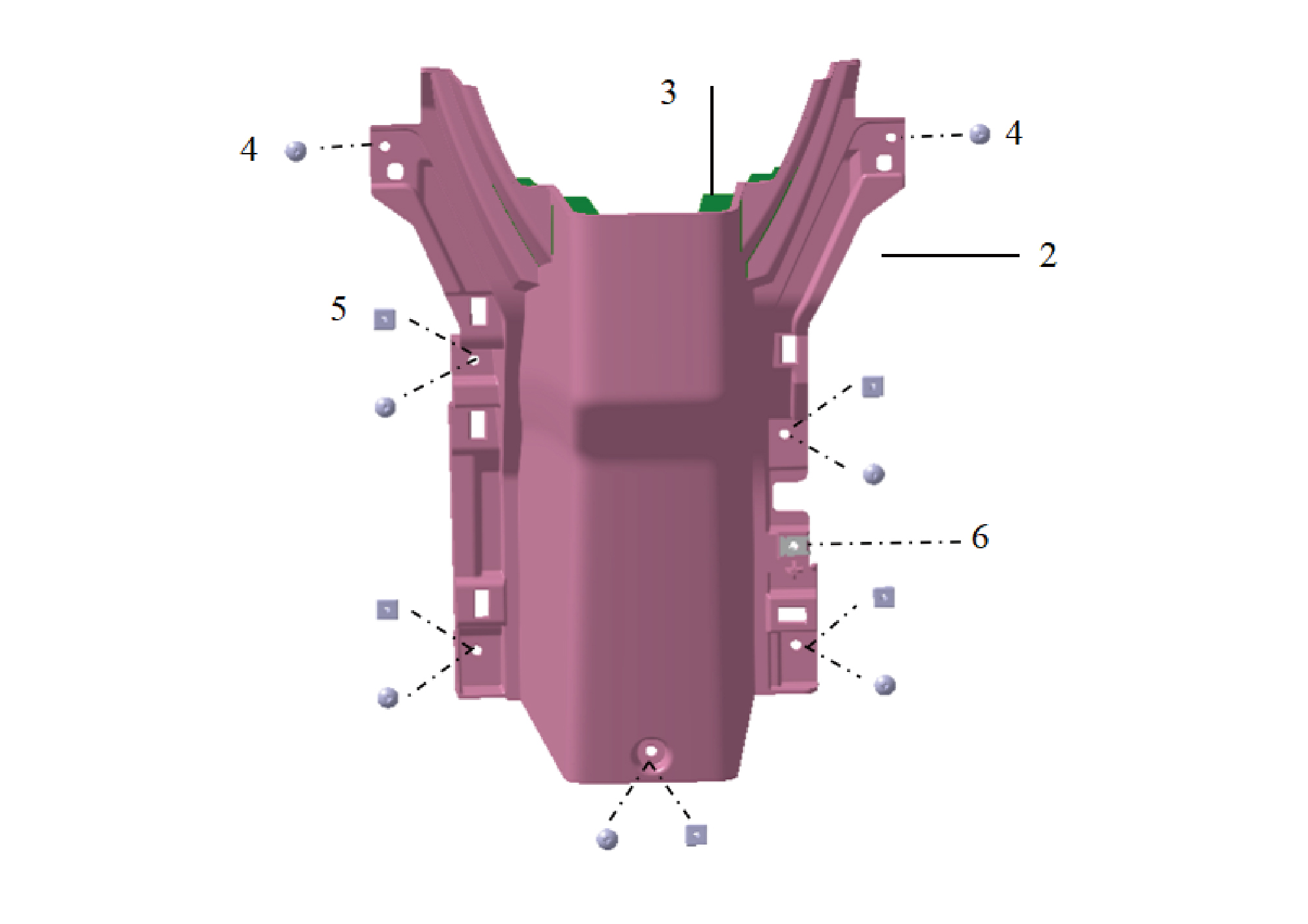
5.
2.
Plastic Nut
Lower Shroud of the Steering Column
3.
6.
Reed Nut
Sound-Absorbing Cotton of the Lower Shroud of the
Steering Column
4.
Self-Tapping Screw
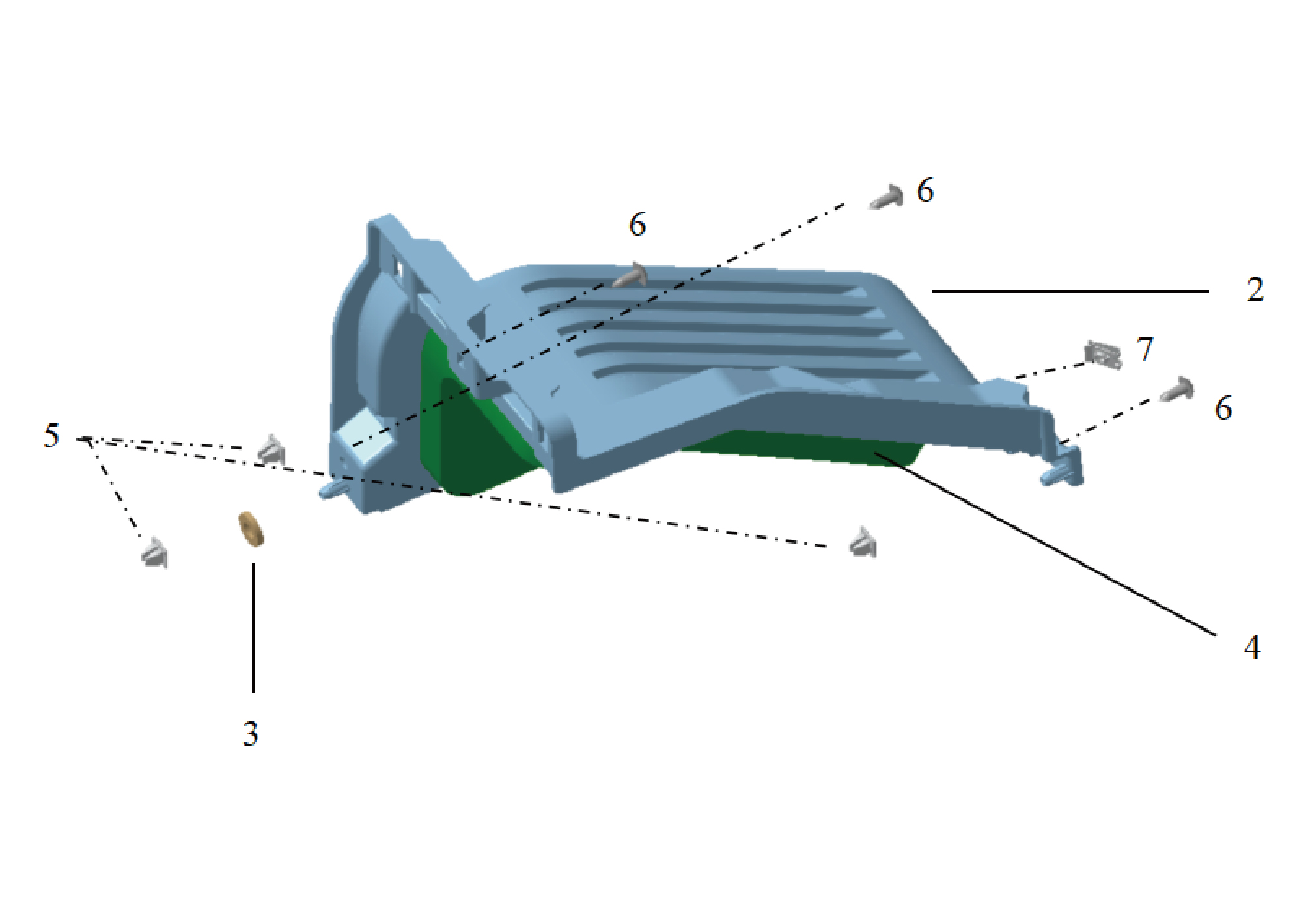
5.
2.
Dead Pedal
Plastic Nut
3.
6.
Felt of the Dead Pedal
Self-Tapping Screw
7.
4.
Reed Nut
Sponge of the Dead Pedal
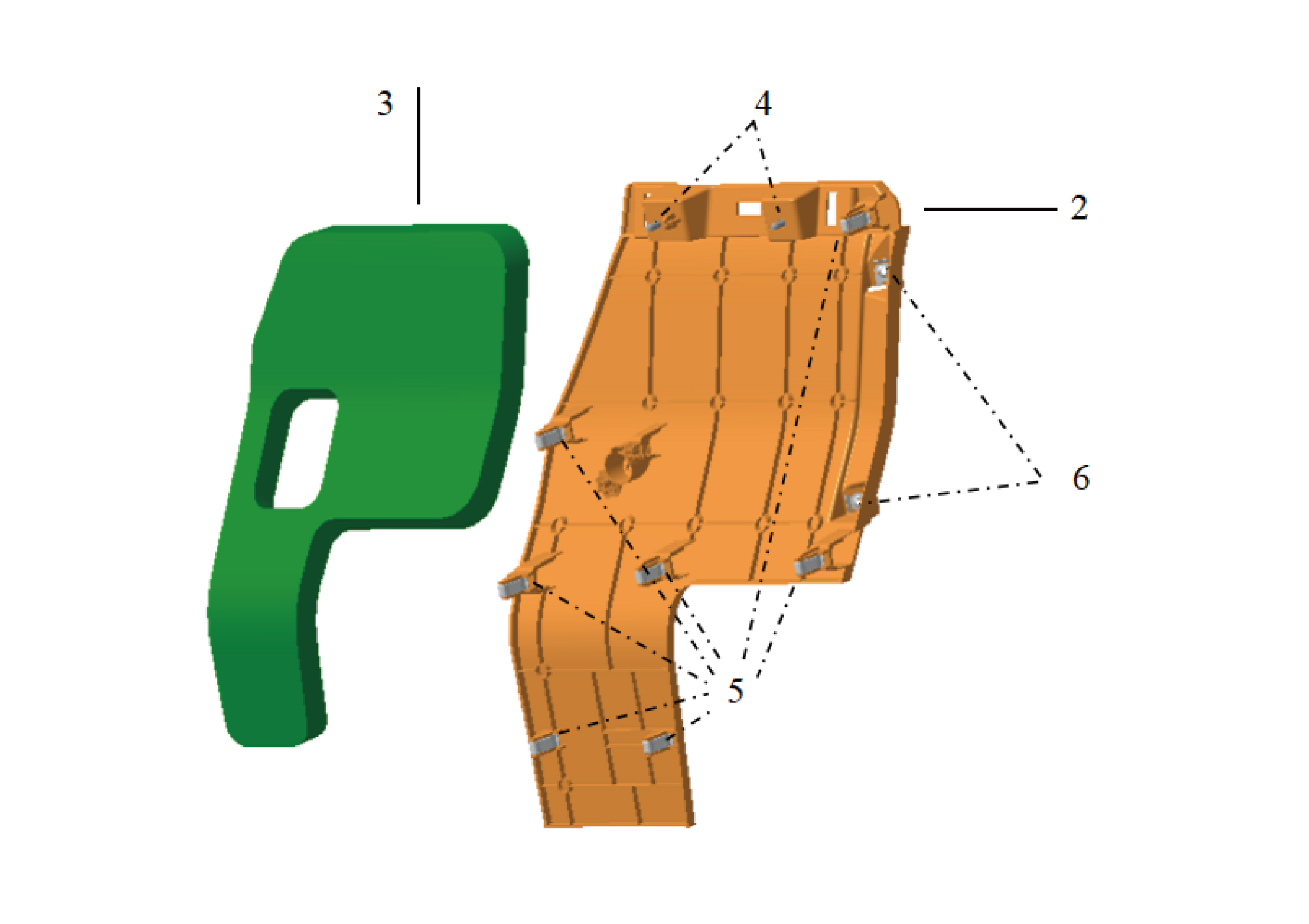
5.
2.
Plastic Buckle
Front Left Trim Panel of the Instrument Panel
3.
6.
Reed Nut
Sound-Absorbing Cotton of the Front Left Trim Panel of
the Instrument Panel
4.
Self-Tapping Screw
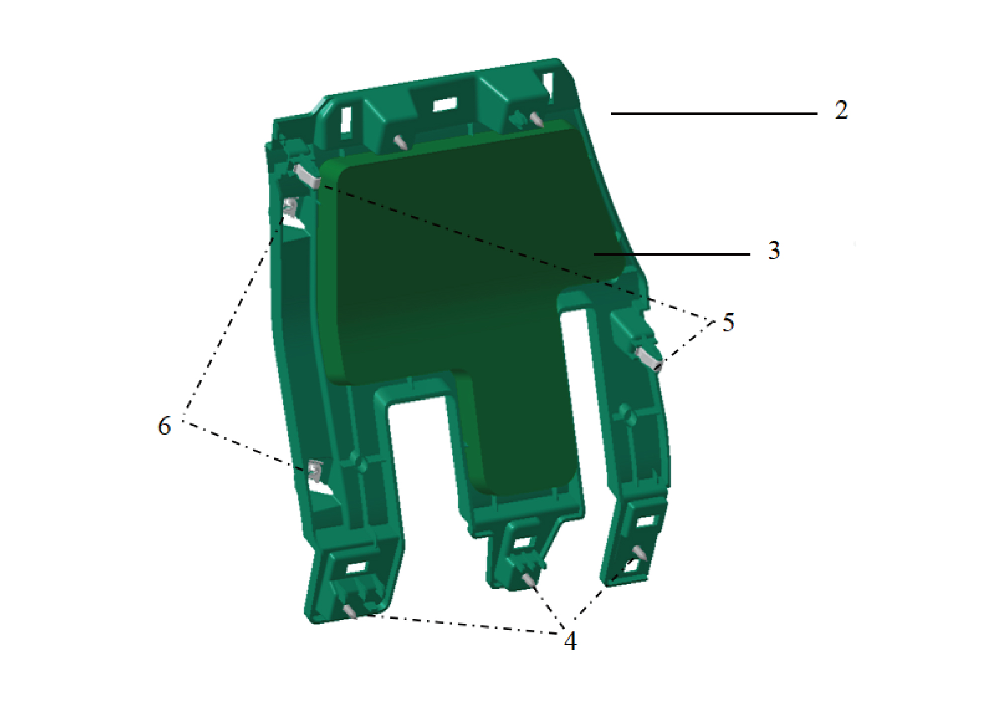
5.
2.
Plastic Buckle
Front Upper Right Trim panel of the Instrument Panel
3.
6.
Reed Nut
Sound-Absorbing Cotton of the Front Upper Right Trim
Panel of the Instrument Panel
4.
Self-Tapping Screw
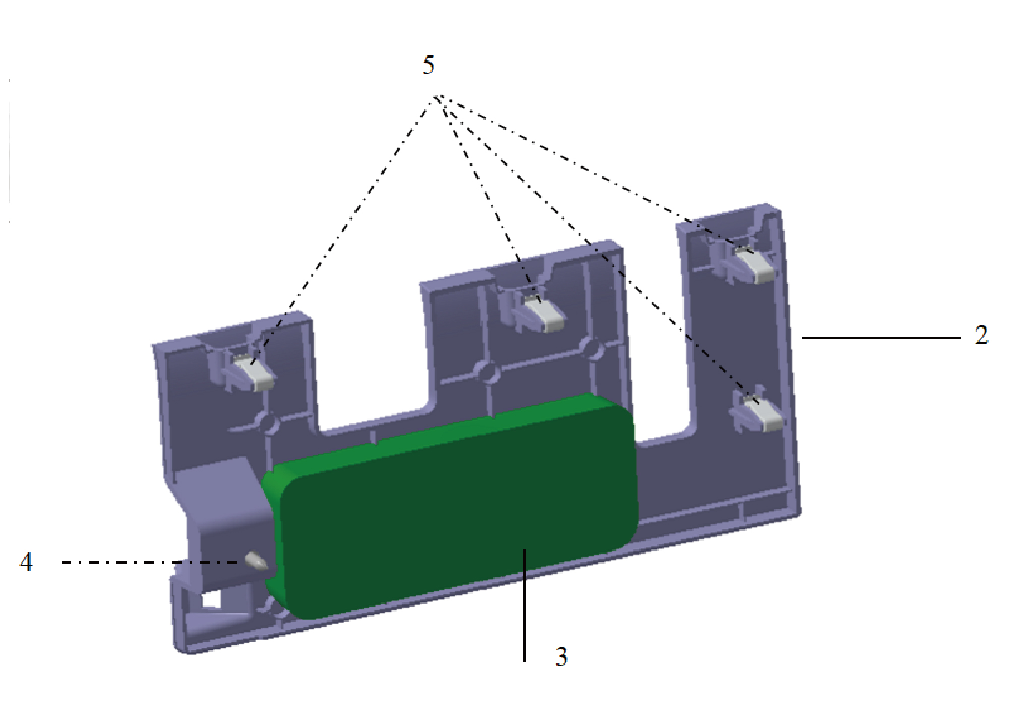
2.
4.
Front Lower Right Trim Panel of the Instrument Panel
Self-Tapping Screw
5.
3.
Plastic Buckle
Sound-Absorbing Cotton of the Front Lower Right Trim
Panel of the Instrument Panel
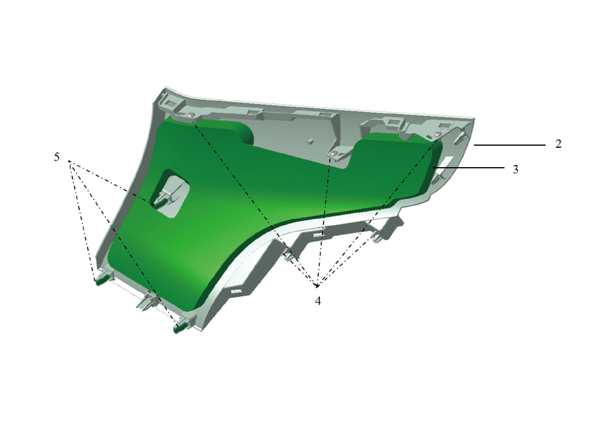
2.
4.
Upper Left Trim Panel of the Instrument Panel
Self-Tapping Screw
5.
3.
Plastic Buckle
Sound-Absorbing Cotton of the Upper Left Trim Panel
of the Instrument Panel
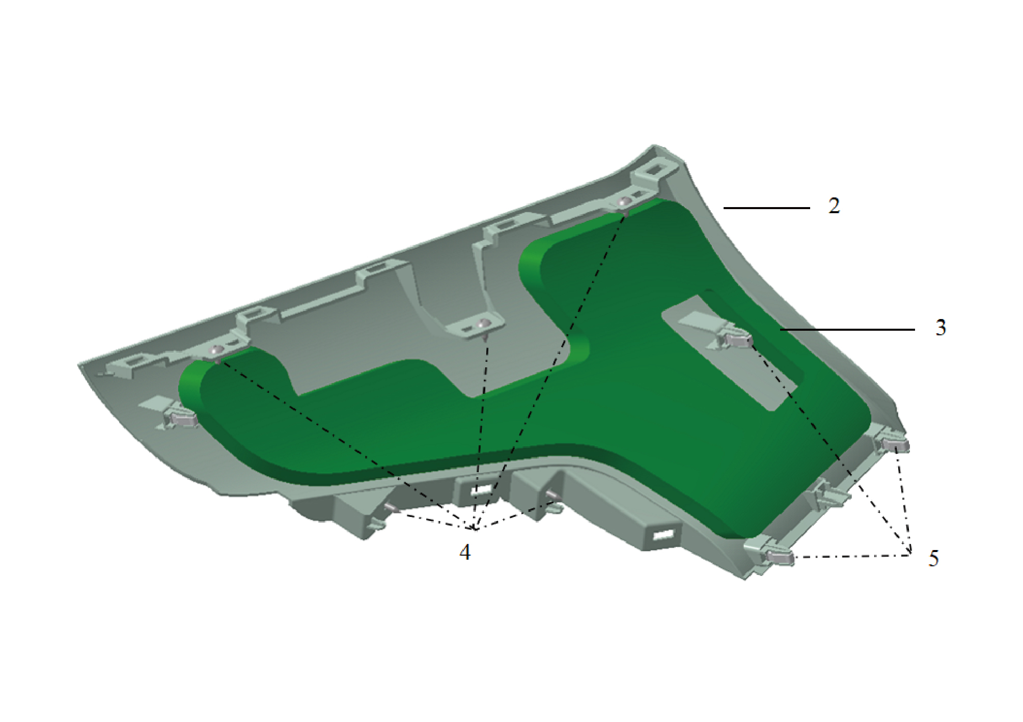
2.
4.
Lower Trim Panel of the Right Side Switch Panel
Self-Tapping Screw
5.
3.
Plastic Buckle
Sound-Absorbing Cotton of the Lower Trim Panel of the
Right Side Switch Panel
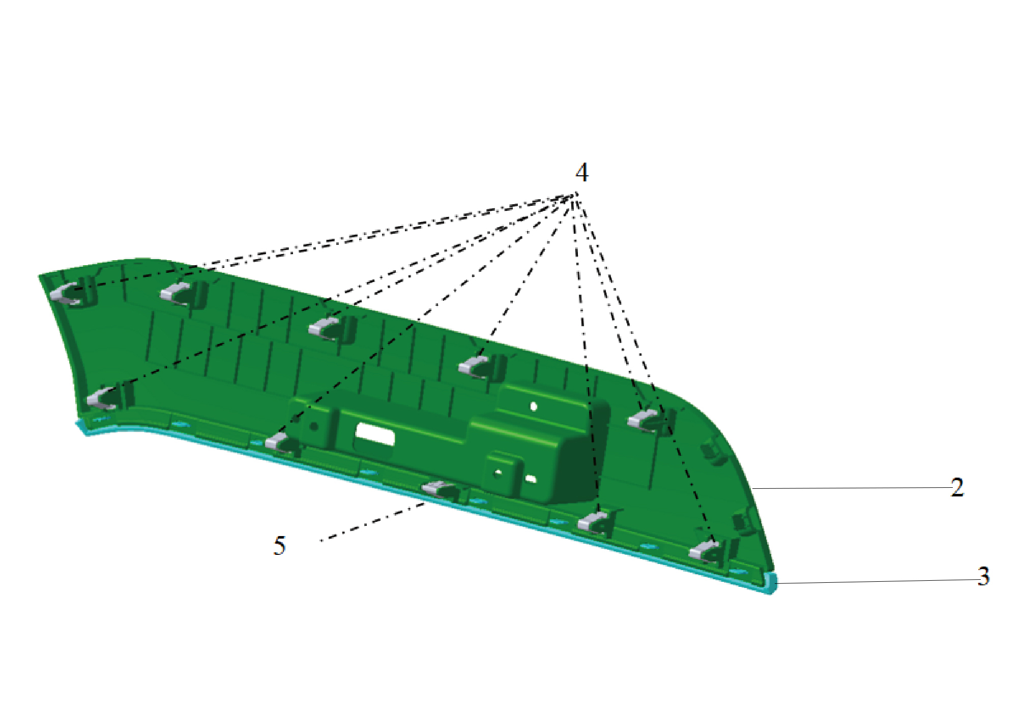
2.
4.
Plastic Buckle
Left Side Switch Panel
5.
3.
Metal Buckle
Bright Trim Strip of the Left Side Switch Panel
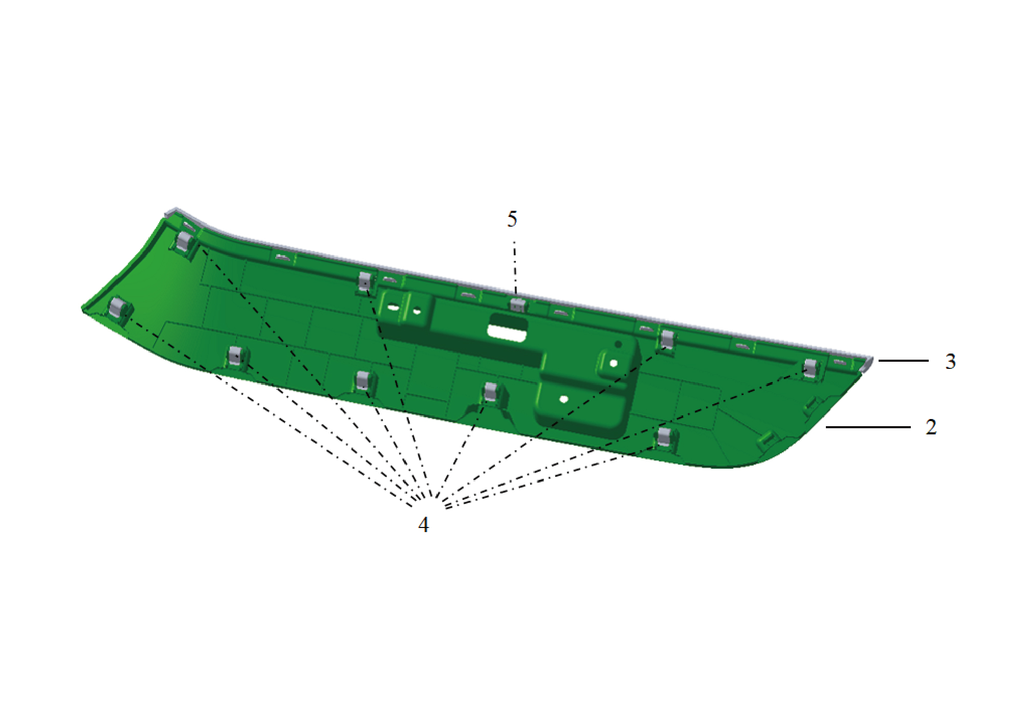
2.
4.
Plastic Buckle
Right Side Switch Panel
5.
3.
Metal Buckle
Bright Trim Strip of The Right Side Switch Panel
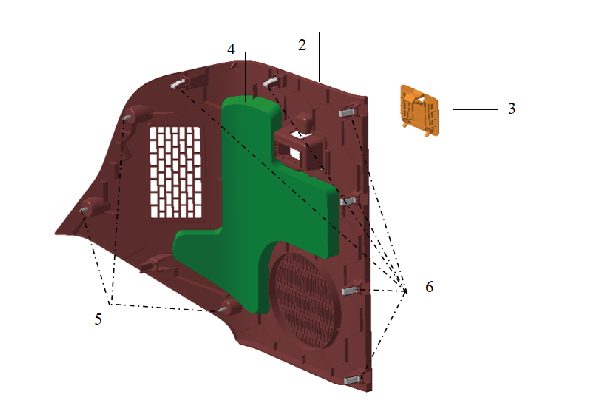
5.
2.
Maintenance Cover Plate on the Left Side of the
Self-Tapping Screw
Instrument Panel
3.
6.
Plastic Buckle
OBD Cover Plate
4.
Sound-Absorbing Cotton of the Maintenance Cover
Plate on the Left Side of the Instrument Panel
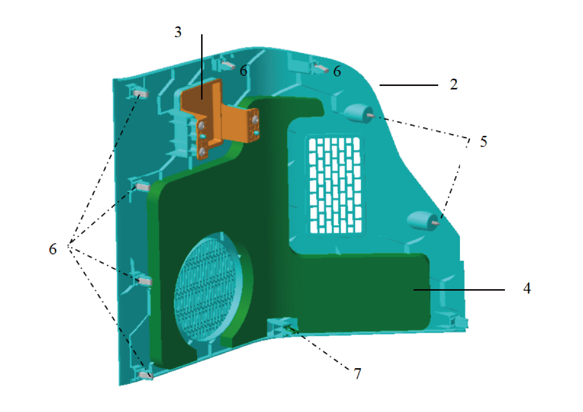
5.
2.
Maintenance Cover Plate on The Right Side of the
Self-Tapping Screw
Instrument Panel
3.
6.
Plastic Buckle
Fragrance Cover Plate
7.
4.
Metal Buckle
Sound-Absorbing Cotton of the Maintenance Cover
Plate on the Right Side of the Instrument Panel

1.
2.
Bracket-Under the Combination Switch
Cross Recessed Pan Head Machine Screw
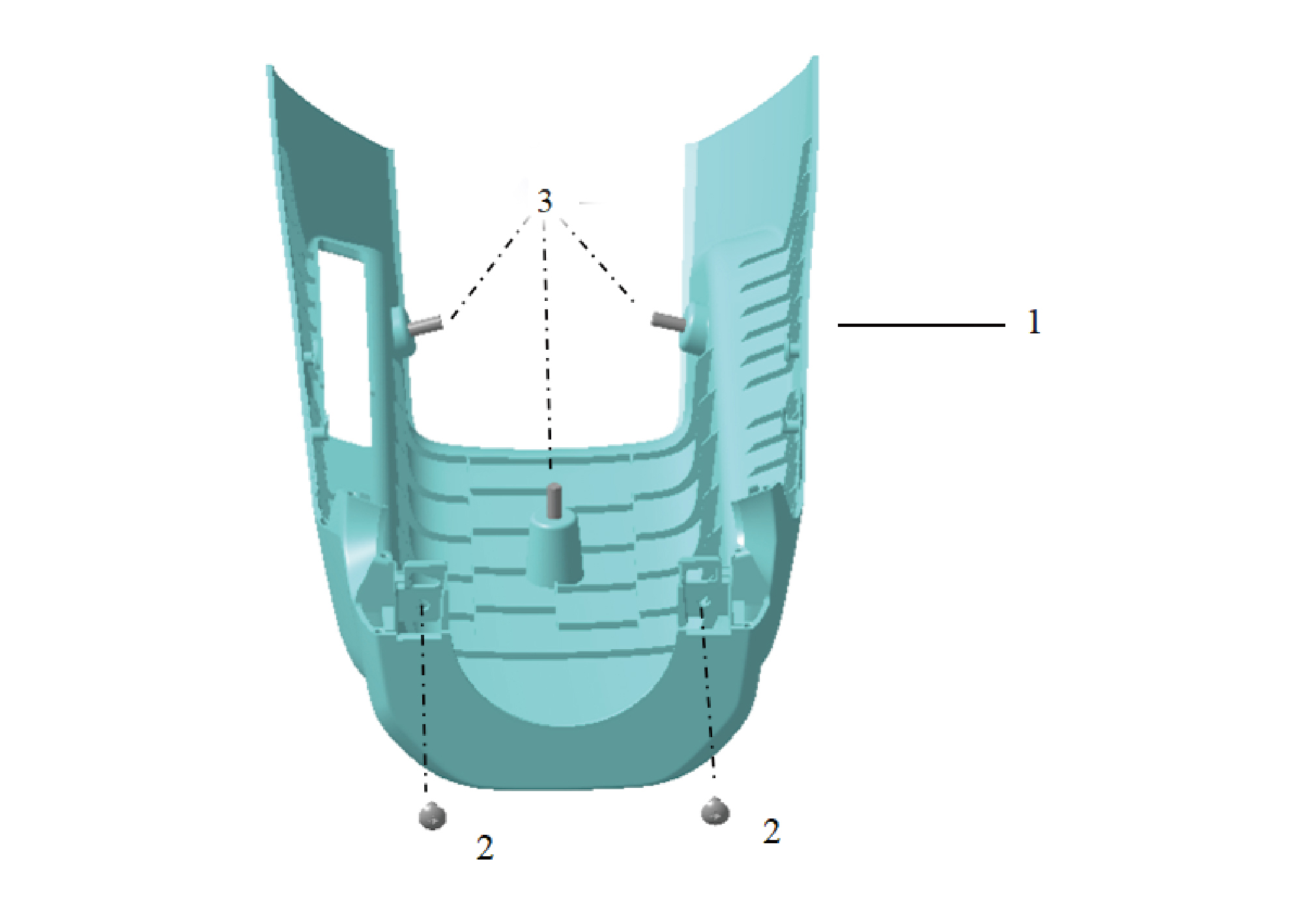
1.
3.
Cover-Combination Switch-Lor
Cross Recessed Pan Head Machine Screw
2.
Self-Tapping Screw
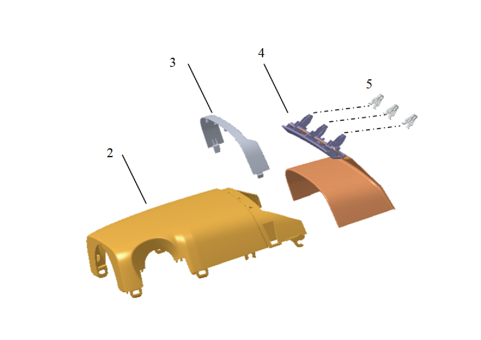
2.
4.
Upper Protective Cover of the Combination Switch
Assembly of the Pressing Strip Under the Protective
Cover Flap
5.
3.
Plastic Buckle
Pressing Strip Under the Protective Cover Flap
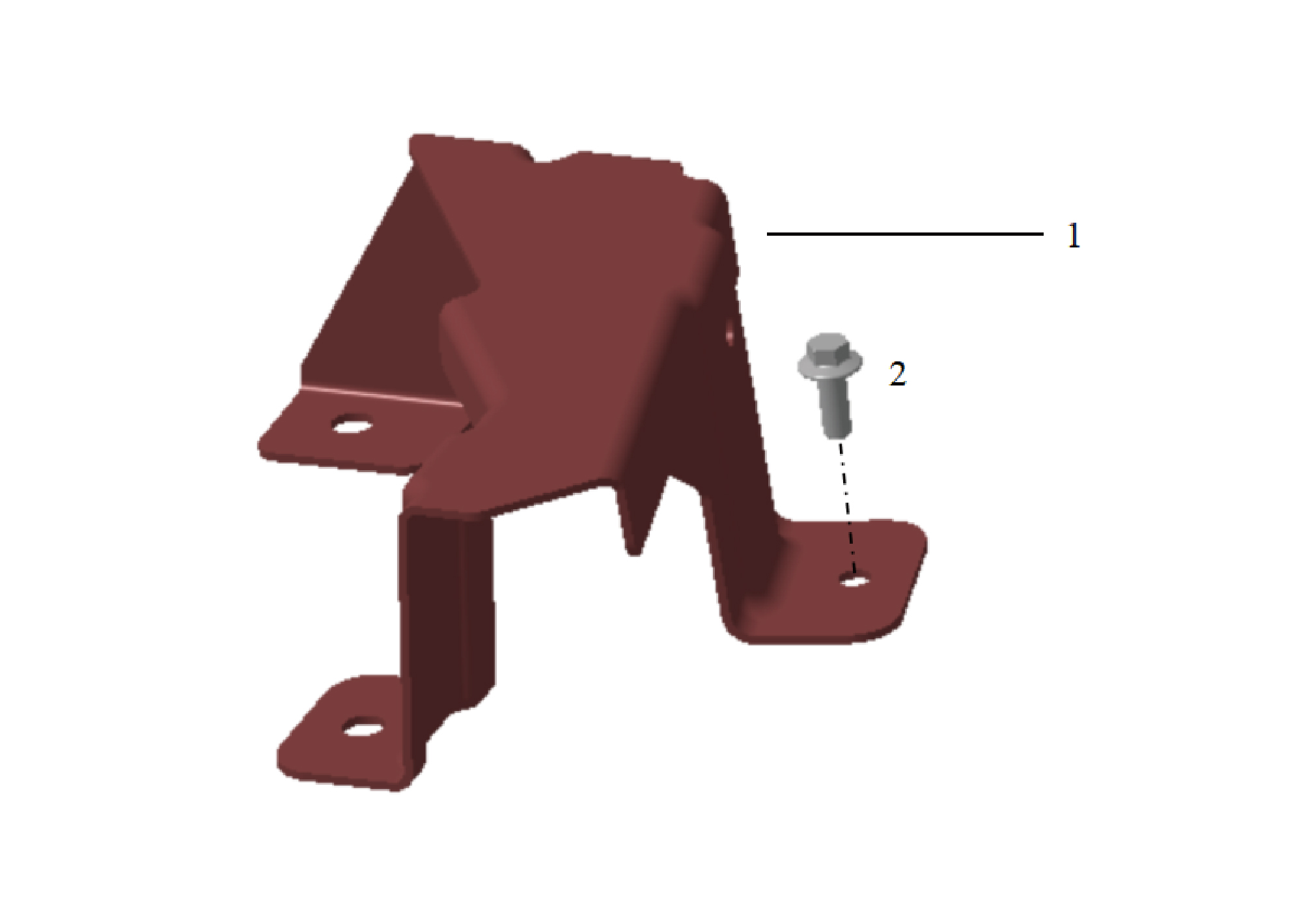
1.
2.
Hexagon Flange Bolt
Storage Box Bracket Assy
6.11.3 Dismantling and Installation
6.11.3.1 Replacement of Tubular Beam Assembly
Assembly
Removal Procedures
1
Open the door.
2
Open the front flip cover plate.
3
Disconnect the battery negative cable.
caution
power down the high-voltage system before
disconnecting the negative pole of the storage
battery.
4
Remove the wiper arm assy.
5
Remove the assembly of the front windshield cover.
6
Remove the dab decorative cove.
7
Remove the steering wheel assy.
8
Remove the cover-combination switch-lor.
9
Remove the ip brim assy.
10
Remove the IVI screen.
11
Remove the CAR screen.
12
Remove the IPC screen.
13
Remove the upr cover- lh camera brkt.
14
Remove the camera monitor screen.
15
Remove the base-lh display brkt.
16
Remove the upr cover- rh camera brkt.
17
Remove the camera monitor screen-rh.
18
Remove the base-rh display brkt.
19
Remove the a-pillar guard assy-lh.
20
Remove the a-pillar guard assy-rh.
21
Remove the assembly of the instrument panel trim panel
assy-lowerr lh.
22
Remove the front side enclosure assy-lh.
23
Remove the cover assy-dashboard-lh frt.
24
Remove the trim assy on the switch panel-lh.
25
Remove the switch panel lower trim assy-lh.
26
Remove the vehicle travelling data recorder.
27
Remove the instrument panel trim panel assy- upper lh.
28
Remove the air vent decorative plate assy-lh.
29
Remove the assembly of the cover assy-steering under
column guard.
30
Remove the front side enclosure assy-rh.
31
Remove the cover assy-dashboard-rh frt.
32
Remove the switch panel assy-rh.
33
Remove the lower switch panel assy-rh.
34
Remove the storage box assy-rh.
35
Remove the air vent decorative plate assy-rh.
36
Remove the ontology assy on the dashboard.
37
Remove the trim assy-dashboard-lh frt.
38
Remove the lor trim assy-dashboard-rh frt.
39
Remove the decorative plate assy-dashboard-rh frt.
40
Remove the cover assy-defrost frt.
41
Remove the ontology assy under the dashboard.
42
Remove the AR-HUD.
43
Remove the fixing bracket-lh.
44
Remove the smart appliance box.
45
Remove the cockpit domain controller.
46
Remove the cockpit domain controller bracket.
47
Remove the Tbox-gw.
48
Remove the Tbox-gw bracket.
49
Remove the EBS controller assy.
50
Remove the EBS bracket.
51
Remove the body domain control unit.
52
Remove the controller bracket assy.
53
Remove the cross car beam pole.
54
Remove 2 fixing bolts connecting the combination
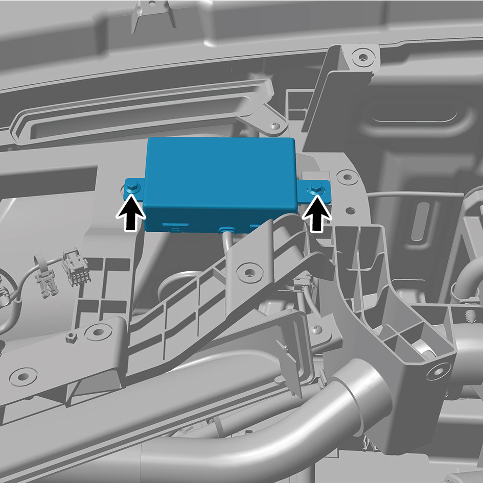
antenna to the tubular beam assembly, and move the
combination antenna to a safe and suitable location.
55
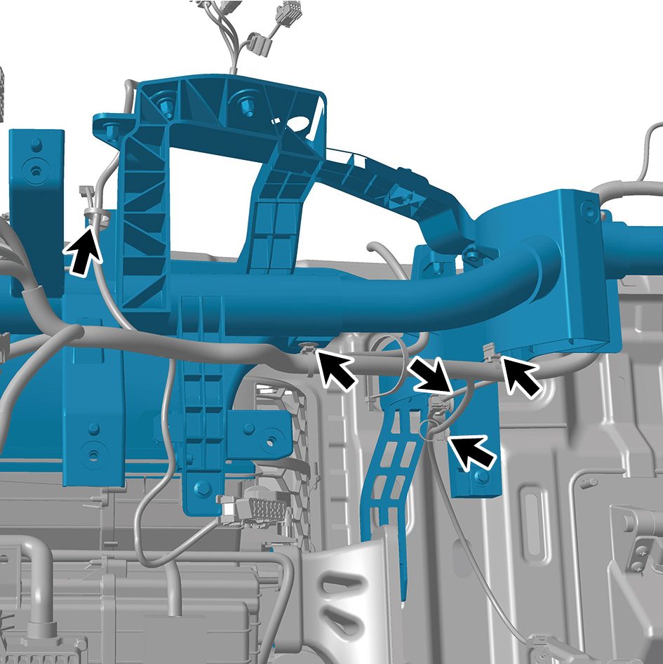
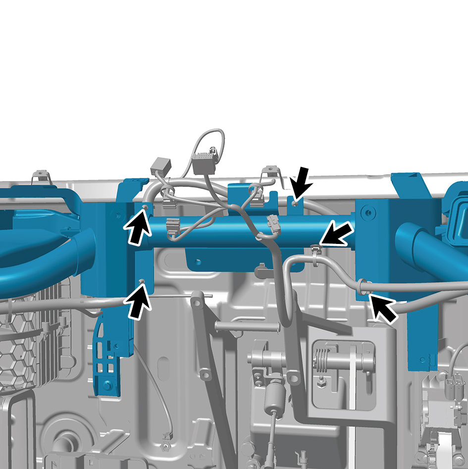
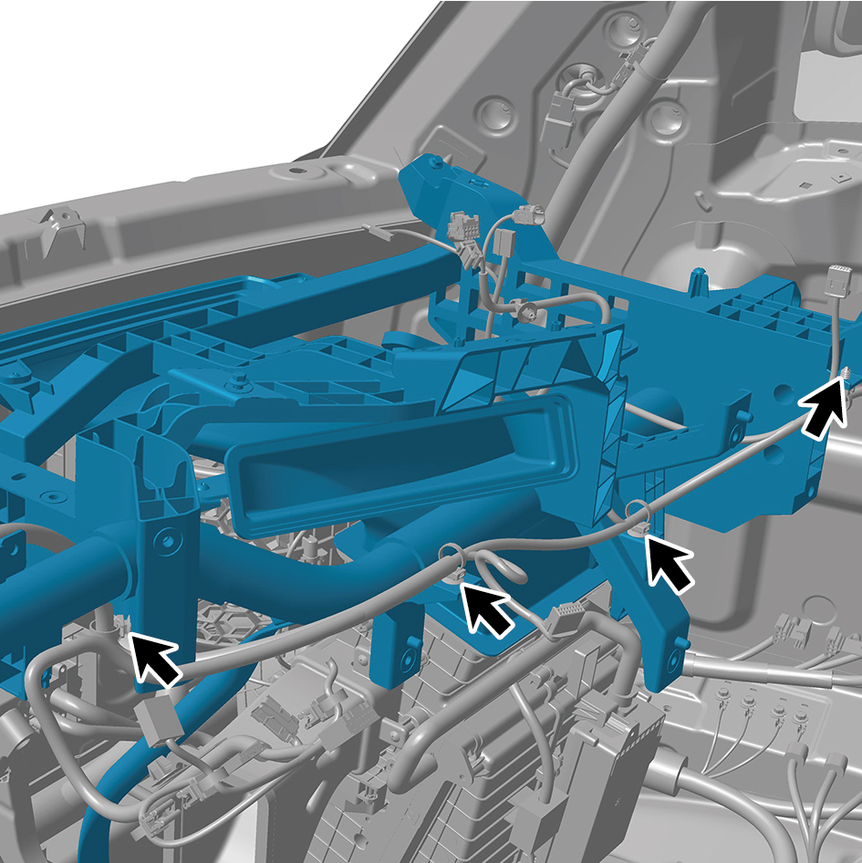
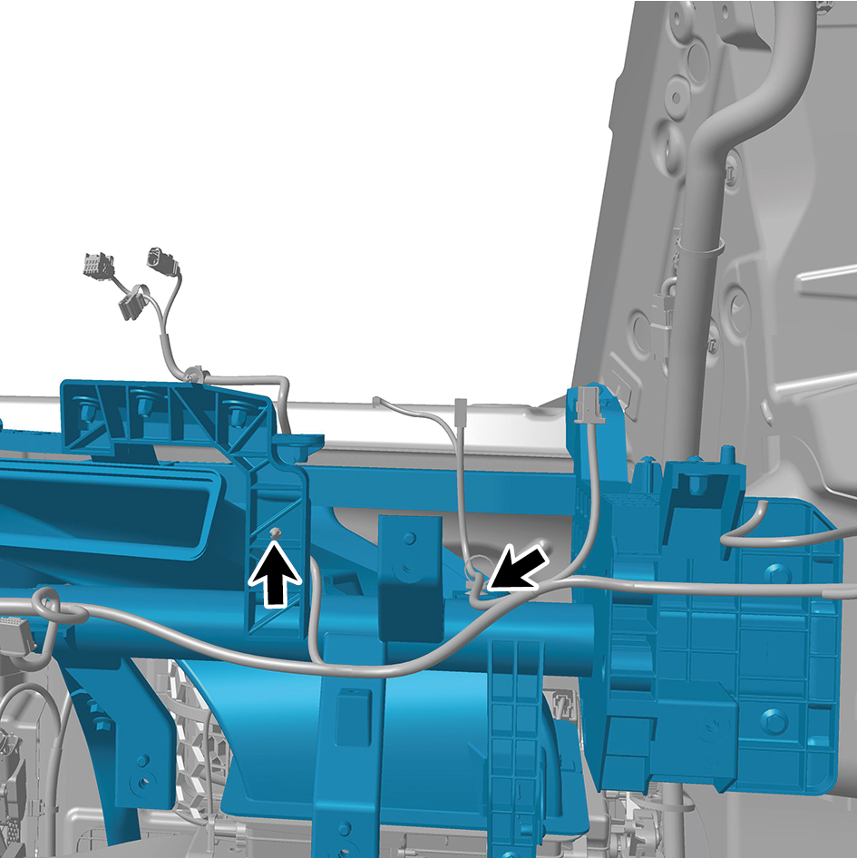
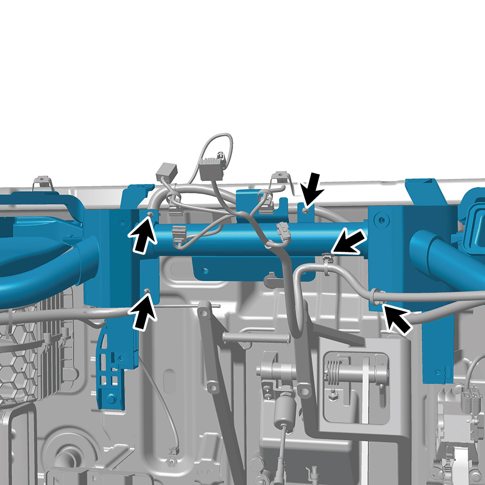
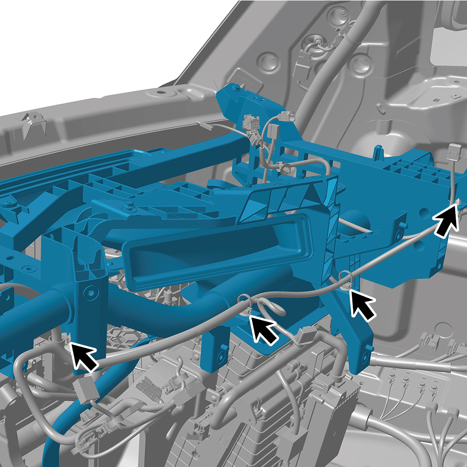
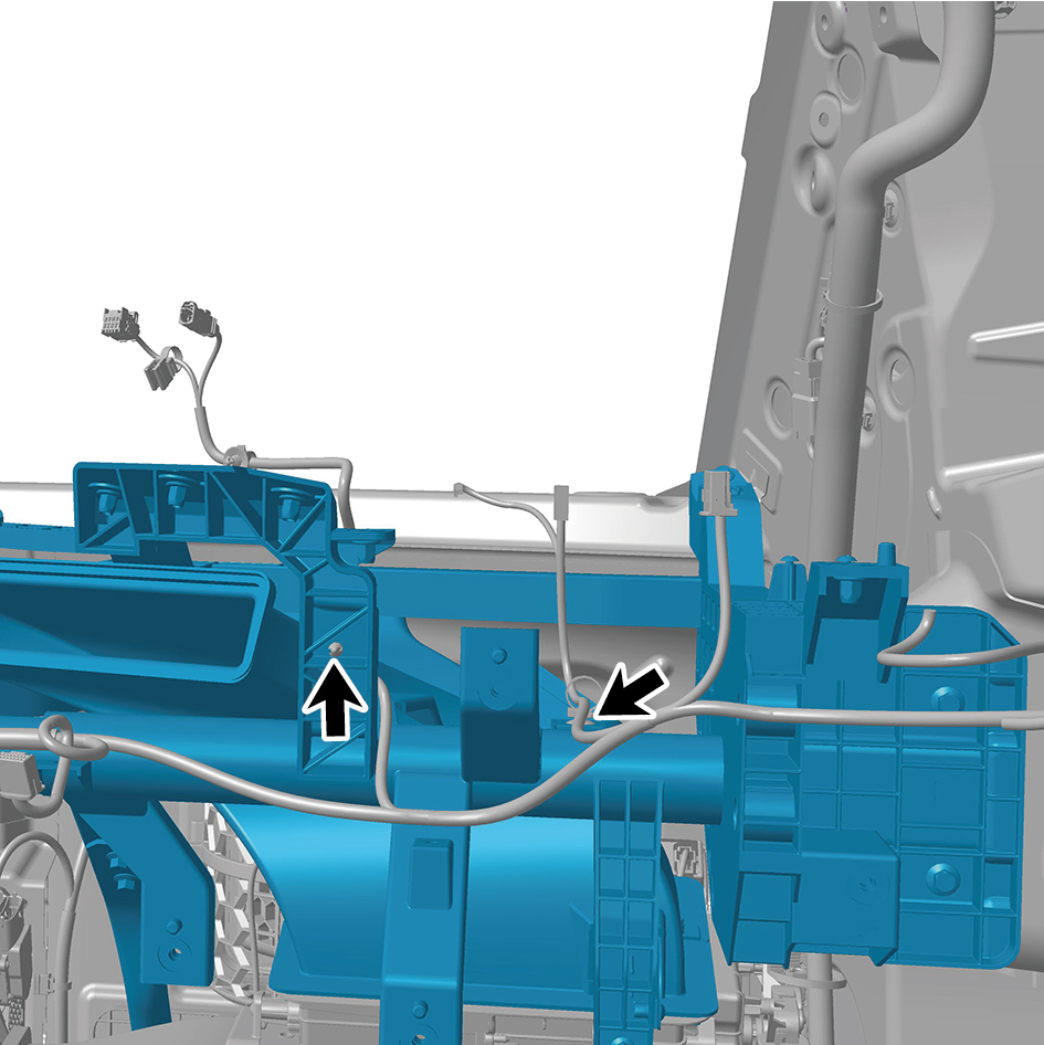
Disengage 24 fixing clips of the tubular beam assembly.
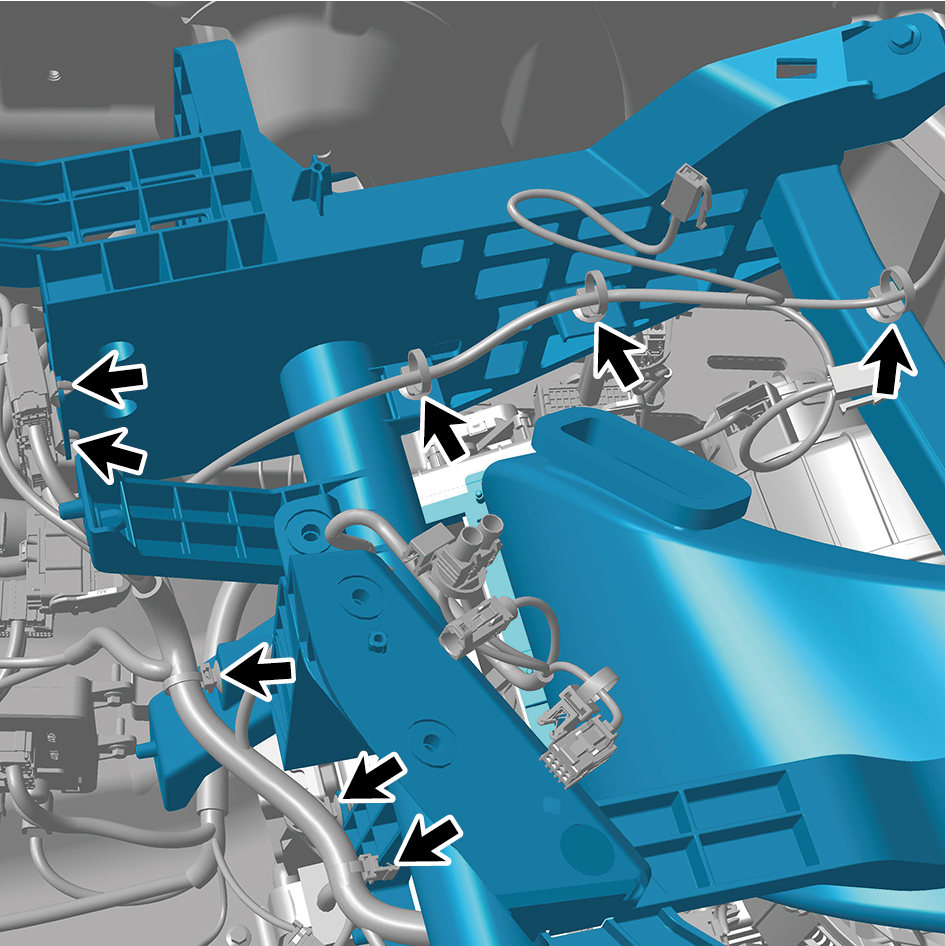
56
Remove 7 fixing bolts of the tubular beam assembly.
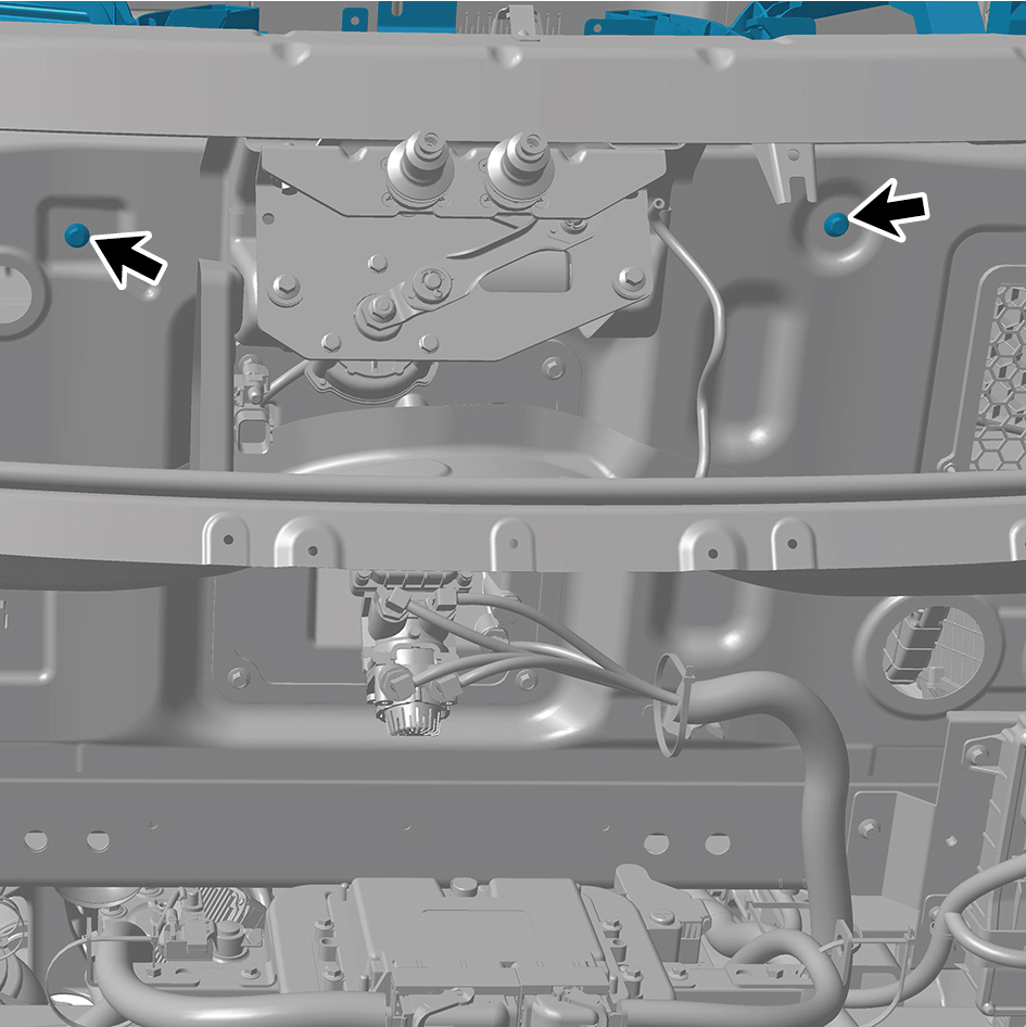
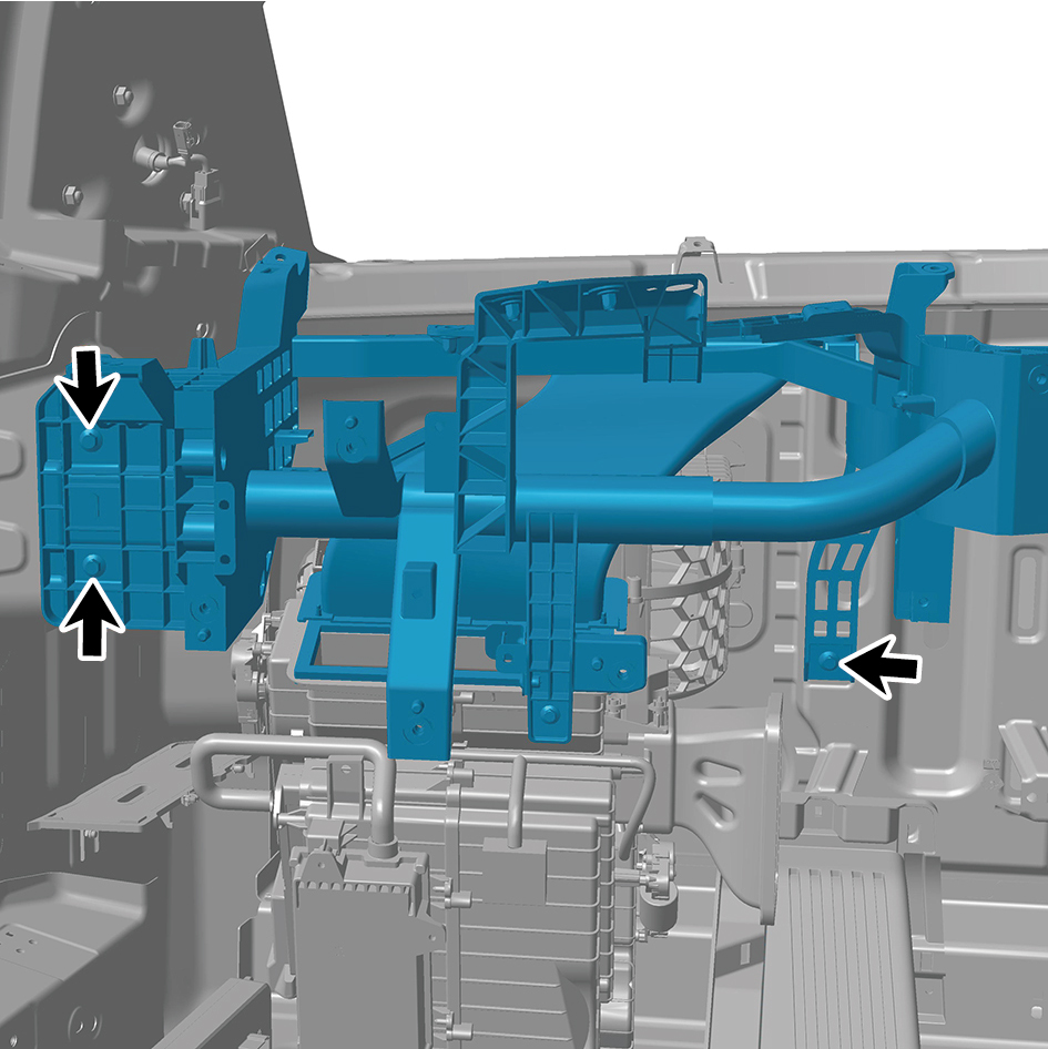
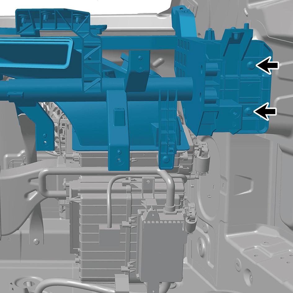
57
Remove 2 fixing bolts of the tubular beam assembly, and
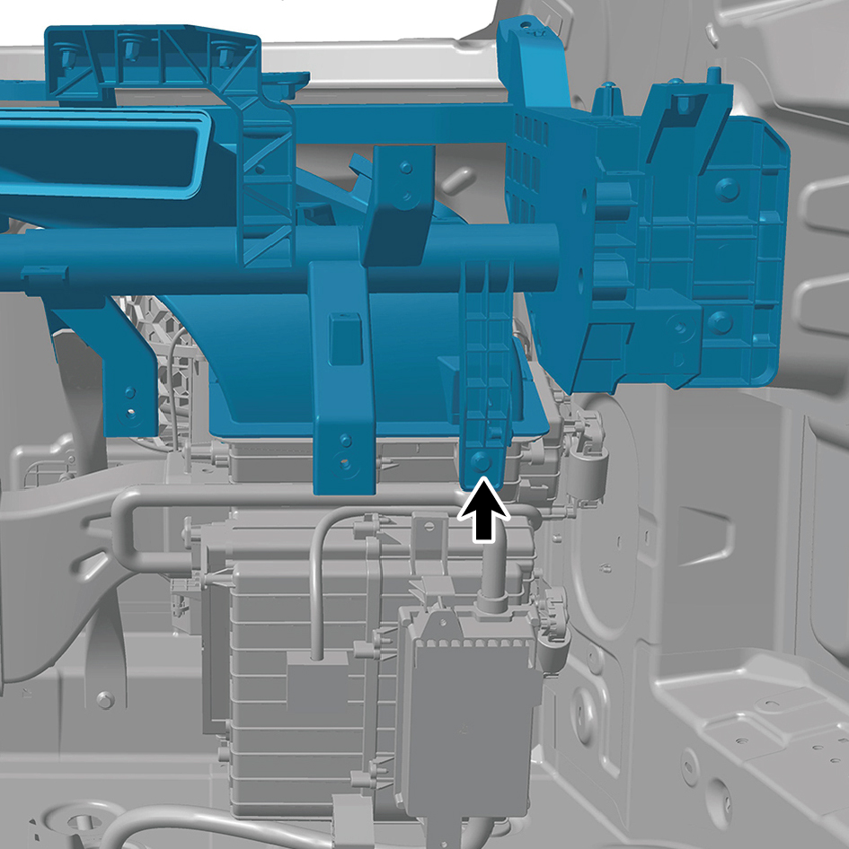
remove the tubular beam assembly.
caution
Due to the heavy weight of the tubular beam
assembly, it shall be removed with the help of an
assistant.
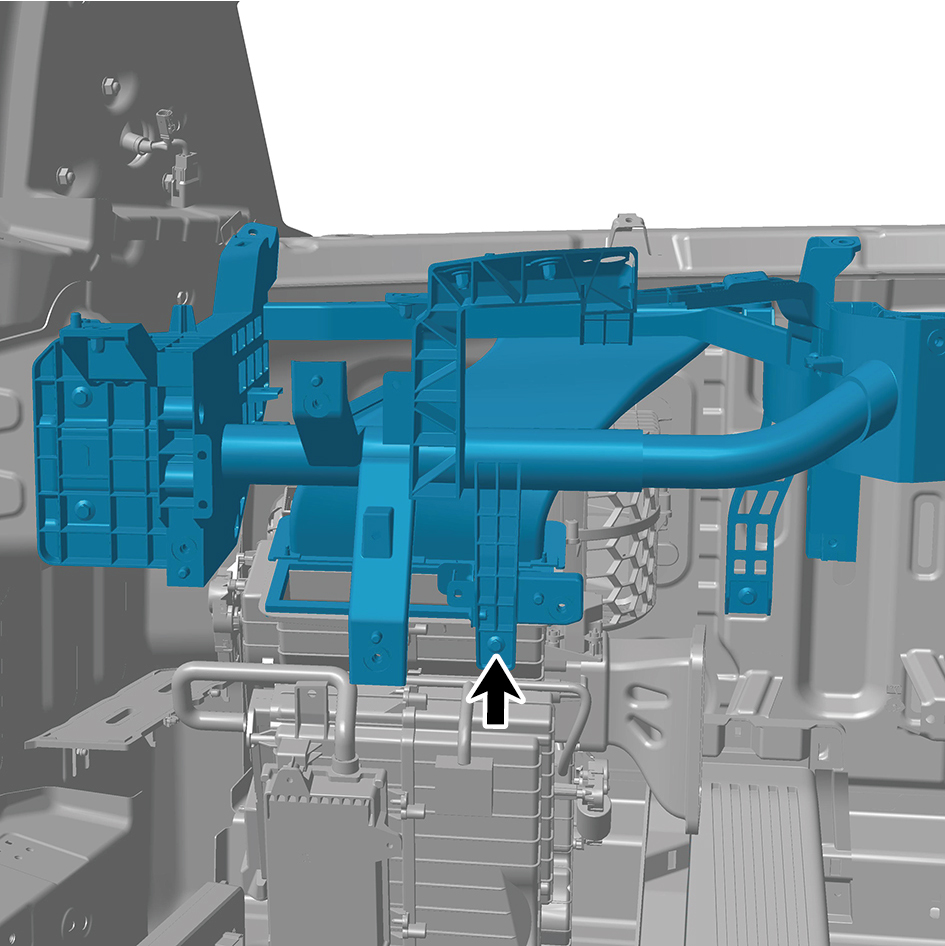
Installation Procedures
1
Move the tubular beam assembly to the mounting
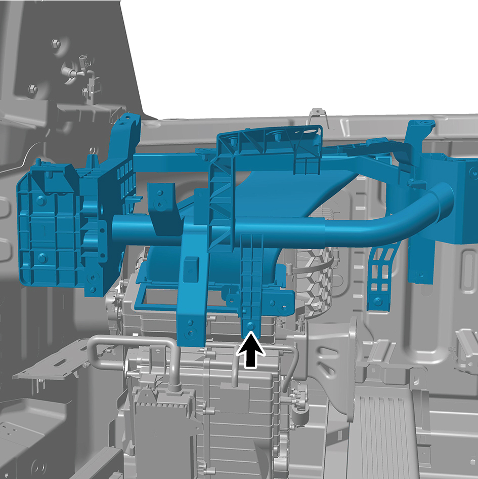
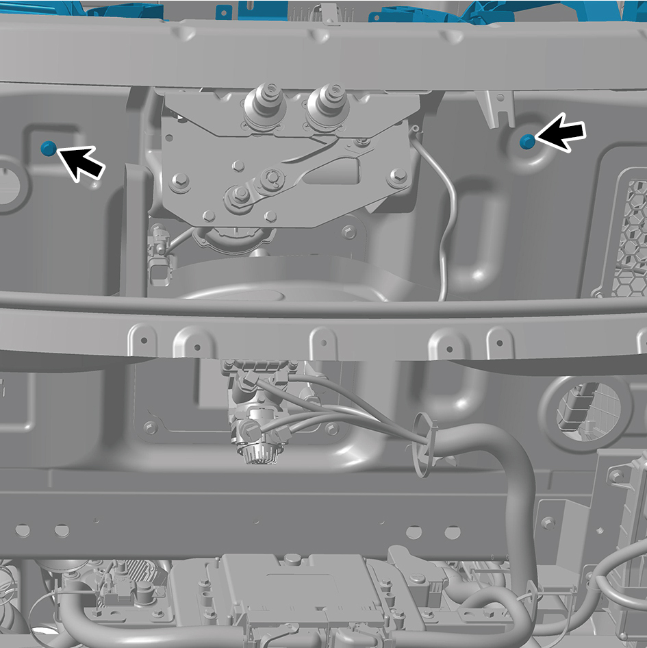
position, and install the 2 fixing bolts of the tubular beam
assembly.
Torque:(6.5 +/- .75) ft lbs
caution
Due to the heavy weight of the tubular beam
assembly, it shall be moved to the mounting position
with the help of an assistant.
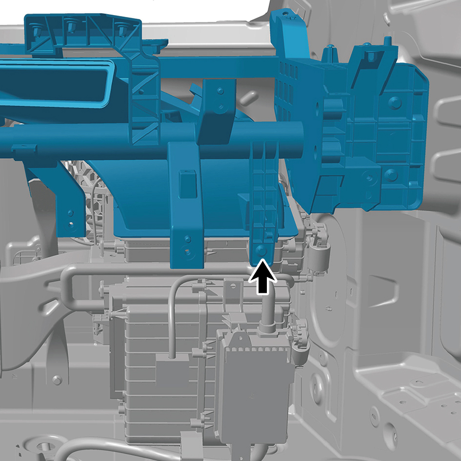
2
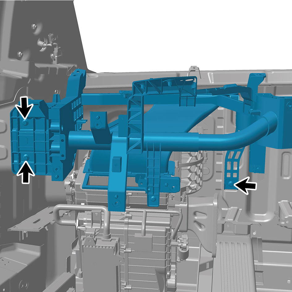
Install 7 fixing bolts of the tubular beam assembly.
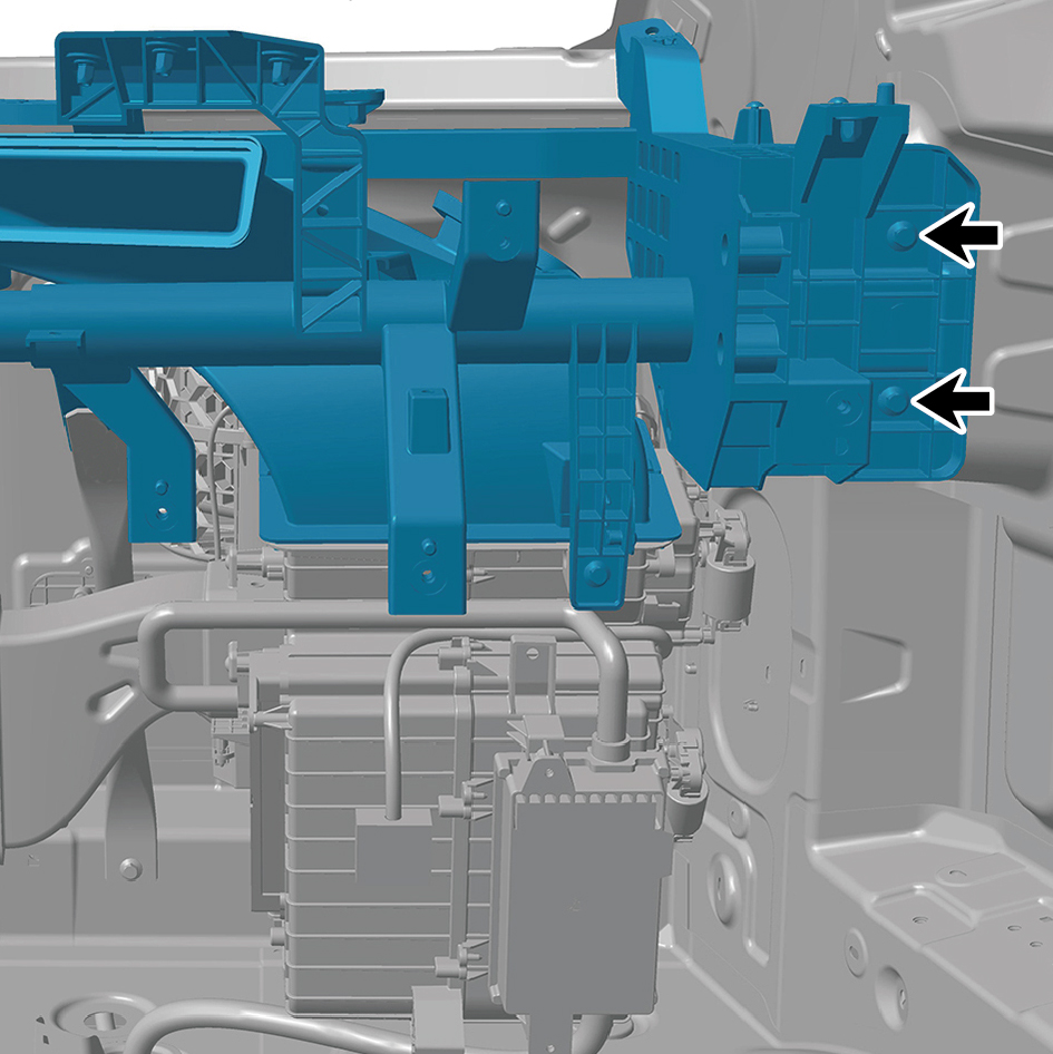
Torque:(18.5 +/- 2) ft lbs
3
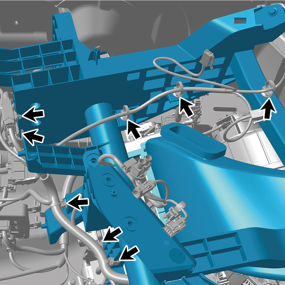
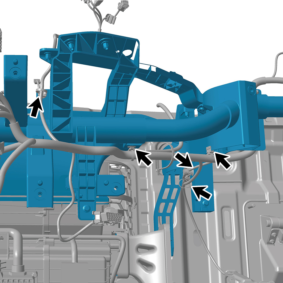
Install 24 fixing clips of the tubular beam assembly.
4
Install 2 fixing bolts connecting the combination antenna

to the tubular beam assembly.
Torque:(6.5 +/- .75) ft lbs
5
Install the cross car beam pole.
6
Install the controller bracket assy.
7
Install the body domain control unit.
8
Install the EBS bracket.
9
Install the EBS controller assy.
10
Install the Tbox-gw bracket.
11
Install the Tbox-gw.
12
Install the cockpit domain controller bracket.
13
Install the cockpit domain controller.
14
Install the smart appliance box.
15
Install the fixing bracket-lh.
16
Install the AR-HUD.
17
Install the ontology assy under the dashboard.
18
Install the cover assy-defrost frt.
19
Install the decorative plate assy-dashboard-rh frt.
20
Install the lor trim assy-dashboard-rh frt.
21
Install the trim assy-dashboard-lh frt.
22
Install the ontology assy on the dashboard.
23
Install the air vent decorative plate assy-rh.
24
Install the storage box assy-rh.
25
Install the lower switch panel assy-rh.
26
Install the switch panel assy-rh.
27
Install the cover assy-dashboard-rh frt.
28
Install the front side enclosure assy-rh.
29
Install the assembly of the cover assy-steering under
column guard.
30
Install the air vent decorative plate assy-lh.
31
Install the instrument panel trim panel assy- upper lh.
32
Install the vehicle travelling data recorder.
33
Install the switch panel lower trim assy-lh.
34
Install the trim assy on the switch panel-lh.
35
Install the cover assy-dashboard-lh frt.
36
Install the front side enclosure assy-lh.
37
Install the assembly of the instrument panel trim panel
assy- lowerr lh.
38
Install the a-pillar guard assy-rh.
39
Install the a-pillar guard assy-lh.
40
Install the base-rh display brkt.
41
Install the camera monitor screen-rh.
42
Install the upr cover- rh camera brkt.
43
Install the base-lh display brkt.
44
Install the camera monitor screen.
45
Install the upr cover- lh camera brkt.
46
Install the IPC screen.
47
Install the CAR screen.
48
Install the IVI screen.
49
Install the ip brim assy.
50
Install the cover-combination switch-lor.
51
Install the steering wheel assy.
52
Install the dab decorative cove.
53
Install the assembly of the front windshield cover.
54
Install the wiper arm assy.
55
Connect the battery negative cable.
56
Close the front flip cover plate.
57
Close the door.
6.11.3.2 Replacement of Tubular Beam Strut
Removal Procedures
1
Open the door.
2
Remove the IP right access cover plate assembly.
3
Remove the right foot blowing duct assembly.
4
Remove 3 fixing bolts of the tubular beam strut, and
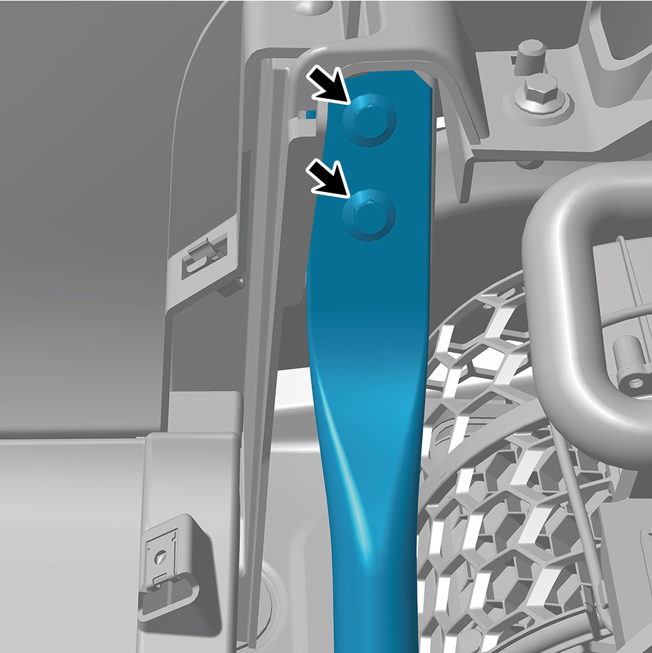
remove the tubular beam strut.
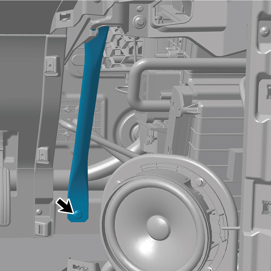
Installation Procedures
1
Move the tubular beam strut to the mounting position.
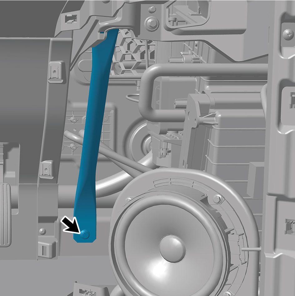
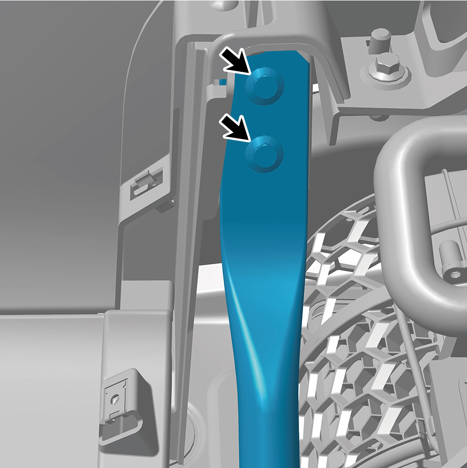
2
Install 3 fixing bolts of the tubular beam strut.
Torque:(18.5 +/- 2) ft lbs
3
Install the right foot blowing duct assembly.
4
Install the IP right access cover plate assembly.
5
Close the door.
6.11.3.3 Replacement of Left Defroster Duct Assembly
Assembly
Removal Procedures
1
Open the door.
2
Open the front flip cover plate.
3
Disconnect the battery negative cable.
caution
power down the high-voltage system before
disconnecting the negative pole of the storage
battery.
4
Remove the wiper arm assy.
5
Remove the assembly of the front windshield cover.
6
Remove the dab decorative cove.
7
Remove the steering wheel assy.
8
Remove the cover-combination switch-lor.
9
Remove the ip brim assy.
10
Remove the IVI screen.
11
Remove the CAR screen.
12
Remove the IPC screen.
13
Remove the upr cover- lh camera brkt.
14
Remove the camera monitor screen.
15
Remove the base-lh display brkt.
16
Remove the upr cover- rh camera brkt.
17
Remove the camera monitor screen-rh.
18
Remove the base-rh display brkt.
19
Remove the a-pillar guard assy-lh.
20
Remove the a-pillar guard assy-rh.
21
Remove the assembly of the instrument panel trim panel
assy- lowerr lh.
22
Remove the front side enclosure assy-lh.
23
Remove the cover assy-dashboard-lh frt.
24
Remove the trim assy on the switch panel-lh.
25
Remove the switch panel lower trim assy-lh.
26
Remove the vehicle travelling data recorder.
27
Remove the instrument panel trim panel assy- upper lh.
28
Remove the air vent decorative plate assy-lh.
29
Remove the assembly of the cover assy-steering under
column guard.
30
Remove the front side enclosure assy-rh.
31
Remove the cover assy-dashboard-rh frt.
32
Remove the switch panel assy-rh.
33
Remove the lower switch panel assy-rh.
34
Remove the storage box assy-rh.
35
Remove the air vent decorative plate assy-rh.
36
Remove the ontology assy on the dashboard.
37
Remove the trim assy-dashboard-lh frt.
38
Remove the lor trim assy-dashboard-rh frt.
39
Remove the decorative plate assy-dashboard-rh frt.
40
Remove the cover assy-defrost frt.
41
Remove the ontology assy under the dashboard.
42
Remove the AR-HUD.
43
Remove the fixing bracket-lh.
44
Remove the smart appliance box.
45
Remove the cockpit domain controller.
46
Remove the cockpit domain controller bracket.
47
Remove the Tbox-gw.
48
Remove the Tbox-gw bracket.
49
Remove the EBS controller assy.
50
Remove the EBS bracket.
51
Remove the body domain control unit.
52
Remove the controller bracket assy.
53
Remove the cross car beam pole.
54
Remove the cross car beam assy.
55
Remove 2 fixing screws of the left defroster duct
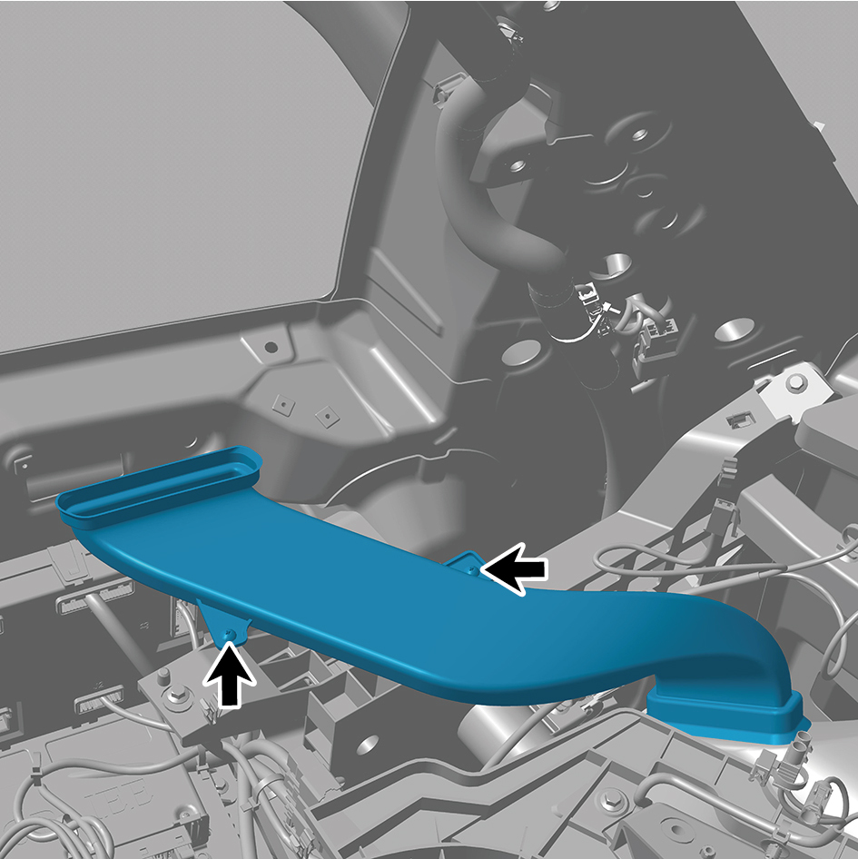
assembly.
56
Remove the left defroster duct assembly.
Installation Procedures
1
Move the left defroster duct assembly to the mounting
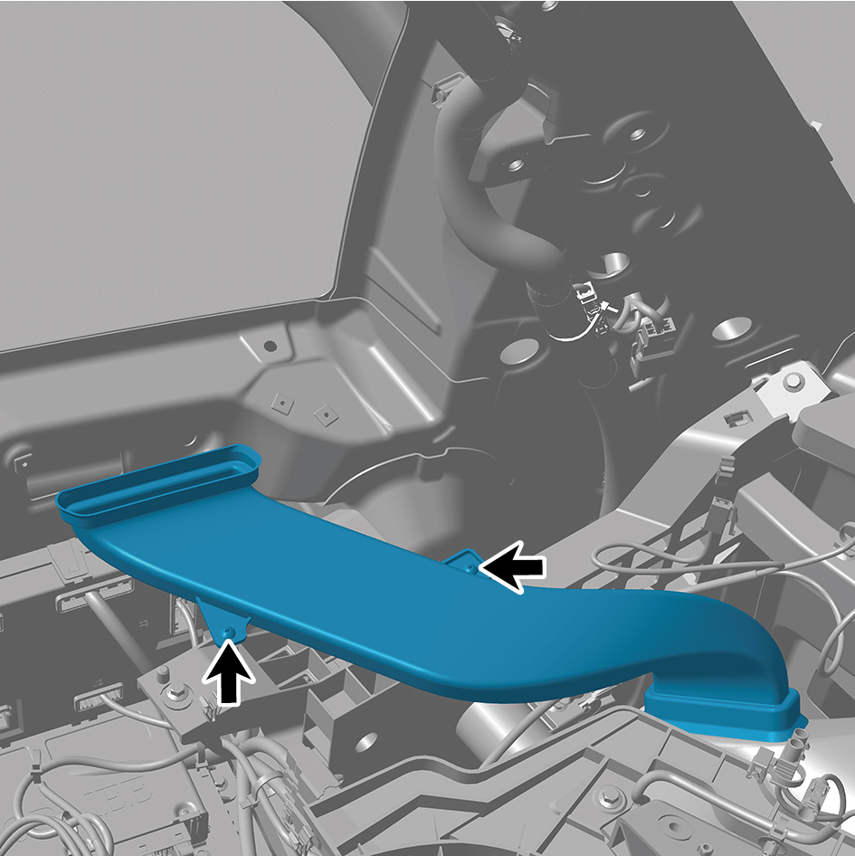
position.
2
Install 2 fixing screws of the left defroster duct assembly.
3
Install the cross car beam assy.
4
Install the cross car beam pole.
5
Install the controller bracket assy.
6
Install the body domain control unit.
7
Install the EBS bracket.
8
Install the EBS controller assy.
9
Install the Tbox-gw bracket.
10
Install the Tbox-gw.
11
Install the cockpit domain controller bracket.
12
Install the cockpit domain controller.
13
Install the smart appliance box.
14
Install the fixing bracket-lh.
15
Install the AR-HUD.
16
Install the ontology assy under the dashboard.
17
Install the cover assy-defrost frt.
18
Install the decorative plate assy-dashboard-rh frt.
19
Install the lor trim assy-dashboard-rh frt.
20
Install the trim assy-dashboard-lh frt.
21
Install the ontology assy on the dashboard.
22
Install the air vent decorative plate assy-rh.
23
Install the storage box assy-rh.
24
Install the lower switch panel assy-rh.
25
Install the switch panel assy-rh.
26
Install the cover assy-dashboard-rh frt.
27
Install the front side enclosure assy-rh.
28
Install the assembly of the cover assy-steering under
column guard.
29
Install the air vent decorative plate assy-lh.
30
Install the instrument panel trim panel assy- upper lh.
31
Install the vehicle travelling data recorder.
32
Install the switch panel lower trim assy-lh.
33
Install the trim assy on the switch panel-lh.
34
Install the cover assy-dashboard-lh frt.
35
Install the front side enclosure assy-lh.
36
Install the assembly of the instrument panel trim panel
assy- lowerr lh.
37
Install the a-pillar guard assy-rh.
38
Install the a-pillar guard assy-lh.
39
Install the base-rh display brkt.
40
Install the camera monitor screen-rh.
41
Install the upr cover- rh camera brkt.
42
Install the base-lh display brkt.
43
Install the camera monitor screen.
44
Install the upr cover- lh camera brkt.
45
Install the IPC screen.
46
Install the CAR screen.
47
Install the IVI screen.
48
Install the ip brim assy.
49
Install the cover-combination switch-lor.
50
Install the steering wheel assy.
51
Install the dab decorative cove.
52
Install the assembly of the front windshield cover.
53
Install the wiper arm assy.
54
Connect the battery negative cable.
55
Close the front flip cover plate.
56
Close the door.
6.11.3.4 Replacement of Right Defroster Duct Assembly
Assembly
Removal Procedures
1
Open the door.
2
Open the front flip cover plate.
3
Disconnect the battery negative cable.
caution
power down the high-voltage system before
disconnecting the negative pole of the storage
battery.
4
Remove the wiper arm assy.
5
Remove the assembly of the front windshield cover.
6
Remove the dab decorative cove.
7
Remove the steering wheel assy.
8
Remove the cover-combination switch-lor.
9
Remove the ip brim assy.
10
Remove the IVI screen.
11
Remove the CAR screen.
12
Remove the IPC screen.
13
Remove the upr cover- lh camera brkt.
14
Remove the camera monitor screen.
15
Remove the base-lh display brkt.
16
Remove the upr cover- rh camera brkt.
17
Remove the camera monitor screen-rh.
18
Remove the base-rh display brkt.
19
Remove the a-pillar guard assy-lh.
20
Remove the a-pillar guard assy-rh.
21
Remove the assembly of the instrument panel trim panel
assy- lowerr lh.
22
Remove the front side enclosure assy-lh.
23
Remove the cover assy-dashboard-lh frt.
24
Remove the trim assy on the switch panel-lh.
25
Remove the switch panel lower trim assy-lh.
26
Remove the vehicle travelling data recorder.
27
Remove the instrument panel trim panel assy- upper lh.
28
Remove the air vent decorative plate assy-lh.
29
Remove the assembly of the cover assy-steering under
column guard.
30
Remove the front side enclosure assy-rh.
31
Remove the cover assy-dashboard-rh frt.
32
Remove the switch panel assy-rh.
33
Remove the lower switch panel assy-rh.
34
Remove the storage box assy-rh.
35
Remove the air vent decorative plate assy-rh.
36
Remove the ontology assy on the dashboard.
37
Remove the trim assy-dashboard-lh frt.
38
Remove the lor trim assy-dashboard-rh frt.
39
Remove the decorative plate assy-dashboard-rh frt.
40
Remove the cover assy-defrost frt.
41
Remove the ontology assy under the dashboard.
42
Remove the AR-HUD.
43
Remove the fixing bracket-lh.
44
Remove the smart appliance box.
45
Remove the cockpit domain controller.
46
Remove the cockpit domain controller bracket.
47
Remove the Tbox-gw.
48
Remove the Tbox-gw bracket.
49
Remove the EBS controller assy.
50
Remove the EBS bracket.
51
Remove the body domain control unit.
52
Remove the controller bracket assy.
53
Remove the cross car beam pole.
54
Remove the cross car beam assy.
55
Remove 2 fixing screws of the right defroster duct
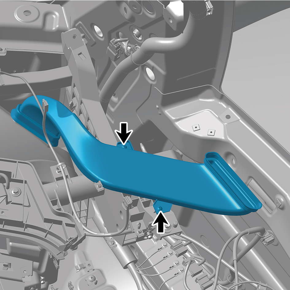
assembly.
56
Remove the right defroster duct assembly.
Installation Procedures
1
Move the right defroster duct assembly to the mounting
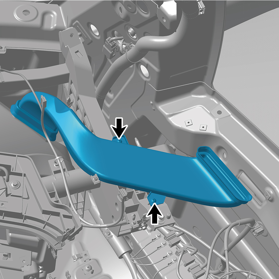
position.
2
Install 2 fixing screws of the right defroster duct assembly.
3
Install the cross car beam assy.
4
Install the cross car beam pole.
5
Install the controller bracket assy.
6
Install the body domain control unit.
7
Install the EBS bracket.
8
Install the EBS controller assy.
9
Install the Tbox-gw bracket.
10
Install the Tbox-gw.
11
Install the cockpit domain controller bracket.
12
Install the cockpit domain controller.
13
Install the smart appliance box.
14
Install the fixing bracket-lh.
15
Install the AR-HUD.
16
Install the ontology assy under the dashboard.
17
Install the cover assy-defrost frt.
18
Install the decorative plate assy-dashboard-rh frt.
19
Install the lor trim assy-dashboard-rh frt.
20
Install the trim assy-dashboard-lh frt.
21
Install the ontology assy on the dashboard.
22
Install the air vent decorative plate assy-rh.
23
Install the storage box assy-rh.
24
Install the lower switch panel assy-rh.
25
Install the switch panel assy-rh.
26
Install the cover assy-dashboard-rh frt.
27
Install the front side enclosure assy-rh.
28
Install the assembly of the cover assy-steering under
column guard.
29
Install the air vent decorative plate assy-lh.
30
Install the instrument panel trim panel assy- upper lh.
31
Install the vehicle travelling data recorder.
32
Install the switch panel lower trim assy-lh.
33
Install the trim assy on the switch panel-lh.
34
Install the cover assy-dashboard-lh frt.
35
Install the front side enclosure assy-lh.
36
Install the assembly of the instrument panel trim panel
assy- lowerr lh.
37
Install the a-pillar guard assy-rh.
38
Install the a-pillar guard assy-lh.
39
Install the base-rh display brkt.
40
Install the camera monitor screen-rh.
41
Install the upr cover- rh camera brkt.
42
Install the base-lh display brkt.
43
Install the camera monitor screen.
44
Install the upr cover- lh camera brkt.
45
Install the IPC screen.
46
Install the CAR screen.
47
Install the IVI screen.
48
Install the ip brim assy.
49
Install the cover-combination switch-lor.
50
Install the steering wheel assy.
51
Install the dab decorative cove.
52
Install the assembly of the front windshield cover.
53
Install the wiper arm assy.
54
Connect the battery negative cable.
55
Close the front flip cover plate.
56
Close the door.
6.11.3.5 Replacement of IP Lower Body Assembly
Assembly
Removal Procedures
1
Open the door.
2
Open the front flip cover plate.
3
Disconnect the battery negative cable.
caution
power down the high-voltage system before
disconnecting the negative pole of the storage
battery.
4
Remove the dab decorative cove.
5
Remove the steering wheel assy.
6
Remove the cover-combination switch-lor.
7
Remove the ip brim assy.
8
Remove the ivi screen.
9
Remove the car screen.
10
Remove the ipc screen.
11
Remove the upr cover- lh camera brkt.
12
Remove the camera monitor screen.
13
Remove the base-lh display brkt.
14
Remove the upr cover- rh camera brkt.
15
Remove the camera monitor screen-rh.
16
Remove the base-rh display brkt.
17
Remove the a-pillar guard assy-lh.
18
Remove the a-pillar guard assy-rh.
19
Remove the assembly of the instrument panel trim panel
assy- lowerr lh.
20
Remove the front side enclosure assy-lh.
21
Remove the cover assy-dashboard-lh frt.
22
Remove the trim assy on the switch panel-lh.
23
Remove the switch panel lower trim assy-lh.
24
Remove the vehicle travelling data recorder.
25
Remove the instrument panel trim panel assy- upper lh.
26
Remove the air vent decorative plate assy-lh.
27
Remove the assembly of the cover assy-steering under
column guard.
28
Remove the front side enclosure assy-rh.
29
Remove the cover assy-dashboard-rh frt.
30
Remove the switch panel assy-rh.
31
Remove the lower switch panel assy-rh.
32
Remove the storage box assy-rh.
33
Remove the air vent decorative plate assy-rh.
34
Remove the ontology assy on the dashboard.
35
Remove the trim assy-dashboard-lh frt.
36
Remove the lor trim assy-dashboard-rh frt.
37
Remove the decorative plate assy-dashboard-rh frt.
38
Remove the cover assy-defrost frt.
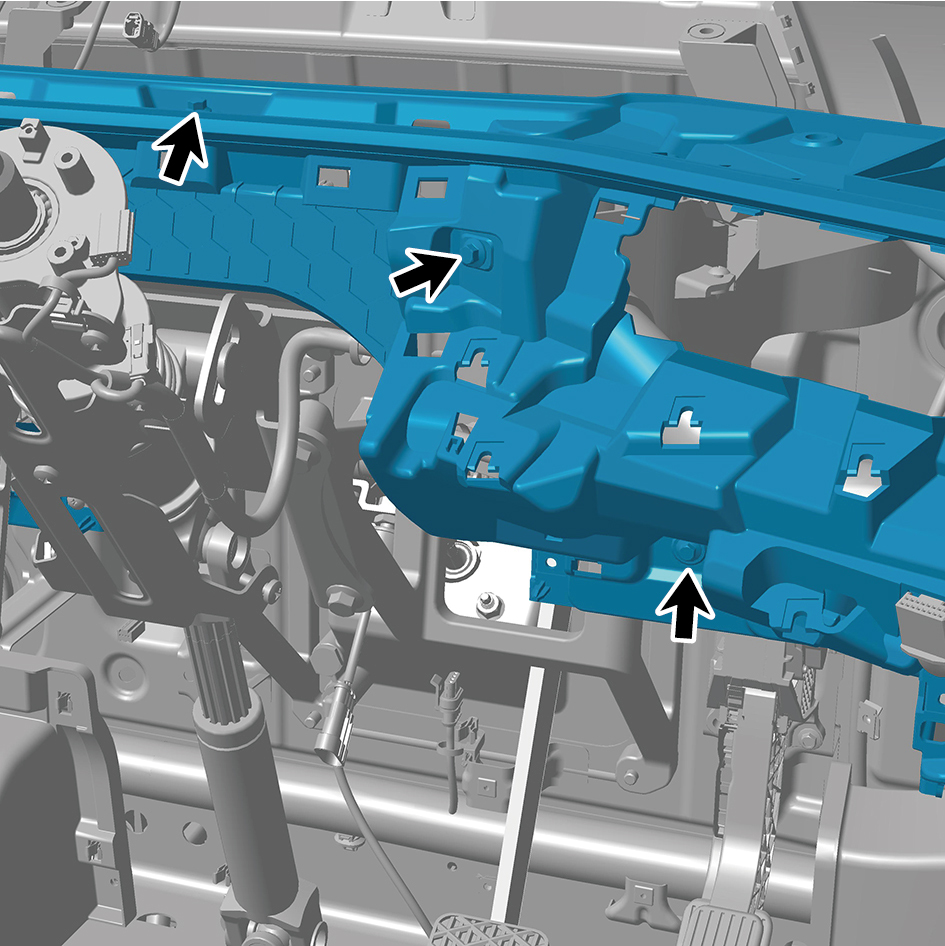
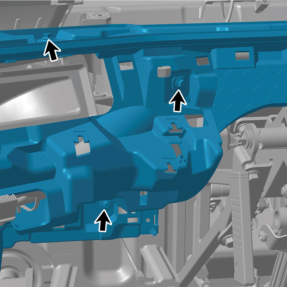
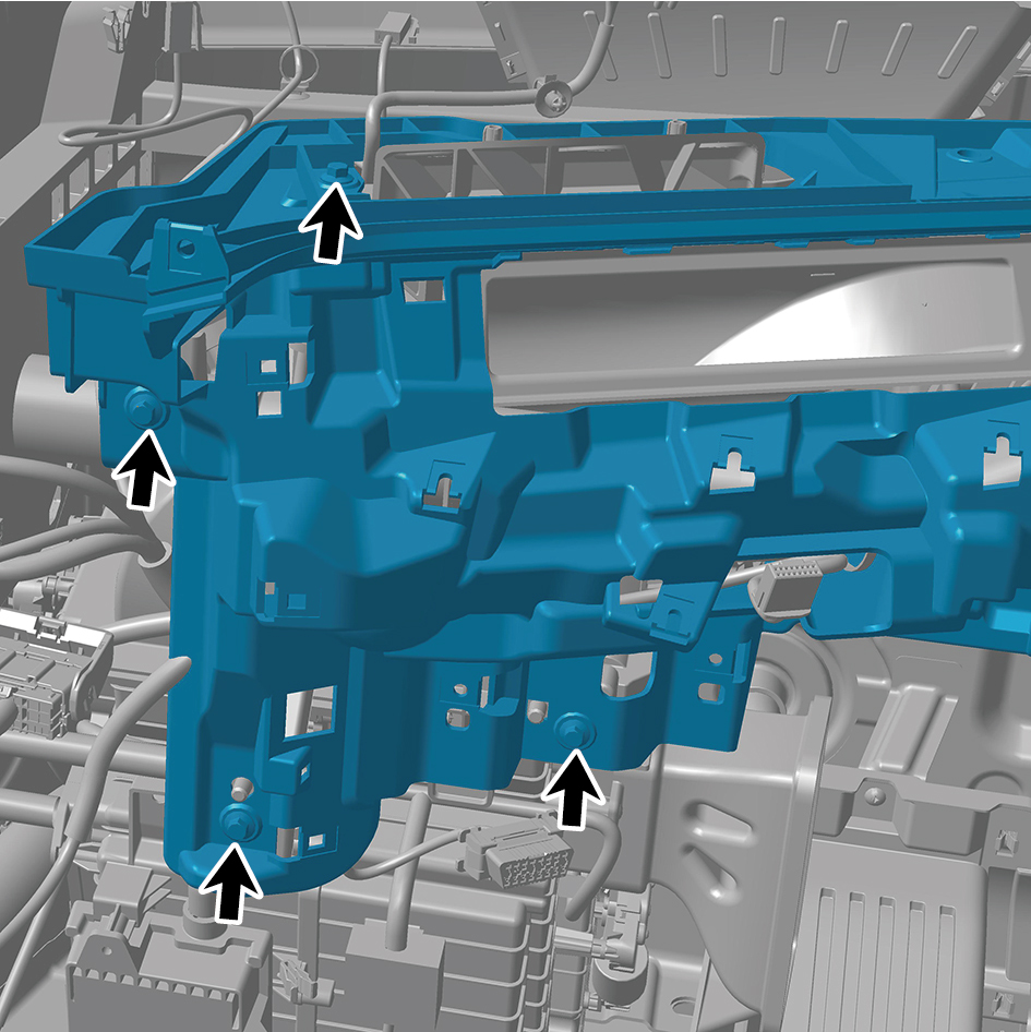
49
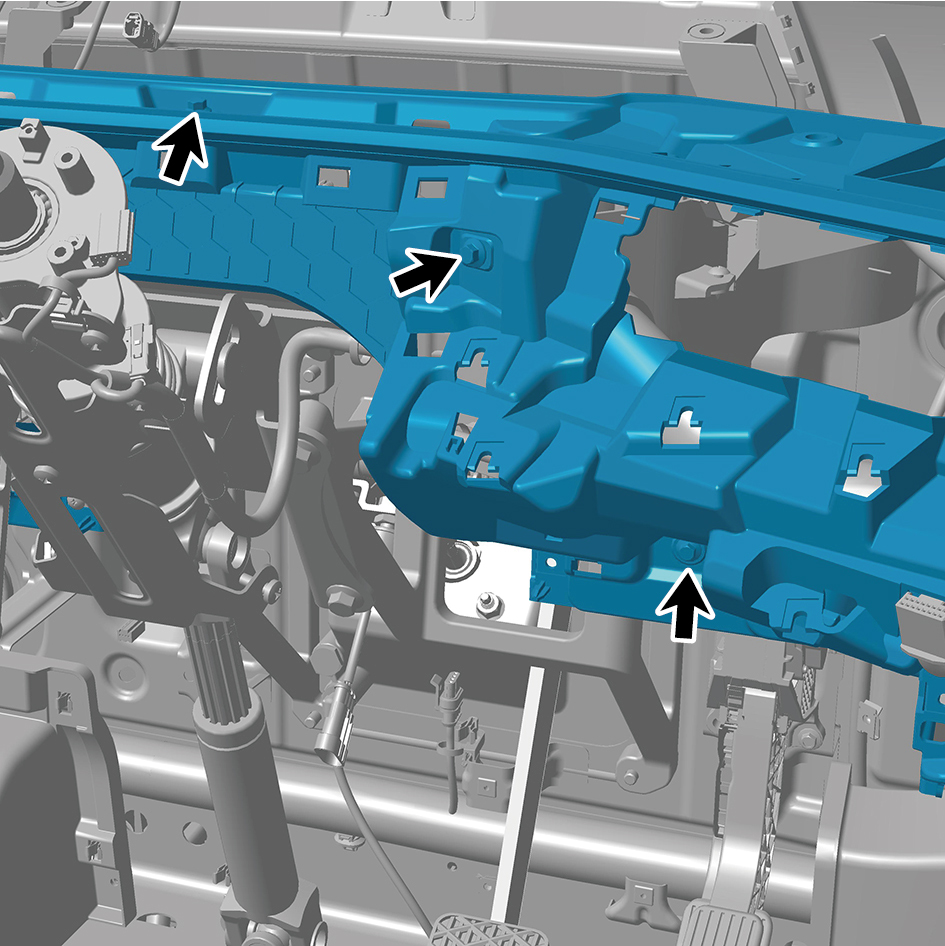
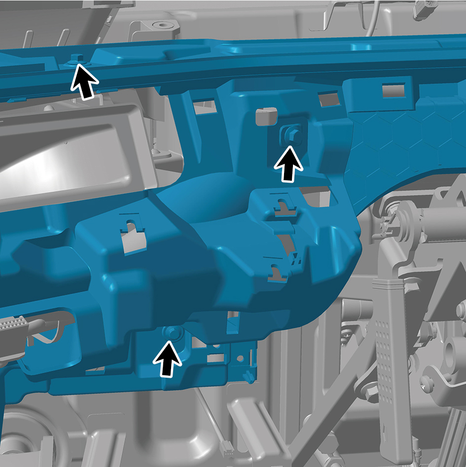
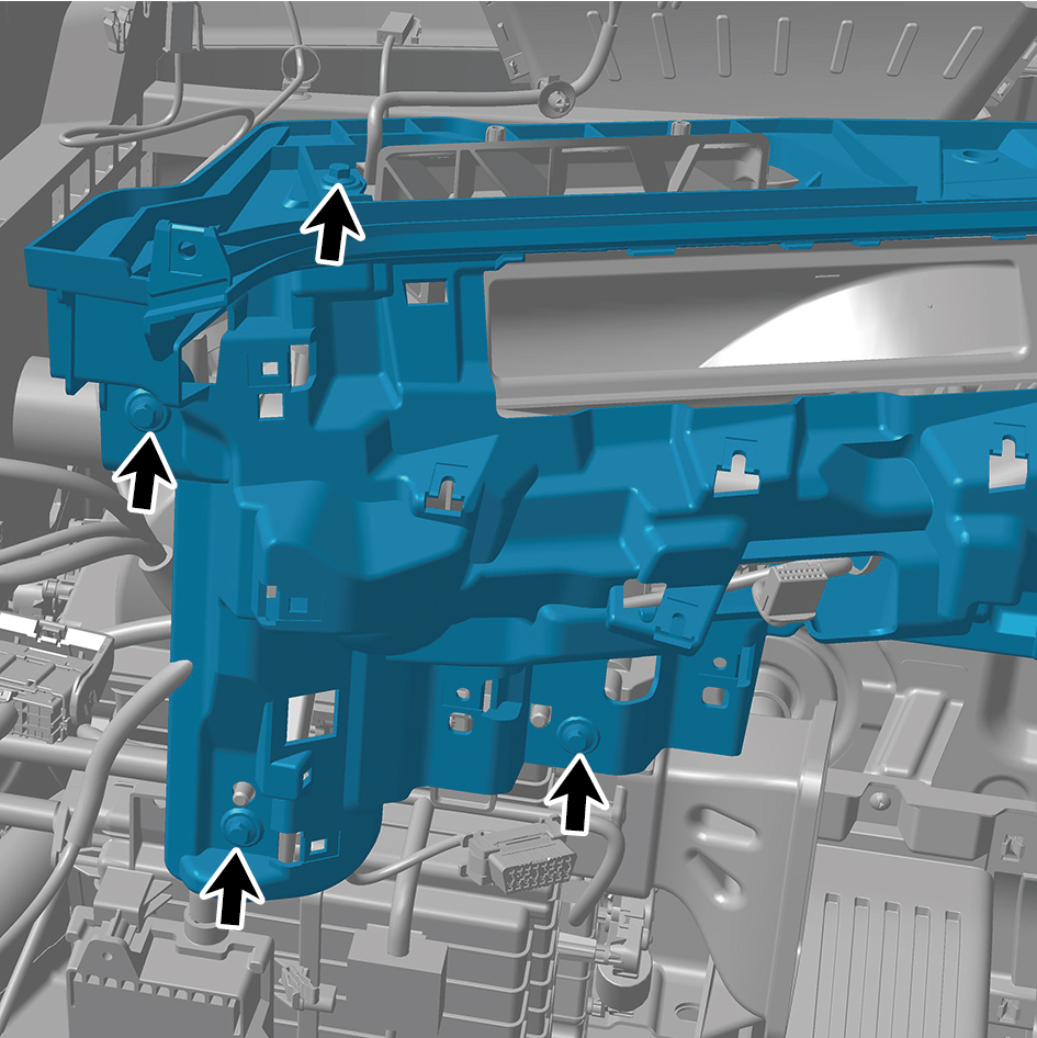
Remove 15 fixing bolts of the IP lower body assembly, and
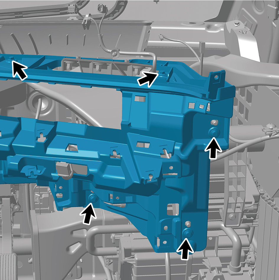
remove the IP lower body assembly.
Installation Procedures
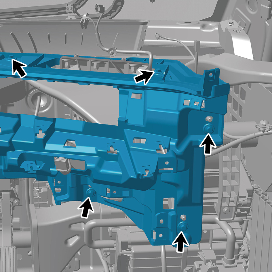
1
Move the IP lower body assembly to the mounting
position.
2
Install 15 fixing bolts of the IP lower body assembly.
Torque: (6.5 +/- .75) ft lbs
3
Install the cover assy-defrost frt.
4
Install the decorative plate assy-dashboard-rh frt.
5
Install the lor trim assy-dashboard-rh frt.
6
Install the trim assy-dashboard-lh frt.
7
Install the ontology assy on the dashboard.
8
Install the air vent decorative plate assy-rh.
9
Install the storage box assy-rh.
10
Install the lower switch panel assy-rh.
11
Install the switch panel assy-rh.
12
Install the cover assy-dashboard-rh frt.
13
Install the front side enclosure assy-rh.
14
Install the assembly of the cover assy-steering under
column guard.
15
Install the air vent decorative plate assy-lh.
16
Install the instrument panel trim panel assy- upper lh.
17
Install the vehicle travelling data recorder.
18
Install the switch panel lower trim assy-lh.
19
Install the trim assy on the switch panel-lh.
20
Install the cover assy-dashboard-lh frt.
21
Install the front side enclosure assy-lh.
22
Install the assembly of the instrument panel trim panel
assy- lowerr lh.
23
Install the a-pillar guard assy-rh.
24
Install the a-pillar guard assy-lh.
25
Install the base-rh display brkt.
26
Install the camera monitor screen-rh.
27
Install the upr cover- rh camera brkt.
28
Install the base-lh display brkt.
29
Install the camera monitor screen.
30
Install the upr cover- lh camera brkt.
31
Install the ipc screen.
32
Install the car screen.
33
Install the ivi screen.
34
Install the ip brim assy.
35
Install the cover-combination switch-lor.
36
Install the steering wheel assy.
37
Install the dab decorative cove.
38
Connect the battery negative cable.
39
Close the front flip cover plate.
40
Close the door.
6.11.3.6 Replacement of IP Upper Body Assembly
Assembly
Removal Procedures
1
Open the door.
2
Open the front flip cover plate.
3
Disconnect the battery negative cable.
caution
power down the high-voltage system before
disconnecting the negative pole of the storage
battery.
4
Remove the ip brim assy.
5
Remove the ivi screen.
6
Remove the car screen.
7
Remove the ipc screen.
8
Remove the upr cover- lh camera brkt.
9
Remove the camera monitor screen.
10
Remove the base-lh display brkt.
11
Remove the upr cover- rh camera brkt.
12
Remove the camera monitor screen-rh.
13
Remove the base-rh display brkt.
14
Remove the a-pillar guard assy-lh.
15
Remove the a-pillar guard assy-rh.
16
Remove the assembly of the instrument panel trim panel
assy- lowerr lh.
17
Remove the front side enclosure assy-lh.
18
Remove the assembly of the cover assy-steering under
column guard.
19
Remove the front side enclosure assy-rh.
20
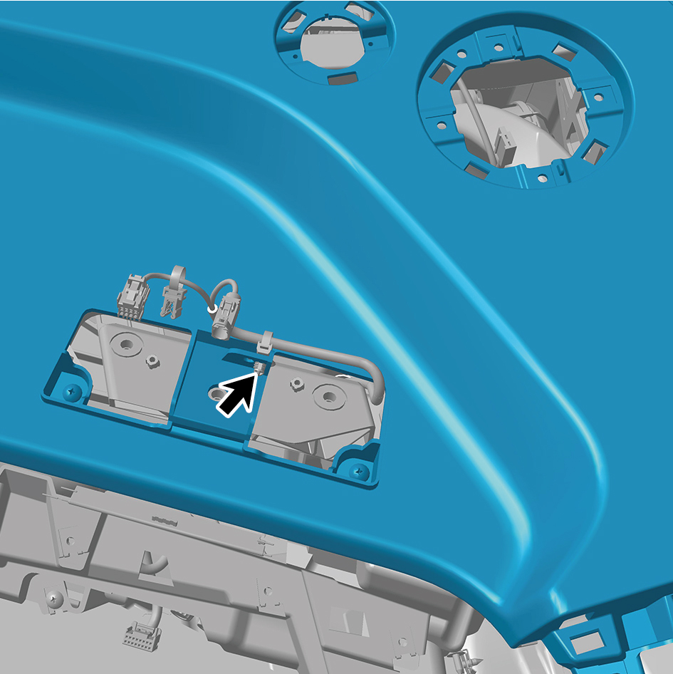
Disengage 2 fixing clips of the IP upper body assembly.
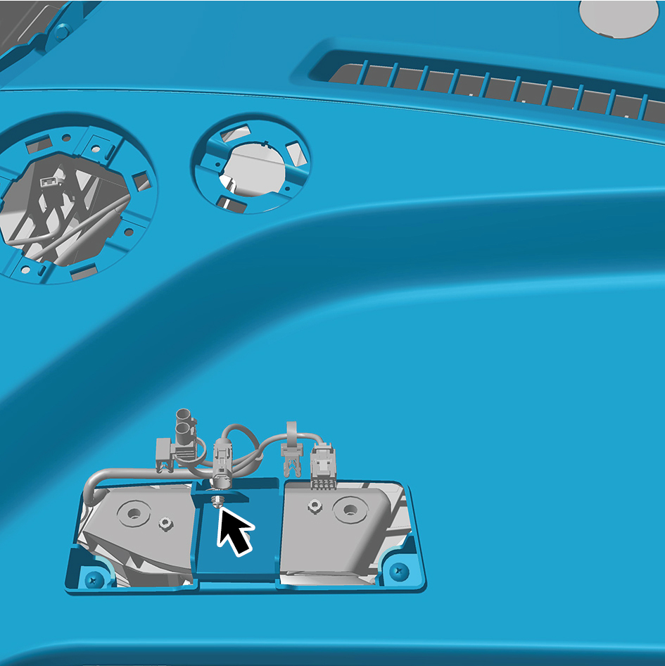
21
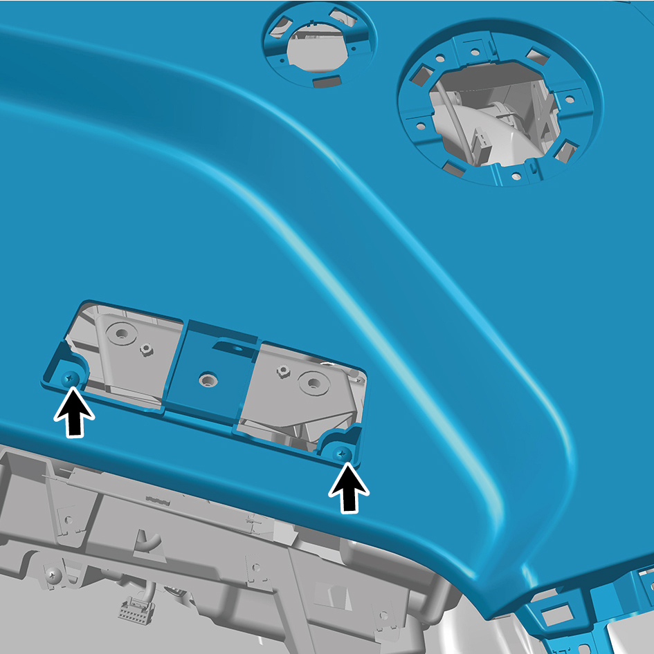
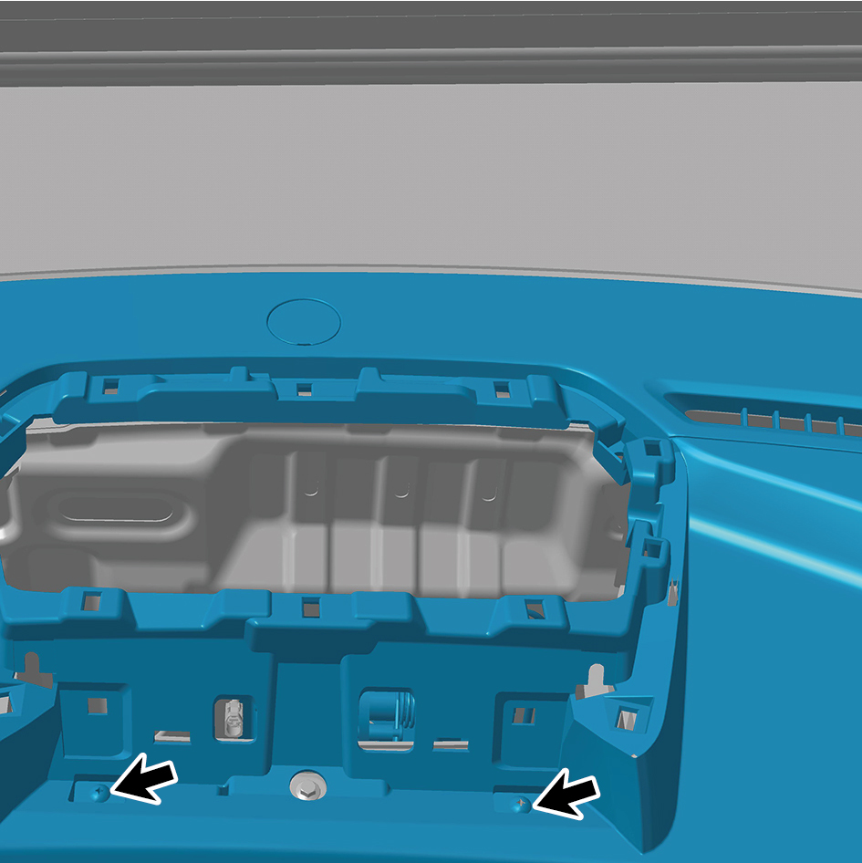
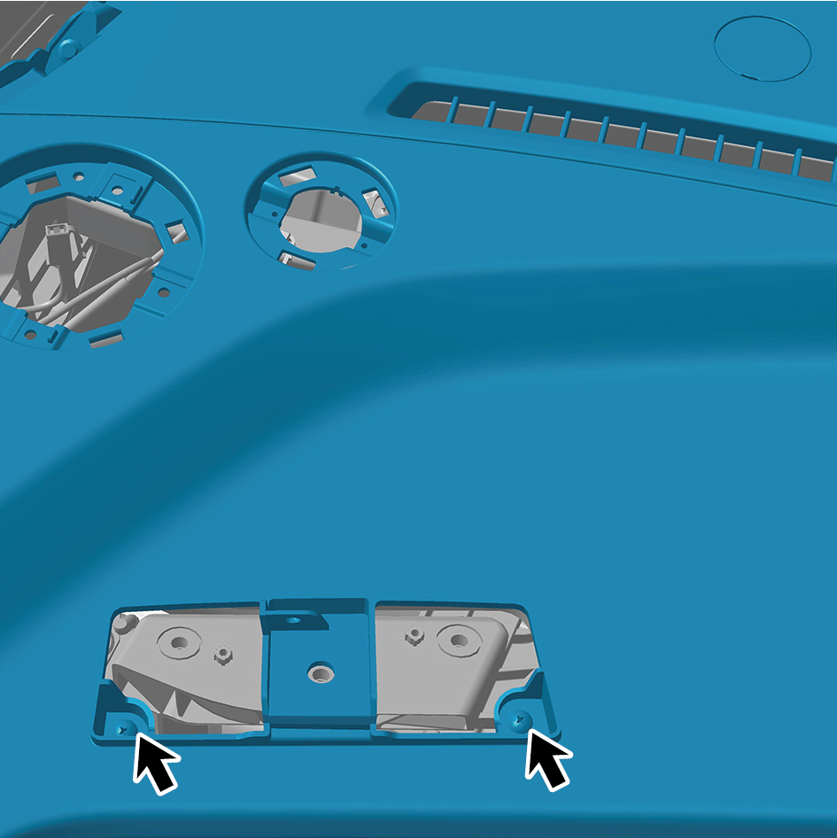
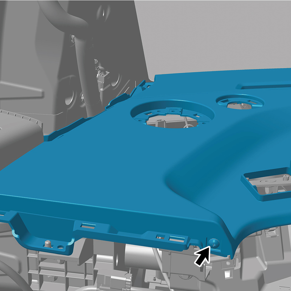
Remove 4 fixing bolts of the IP upper body assembly.
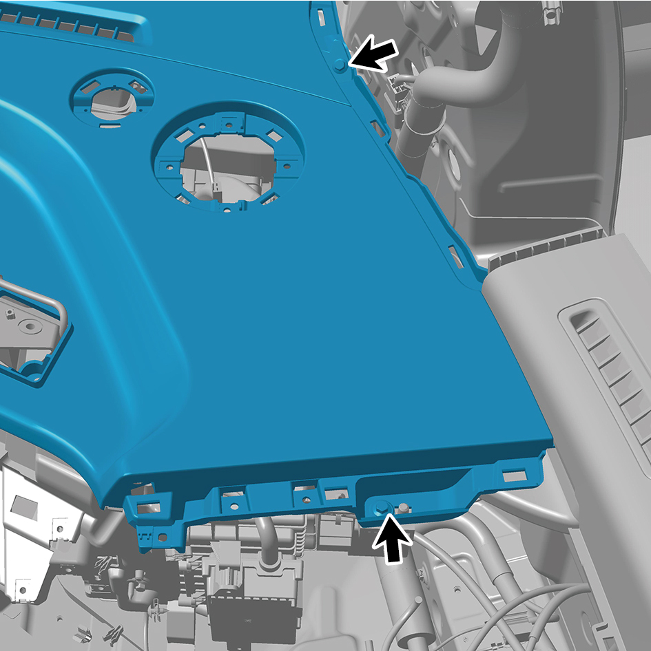
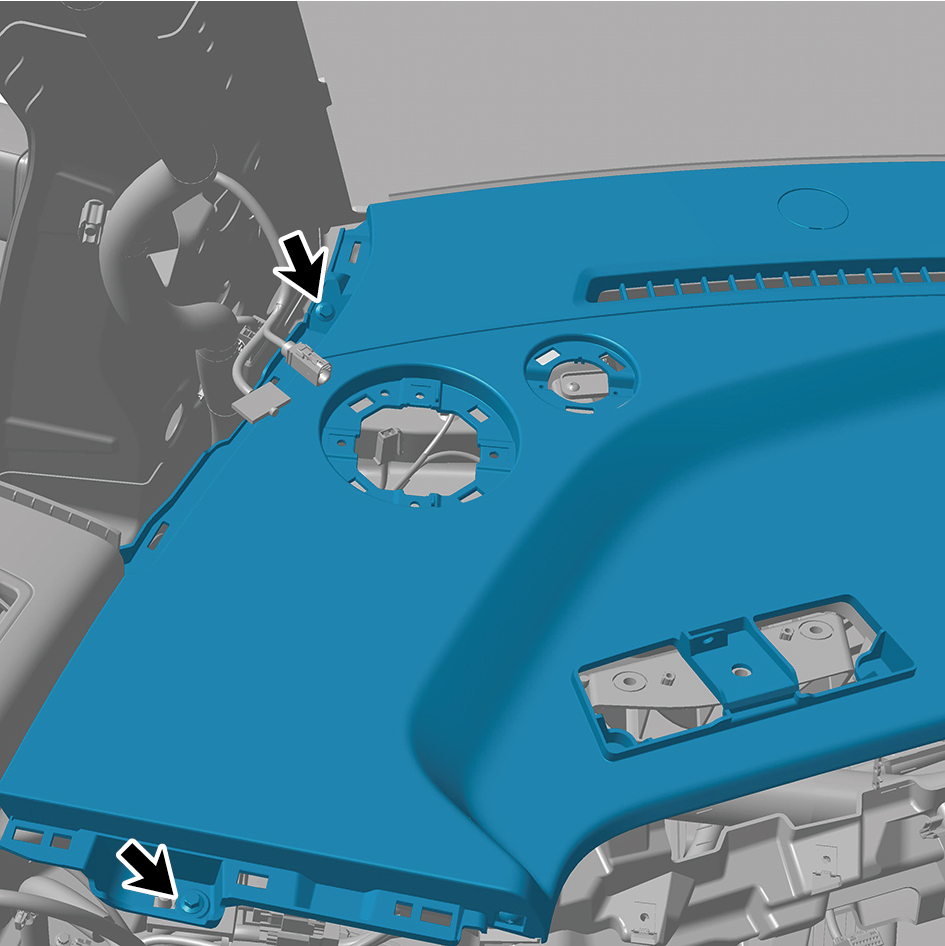
22
Remove 11 fixing screws of the IP upper body assembly.
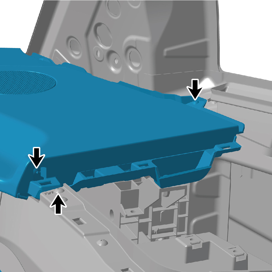
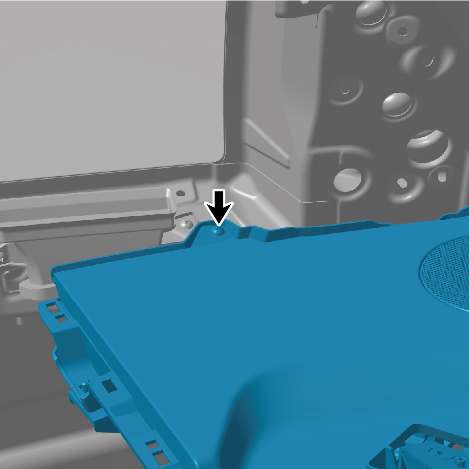
23
Detach 3 protection covers of the IP upper body assembly.
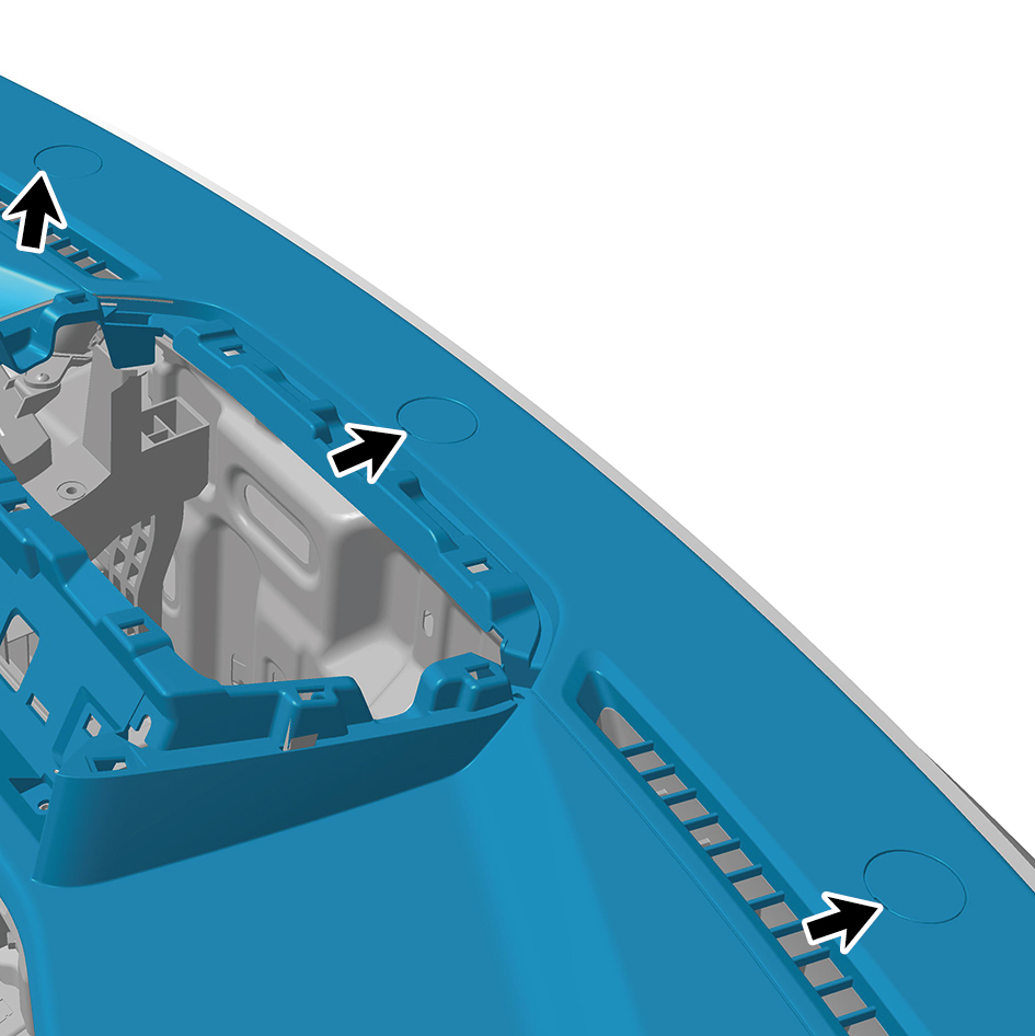
24
Remove 3 fixing bolts of the IP upper body assembly.
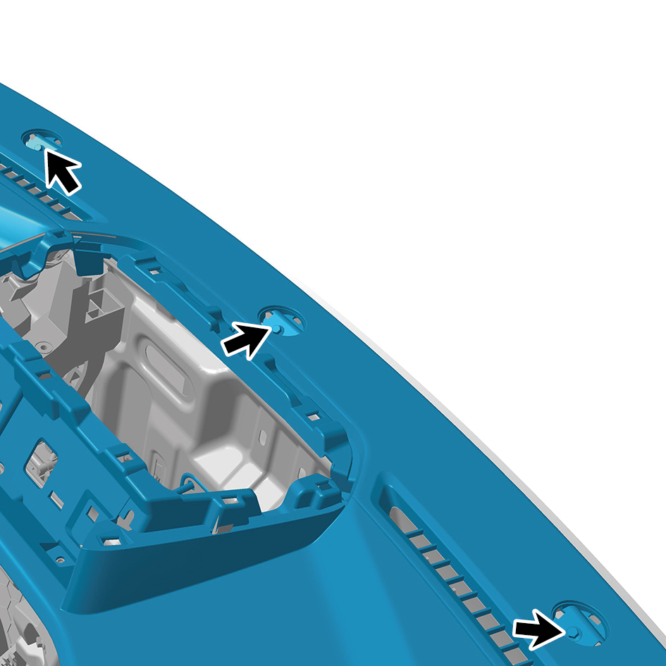
25
Remove the IP upper body assembly.
Installation Procedures
1
Move the IP upper body assembly to the mounting
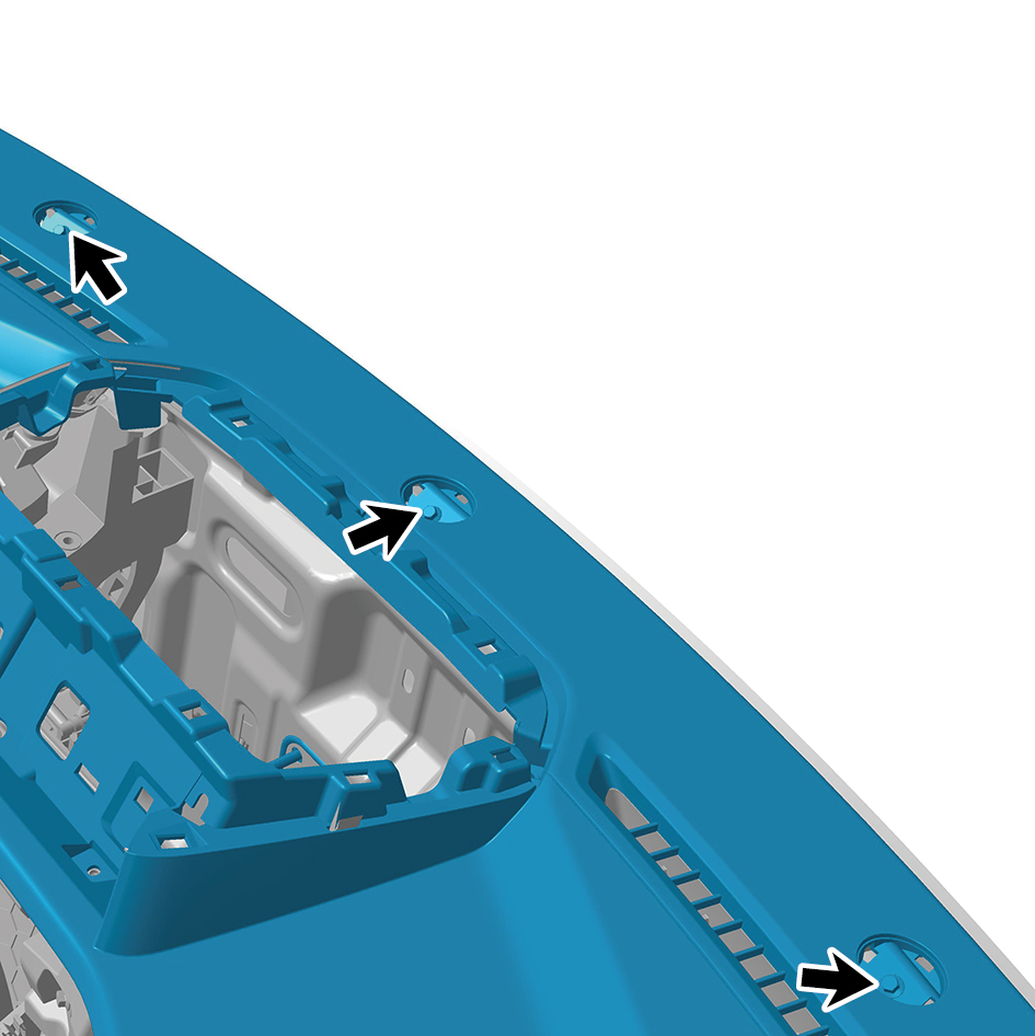
position.
2
Install 3 fixing bolts of the IP upper body assembly.
Torque:(6.5 +/- .75) ft lbs
3
Install 3 protection covers of the IP upper body assembly.
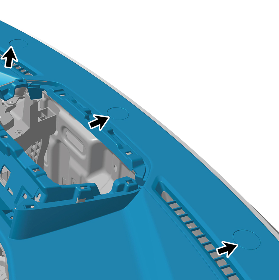
4
Install 11 fixing screws of the IP upper body assembly.
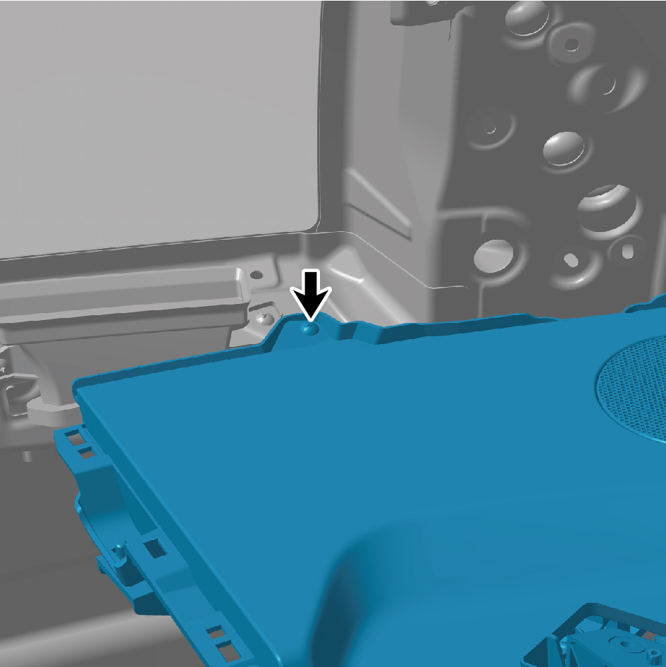
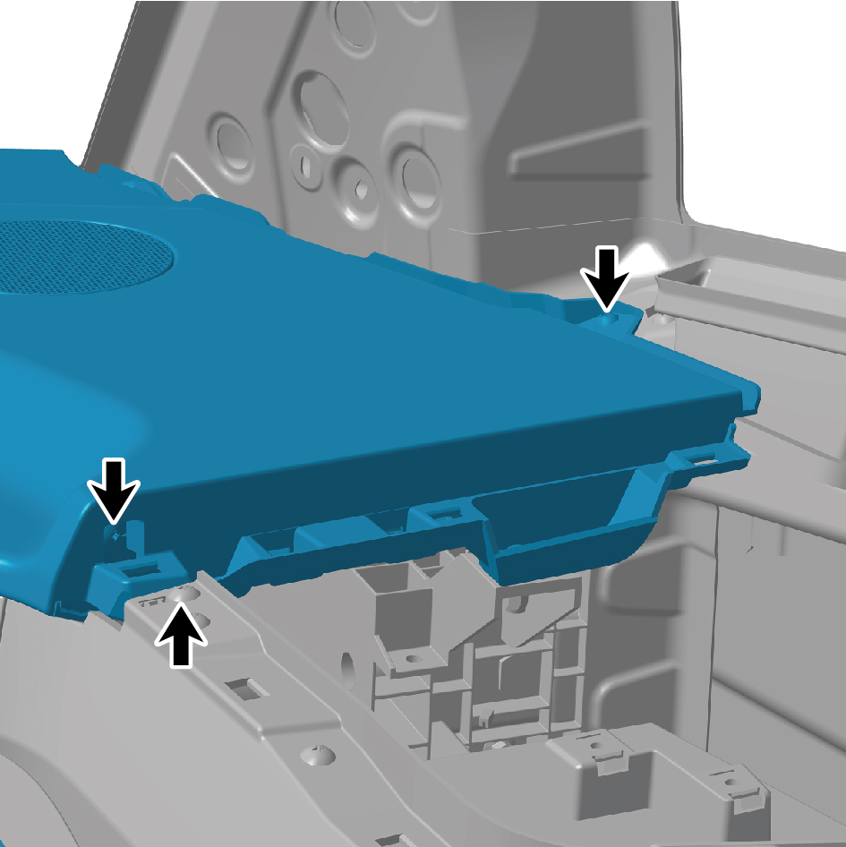
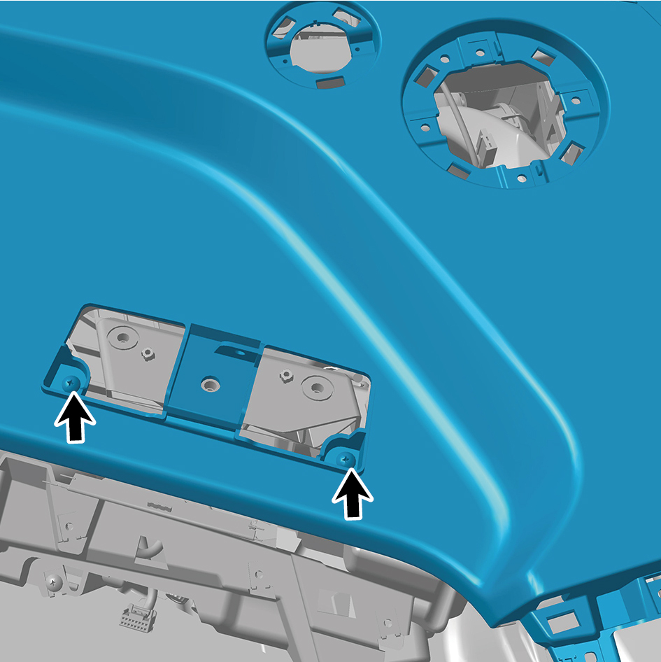
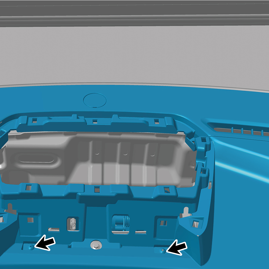
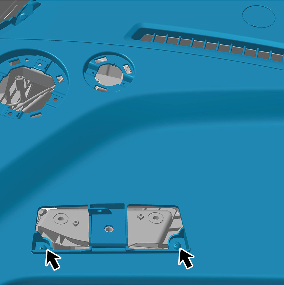
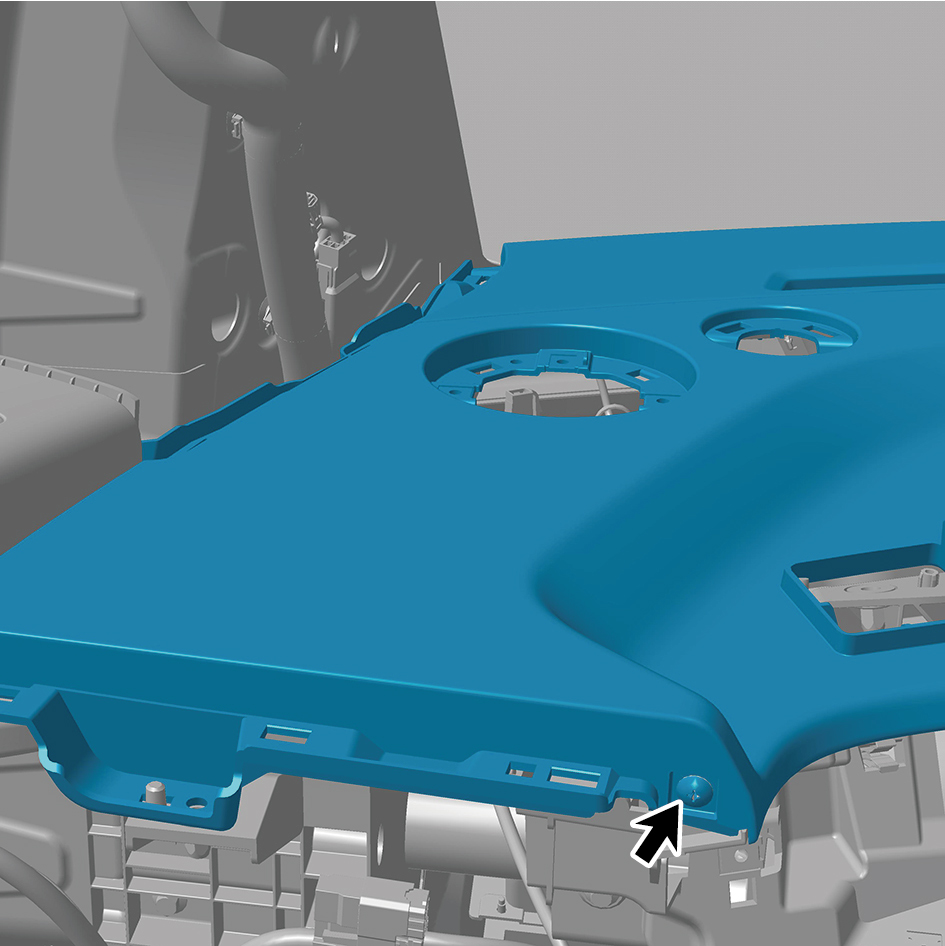
5
Install 4 fixing bolts of the IP upper body assembly.
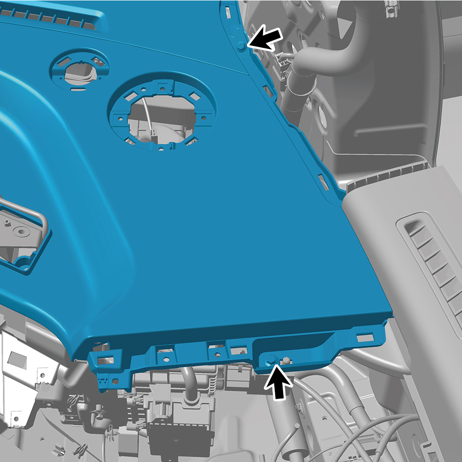
Torque:(6.5 +/- .75) ft lbs
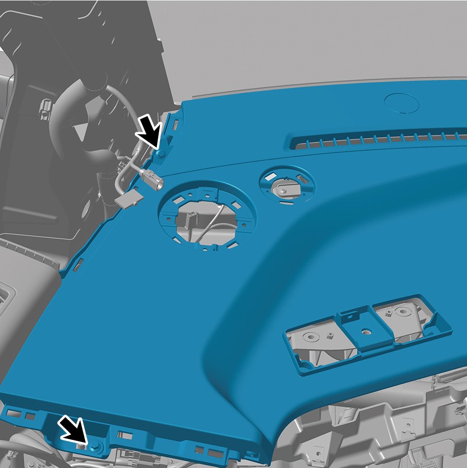
6
Install 2 fixing clips of the IP upper body assembly.
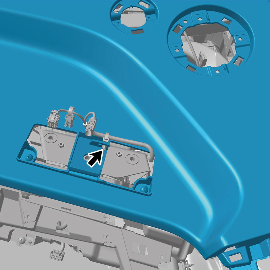
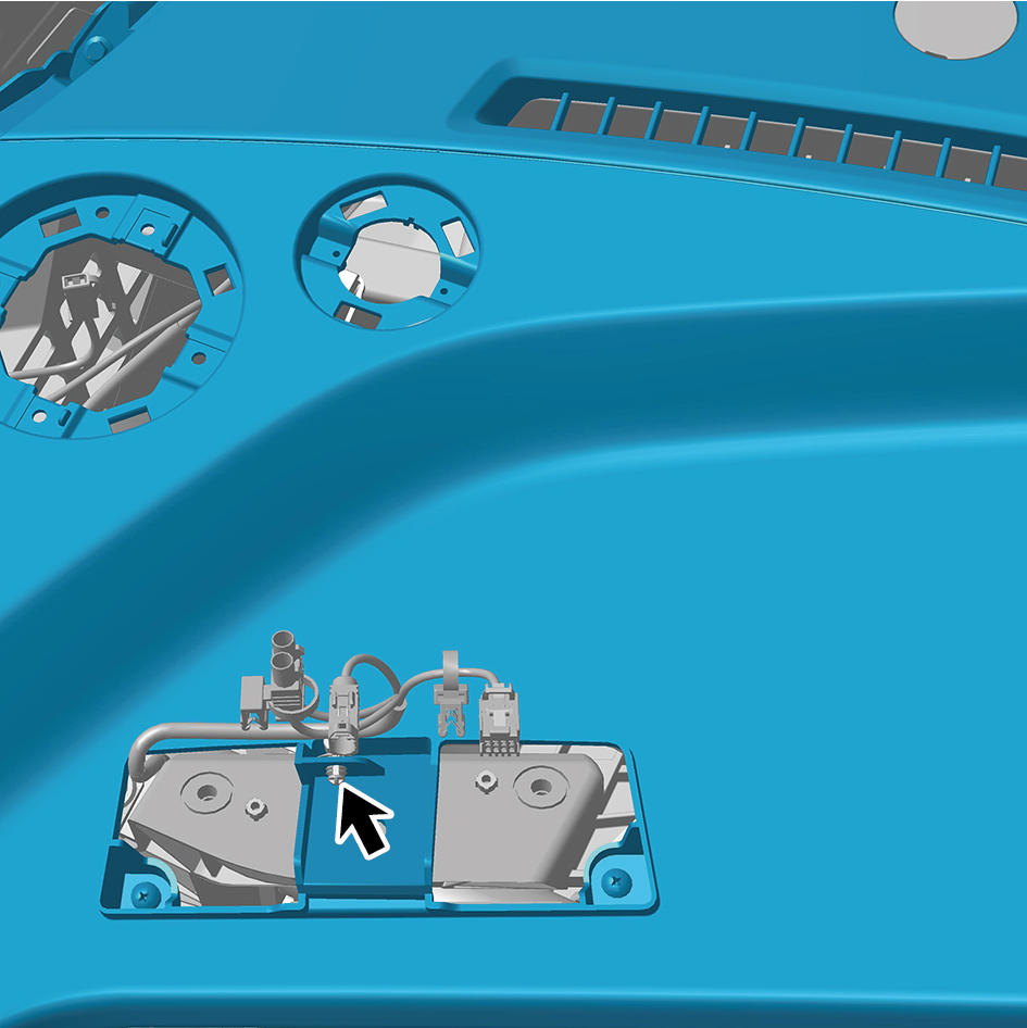
7
Install the front side enclosure assy-rh.
8
Install the assembly of the cover assy-steering under
column guard.
9
Install the front side enclosure assy-lh.
10
Install the assembly of the instrument panel trim panel
assy- lowerr lh.
11
Install the a-pillar guard assy-rh.
12
Install the a-pillar guard assy-lh.
13
Install the base-rh display brkt.
14
Install the camera monitor screen-rh.
15
Install the upr cover- rh camera brkt.
16
Install the base-lh display brkt.
17
Install the camera monitor screen.
18
Install the upr cover- lh camera brkt.
19
Install the ipc screen.
20
Install the car screen.
21
Install the ivi screen.
22
Install the ip brim assy.
23
Connect the battery negative cable.
24
Close the front flip cover plate.
25
Close the door.
6.11.3.7 Replacement of IP Brim Assembly
Removal Procedures
1
Open the door.
2
Remove the IP brim assembly.
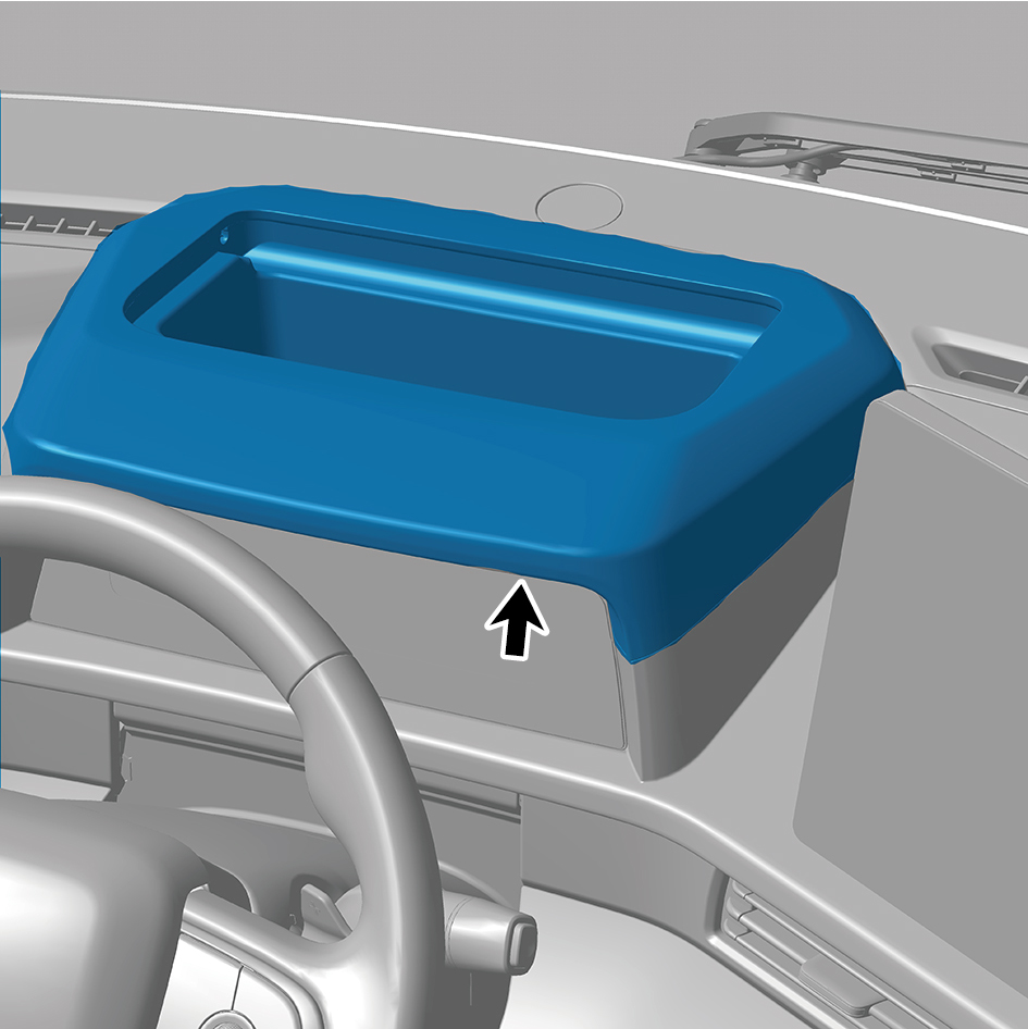
Installation Procedures
1
Install the IP brim assembly.
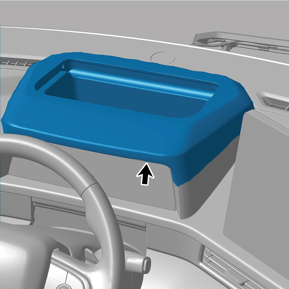
2
Close the door.
6.11.3.8 Replacement of Left Vent Trim Panel Assembly
Assembly
Removal Procedures
1
Open the door.
2
Open the front flip cover plate.
3
Disconnect the battery negative cable.
caution
power down the high-voltage system before
disconnecting the negative pole of the storage
battery.
4
Remove the upr cover assy-combination switch.
5
Remove the vehicle travelling data recorder.
6
Remove the assembly of the instrument panel trim panel
assy-lowerr lh.
7
Remove the cover assy-dashboard-lh frt.
8
Remove the trim assy on the switch panel-lh.
9
Remove the switch panel lower trim assy-lh.
10
Remove the instrument panel trim panel assy-upper lh.
11
Remove 5 fixing screws of the left vent trim panel
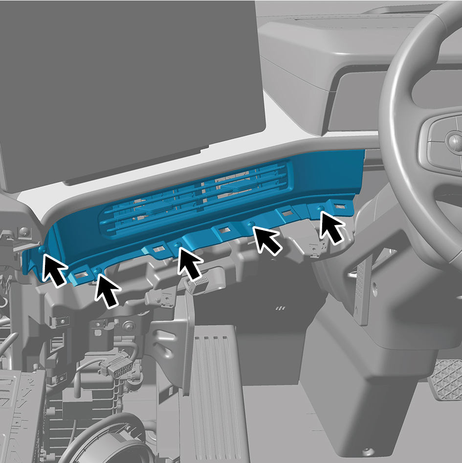
assembly.
12
Remove the left vent trim panel assembly.
Installation Procedures
1
Move the left vent trim panel assembly to the mounting
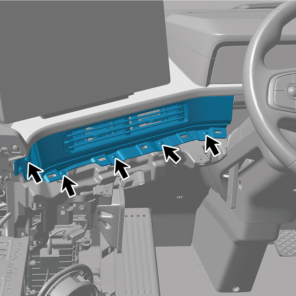
position.
2
Install 5 fixing screws of the left vent trim panel assembly.
3
Install the instrument panel trim panel assy-upper lh.
4
Install the switch panel lower trim assy-lh.
5
Install the trim assy on the switch panel-lh.
6
Install the cover assy-dashboard-lh frt.
7
Install the assembly of the instrument panel trim panel
assy-lowerr lh.
8
Install the vehicle travelling data recorder.
9
Install the upr cover assy-combination switch.
10
Connect the battery negative cable.
11
Close the front flip cover plate.
12
Close the door.
6.11.3.9 Replacement of Right Vent Trim Panel Assembly
Assembly
Removal Procedures
1
Open the door.
2
Open the front flip cover plate.
3
Disconnect the battery negative cable.
caution
power down the high-voltage system before
disconnecting the negative pole of the storage
battery.
4
Remove the upr cover assy-combination switch.
5
Remove the assembly of the cover assy-steering under
column guard.
6
Remove the cover assy-dashboard-rh frt.
7
Remove the switch panel assy-rh.
8
Remove the lower switch panel assy-rh.
9
Remove the storage box assy-rh.
10
Remove 5 fixing screws of the right vent trim panel
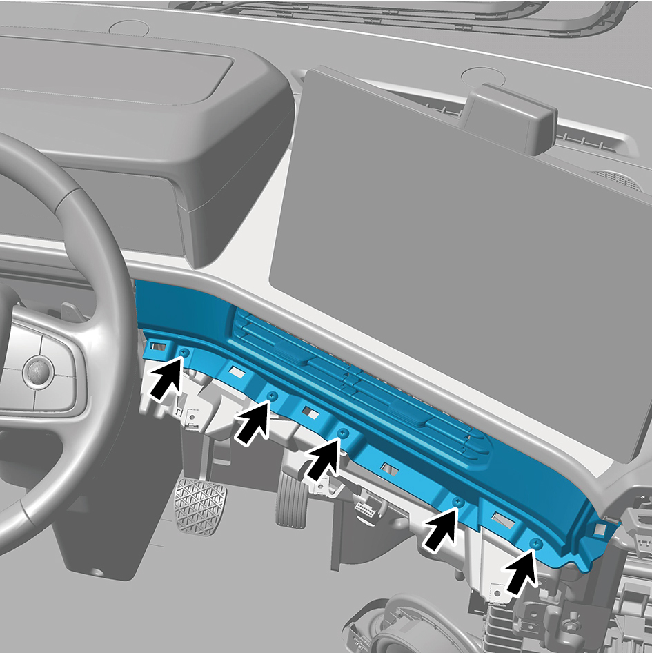
assembly.
11
Remove the right vent trim panel assembly.
Installation Procedures
1
Move the right vent trim panel assembly to the mounting
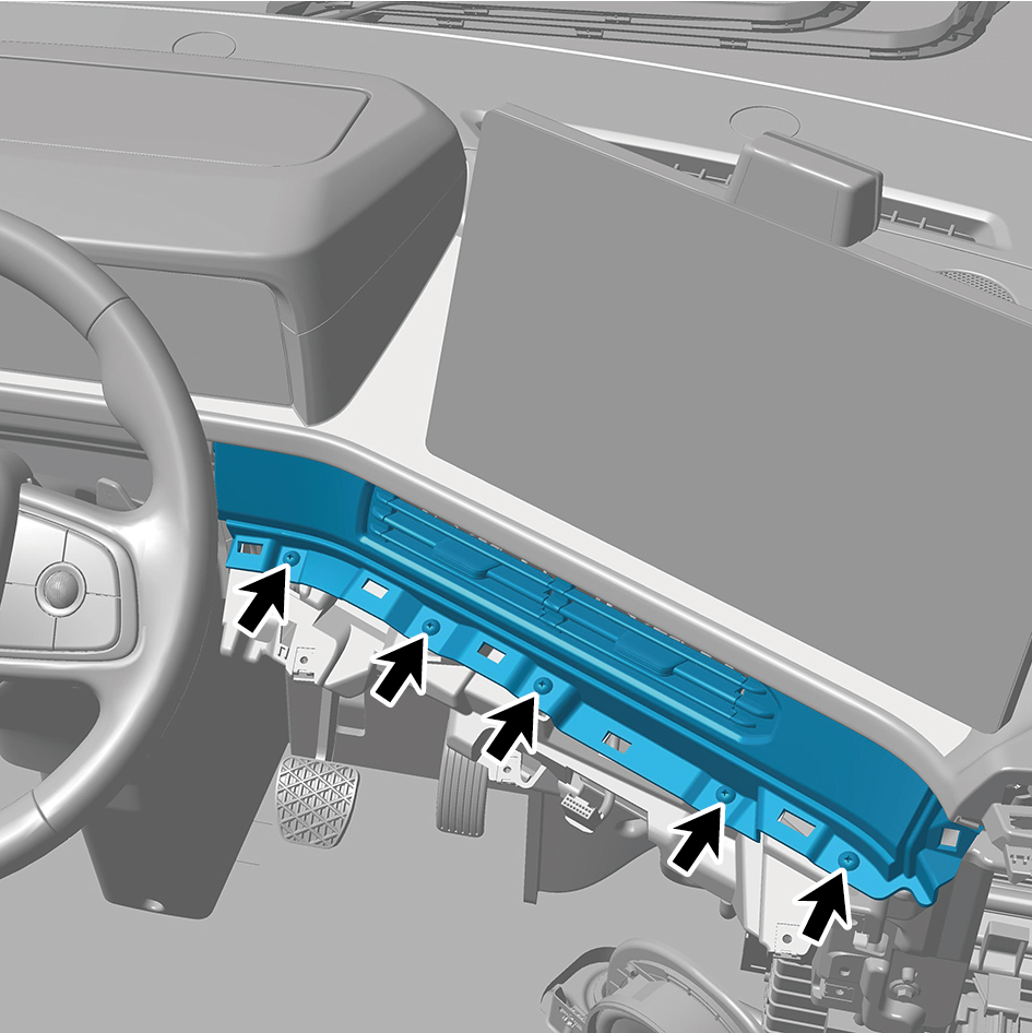
position.
2
Install 5 fixing screws of the right vent trim panel
assembly.
3
Install the storage box assy-rh.
4
Install the lower switch panel assy-rh.
5
Install the switch panel assy-rh.
6
Install the cover assy-dashboard-rh frt.
7
Install the Assembly of the cover assy-steering under
column guard.
8
Install the upr cover assy-combination switch.
9
Connect the battery negative cable.
10
Close the front flip cover plate.
11
Close the door.
6.11.3.10 Replacement of Left Foot Blowing Duct Assembly
Duct Assembly
Removal Procedures
1
Open the door.
2
Remove the IP left access cover plate assembly.
3
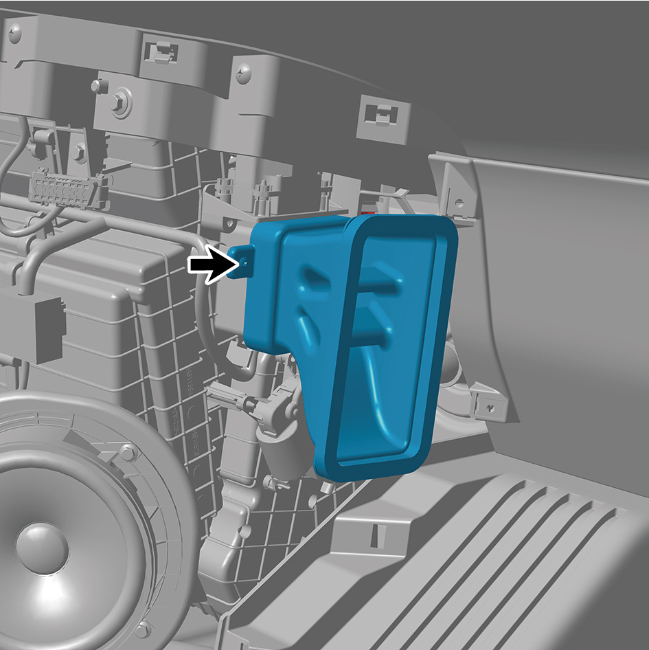
Remove 2 fixing screws of the left foot blowing duct
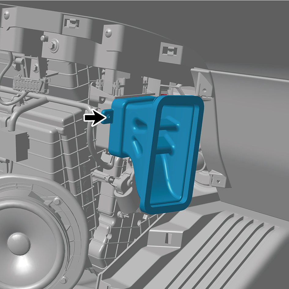
assembly, and remove the left foot blowing duct assembly.
Installation Procedures
1
Move the left foot blowing duct assembly to the mounting
position.
2
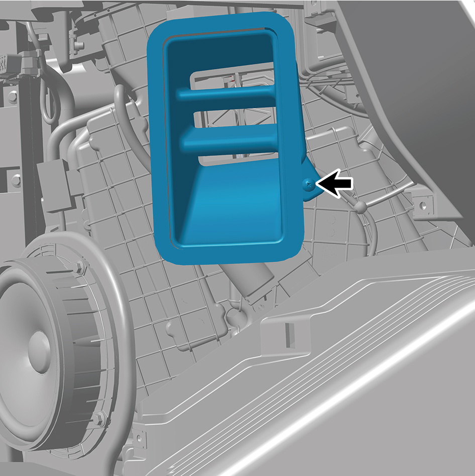
Install 2 fixing screws of the left foot blowing duct
assembly.
3
Install the IP left access cover plate assembly.
4
Close the door.
6.11.3.11 Replacement of Right Foot Blowing Duct Assembly
Duct Assembly
Removal Procedures
1
Open the door.
2
Remove the IP right access cover plate assembly.
3
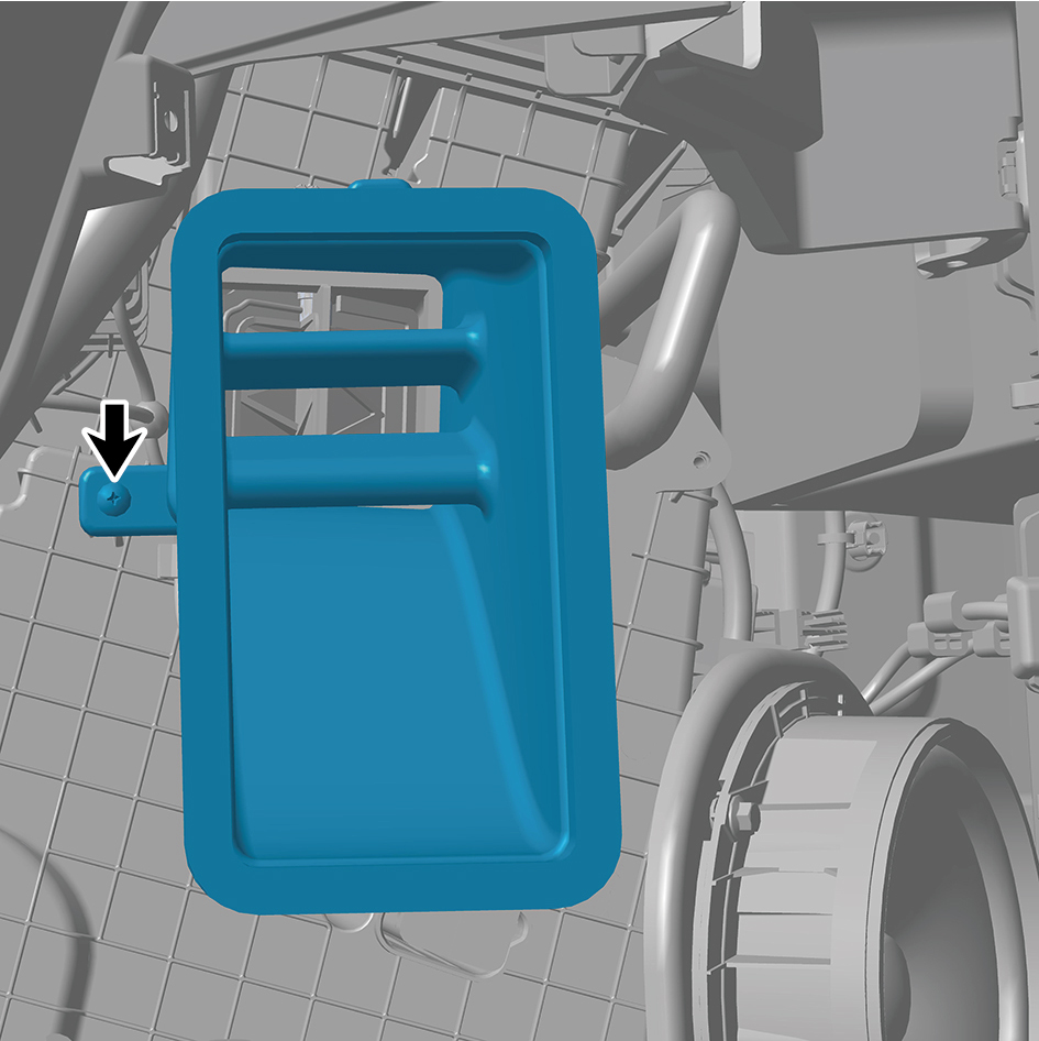
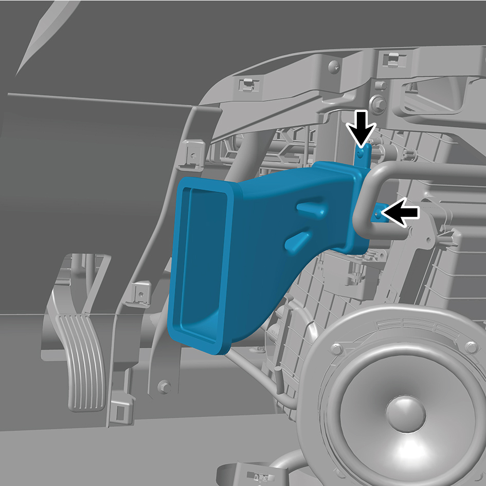
Remove 3 fixing screws of the right foot blowing duct
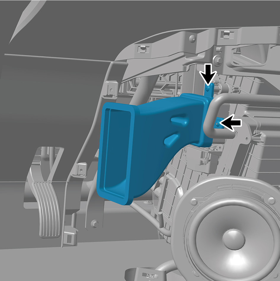
assembly, and remove the right foot blowing duct
assembly.
Installation Procedures
1
Move the right foot blowing duct assembly to the mounting
position.
2
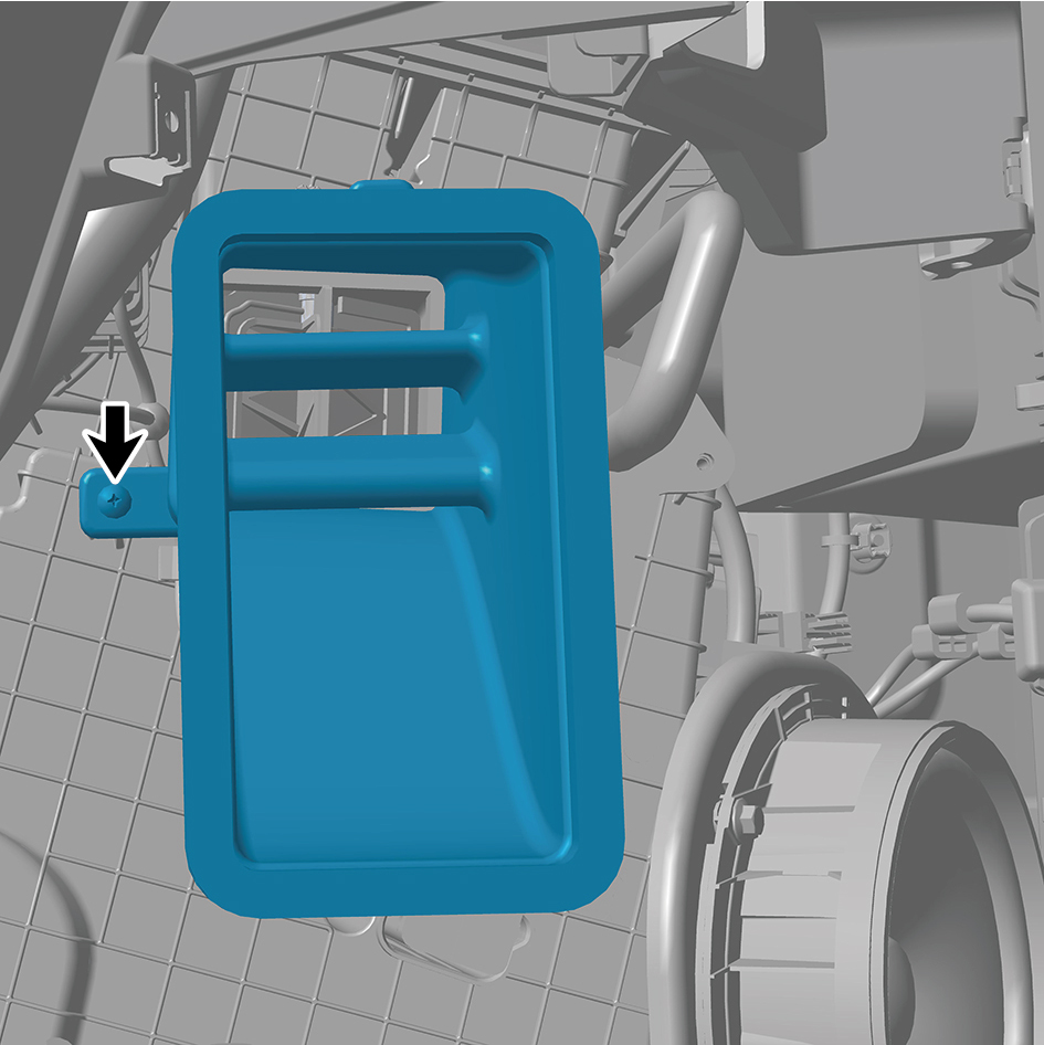
Install 3 fixing screws of the right foot blowing duct
assembly.
3
Install the IP right access cover plate assembly.
4
Close the door.
6.11.3.12 Replacement of IP Left Lower Trim Panel Assembly
Panel Assembly
Removal Procedures
1
Open the door.
2
Open the front flip cover plate.
3
Disconnect the battery negative cable.
caution
power down the high-voltage system before
disconnecting the negative pole of the storage
battery.
4
Remove the assembly of the instrument panel trim panel
assy- lowerr lh.
5
Remove the vehicle travelling data recorder.
6
Remove the cover assy-dashboard-lh frt.
7
Remove the trim assy on the switch panel-lh.
8
Remove the switch panel lower trim assy-lh.
9
Use a small flat-head screwdriver to pry open the cover
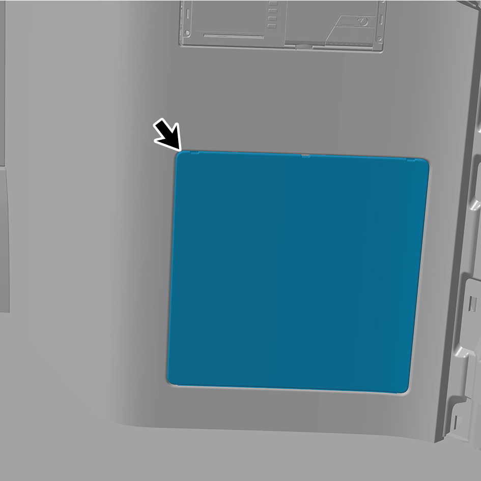
plate from the three notches at the top.Separate the upper
clips.Insert a long - handled clip prying plate into the area
where the cover has been pried open. Pry open the clips
beneath the cover, and then remove the cover.
caution
The width of the flat - bladed screwdriver should be
smaller than that of the notches on the cover.
Otherwise, it may scratch the cover, and in severe
cases, even damage it.
Before using the flat - bladed screwdriver, wrap the
flat tip with cloth tape or a strip of cloth to prevent
scratching the cover.
10
Remove 3 fixing screws of the IP left lower trim panel
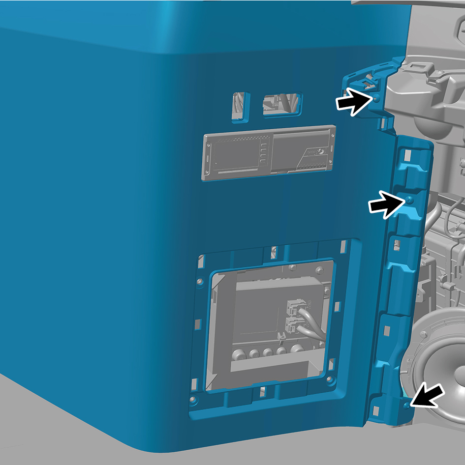
assembly.
11
Remove 3 fixing bolts of the IP left lower trim panel
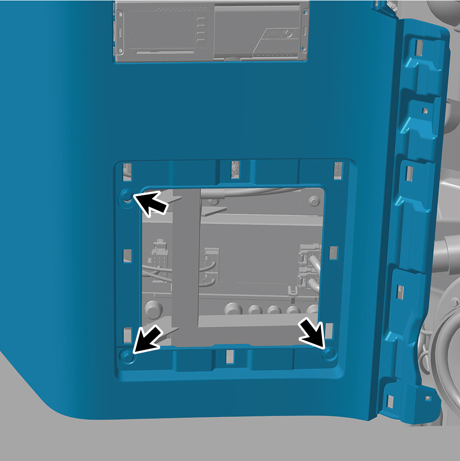
assembly.
12
Remove the IP left lower trim panel assembly.
Installation Procedures
1
Move the IP left lower trim panel assembly to the
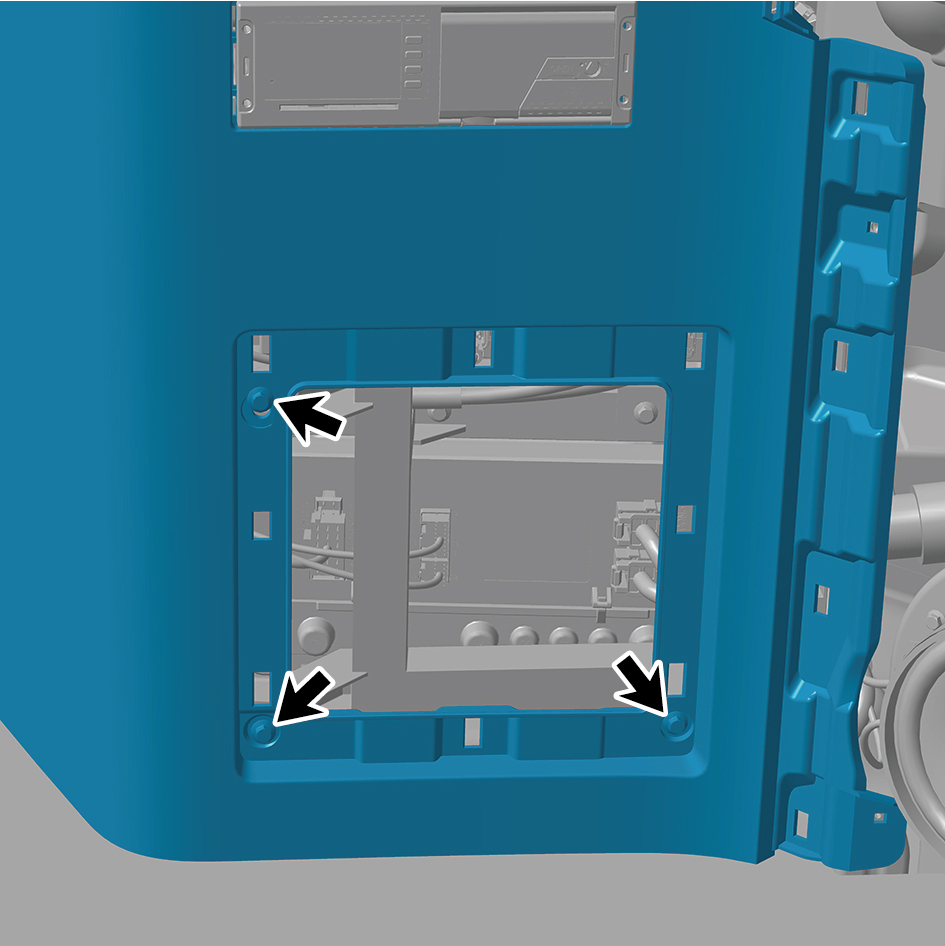
mounting position.
2
Install 3 fixing bolts of the IP left lower trim panel
assembly.
Torque: (6.5 ft-lb +/- .75 ft-lb) ft-lb
3
Install 3 fixing screws of the IP left lower trim panel
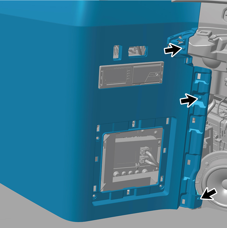
assembly.
4
Install the cover plate.
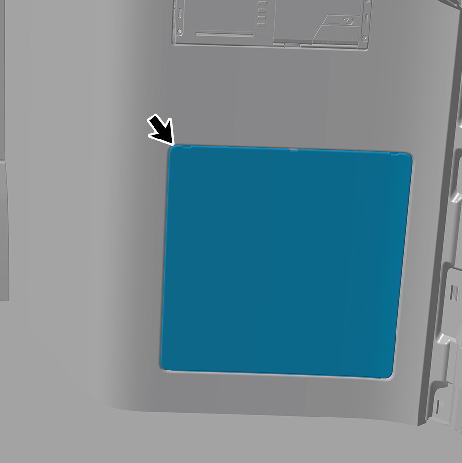
5
Install the switch panel lower trim assy-lh.
6
Install the trim assy on the switch panel-lh.
7
Install the cover assy-dashboard-lh frt.
8
Install the vehicle travelling data recorder.
9
Install the assembly of the instrument panel trim panel
assy- lowerr lh.
10
Connect the battery negative cable.
11
Close the front flip cover plate.
12
Close the door.
6.11.3.13 Replacement of Right Storage Box Assembly
Assembly
Removal Procedures
1
Open the door.
2
Open the front flip cover plate.
3
Disconnect the battery negative cable.
caution
power down the high-voltage system before
disconnecting the negative pole of the storage
battery.
4
Remove the IP right upper trim panel assembly.
5
Remove the IP right access cover plate assembly.
6
Remove the right switch panel assembly.
7
Remove the right switch panel lower trim panel assembly.
8
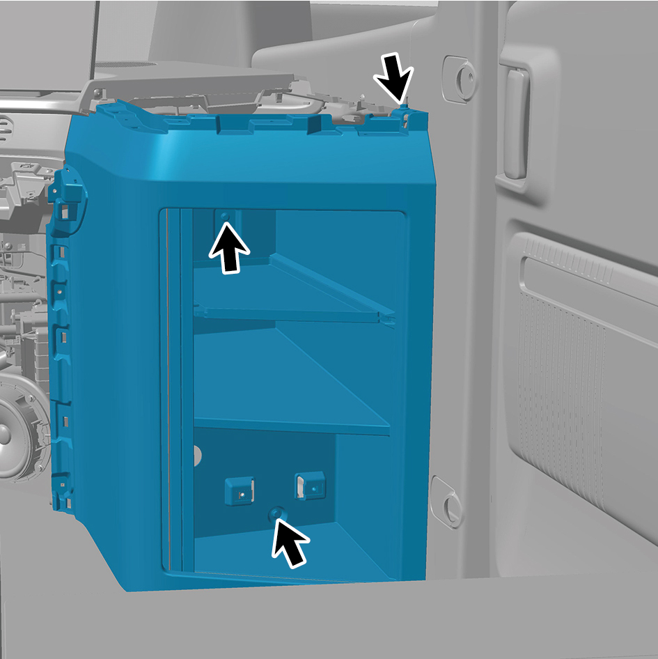
Remove 4 fixing screws of the right storage box assembly.
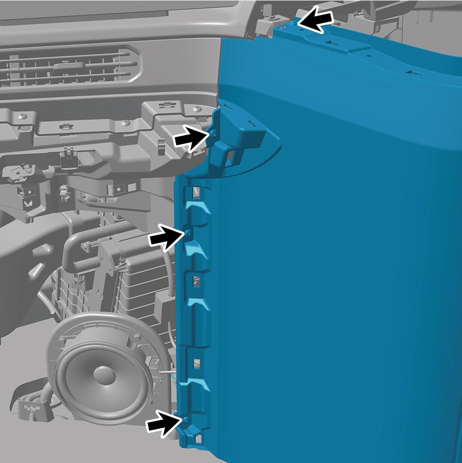
9
Remove 3 fixing bolts of the right storage box assembly.
10
Remove the right storage box assembly.
Installation Procedures
1
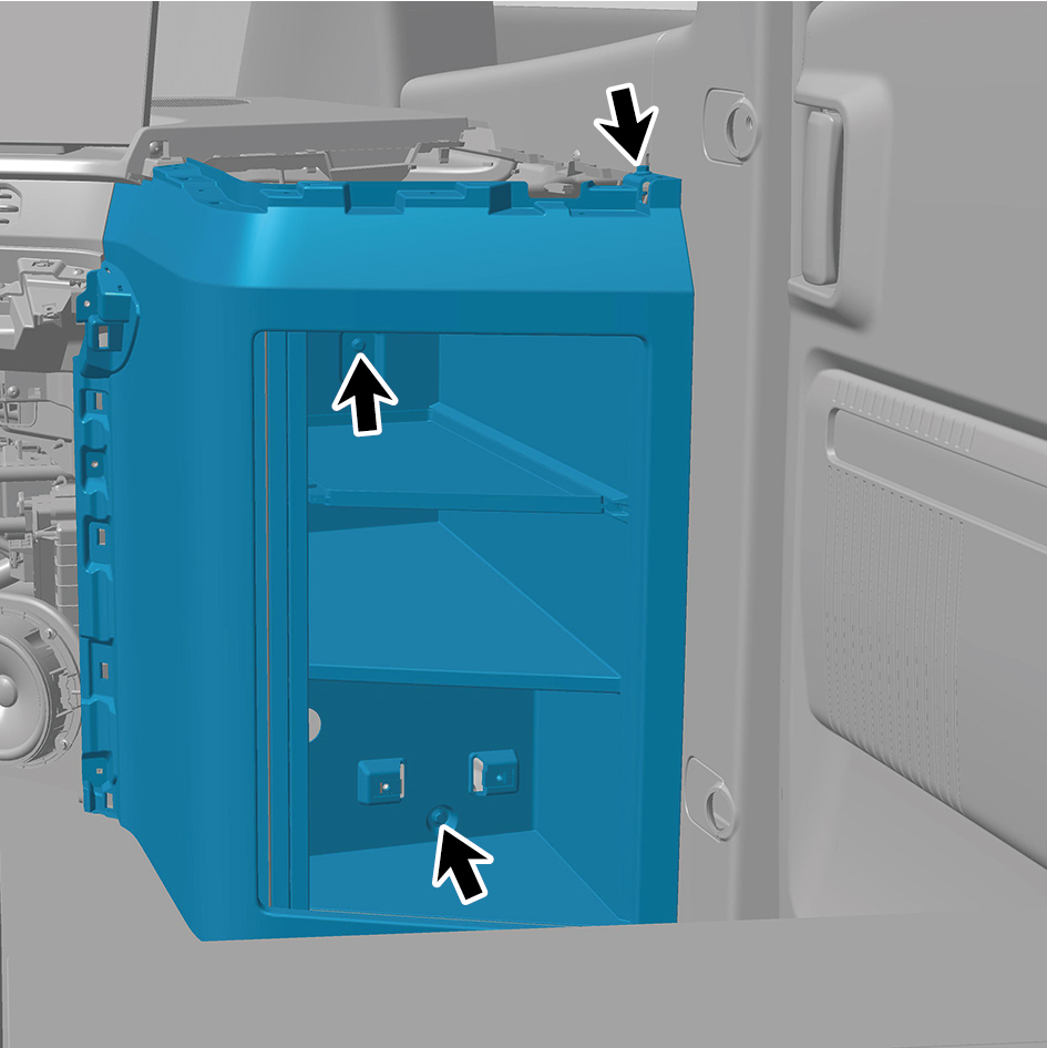
Move the right storage box assembly to the mounting
position.
2
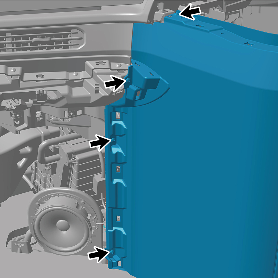
Install 3 fixing bolts of the right storage box assembly.
Torque: (6.5 +/- .75) ft lbs
3
Install 4 fixing screws of the right storage box assembly.
4
Install the right switch panel lower trim panel assembly.
5
Install the right switch panel assembly.
6
Install the IP right access cover plate assembly.
7
Install the IP right upper trim panel assembly.
8
Connect the battery negative cable.
9
Close the front flip cover plate.
10
Close the door.
6.11.3.14 Replacement of IP Left Upper Trim Panel Assembly
Panel Assembly
Removal Procedures
1
Open the door.
2
Open the front flip cover plate.
3
Disconnect the battery negative cable.
caution
power down the high-voltage system before
disconnecting the negative pole of the storage
battery.
4
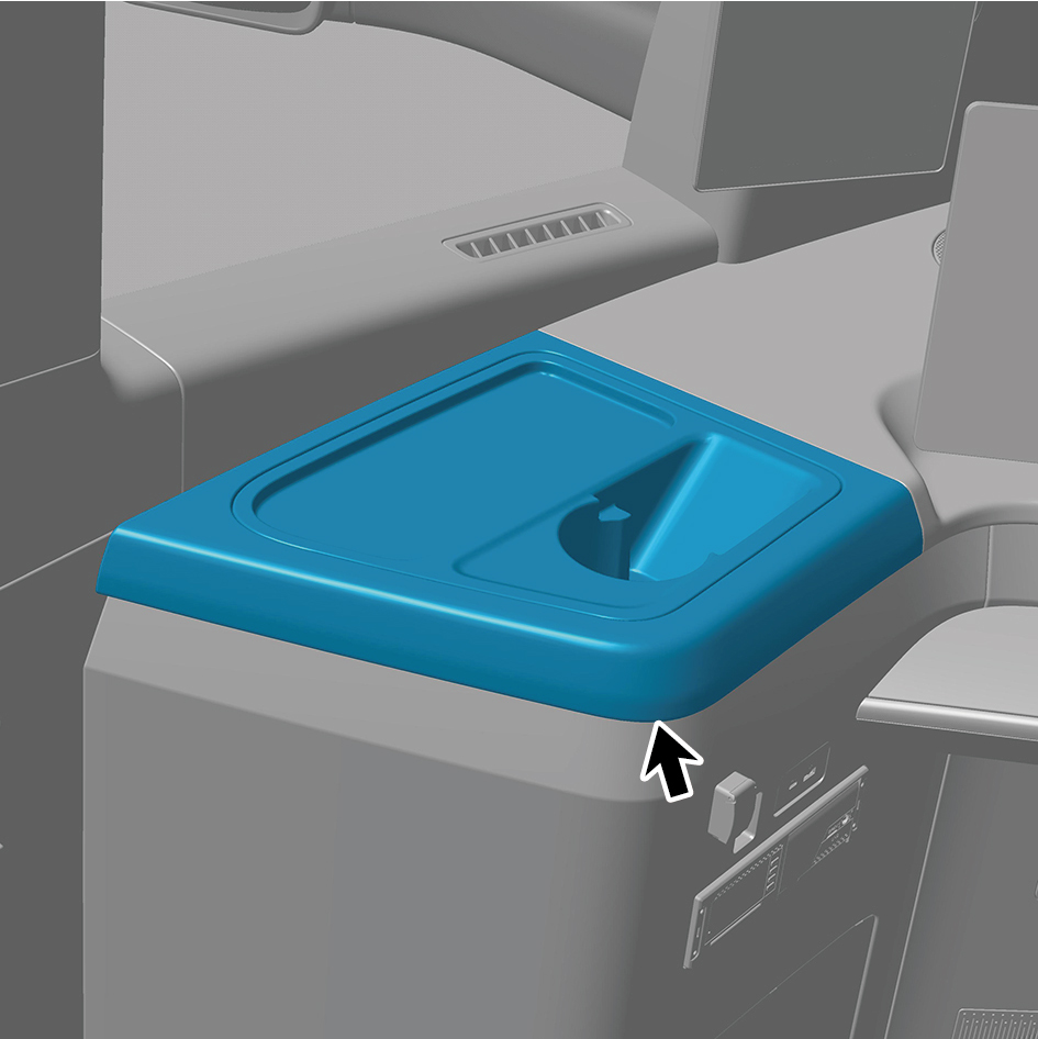
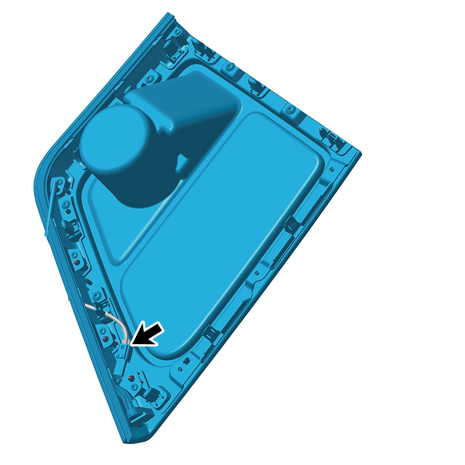
Detach the IP left upper trim panel assembly.
5
Disconnect 1 harness connector of the IP left upper trim
panel assembly.
6
Remove the IP left upper trim panel assembly.
Installation Procedures
1
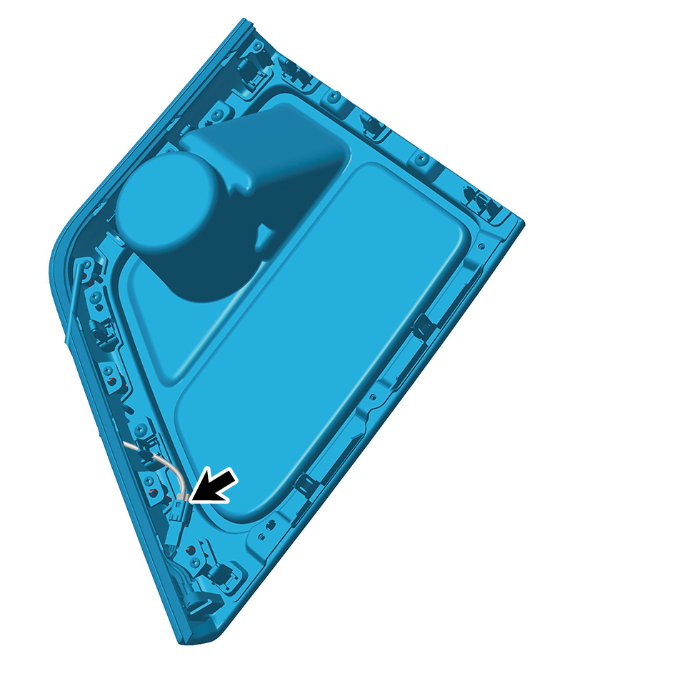
Move the IP left upper trim panel assembly to the
mounting position.
2
Connect 1 harness connector of the IP left upper trim
panel assembly.
caution
The harness is firmly connected following the
principal of "insert until a click is heard for
confirmation".
3
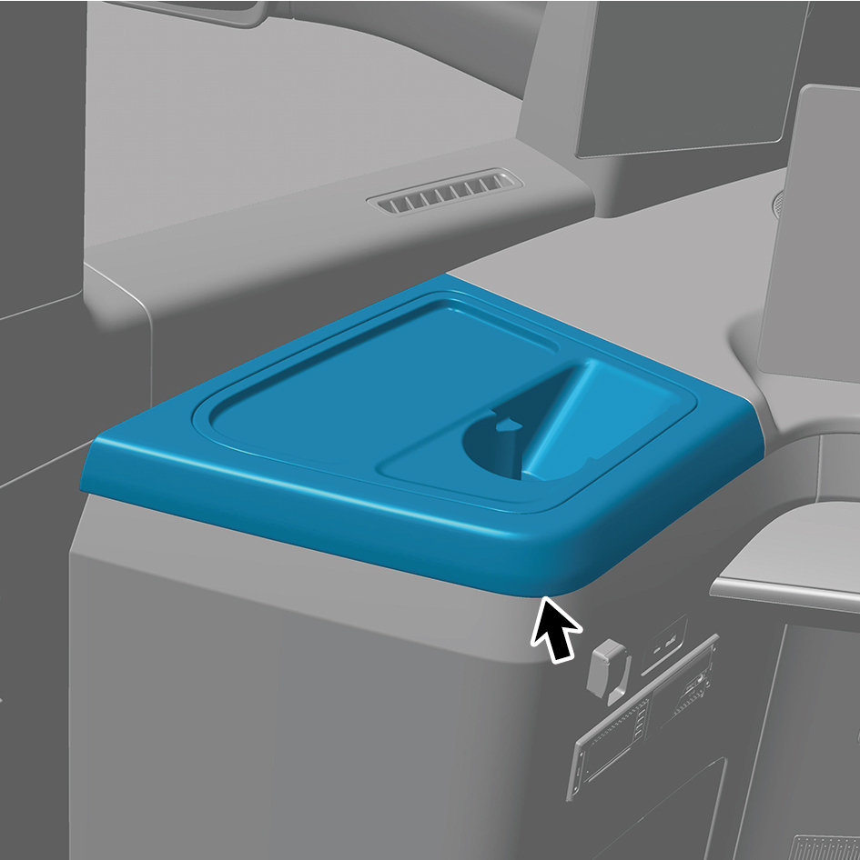
Install the IP left upper trim panel assembly.
4
Connect the battery negative cable.
5
Close the front flip cover plate.
6
Close the door.
6.11.3.15 Replacement of IP Right Upper Trim Panel Assembly
Panel Assembly
Removal Procedures
1
Open the door.
2
Open the front flip cover plate.
3
Disconnect the battery negative cable.
caution
power down the high-voltage system before
disconnecting the negative pole of the storage
battery.
4
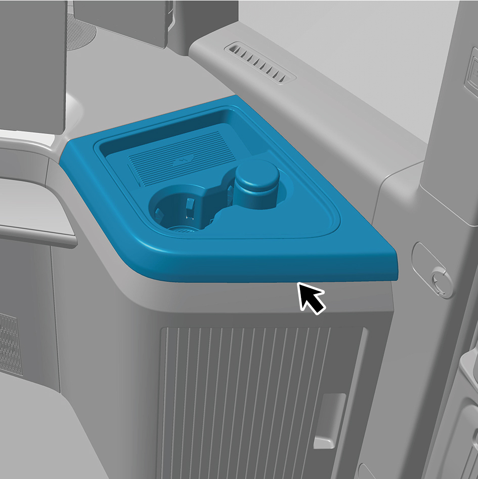
Detach the IP right upper trim panel assembly.
5
Disconnect 2 harness connectors of the IP right upper
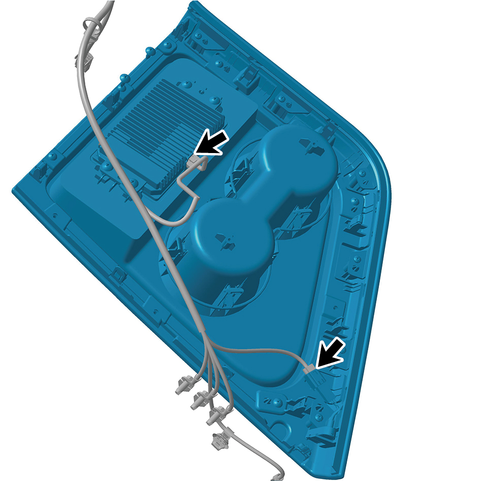
trim panel assembly.
6
Remove the IP right upper trim panel assembly.
Installation Procedures
1
Move the IP right upper trim panel assembly to the
mounting position.
2
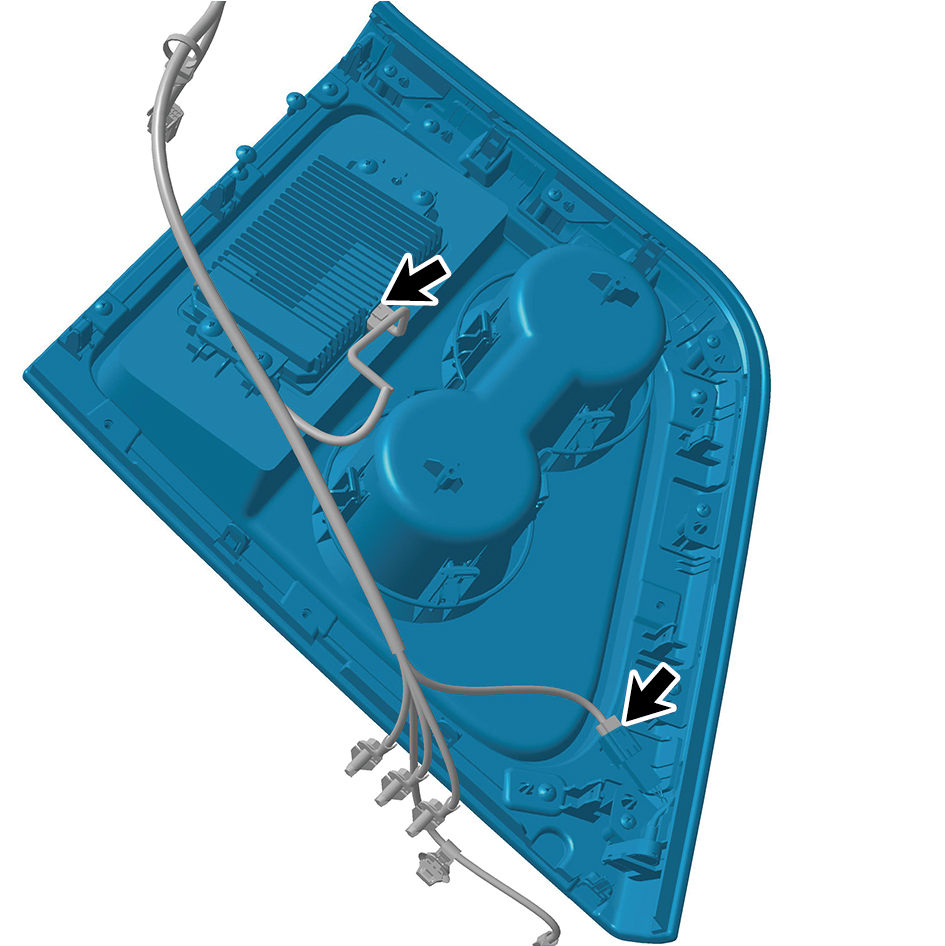
Connect 2 harness connectors of the IP right upper trim
panel assembly.
caution
The harness is firmly connected following the
principal of "insert until a click is heard for
confirmation".
3
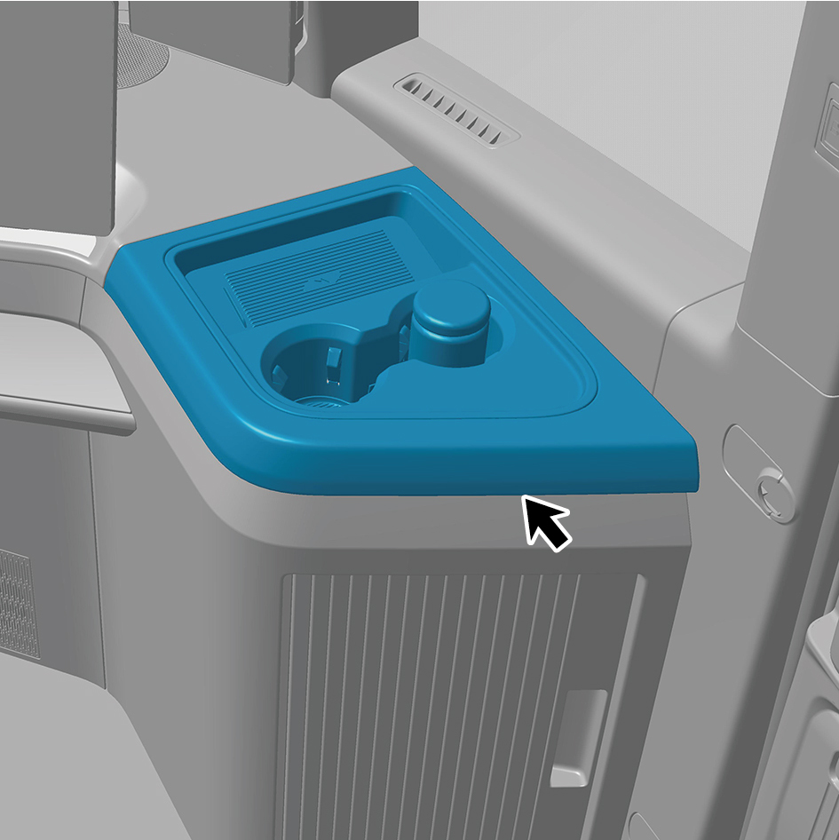
Install the IP right upper trim panel assembly.
4
Connect the battery negative cable.
5
Close the front flip cover plate.
6
Close the door.
6.11.3.16 Replacement of Steering Column Lower Shield Assembly
Lower Shield Assembly
Removal Procedures
1
Open the door.
2
Open the front flip cover plate.
3
Disconnect the battery negative cable.
caution
power down the high-voltage system before
disconnecting the negative pole of the storage
battery.
4
Remove the IP left access cover plate assembly.
5
Remove the left switch panel assembly.
6
Remove the left switch panel lower trim panel assembly.
7
Remove the IP left front trim panel assembly.
8
Remove the IP right access cover plate assembly.
9
Remove the right switch panel assembly.
10
Remove the right switch panel lower trim panel assembly.
11
Remove the IP right front lower trim panel assembly.
12
Remove the IP right front upper trim panel assembly.
13
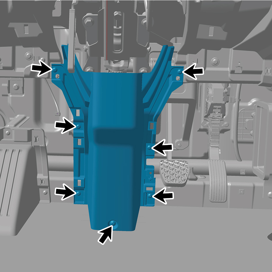
Remove 7 fixing screws of the steering column lower
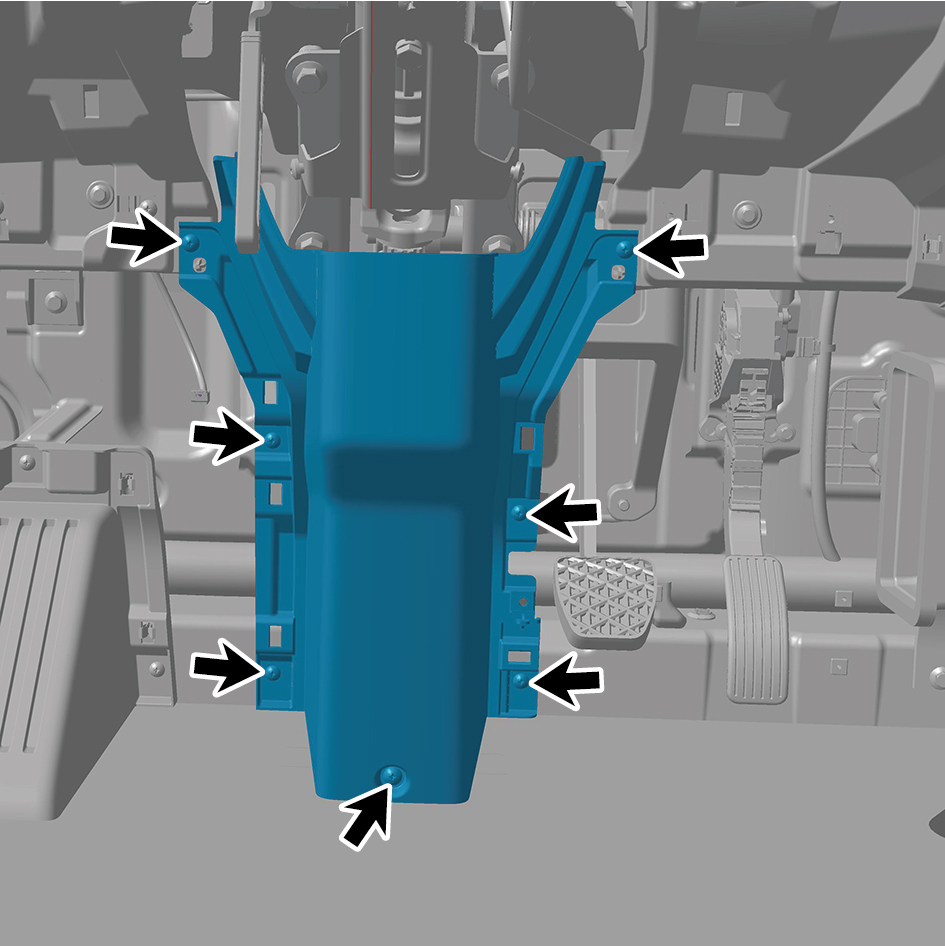
shield assembly.
14
Remove the steering column lower shield assembly.
Installation Procedures
1
Move the steering column lower shield assembly to the
mounting position.
2
Install 7 fixing screws of the steering column lower shield
assembly.
3
Install the IP right front upper trim panel assembly.
4
Install the IP right front lower trim panel assembly.
5
Install the right switch panel lower trim panel assembly.
6
Install the right switch panel assembly.
7
Install the IP right access cover plate assembly.
8
Install the IP left front trim panel assembly.
9
Install the left switch panel lower trim panel assembly.
10
Install the left switch panel assembly.
11
Install the IP left access cover plate assembly.
12
Connect the battery negative cable.
13
Close the front flip cover plate.
14
Close the door.
6.11.3.17 Replacement of Footrest Assembly
Removal Procedures
1
Open the door.
2
Open the front flip cover plate.
3
Disconnect the battery negative cable.
caution
power down the high-voltage system before
disconnecting the negative pole of the storage
battery.
4
Remove the IP left access cover plate assembly.
5
Remove the left switch panel assembly.
6
Remove the left switch panel lower trim panel assembly.
7
Remove the IP left front trim panel assembly.
8
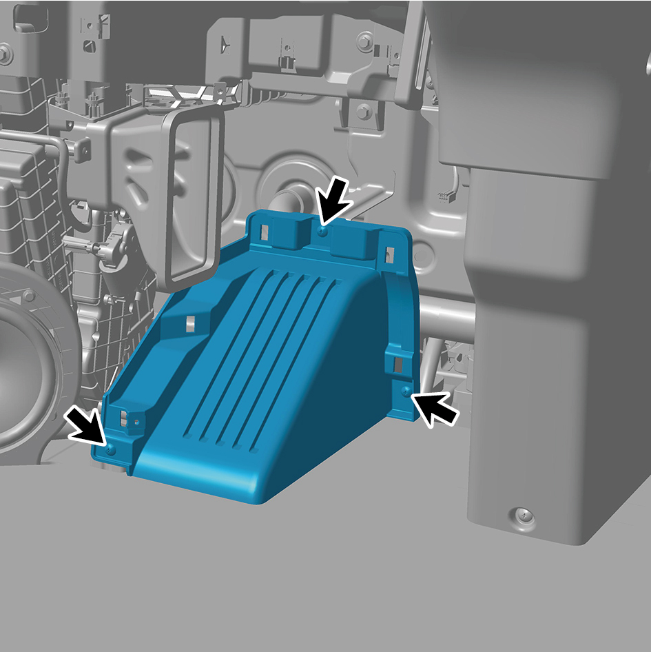
Remove 3 fixing screws of the footrest assembly.
9
Remove the footrest assembly.
Installation Procedures
1
Move the footrest assembly to the mounting position.
2
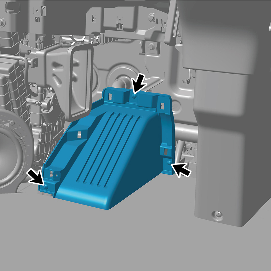
Install 3 fixing screws of the footrest assembly.
3
Install the IP left front trim panel assembly.
4
Install the left switch panel lower trim panel assembly.
5
Install the left switch panel assembly.
6
Install the IP left access cover plate assembly.
7
Connect the battery negative cable.
8
Close the front flip cover plate.
9
Close the door.
6.11.3.18 Replacement of IP Left Front Trim Panel Assembly
Panel Assembly
Removal Procedures
1
Open the door.
2
Open the front flip cover plate.
3
Disconnect the battery negative cable.
caution
power down the high-voltage system before
disconnecting the negative pole of the storage
battery.
4
Remove the IP left access cover plate assembly.
5
Remove the left switch panel assembly.
6
Remove the left switch panel lower trim panel assembly.
7
Remove 2 fixing screws of the IP left front trim panel
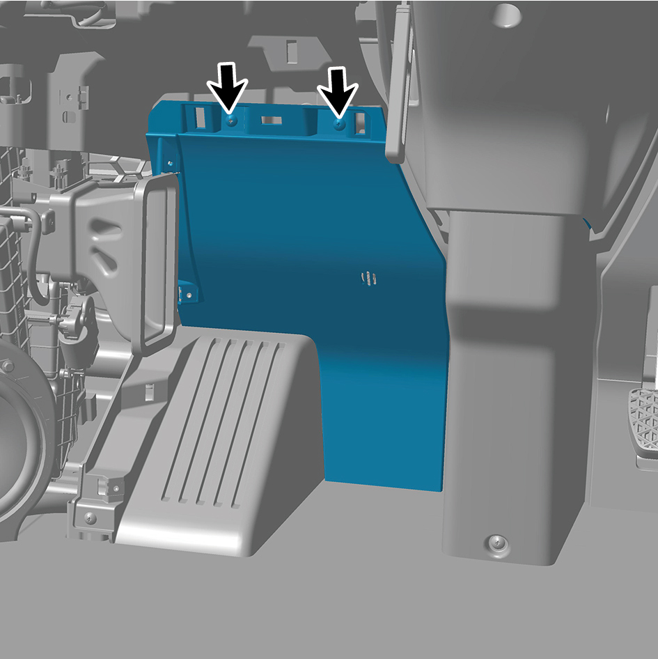
assembly.
8
Detach the IP left front trim panel assembly.
9
Disconnect 1 harness connector of the IP left front trim
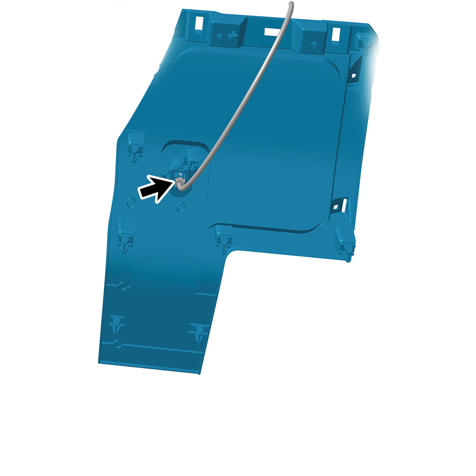
panel assembly.
Installation Procedures
1
Move the IP left front trim panel assembly to the mounting
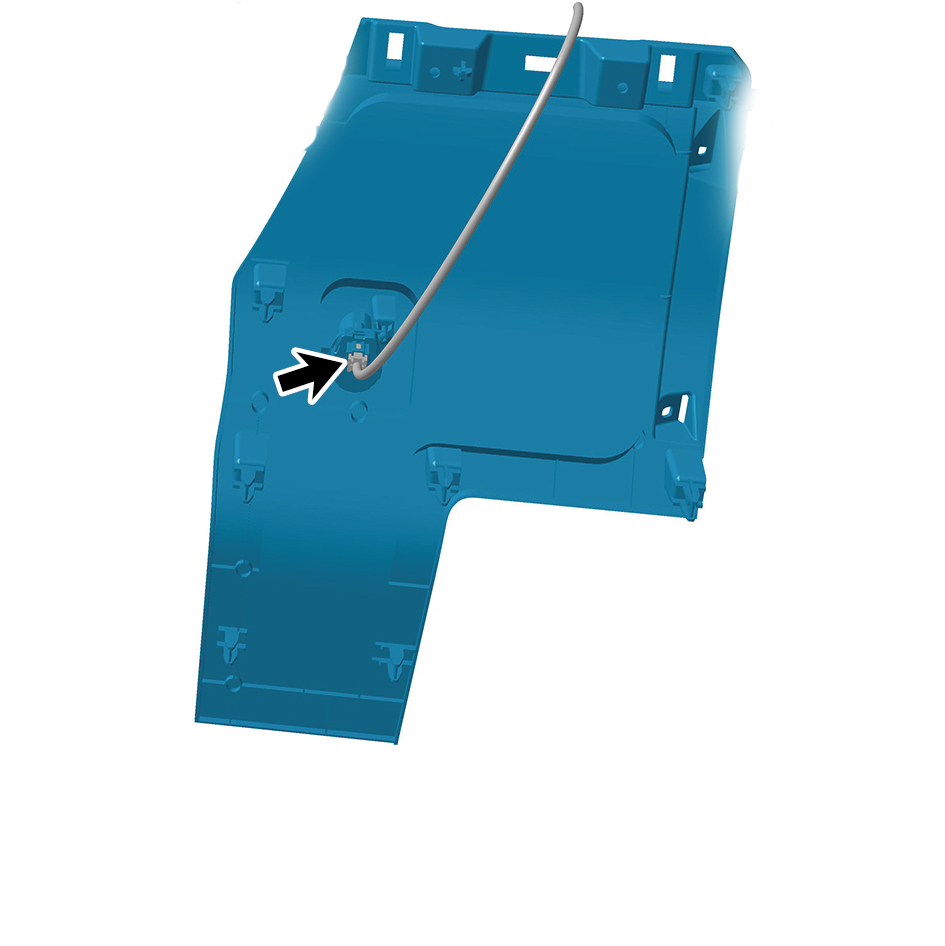
position.
2
Connect 1 harness connector of the interior temperature
sensor assembly.
caution
The harness is firmly connected following the
principal of "insert until a click is heard for
confirmation".
3
Install 2 fixing screws of the IP left front trim panel
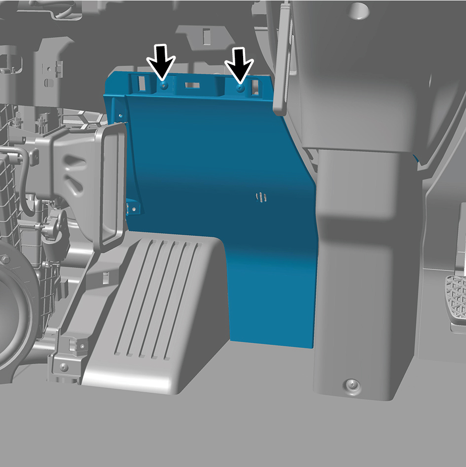
assembly.
4
Install the left switch panel lower trim panel assembly.
5
Install the left switch panel assembly.
6
Install the IP left access cover plate assembly.
7
Connect the battery negative cable.
8
Close the front flip cover plate.
9
Close the door.
6.11.3.19 Replacement of IP Right Front Upper Trim Panel Assembly
Trim Panel Assembly
Removal Procedures
1
Open the door.
2
Open the front flip cover plate.
3
Disconnect the battery negative cable.
caution
power down the high-voltage system before
disconnecting the negative pole of the storage
battery.
4
Remove the IP right access cover plate assembly.
5
Remove the IP right front lower trim panel assembly.
6
Remove the right switch panel assembly.
7
Remove the right switch panel lower trim panel assembly.
8
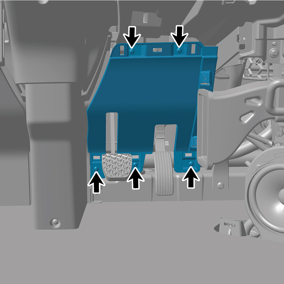
Remove 5 fixing screws of the IP right front upper trim
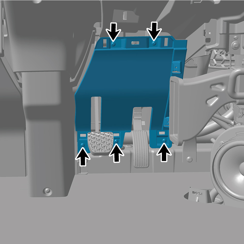
panel assembly.
9
Remove the IP right front upper trim panel assembly.
Installation Procedures
1
Move the IP right front upper trim panel assembly to the
mounting position.
2
Install 5 fixing screws of the IP right front upper trim panel
assembly.
3
Install the right switch panel lower trim panel assembly.
4
Install the right switch panel assembly.
5
Install the IP right front lower trim panel assembly.
6
Install the IP right access cover plate assembly.
7
Connect the battery negative cable.
8
Close the front flip cover plate.
9
Close the door.
6.11.3.20 Replacement of IP Right Front Lower Trim Panel Assembly
Trim Panel Assembly
Removal Procedures
1
Open the door.
2
Remove the IP right access cover plate assembly.
3
Remove 1 fixing screw of the IP right front lower trim panel
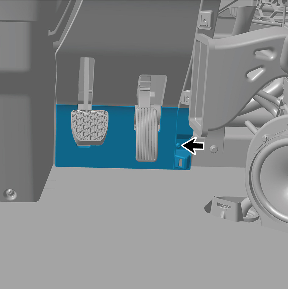
assembly.
4
Remove the IP right front lower trim panel assembly.
Installation Procedures
1
Move the IP right front lower trim panel assembly to the
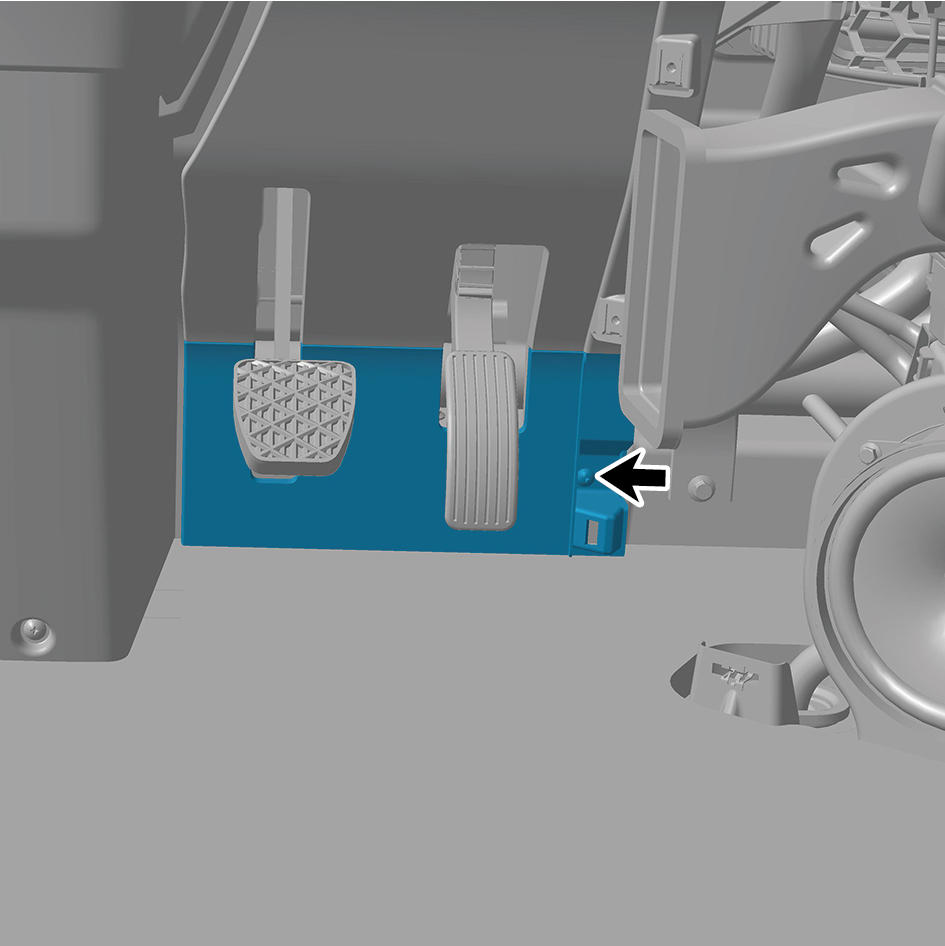
mounting position.
2
Install 1 fixing screw of the IP right front lower trim panel
assembly.
3
Install the IP right access cover plate assembly.
4
Close the door.
6.11.3.21 Replacement of Left Switch Panel Lower Trim Panel Assembly
Lower Trim Panel Assembly
Removal Procedures
1
Open the door.
2
Open the front flip cover plate.
3
Disconnect the battery negative cable.
caution
power down the high-voltage system before
disconnecting the negative pole of the storage
battery.
4
Remove the IP left access cover plate assembly.
5
Remove the left switch panel assembly.
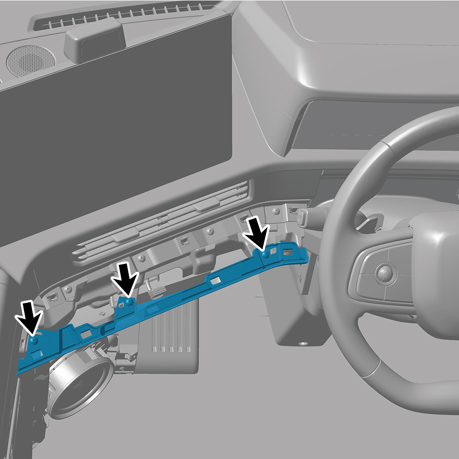
6
Remove 5 fixing screws of the left switch panel lower trim
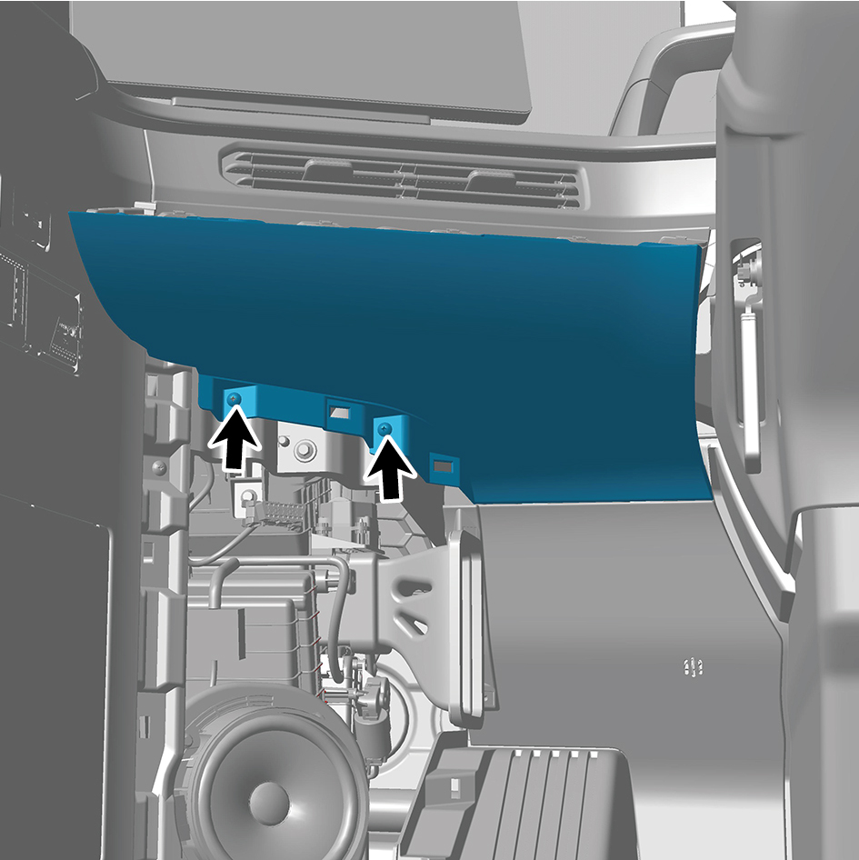
panel assembly.
7
Remove the left switch panel lower trim panel assembly.
Installation Procedures
1
Move the left switch panel lower trim panel assembly to
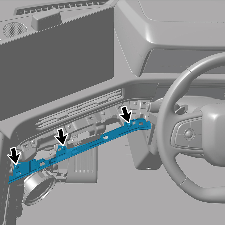
the mounting position.
2
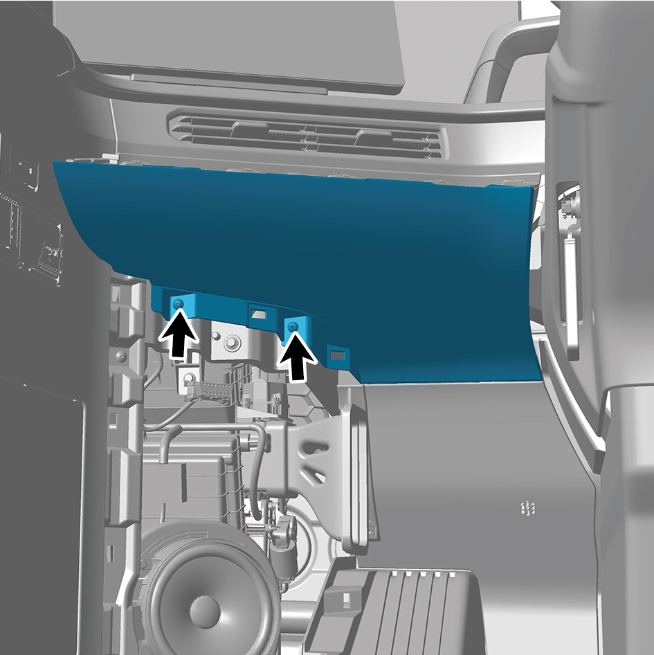
Install 5 fixing screws of the left switch panel lower trim
panel assembly.
3
Install the left switch panel assembly.
4
Install the IP left access cover plate assembly.
5
Connect the battery negative cable.
6
Close the front flip cover plate.
7
Close the door.
6.11.3.22 Replacement of Right Switch Panel Lower Trim Panel Assembly
Lower Trim Panel Assembly
Removal Procedures
1
Open the door.
2
Open the front flip cover plate.
3
Disconnect the battery negative cable.
caution
power down the high-voltage system before
disconnecting the negative pole of the storage
battery.
4
Remove the IP right access cover plate assembly.
5
Remove the right switch panel assembly.
6
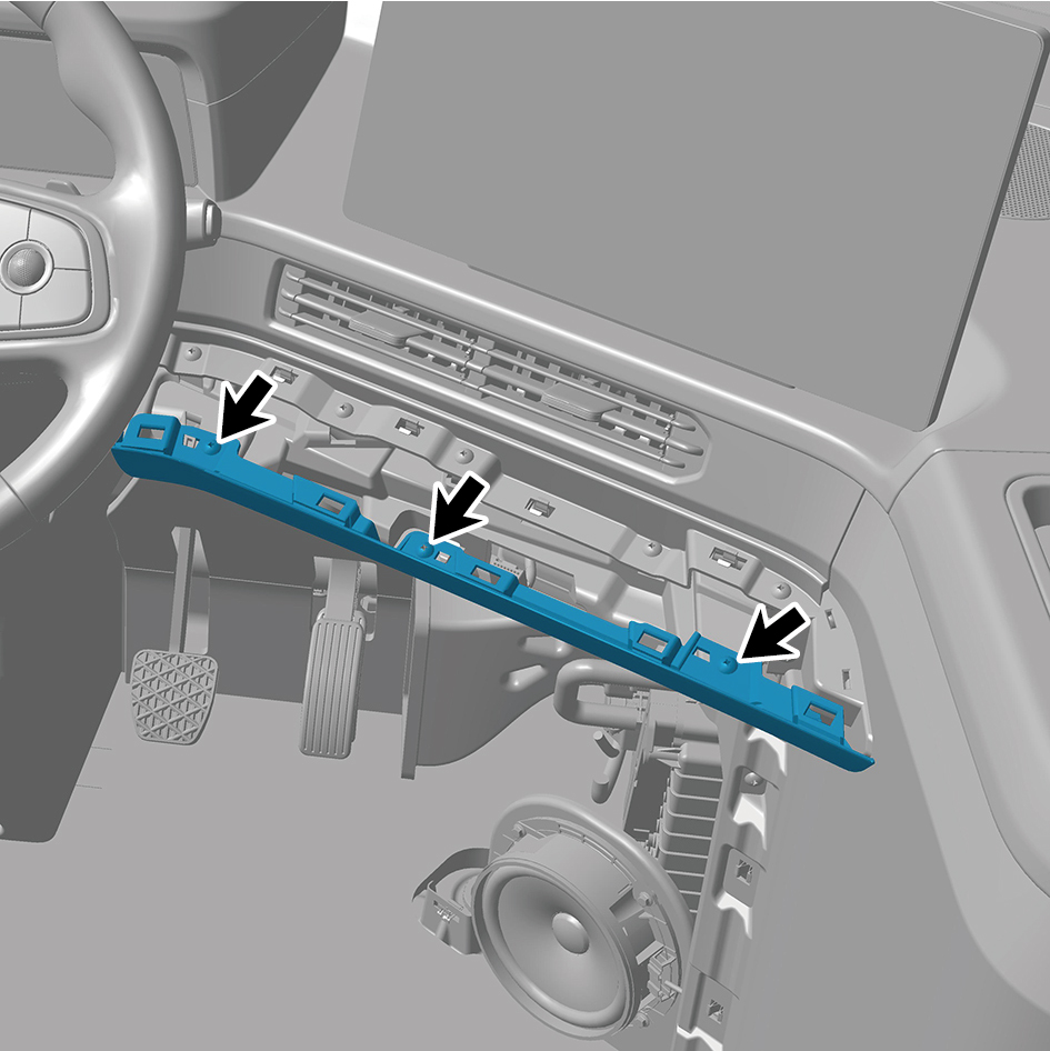
Remove 5 fixing screws of the right switch panel lower
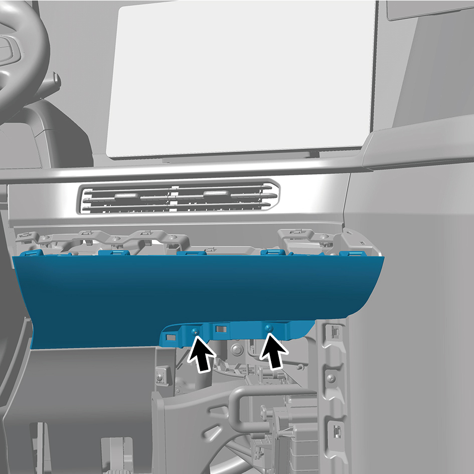
trim panel assembly.
7
Remove the right switch panel lower trim panel assembly.
Installation Procedures
1
Move the right switch panel lower trim panel assembly to
the mounting position.
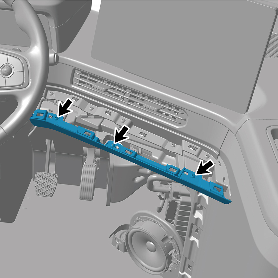
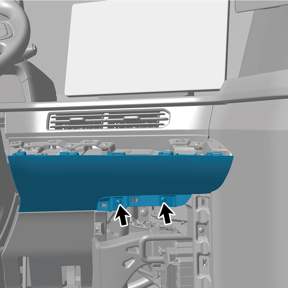
2
Install 5 fixing screws of the right switch panel lower trim
panel assembly.
3
Install the right switch panel assembly.
4
Install the IP right access cover plate assembly.
5
Connect the battery negative cable.
6
Close the front flip cover plate.
7
Close the door.
6.11.3.23 Replacement of Left Switch Panel Assembly
Assembly
Removal Procedures
1
Open the door.
2
Open the front flip cover plate.
3
Disconnect the battery negative cable.
caution
power down the high-voltage system before
disconnecting the negative pole of the storage
battery.
4
Detach the left switch panel assembly.
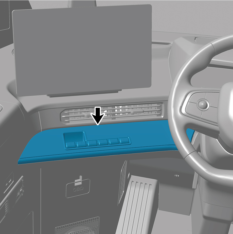
5
Disconnect 1 harness connector of the left switch panel
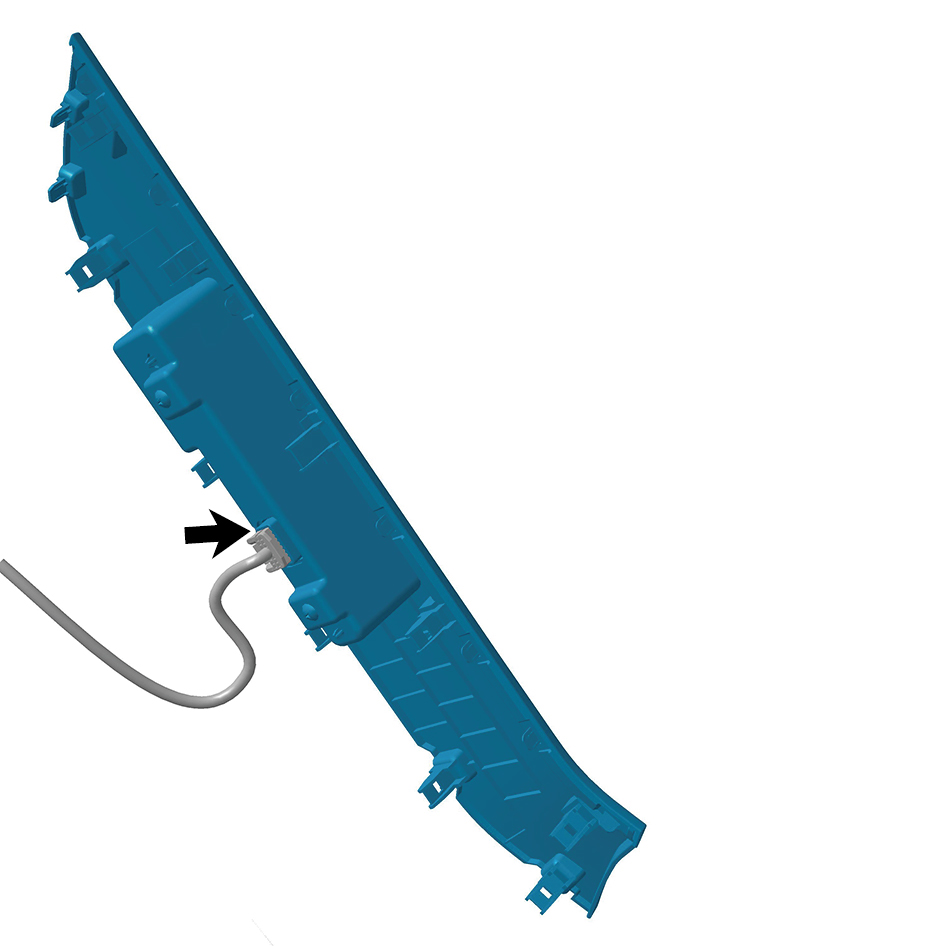
assembly.
6
Remove the left switch panel assembly.
Installation Procedures
1
Move the left switch panel assembly to the mounting
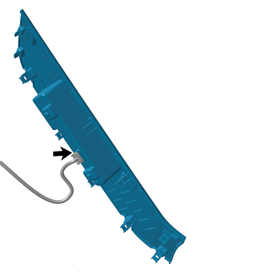
position.
2
Connect 1 harness connector of the left switch panel
assembly.
caution
The harness is firmly connected following the
principal of "insert until a click is heard for
confirmation".
3
Install the left switch panel assembly.
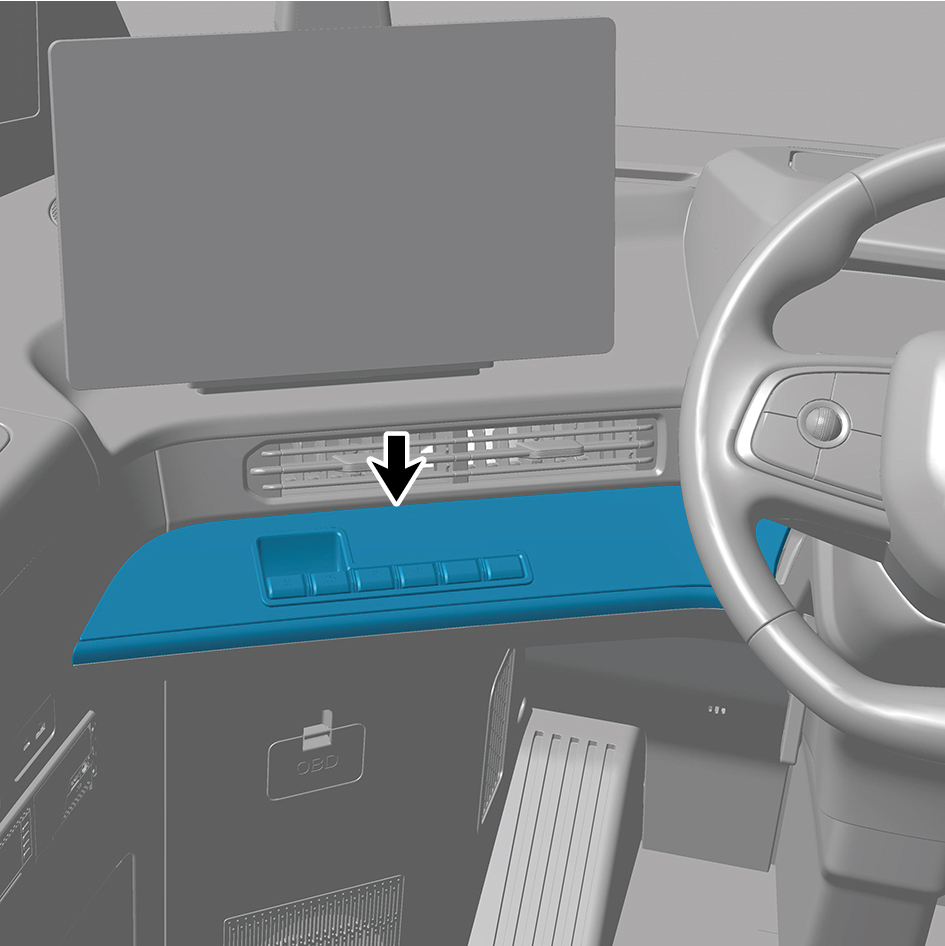
4
Connect the battery negative cable.
5
Close the front flip cover plate.
6
Close the door.
6.11.3.24 Replacement of Right Switch Panel Assembly
Assembly
Removal Procedures
1
Open the door.
2
Open the front flip cover plate.
3
Disconnect the battery negative cable.
caution
power down the high-voltage system before
disconnecting the negative pole of the storage
battery.
4
Detach the right switch panel assembly.
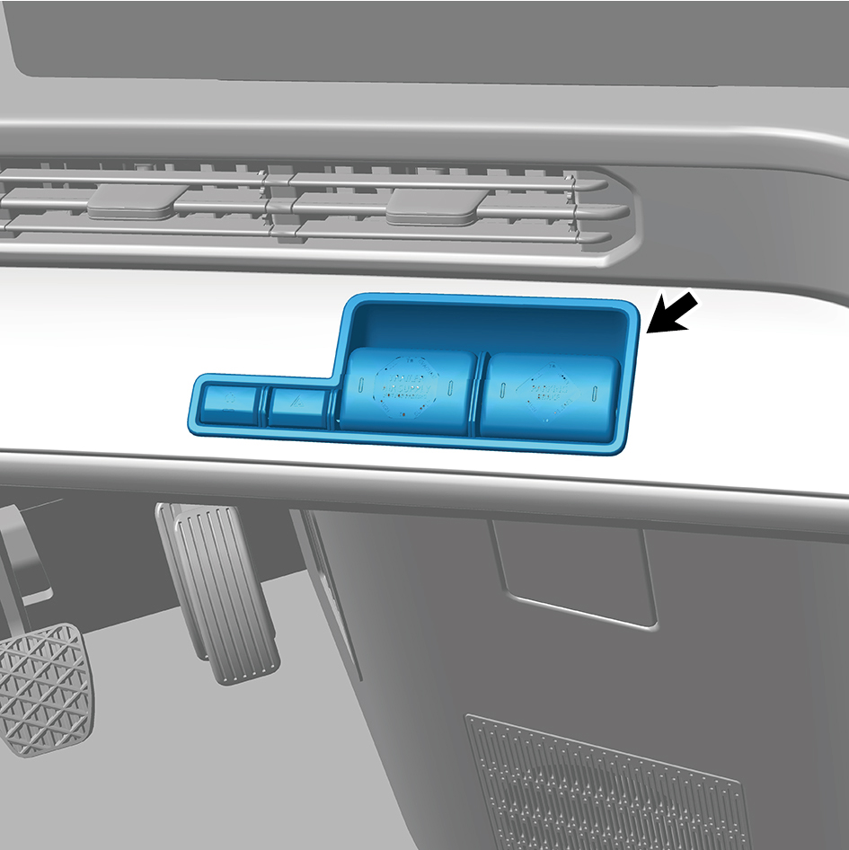
5
Disconnect 1 harness connector of the right switch panel
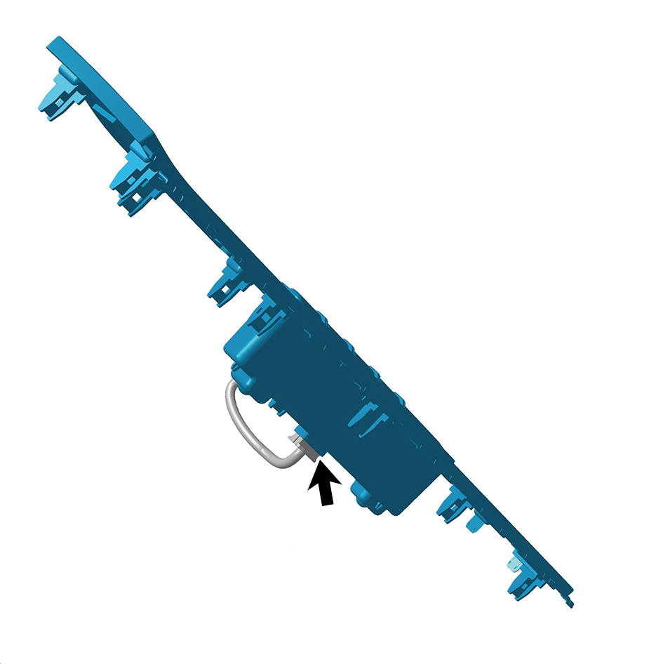
assembly.
6
Remove the right switch panel assembly.
Installation Procedures
1
Move the right switch panel assembly to the mounting
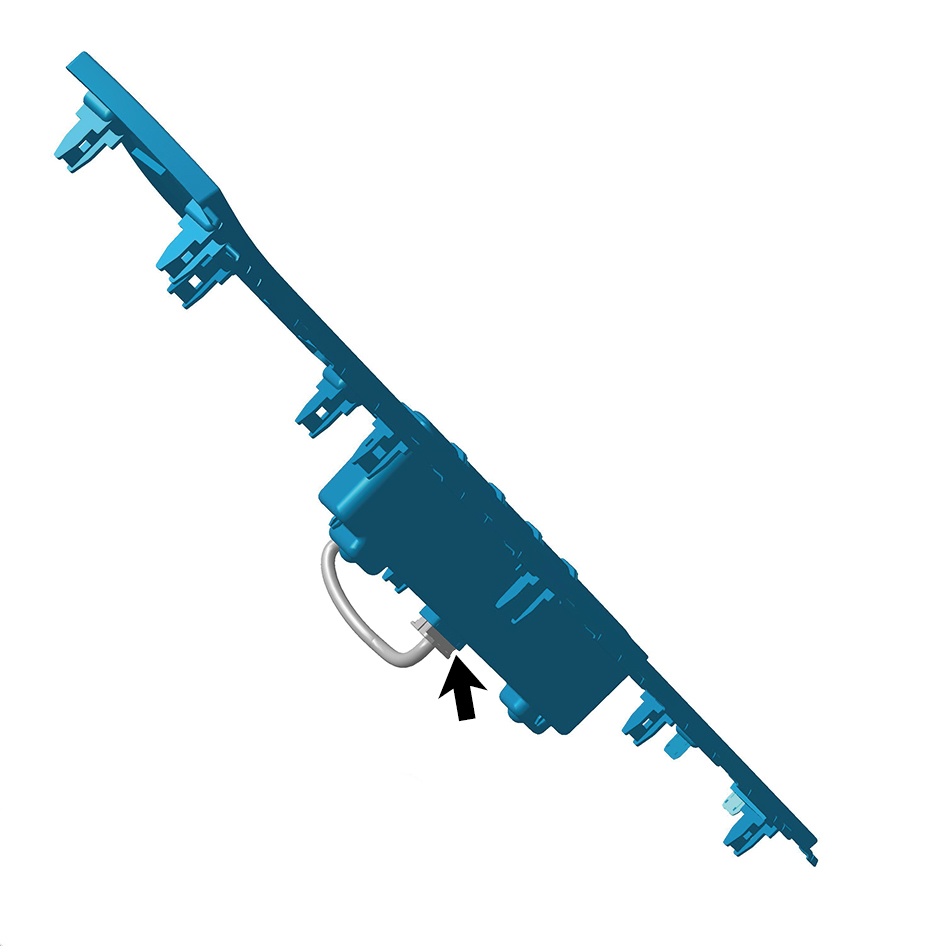
position.
2
Connect 1 harness connector of the right switch panel
assembly.
caution
The harness is firmly connected following the
principal of "insert until a click is heard for
confirmation".
3
Install the right switch panel assembly.
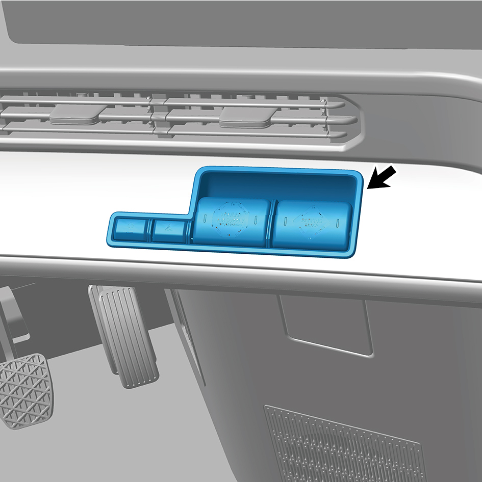
4
Connect the battery negative cable.
5
Close the front flip cover plate.
6
Close the door.
6.11.3.25 Replacement of IP Left Access Cover Plate Assembly
Cover Plate Assembly
Removal Procedures
1
Open the door.
2
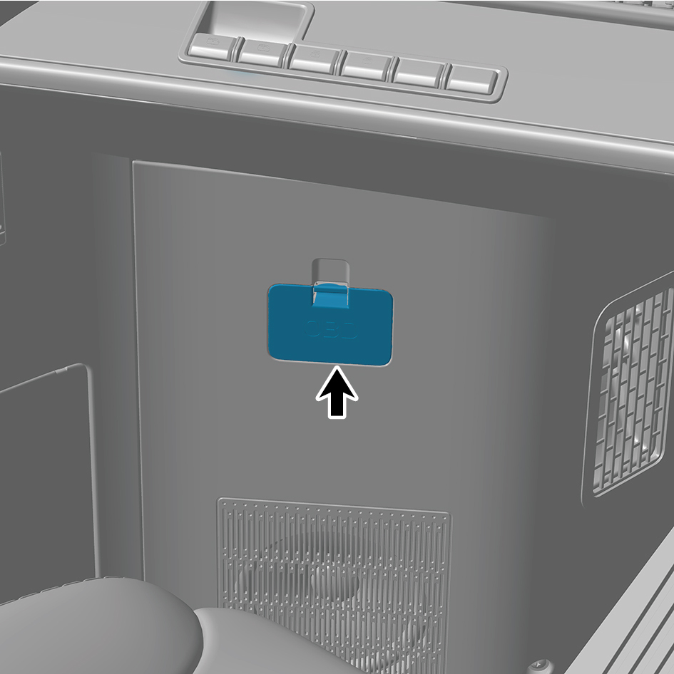
Remove the OBD cover plate.
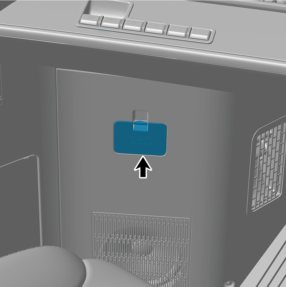
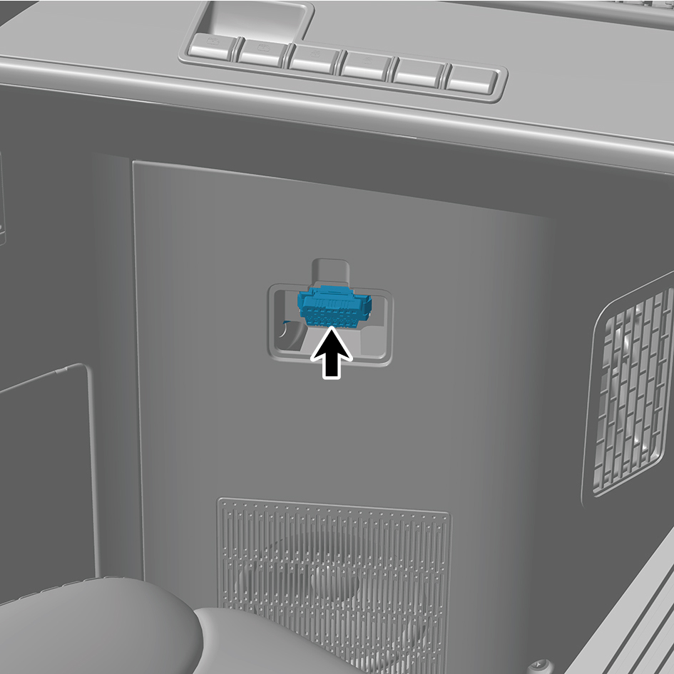
3
Detach the OBD harness interface.
4
Remove 3 fixing screws of the IP left access cover plate
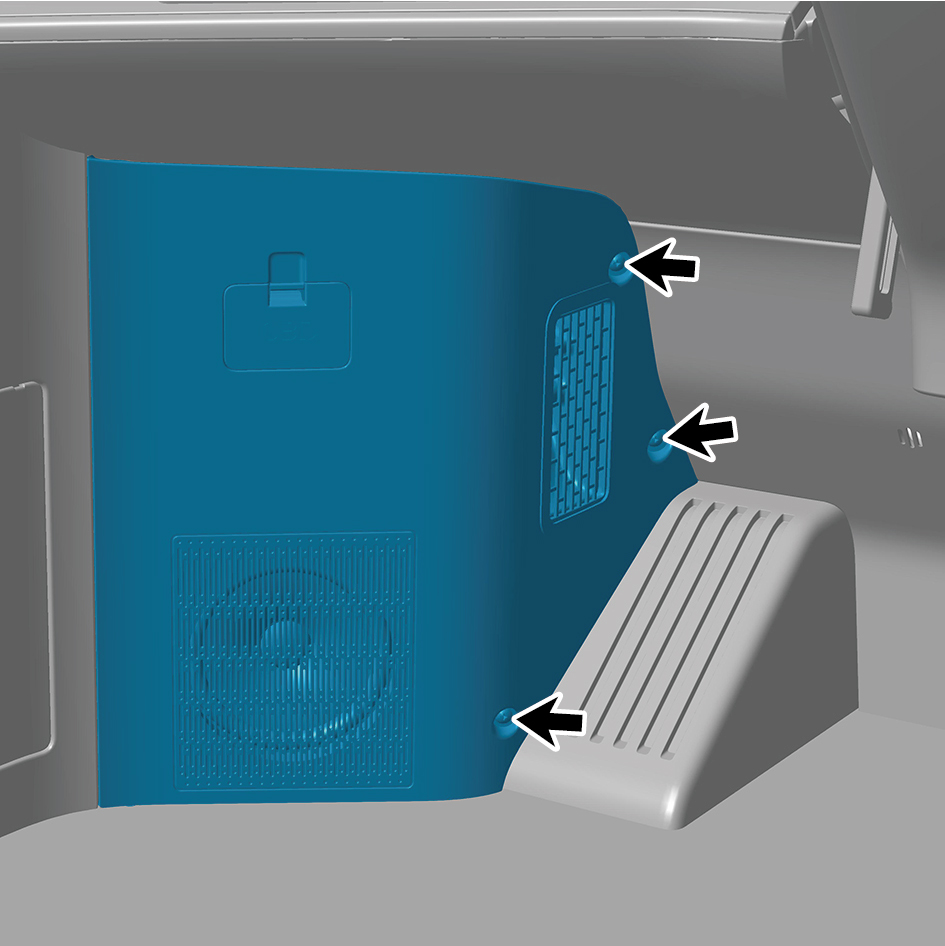
assembly.
5
Remove the IP left access cover plate assembly.
Installation Procedures
1
Move the IP left access cover plate assembly to the
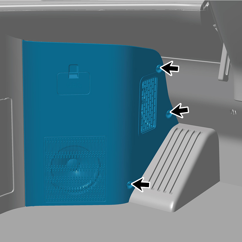
mounting position.
2
Install 3 fixing screws of the IP left access cover plate
assembly.
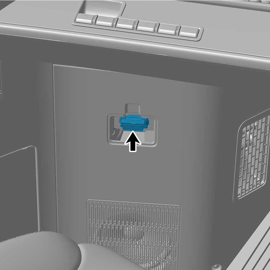
3
Connect the OBD harness interface.
4
Install the OBD cover plate.
5
Close the door.
6.11.3.26 Replacement of IP Right Access Cover Plate Assembly
Cover Plate Assembly
Removal Procedures
1
Open the door.
2
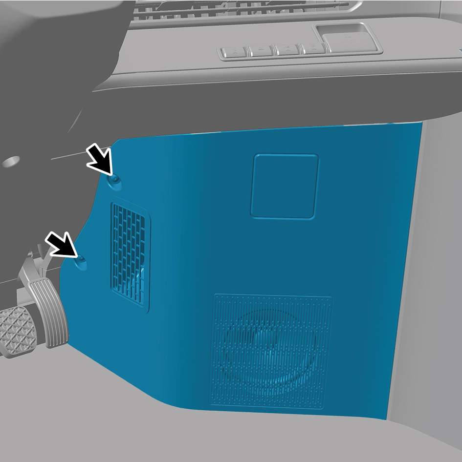
Remove 2 fixing screws of the IP right access cover plate
assembly.
3
Remove the IP right access cover plate assembly.
Installation Procedures
1
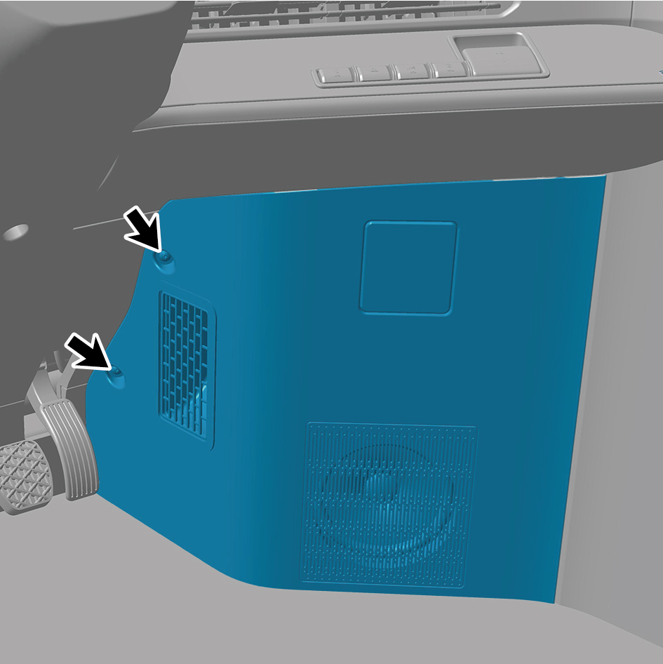
Move the IP right access cover plate assembly to the
mounting position.
2
Install 2 fixing screws of the IP right access cover plate
assembly.
3
Close the door.
6.11.3.27 Replacement of Combination Switch Lower Shield Mounting Bracket
Lower Shield Mounting Bracket
Removal Procedures
1
Open the door.
2
Remove the combination switch upper shield assembly.
3
Remove the steering wheel assy.
4
Remove the combination switch lower shield.
5
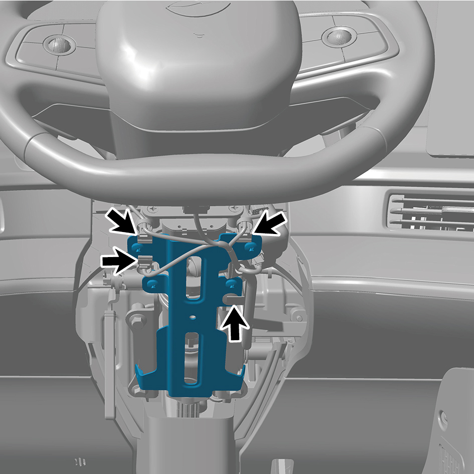
Disengage 4 clip of the IP harness.
6
Remove 4 fixing screws of the combination switch lower
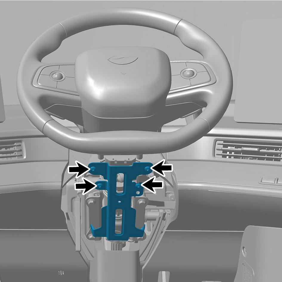
shield mounting bracket.
7
Remove the combination switch lower shield mounting
bracket.
Installation Procedures
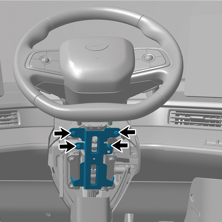
1
Move the combination switch lower shield mounting
bracket to the mounting position.
2
Install 4 fixing screws of the combination switch lower
shield mounting bracket.
3
Install 4 clip of the IP harness.
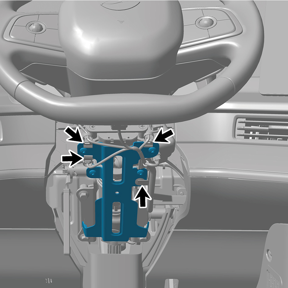
4
Install the combination switch lower shield.
5
Install the steering wheel assy.
6
Install the combination switch upper shield assembly.
7
Close the door.
6.11.3.28 Replacement of Combination Switch Lower Shield
Lower Shield
Removal Procedures
1
Open the door.
2
Remove the combination switch upper shield assembly.
3
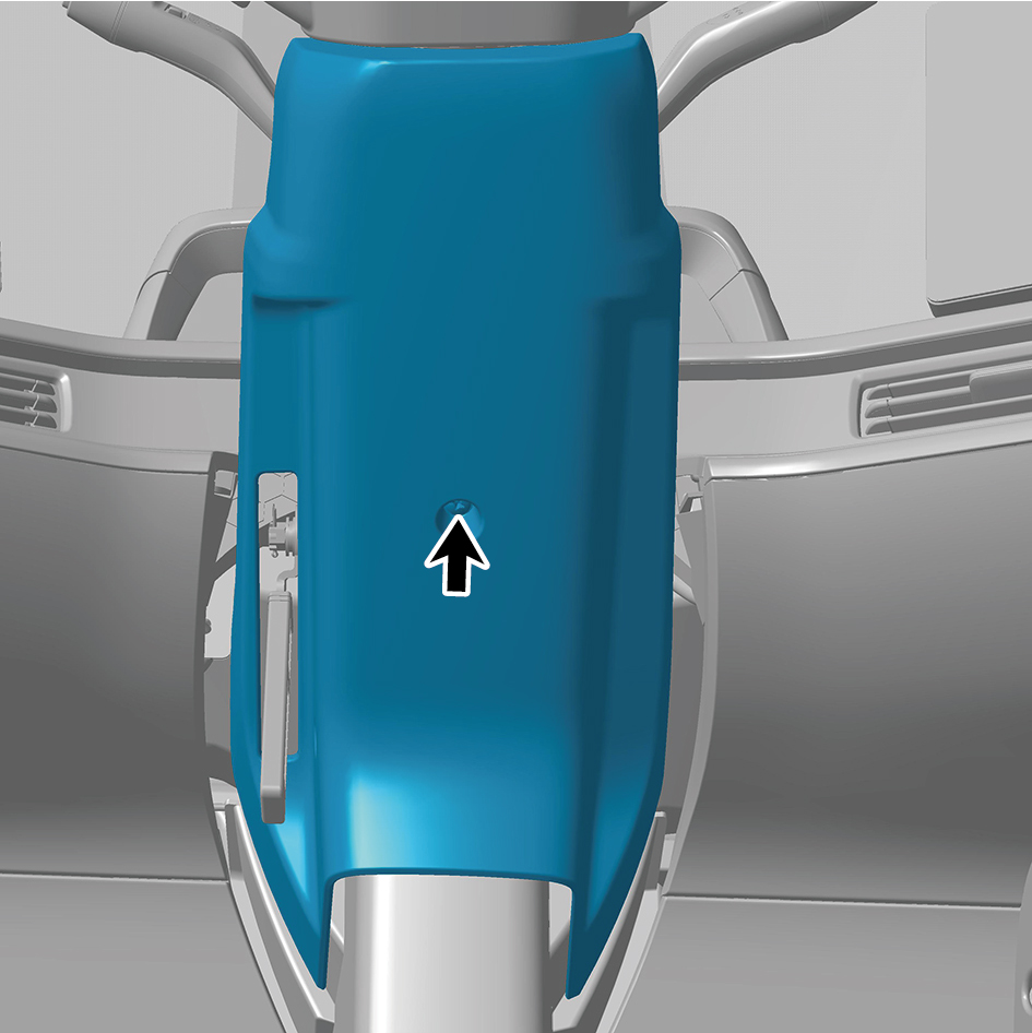
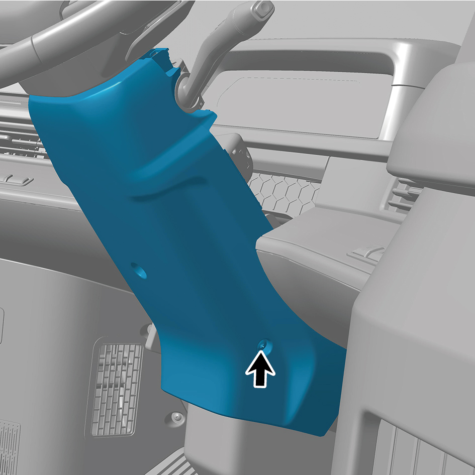
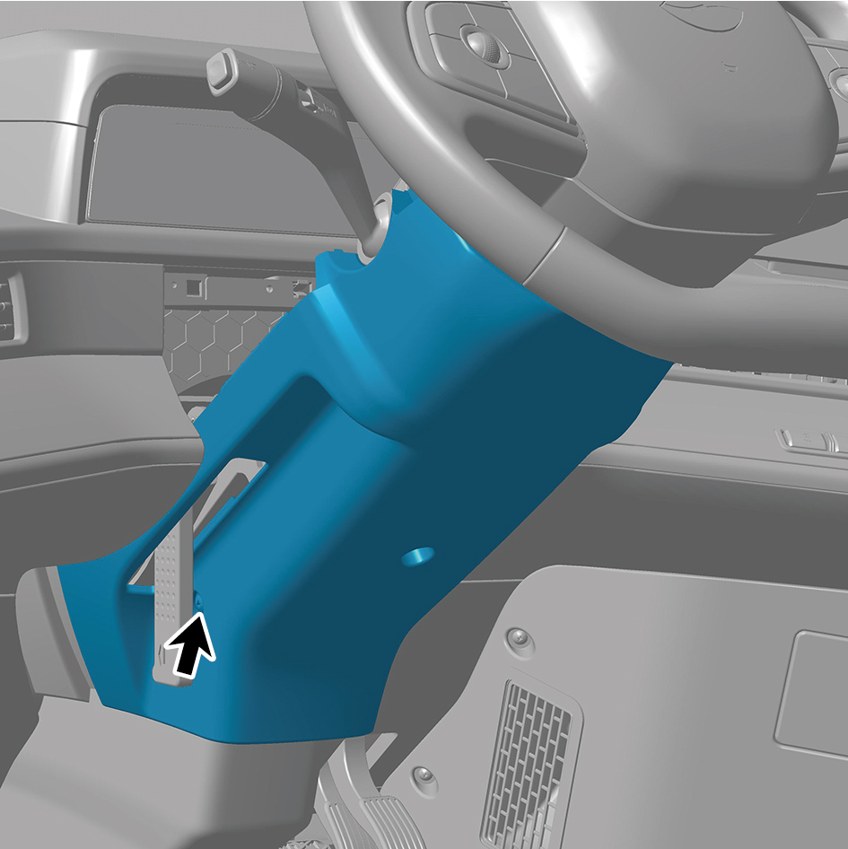
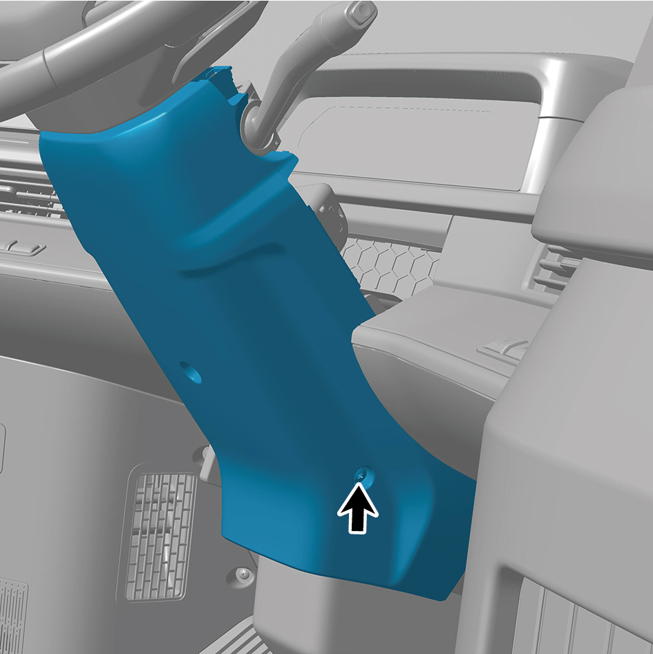
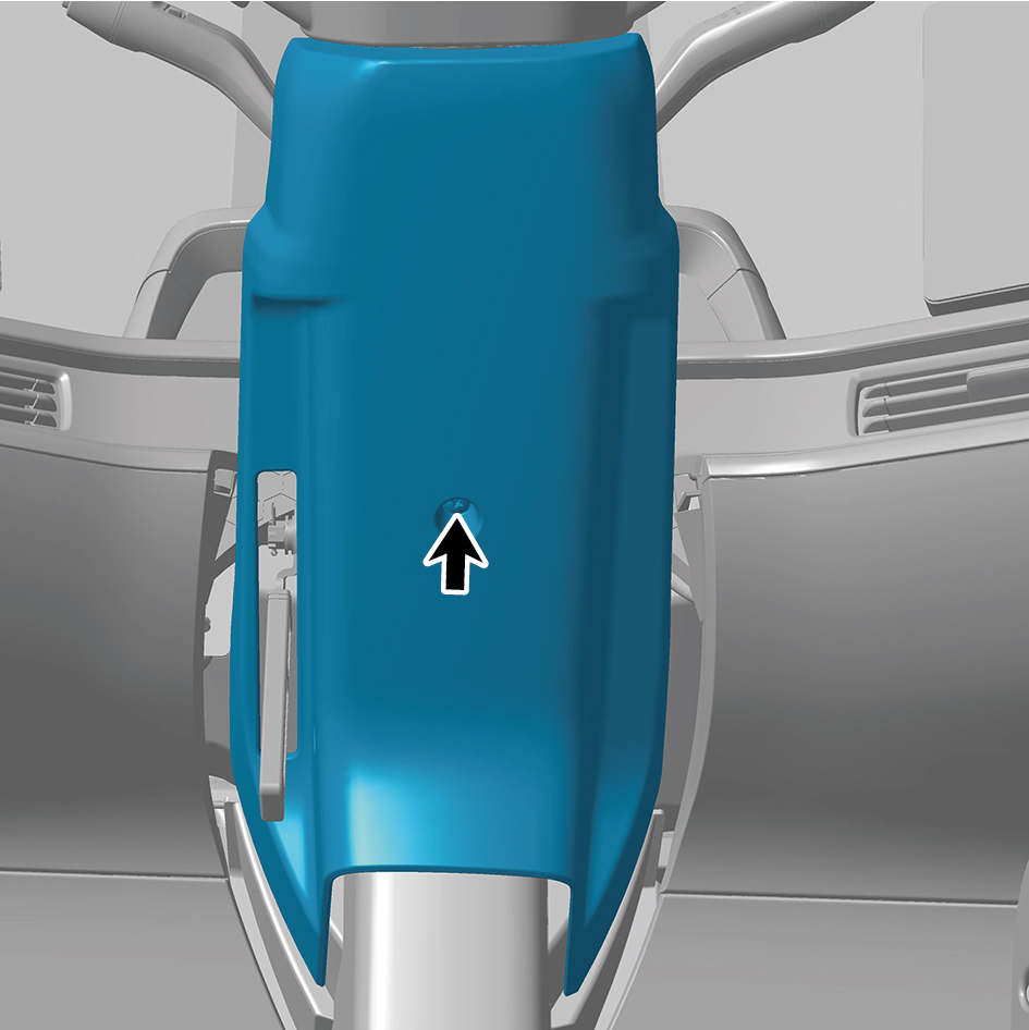
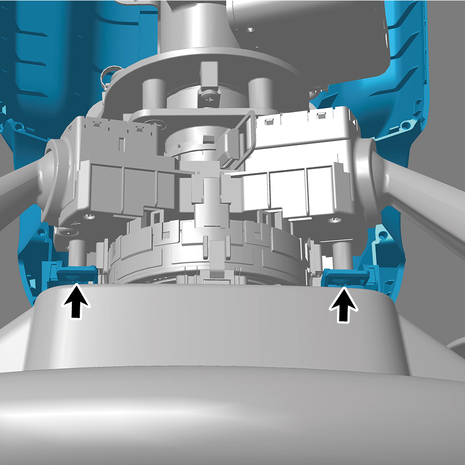
Remove 5 fixing screws of the combination switch lower
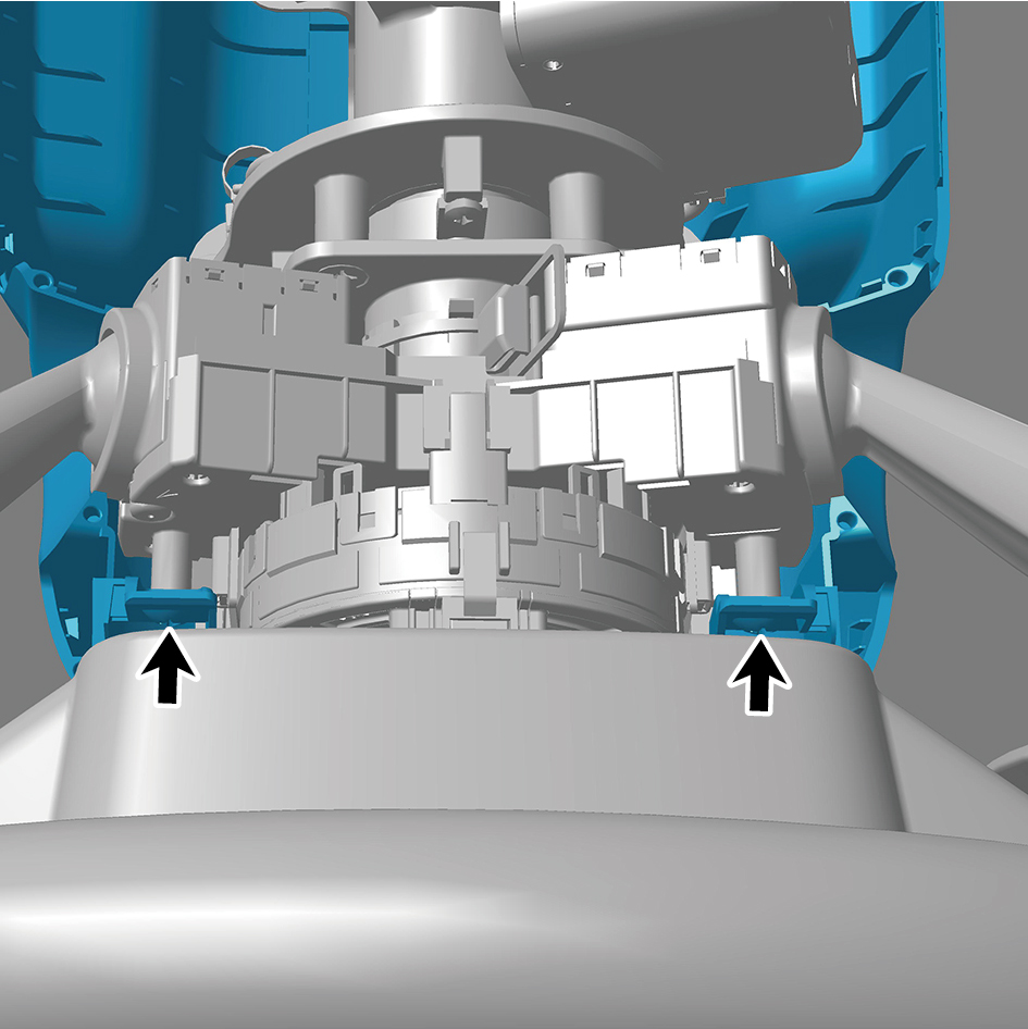
shield, and remove the combination switch lower shield.
Installation Procedures
1
Move the combination switch lower shield to the mounting
position.
2
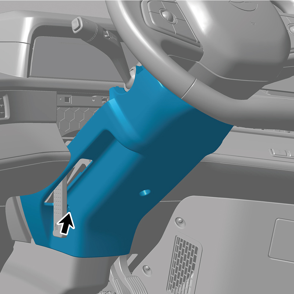
Install 5 fixing screws of the combination switch lower
shield.
3
Install the combination switch upper shield assembly.
4
Close the door.
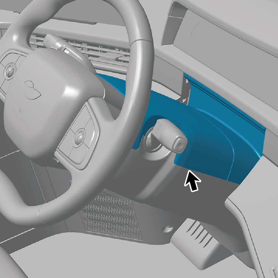
6.11.3.29 Replacement of Combination Switch Upper Shield Assembly
Upper Shield Assembly
Removal Procedures
1
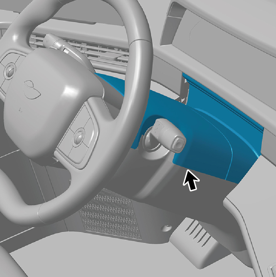
Open the door.
2
Remove the combination switch upper shield assembly.
Installation Procedures
1
Install the combination switch upper shield assembly.
2
Close the door.