← Back to Contents
6 Vehicle Body / 6.6 Side Skirt Panel Device | PDF pages 563-576
6.6 Side Skirt Panel Device
6.6 Side Skirt Panel Device
6.6.1 specifications
6.6.1.1 Fastener Specifications
Range Of Torque
Fastener Specifications
Specifications
Metric System(ft-lb)
The fixing bolt connecting the left skirt
(18 ft-lb +/- 2 ft-lb) ft-lb
M8
assembly and the frame assembly
The fixing bolt connecting the left skirt
(4.5 ft-lb +/- .75 ft-lb) ft-lb
M6
assembly and the skirt lower mounting
bracket
The fixing bolt connecting the right side
skirt assembly and the skirt lower
(18 ft-lb +/- 2 ft-lb) ft-lb
M8
mounting bracket
The fixing bolt connecting the right side
skirt assembly and the skirt lower
(4.5 ft-lb +/- .75 ft-lb) ft-lb
M6
mounting bracket
The fixing nut connecting the right side
skirt assembly and the right front
(18 ft-lb +/- 2 ft-lb) ft-lb
M8
assembly of the rear wheel cover
The fixing bolt connecting the right side
(18 ft-lb +/- 2 ft-lb) ft-lb
M8
skirt assembly to the bracket on the skirt
The fixing nut connecting the left skirt
(18 ft-lb +/- 2 ft-lb) ft-lb
M8
assembly and the left front assembly of
the rear wheel cover
The fixing bolt connecting the left skirt
(18 ft-lb +/- 2 ft-lb) ft-lb
M8
assembly to the bracket on the skirt
The fixing bolt connecting the rear step
(18 ft-lb +/- 2 ft-lb) ft-lb
M8
assembly and the side skirt assembly
6.6.2 Decomposition Diagram
6.6.2.1 Decomposition Diagram
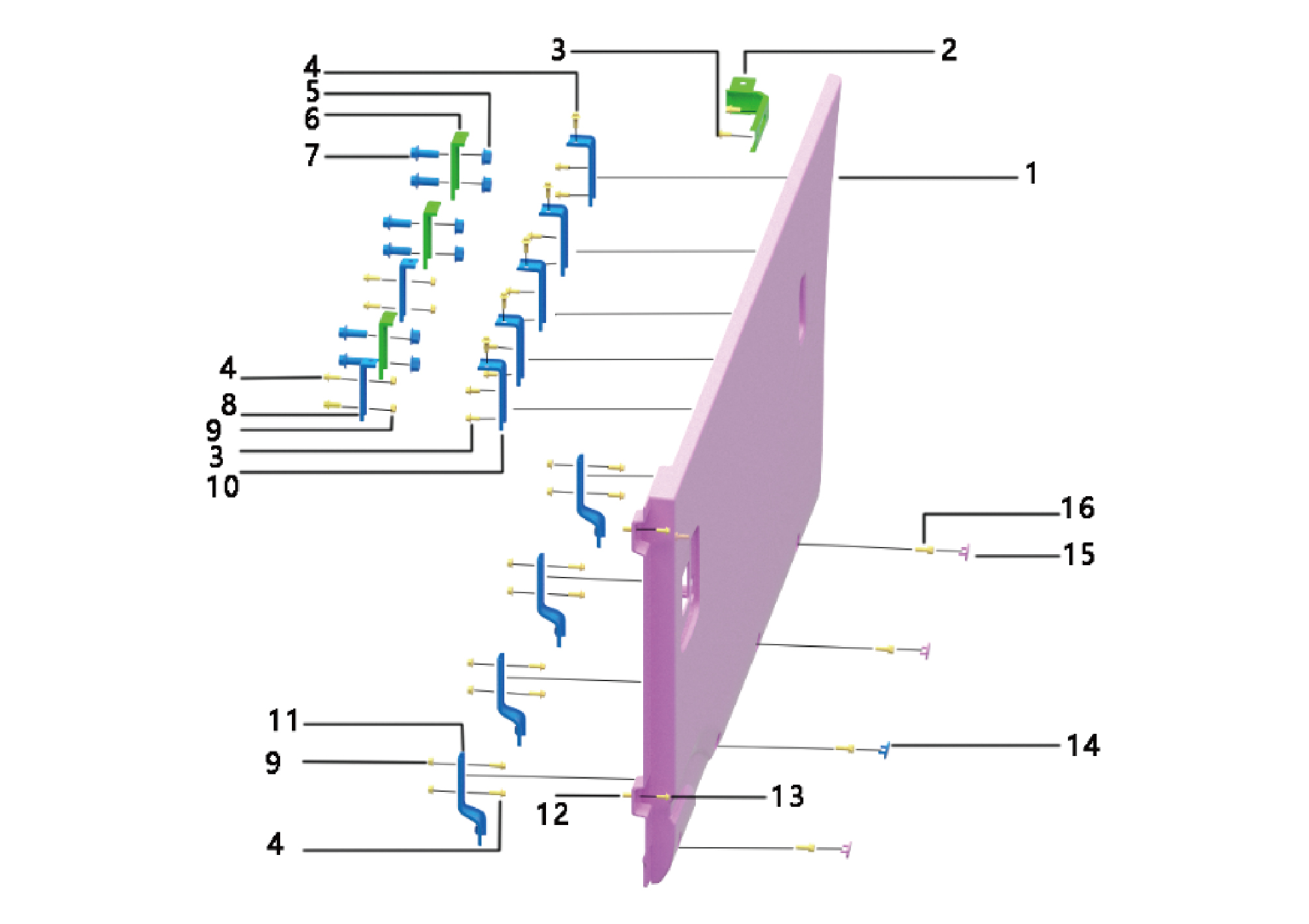
1.
9.
Hexagon Flange Nut
Skirt Assy-Lh
2.
Brkt-Lh Rr Wheel Arch Attachment
10.
Upr Attach Brkt-Skirt
3.
Hexagon Flange Bolt
11.
Brkt-Skrit Lower
4.
Hexagon Flange Bolt
12.
Riveted Nut
5.
13.
Hexagon Flange Nut
Hexagon Flange Bolt
6.
14.
Skrit Bracket
Pulg-Side Skirt Trim
7.
15.
Hexagon Flange Bolt
Pulg-Side Skirt Trim
8.
16.
Hexagon Head Bolt Assy
Brkt-Skrit Upper
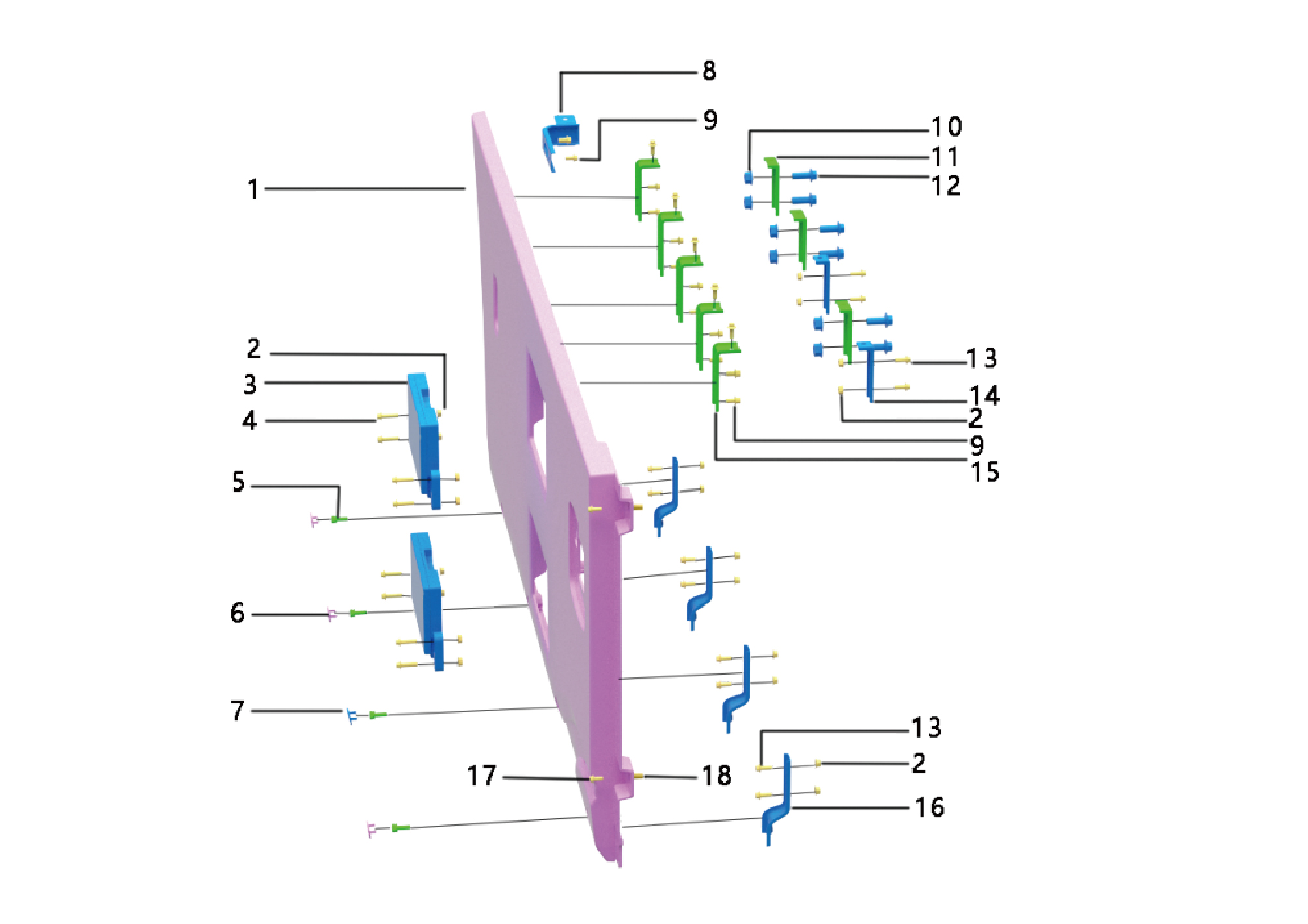
1.
10.
Hexagon Flange Nut
Skrit Plate-Rh
2.
Hexagon Flange Nut
11.
Skrit Bracket
3.
12.
Hexagon Flange Bolt
Rear Step Assy
4.
Hexagon Flange Bolt
13.
Hexagon Flange Bolt
5.
Hexagon Head Bolt Assy
14.
Brkt-Skrit Upper
6.
15.
Pulg-Side Skirt Trim
Upr Attach Brkt-Skirt
7.
16.
Pulg-Side Skirt Trim
Brkt-Skrit Lower
8.
Brkt-Rh Rr Wheel Arch Attachment
17.
Hexagon Flange Bolt
9.
Hexagon Flange Bolt
18.
Riveted Nut
6.6.3 Dismantling and Installation
6.6.3.1 Replacement of Left Skirt Plate Assembly
Assembly
Removal Procedures
1
Open the door.
2
Open the front flip cover plate.
3
Disconnect the battery negative cable.
caution
power down the high-voltage system before
disconnecting the negative pole of the storage
battery.
4
Remove the left side wall lower trim panel assembly.
5
Remove 5 fixing bolts of the left skirt plate assembly.
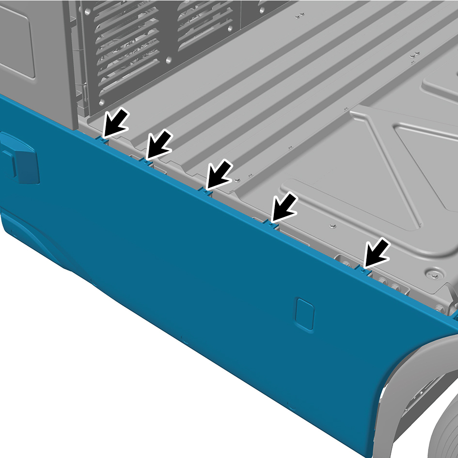
6
Remove 1 fixing nut of the left skirt plate assembly.
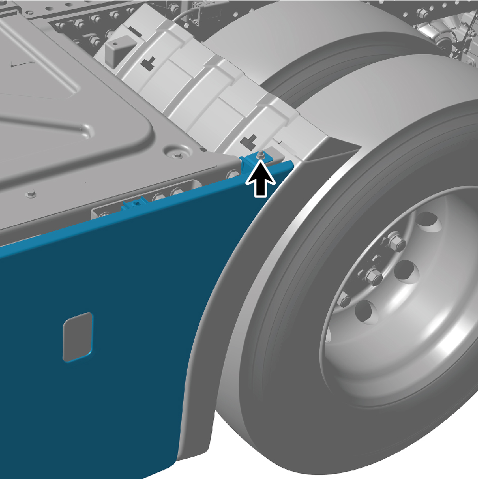
7
Remove 4 protection covers.
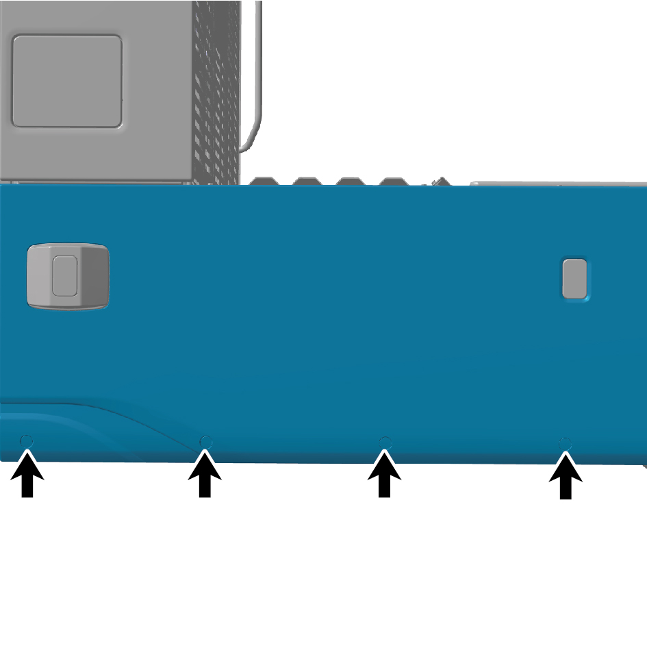
8
Remove 2 fixing bolts of the left skirt plate assembly.
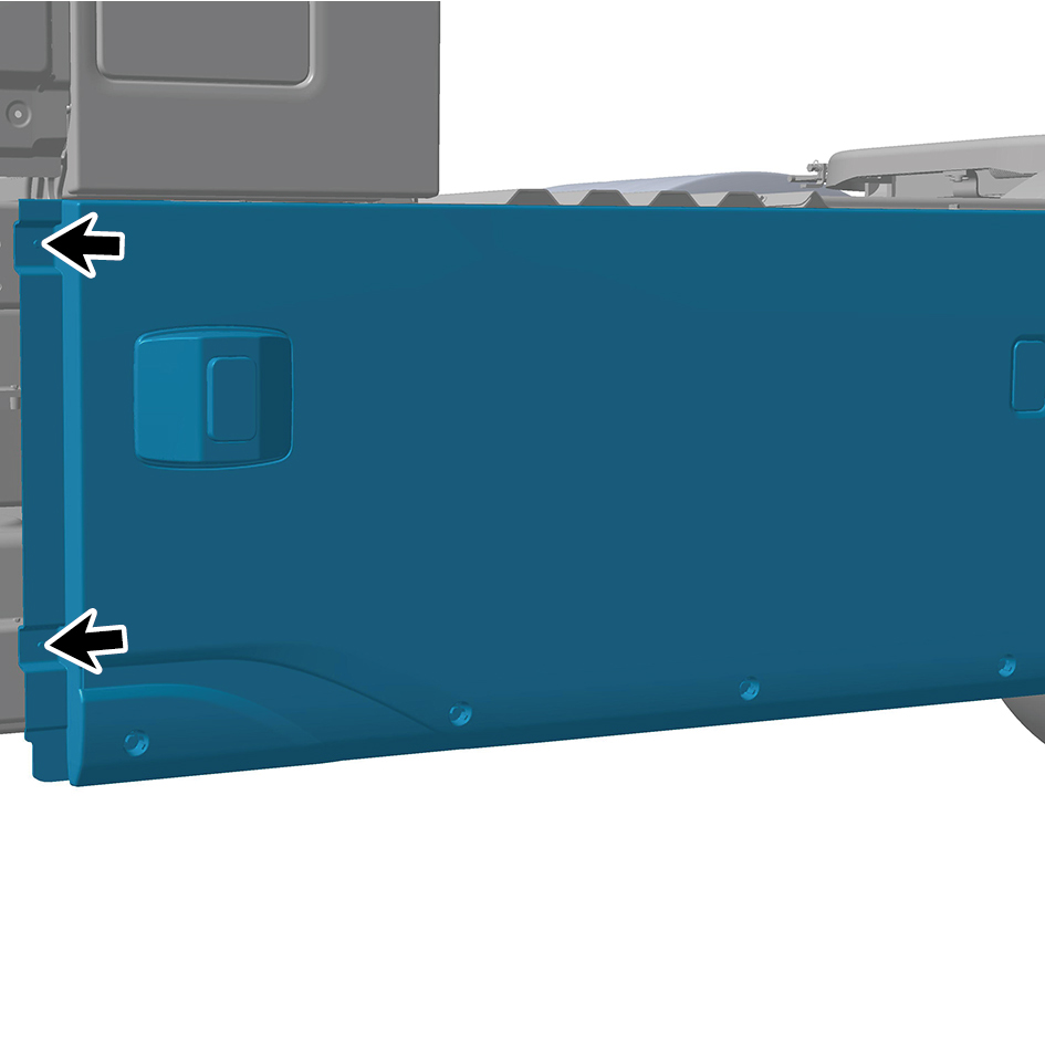
9
Remove 4 fixing bolts of the left skirt plate assembly.
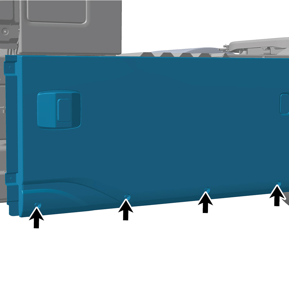
10
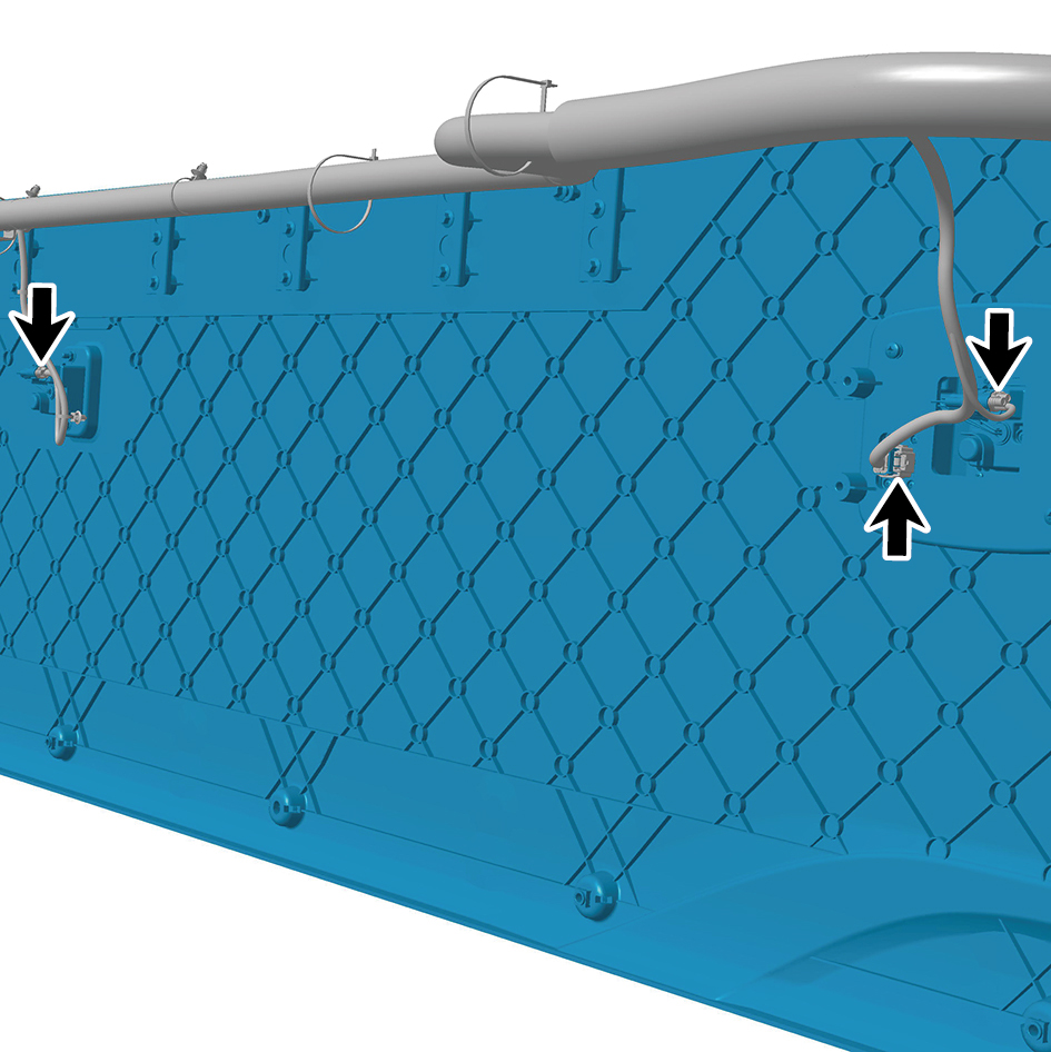
Disconnect 3 harness connectors of the left skirt plate
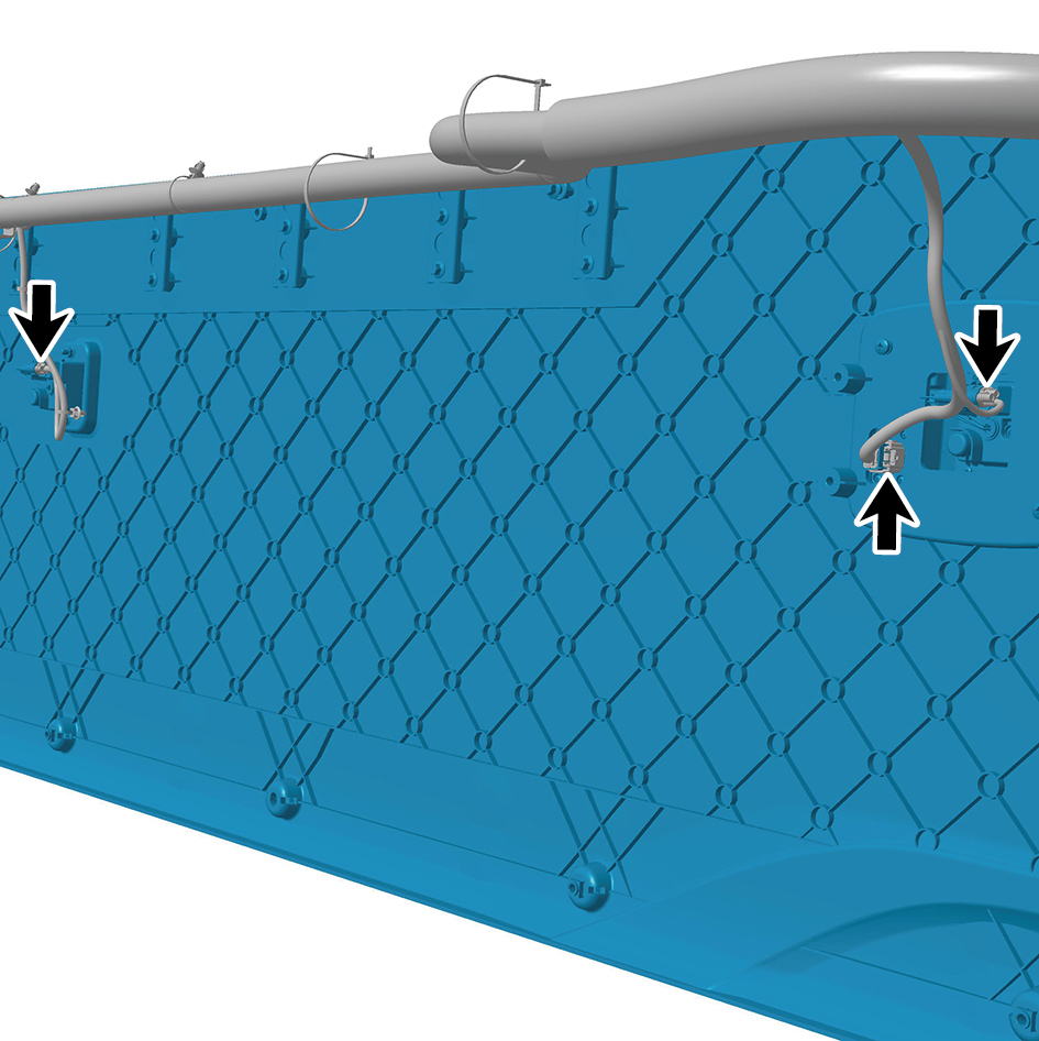
assembly.
11
Remove the left skirt plate assembly.
Installation Procedures
1
Move the left skirt plate assembly to the mounting
position.
2
Connect 3 harness connectors of the left skirt plate
assembly.
caution
The harness is firmly connected following the
principal of "insert until a click is heard for
confirmation".
3
Install 4 fixing bolts of the left skirt plate assembly.
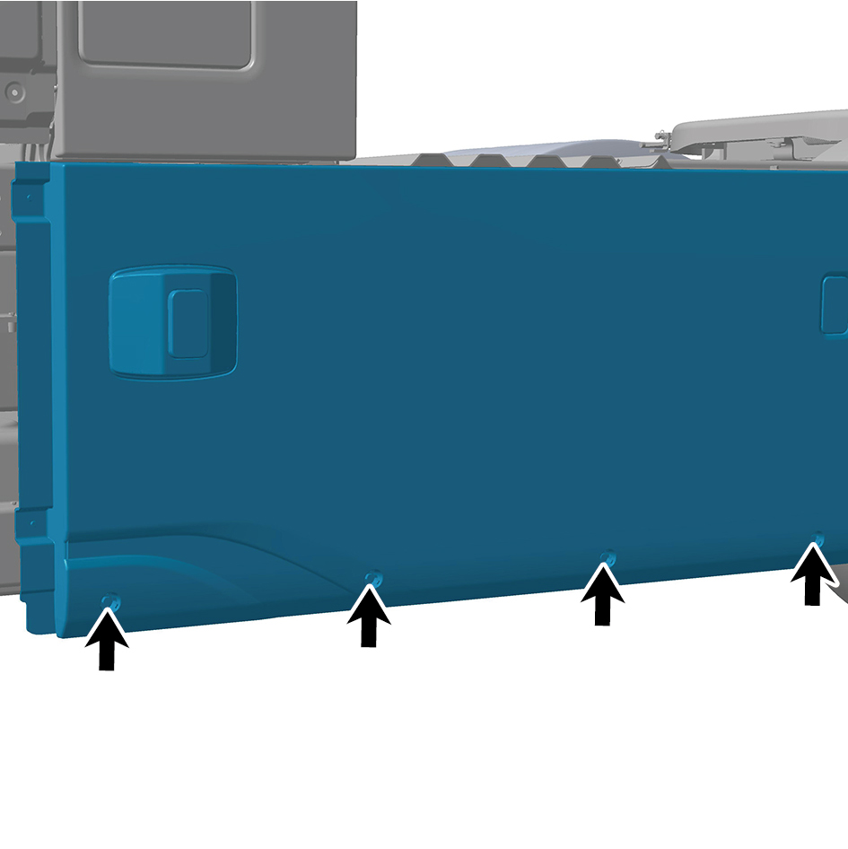
Torque:(18 ft-lb +/- 2 ft-lb) ft-lb
4
Install 2 fixing bolts of the left skirt plate assembly.
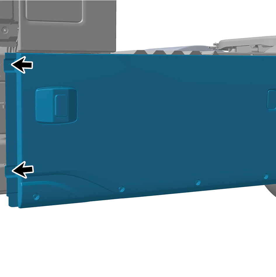
Torque: (4.5 ft-lb +/- .75 ft-lb) ft-lb
5
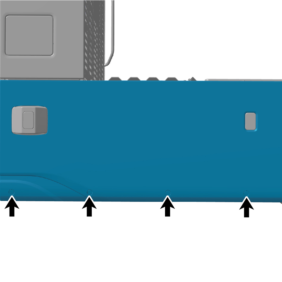
Install 4 protection covers.
6
Install 1 fixing nut of the left skirt plate assembly.
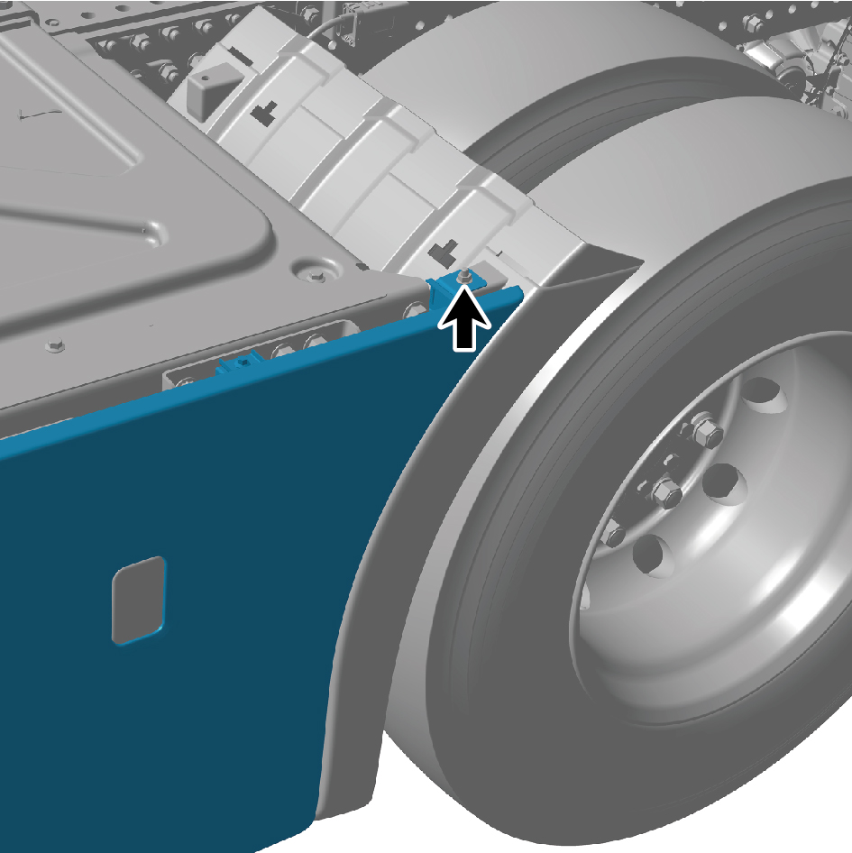
Torque: (18 ft-lb +/- 2 ft-lb) ft-lb
7
Install 5 fixing bolts of the left skirt plate assembly.
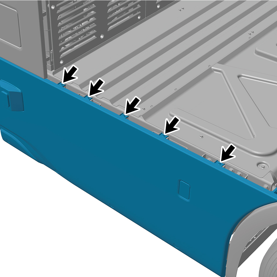
Torque: (18 ft-lb +/- 2 ft-lb) ft-lb
8
Install the left side wall lower trim panel assembly.
9
Connect the battery negative cable.
10
Close the front flip cover plate.
11
Close the door.
6.6.3.2 Replacement of Right Skirt Plate Assembly
Assembly
Removal Procedures
1
Open the door.
2
Open the front flip cover plate.
3
Disconnect the battery negative cable.
caution
power down the high-voltage system before
disconnecting the negative pole of the storage
battery.
4
Remove the right side wall lower trim panel assembly.
5
Remove 5 fixing bolts of the right skirt plate assembly.
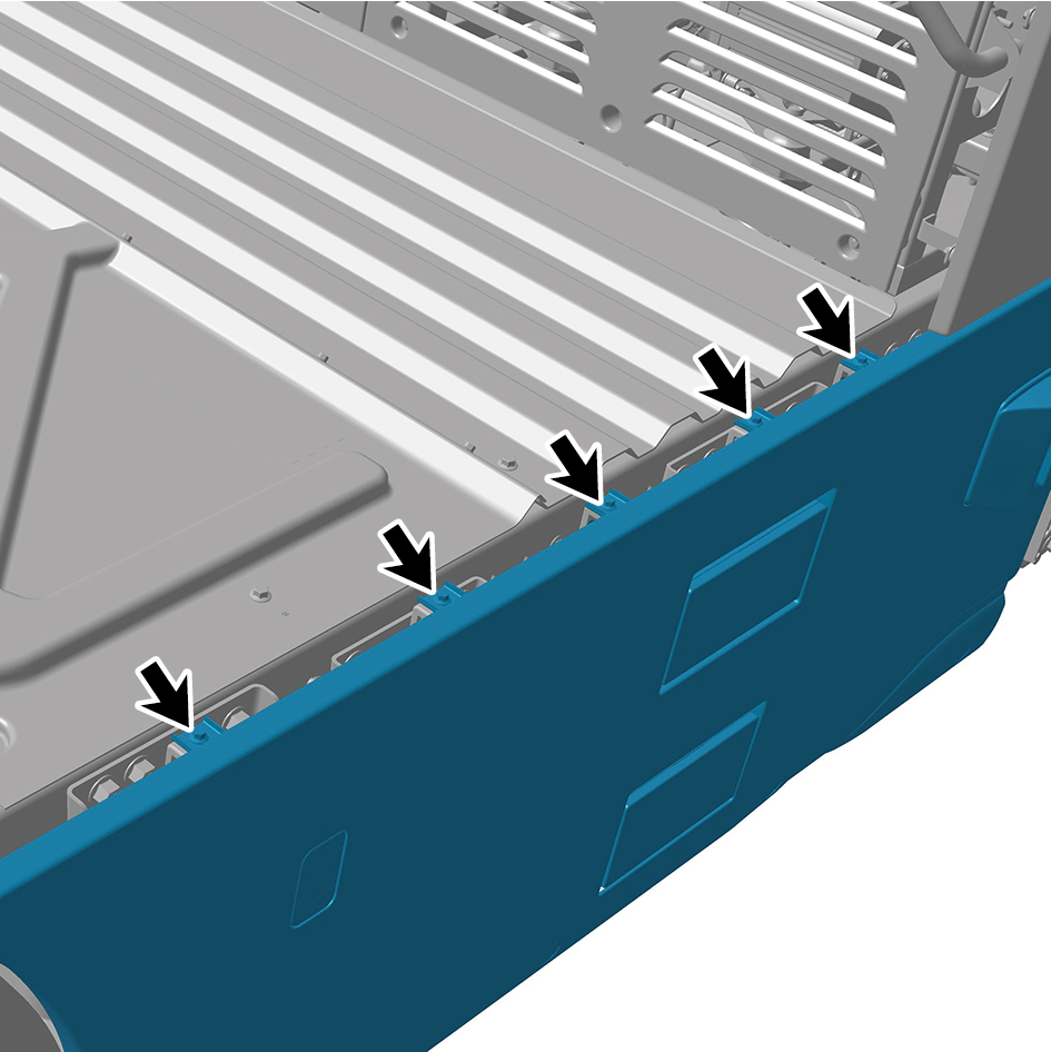
6
Remove 1 fixing nut of the right skirt plate assembly.
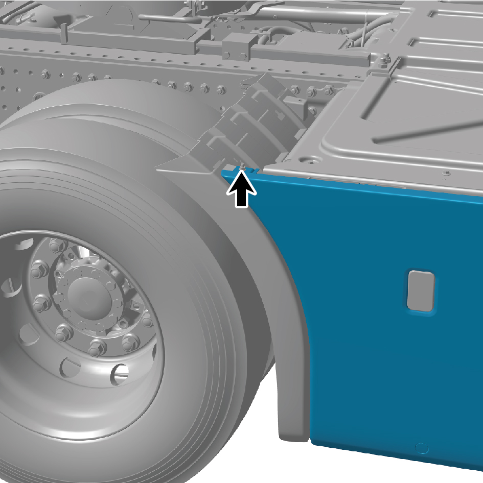
7
Remove 4 protection covers.
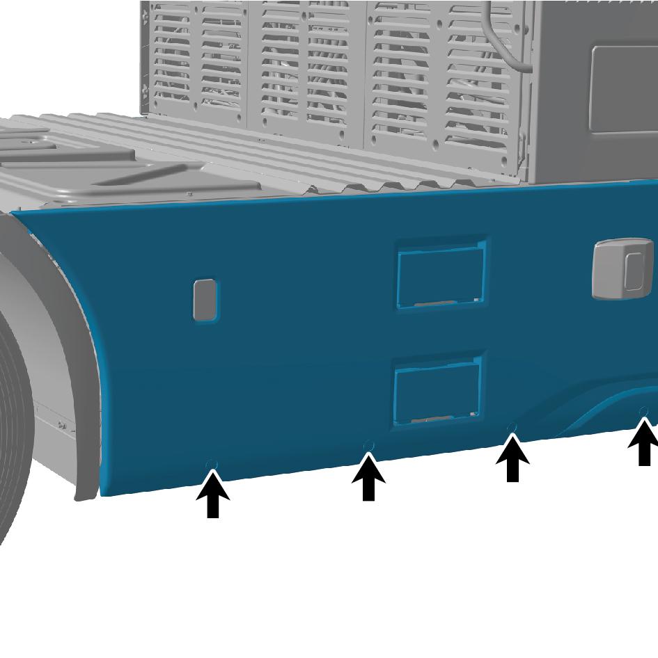
8
Remove 2 fixing bolts of the right skirt plate assembly.
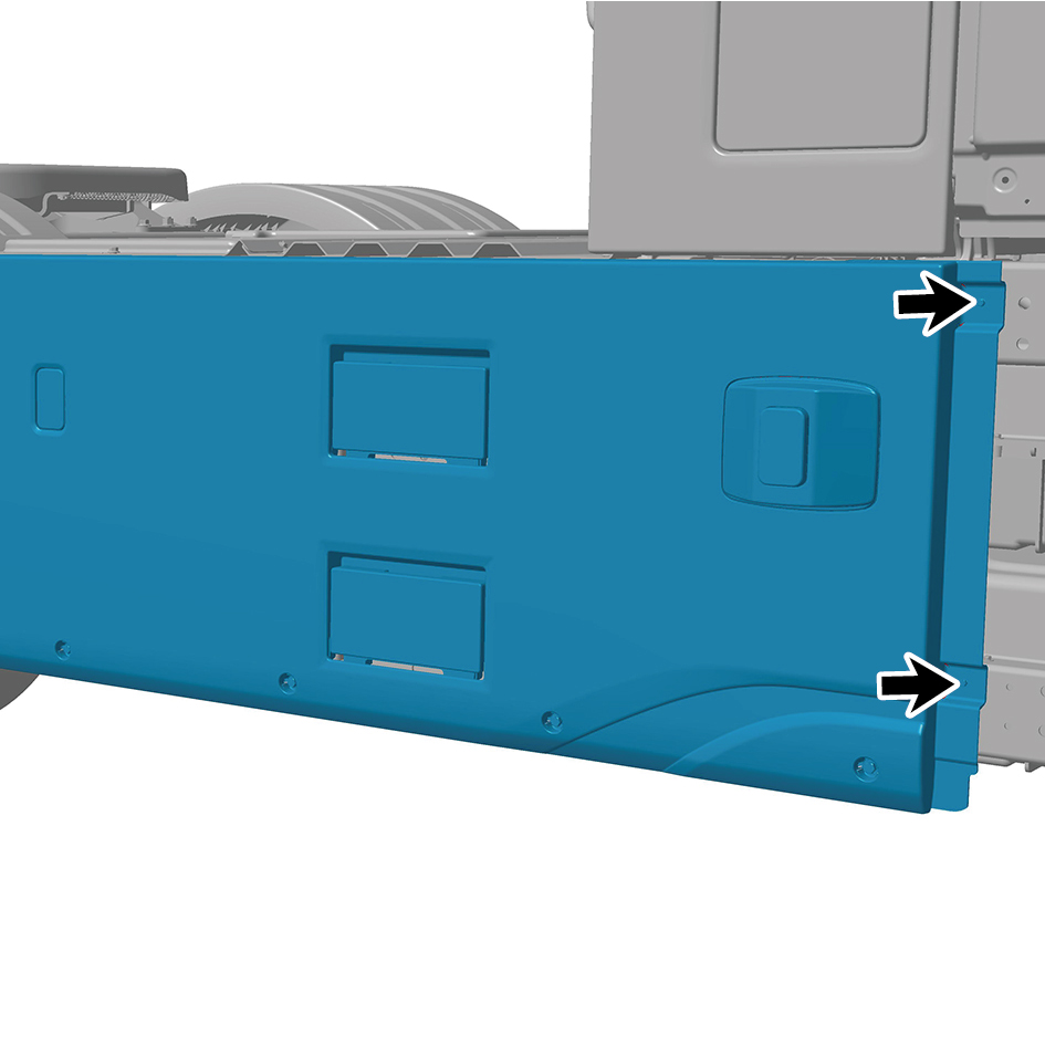
9
Remove 4 fixing bolts of the right skirt plate assembly, and
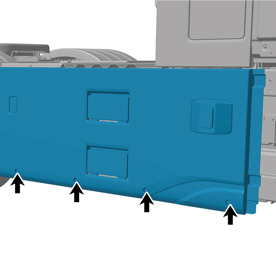
detach the right skirt plate assembly.
10
Disconnect 3 harness connectors of the right skirt plate
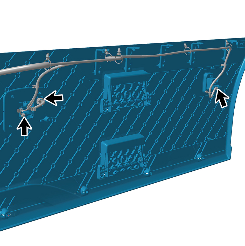
assembly.
11
Remove the right skirt plate assembly.
Installation Procedures
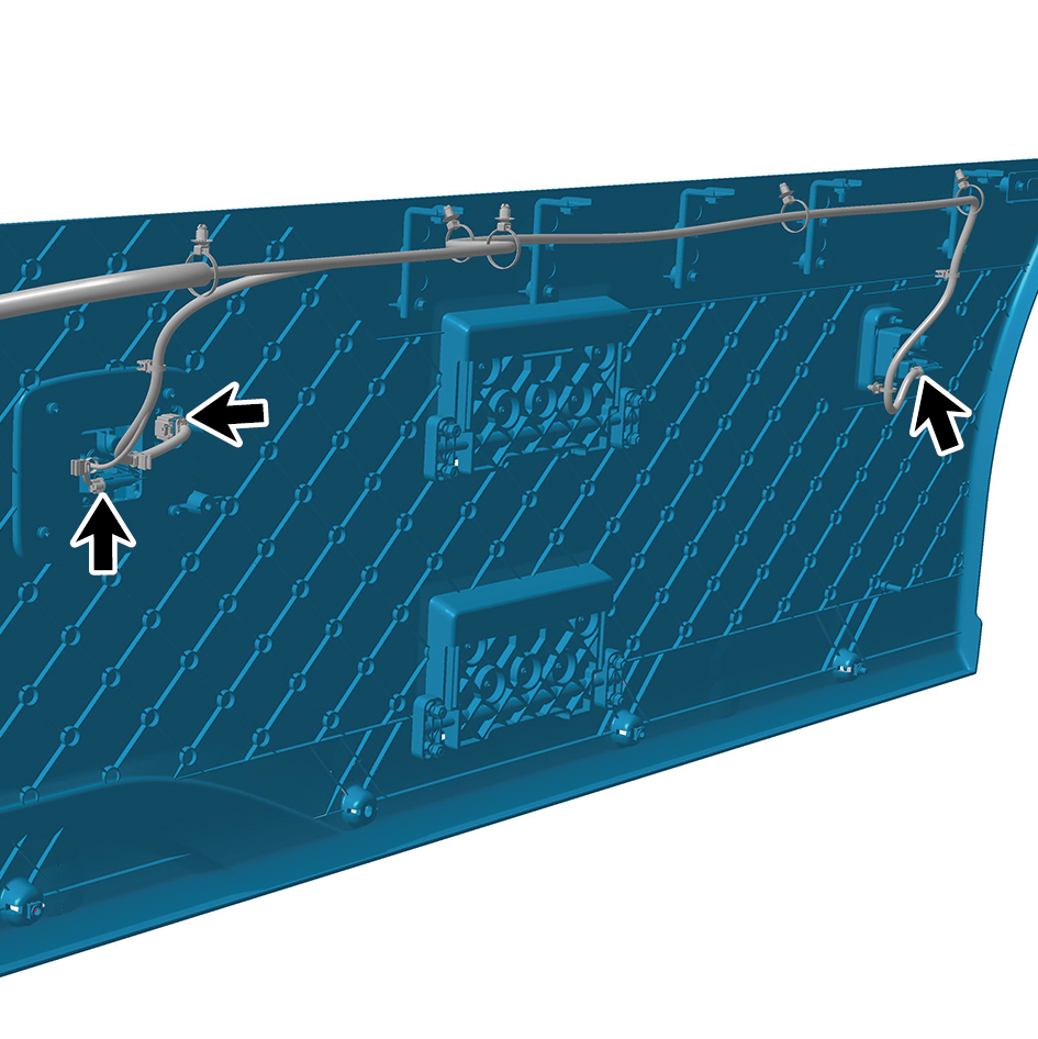
1
Move the right skirt plate assembly to the mounting
position.
2
Connect 3 harness connectors of the right skirt plate
assembly.
caution
The harness is firmly connected following the
principal of "insert until a click is heard for
confirmation".
3
Connect the right skirt plate assembly, and install 4 fixing
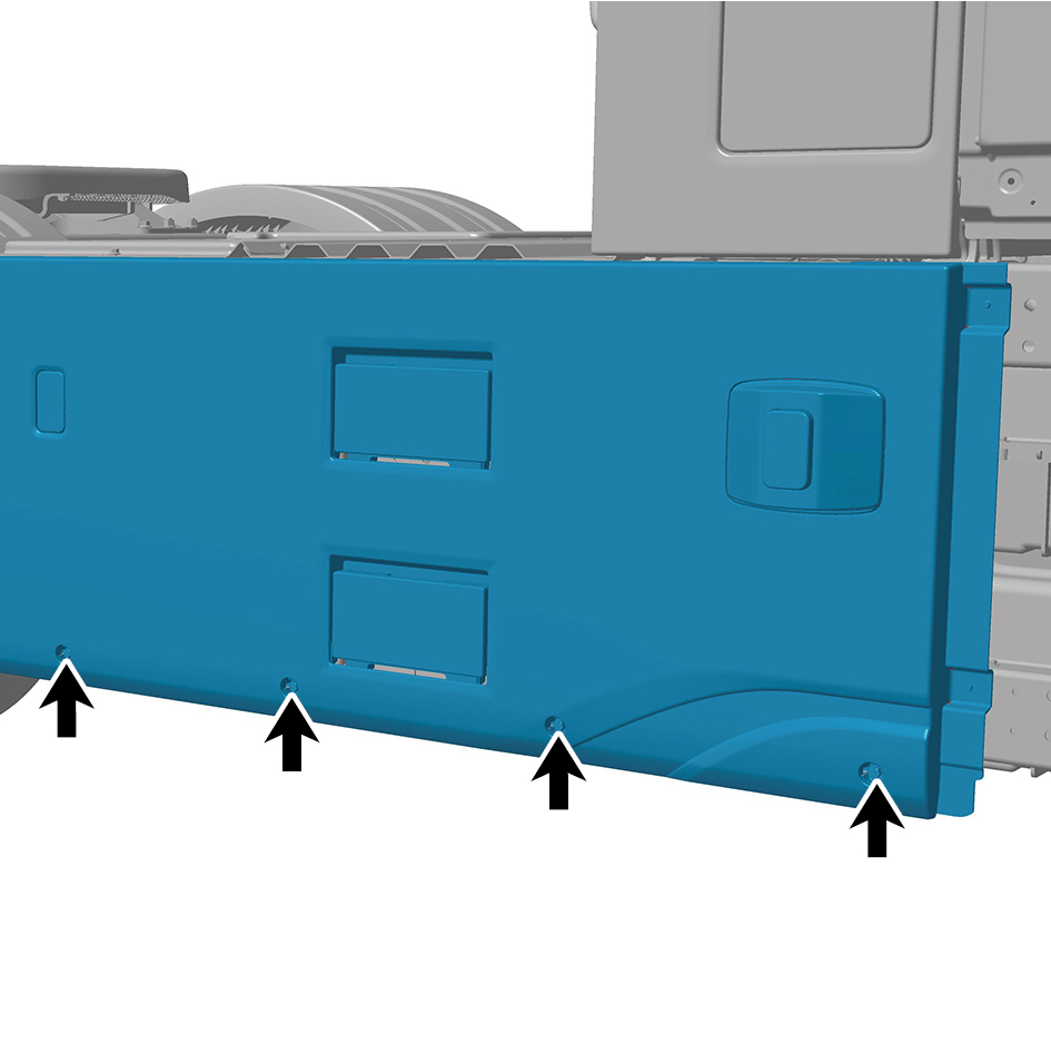
bolts of the right skirt plate assembly.
Torque: (18 ft-lb +/- 2 ft-lb) ft-lb
4
Install 2 fixing bolts of the right skirt plate assembly.
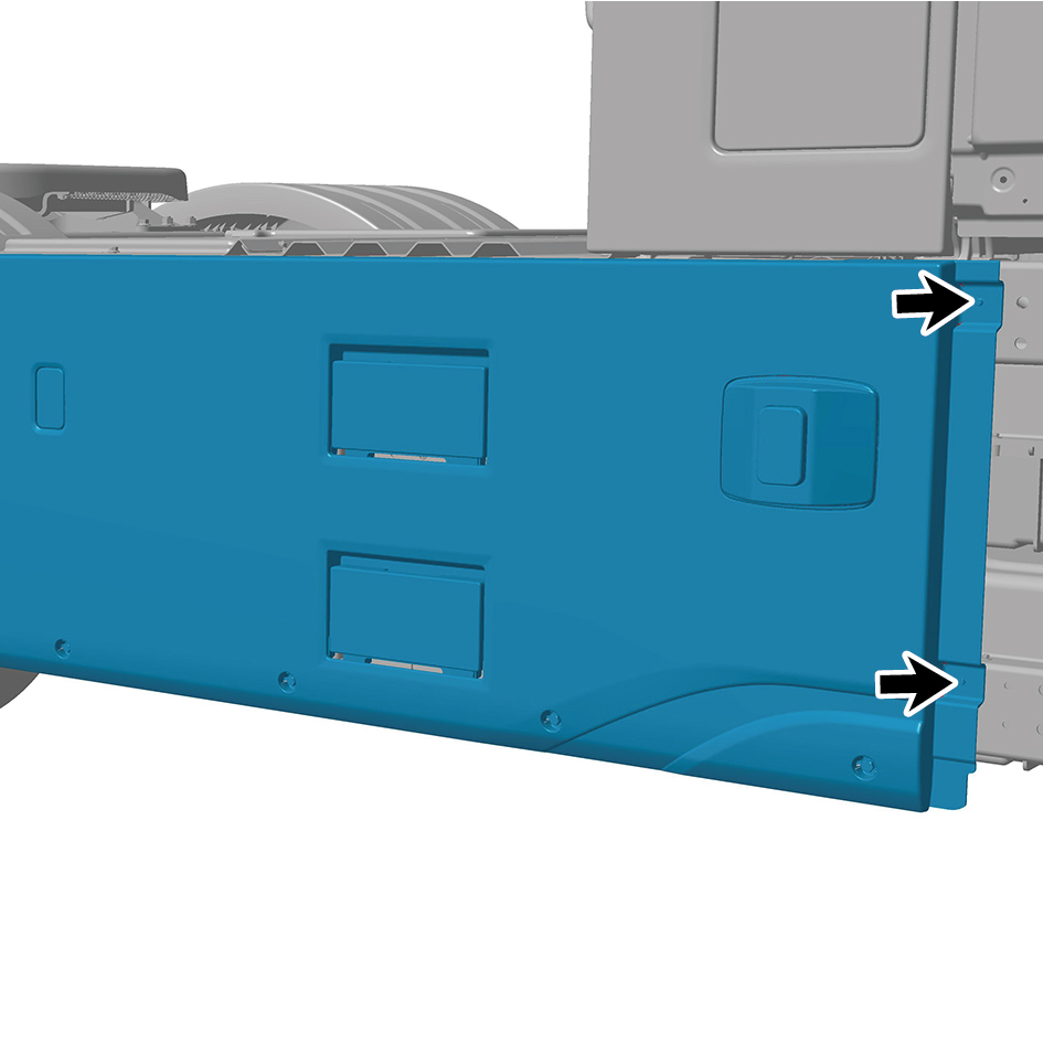
Torque: (4.5 ft-lb +/- .75 ft-lb) ft-lb
5
Install 4 protection covers.
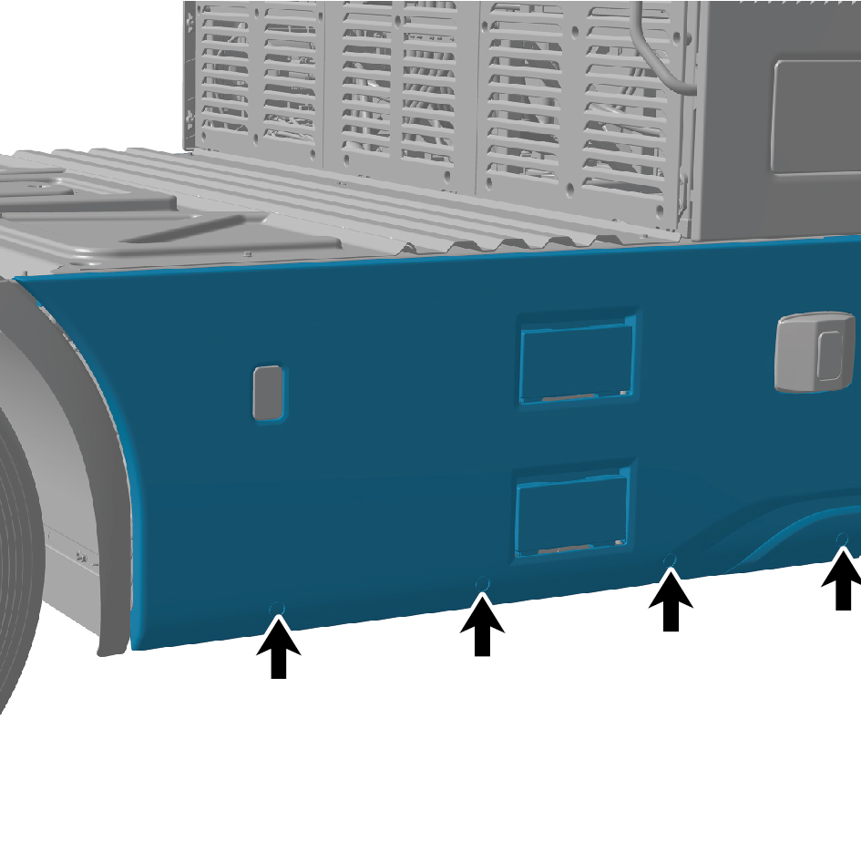
6
Install 1 fixing nut of the right skirt plate assembly.
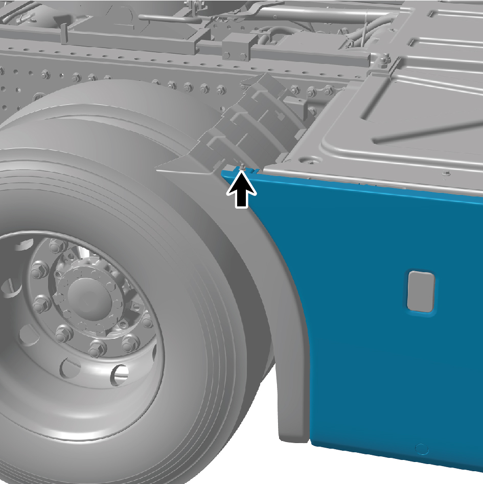
Torque:(18 ft-lb +/- 2 ft-lb) ft-lb
7
Install 5 fixing bolts of the right skirt plate assembly.
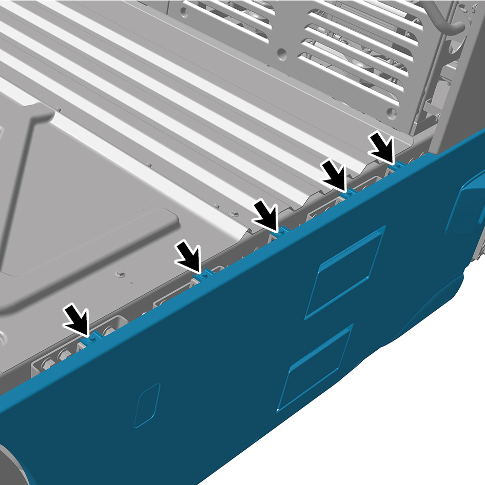
Torque:(18 ft-lb +/- 2 ft-lb) ft-lb
8
Attach the right side wall lower trim panel assembly.
9
Connect the battery negative cable.
10
Close the front flip cover plate.
11
Close the door.
6.6.3.3 Replacement of Rear Step Assembly
Removal Procedures
1
Open the door.
2
Open the front flip cover plate.
3
Disconnect the battery negative cable.
caution
power down the high-voltage system before
disconnecting the negative pole of the storage
battery.
4
Remove the right side wall lower trim panel assembly.
5
Remove the right skirt plate assembly.
6
Remove the rear step mounting base.
7
Remove 8 fixing bolts of the rear step assembly.
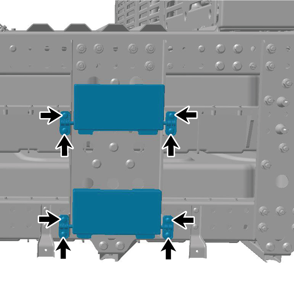
8
Remove the rear step assembly.
Installation Procedures
1
Move the rear step assembly to the mounting position.
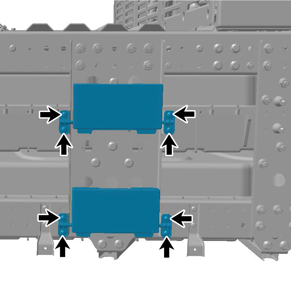
2
Install 8 fixing bolts of the rear step assembly.
Torque:(17 +/- 2) ft lbs
3
Install the rear step mounting base.
4
Install the right skirt plate assembly.
5
Attach the right side wall lower trim panel assembly.
6
Connect the battery negative cable.
7
Close the front flip cover plate.
8
Close the door.