← Back to Contents
6 Vehicle Body / 6.5 Toolbox Device | PDF pages 554-562
6.5 Toolbox Device
6.5 Toolbox Device
6.5.1 Specifications
6.5.1.1 Fastener Specifications
Range Of Torque
Fastener Specifications
Specifications
Metric System(ft-lb)
The fixing bolts connecting the toolbox
M6
6.5 ft-lb +/- .75 ft-lb
assembly to the vehicle body
6.5.2 Decomposition Diagram
6.5.2.1 Decomposition Diagram
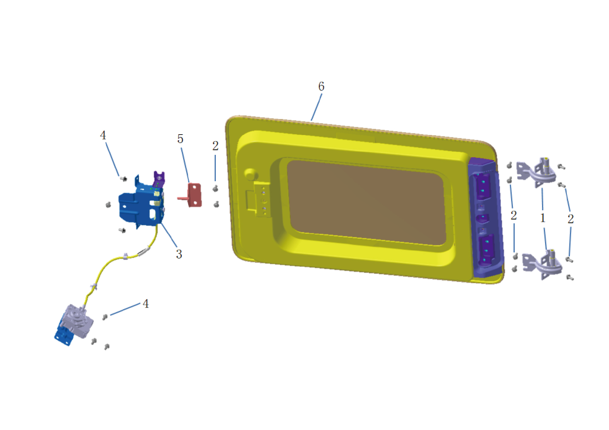
1.
Hinge-Toolbox
4.
Hexagon Flange Bolt
5.
2.
Hexagon Flange Bolt
Striker-Toolbox
3.
Lock-Toolbox
6.
Toolbox Assy
6.5.3 Dismantling and Installation
6.5.3.1 Replacement of Toolbox Lock Front End (with cable)
End (with cable)
Removal Procedures
1
Open the door.
2
Open the front flip cover plate.
3
Disconnect the battery negative cable.
caution
power down the high-voltage system before
disconnecting the negative pole of the storage
battery.
4
Open the sleeper mat assembly and disconnect one
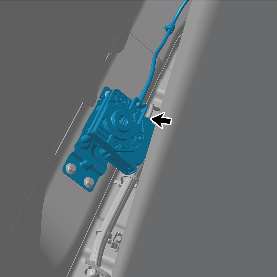
harness connector of the toolbox lock front end (with
cable).
5
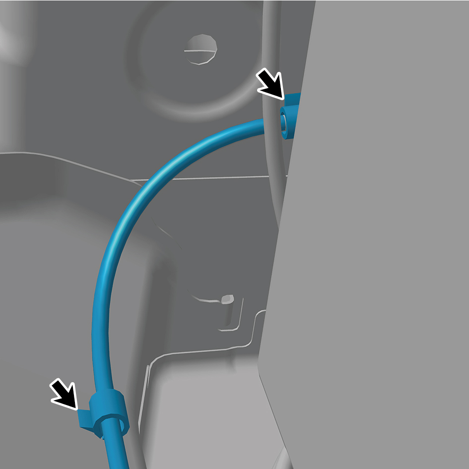
Disengage 2 fixing clips of the cable.
6
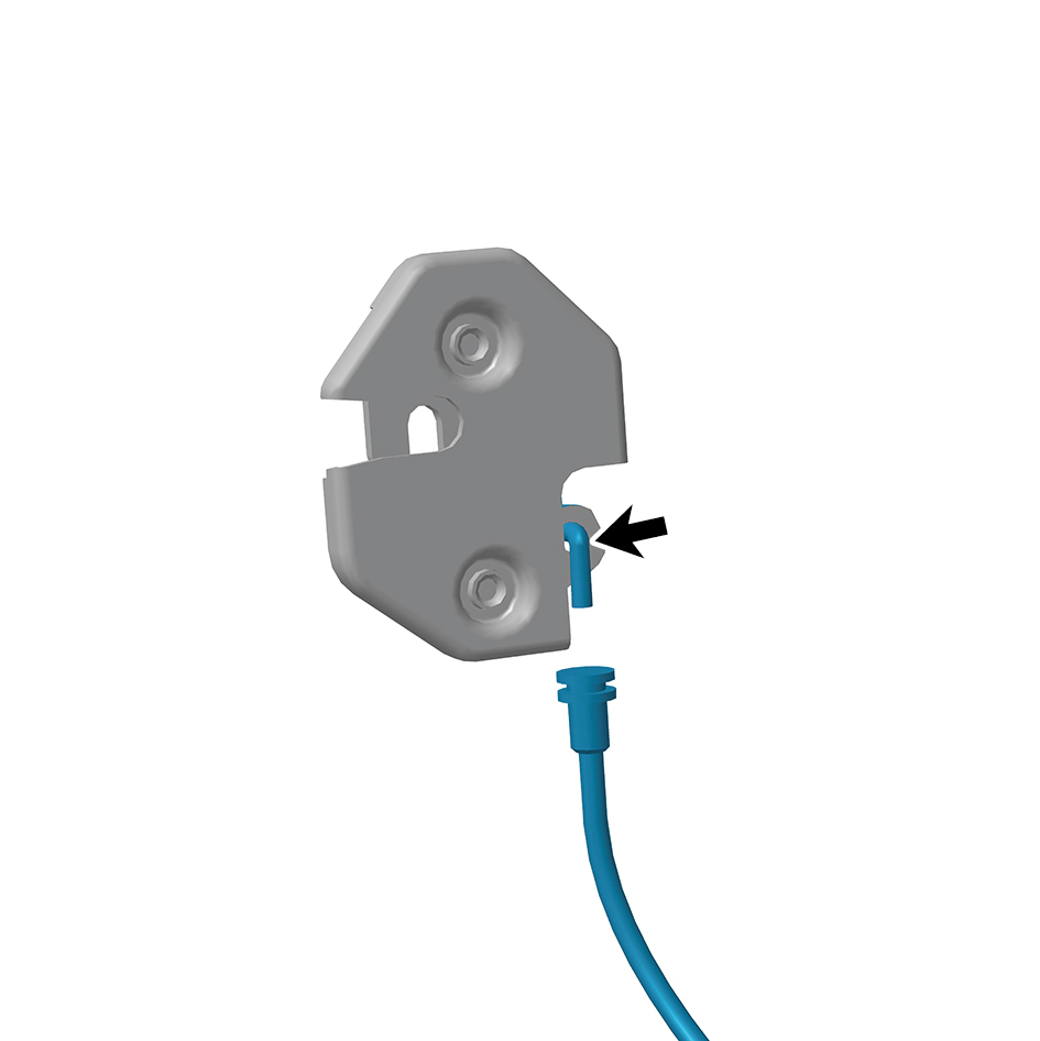
Disengage the cable.
7
Remove 3 fixing bolts of the toolbox lock front end (with
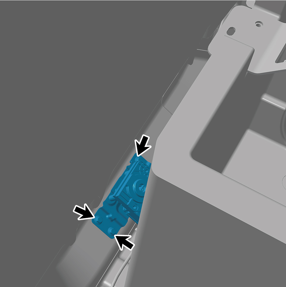
cable).
8
Remove the toolbox lock front end (with cable).
Installation Procedures
1
Move the toolbox lock front end (with cable) to the
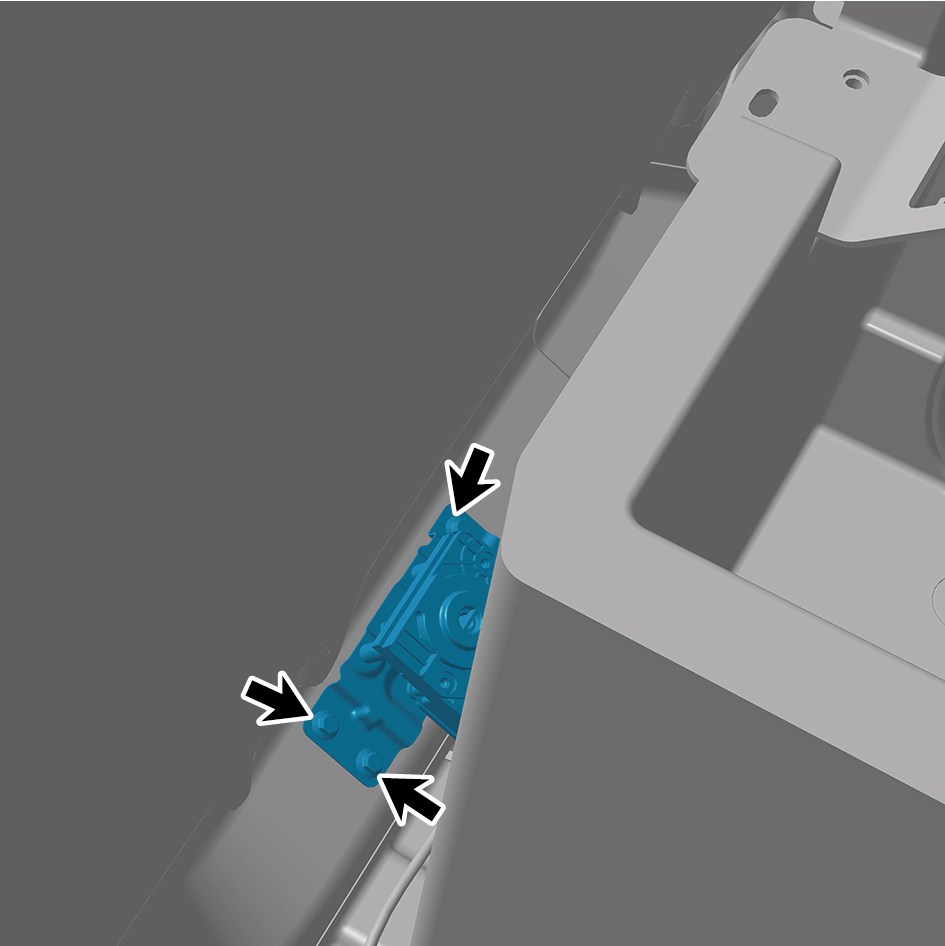
mounting position.
2
Install 3 fixing bolts of the toolbox lock front end (with
cable).
3
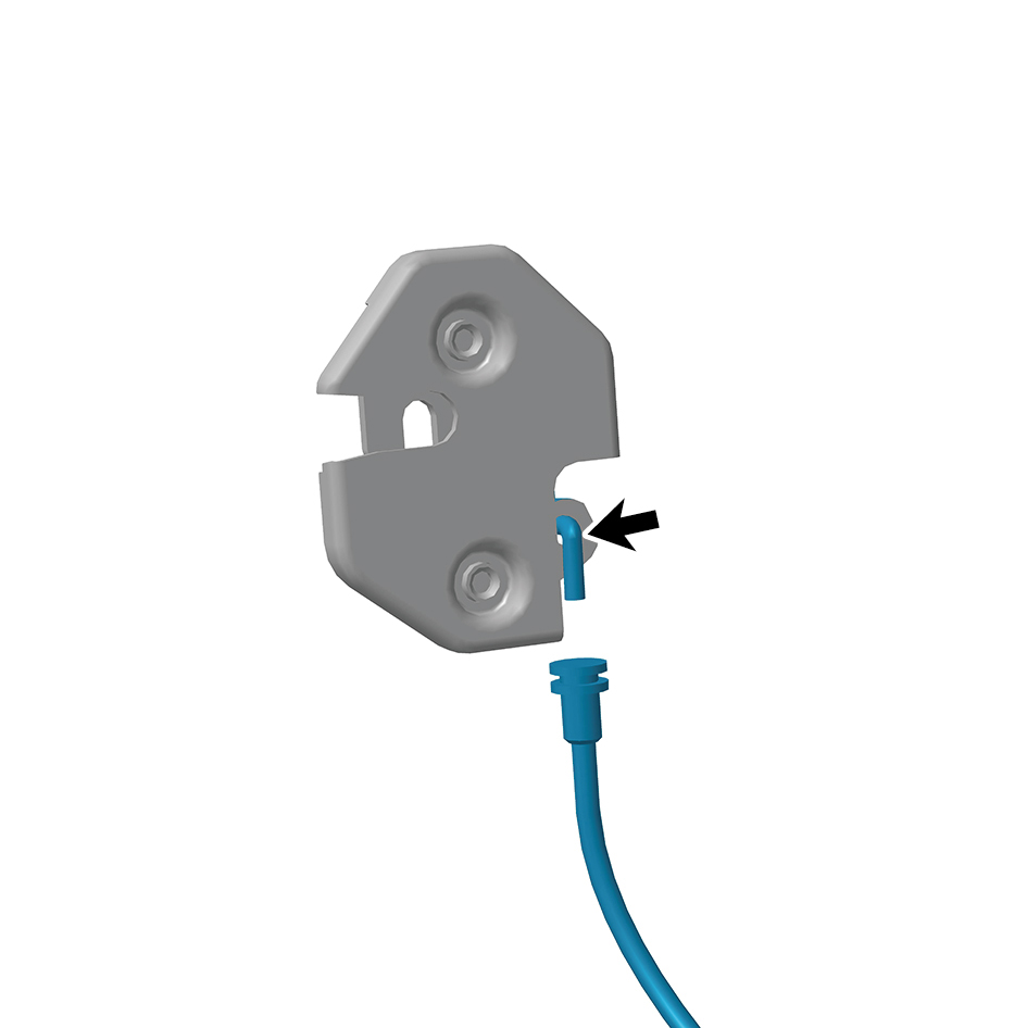
Connect the cable.
4
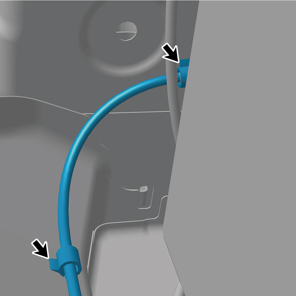
Install 2 fixing clips of the cable.
5
Connect one harness connector of the toolbox lock front
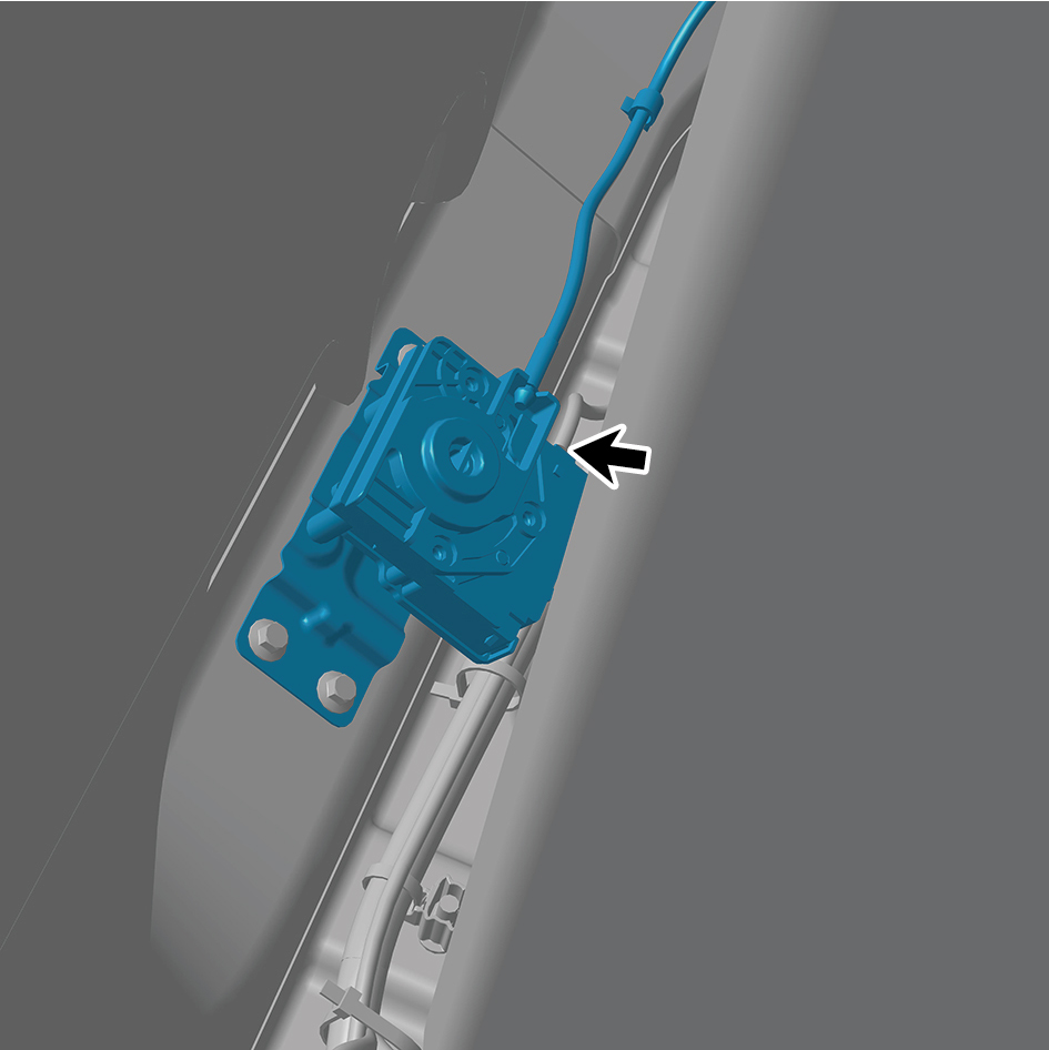
end (with cable).
caution
The harness is firmly connected following the
principal of "insert until a click is heard for
confirmation".
6
Connect the battery negative cable.
7
Close the front flip cover plate.
8
Close the door.
6.5.3.2 Replacement of Toolbox Lock Back End
End
Removal Procedures
1
Open the door.
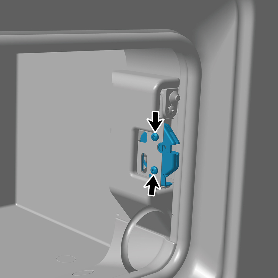
2
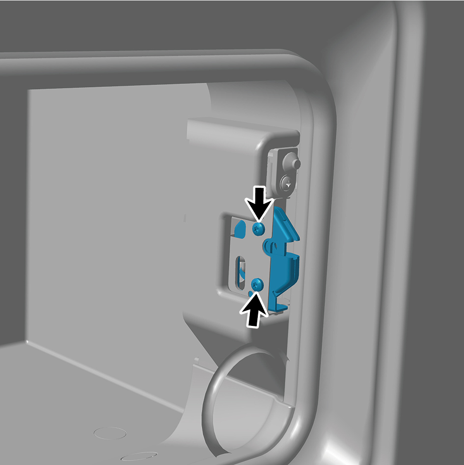
Remove 2 fixing screws of the toolbox lock back end.
3
Disengage the cable.
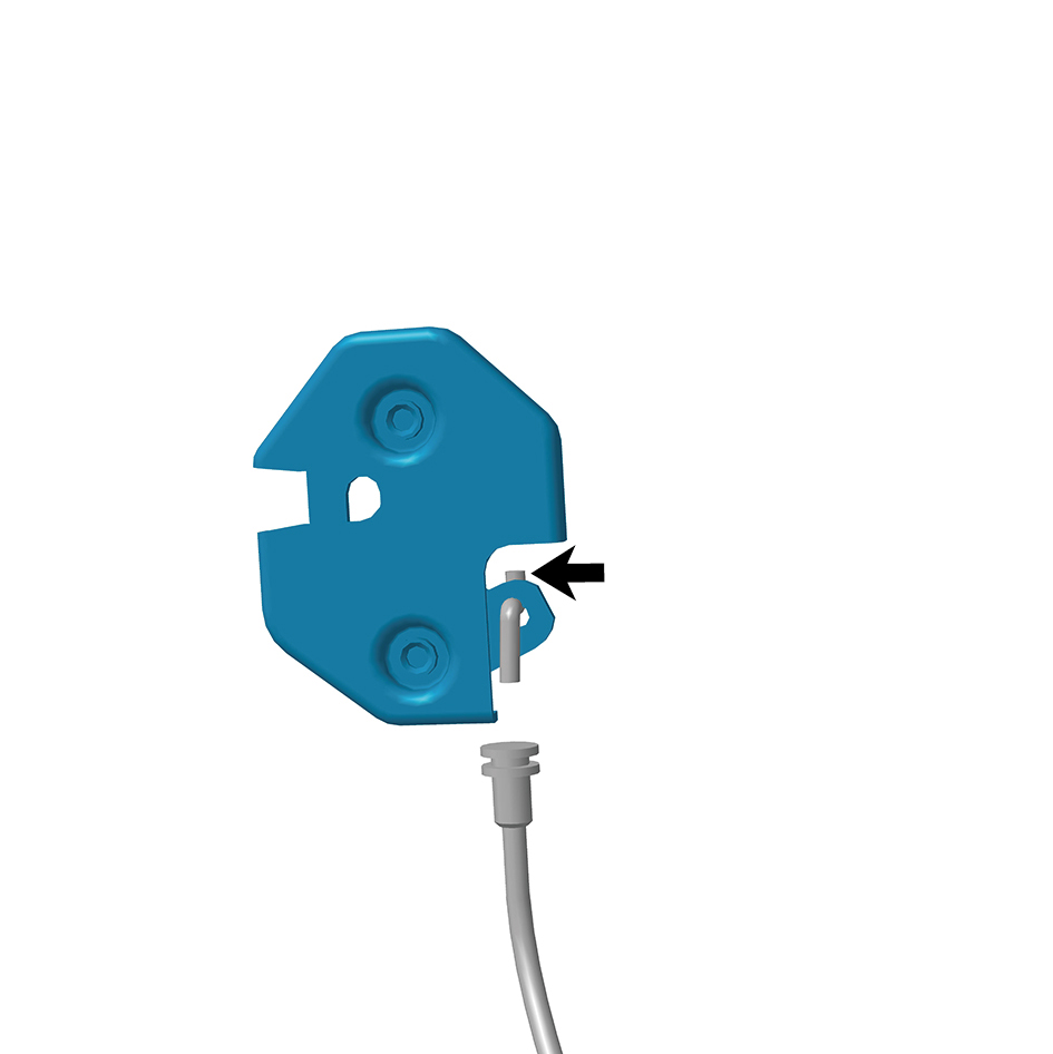
4
Remove the toolbox lock back end.
Installation Procedures
1
Move the toolbox lock back end to the mounting position.
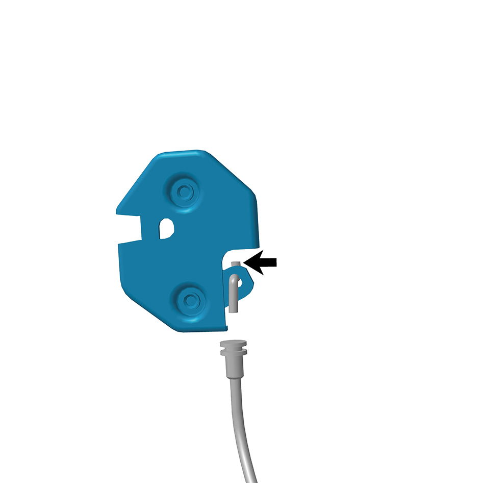
2
Connect the cable.
3
Install 2 fixing screws of the toolbox lock back end.
4
Close the door.
6.5.3.3 Replacement of Toolbox Assembly
Removal Procedures
1
Open the door.
2
Remove the toolbox lock catch.
3
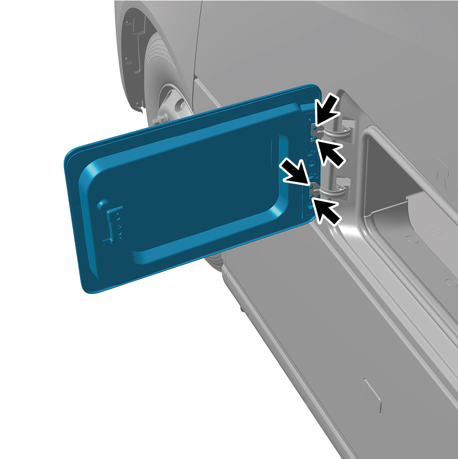
Remove 4 fixing bolts of the toolbox assembly.
4
Remove the toolbox assembly.
Installation Procedures
1
Move the toolbox assembly to the mounting position.
2
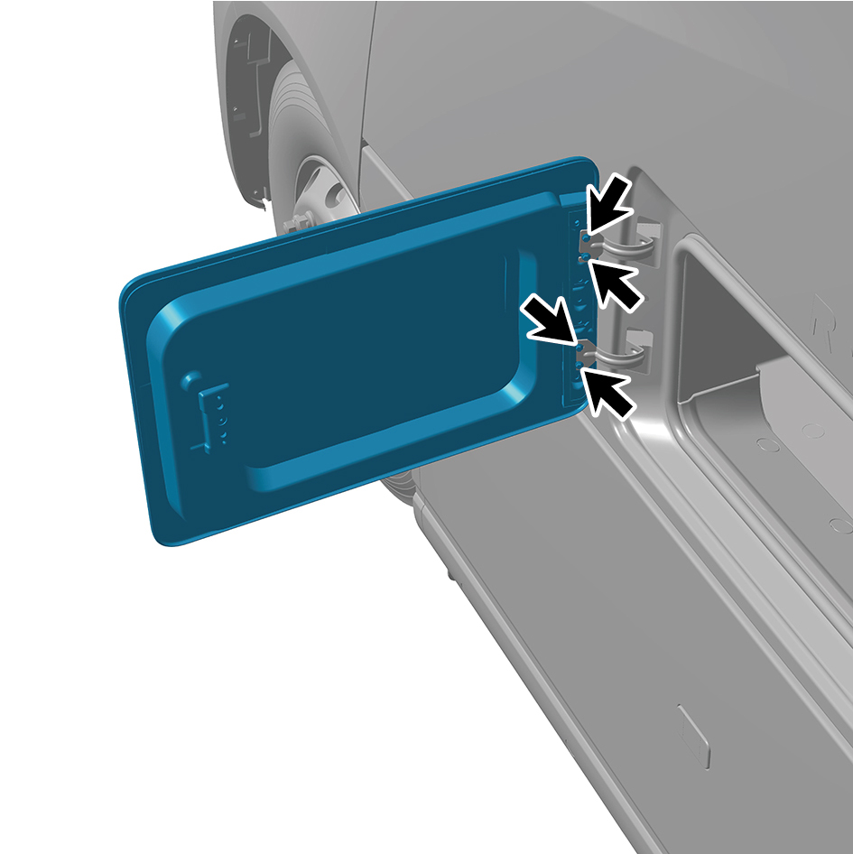
Install 4 fixing bolts of the toolbox assembly.
Torque: 6 ft-lb +/- .75 ft-lb
3
Install the toolbox lock catch.
4
Close the door.