← Back to Contents
6 Vehicle Body / 6.4 Body-in-White Device | PDF pages 522-553
6.4 Body-in-White Device
6.4 Body-in-White Device
6.4.1 Specifications
6.4.1.1 Fastener Specifications
Range Of Torque
Fastener Specifications
Specifications
Metric System(N·m)
The fixing bolts connecting the white
M16
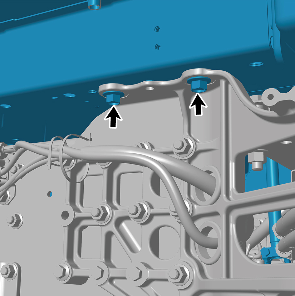
310 ± 10 (Kexin 1262)
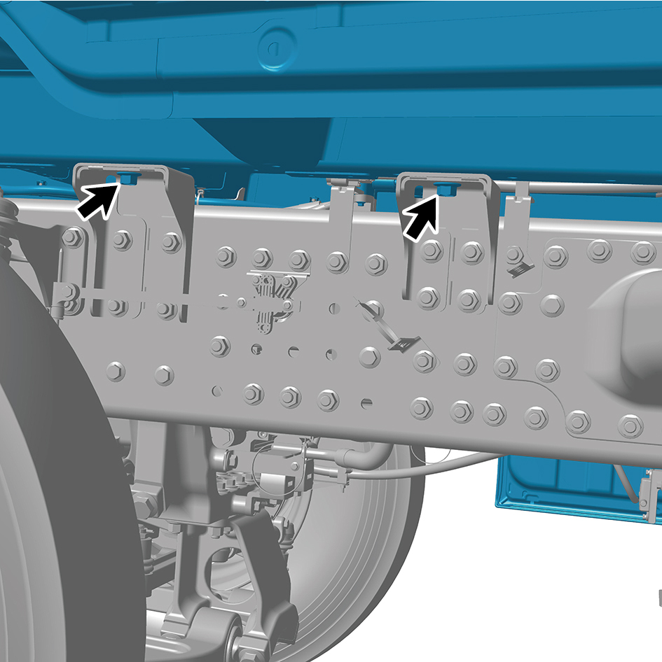
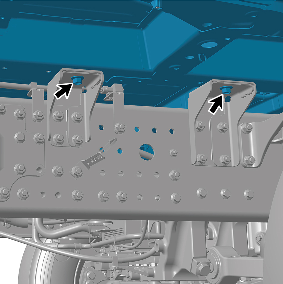
body assembly and the front connecting
beam
The fixing bolts connecting the white
M16
310 ± 10 (Kexin 1262)
body assembly and the suspension
bracket three
assemblies
The fixing bolts connecting the white
M16
310 ± 10 (Kexin 1262)
body assembly and the suspension
bracket two
assemblies
The fixing bolts connecting the white
body assembly and the air conditioning
M6
9±1
pipeline
The fixing bolt of the grounding wire
harness connecting the white body
M8
25±3
assembly and the frame
assembly
6.4.2 Decomposition Diagram
6.4.2.1 Decomposition Diagram
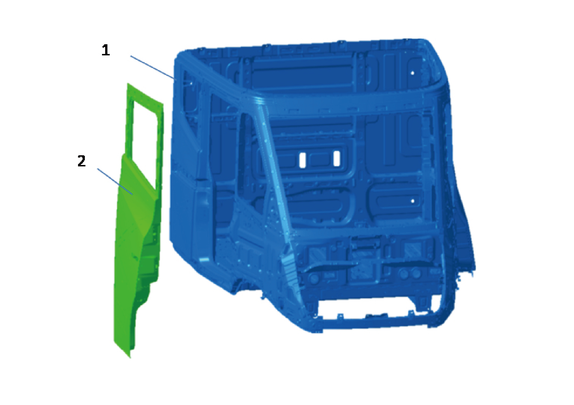
1.
2.
Slide Door Assy
Slide Door Assy
6.4.3 Sheet Metal and Painting
1. Scrape coating of poly-putty base.
6.4.3.1 Colored Paint Information
2. Grinding of poly-putty base.
Supplier
S/N
Color
3. Dust blowing, degreasing, cleaning.
Shanghai Kinlita Chemical
4. Scrape coating of fill-in putty.
Icy snow-white
1
Co., Ltd.
5. Surface sanding of old paint film.
6.4.3.2 Sheet Metal
6. Cleaning, degreasing, and covering of unpainted areas.
Removal
1. Remove all relevant panels and components related to
replacement parts.
2. Remove the sealant and anti-corrosion materials if
necessary.
3. Locate, mark, and drill all factory solder joints connecting
the components to be replaced.
4. Remove damaged components to be replaced.
5. Remove residual materials.
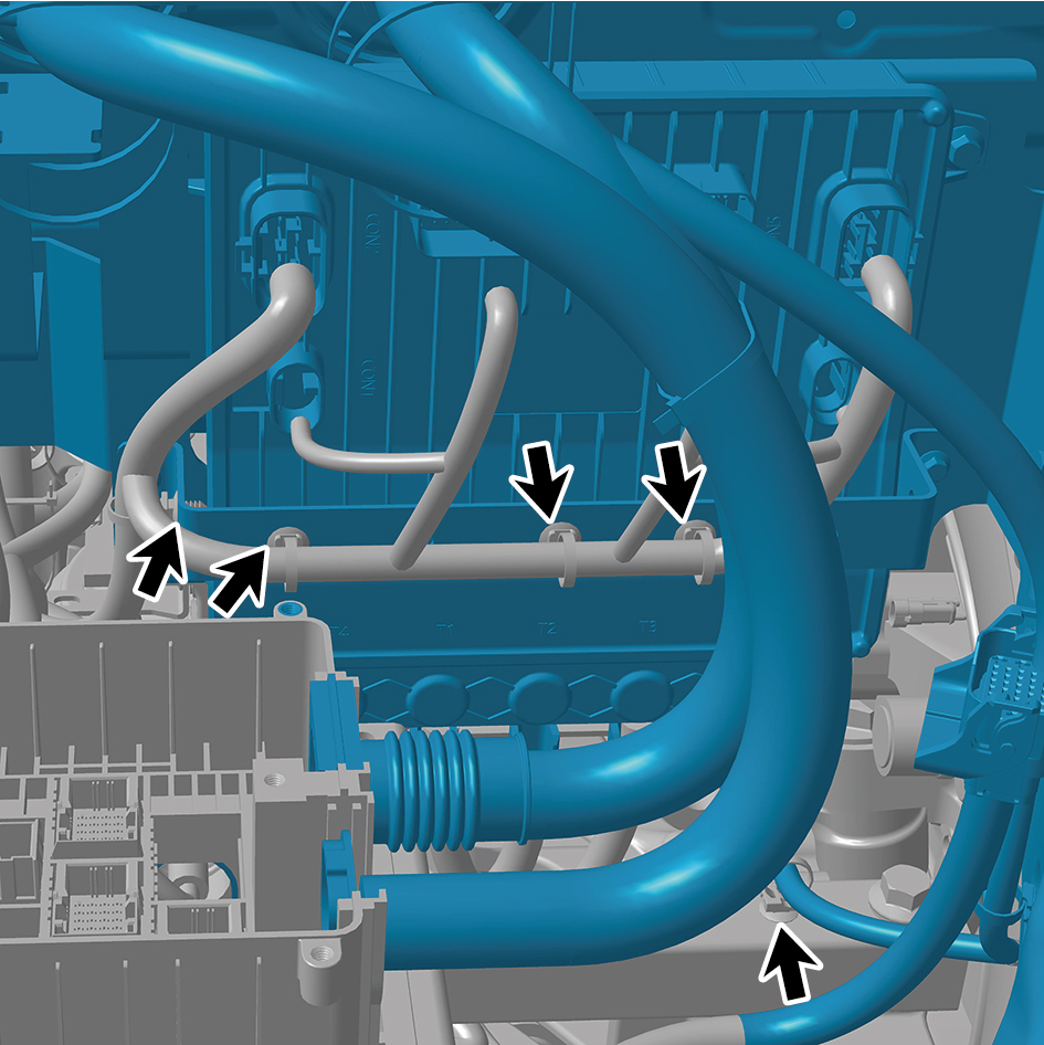
Installation
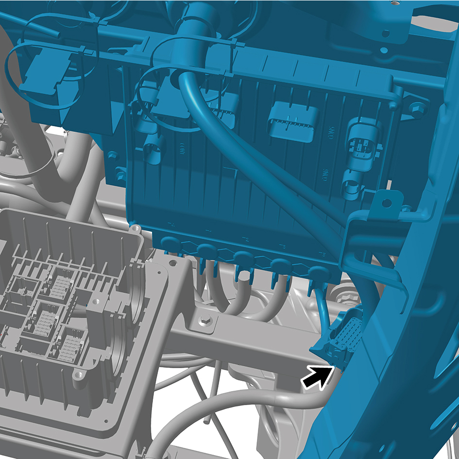
1. Pre-treat the mating surface as necessary.
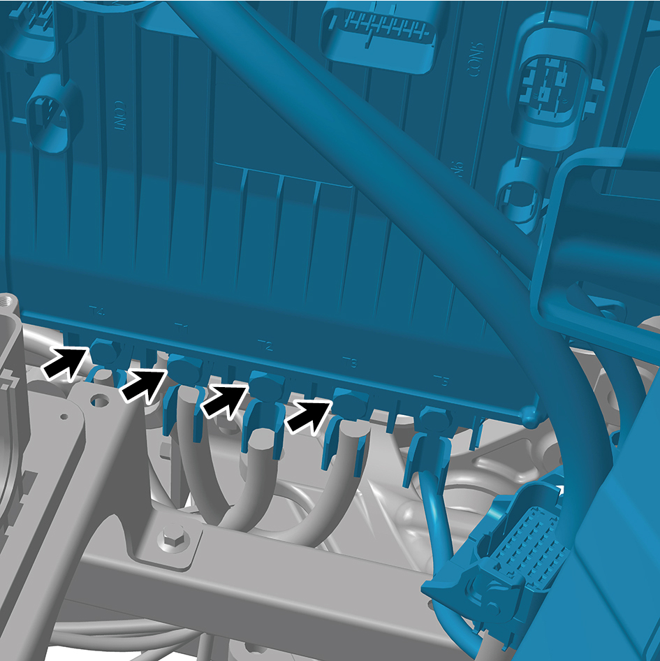
2. Select the correct welding method based on the welding
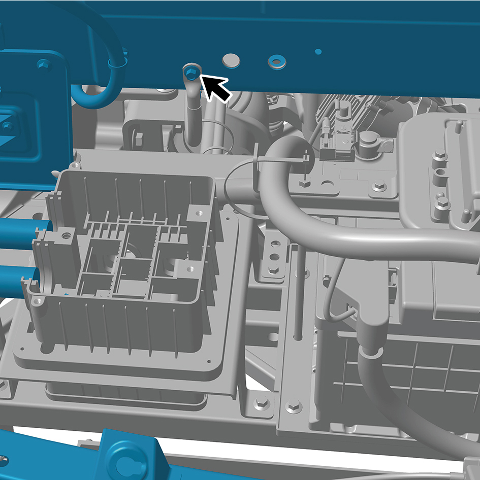
form of the original vehicle. Employ shielded welding in
areas where resistance welding is inconvenient. If plug
welding is chosen, drill holes for plug welding seams on the
new part, and determine the diameter and spacing of the
plug welding holes based on the original solder joints.
3. Temporarily place the new part on the vehicle.
4. Assemble and fix the new part with a correction support
(correctly position the maintenance panel).
5. Regularly measure the position of the new part to ensure its
assembly dimensions are correct.
6. Perform corresponding welding.
7. Clean all welding surfaces.
8. Apply primer.
9. Apply sealant and anti-corrosion materials if necessary.
10. Install all relevant panels and components.
6.4.3.3 Painting
Painting Procedure
The painting procedure for rigid surfaces after sheet metal
repair is similar to the painting process for rigid surfaces,
except that the following steps are added after grinding the
primer and before applying the base coat:
6.4.4 Dismantling and Installation
6.4.4.1 Replacement of BIW Assembly
Removal Procedures
1
Release air pressure from the brake system.
2
Open the door.
3
Open the front flip cover plate.
4
Disconnect the battery negative cable.
5
Perform power-off of high voltage system.
6
Recycle A/C refrigerant.
7
Jack the front end of the vehicle.
8
Drain coolant from the power system.
9
Drain coolant from battery thermal management system.
10
Remove the left front wheel housing body.
11
Remove the right front wheel housing body.
12
Remove the left front wheel housing rear body.
13
Remove the right front wheel housing rear body.
14
Remove the roof deflector body.
15
Remove the roof deflector middle bracket.
16
Remove the left deflector upper body.
17
Remove the roof deflector mounting bracket.
18
Remove the left deflector lower body.
19
Remove the upper deflector mounting bracket.
20
Remove the right deflector upper body.
21
Remove the right deflector lower body.
22
Remove the back integrated bracket side cover plate
assembly (left).
23
Remove the back integrated bracket side cover plate
assembly (right).
24
Remove the back integrated bracket middle cover plate
assembly.
25
Remove the back integrated bracket upper cover plate
filler cap.
26
Remove the back integrated bracket upper cover plate.
27
Remove the engine compartment trim panel body.
28
Remove the through-type lamp.
29
Remove the front MMW radar shield.
30
Remove the forward MMW radar.
31
Remove the front MMW radar adapter bracket.
32
Remove the left cover plate of the corner radar.
33
Remove the right cover plate of the corner radar.
34
Remove the front bumper assembly.
35
Remove the left physical exterior rearview mirror
assembly.
36
Remove the primary wiper arm blade assembly (nozzle
and hose).
37
Remove the front windshield cover plate assembly.
38
Remove the left fender trim strip.
39
Remove the left fender assembly.
40
Remove the left front combination lamp.
41
Remove the left headlamp.
42
Remove the left headlamp bracket.
43
Remove the right triangular cover plate assembly.
44
Remove the right fender trim strip.
45
Remove the right fender assembly.
46
Remove the right front combination lamp.
47
Remove the right headlamp.
48
Remove the right headlamp bracket.
49
Remove the left side wall lower trim panel assembly.
50
Remove the side wall upper mounting bracket assembly
2.
51
Remove the left side wall mounting bracket 1.
52
Remove the left side wall mounting bracket 2.
53
Remove the left side wall lower trim panel mounting frame
assembly.
54
Remove the lamp (upper).
55
Remove the lamp (lower).
56
Remove the boarding step body assembly.
57
Remove the boarding step bracket.
58
Remove the upper wheel housing connecting bracket.
59
Remove the lower wheel housing connecting bracket.
60
Remove the boarding step tubular beam.
61
Remove the frame main truss.
62
Remove 5 fixing bolts of Left Junction Box cover plate,
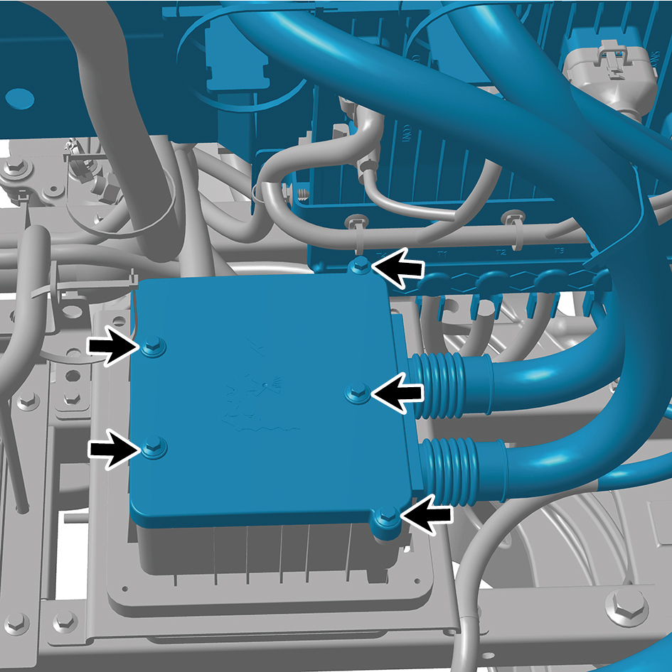
and open Left Junction Box.
63
Disconnect 6 harness connectors of Left Junction Box.
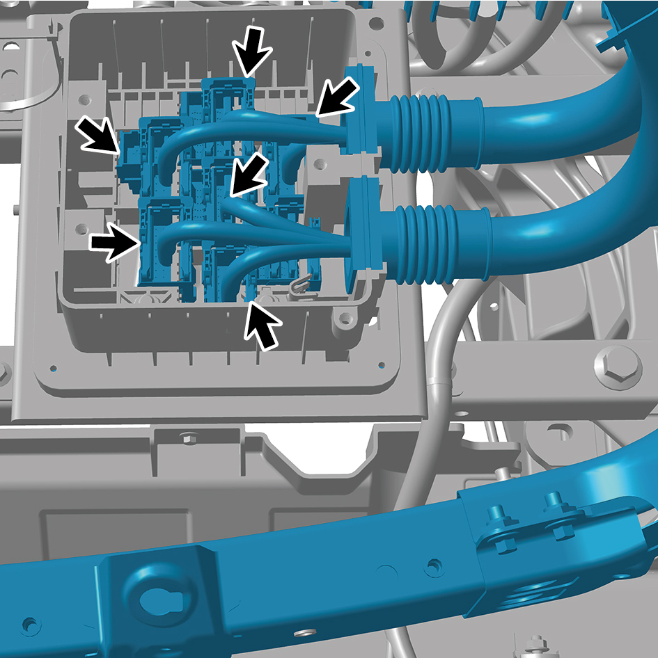
64
Remove 1 fixing nut of Left Junction Box ground harness,
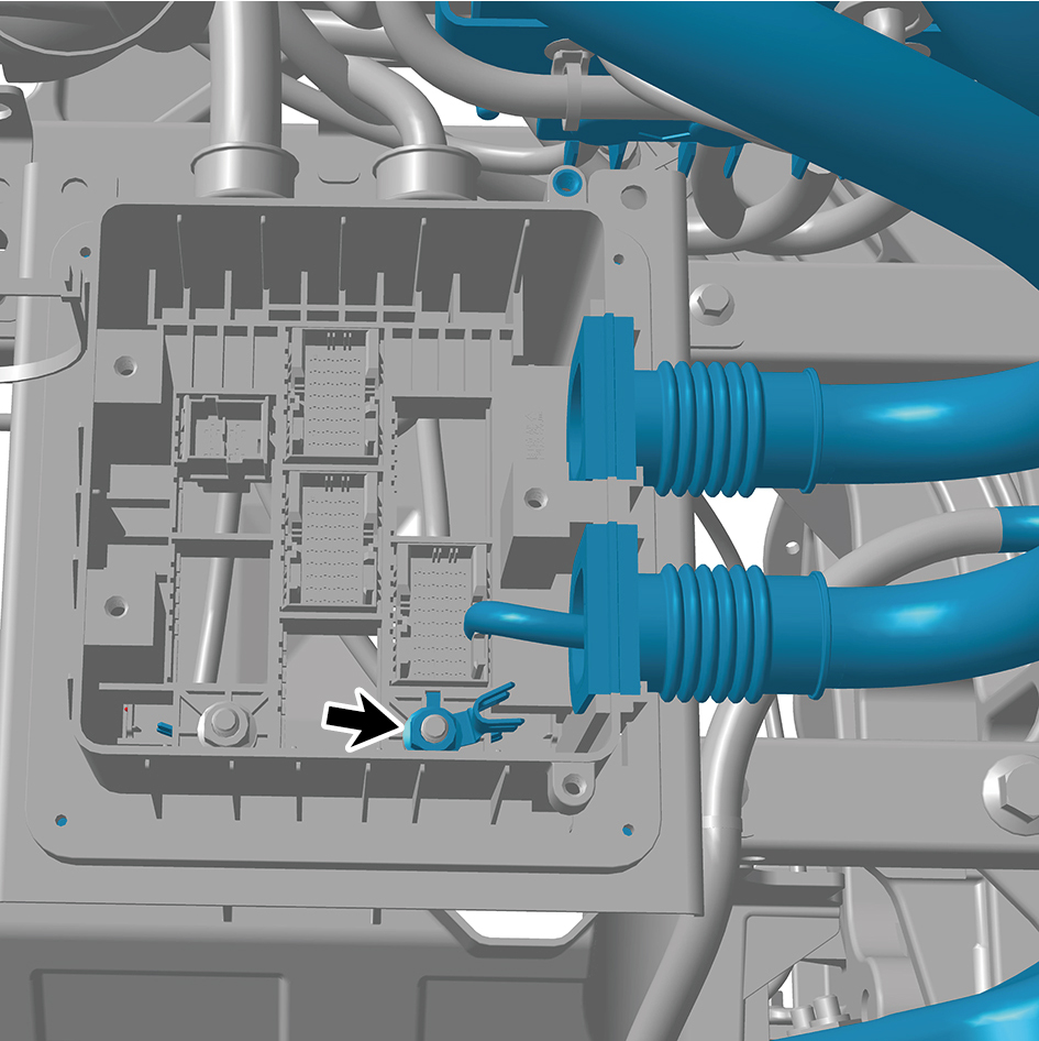
and disconnect Left Junction Box ground harness.
65
Remove 5 fixing bolts of Right Junction Box cover plate,
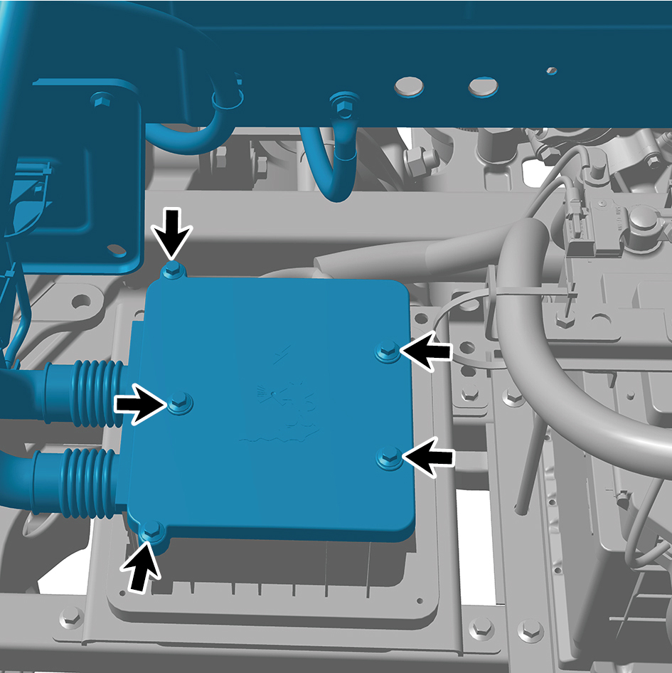
and open Right Junction Box.
66
Disconnect 6 harness connectors of Right Junction Box.
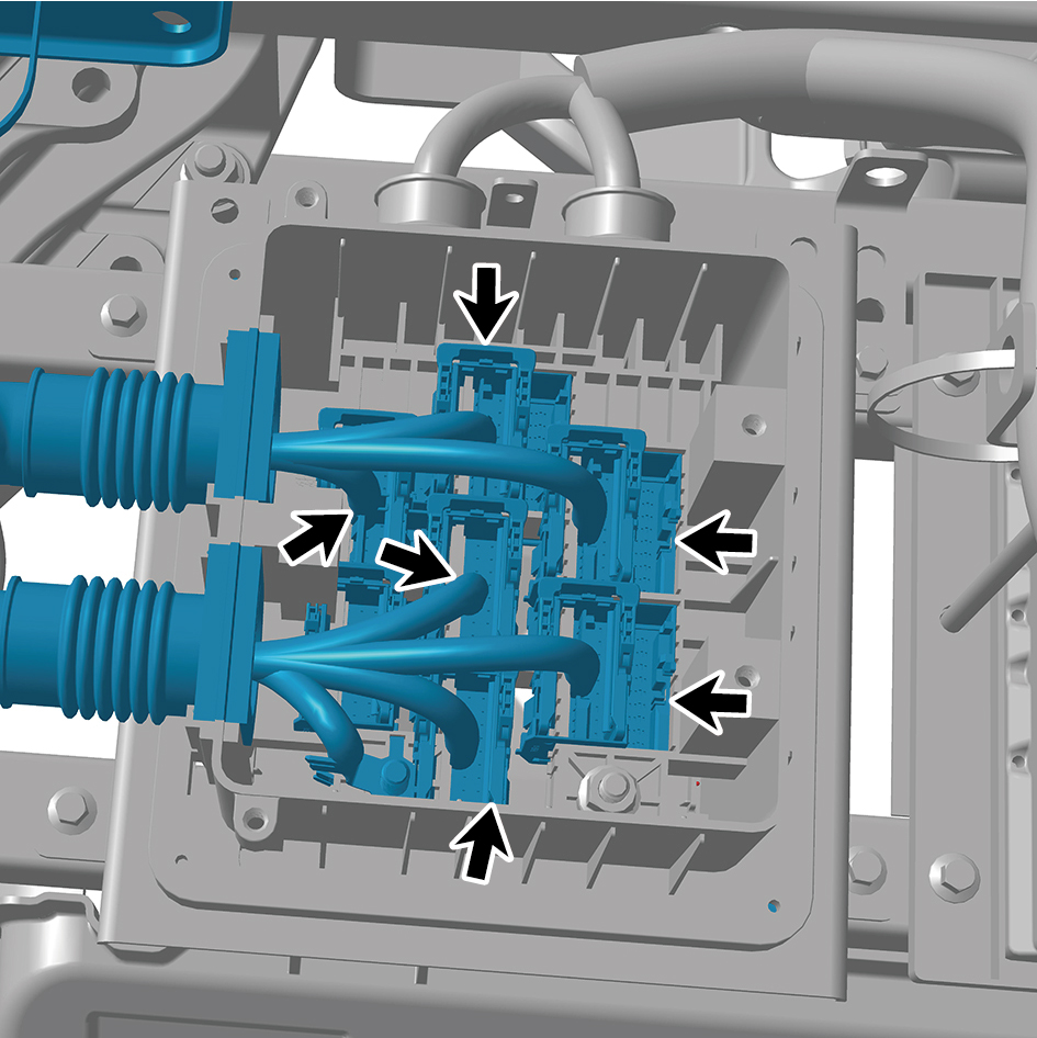
67
Remove 1 fixing nut of Right Junction Box ground
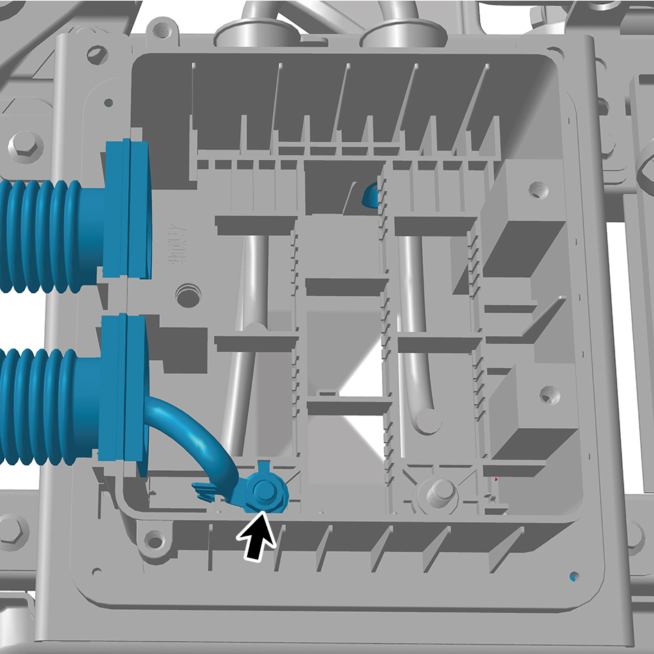
harness, and disconnect Right Junction Box ground
harness.
68
Disconnect 6 harness connectors of the SJB_UN.
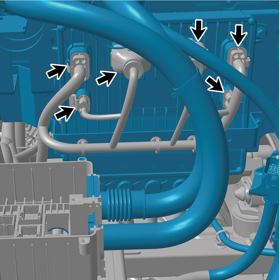
69
Disengage 5 harness clips.
70
Disconnect 1 harness connector.
71
Remove the 4 fixing bolts of the harness.
72
Remove 1 fixing bolt of the BIW assembly ground harness
(at Right Junction Box).
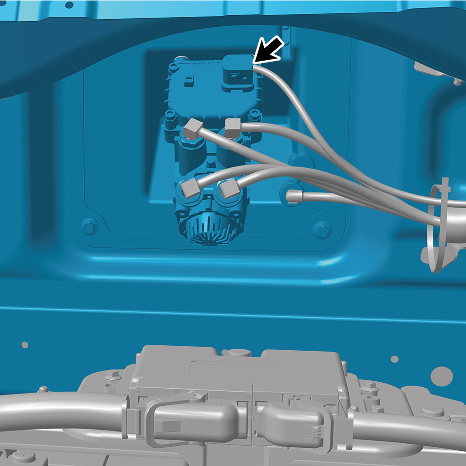
73
Disconnect 1 harness connector.
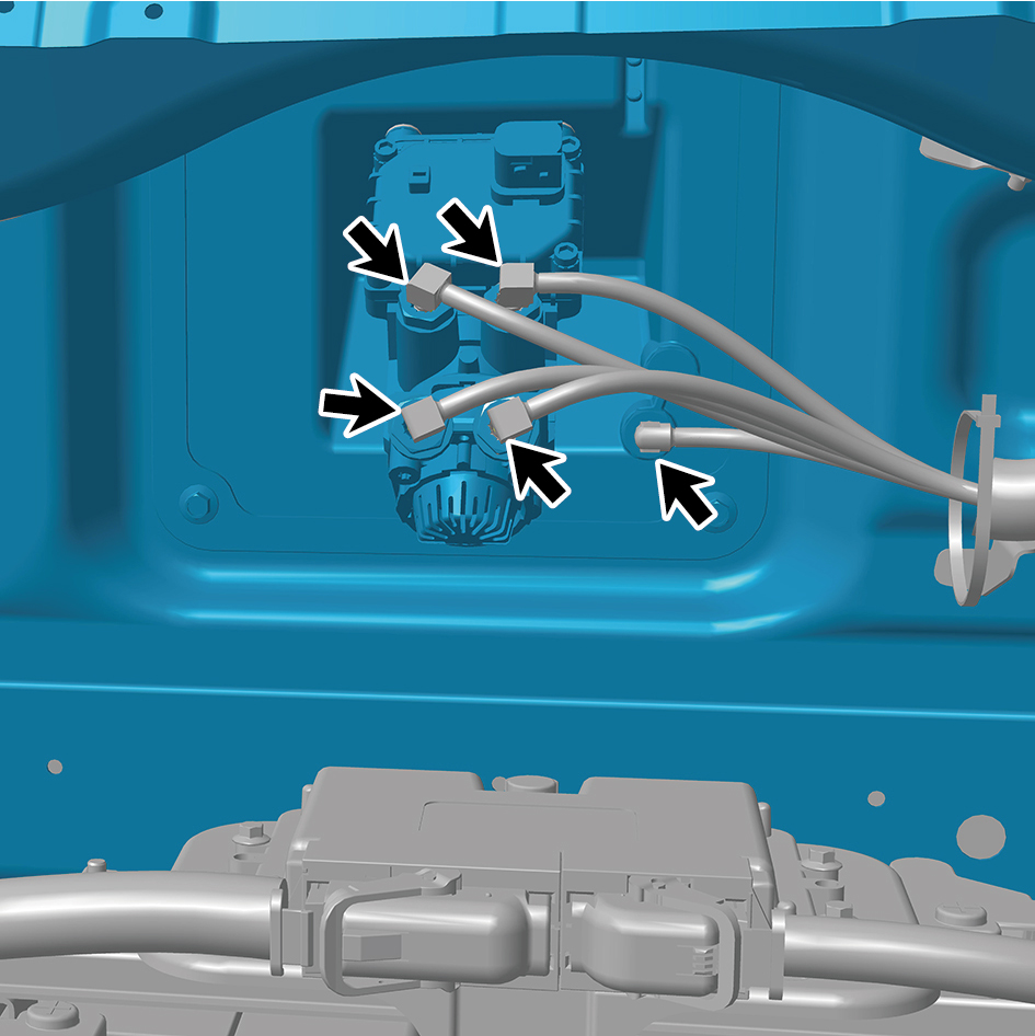
74
Disconnect 5 brake air pipes of the brake signal
transmitter.
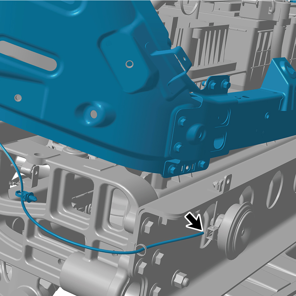
75
Disconnect 1 harness connector of the electric horn - high
pitch.
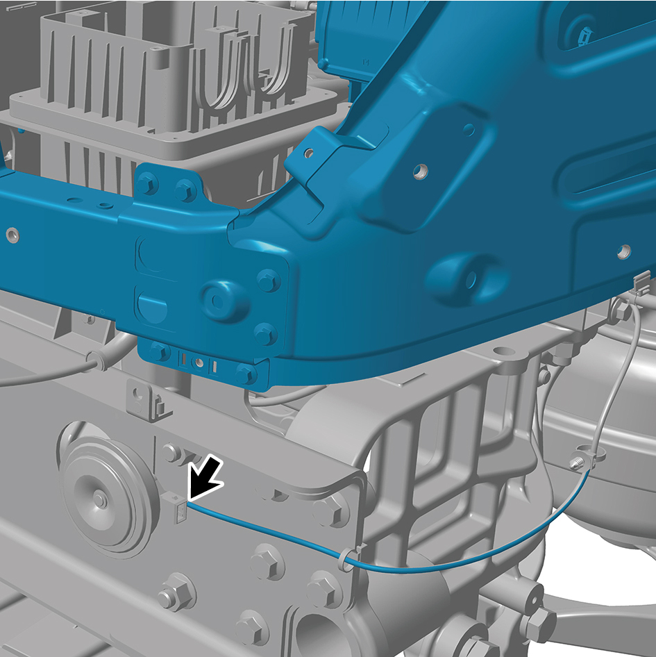
76
Disconnect 1 harness connector of the electric horn - low
pitch.
77
Remove 1 fixing bolt of the steering drive shaft, and
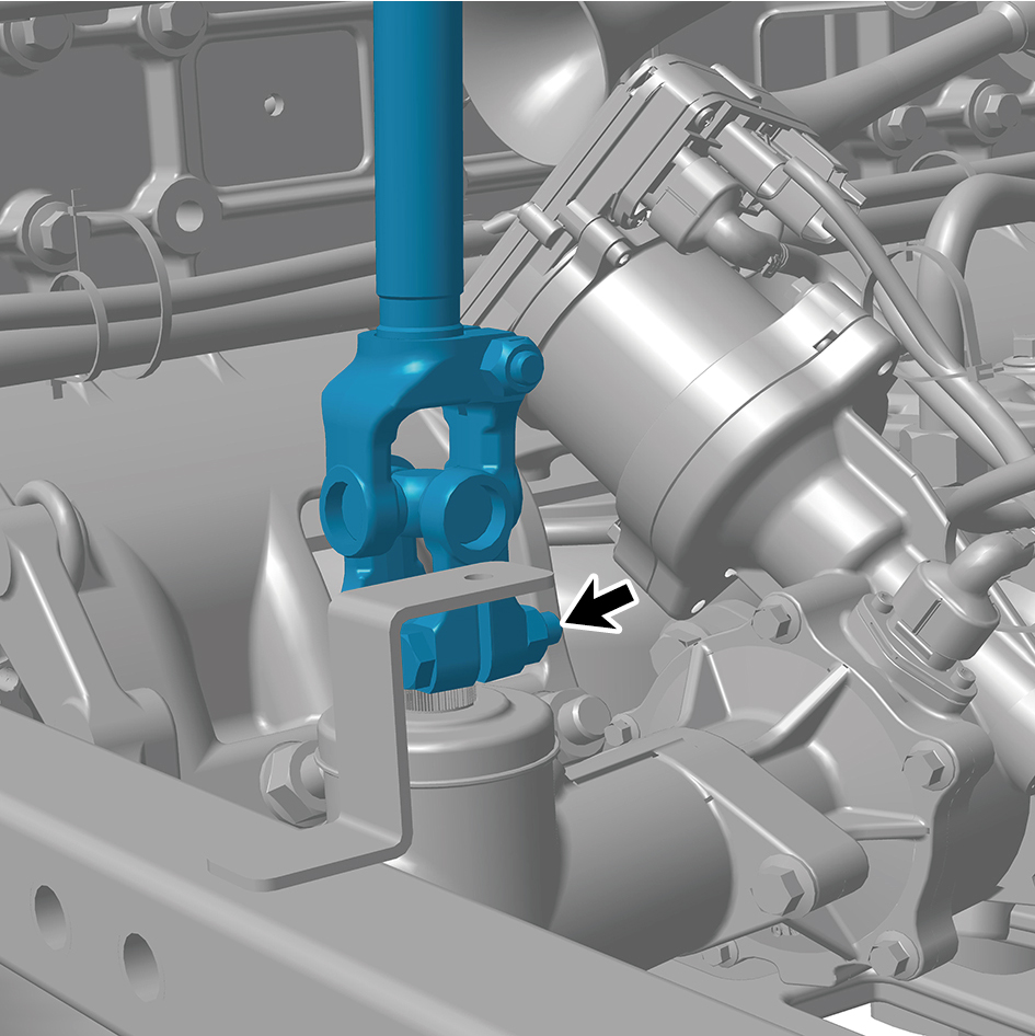
disconnect the steering drive shaft from the integrated
EHPS assembly.
78
Remove 1 fixing bolt of the A/C high/low pressure pipe
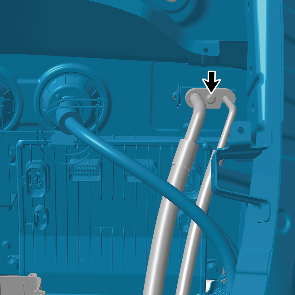
(left), and disconnect the A/C high/low pressure pipe (left).
79
Remove 1 fixing bolt of the A/C high/low pressure pipe
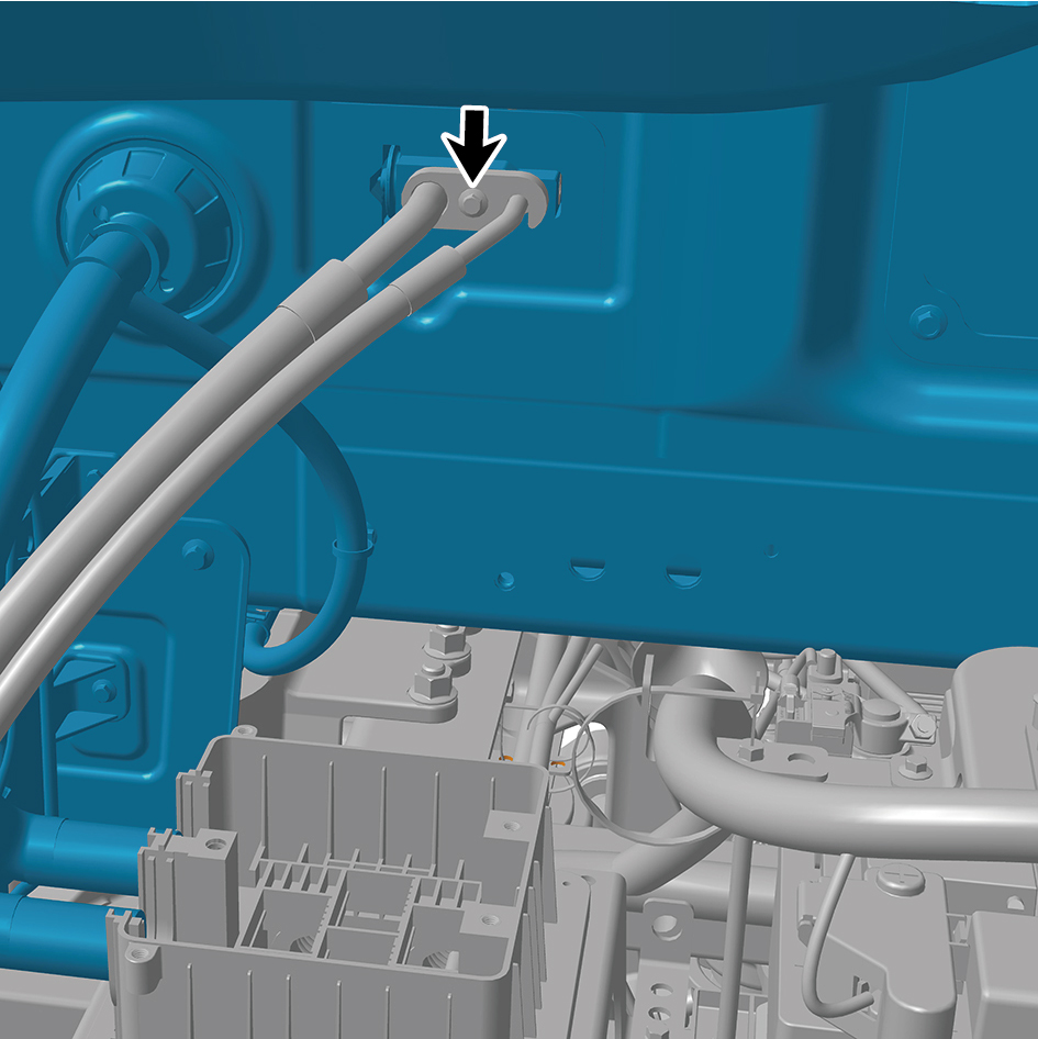
(right), and disconnect the A/C high/low pressure pipe
(right).
80
Disconnect 1 high voltage harness connector at the
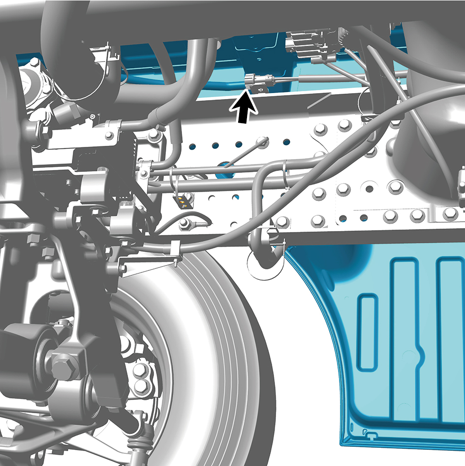
bottom of the BIW assembly.
81
Disconnect 1 high voltage harness connector at the
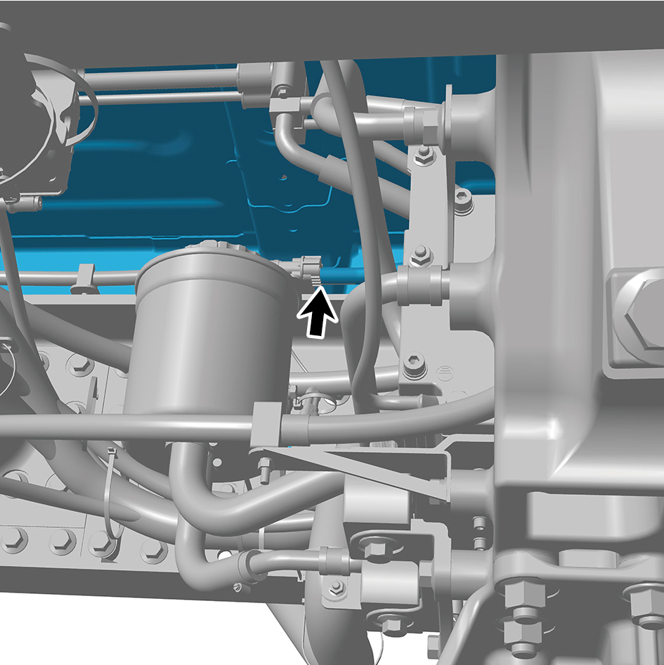
bottom of the BIW assembly.
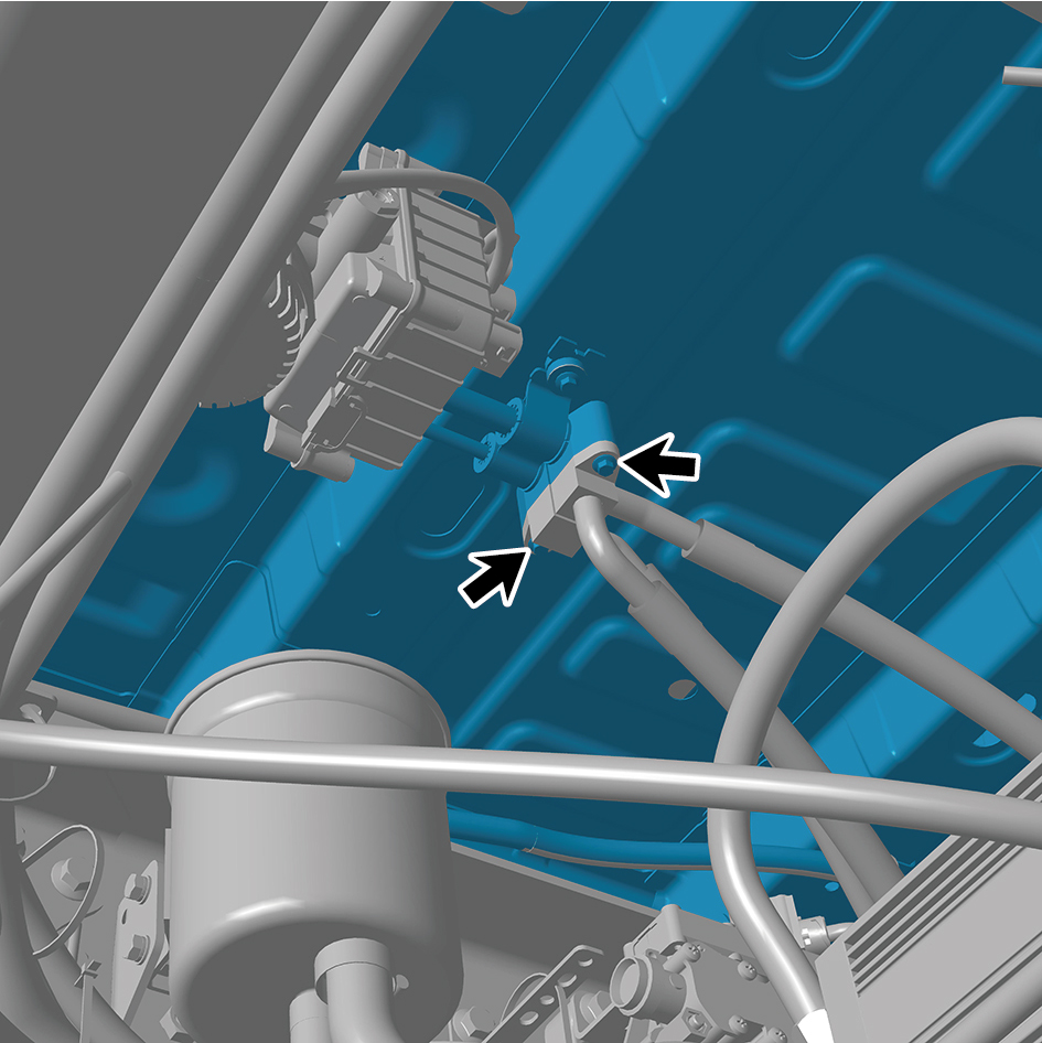
82
Remove 2 fixing bolts, and disconnect the A/C pipeline at
the bottom of the BIW assembly.
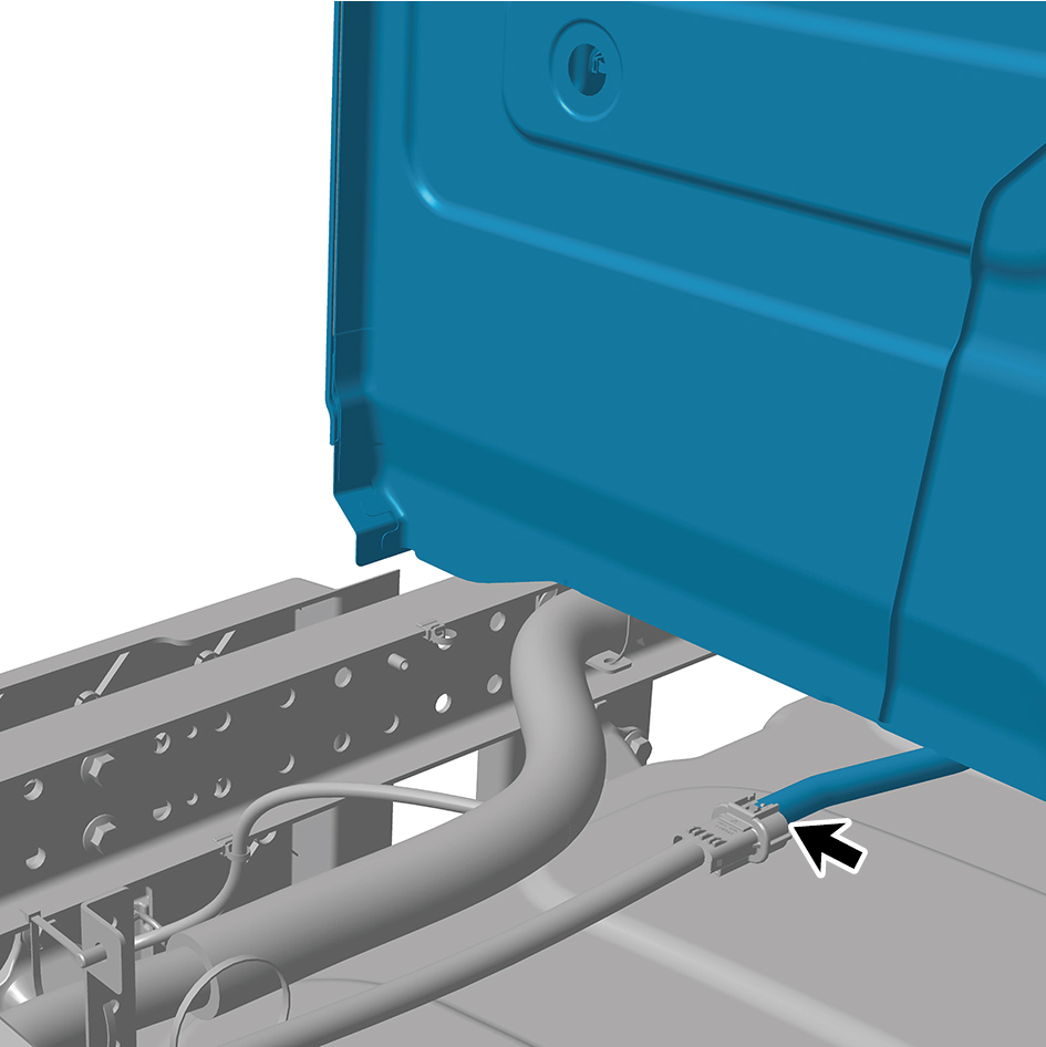
83
Disconnect 1 high voltage harness connector at the rear
of the BIW assembly.
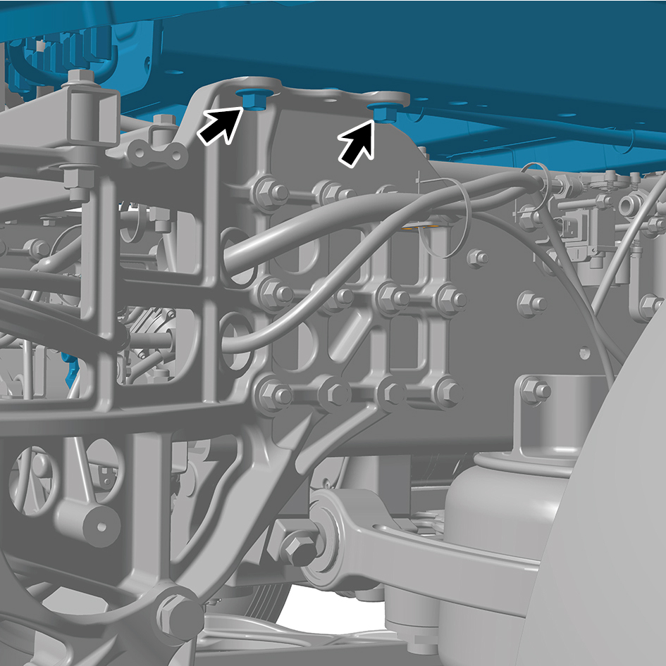
84
Remove 2 fixing bolts connecting the BIW assembly to the
left front joint beam.
85
Remove 2 fixing bolts connecting the BIW assembly to the
mounting bracket II and III assembly.
86
Remove 2 fixing bolts connecting the BIW assembly to the
mounting bracket II and III assembly.
87
Remove 2 fixing bolts connecting the BIW assembly to the
right front joint beam.
88
Disconnect the strap clip of the BIW assembly front wall
harness, clean the harness, and separate it from the cab.
89
Pre-install the cab lifting tool.
90
Remove 2 bolt (left upper) of the rear wall mounting plate
(left).
91
Remove 2 bolt (right upper) of the rear wall mounting plate
(right).
92
Add a spacer block between the rear enclosure mounting
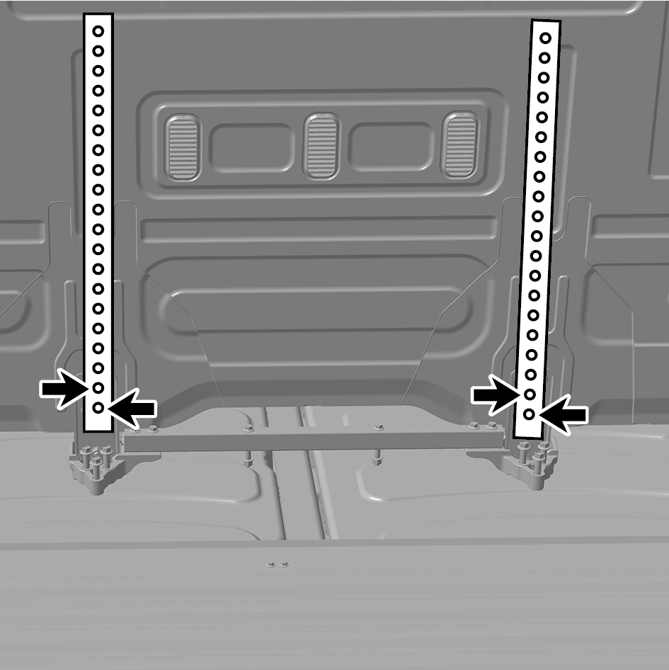
plate and the lifting tool, and install the lifting bracket at
the rear part of the white body assembly.
warning!
It is necessary to use the lifting tools provided or
permitted by Windrose.
The lifting tool should maintain a distance of 5 to 10
centimeters from the rear enclosure of the vehicle
body.
93
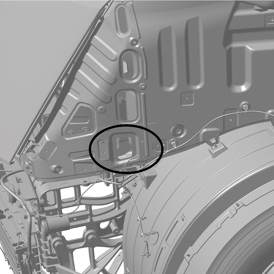
Install the lifting tool at the lifting points of the white body
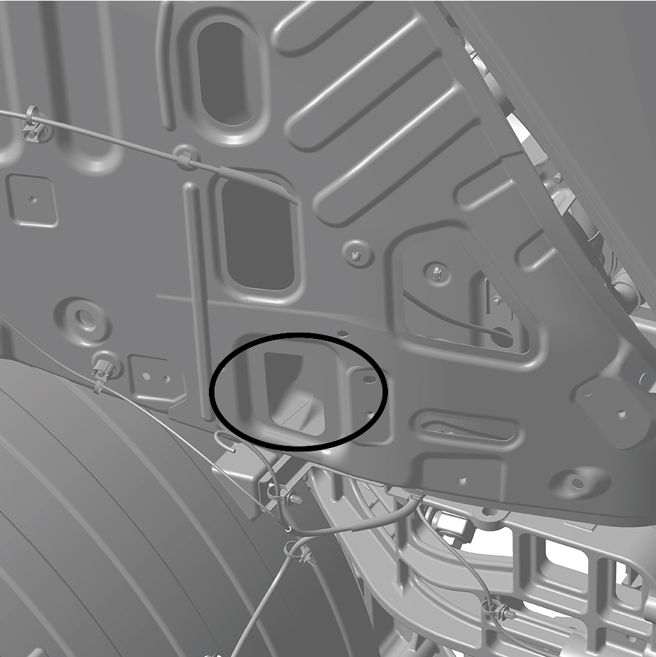
assembly (the lifting points are located at the left and right
lower sides of the front part of the white body assembly).
94
Adjust the lifting tool to the appropriate position to keep
the BIW assembly stable.
95
Lift the BIW assembly.
96
Place the BIW assembly on the storage bracket.
97
Separate the lifting bracket from the BIW assembly.
98
Remove the BIW assembly.
Installation Procedures
1
Move the BIW assembly to the mounting position.
2
Pre-install the cab lifting tool.
3
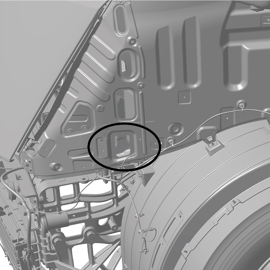
Install the lifting tool at the lifting points of the white body
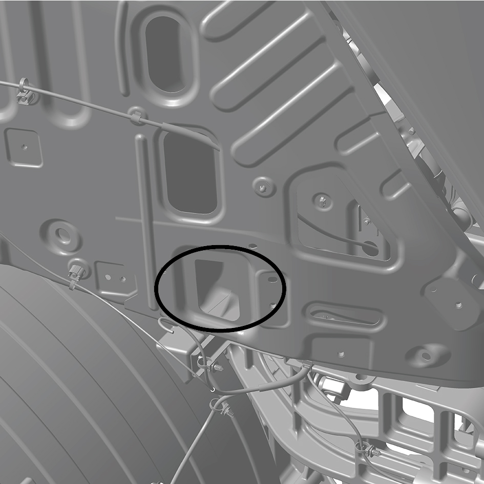
assembly (the lifting points are located at the left and right
lower sides of the front part of the white body assembly).
4
Add a spacer block between the rear enclosure mounting
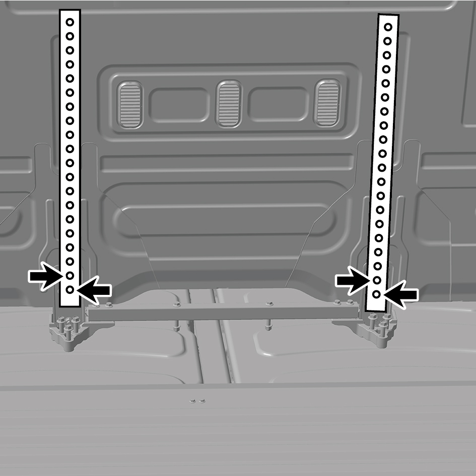
plate and the lifting tool, and install the lifting bracket at
the rear part of the white body assembly.
warning!
It is necessary to use the lifting tools provided or
permitted by Windrose.
The lifting tool should maintain a distance of 5 to 10
centimeters from the rear enclosure of the vehicle
body.
5
Adjust the lifting tool to the appropriate position to keep
the BIW assembly stable.
6
Lift the BIW assembly.
7
Place the BIW assembly on the mounting position.
8
Separate the lifting bracket from the BIW assembly.
9
Install 2 bolt (right upper) of the rear wall mounting plate
(right).
10
Install 2 bolt (left upper) of the rear wall mounting plate
(left).
11
Connect the strap clip of the BIW assembly front wall
harness.
12
Install 2 fixing bolts connecting the BIW assembly to the
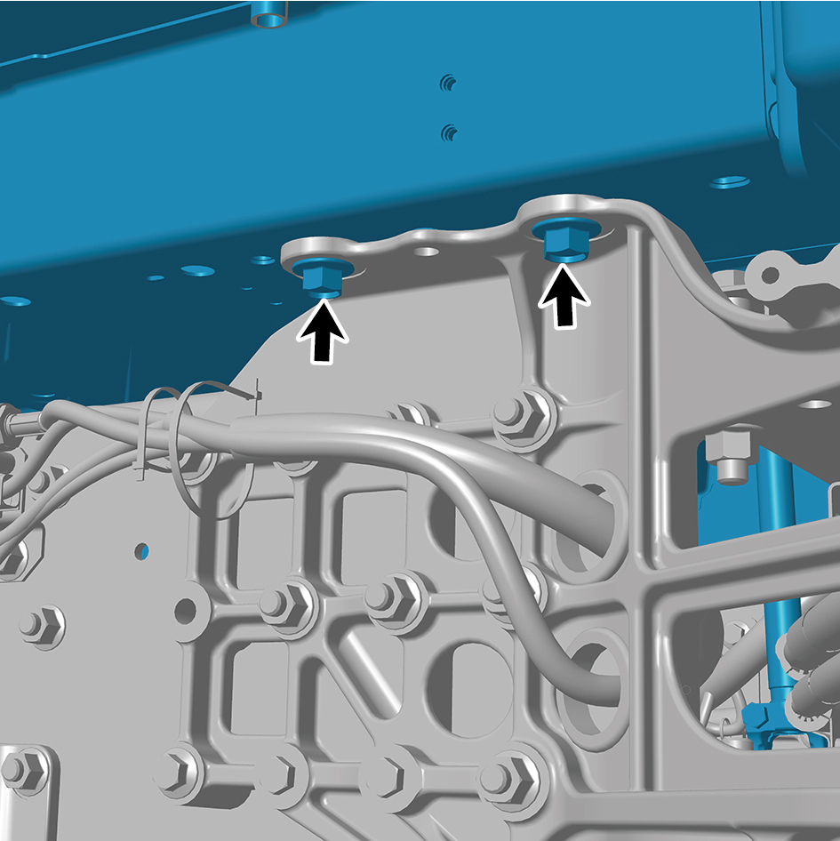
right front joint beam.
Torque: (229 ft-lb +/- 7 ft-lb) ft-lb
13
Install 1 fixing bolt connecting the BIW assembly to the
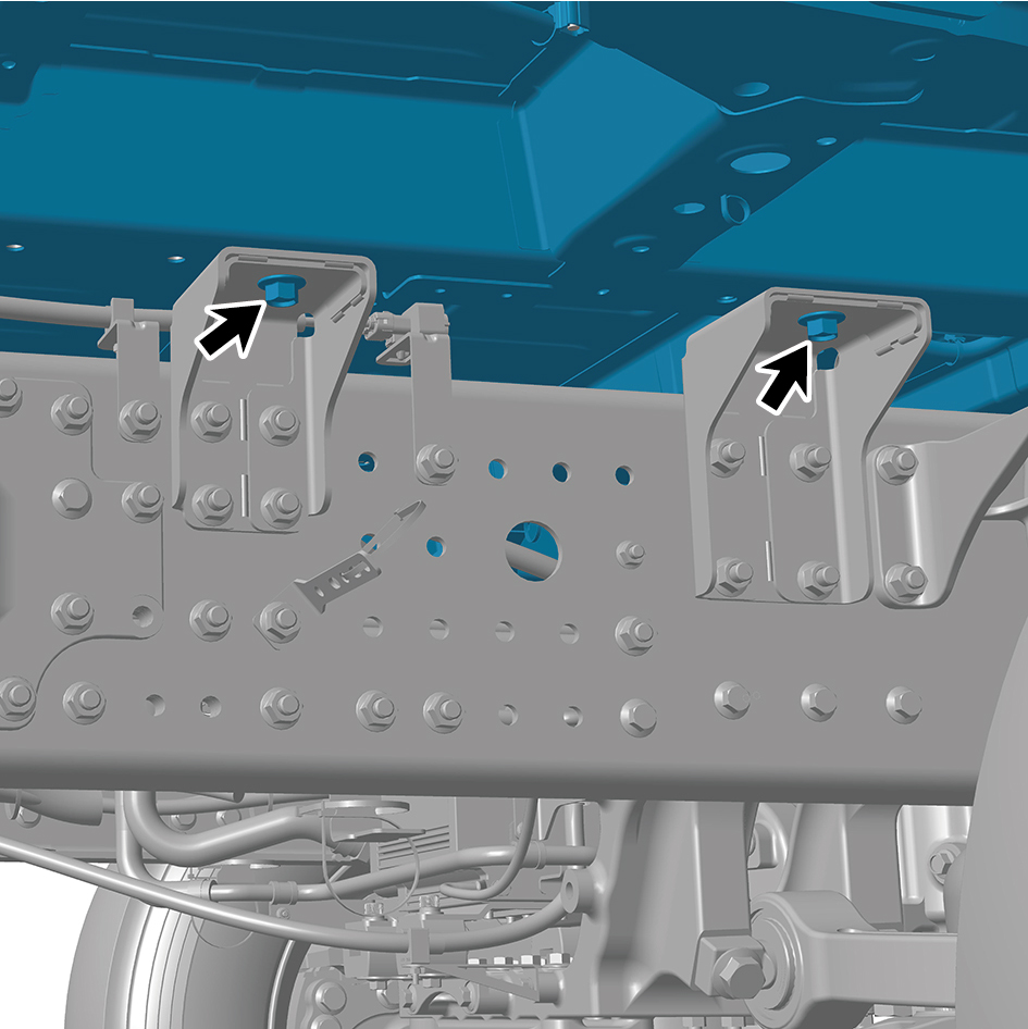
mounting bracket II and III assembly.
Torque: (229 ft-lb +/- 7 ft-lb) ft-lb
14
Install 1 fixing bolt connecting the BIW assembly to the
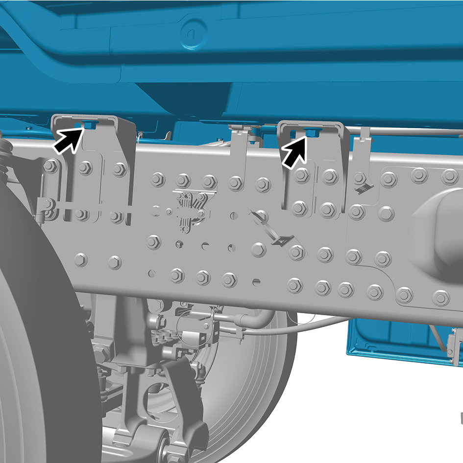
mounting bracket II and III assembly.
Torque: (229 ft-lb +/- 7 ft-lb) ft-lb
15
Install 2 fixing bolts connecting the BIW assembly to the
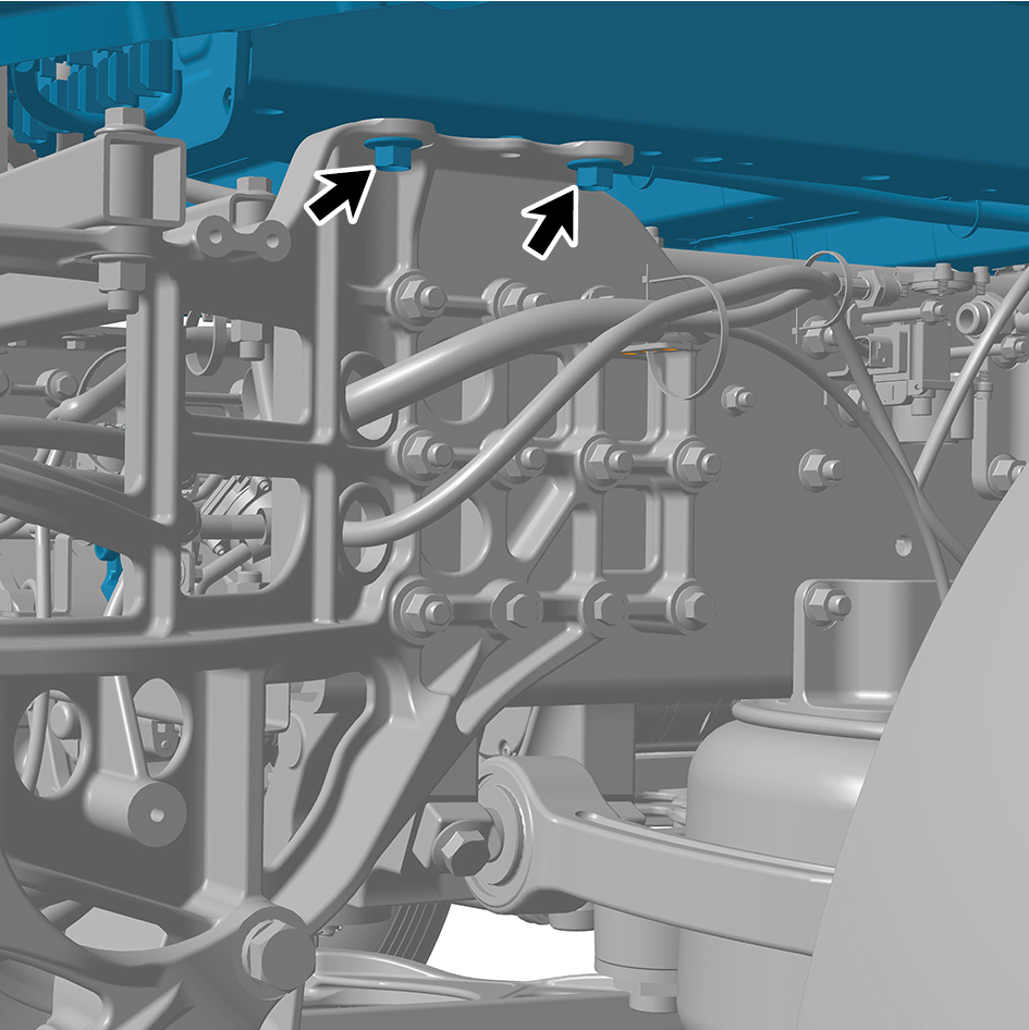
left front joint beam.
Torque: (229 ft-lb +/- 7 ft-lb) ft-lb
16
Install 2 fixing bolts, and connect one A/C pipeline at the
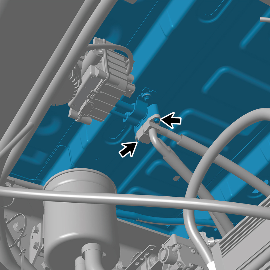
bottom of the BIW assembly.
Torque:(6.5 ft-lb +/- .75 ft-lb) ft-lb
17
Connect 1 high voltage harness connector at the bottom
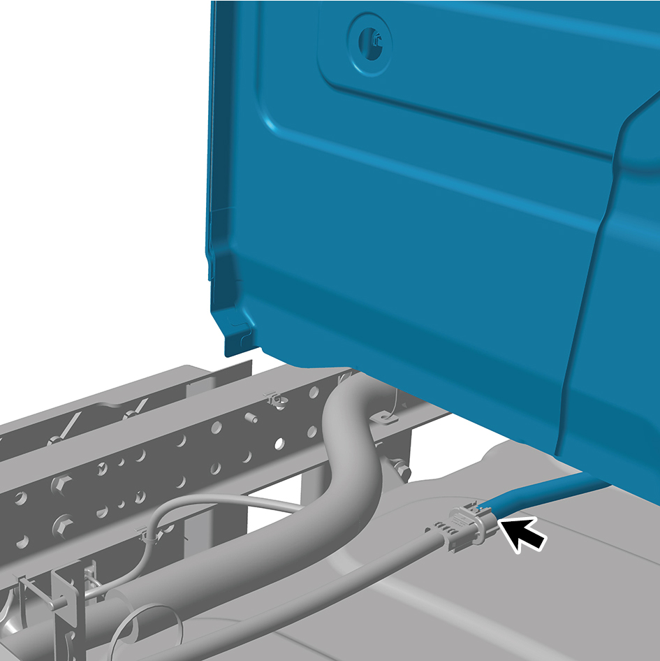
of the BIW assembly.
caution
The harness is firmly connected following the
principal of "insert until a click is heard for
confirmation".
18
Connect 1 high voltage harness connector at the bottom
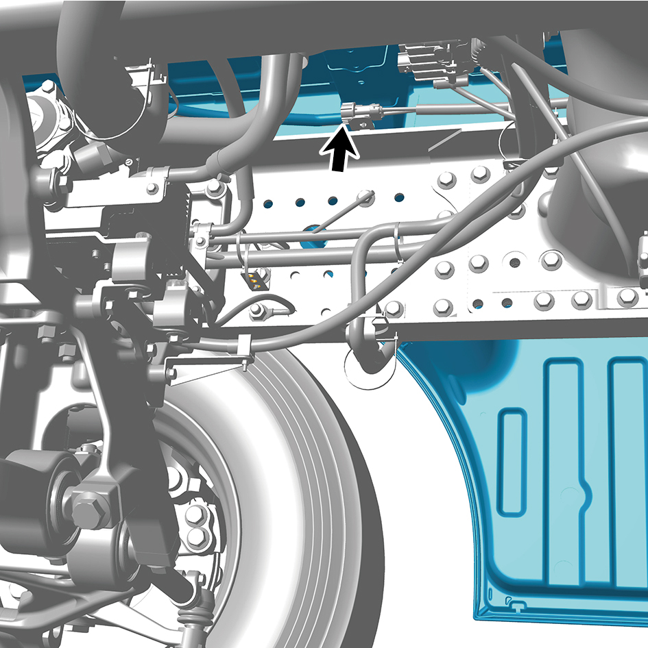
of the BIW assembly.
caution
The harness is firmly connected following the
principal of "insert until a click is heard for
confirmation".
19
Connect 1 high voltage harness connector at the bottom
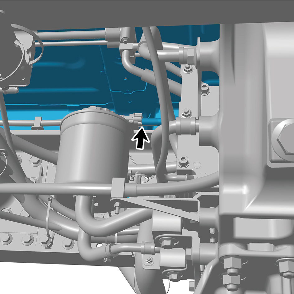
of the BIW assembly.
caution
The harness is firmly connected following the
principal of "insert until a click is heard for
confirmation".
20
Install 1 fixing bolt of the A/C high/low pressure pipe
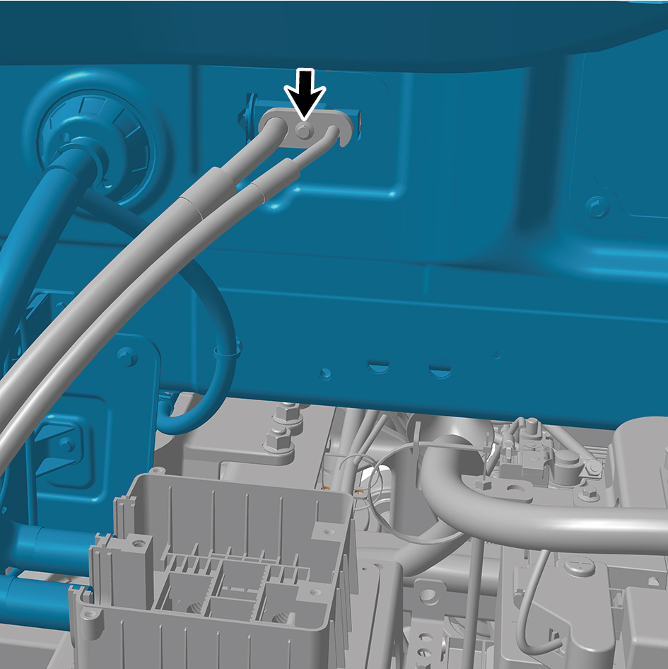
(right), and connect the A/C high/low pressure pipe (right).
Torque:(6.5 ft-lb +/- .75 ft-lb) ft-lb
21
Install 1 fixing bolt of the A/C high/low pressure pipe (left),
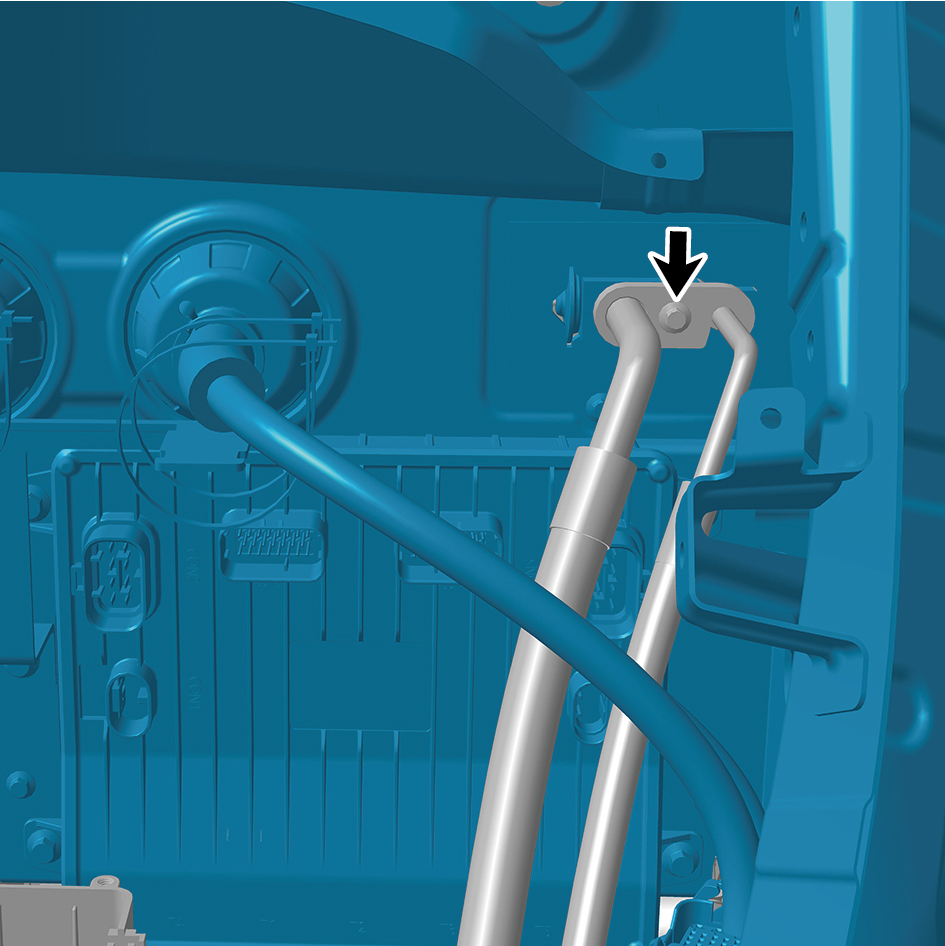
and connect the A/C high/low pressure pipe (left).
Torque: (6.5 ft-lb +/- .75 ft-lb) ft-lb
22
Install 1 fixing bolt of the steering drive shaft, and connect
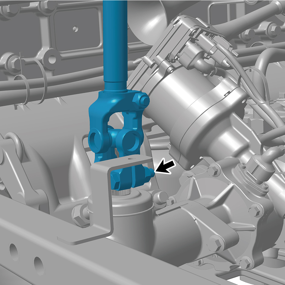
the steering drive shaft to the integrated EHPS assembly.
Torque:(39 ft-lb +/- 5 ft-lb) ft-lb
23
Connect 1 harness connector of the electric horn - high
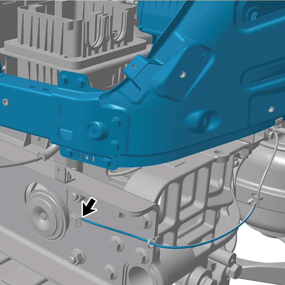
pitch.
caution
The harness is firmly connected following the
principal of "insert until a click is heard for
confirmation".
24
Connect 1 harness connector of the electric horn - low
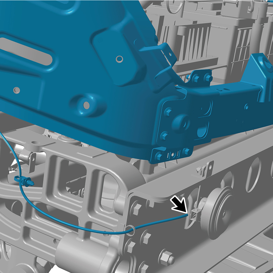
pitch.
caution
The harness is firmly connected following the
principal of "insert until a click is heard for
confirmation".
25
Connect 5 brake air pipes of the brake signal transmitter.
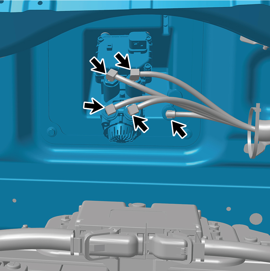
26
Connect 1 harness connector.
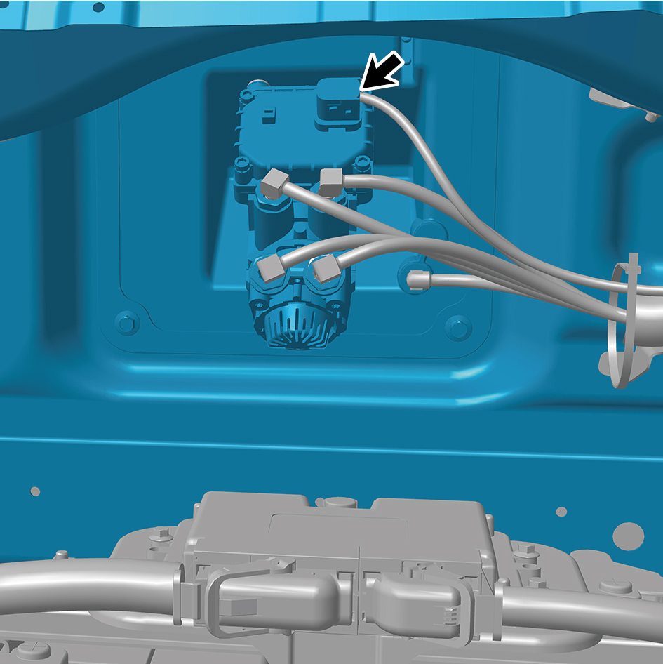
caution
The harness is firmly connected following the
principal of "insert until a click is heard for
confirmation".
27
Install 1 fixing bolt of the BIW assembly ground harness
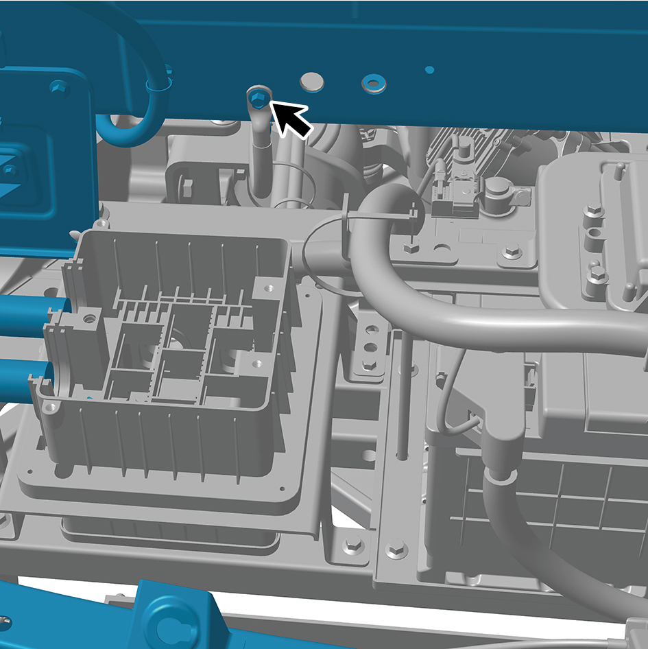
(at Right Junction Box).
Torque:(18.4 ft-lb +/- 2.2ft-lb) ft-lb
28
Install the 4 fixing bolts of the harness.
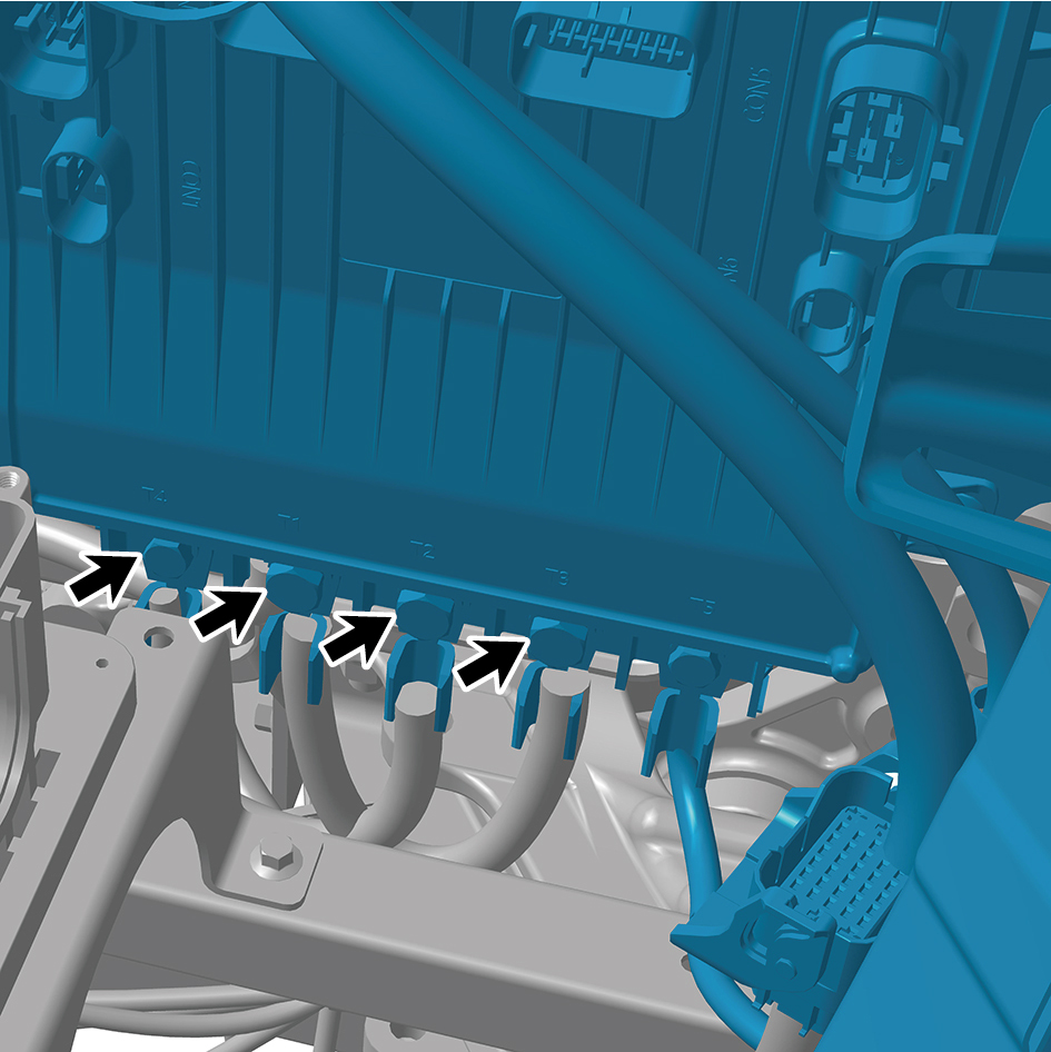
Torque:(18 ft-lb +/- 2 ft-lb) ft-lb
29
Connect 1 harness connector.
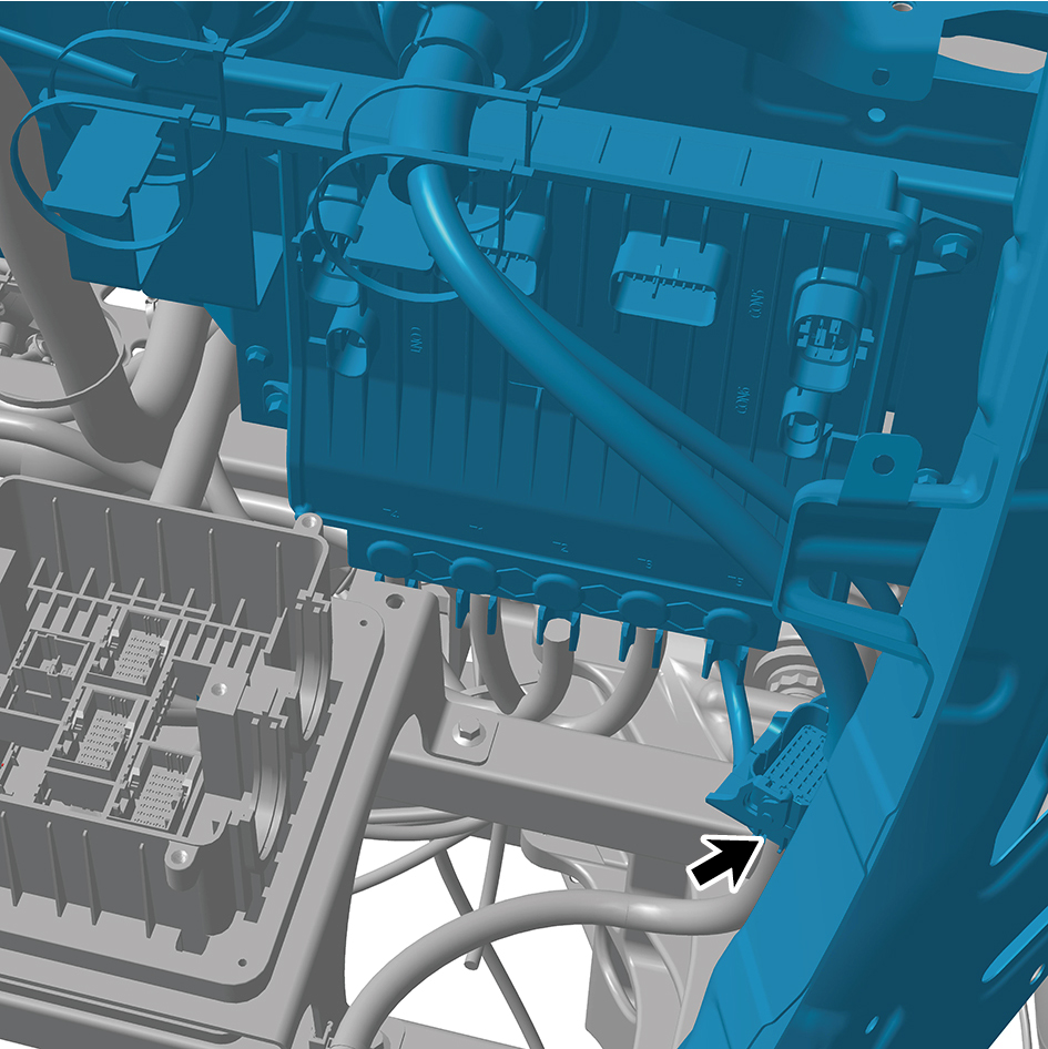
caution
The harness is firmly connected following the
principal of "insert until a click is heard for
confirmation".
30
Install 5 harness clips.
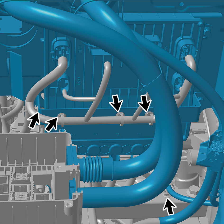
31
Connect 6 harness connector.
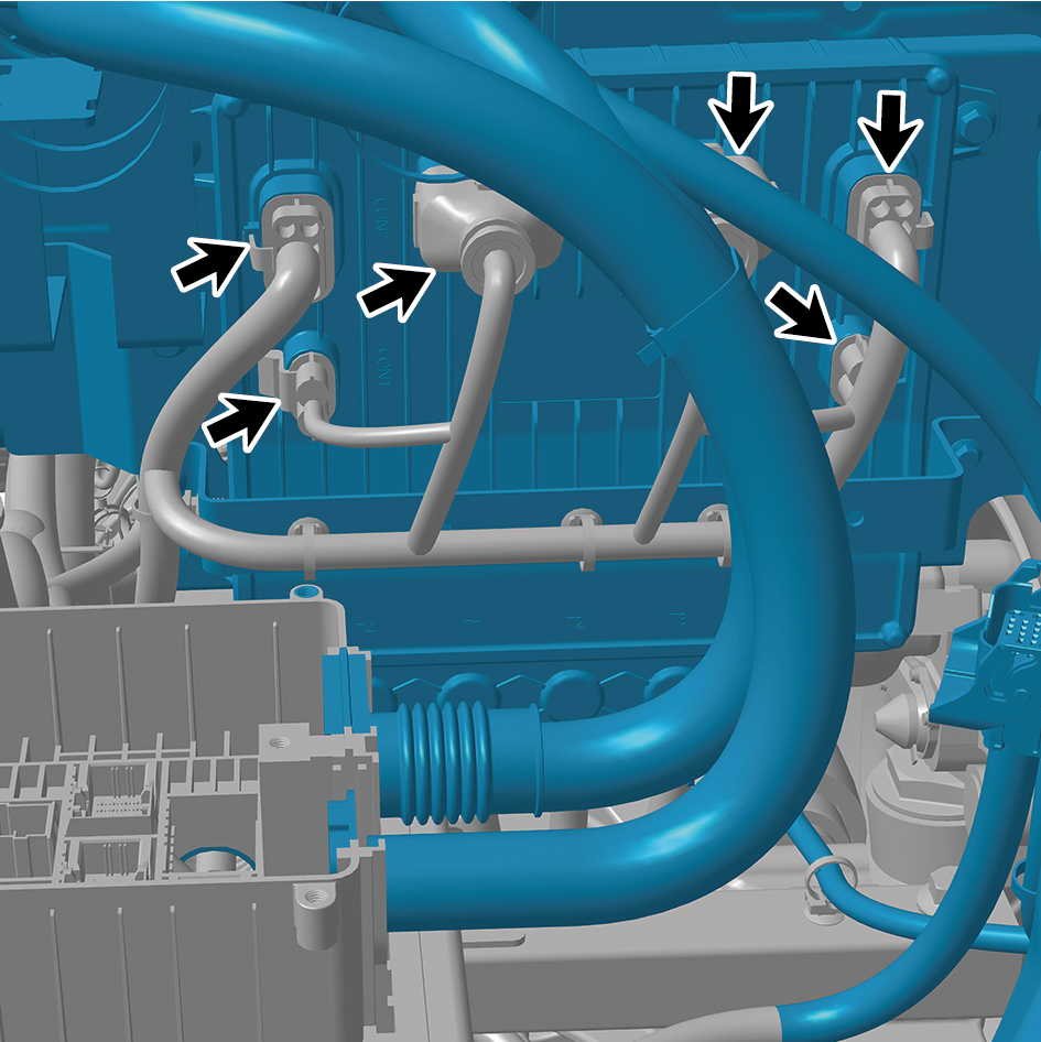
caution
The harness is firmly connected following the
principal of "insert until a click is heard for
confirmation".
32
Install 1 fixing nut of Right Junction Box ground harness,
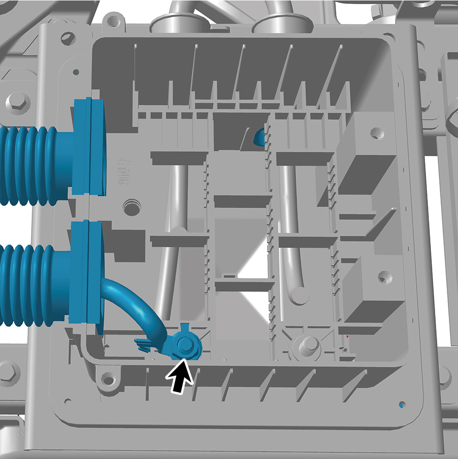
and connect Right Junction Box ground harness.
Torque: (18 ft-lb +/- 2 ft-lb) ft-lb
33
Connect 6 harness connectors of Right Junction Box.
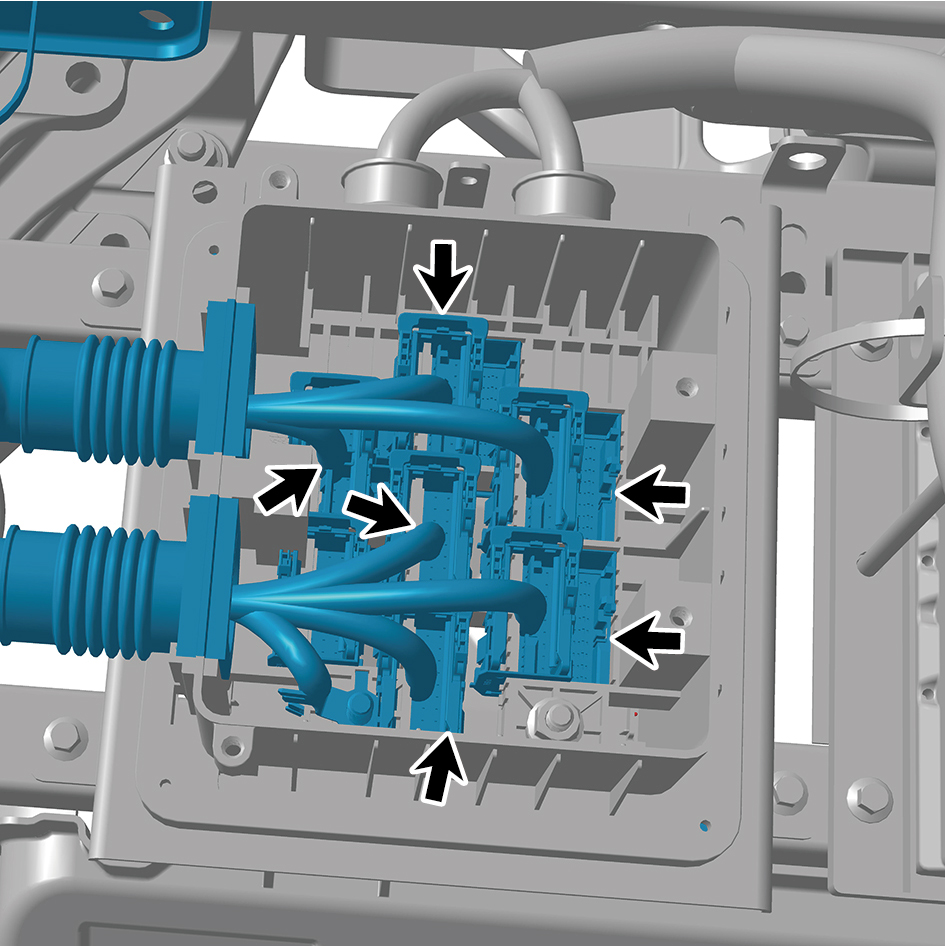
caution
The harness is firmly connected following the
principal of "insert until a click is heard for
confirmation".
34
Install 5 fixing bolts of Right Junction Box cover plate, and
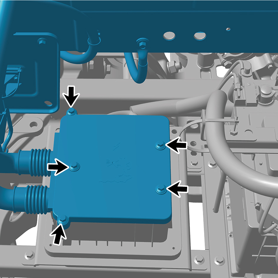
close Right Junction Box.
Torque:(4 ft-lb +/- .75 ft-lb) ft-lb
35
Install 1 fixing nut of Left Junction Box ground harness,
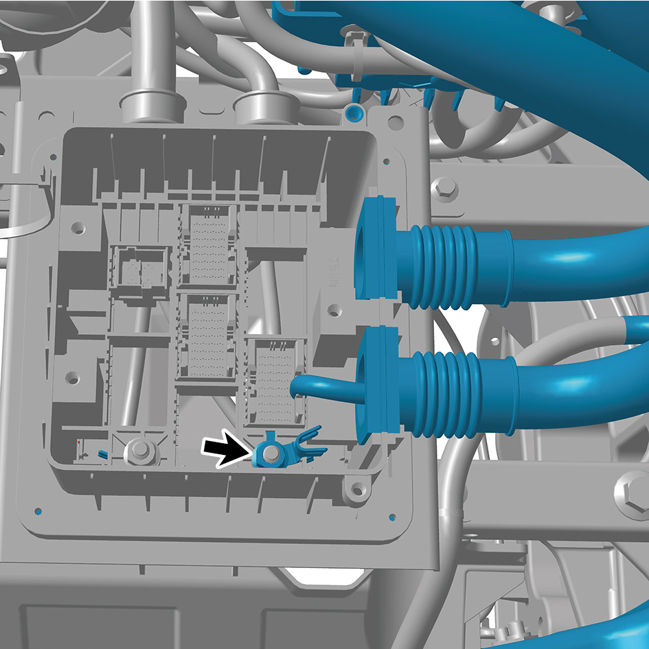
and connect Left Junction Box ground harness.
Torque: (18 ft-lb +/- 2 ft-lb) ft-lb
36
Connect 6 harness connectors of Left Junction Box.
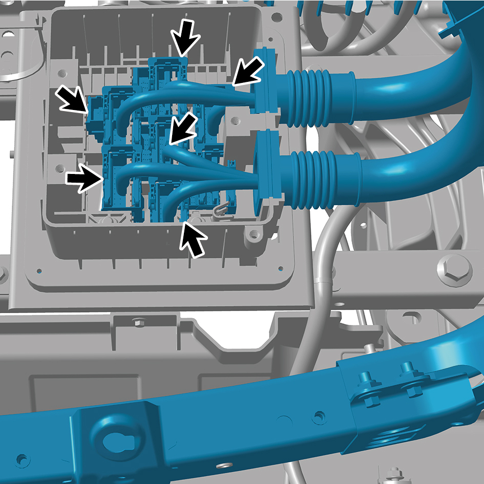
caution
The harness is firmly connected following the
principal of "insert until a click is heard for
confirmation".
37
Install 5 fixing bolts of Left Junction Box cover plate, and
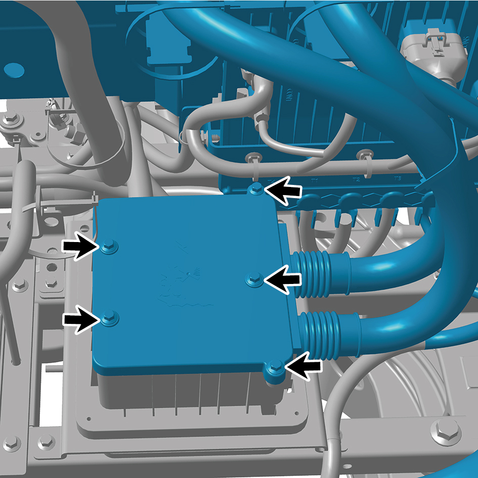
close Left Junction Box.
Torque: (4 ft-lb +/- .75 ft-lb) ft-lb
38
Install the frame main truss.
39
Install the boarding step tubular beam.
40
Install the lower wheel housing connecting bracket.
41
Install the upper wheel housing connecting bracket.
42
Install the boarding step bracket.
43
Install the boarding step body assembly.
44
Install the lamp (lower).
45
Install the lamp (upper).
46
Install the left side wall lower trim panel mounting frame
assembly.
47
Install the left side wall mounting bracket 2.
48
Install the left side wall mounting bracket 1.
49
Install the side wall upper mounting bracket assembly 2.
50
Install the left side wall lower trim panel assembly.
51
Install the right headlamp bracket.
52
Install the right headlamp.
53
Install the right front combination lamp.
54
Install the right fender assembly.
55
Install the right fender trim strip.
56
Install the right triangular cover plate assembly.
57
Install the left headlamp bracket.
58
Install the left headlamp.
59
Install the left front combination lamp.
60
Install the left fender assembly.
61
Install the left fender trim strip.
62
Install the front windshield cover plate assembly.
63
Install the primary wiper arm blade assembly (nozzle and
hose).
64
Install the left physical exterior rearview mirror assembly.
65
Install the front bumper assembly.
66
Install the right cover plate of the corner radar.
67
Install the left cover plate of the corner radar.
68
Install the front MMW radar adapter bracket.
69
Install the forward MMW radar.
70
Install the front MMW radar shield.
71
Install the through-type lamp.
72
Install the engine compartment trim panel body.
73
Install the back integrated bracket upper cover plate.
74
Install the back integrated bracket upper cover plate filler
cap.
75
Install the back integrated bracket middle cover plate
assembly.
76
Install the back integrated bracket side cover plate
assembly (right).
77
Install the back integrated bracket side cover plate
assembly (left).
78
Install the right deflector lower body.
79
Install the right deflector upper body.
80
Install the upper deflector mounting bracket.
81
Install the left deflector lower body.
82
Install the deflector mounting bracket.
83
Install the left deflector upper body.
84
Install the roof deflector middle bracket.
85
Install the roof deflector body.
86
Install the right front wheel housing rear body.
87
Install the left front wheel housing rear body.
88
Install the right front wheel housing body.
89
Install the left front wheel housing body.
90
Fill coolant in the battery thermal management system.
91
Fill coolant in the power system.
92
Lower the front end of the vehicle.
93
Fill with A/C refrigerant.
94
Perform power-on of the high voltage system.
95
Connect the battery negative cable.
96
Close the front flip cover plate.
97
Close the door.
6.4.4.2 Replacement of Sliding Door Assembly
Removal Procedures
1
Open the door.
2
Open the front flip cover plate.
3
Disconnect the battery negative cable.
caution
power down the high-voltage system before
disconnecting the negative pole of the storage
battery.
4
Remove the right side wall lower trim panel assembly.
5
Remove the cable cover plate.
6
Remove the door protective plate assembly.
7
Remove the right body waterproof membrane (Ⅰ).
8
Remove the right body waterproof membrane (II).
9
Remove the towing chain harness assembly.
10
Remove the ground lock assembly.
11
Remove 2 fixing bolts connecting the sliding door
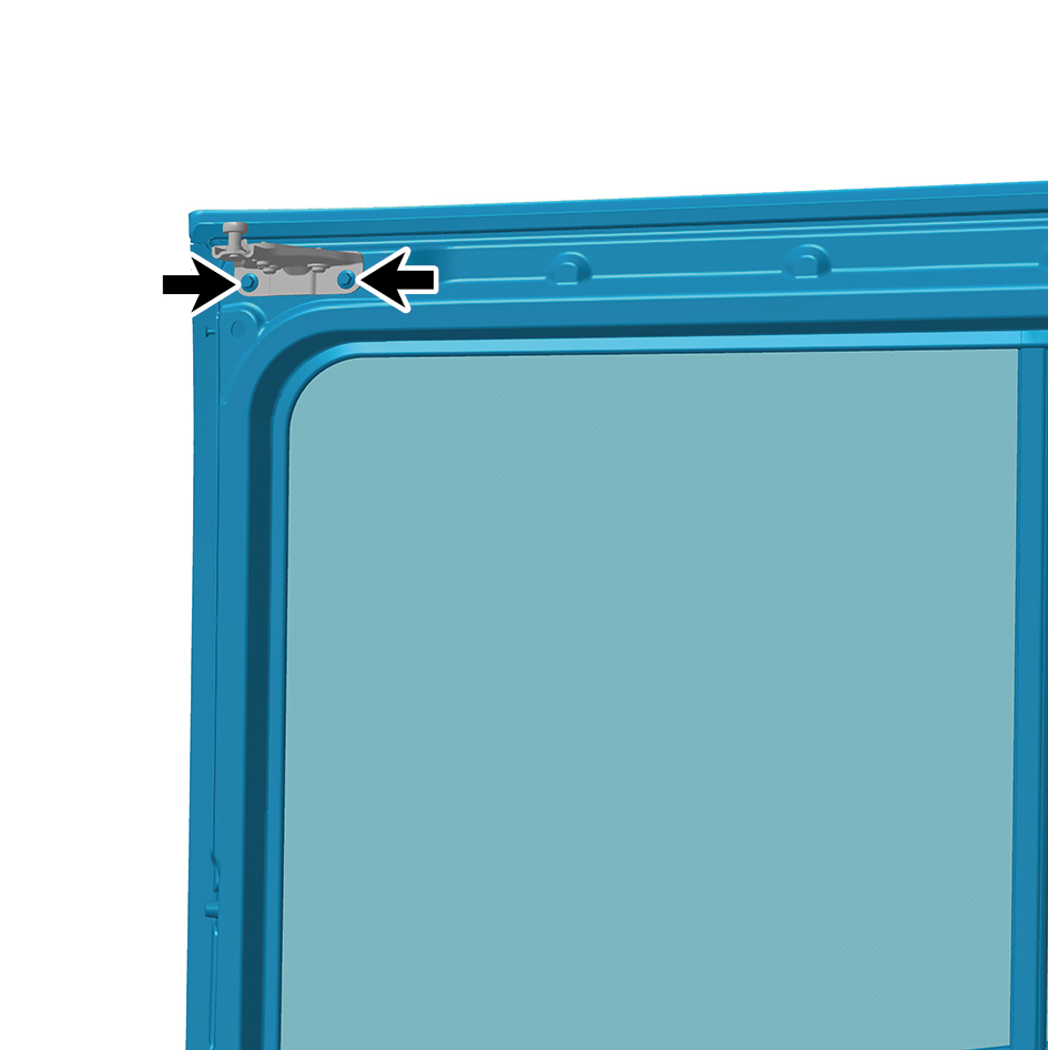
assembly to the upper hinge assembly.
12
Remove 1 fixing nut connecting the sliding door assembly
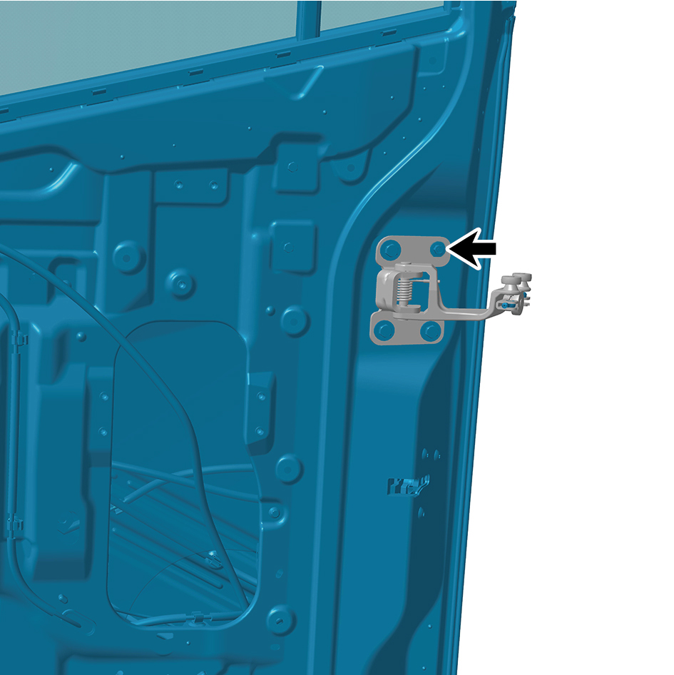
to the middle hinge assembly.
13
Remove 3 fixing bolts connecting the sliding door
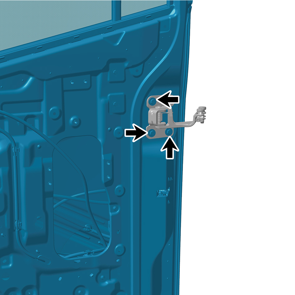
assembly to the middle hinge assembly.
14
Remove 1 fixing nut connecting the sliding door assembly
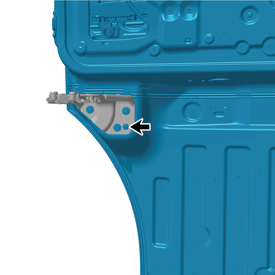
to the lower hinge assembly.
15
Remove 3 fixing bolts connecting the sliding door
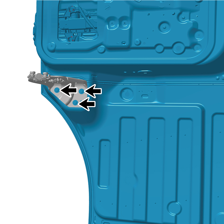
assembly to the lower hinge assembly.
16
Remove the sliding door assembly.
caution
Due to the heavy weight of the sliding door
assembly, it shall be removed with the help of an
assistant.
Installation Procedures
1
Move the sliding door assembly to the mounting position.
caution
Due to the heavy weight of the sliding door
assembly, it shall be moved to the mounting position
with the help of an assistant.
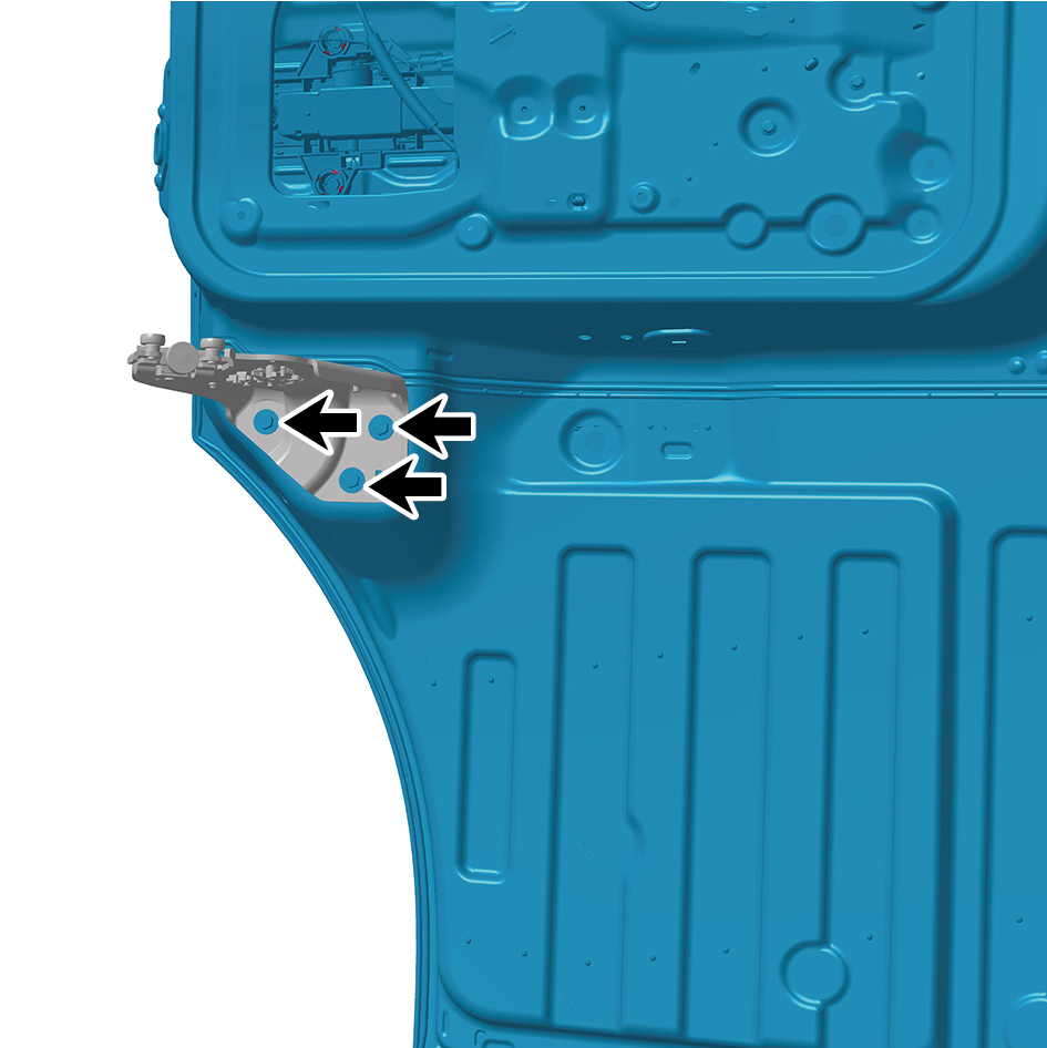
2
Install 3 fixing bolts connecting the sliding door assembly
to the lower hinge assembly.
Torque: (18 ft-lb +/- 2 ft-lb) ft-lb
3
Install 1 fixing nut connecting the sliding door assembly to
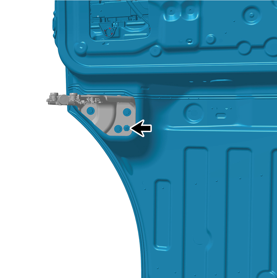
the lower hinge assembly.
Torque: (18 ft-lb +/- 2 ft-lb) ft-lb
4
Install 3 fixing bolts connecting the sliding door assembly
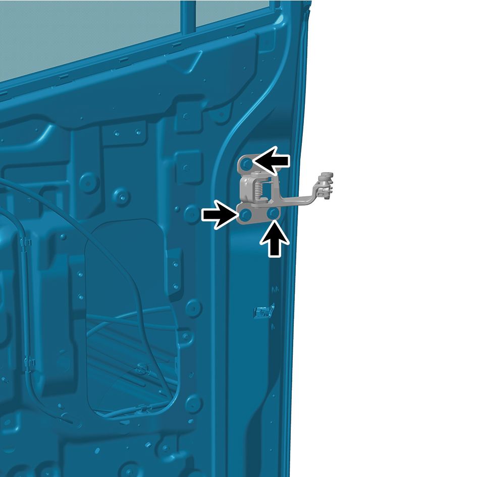
to the middle hinge assembly.
Torque:(18 ft-lb +/- 2 ft-lb) ft-lb
5
Install 1 fixing nut connecting the sliding door assembly to
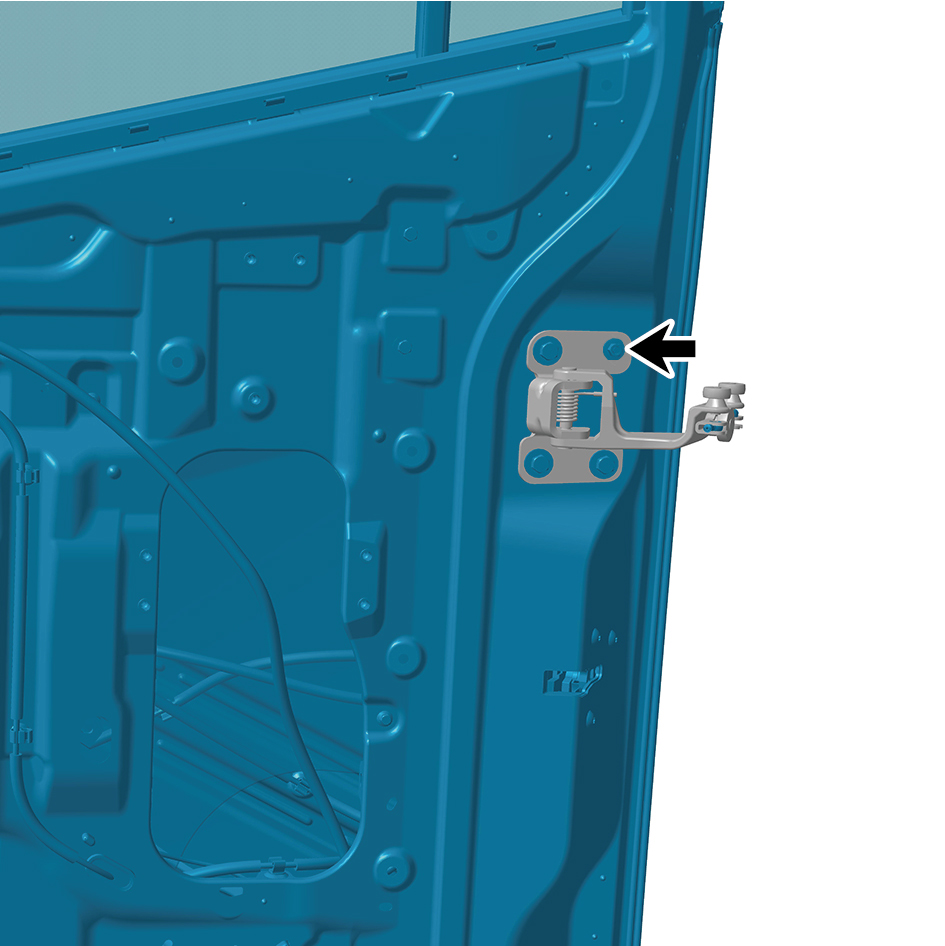
the middle hinge assembly.
Torque:(18 ft-lb +/- 2 ft-lb) ft-lb
6
Install 2 fixing bolts connecting the sliding door assembly
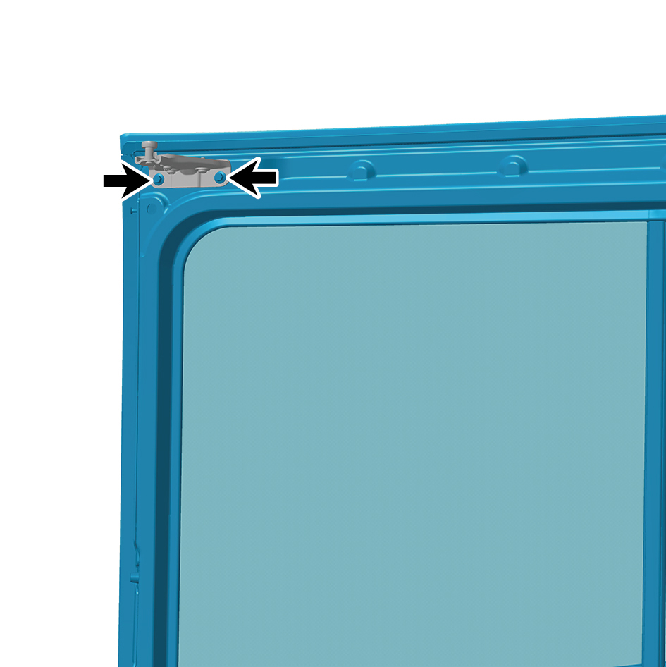
to the upper hinge assembly.
Torque:(18 ft-lb +/- 2 ft-lb) ft-lb
7
Install the ground lock assembly.
8
Install the towing chain harness assembly.
9
Install the right body waterproof membrane (II).
10
Install the right body waterproof membrane (Ⅰ).
11
Install the door protective plate assembly.
12
Install the cable cover plate.
13
Attach the right side wall lower trim panel assembly.
14
Connect the battery negative cable.
15
Close the front flip cover plate.
16
Close the door.