← Back to Contents
5 Intelligent Driving / 5.1 Intelligent Driving Device | PDF pages 371-437
5.1 Intelligent Driving Device
5.1 Intelligent Driving Device
5.1.1 Specifications
5.1.1.1 Fastener Specifications
Range Of Torque
Fastener Specifications
Specifications
Metric System(ft-lb)
The fixing bolt connecting the front
M6
7 ft-lb +/- .75 ft-lb
millimeter wave radar adapter bracket to
the millimeter wave radar bracket
The fixing bolt connecting the millimeter
wave radar bracket to the front lower
M8
17 ft-lb +/- 1.5 ft-lb
protection assembly
The fixing bolt connecting the forward
millimeter wave radar and the forward
M5
4 ft-lb +/- .75 ft-lb
millimeter wave radar adapter bracket
Rubber cushion assembly connecting
side millimeter wave radar c o v e r and
M8
9 ft-lb +/- .75 ft-lb
side skirt
Fixing screw connecting the
M2.9
2.21 +/-5.90 ft-lb
forward‑facing intelligent camera to the
front windshield bracket
Forward facing MOIS camera and front
M3.5
3 ± 0.5
bumper bracket
Side blind camera and electronic
M4.2
3 ± 0.5
rearview mirror base
BSIS alarm and A-pillar guard base
M3.5
3 ± 0.5
BSIS controller and ADAS controller
M5
9 ± 1
bracket
ISA controller and ADAS controller
M5
9 ± 1
bracket
9 ± 1
ADAS controller bracket and white body
M6
9 ± 1
GPS antenna bracket and ceiling
M6
Rear view camera and bracke
M4
2 ± 0.5
5.1.2 Decomposition Diagram
5.1.2.1 Decomposition Diagram
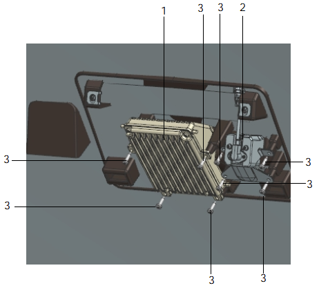
1.
3.
Self-Tapping Scre
Front View Intelligent Camera
2.
ISTA Camera
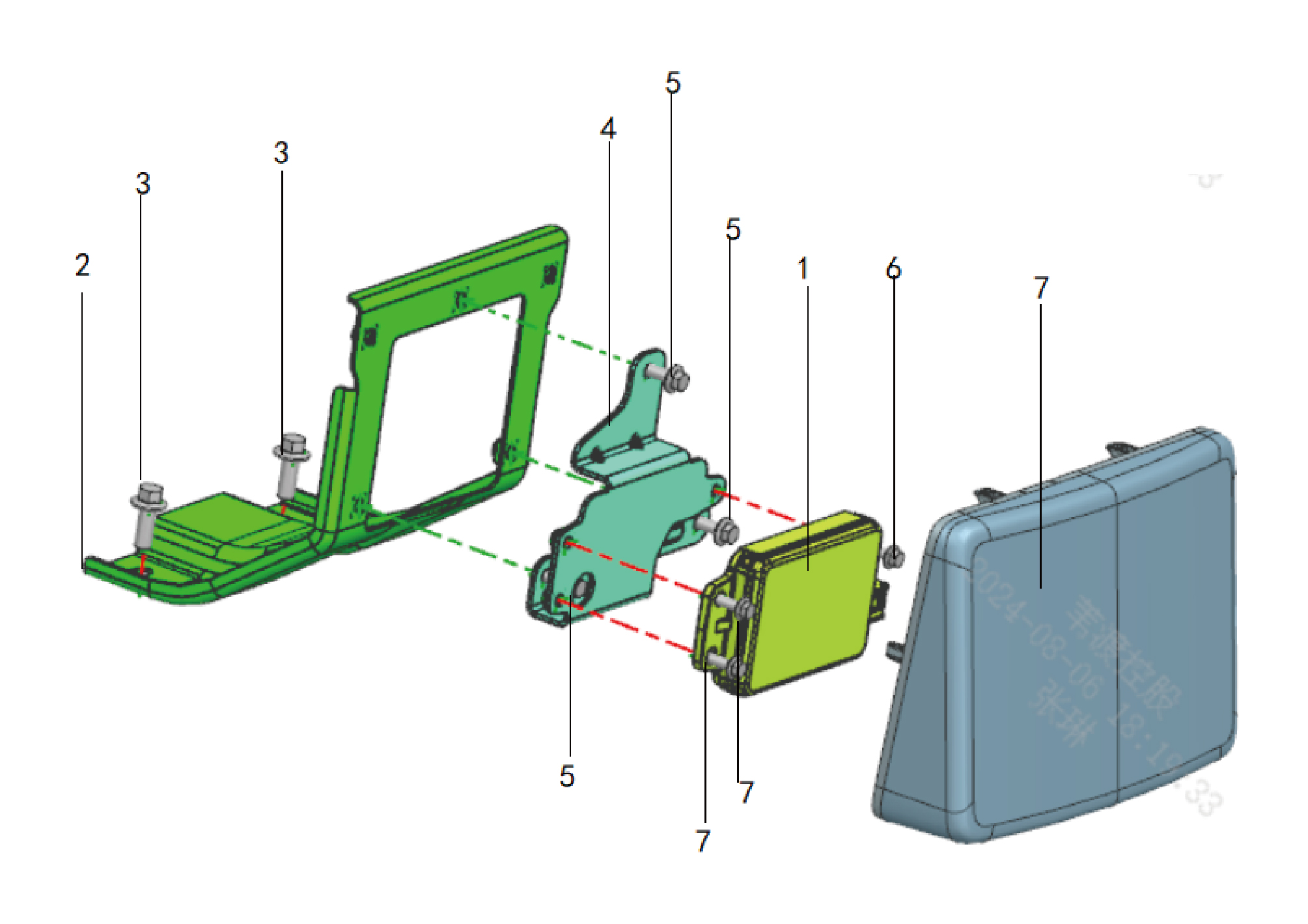
5.
1.
Front Millimeter-Wave Radar
Hexagon Flange Bolt
2.
6.
Hexagon Flange Bolt
Bracket for Front Millimeter Wave Radar
7.
3.
Hexagon Flange Bolt
Cover-Front Millimeter Wave Radar
4.
Adapter Brkt-Front Millimeter Wave Radar
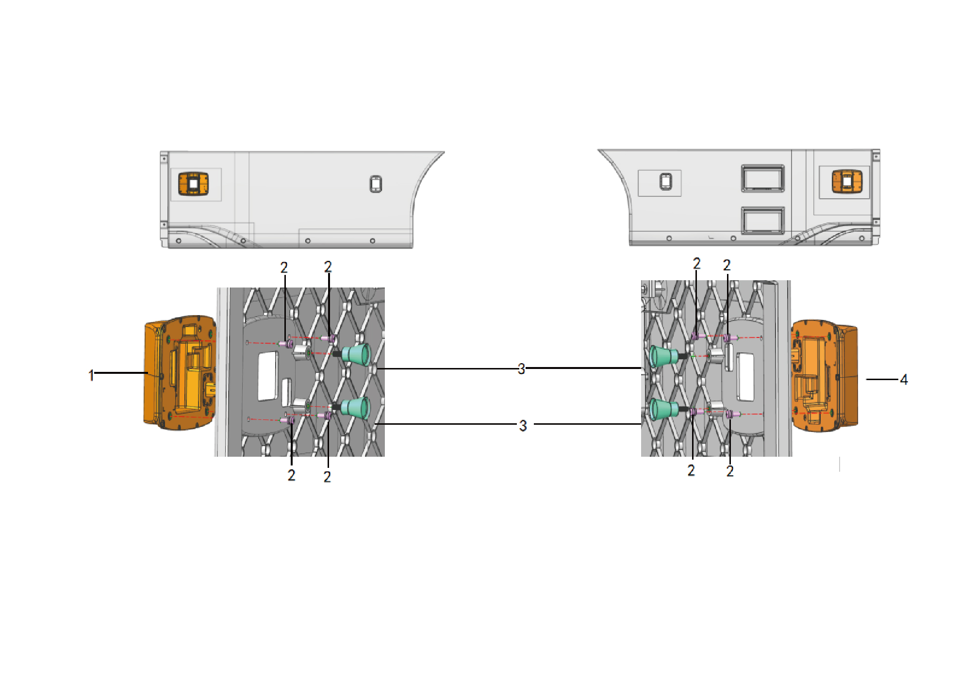
1.
3.
Rubber Buffer
S i d e r a d a r s h i e l d s
2.
4.
S i d e r a d a r s h i e l d s
Cross Recessed Pan Head Screw Assy
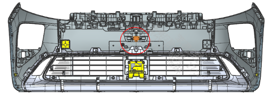
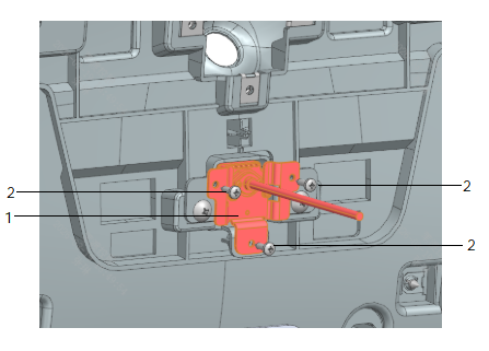
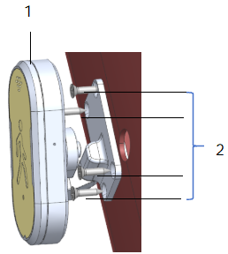
1.
MOIS camera
1.
BSIS camera
2.
2.
Self-Tapping Screw
Self-Tapping Screw
5.1.3 System Schematic Diagram
5.1.3.1 Electrical Schematic Diagram
5.1.4 Diagnostic Information and Steps
5.1.4.1 Diagnosis Description
Understanding and familiarizing oneself with the working principle of intelligent driving devices before diagnosing their faults, and
then starting system diagnosis, can help determine the correct fault diagnosis steps when a fault occurs, and more importantly, it
can help determine the situation described by the customer belongs to normal operation. Any fault diagnosis of intelligent driving
devices should start with routine inspection, guiding maintenance personnel to take the next logical step for fault diagnosis.
Understanding and correctly using the diagnostic process can shorten the diagnosis time and avoid misjudgment of faulty parts.
5.1.4.2 Routine Inspection
• Check for aftermarket devices that may affect the operation of the intelligent driving device system, ensuring that these devices
do not affect the operation of the intelligent driving device system.
• Inspect system components that are easily accessible or visible to make sure they are not visibly damaged or have conditions
that could cause failure.
5.1.4.3 Fault Symptom Table
Symptom
Suspected malfunctiony project
Measures
1. The panoramic camera is obstructed
Clean or replace the panoramic camera.
or damaged
Check the wiring harness between the
After turning on the panoramic image,
2. Panoramic camera wiring harness
panoramic camera and CDC.
the CAR screen does not display the
malfunction
image
3. LVDS signal harness fault between
Check the LVDS signal harness
CAR screen and CDC
between the CAR screen and CDC.
Refer to Replacement Of CAR screen
4. CAR screen
5.1.4.4 DTC Confirmation
1.Connect the diagnostic instrument to the diagnostic interface, read and record the DTC, and then clear the DTC.
2. Restart the vehicle.
3. Read the malfunction code of the control system again to confirm whether the system has a malfunction code output.
– Yes:Diagnose based on the output malfunction code.
– No:Perform intermittent malfunction checks, refer to Inspection Of Intermittent Faults
5.1.4.5 List Of Diagnostic Trouble Codes (DTCs)
CAMF
Fault Description
Exclusion Method
Fault Code
High battery voltage
B111717
Refer to Front View Intelligent Camera
Power Fault
Low battery voltage
B111716
U019887
Lost Communication With TGW
U014087
Lost Communication With BDCU
U019987
Lost Communication With DCM
U015687
Lost Communication With CDCU
U012287
Lost Communication With VDC
U012187
Lost Communication With EBS
U013087
Lost Communication With EPS
Refer to Front View Intelligent Camera
U013287
Lost Communication With ECAS
Communication Fault
U012887
Lost Communication With EPB
U007888
CANFD6 BusOff
U122000
Invalid data received from CDCU
U122100
Invalid data received from EPS
C180008
VDC Performance Abnormal
C180108
EBS Performance Abnormal
U122208
EPS Performance Abnormal
U122344
ADCU Internal failure
Refer to Internal Fault Of Front View
Front View Intelligent Camera State
U122C00
Intelligent Camera
Error
U122D00
Front Radar State Error
Brake Switch Signal Error
C180202
Refer to Brake Pedal Switch Fault
Vehicle Speed Signal Error
C180302
Left-Front Wheel Speed Signal Error
C180702
Refer to Vehicle Speed Signal Fault
Right-Front Wheel Speed Signal Error
C180802
Left-Rear Wheel Speed Signal Error
C180902
Right-Rear Wheel Speed Signal Error
C180A02
Yaw Rate Signal Error
C180402
Lateral Acceleration Signal Error
C180502
Longitudinal Acceleration Signal Error
C180602
Master Cylinder Pressure Signal Error
C180B02
Road Grade Signal Error
C180C02
Absoluted Steering Angle Signal Error
U122402
Refer to Front View Intelligent Camera
Reports Other System Fault
Steering Speed Signal Error
U122502
Steering Torque Signal Error
C180D02
Motor Torque Signal Error
U122602
Motor Speed Signal Error
U122702
Gear State Signal Error
U122A02
Meter Vehicle Speed Signal Error
C180F02
BSIS_L
Fault Descr
iption
Exclusion Method
Fault
Code
Wiring check, Replace wiring harness
Lost Communication With TGW
U019887
Wiring check, Replace wiring harness
Lost Communication With BDCU
U014087
Wiring check, Replace wiring harness
Lost Communication With CDCUt
U015687
Wiring check, Replace wiring
harness
U012287
Lost Communication With VDC
Wiring check, Replace wiring harness
U012187
Lost Communication With EBS
Check power supply
Power supply voltage below threshold
B111716
Check power supply
Battery Voltage too High
B111717
ESSB_L-CAN_bus_busoff_faults
Check CAN wiring harness
U007488
Check ESSB_L
C2102FF
ESSB_L_system_kernel_service_stop
Check the network connection.
OEL signal lost
U1462FF
Check Left_BCM
Check the network connection.
ETC2 sigal lost
U1463FF
Check Left_BCM
_R
BSIS
Fault Description
Exclusion Method
Fault
Code
Lost Communication With TGW
Wiring check, Replace wiring harness
U019887
Wiring check, Replace wiring
harness
Lost Communication With BDCU
U014087
Wiring check, Replace wiring harness
Lost Communication With CDCU
U015687
Wiring check, Replace wiring harness
U012287
Lost Communication With VDC
Wiring check, Replace wiring harness
U012187
Lost Communication With EBS
Check power supply
Power supply voltage below threshold
B111716
Check power supply
Battery Voltage too High
B111717
Check CAN wiring harness
ESSB_R-CAN_bus_busoff_fau
U007488
Check ESSB_R working status
C2202FF
ESSB_R_system_kernel_service_stop
Check the network connection.
OEL signal lost
U1472FF
Check Left_BCM
ICheck the network connection.
ETC2 signal lost
U1473FF
Check Left_BCM
ISA
Fault Description
Exclusion Method
Fault
Code
Lost Communication With TGW
Wiring check, Replace wiring harness
U019887
Wiring check, Replace wiring harness
Lost Communication With BDCU
U014087
Wiring check, Replace wiring harness
U015687
Lost Communication With CDCU
Fault Description
Exclusion Method
Fault Code
Lost Communication With VDC
Wiring check, Replace wiring harness
U012287
Lost Communication With EBS
Wiring check, Replace wiring harness
U012187
Power supply voltage below threshold
Check power supply
B111716
Battery Voltage too High
Check power
supply
B111717
Check CAN wiring harness
ESSA-CAN_bus_busoff_faults
U007488
Check ESSA wiring harness
ESSA_system_kernel_service_stop
C2002FF
Check power supply
ESSA_can't_get_image_ISAcamera
C2003FF
Check wiring harness
ESSA_can't_get_image_DDAWcamera
C2004FF
GPS_module_antenna_short_circuit
Power on/off again
C2006FF
Check the network connection.
signal lost
OEL
U1452FF
Check FDM
EBC2 signal lost
U1454FF
Check the network connection.
ESSA Signal Faults
U1455FF
System setting
ESSA signal lost
Check wiring harness
U1456FF
Check the network connection.
TCO1 signal lost
U1457FF
Check
FDM
Check the network connection.
CCVS1 signal lost
U1458FF
Check FDM
Check the network connection.
EBC1 signal lost
U1459FF
Check FDM
Check the network connection.
EEC2 signal lost
U145AFF
Check FDM
ISA_camera_image_video_masking
Check wiring harness
C2007FF
Check wiring harness
C2008FF
DDAW_camera_image_video_masking
Fault Description
Exclusion Method
Fault Code
5.1.4.6 Front View Intelligent Camera Power Fault
1.DTC Monitoring Logic
Description
DTC Trigger Conditions
Faulty Part
DTC Code
High battery voltage
Voltage > 32 V, t > 5000ms
1. Main battery
B111717
2. Low voltage
charging system
3. Wiring harness
Low battery voltage
Voltage < 18V, t > 30s
B111716
4. Front view
intelligent camera
2.Circuit Diagram
Smart Junction Box - Chassis
Battery
Front camera
KL15-1 G01a
KL15 G01
C1-1
KL15 Power
supply 1 G01
38
1
I_B_RR
I7_C_B
38
1
I_RR_B
I7_B_C
KL15+ G01
KL15-1 G01a
KL15+ G01i
RR12-5
C90-5
Front millimeter wave radar
Front View Intelligent Camera
RR12-9
RR12-3
RR12-10
RR12-12
RR12-8
C90-1
C90-3
C90-4
HMI private CAN-H AH01
HMI private CAN-H AH01
HMI private CAN-L AL01
HMI private CAN-L AL01
Intelligent driving
Intelligent driving
CAN-H TH06d
Ground - Z55
CAN-L TL06d
Ground Z38
2
3
26
27
I8_C_B
I8_C_B
I_B_RR
I_B_RR
35
34
I_RR_B
I_RR_B
2
3
26
27
I8_B_C
I8_B_C
I_RR_B
I_RR_B
35
34
I_B_RR
I_B_RR
HMI private CAN-H AH01
HMI private CAN-L AL01
Intelligent driving CAN-H TH06
Intelligent driving CAN-L TL06
G13
G09
B76-7
B76-21
T-gateway A
3. Diagnostic Steps
Step 1:DTC Confirmation. Refer to DTC Confirmation
Step 2:Routine Inspection. Refer to Routine Inspection
Step 3:Check if there are any other module power failure codes besides the Front view intelligent camera?
Check the main battery. Refer to Inspection Of The Main Battery
– Yes:
Check the low-voltage charging system. Refer to DCDC1 Low-voltage Charging System Fault
Next step
– No:
Step 4:Check the power and grounding harness of the front view intelligent camera.
Step 5:Rewrite the configuration code, reload the software, and upgrade the front view intelligent camera.
Step 6:Replace the front view intelligent camera. Refer to Replacement Of Forward Looking Intelligent Camera
Step 7:Clear and confirm DTC.
5.1.4.7 Front View Intelligent Camera Communication Fault
1.DTC Monitoring Logic
Description
DTC Trigger Conditions
Faulty Part
DTC Code
(1) 10 seconds after power on initialization
(2)CAN not in busoff state
Lost Communication
U019887
(3)Any of the following monitoring messages is
With TGW
missing , t > 5000ms ID :0x18FEE6EE
(1) 10 seconds after power on initialization
(2)CAN not in busoff state
Lost Communication
U014087
(3)Any of the following monitoring messages is
With BDCU
missing , t > 1000ms
ID:0xCFDCC21.0x14FD1721.0x18FF6121
(1) 10 seconds after power on initialization
(2)CAN not in busoff state (
Lost Communication
U019987
1.Wiring harness
(3)Any of the following monitoring messages is
With DCM
2.Front view
missing , t > 1000ms ID:0x18FDA54F
intelligent camera
(1) 10 seconds after power on initialization
(2)CAN not in busoff state
(3)Any of the following monitoring messages is
Lost Communication
U015687
With CDCU
missing , t > 1000ms
ID:0x18FF0C41.0x18FF6341.0x18FF1B41.0x18FEA-
E41.0x18FEC1EE.0x18FF6017
(1) 10 seconds after power on initialization
(2)CAN not in busoff state
(3)Any of the following monitoring messages is
Lost Communication
U012287
missing , t > 1000ms
With VDC
ID:0x18F01127.0xCF00400.0x18F06A27.0x18FE-
F100.0x18F00F27.0x18011727
Description
DTC Trigger Conditions
Faulty Part
DTC Code
(1) 10 seconds after power on initialization
(2)CAN not in busoff state
(3)Any of the following monitoring messages is
Lost Communication
U012187
missing , t > 1000ms
With EBS
ID:0x18F0010B.0x18FDC40B.0x18F0090B.0x8FE6E0-
B.0x18FEAD0B
(1) 10 seconds after power on initialization
(2)CAN not in busoff state
Lost Communication
U013087
(3)Any of the following monitoring messages is
With EPS
missing , t > 1000ms ID:0x18FF0513.0x18FF0613
(1) 10 seconds after power on initialization
(2)CAN not in busoff state
Lost Communication
U013287
(3)Any of the following monitoring messages is
With ECAS
missing , t > 1000ms ID:0x18FE582F
(1) 10 seconds after power on initialization
(2)CAN not in busoff state
Lost Communication
U012887
(3)Any of the following monitoring messages is
With EPB
missing , t > 1000ms ID:0x18FE1250.0xCF01350
(1) 10 seconds after power on initialization
U007888
CANFD6 BusOff
(2)The Bus Off counter is equal to 8
(1) 10 seconds after power on initialization
(2)CAN not in busoff state
(3)Monitoring message 0x18FF6341 CDCUStatus
Invalid data received
U122000
reporting status error
from CDCU
(4)The rolling counter or check sum in any of the
following monitoring message is invalid, t > 2000ms
ID:0x18FF0C41.0x18FF1B41.0x18FF6341
(1) 10 seconds after power on initialization
(2)CAN not in busoff state
Invalid data received
U122100
(3)The rolling counter or check sum in any of the
from EPS
following monitoring message is invalid, t > 500ms
ID:0x18FF0513.0x18FF0613
Detected low control performance valid
(1)ADAS system torque control command error
percentage is too large and has accumulated for more
VDC Performance
than a certain period of time
C180008
Abnormal
Returned Operational State Error valid
(1) 10 seconds after power on initialization
(2) ID 0x18F06A27 VDC Status reporting error status
Description
DTC Trigger Conditions
Faulty Part
DTC Code
Detected low control performance valid
(1)In a driving cycle, the ADAS system detects that the
deceleration command response time is too long and
accumulates a certain number of times.
Returned Operational State Error valid
EBS Performance
C180108
(1) 10 seconds after power on initialization
Abnormal
(2) ID 0x18F0010B EBSRedWarningSignal or ABS_
EBSamberWarningState condition established
(3)ID 0x18FF6121 TPMS_F_TireStatusTOCAMF or
TPMS_F_TireBurstEmDeviceConnectStatusTOCAMF
condition established
Detected low control performance valid
(1)ADAS system detects that the steering angle control
command error is too large for a period of time and the
vehicle deviates from the lane centerline.
EPS Performance
U122208
Abnormal
Returned Operational State Error valid
(1) 10 seconds after power on initialization
(2) ID 0x18FF0513 EHPS_SysState reporting error
status
2.Circuit Diagram
Smart Junction Box - Chassis
Battery
Front camera
KL15-1 G01a
KL15 G01
C1-1
KL15 Power
supply 1 G01
38
1
I_B_RR
I7_C_B
38
1
I_RR_B
I7_B_C
KL15+ G01
KL15-1 G01a
KL15+ G01i
RR12-5
C90-5
Front millimeter wave radar
Front View Intelligent Camera
RR12-9
RR12-3
RR12-10
RR12-12
RR12-8
C90-1
C90-3
C90-4
HMI private CAN-H AH01
HMI private CAN-H AH01
HMI private CAN-L AL01
HMI private CAN-L AL01
Intelligent driving
Intelligent driving
CAN-H TH06d
Ground - Z55
CAN-L TL06d
Ground Z38
2
3
26
27
I8_C_B
I8_C_B
I_B_RR
I_B_RR
35
34
I_RR_B
I_RR_B
2
3
26
27
I8_B_C
I8_B_C
I_RR_B
I_RR_B
35
34
I_B_RR
I_B_RR
HMI private CAN-H AH01
HMI private CAN-L AL01
Intelligent driving CAN-H TH06
Intelligent driving CAN-L TL06
G13
G09
B76-7
B76-21
T-gateway A
3. Diagnostic Steps
Step 1:DTC confirmation. Refer to DTC confirmation
Step 2:Routine inspection. Refer to Routine inspection
Step 3:Check the CANFD6 bus communication harness. Refer to Inspection of CANFD6 bus network integrity
Step 4:Rewrite the configuration code, reload the software, and upgrade the front view intelligent camera.
Step 5:Replace the front view intelligent camera. Refer to Replacement Of Forward Looking Intelligent Camera
Step 6:Clear and confirm DTC.
5.1.4.8 Internal Fault Of Front View Intelligent Camera
1.DTC Monitoring Logic
Description
DTC Trigger Conditions
Faulty Part
DTC Code
(1)RAM fault, t > 500ms
(2)ROM fault, t > 500ms
(3)ADC fault, t > 500ms
U122344
ADCU Internal failure
(4)EEPROM fault, t > 500ms
(5)CPU load > 95% , t > 500ms
(1) 10 seconds after power on initialization
(2)Detected status error information by camera, t >
1000ms
front view intelligent
U122C00
(3)Detected internal fault information by camera, t >
1. Front view
camera State Error
1000ms
intelligent camera
(4)Detected not calibrated information by camera, t >
1000ms
(1) 10 seconds after power on initialization
(2)Detected status error information by radar, t >
1000ms
Front Radar State
U122D00
(3)Detected internal fault information by radar, t >
Error
1000ms
(4)Detected not calibrated information by radar, t >
1000ms
2. Diagnostic Steps
Step 1:DTC Confirmation. Refer to DTC Confirmation
Step 2:Routine Inspection. Refer to Routine Inspection
Step 3:Rewrite the configuration code, reload the software, and upgrade the front view intelligent camera.
Step 4:Replace the front view intelligent camera. Refer to Replacement Of Forward Looking Intelligent Camera
Step 5:Clear and confirm DTC.
5.1.4.9 Brake Pedal Switch Fault
1.DTC Monitoring Logic
Description
DTC Trigger Conditions
Faulty Part
DTC Code
1. Brake pedal
switch
(1) 10 seconds after power on initialization
Brake Switch Signal
2. Wiring harness
C180202
(2)Detected brake switch signal error , t > 1000ms
Error
3. Front view
intelligent camera
2.Circuit Diagram
3. Diagnostic Steps
Step 1:DTC Confirmation. Refer to DTC Confirmation
Step 2:Routine Inspection. Refer to Routine Inspection
Step 3:Check the relevant circuits of the brake pedal switch. Refer to Brake Pedal Switch Fault
Step 4:Check the CANFD6 bus communication harness. Refer to Inspection Of CANFD6 Bus Network Integrity
Step 5:Check the CANFD7 bus communication harness. Refer to Inspection Of CANFD7 Bus Network Integrity
Step 6:Rewrite the configuration code, reload the software, and upgrade the front view intelligent camera.
Step 7:Replace the front view intelligent camera. Refer to Replacement Of Forward Looking Intelligent Camera
Step 8:Clear and confirm DTC.
5.1.4.10 Vehicle Speed Signal Fault
1.DTC Monitoring Logic
Description
DTC Trigger Conditions
Faulty Part
DTC Code
(1) 10 seconds after power on initialization
1. Front axle left
(2)Detected vehilcle speed signal out of range , t >
Vehicle Speed Signal
wheel ABS
C180302
1000ms
Error
sensor
(3)Detected Rationality Fault flag valid , t > 500ms
2. Front axle right
(1) 10 seconds after power on initialization
wheel ABS
Left-Front Wheel
(2)Detected left-front wheel speed signal out of range , t
sensor
C180702
Speed Signal Error
> 500ms
3. Rear axle left
(3)Detected Rationality Fault flag valid , t > 500ms
wheel ABS
(1) 10 seconds after power on initialization
sensor
Right-Front Wheel
(2)Detected right-front wheel speed signal out of range ,
4. Rear axle right
C180802
Speed Signal Error
t > 500ms
wheel ABS
sensor
(3)Detected Rationality Fault flag valid , t > 500ms
5. Vehicle axle
(1) 10 seconds after power on initialization
modulator 1M
Left-Rear Wheel
(2)Detected left-rear wheel speed signal out of range , t
C180902
6. Axle modulator
Speed Signal Error
> 500ms
2M
(3)Detected Rationality Fault flag valid , t > 500ms
7. Wiring harness
(1) 10 seconds after power on initialization
8. EBS
Right-Rear Wheel
(2)Detected right-rear wheel speed signal out of range ,
C180A02
9. Front view
Speed Signal Error
t > 500ms
intelligent camera
(3)Detected Rationality Fault flag valid , t > 500ms
2.Circuit Diagram
EBS X2
B70-2
B70-5
B70-1
B70-3
B70-6
B70-8
B70-4
B70-7
2M modulator CAN-L U201
2M modulator CAN-H U204
2M modulator + U203
2M modulator - U207
ESC Power Supply + U206
ESC Power Supply - U208
ESC-CANH U205
ESC-CANL U202
32
33
34
35
I5_B_C
I5_B_C
I5_B_C
I5_B_C
32
33
34
35
I5_C_B
I5_C_B
I5_C_B
I5_C_B
Solenoid power supply U203
2M modulator
2M modulator
CAN-L U201
CAN-H U204
19
20
21
22
I5_B_C
I5_B_C
I5_B_C
I5_B_C
GND U207
19
20
21
22
I5_C_B
I5_C_B
I5_C_B
I5_C_B
Axle modulator
C22-4
C22-3
C22-2
C22-1
X2
2M
X1 C21-8
C21-2
C21-2
C21-7
Rear axle right wheel speed
Rear axle right wheel ABS
Rear axle left wheel speed
Private CAN-L U202
ESC-CAN-H U205
Rear axle left wheel ABS
Power source U206
sensor ground U608
sensor signal U607
sensor signal U601
Ground U208
sensor U602
C24-1
C24-2
C10-1
C10-2
C29-4
C29-3
C29-2
C29-1
Yaw rate sensor
Rear axle right wheel
Rear axle left wheel
ABS sensor
ABS sensor
3. Diagnostic Steps
Step 1:DTC Confirmation. Refer to DTC Confirmation
Step 2:Routine Inspection. Refer to Routine Inspection
Step 3:Check the wiring harness between the front axle left wheel ABS sensor, front axle right wheel ABS sensor, and axle
modulator 1M.
Step 4:Check the wiring harness between the rear axle left wheel ABS sensor, rear axle right wheel ABS sensor, and axle
modulator 2M.
Step 5:Check the wiring harness between axle modulator 1M, axle modulator 2M, and EBS.
Step 6:Check the CAN8 bus communication harness. Refer to Inspection Of CAN8 Bus Communication Harness
Step 7:Check the CANFD6 bus communication harness. Refer to Inspection Of CANFD6 Bus Network Integrity
Step 8:While ensuring safety, drive the vehicle and observe whether the speedometer changes with the speed of the vehicle?
– Yes:
Next.
Replace the faulty ABS sensor. Refer to Replacement Of Single Channel Module Assembly.Replacement Of
– No:
Dual Channel Module Assembly
Step 9:Rewrite the configuration code, reload the software, and upgrade the front view intelligent camera.
Step 10:Replace the front view intelligent camera. Refer to Replacement Of Forward Looking Intelligent Camera
Step 11:Clear and confirm DTC.
5.1.4.11 Front View Intelligent Camera Reports Other System Fault
1.DTC Monitoring Logic
Description
DTC Trigger Conditions
Faulty Part
DTC Code
(1)10 s after power on initialization.
(2)Detected yaw rate signal out of range , t > 500ms
Yaw Rate Signal Error
C180402
(3)Detected Rationality Fault flag valid , t > 500ms
(1)10 s after power on initialization.
Lateral Acceleration
(2)Detected lateral acceleration signal out of range , t >
C180502
Signal Error
500ms
(3)Detected Rationality Fault flag valid , t > 500ms
(1)10 s after power on initialization.
Longitudinal
(2)Detected longitudinal acceleration signal out of
Acceleration Signal
C180602
range , t > 500ms
1. Front view
Error
(3)Detected Rationality Fault flag valid , t > 500ms
intelligent camera
(1)10 s after power on initialization.
Master Cylinder
((2)Detected that the pressure signal of eithcer front
C180B02
Pressure Signal Error
axle or rear axle out of range at the same time, t
>500ms
(1)10 s after power on initialization.
Road Grade Signal
C180C02
(2)Detected road grade signal out of range , t > 1000ms
Error
(1)10 s after power on initialization.
Absoluted Steering
(2)Detected absoluted steering angle signal out of
U122402
Angle Signal Error
range , t > 500ms
(3)Detected Rationality Fault flag valid , t > 500ms
Descr
iption
Faulty Par
DTC Trigger Conditions
DTC
Code
(1)10 s after power on initialization.
Steering Speed Signal
U122502
(2)Detected steering speed signal out of range , t >
Error
500ms
(1)10 s after power on initialization.
Steering Torque Signal
C180D02
(2)Detected steering torque signal out of range , t >
Error
500ms
(1)10 s after power on initialization.
Motor Torque Signal
U122602
(2)Detected motor torque signal out of range , t >
Error
500ms
(1)10 s after power on initialization.
Motor Speed Signal
U122702
(2)Detected motor speed signal out of range , t > 500ms
Error
(1)10 s after power on initialization.
Gear State Signal
U122A02
(2)Detected gear state signal error , t >
1000ms
Error
(1)10 s after power on initialization.
(2)Detected meter vehicle speed signal out of range , t
Meter Vehicle Speed
C180F02
> 1000ms
Signal Error
(3)Detected Rationality Fault flag valid , t > 500ms
2. Diagnostic Steps
Step 1:DTC Confirmation. Refer to DTC Confirmation
Step 2:Routine Inspection. Refer to Routine
Inspection
Step 3:Check if there are any other system fault codes on the v
ehicle?
Prioritize troubleshooting other system failures.
– Yes:
– No:
Next
Step 4:Rewrite the configuration code, reload the software, and upgrade the front view intelligent camera.
Step 5:Replace the front view intelligent camera. Refer to Replacement Of Forward Looking Intelligent Camera
Step 6:Clear and confirm DTC.
5.1.4.12 Left Millimeter Wave Radar Power Fault
1.DTC Monitoring
Logic
DTC Trigger
Description
Conditions
Faulty Part
DTC
Code
Powersupplyvoltage
Powersupplyvoltagegreaterthanorequalto33V,t>=
5000ms
B111717
abovethreshold
1. Main battery
2. Low voltage
Powersupplyvoltage
charging system
Powersupplyvoltagelessthanorequalto17V,t>=30s
B111716
3. Wiring harness
belowthreshold
2.Circuit Diagram
Intelligent driving CAN
Smart Junction
Box - Chassis
Battery
Intelligent driving
Intelligent driving
CAN_L TL06
CAN-H TH06
C2-E
C1-1
Intelligent driving
Intelligent driving
Intelligent driving
Intelligent driving
Intelligent driving
Intelligent driving
CAN_H TH06c
CAN_L TL06c
CAN_H TH06b
CAN-H TH06d
CAN_L TL06d
CAN_L TL06b
C62-3
C62-2
C45-3
C45-2
RR12-3
RR12-10
120Ω
120Ω
Left millimeter wave radar
Right millimeter wave radar
Front View
Intelligent Camera
RR12-1
RR12-5
C45-6
C62-6
KL15+ G01
B+ G2E
Intelligent driving B+ G2E
Intelligent driving B+ G2E
28
I_RR_B
38
I_RR_B
28
I_B_RR
38
I_B_RR
Main ADCU-B+
Front camera
KL15G01
Fusioncube B+ G2E
G2E
KL15-1 G01a
KL15 Power supply 1 G01
Main ADCU-B+ G2E
1
8
I7_B_C
I7_B_C
1
8
I7_C_B
I7_C_B
Smart Junction
Box - Chassis
Battery
Left millimeter
Right millimeter
Front View Intelligent Camera
wave radar
wave radar
C62-1
RR12-8
RR12-9
RR12-12
C45-8
C45-1
C1-1
HMI Private CAN-L AL01
HMI Private CAN-H AH01
Ground Z68
Ground Z68
Ground Z68
KL15 Power supply 1 G01
Ground Z38
Light with iron/low pressure alarm sensor Z68
26
27
I_RR_B
I_RR_B
26
27
I_B_RR
I_B_RR
HMI Private CAN-H AH01
HMI Private CAN-L AL01
3
I8_B_C
2
I8_B_C
G01
G13
3
I8_C_B
2
I8_C_B
CAN-H AH01
HMI Private
CAN-L AL01
HMI Private
C90-4
C90-3
KL15+ G01i
Front millimeter wave radar
C90-5
C90-1
Ground - Z55
G09
3. Diagnostic Steps
Step 1:DTC Confirmation. Refer to DTC Confirmation
Step 2:Routine Inspection. Refer to Routine Inspection
Step 3:Check if there are any other module power failure codes besides the left millimeter wave radar?
Check the main battery. Refer to Inspection Of The Main Battery
– Yes:
Check the low-voltage charging system. Refer to DCDC1 Low-voltage Charging System Malfunction
– No:
Next
Step 4:Check the left millimeter wave radar power supply and grounding harness.
Step 5:Reload the software, and upgrade the left millimeter wave radar.
Step 6:Replace the left millimeter wave radar. Refer to Replacement of MMWRL
Step 7:Clear and confirm DTC.
5.1.4.13 Left Millimeter Wave Radar Communication Fault
1.DTC Monitoring Logic
Description
DTC Trigger Conditions
Faulty Part
DTC Code
IG-ON,The voltage is 9V-16V, 8 consecutive detections
Main_CAN Bus-OFF
U007888
of Bus-Off, only for transmission
IG-ON,CAN busoff does not occur.The voltage is 9V-
lost comunication with
U019887
16V,can not receive (0x18FEE6EE)more than 5s
T-BOX
IG-ON,CAN busoff does not occur.The voltage is 9V-
lost comunication with
U019987
16V,can not receive (0x18FDA54F)more than 5s
DCM
IG-ON,CAN busoff does not occur.The voltage is 9V-
lost comunication with
U012187
16V,can not receive (0x08FE6E0B or 0x18F0090B)
1.Wiring harness
EBS
more than 1s
2. Left millimeter
IG-ON,CAN busoff does not occur.The voltage is 9V-
wave radar
lost comunication with
U015687
16V,can not receive (0x18FF1B41 or 0x18FEC1EE)
CDCU
more than 5s
CANFD6 Network
IG-ON,after entering limphome and record
U220900
Management limps
tLimpHomeDTC more than 2s
home
IG-ON,CAN busoff does not occur.The voltage is 9V-
lost comunication with
U012287
16V,can not receive (0x0x18F00F27 or 00x18F06A27))
VDC
more than 5s
2.Circuit Diagram
Intelligent driving CAN
Smart Junction
Box - Chassis
Battery
Intelligent driving
Intelligent driving
CAN_L TL06
CAN-H TH06
C2-E
C1-1
Intelligent driving
Intelligent driving
Intelligent driving
Intelligent driving
Intelligent driving
Intelligent driving
CAN_H TH06c
CAN_L TL06c
CAN_H TH06b
CAN-H TH06d
CAN_L TL06d
CAN_L TL06b
C62-3
C62-2
C45-3
C45-2
RR12-3
RR12-10
120Ω
120Ω
Left millimeter wave radar
Right millimeter wave radar
Front View
Intelligent Camera
RR12-1
RR12-5
C45-6
C62-6
KL15+ G01
B+ G2E
Intelligent driving B+ G2E
Intelligent driving B+ G2E
28
I_RR_B
38
I_RR_B
28
I_B_RR
38
I_B_RR
Main ADCU-B+
Front camera
KL15G01
Fusioncube B+ G2E
G2E
KL15-1 G01a
KL15 Power supply 1 G01
Main ADCU-B+ G2E
1
8
I7_B_C
I7_B_C
1
8
I7_C_B
I7_C_B
3. Diagnostic Steps
Step 1:DTC Confirmation. Refer to DTC Confirmation
Step 2:Routine Inspection. Refer to Routine Inspection
Step 3:Check the CANFD6 bus communication harness. Refer to Inspection Of CANFD6 Bus Network Integrity
Step 4:Reload the software, and upgrade the left millimeter wave radar.
Step 5:Replace the left millimeter wave radar. Refer to Replacement of MMWRL
Step 6:Clear and confirm DTC.
5.1.4.14 Left Millimeter Wave Radar Reports CDC-Related Fault
1.DTC Monitoring Logic
Description
DTC Trigger Conditions
Faulty Part
DTC Code
1. Sensor
IG-ON,The counter or check value is incorrect for five
CDCU_ADCUSET
2. CDC
U11E000
consecutive periods about 0x18FF1B41
data invalid
3. Left millimeter
wave radar
2. Diagnostic Steps
Step 1:DTC Confirmation. Refer to DTC Confirmation
Step 2:Routine Inspection. Refer to Routine Inspection
Step 3:Check all the related sensors on CDC.
Step 4:Check the CANFD6 bus communication harness. Refer to Inspection Of CANFD6 Bus Network Integrity
Step 5:Check the CANFD5 BusOff communication harness. Refer to Inspection Of CANFD5 BusOff Network Integrity
Step 6:Reload the software, and upgrade the left millimeter wave radar.
Step 7:Replace the left millimeter wave radar. Refer to Replacement of MMWRL
Step 8:Clear and confirm DTC.
5.1.4.15 Right Millimeter Wave Radar Power Fault
1.DTC Monitoring Logic
Description
DTC Trigger Conditions
Faulty Part
DTC Code
Power supply voltage
Power supply voltage greater than or equal to 33V,t>=
1. Main battery
B111717
above threshold
5000mss
2. Low voltage
charging system
3. Wiring harness
Power supply voltage
Power supply voltage less than or equal to 17V,t>=30s
4. Right
B111716
below threshold
millimeter wave
radar
2.Circuit Diagram
Intelligent driving CAN
Smart Junction
Box - Chassis
Battery
Intelligent driving
Intelligent driving
CAN_L TL06
CAN-H TH06
C2-E
C1-1
Intelligent driving
Intelligent driving
Intelligent driving
Intelligent driving
Intelligent driving
Intelligent driving
CAN_H TH06c
CAN_L TL06c
CAN_H TH06b
CAN-H TH06d
CAN_L TL06d
CAN_L TL06b
C62-3
C62-2
C45-3
C45-2
RR12-3
RR12-10
120Ω
120Ω
Left millimeter wave radar
Right millimeter wave radar
Front View
Intelligent Camera
RR12-1
RR12-5
C45-6
C62-6
KL15+ G01
B+ G2E
Intelligent driving B+ G2E
Intelligent driving B+ G2E
28
I_RR_B
38
I_RR_B
28
I_B_RR
38
I_B_RR
Main ADCU-B+
Front camera
KL15G01
Fusioncube B+ G2E
G2E
KL15-1 G01a
KL15 Power supply 1 G01
Main ADCU-B+ G2E
1
8
I7_B_C
I7_B_C
1
8
I7_C_B
I7_C_B
Smart Junction
Box - Chassis
Battery
Left millimeter
Right millimeter
Front View Intelligent Camera
wave radar
wave radar
C62-1
RR12-8
RR12-9
RR12-12
C45-8
C45-1
C1-1
HMI Private CAN-L AL01
HMI Private CAN-H AH01
Ground Z68
Ground Z68
Ground Z68
KL15 Power supply 1 G01
Ground Z38
Light with iron/low pressure alarm sensor Z68
26
27
I_RR_B
I_RR_B
26
27
I_B_RR
I_B_RR
HMI Private CAN-H AH01
HMI Private CAN-L AL01
3
I8_B_C
2
I8_B_C
G01
G13
3
I8_C_B
2
I8_C_B
CAN-H AH01
HMI Private
CAN-L AL01
HMI Private
C90-4
C90-3
KL15+ G01i
Front millimeter wave radar
C90-5
C90-1
Ground - Z55
G09
3. Diagnostic Steps
Step 1:DTC Confirmation. Refer to DTC Confirmation
Step 2:Routine Inspection. Refer to Routine Inspection
Step 3:Check if there are any other module power failure codes besides the right millimeter wave radar?
Check the main battery. Refer to Inspection Of The Main Battery
– Yes:
Check the low-voltage charging system. Refer to DCDC1 Low-voltage Charging System Malfunction
– No:
Next
Step 4:Check the power supply and grounding harness of the millimeter wave radar on the right side.
Step 5:Reload the software, and upgrade the millimeter wave radar on the right side.
Step 6:Replace the right millimeter wave radar. Refer to Replacement of MMWRR
Step 7:Clear and confirm DTC.
5.1.4.16 Right Millimeter Wave Radar Communication Fault
1.DTC Monitoring Logic
Description
DTC Trigger Conditions
Faulty Part
DTC Code
right radar calibrated
U007888
Radar uncalibrated or failed
fault
IG-ON,The voltage is 9V-16V, 8 consecutive detections
U019887
VCAN bus-off
of Bus-Off, only for transmission
IG-ON,CAN busoff does not occur.The voltage is 9V-
lost comunication with
U019987
16V,can not receive (0x18FEE6EE)more than 5s
T-BOX
IG-ON,CAN busoff does not occur.The voltage is 9V-
lost comunication with
1.Wiring harness
U012187
16V,can not receive (0x18FDA54F)more than 5s
DCM
2. Right
IG-ON,CAN busoff does not occur.The voltage is 9V-
millimeter wave
lost comunication with
U015687
16V,can not receive (0x18FF1B41 or 0x18FEC1EE)
radar
CDCU
more than 5s
CANFD6 Network
IG-ON,after entering limphome and record
U220900
Management limps
tLimpHomeDTC more than 2s
home
IG-ON,CAN busoff does not occur.The voltage is 9V-
lost comunication with
U012287
16V,can not receive (0x0x18F00F27 or 00x18F06A27))
VDC
more than 5s
2.Circuit Diagram
Intelligent driving CAN
Smart Junction
Box - Chassis
Battery
Intelligent driving
Intelligent driving
CAN_L TL06
CAN-H TH06
C2-E
C1-1
Intelligent driving
Intelligent driving
Intelligent driving
Intelligent driving
Intelligent driving
Intelligent driving
CAN_H TH06c
CAN_L TL06c
CAN_H TH06b
CAN-H TH06d
CAN_L TL06d
CAN_L TL06b
C62-3
C62-2
C45-3
C45-2
RR12-3
RR12-10
120Ω
120Ω
Left millimeter wave radar
Right millimeter wave radar
Front View
Intelligent Camera
RR12-1
RR12-5
C45-6
C62-6
KL15+ G01
B+ G2E
Intelligent driving B+ G2E
Intelligent driving B+ G2E
28
I_RR_B
38
I_RR_B
28
I_B_RR
38
I_B_RR
Main ADCU-B+
Front camera
KL15G01
Fusioncube B+ G2E
G2E
KL15-1 G01a
KL15 Power supply 1 G01
Main ADCU-B+ G2E
1
8
I7_B_C
I7_B_C
1
8
I7_C_B
I7_C_B
3. Diagnostic Steps
Step 1:DTC Confirmation. Refer to DTC Confirmation
Step 2:Routine Inspection. Refer to Routine Inspection
Step 3:Check the CANFD6 bus communication harness. Refer to Inspection Of CANFD6 Bus Network Integrity
Step 4:Reload the software, and upgrade the millimeter wave radar on the right side.
Step 5:Replace the right millimeter wave radar. Refer to Replacement of MMWRR
Step 6:Clear and confirm DTC.
5.1.4.17 Right Millimeter Wave Radar Reports CDC-Related Fault
1.DTC Monitoring Logic
Description
DTC Trigger Conditions
Faulty Part
DTC Code
1. Sensor
2. CDC
IG-ON,The counter or check value is incorrect for five
CDCU_ADCUSET
U120000
3. Right
consecutive periods about 0x18FF1B41
data invalid
millimeter wave
radar
2. Diagnostic Steps
Step 1:DTC Confirmation. Refer to DTC Confirmation
Step 2:Routine Inspection. Refer to Routine Inspection
Step 3:Check all the related sensors on CDC.
Step 4:Check the CANFD6 bus communication harness. Refer to Inspection Of CANFD6 Bus Network Integrity
Step 5:Check the CANFD5 BusOff communication harness. Refer to Inspection Of CANFD5 BusOff Network Integrity
Step 6:Reload the software, and upgrade the millimeter wave radar on the right side.
Step 7:Replace the right millimeter wave radar. Refer to Replacement of MMWRR
Step 8:Clear and confirm DTC.
5.1.4.18 Ultrasonic radar-front right side Power Fault
1.DTC Monitoring Logic
Description
DTC Trigger Conditions
Faulty Part
DTC Code
Battery Voltage Too
1. Main battery
Supply Voltage above 16V more than 5000ms, KL15
B111717
High
2. Low voltage
charging system
3. Wiring harness
Battery Voltage Tool
4. Ultrasonic
Supply Voltage under 9V more than 5000ms, KL15 ON
B111716
low
radar-front right
side
2.Circuit Diagram
T-gateway A
B76-17
B76-3
ADSCAN1-L
ADSCAN1-H
CAN resistance
TL02
BDCU-3
TH02
-120Ω
B47-17
BU11-1
BU11-2
ADSCAN1-H TH02a
10
I_B_BU
14
I_B_BU
ADSCAN1-L TL02a
output B317
12V power
10
I_BU_B
14
I_BU_B
5
I_B_BU
ADSCAN1-L
ADSCAN1-H
TL02
TH02
5
I_BU_B
ADSCAN1-H TH02b
ADSCAN1-L TL02b
Power supply
12V+ B317f
BU12-14
BU12-1
BU12-8
Ultrasonic radar - front right side
BU12-13
BU12-2
BU12-3
BU12-4
BU12-9
BU12-10
BU12-7
Right center radar
Left center radar
Probe power
supply N107
Left radar
signal N103
signal N104
signal N109
signal N102
Left radar
Right radar signal N110
Power + N107a
Power + N107a
Power + N107a
Power + N107a
Power + N107a
Ground
Z36
BU07-2
BU08-2
BU09-2
BU06-2
BU10-2
BU07-1
BU08-1
BU09-1
BU06-1
BU10-1
Sub ultrasonic
Sub ultrasonic
Sub ultrasonic radar
Sub ultrasonic radar
Sub ultrasonic radar
radar - front right
radar - front left
- front right middle
- front left middle
- front left side
BU06-3
BU07-3
BU08-3
BU09-3
BU10-3
Ground
Ground
Ground
Ground
Ground
Z36
Z36
Z36
Z36
Z36
Ground
Z36
G22
3. Diagnostic Steps
Step 1:DTC Confirmation. Refer to DTC Confirmation
Step 2:Routine Inspection. Refer to Routine Inspection
Step 3:Check if there are any other module power failure codes besides the ultrasonic radar-front right side?
Check the main battery. Refer to Inspection Of The Main Battery
– Yes:
Check the low-voltage charging system. Refer to DCDC Low-voltage Charging System Malfunction
– No:
Next
Step 4:Check the power supply and grounding harness of the ultrasonic radar-front right side.
Step 5:Reload the software, and upgrade the ultrasonic radar-front right side.
Step 6:Replace the ultrasonic radar-front right side. Refer to Replacement of Main USS
Step 7:Clear and confirm DTC.
5.1.4.19 Ultrasonic radar-front right side Communication Fault
1.DTC Monitoring Logic
Description
DTC Trigger Conditions
Faulty Part
DTC Code
Enter the CAN Bus-off
U007488
Enter the CAN Bus-off for twice in a row
for twice in a row
The VDC message
related to vehicle
The VDC message related to vehicle speed (with the ID
speed (with the ID of
of 0x18FEF100) has been lost for a duration of 10 times
U012287
0x18FEF100) has
the cycle, which is 10 * 100
been lost for a duration
of 10 times the cycle,
which is 10 * 100
Losting the TGW gear
Losting the TGW gear message lasts 10 times the
message lasts 10
U019887
1.Wiring harness
cycle:10 x 100
times the cycle:10 x
2.ultrasonic
100
radar-front right
Losting the soft switch
side
CDCU message
Losting the soft switch CDCU message(0x18FF1B41)
U015687
(0x18FF1B41)lasts 10
lasts 10 times the cycle:10 x 200
times the cycle:10 x
200
Losting the EPB
message
Losting the EPB message(0x18FE1250)lasts 10 times
U012887
(0x18FE1250)lasts 10
the cycle:10 x 100
times the cycle:10 x
100
The BDCU
The BDCU temperature message
U014087
temperature message
2.Circuit Diagram
T-gateway A
B76-17
B76-3
ADSCAN1-L
ADSCAN1-H
CAN resistance
TL02
BDCU-3
TH02
-120Ω
B47-17
BU11-1
BU11-2
ADSCAN1-H TH02a
10
I_B_BU
14
I_B_BU
ADSCAN1-L TL02a
output B317
12V power
10
I_BU_B
14
I_BU_B
5
I_B_BU
ADSCAN1-L
ADSCAN1-H
TL02
TH02
5
I_BU_B
ADSCAN1-H TH02b
ADSCAN1-L TL02b
Power supply
12V+ B317f
BU12-14
BU12-1
BU12-8
Ultrasonic radar - front right side
BU12-13
BU12-2
BU12-3
BU12-4
BU12-9
BU12-10
BU12-7
Right center radar
Left center radar
Probe power
supply N107
Left radar
signal N103
signal N104
signal N109
signal N102
Left radar
Right radar signal N110
Power + N107a
Power + N107a
Power + N107a
Power + N107a
Power + N107a
Ground
Z36
BU07-2
BU08-2
BU09-2
BU06-2
BU10-2
BU07-1
BU08-1
BU09-1
BU06-1
BU10-1
Sub ultrasonic
Sub ultrasonic
Sub ultrasonic radar
Sub ultrasonic radar
Sub ultrasonic radar
radar - front right
radar - front left
- front right middle
- front left middle
- front left side
BU06-3
BU07-3
BU08-3
BU09-3
BU10-3
Ground
Ground
Ground
Ground
Ground
Z36
Z36
Z36
Z36
Z36
Ground
Z36
G22
3. Diagnostic Steps
Step 1:DTC Confirmation. Refer to DTC Confirmation
Step 2:Routine Inspection. Refer to Routine Inspection
Step 3:Check the ADCAN1 bus communication harness. Refer to Replacement Of ADCAN1 Bus Network Integrity
Step 4:Reload the software, and upgrade the ultrasonic radar-front right side.
Step 5:Replace the ultrasonic radar-front right side. Refer to Replacement of Main USS
Step 6:Clear and confirm DTC.
5.1.4.20 Ultrasonic radar-front right side Circuit Fault
1.DTC Monitoring Logic
Description
DTC Trigger Conditions
Faulty Part
DTC Code
Front Right Side
Sensor signal line
Front Right Side Sensor signal line failure short-circuit
C121509
failure short-circuit to
to GND or oc
GND or oc
1.Wiring harness
Front Right Side
2.Ultrasonic
Front Right Side Sensor signal line failure short-circuit
Sensor signal line
radar-front right
C121606
to Ubat
failure short-circuit to
side
Ubat
Front Right Side
Front Right Side Sensor ringing time failure
C12170C
Sensor ringing time
failure
2.Circuit Diagram
T-gateway A
B76-17
B76-3
ADSCAN1-L
ADSCAN1-H
CAN resistance
TL02
BDCU-3
TH02
-120Ω
B47-17
BU11-1
BU11-2
ADSCAN1-H TH02a
10
I_B_BU
14
I_B_BU
ADSCAN1-L TL02a
output B317
12V power
10
I_BU_B
14
I_BU_B
5
I_B_BU
ADSCAN1-L
ADSCAN1-H
TL02
TH02
5
I_BU_B
ADSCAN1-H TH02b
ADSCAN1-L TL02b
Power supply
12V+ B317f
BU12-14
BU12-1
BU12-8
Ultrasonic radar - front right side
BU12-13
BU12-2
BU12-3
BU12-4
BU12-9
BU12-10
BU12-7
Right center radar
Left center radar
Probe power
supply N107
Left radar
signal N103
signal N104
signal N109
signal N102
Left radar
Right radar signal N110
Power + N107a
Power + N107a
Power + N107a
Power + N107a
Power + N107a
Ground
Z36
BU07-2
BU08-2
BU09-2
BU06-2
BU10-2
BU07-1
BU08-1
BU09-1
BU06-1
BU10-1
Sub ultrasonic
Sub ultrasonic
Sub ultrasonic radar
Sub ultrasonic radar
Sub ultrasonic radar
radar - front right
radar - front left
- front right middle
- front left middle
- front left side
BU06-3
BU07-3
BU08-3
BU09-3
BU10-3
Ground
Ground
Ground
Ground
Ground
Z36
Z36
Z36
Z36
Z36
Ground
Z36
G22
3. Diagnostic Steps
Step 1:DTC Confirmation. Refer to DTC Confirmation
Step 2:Routine Inspection. Refer to Routine Inspection
Step 3:Clean the surface of the ultrasonic radar-front right side.
Step 4:Check the wiring harness between the ultrasonic radar-front right and other ultrasonic slave radars.
Step 5:Reload the software, and upgrade the ultrasonic radar-front right.
Step 6:Replace the ultrasonic radar-front right. Refer to Replacement of Main USS
Step 7:Clear and confirm DTC.
5.1.4.21 Sub ultrasonic radar-front left Fault
1.DTC Monitoring Logic
Description
DTC Trigger Conditions
Faulty Part
DTC Code
Front Left Sensor
signal line failure
Front Left Sensor signal line failure short-circuit to GND
C120309
short-circuit to GND or
or oc
1.Wiring harness
2.Main uss
Front Left Sensor
3.Sub ultrasonic
Front Left Sensor signal line failure short-circuit to Ubat
C120406
signal line failure
radar-front left
short-circuit to Ubat
Front Left Sensor
Front Left Sensor ringing time failure
C12050C
ringing time failure
2.Circuit Diagram
T-gateway A
B76-17
B76-3
ADSCAN1-L
ADSCAN1-H
CAN resistance
TL02
BDCU-3
TH02
-120Ω
B47-17
BU11-1
BU11-2
ADSCAN1-H TH02a
10
I_B_BU
14
I_B_BU
ADSCAN1-L TL02a
output B317
12V power
10
I_BU_B
14
I_BU_B
5
I_B_BU
ADSCAN1-L
ADSCAN1-H
TL02
TH02
5
I_BU_B
ADSCAN1-H TH02b
ADSCAN1-L TL02b
Power supply
12V+ B317f
BU12-14
BU12-1
BU12-8
Ultrasonic radar - front right side
BU12-13
BU12-2
BU12-3
BU12-4
BU12-9
BU12-10
BU12-7
Right center radar
Left center radar
Probe power
supply N107
Left radar
signal N103
signal N104
signal N109
signal N102
Left radar
Right radar signal N110
Power + N107a
Power + N107a
Power + N107a
Power + N107a
Power + N107a
Ground
Z36
BU07-2
BU08-2
BU09-2
BU06-2
BU10-2
BU07-1
BU08-1
BU09-1
BU06-1
BU10-1
Sub ultrasonic
Sub ultrasonic
Sub ultrasonic radar
Sub ultrasonic radar
Sub ultrasonic radar
radar - front right
radar - front left
- front right middle
- front left middle
- front left side
BU06-3
BU07-3
BU08-3
BU09-3
BU10-3
Ground
Ground
Ground
Ground
Ground
Z36
Z36
Z36
Z36
Z36
Ground
Z36
G22
3. Diagnostic Steps
Step 1:DTC Confirmation. Refer to DTC Confirmation
Step 2:Routine Inspection. Refer to Routine Inspection
Step 3:Clean the sub ultrasonic radar-front left surface.
Step 4:Check the wiring harness between the sub ultrasonic radar-front left and ultrasonic radar-front left.
Step 5:Check if the working voltage of the sub ultrasonic radar-front left meets 9-16V?
Next step
– Yes:
Replace the sub ultrasonic radar-front left. Refer to Replacement of Sub USS (matte black)
– No:
Step 6:Reload the software, and upgrade the main uss.
Step 7:Replace the main uss. Refer to Replacement of Main USS
Step 8:Clear and confirm DTC.
5.1.4.22 Sub ultrasonic radar-front left middle Fault
1.DTC Monitoring Logic
Description
DTC Trigger Conditions
Faulty Part
DTC Code
Front Left Center
Sensor signal line
Front Left Center Sensor signal line failure short-circuit
C120609
failure short-circuit to
to GND or oc
GND or oc
1. Wiring harness
2. Main uss
Front Left Center
3. Sub ultrasonic
Sensor signal line
Front Left Center Sensor signal line failure short-circuit
C120706
radar-front left
failure short-circuit to
to Ubat
middle
Ubat
Front Left Center
Front Left Center Sensor ringing time failure
C12080C
Sensor ringing time
failure
2.Circuit Diagram
T-gateway A
B76-17
B76-3
ADSCAN1-L
ADSCAN1-H
CAN resistance
TL02
BDCU-3
TH02
-120Ω
B47-17
BU11-1
BU11-2
ADSCAN1-H TH02a
10
I_B_BU
14
I_B_BU
ADSCAN1-L TL02a
output B317
12V power
10
I_BU_B
14
I_BU_B
5
I_B_BU
ADSCAN1-L
ADSCAN1-H
TL02
TH02
5
I_BU_B
ADSCAN1-H TH02b
ADSCAN1-L TL02b
Power supply
12V+ B317f
BU12-14
BU12-1
BU12-8
Ultrasonic radar - front right side
BU12-13
BU12-2
BU12-3
BU12-4
BU12-9
BU12-10
BU12-7
Right center radar
Left center radar
Probe power
supply N107
Left radar
signal N103
signal N104
signal N109
signal N102
Left radar
Right radar signal N110
Power + N107a
Power + N107a
Power + N107a
Power + N107a
Power + N107a
Ground
Z36
BU07-2
BU08-2
BU09-2
BU06-2
BU10-2
BU07-1
BU08-1
BU09-1
BU06-1
BU10-1
Sub ultrasonic
Sub ultrasonic
Sub ultrasonic radar
Sub ultrasonic radar
Sub ultrasonic radar
radar - front right
radar - front left
- front right middle
- front left middle
- front left side
BU06-3
BU07-3
BU08-3
BU09-3
BU10-3
Ground
Ground
Ground
Ground
Ground
Z36
Z36
Z36
Z36
Z36
Ground
Z36
G22
3. Diagnostic Steps
Step 1:DTC Confirmation. Refer to DTC Confirmation
Step 2:Routine Inspection. Refer to Routine Inspection
Step 3:Clean the sub ultrasonic radar-front left middle surface.
Step 4:Check the wiring harness between the sub ultrasonic radar-front left middle and the main uss.
Step 5:Check if the working voltage of the sub ultrasonic radar-front left middle meets 9-16V?
Next step
– Yes:
Replace the sub ultrasonic radar-front left middle. Refer to Replacement of Sub USS (matte black)
– No:
Step 6:Reload the software, and upgrade the main uss.
Step 7:Replace the main uss. Refer to Replacement of Main USS
Step 8:Clear and confirm DTC.
5.1.4.23 Sub ultrasonic radar-front right middle Fault
1.DTC Monitoring Logic
Description
DTC Trigger Conditions
Faulty Part
DTC Code
Front Right Center
Sensor signal line
Front Righ Center Sensor signal line failure short-circuit
C120909
failure short-circuit to
to GND or oct
GND or oct
1. Wiring harness
2. Main uss
Front Right Center
3. Sub ultrasonic
Sensor signal line
Front Right Center Sensor signal line failure short-
C121006
radar-front right
failure short-circuit to
circuit to Ubat
middle
Ubat
Front Right Center
Front Right Center Sensor ringing time failure
C12110C
Sensor ringing time
failure
2.Circuit Diagram
T-gateway A
B76-17
B76-3
ADSCAN1-L
ADSCAN1-H
CAN resistance
TL02
BDCU-3
TH02
-120Ω
B47-17
BU11-1
BU11-2
ADSCAN1-H TH02a
10
I_B_BU
14
I_B_BU
ADSCAN1-L TL02a
output B317
12V power
10
I_BU_B
14
I_BU_B
5
I_B_BU
ADSCAN1-L
ADSCAN1-H
TL02
TH02
5
I_BU_B
ADSCAN1-H TH02b
ADSCAN1-L TL02b
Power supply
12V+ B317f
BU12-14
BU12-1
BU12-8
Ultrasonic radar - front right side
BU12-13
BU12-2
BU12-3
BU12-4
BU12-9
BU12-10
BU12-7
Right center radar
Left center radar
Probe power
supply N107
Left radar
signal N103
signal N104
signal N109
signal N102
Left radar
Right radar signal N110
Power + N107a
Power + N107a
Power + N107a
Power + N107a
Power + N107a
Ground
Z36
BU07-2
BU08-2
BU09-2
BU06-2
BU10-2
BU07-1
BU08-1
BU09-1
BU06-1
BU10-1
Sub ultrasonic
Sub ultrasonic
Sub ultrasonic radar
Sub ultrasonic radar
Sub ultrasonic radar
radar - front right
radar - front left
- front right middle
- front left middle
- front left side
BU06-3
BU07-3
BU08-3
BU09-3
BU10-3
Ground
Ground
Ground
Ground
Ground
Z36
Z36
Z36
Z36
Z36
Ground
Z36
G22
3. Diagnostic Steps
Step 1:DTC Confirmation. Refer to DTC Confirmation
Step 2:Routine Inspection. Refer to Routine Inspection
Step 3:Clean the surface of the sub ultrasonic radar-front right middle.
Step 4:Check the wiring harness between the sub ultrasonic radar-front right middle and the main uss.
Step 5:Check if the working voltage of the sub ultrasonic radar-front right middle meets 9-16V?
Next step
– Yes:
Replace the sub ultrasonic radar-front right middle. Refer to Replacement of Sub USS (matte black)
– No:
Step 6:Reload the software, and upgrade the main uss.
Step 7:Replace the main uss. Refer to Replacement of Main USS
Step 8:Clear and confirm DTC.
5.1.4.24 Sub ultrasonic radar-front left side Fault
1.DTC Monitoring Logic
Description
DTC Trigger Conditions
Faulty Part
DTC Code
Front Left Side Sensor
signal line failure
Front Left Side Sensor signal line failure short-circuit to
C120009
short-circuit to GND or
GND or oc
1. Wiring harness
2. Sub ultrasonic
Front Left Side Sensor
radar-front left
Front Left Side Sensor signal line failure short-circuit to
C120106
signal line failure
side
Ubat
short-circuit to Ubat
3. Main uss
Front Left Side Sensor
Front Left Side Sensor ringing time failure
C12020C
ringing time failure
2.Circuit Diagram
T-gateway A
B76-17
B76-3
ADSCAN1-L
ADSCAN1-H
CAN resistance
TL02
BDCU-3
TH02
-120Ω
B47-17
BU11-1
BU11-2
ADSCAN1-H TH02a
10
I_B_BU
14
I_B_BU
ADSCAN1-L TL02a
output B317
12V power
10
I_BU_B
14
I_BU_B
5
I_B_BU
ADSCAN1-L
ADSCAN1-H
TL02
TH02
5
I_BU_B
ADSCAN1-H TH02b
ADSCAN1-L TL02b
Power supply
12V+ B317f
BU12-14
BU12-1
BU12-8
Ultrasonic radar - front right side
BU12-13
BU12-2
BU12-3
BU12-4
BU12-9
BU12-10
BU12-7
Right center radar
Left center radar
Probe power
supply N107
Left radar
signal N103
signal N104
signal N109
signal N102
Left radar
Right radar signal N110
Power + N107a
Power + N107a
Power + N107a
Power + N107a
Power + N107a
Ground
Z36
BU07-2
BU08-2
BU09-2
BU06-2
BU10-2
BU07-1
BU08-1
BU09-1
BU06-1
BU10-1
Sub ultrasonic
Sub ultrasonic
Sub ultrasonic radar
Sub ultrasonic radar
Sub ultrasonic radar
radar - front right
radar - front left
- front right middle
- front left middle
- front left side
BU06-3
BU07-3
BU08-3
BU09-3
BU10-3
Ground
Ground
Ground
Ground
Ground
Z36
Z36
Z36
Z36
Z36
Ground
Z36
G22
3. Diagnostic Steps
Step 1:DTC Confirmation. Refer to DTC Confirmation
Step 2:Routine Inspection. Refer to Routine Inspection
Step 3:Clean the the sub ultrasonic radar-front left side surface.
Step 4:Check the wiring harness between the main uss and the sub ultrasonic radar-front left side.
Step 5:Check if the working voltage of the sub ultrasonic radar-front left side meets 9-16V?
Next step
– Yes:
Replace the sub ultrasonic radar-front left side. Refer to Replacement of Left Side USS
– No:
Step 6:Reload the software, and upgrade the main uss.
Step 7:Replace the main uss. Refer to Replacement of Main USS
Step 8:Clear and confirm DTC.
5.1.4.25 Sub ultrasonic radar-front right Fault
1.DTC Monitoring Logic
Description
DTC Trigger Conditions
Faulty Part
DTC Code
Front Right Sensor
signal line failure
Front Right Sensor signal line failure short-circuit to
C121209
short-circuit to GND or
GND or OC
1. Wiring harness
2.Sub ultrasonic
Front Right Sensor
Front Right Sensor signal line failure short-circuit to
radar-front right
C121306
signal line failure
Ubat
3. Main uss
short-circuit to Ubat
Front Right Sensor
Front Right Sensor ringing time failure
C12140C
ringing time failure
2.Circuit Diagram
T-gateway A
B76-17
B76-3
ADSCAN1-L
ADSCAN1-H
CAN resistance
TL02
BDCU-3
TH02
-120Ω
B47-17
BU11-1
BU11-2
ADSCAN1-H TH02a
10
I_B_BU
14
I_B_BU
ADSCAN1-L TL02a
output B317
12V power
10
I_BU_B
14
I_BU_B
5
I_B_BU
ADSCAN1-L
ADSCAN1-H
TL02
TH02
5
I_BU_B
ADSCAN1-H TH02b
ADSCAN1-L TL02b
Power supply
12V+ B317f
BU12-14
BU12-1
BU12-8
Ultrasonic radar - front right side
BU12-13
BU12-2
BU12-3
BU12-4
BU12-9
BU12-10
BU12-7
Right center radar
Left center radar
Probe power
supply N107
Left radar
signal N103
signal N104
signal N109
signal N102
Left radar
Right radar signal N110
Power + N107a
Power + N107a
Power + N107a
Power + N107a
Power + N107a
Ground
Z36
BU07-2
BU08-2
BU09-2
BU06-2
BU10-2
BU07-1
BU08-1
BU09-1
BU06-1
BU10-1
Sub ultrasonic
Sub ultrasonic
Sub ultrasonic radar
Sub ultrasonic radar
Sub ultrasonic radar
radar - front right
radar - front left
- front right middle
- front left middle
- front left side
BU06-3
BU07-3
BU08-3
BU09-3
BU10-3
Ground
Ground
Ground
Ground
Ground
Z36
Z36
Z36
Z36
Z36
Ground
Z36
G22
3. Diagnostic Steps
Step 1:DTC Confirmation. Refer to DTC Confirmation
Step 2:Routine Inspection. Refer to Routine Inspection
Step 3:Clean the the sub ultrasonic radar-front right surface.
Step 4:Check the wiring harness between the sub ultrasonic radar-front right and the main uss.
Step 5:Check if the working voltage of the sub ultrasonic radar-front right meets 9-16V?
– Yes:
Next
Replace the sub ultrasonic radar-front right. Refer to Replacement of Sub USS (matte black)
– No:
Step 6:Reload the software, and upgrade the main uss.
Step 7:Replace the main uss. Refer to Replacement of Main USS
Step 8:Clear and confirm DTC.
5.1.4.26 Inspection Of CANFD6 Bus Network Integrity
Step 1
Check the CANFD6 bus terminal resistance.
A.
Perform vehicle power on operation.
B.
Do not disconnect the wiring harness connector. Use a
multimeter to measure each terminal according to the
following table:
Measuring Terminals
Standard Value
CANFD6(H) and
Resistance:55 - 63 Ω
CANFD6(L)
C.
Confirm the measured values meet the standards.
Up to step 6.
Yes
Step 2
Check the CANFD6 bus voltage.
A.
Perform vehicle power on operation.
B.
Do not disconnect the wiring harness connector. Use a
multimeter to measure each terminal according to the
following table:
Measuring Terminals
Standard Value
CANFD6 (H) and vehicle
Voltage:2.5 - 3.5 V
grounding
CANFD6 (L) and vehicle
Voltage:1.5 - 2.5 V
grounding
C.
Confirm the measured values meet the standards.
Up to step 6.
Yes
Step 3
Check the bus voltage of each module.
A.
Perform vehicle power on operation.
B.
Measure the bus voltage of each module in sequence
(do not disconnect the harness connectors).
Measuring Terminals
Standard Value
CANFD6 (H) and vehicle
Voltage:2.5 - 3.5 V
grounding
CANFD6 (L) and vehicle
Voltage:1.5 - 2.5 V
grounding
C.
Confirm the bus voltage of each module meets the
standard.
Up to step 6.
Yes
Step 4
Check the power grounding of the communication loss module.
A.
Check the power grounding of the communication loss
module.
B.
Confirm if the module power grounding is normal.
Repair or replace the wiring harness.
Yes
Step 5
Replace the communication loss module.
A.
Replace the communication loss module.
B.
Confirm if the system is functioning properly.
Yes
The system is functioning properly.
Step 6
Check the CANFD6 bus harness.
A.
Perform vehicle power-off operation.
B.
Disconnect all module harness connectors on the
CANFD6 bus.
C.
Measure the CANFD6 bus resistance between each
module and the front view intelligent camera in
sequence to see if it is normal.
Standard resistance:less than 1 Ω
D.
Measure the ground resistance of CANFD6 bus is
normal.
Standard resistance:10K Ω or higher
E.
Perform vehicle power on operation.
F.
Measure the CANFD6 bus is short circuited to the power
supply.
Standard voltage:0 V
G.
Confirm the measured values meet the standards.
Repair or replace the CANFD6 bus.
Yes
Disconnect the modules on the CANFD6 bus in sequence and observe the bus communication voltage/
Step 7
resistance.
Disconnect the modules on the CANFD6 bus in sequence
and observe the bus communication voltage/resistance
returns to normal. If it returns to normal, determine that the
disconnected module is faulty.
5.1.4.27 ADCAN1 Bus Network Integrity Check
Step 1
Check the ADCAN1 bus terminal resistance.
A.
Perform vehicle power on operation.
B.
Do not disconnect the wiring harness connector. Use a
multimeter to measure each terminal according to the
following table:
Measuring Terminals
Standard Value
ADCAN1(H) and
Resistance:55 - 63 Ω
ADCAN1(L)
C.
Confirm the measured values meet the standards.
Up to step 6.
Yes
Step 2
Check the ADCAN1 bus voltage.
A.
Perform vehicle power on operation.
B.
Do not disconnect the wiring harness connector. Use a
multimeter to measure each terminal according to the
following table:
Measuring Terminals
Standard Value
ADCAN1 (H) and vehicle
Voltage:2.5 - 3.5 V
grounding
ADCAN1 (L) and vehicle
Voltage:1.5 - 2.5 V
grounding
C.
Confirm the measured values meet the standards.
Up to step 6.
Yes
Step 3
Check the bus voltage of each module.
A.
Perform vehicle power on operation.
B.
Measure the bus voltage of each module in sequence
(do not disconnect the harness connectors).
Measuring Terminals
Standard Value
ADCAN1 (H) and vehicle
Voltage:2.5 - 3.5 V
grounding
ADCAN1 (L) and vehicle
Voltage:1.5 - 2.5 V
grounding
C.
Confirm the bus voltage of each module meets the
standard.
Up to step 6.
Yes
Step 4
Check the power grounding of the communication loss module.
A.
Check the power grounding of the communication loss
module.
B.
Confirm if the module power grounding is normal.
Repair or replace the wiring harness.
Yes
Step 5
Replace the communication loss module.
A.
Replace the communication loss module.
B.
Confirm if the system is functioning properly.
Yes
The system is functioning properly.
Step 6
Check the ADCAN1 bus harness.
A.
Perform vehicle power-off operation.
B.
Disconnect all module harness connectors on the
ADCAN1 bus.
C.
Measure the ADCAN1 bus resistance between each
module and the T-gateway sequentially to see if it is
normal.
Standard resistance:less than 1 Ω
D.
Measure the resistance of ADCAN1 bus to ground is
normal.
Standard resistance:10K Ω or higher
E.
Perform vehicle power on operation.
F.
Measure the ADCAN1 bus is short circuited to the power
supply.
Standard voltage:0 V
G.
Confirm the measured values meet the standards.
Repair or replace the ADCAN1 bus.
Yes
Disconnect the modules on the ADCAN1 bus in sequence and observe the bus communication voltage/
Step 7
resistance.
Disconnect the modules on the ADCAN1 bus in sequence
and observe the bus communication voltage/resistance
returns to normal. If it returns to normal, determine that the
disconnected module is faulty.
5.1.5 Dismantling and Installation
5.1.5.1 Replacement of Front View Intelligent Camera
Camera
Removal Procedures
1
Open the door.
2
Open the front flip cover plate.
3
Disconnect the battery negative cable.
caution
power down the high-voltage system before
disconnecting the negative pole of the storage
battery.
4
Remove the front camera trim cover assembly.
5
Disconnect 1 harness connector of the front view
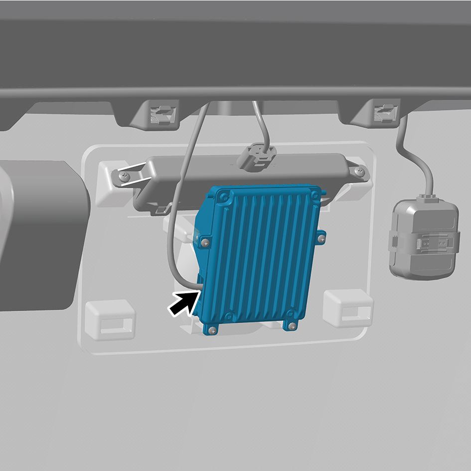
intelligent camera.
6
Remove 4 fixing screws of the front view intelligent
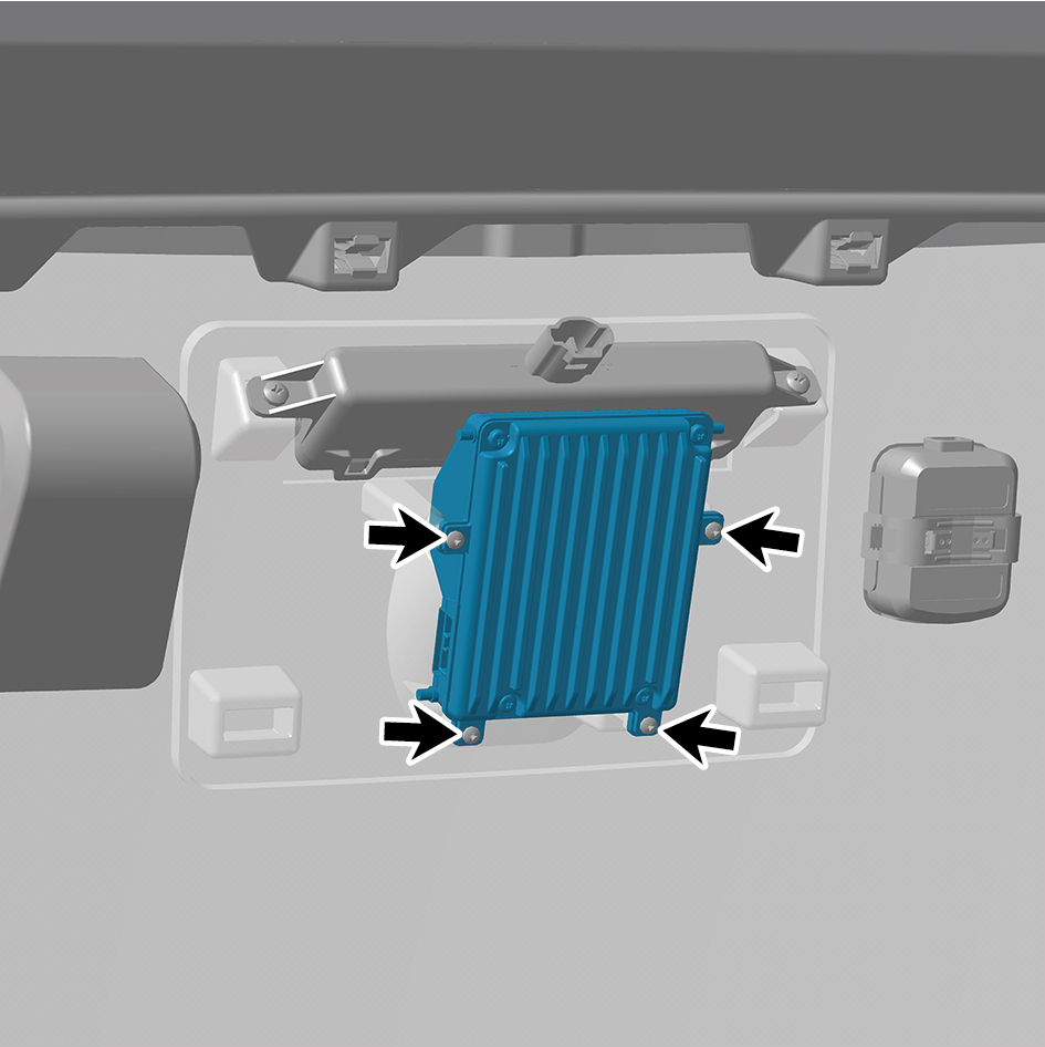
camera.
7
Remove the front view intelligent camera.
Installation Procedures
1
Move the front view intelligent camera to the mounting
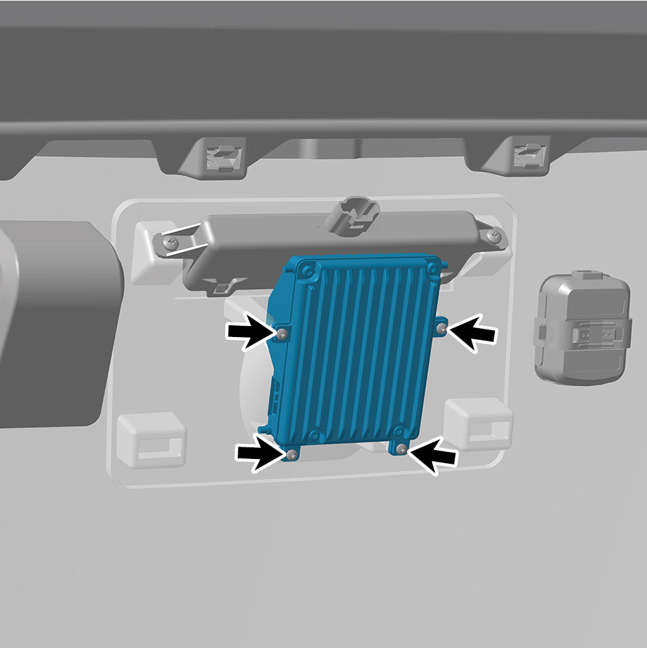
position.
2
Install 4 fixing screws of the front view intelligent camera.
3
Connect 1 harness connector of the front view intelligent
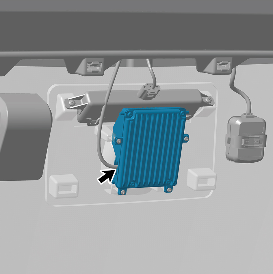
camera.
caution
The harness is firmly connected following the
principal of "insert until a click is heard for
confirmation".
4
Install the front camera trim cover assembly.
5
Connect the battery negative cable.
6
Close the front flip cover plate.
7
Close the door.
caution
After part replacement, it is necessary to recalibrate
the camera.
5.1.5.2 Replacement of Front Millimeter Wave Radar Shield
Radar Shield
Removal Procedures
1
Pry off the Front Millimeter Wave Radar shield.
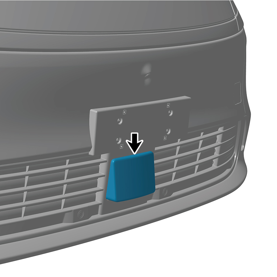
Installation Procedures
1
Install theFront Millimeter Wave Radar shield.
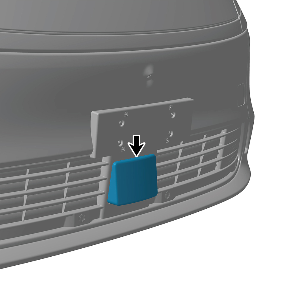
5.1.5.3 Replacement of Front Millimeter Wave Radar
Radar
Removal Procedures
1
Open the door.
2
Open the front flip cover plate.
3
Disconnect the battery negative cable.
caution
power down the high-voltage system before
disconnecting the negative pole of the storage
battery.
4
Remove the Front millimeter wave radar radar shield.
5
Disconnect 1 harness connector of the Front millimeter
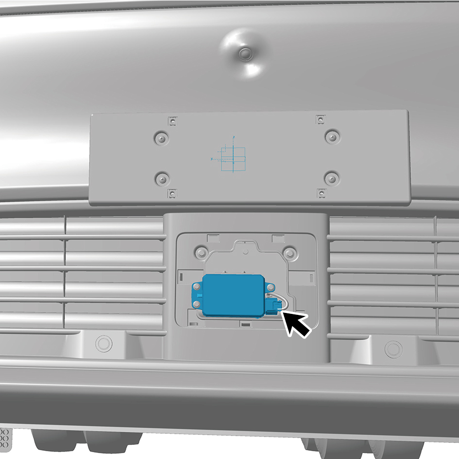
wave radar.
6
Remove 3 fixing bolts of the Front millimeter wave radar.
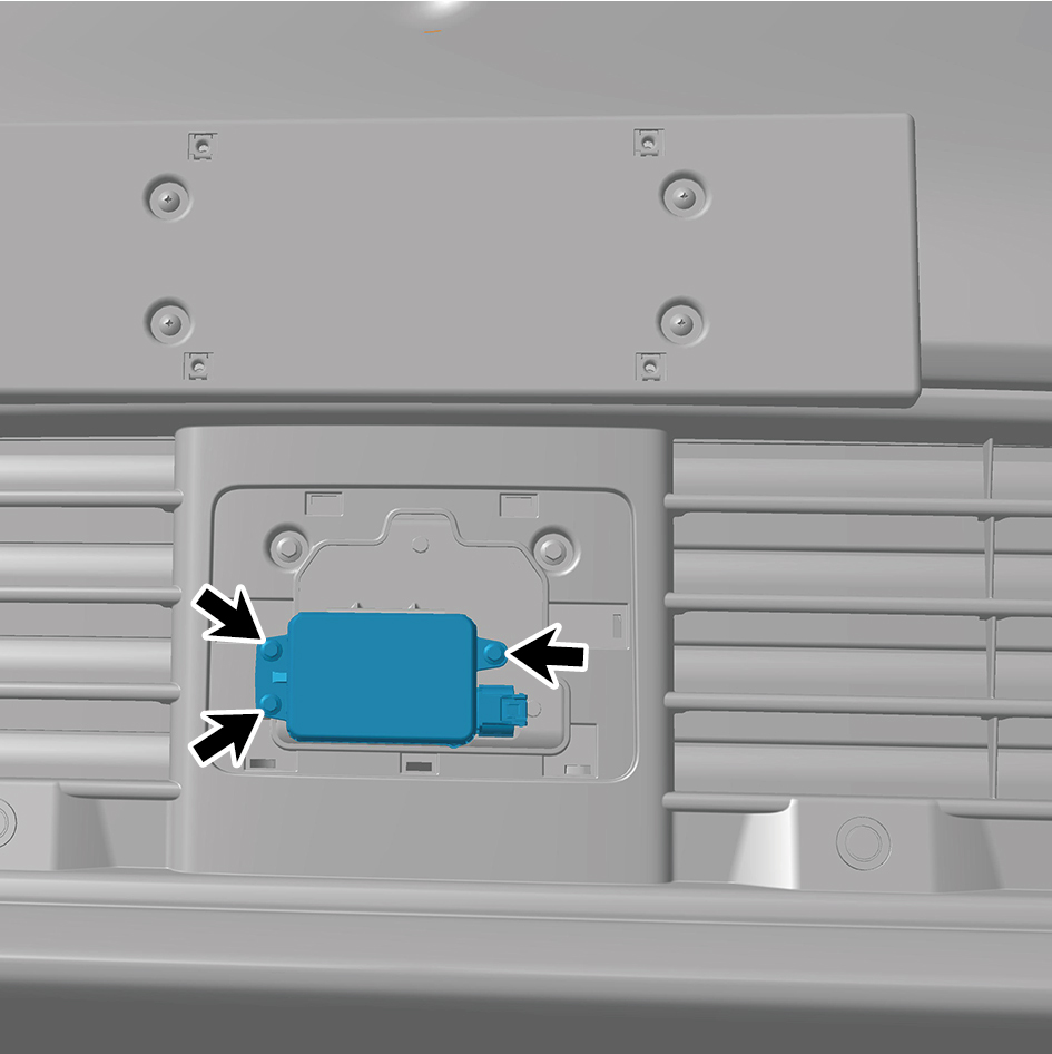
7
Remove the Front millimeter wave radar.
Installation Procedures
1
Move the Front millimeter wave radar to the mounting
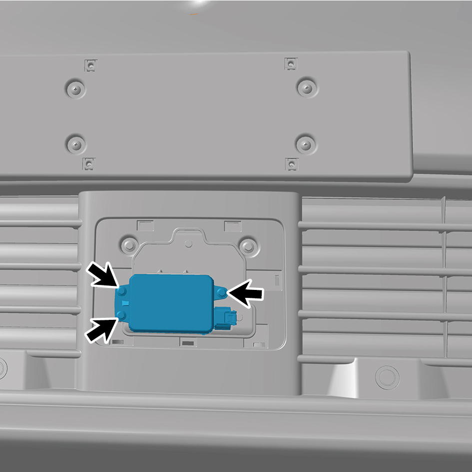
position.
2
Install 3 fixing bolts of the Front millimeter wave radar.
Torque:(4 ft-lb +/- .75 ft-lb) ft-lb
3
Connect 1 harness connector of the Front millimeter wave
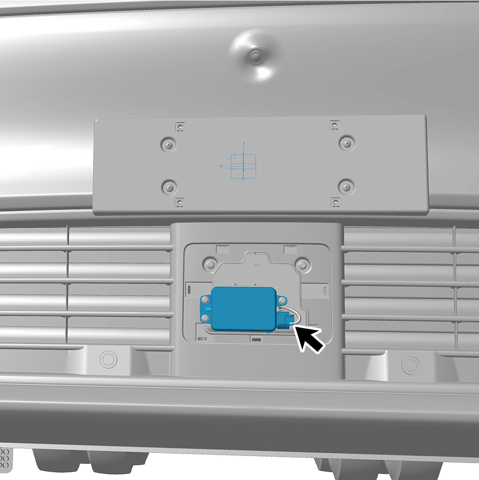
radar.
caution
The harness is firmly connected following the
principal of "insert until a click is heard for
confirmation".
4
Install the Front millimeter wave radar radar shield.
5
Connect the battery negative cable.
6
Close the front flip cover plate.
7
Close the door.
caution
After part replacement, it is necessary to recalibrate
the radar.
5.1.5.4 Replacement of MMWRL
Removal
Procedures
1
Open the door.
2
Open the front flip cover plate.
3
Disconnect the battery negative cable.
caution
power down the high-voltage system before
disconnecting the negative pole of the storage
battery.
4
Remove the left side wall lower trim panel assembly.
5
Remove the left skirt plate assembly.
6
Remove 4 fixing screws of the MMWRL.
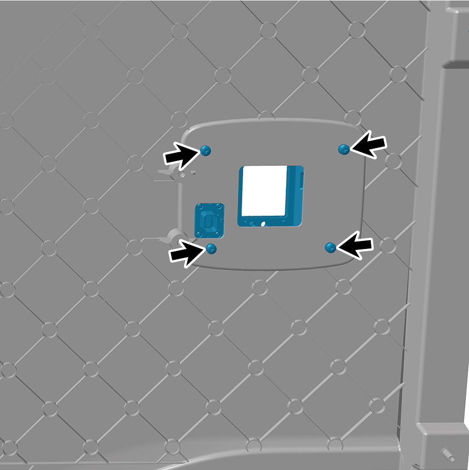
7
Remove the MMWRL cover.
Installation
Procedures
1
Move the MMWRL c o v e r to the mounting position.
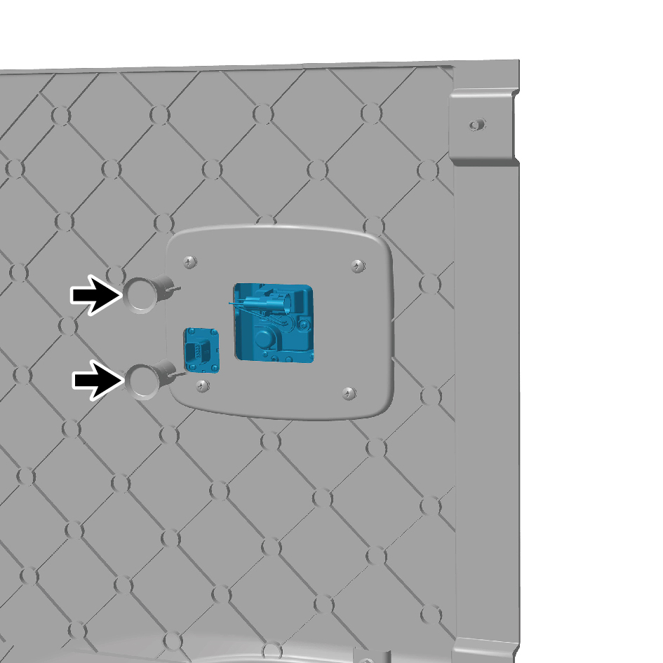
2
Install the rubber buffer pad and then install the four fixing
screws of the millimeter wave radar on the left side.
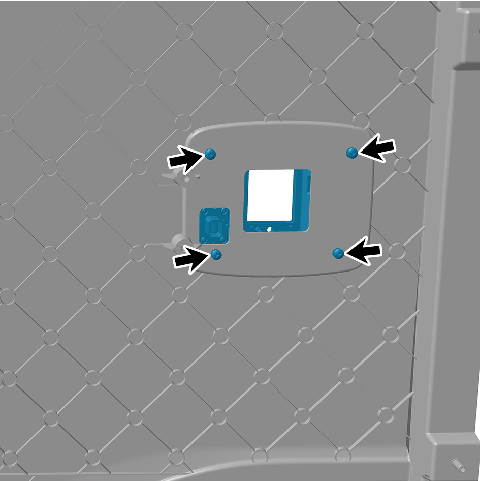
3
Install the left skirt plate assembly.
4
Install the left side wall lower trim panel assembly.
5
Connect the battery negative cable.
6
Close the front flip cover plate.
7
Close the door.
caution
After part replacement, it is necessary to recalibrate
the radar.
5.1.5.5 Replacement of MMWRR
Removal
Procedures
1
Open the door.
2
Open the front flip cover plate.
3
Disconnect the battery negative cable.
caution
power down the high-voltage system before
disconnecting the negative pole of the storage
battery.
4
Remove the right side wall lower trim panel assembly.
5
Remove the right skirt plate assembly.
6
Remove 4 fixing screws of the MMWRR.
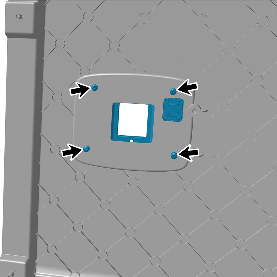
7
Remove the MMWRR cover.
Installation
Procedures
1
Move the MMWRR c o v e r to the mounting position.
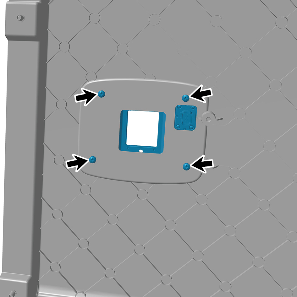
2
Install the rubber buffer pad and then install the four fixing
screws of the millimeter wave radar on the right side.
3
Install the right skirt plate assembly.
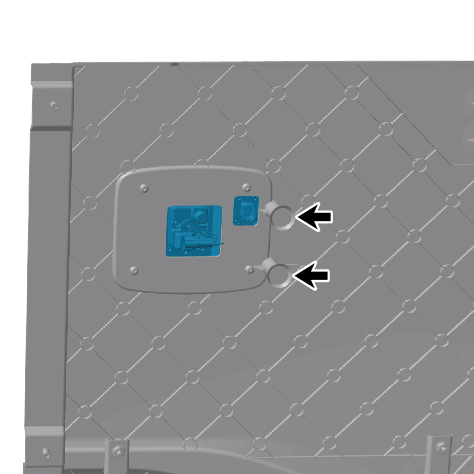
4
Attach the right side wall lower trim panel assembly.
5
Connect the battery negative cable.
6
Close the front flip cover plate.
7
Close the door.
caution
After part replacement, it is necessary to recalibrate
the radar.
5.1.5.6 Replacement of Main USS
Removal Procedures
1
Open the door.
2
Open the front flip cover plate.
3
Disconnect the battery negative cable.
caution
power down the high-voltage system before
disconnecting the negative pole of the storage
battery.
4
Remove the engine compartment trim panel body.
5
Remove the through-type lamp.
6
Remove the front MMW radar shield.
7
Remove the forward MMW radar.
8
Remove the front MMW radar adapter bracket.
9
Remove the left cover plate of the corner radar.
10
Remove the right cover plate of the corner radar.
11
Remove the front bumper assembly.
12
Disconnect 1 harness connector of the USS.
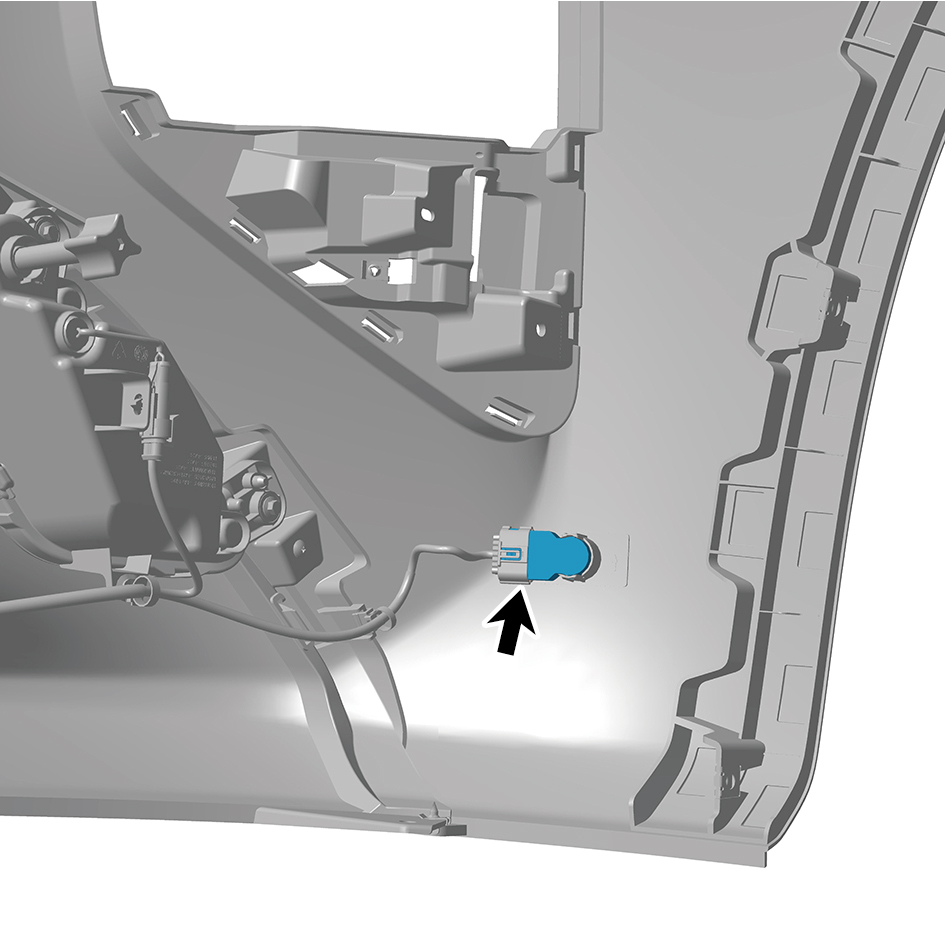
13
Remove the USS.
Installation Procedures
1
Move the Main USS to the mounting position.
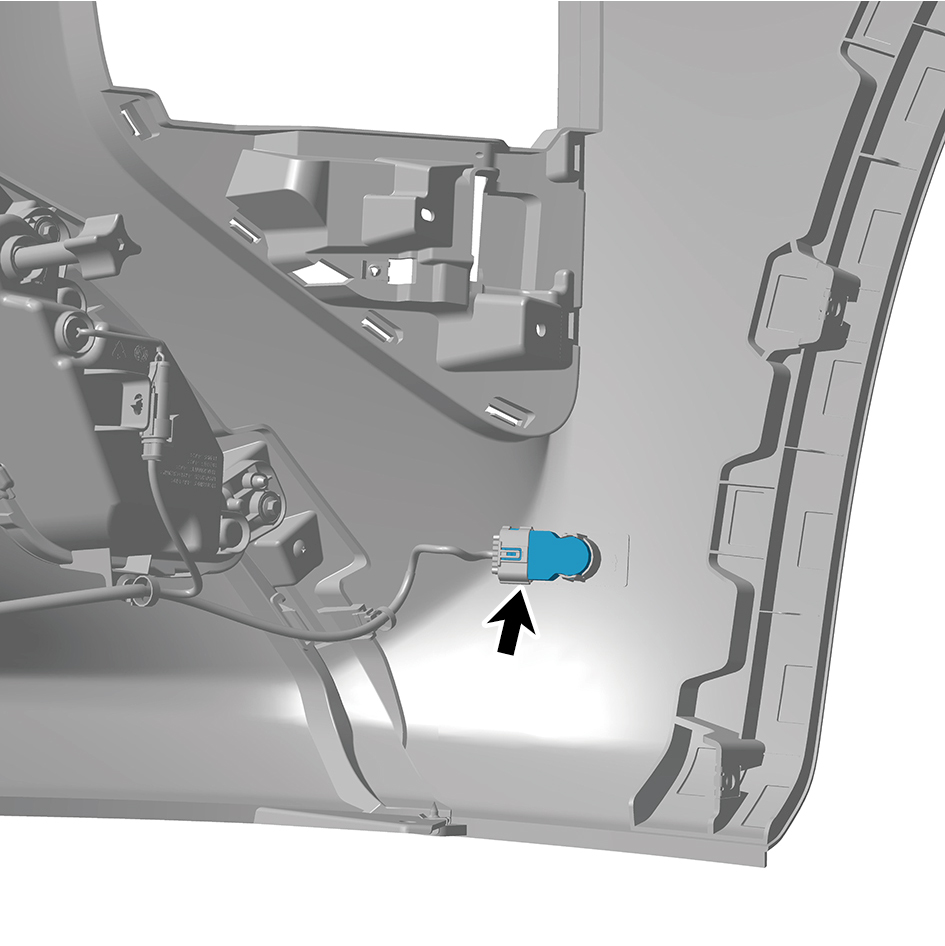
2
Connect 1 harness connector of the USS .
caution
The harness is firmly connected following the
principal of "insert until a click is heard for
confirmation".
3
Install the front bumper assembly.
4
Install the right cover plate of the corner radar.
5
Install the left cover plate of the corner radar.
6
Install the front MMW radar adapter bracket.
7
Install the forward MMW radar.
8
Install the front MMW radar shield.
9
Install the through-type lamp.
10
Install the engine compartment trim panel body.
11
Connect the battery negative cable.
12
Close the front flip cover plate.
13
Close the door.
5.1.5.7 Replacement of Sub USS (matte black)
Removal Procedures
1
Open the door.
2
Open the front flip cover plate.
3
Disconnect the battery negative cable.
caution
power down the high-voltage system before
disconnecting the negative pole of the storage
battery.
4
Remove the engine compartment trim panel body.
5
Remove the through-type lamp.
6
Remove the front MMW radar shield.
7
Remove the forward MMW radar.
8
Remove the front MMW radar adapter bracket.
9
Remove the left cover plate of the corner radar.
10
Remove the right cover plate of the corner radar.
11
Remove the front bumper assembly.
12
Remove the right intake grille assembly.
13
Remove the left intake grille assembly.
14
Disconnect 1 harness connector of the Sub USS (matte
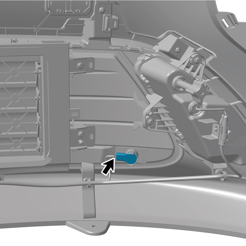
black).
15
Remove the Sub USS (matte black).
Installation Procedures
1
Move the Sub USS (matte black) to the mounting position.
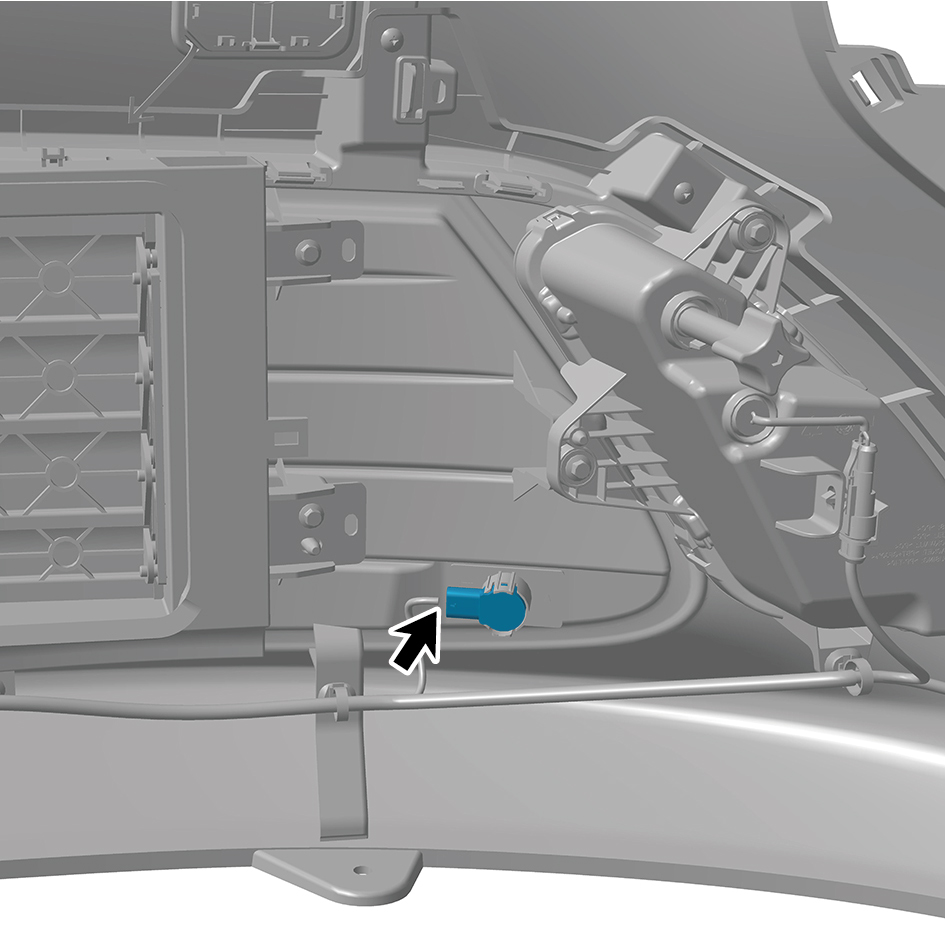
2
Connect 1 harness connector of the Sub USS (matte
black).
caution
The harness is firmly connected following the
principal of "insert until a click is heard for
confirmation".
3
Install the right intake grille assembly.
4
Install the left intake grille assembly.
5
Install the front bumper assembly.
6
Install the right cover plate of the corner radar.
7
Install the left cover plate of the corner radar.
8
Install the front MMW radar adapter bracket.
9
Install the forward MMW radar.
10
Install the front MMW radar shield.
11
Install the through-type lamp.
12
Install the engine compartment trim panel body.
13
Connect the battery negative cable.
14
Close the front flip cover plate.
15
Close the door.
5.1.5.8 Replacement of Left Side USS
Removal Procedures
1
Open the door.
2
Open the front flip cover plate.
3
Disconnect the battery negative cable.
caution
power down the high-voltage system before
disconnecting the negative pole of the storage
battery.
4
Remove the engine compartment trim panel body.
5
Remove the through-type lamp.
6
Remove the front MMW radar shield.
7
Remove the forward MMW radar.
8
Remove the front MMW radar adapter bracket.
9
Remove the left cover plate of the corner radar.
10
Remove the right cover plate of the corner radar.
11
Remove the front bumper assembly.
12
Disconnect 1 harness connector of the left side USS.
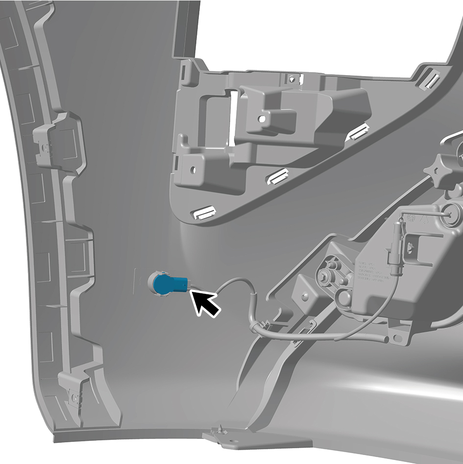
13
Remove the left side USS.
Installation Procedures
1
Move the left side USS to the mounting position.
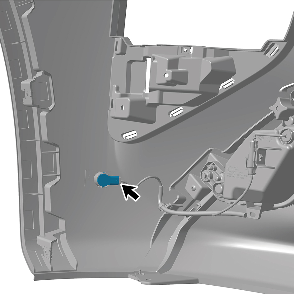
2
Connect 1 harness connector of the left side USS.
caution
The harness is firmly connected following the
principal of "insert until a click is heard for
confirmation".
3
Install the front bumper assembly.
4
Install the right cover plate of the corner radar.
5
Install the left cover plate of the corner radar.
6
Install the front MMW radar adapter bracket.
7
Install the forward MMW radar.
8
Install the front MMW radar shield.
9
Install the through-type lamp.
10
Install the engine compartment trim panel body.
11
Connect the battery negative cable.
12
Close the front flip cover plate.
13
Close the door.