← Back to Contents
4 New Energy Vehicle Components / 4.5 Battery Thermal Management Device | PDF pages 290-304
4.5 Battery Thermal Management Device
4.5 Battery Thermal Management Device
4.5 Battery Thermal Management
Device
4.5.1 Specifications
4.5.1.1 Fastener Specifications
Range Of Torque
Fastener Specifications
Specifications
Metric System(ft-lb)
Fixed bolts connecting the bottom of the
thermal management unit to the
(18 ft-lb +/- 2 ft-lb) ft-lb
M8
integrated framework
Fixed nuts connecting the bottom of the
thermal management unit to the
(18 ft-lb +/- 2 ft-lb) ft-lb
M8
integrated framework
Fixed bolts connecting the side of the
thermal management unit to the
(18 ft-lb +/- 2 ft-lb) ft-lb
M8
integrated frame
The fixing bolt connecting the left
battery pack connector bracket to the
M14
103 ft-lb +/- 7 ft-lb
frame assembly
The fixing nut connecting the left battery
pack connector bracket to the frame
M14
103 ft-lb +/- 7 ft-lb
assembly
Fixed bolts for the connection between
the expansion tank (plastic) and the
M10
52 ft-lb
integrated frame
The fixing nut for the fixed connection
between the expansion tank (plastic)
M8
52 ft-lb
and the integrated frame
4.5.2 Decomposition Diagram
4.5.2.1 Decomposition Diagram
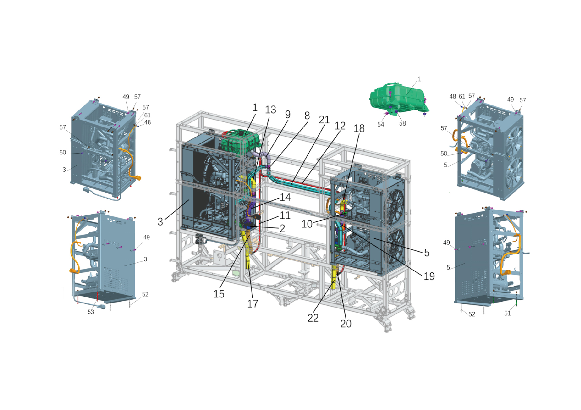
1.
19.
Right Water Filter Inlet Hose
Expansion Tank (Plastic)
2.
20.
Water Filter
Right Water Filter Outlet Hose
3.
21.
Thermal Management Unit-lh
Right Unit Water Replenishment Hos
5.
Thermal Management Unit-rh
22.
Right Unit Inlet Hose
8.
Tee Joint(t25)
48.
Hexagon Flange Bolt
9.
49.
Hexagon Flange Bolt
Expansion Kettle Water Outlet Hose
10.
50.
Hexagon Flange Bolt
Wptc Water Outlet Hose
11.
51.
Hexagon Flange Bolt
Left Unit Exhaust Hose
12.
Right Unit Exhaust Hose
52.
Hexagon Flange Bolt
13.
53.
Hexagon Flange Bolt
Left Chiller Water Outlet Hose
14.
54.
Hexagon Flange Bolt
Left Water Filter Inlet Hose
57.
15.
Hexagon Flange Lock Nut_all Metal
Left Water Filter Outlet Hose
17.
58.
Hexagon Flange Lock Nut_all Metal
Left Unit Inlet Hose
18.
61
Right Chiller Water Outlet Hose
Inside and Out Teeth Serrated Lock
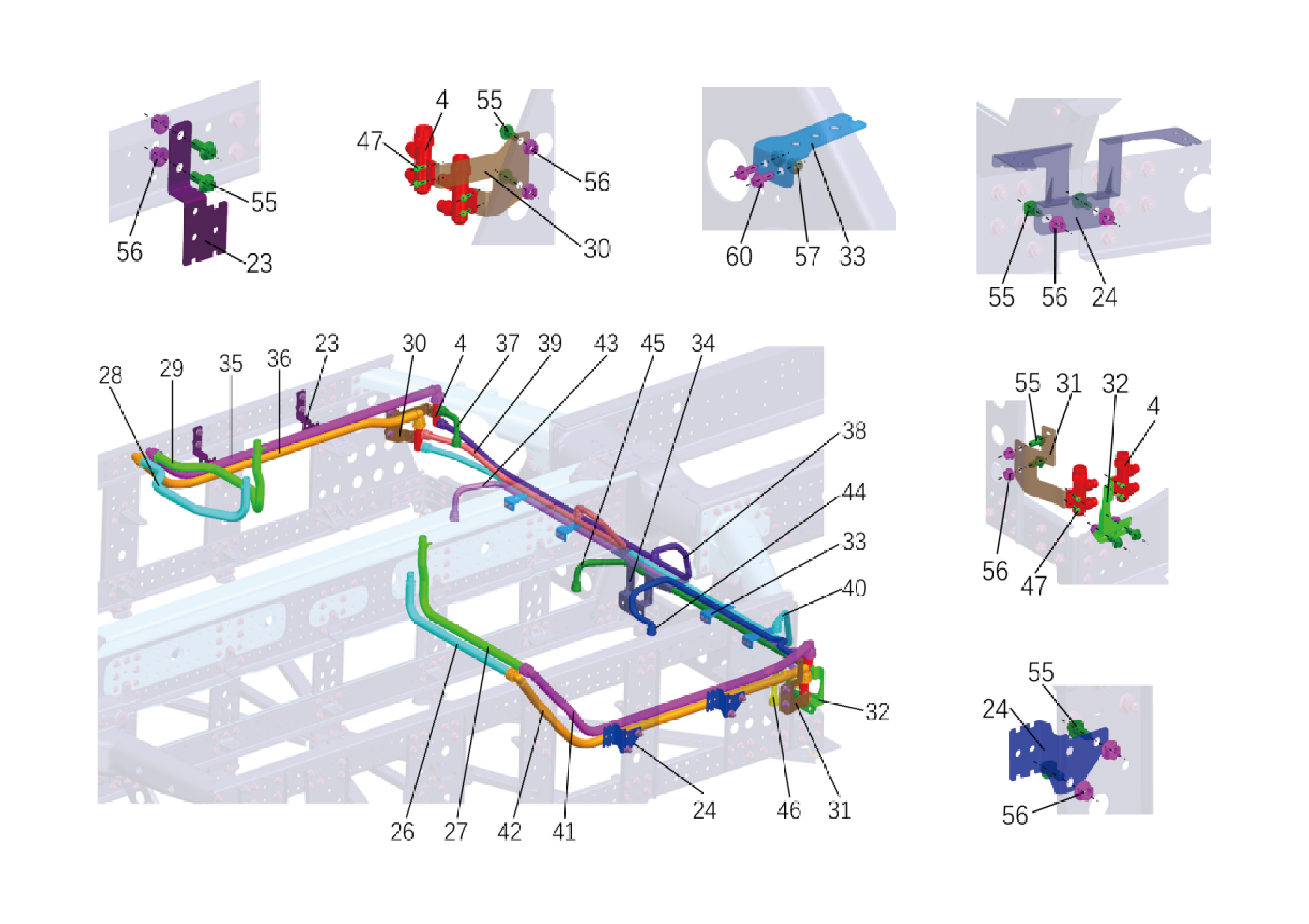
4.
38.
Right 1 Battery Pack Water Inlet n
Three-way Joint for Battery Piping
23.
39.
Fixed Bracket for the Piping of the Left Battery Pack
Left 1 Battery Pack Water Outlet n
24.
40.
Right Battery Pack Line Fixing Bra
Right 1 Battery Pack Water Outlet
26.
41.
Right Unit Inlet Nylon Pipe
Water Inlet Nylon Tube of the Lower Battery Pack
27.
42.
Right Unit Water Outlet Nylon Pipe
Water Outlet Nylon Tube of the Lower Battery Pack
28.
43.
Left Unit Inlet Nylon Pipe
Left 2 Battery Pack Water Inlet Ny
29.
44.
Right 2 Battery Pack Water Inlet n
Left Unit Water Outlet Nylon Pipe
30.
45.
Left Battery Pack Connector Fixing
Left 2 Battery Pack Water Outlet n
31.
46.
Right Battery Pack Connector Fixin 1
Right 2 Battery Pack Water Outlet
32.
47.
Hexagon Flange Bolt
Right Battery Pack Connector Fixin 2
55.
33.
Battery Pack Pipeline Fixing Brack 1
Hexagon Flange Bolt
34.
56.
Battery Pack Pipeline Fixing Brack 2
Hexagon Flange Nut
57.
35.
Hexagon Flange Lock Nut_all Metal
Water Inlet Nylon Tube of the Upper Battery Pack
36.
60.
Hexagon Flange Bolt
Water Outlet Nylon Tube of the Upper Battery Pack
37.
Left 1 Battery Pack Water Inlet Ny
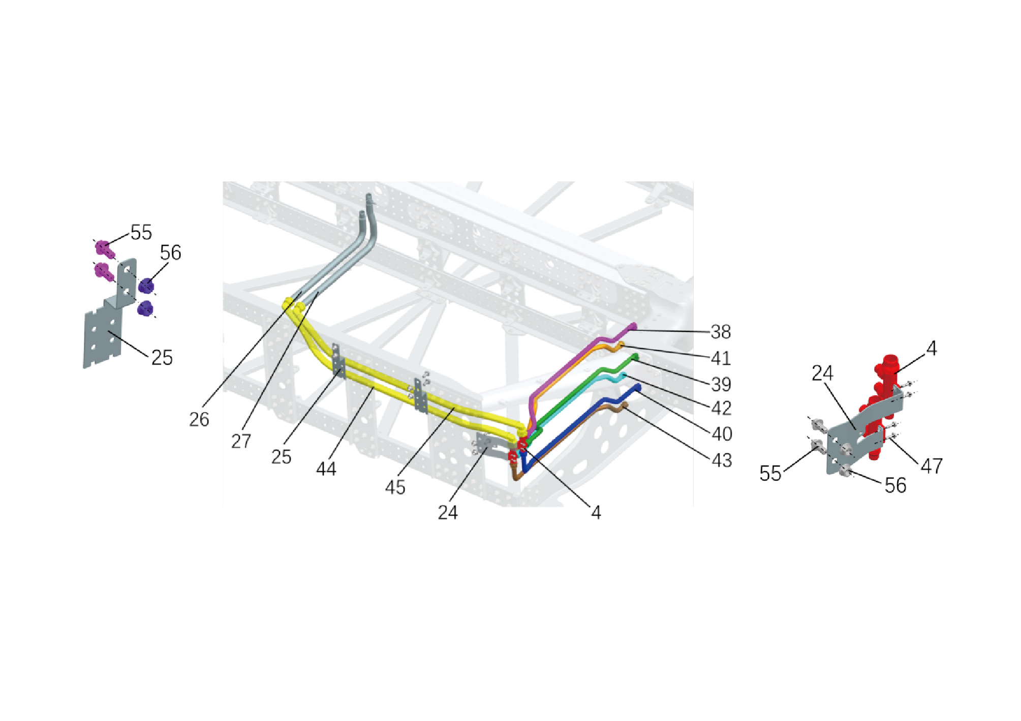
4.
41.
Battery Pipeline 4-Way Connector
Right 1 Battery Pack Water Outlet
24.
42.
Right Battery Pack Connector Fixin
Right 2 Battery Pack Water Outlet
25.
Right Battery Pack Line Fixing Bra
43.
Right 3 Battery Pack Water Outlet
26.
Right Unit Inlet Nylon Pipe
44.
Right Battery Pack Water Outlet Ny
27.
45.
Right Battery Pack Water Inlet Nyl
Right Unit Water Outlet Nylon Pipe
38.
Right 1 Battery Pack Water Inlet n
47.
Hexagon Flange Bolt
55.
39.
Right 2 Battery Pack Water Inlet n
Hexagon Flange Bolt
40.
56.
Right 3 Battery Pack Water Inlet n
Hexagon Flange Nut
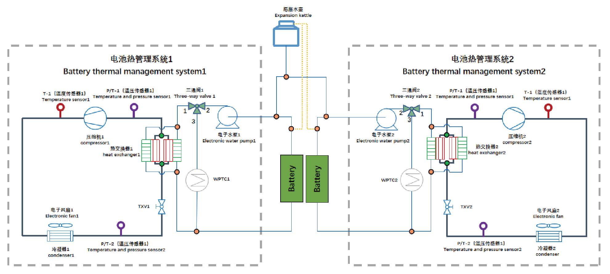
4.5.3 The Working Principle of the System
4.5.3.1 System Working Principle
4.5.4 Dismantling and Installation
4.5.4.1 Replacement of the Thermal Management Unit (left)
Management Unit (left)
Removal Procedures
1
Release air pressure from the brake system.
2
Open the door.
3
Open the front flip cover plate.
4
Disconnect the battery negative cable.
5
Perform power-off of high voltage system.
6
Drain coolant from battery thermal management system.
7
Remove the back integrated bracket side cover plate
assembly (left).
8
Remove the back integrated bracket side cover plate
assembly (right).
9
Remove the back integrated bracket middle cover plate
assembly.
10
Remove the back integrated bracket upper cover plate
filler cap.
11
Remove the back integrated bracket upper cover plate.
12
Remove the left deflector lower body.
13
Remove the expansion tank (plastic) (left).
14
Remove the water filter.
15
Remove the rear working lamp.
16
Remove the 4 fixing bolts of the bracket.
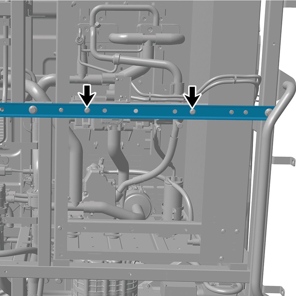
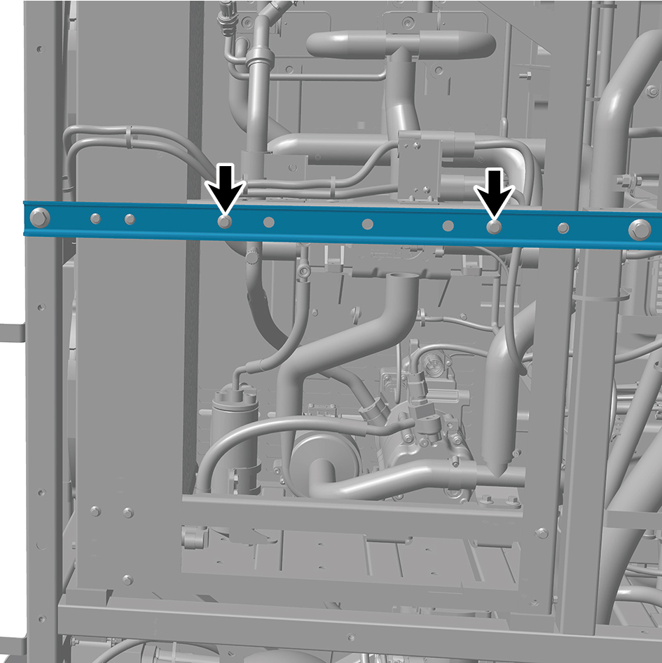
17
Remove the 4 fixing bolts of the bracket.
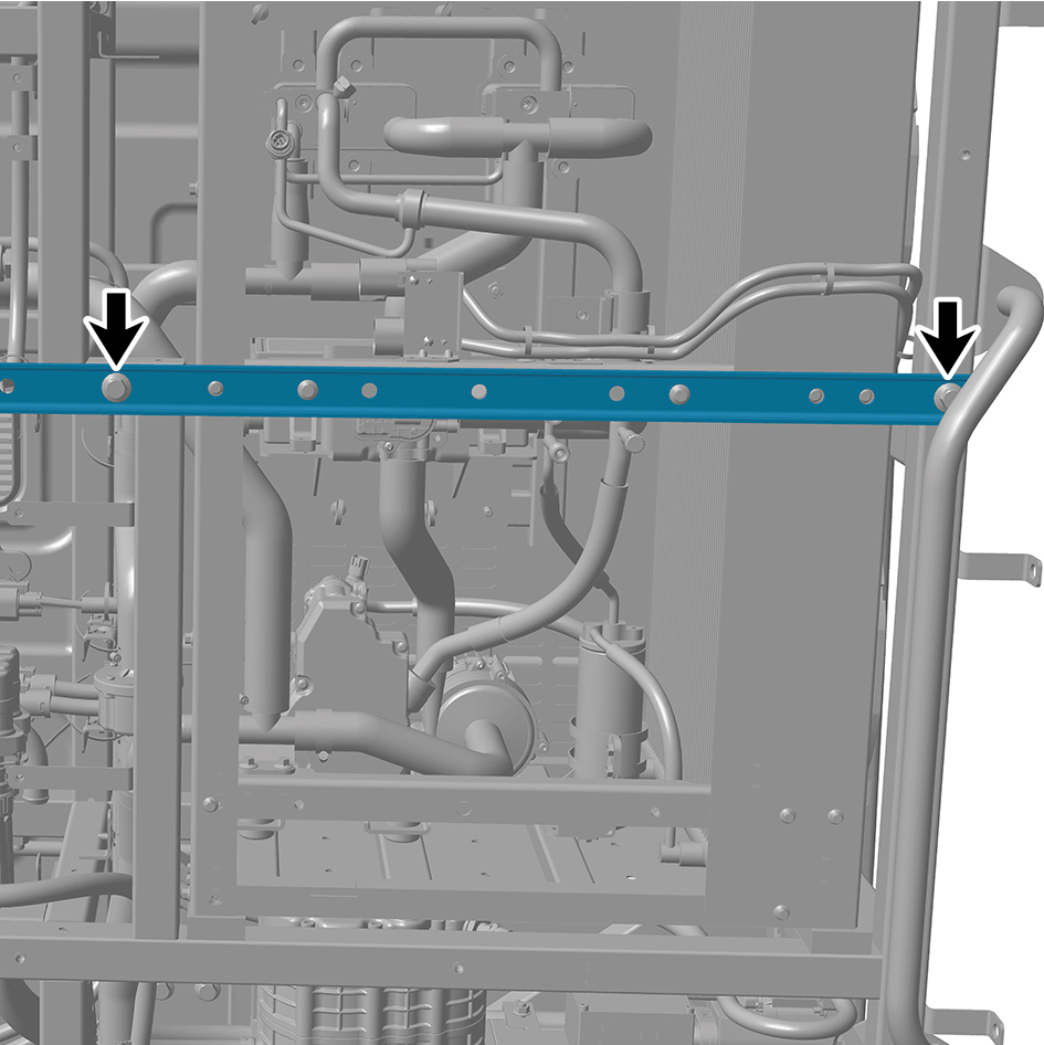
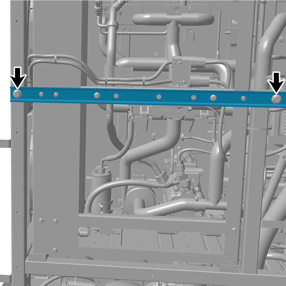
18
Remove the 3 fixing nuts of the bracket.
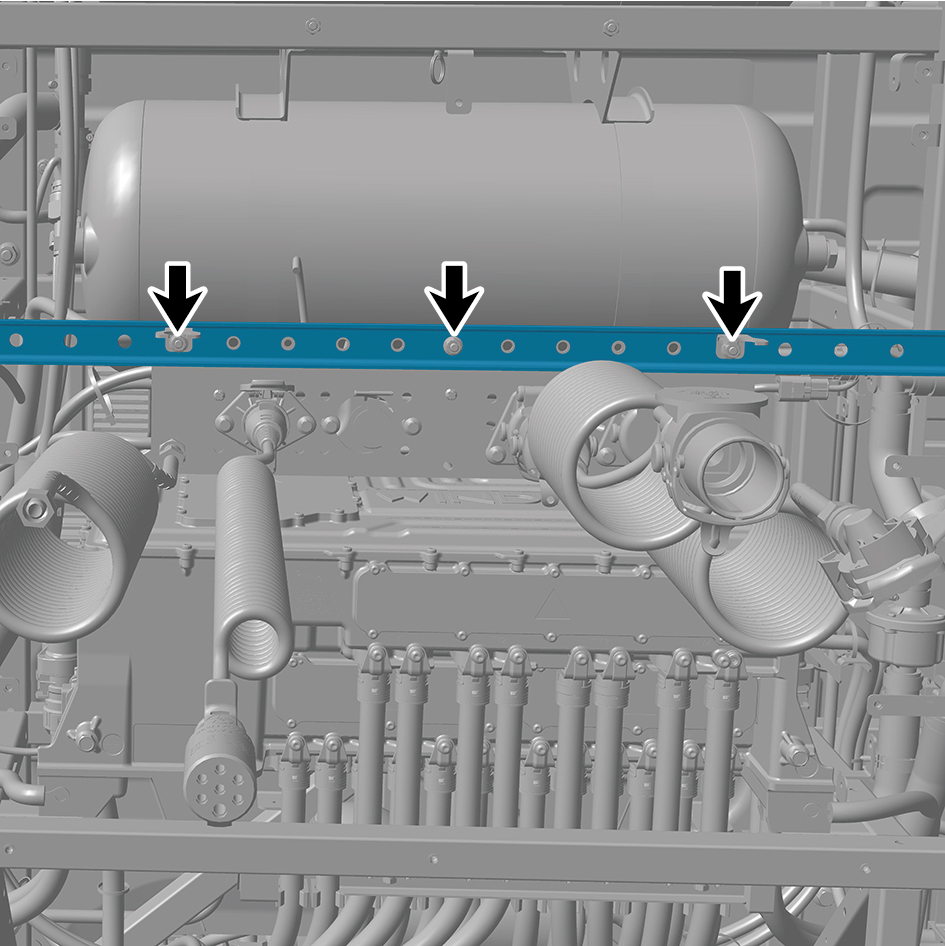
19
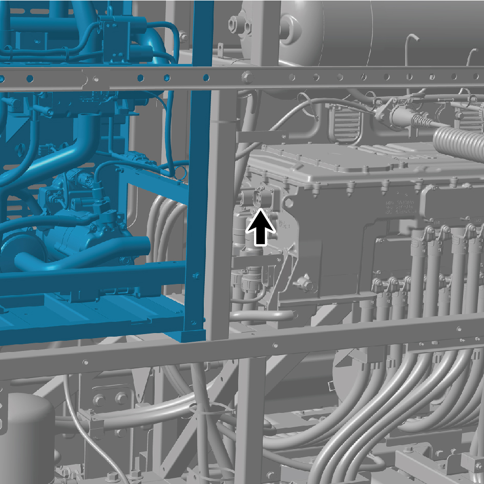
Disconnect the 2 harness connectors of the thermal
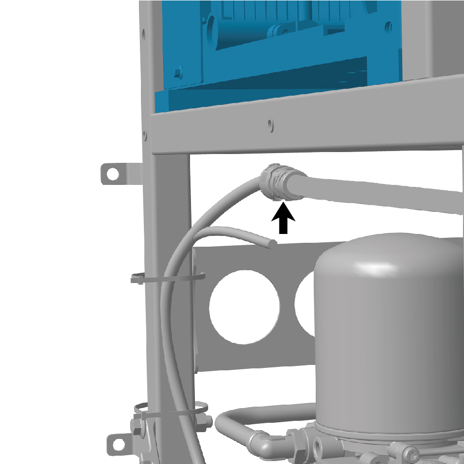
management unit (left).
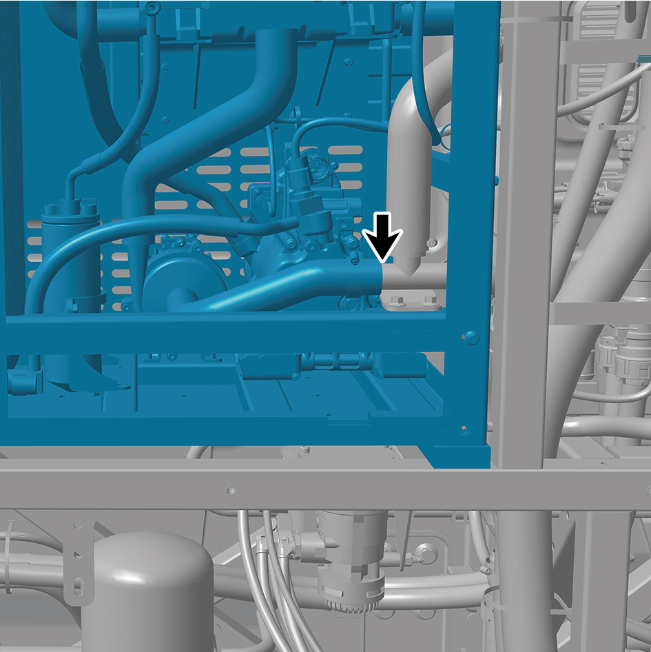
20
Disconnect the 3 water pipes of the thermal management
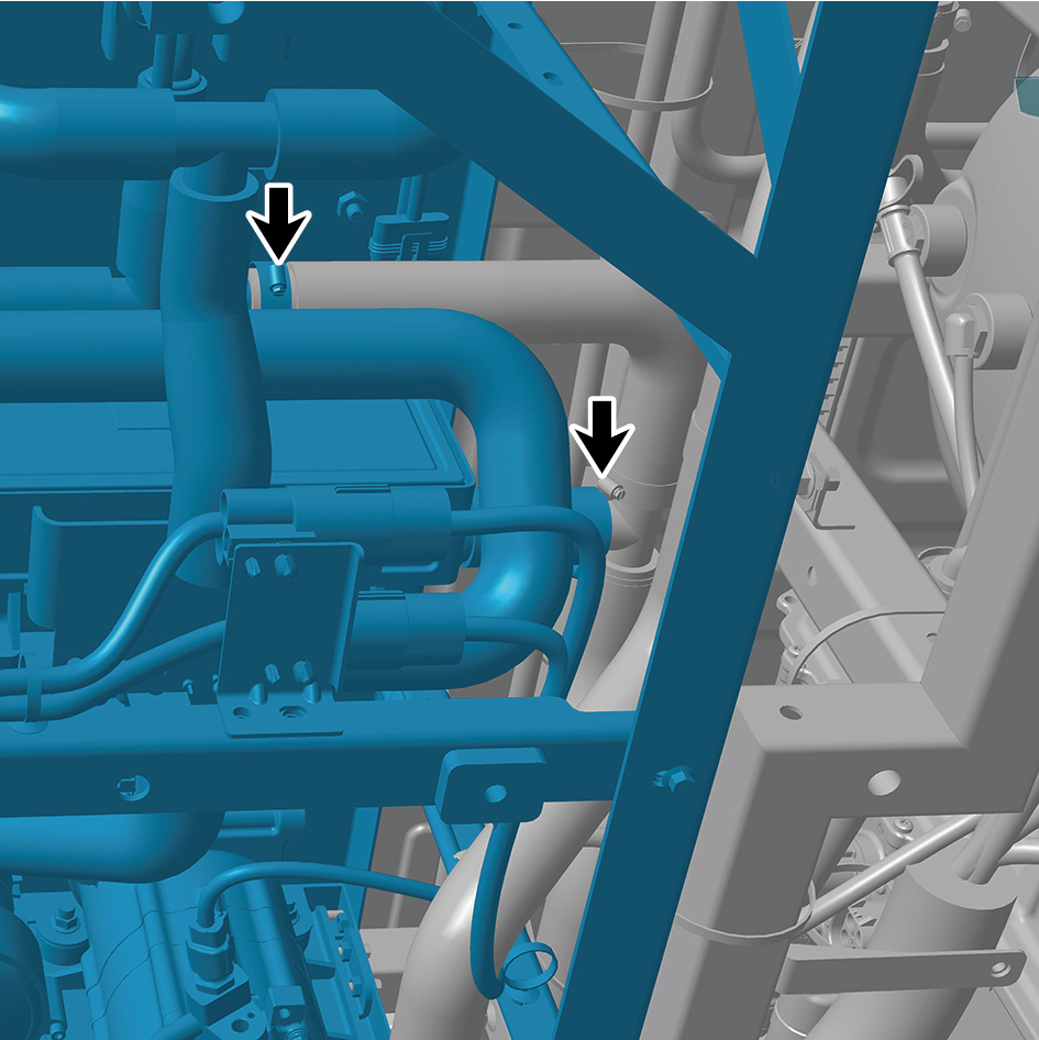
unit (left).
caution
Use a clean container to receive the discharged
coolant.
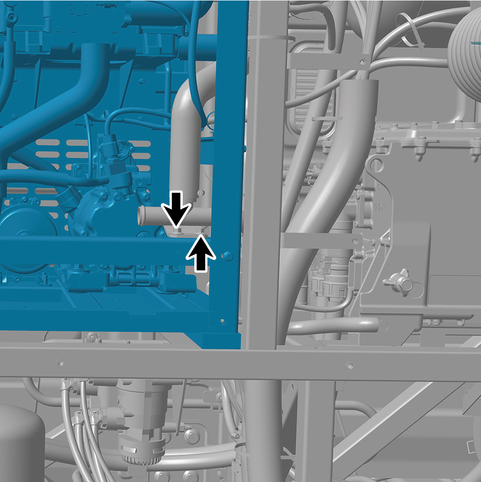
21
Remove the 2 fixing bolts of the water pipe.
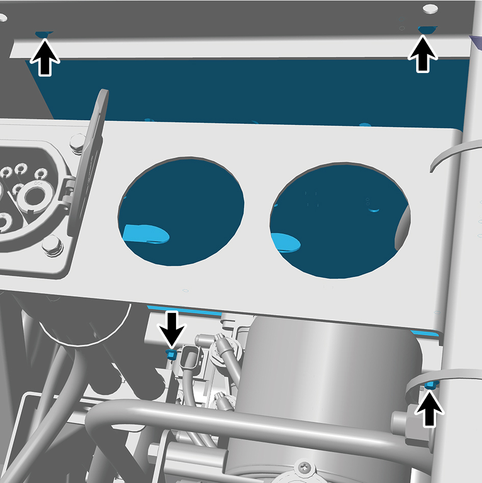
22
Remove the 12 fixing bolts and nuts of the thermal
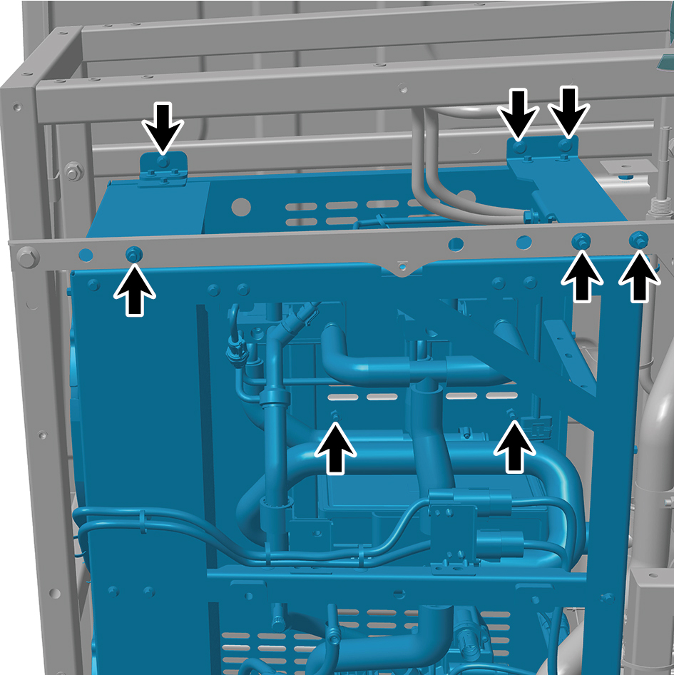
management unit (left) and detach the thermal
management unit (left).
Installation Procedures
1
Move the thermal management unit (left) to the installation
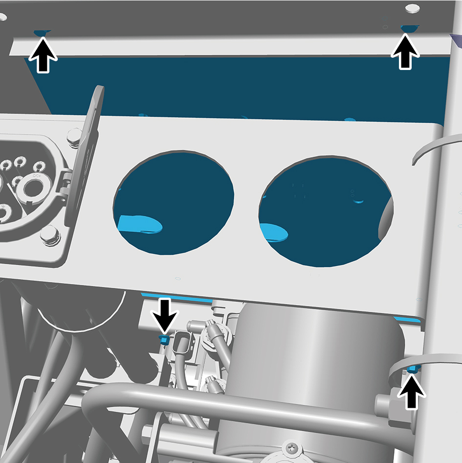
position.
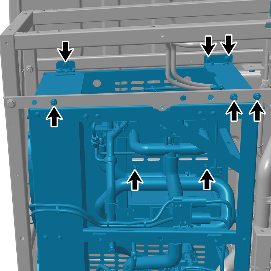
2
Install the 12 fixing bolts and nuts of the thermal
management unit (left).
Torque: (18 ft-lb +/- 2 ft-lb) ft-lb
3
Install the 2 fixing bolts of the water pipe.
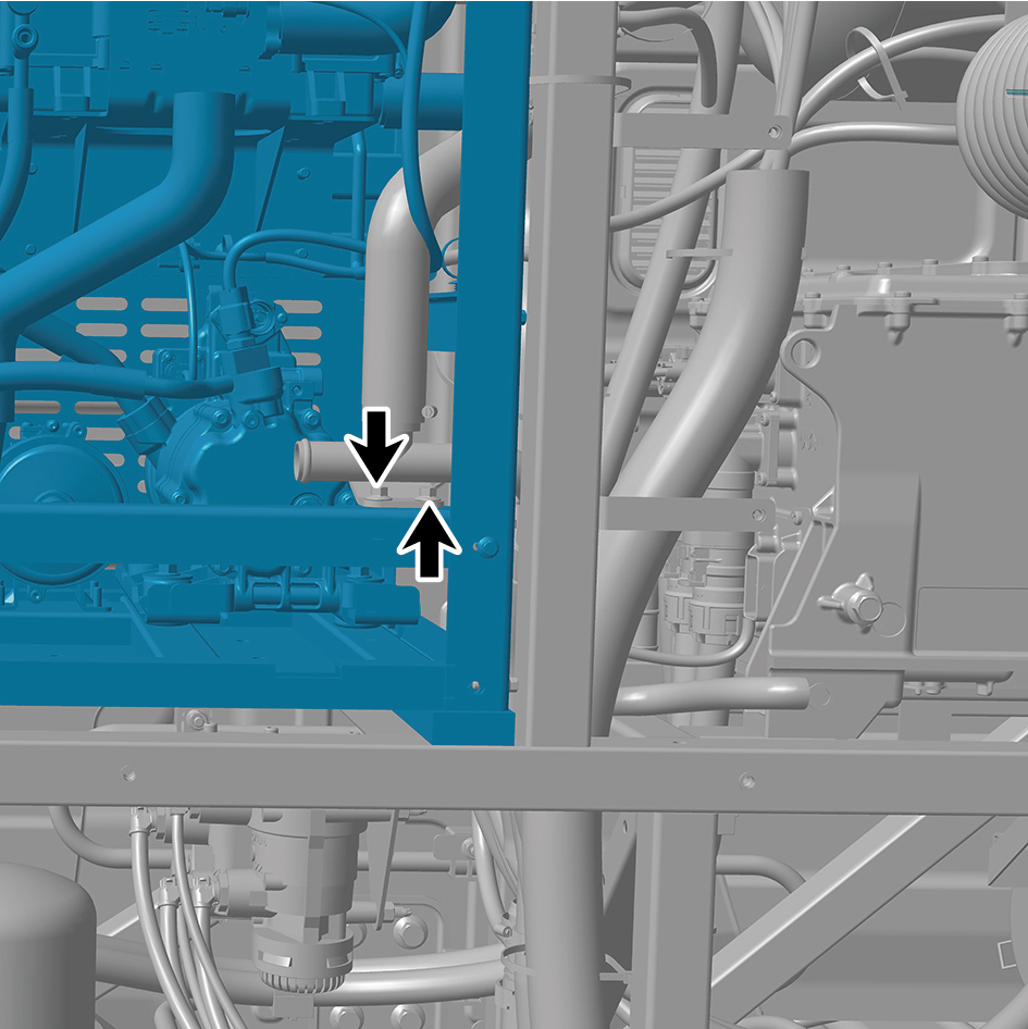
Torque: (18 ft-lb +/- 2 ft-lb) ft-lb
4
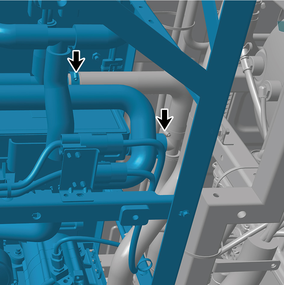
Connect the 3 water pipes of the thermal management
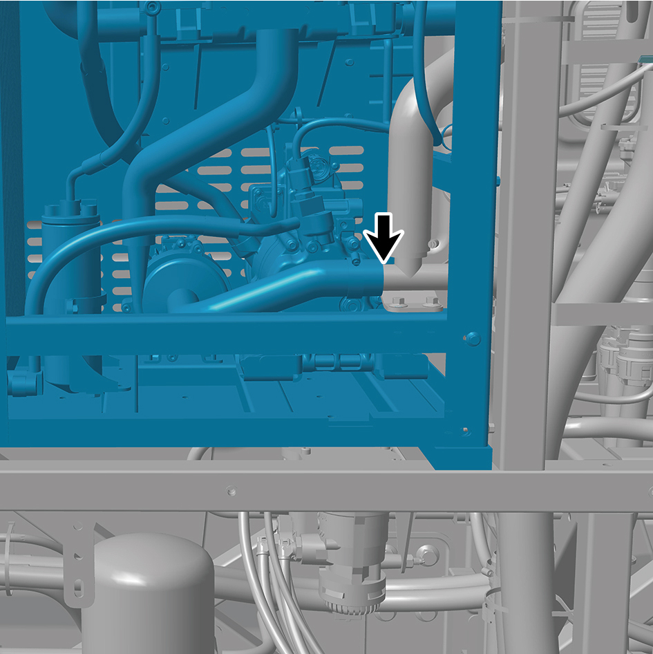
unit (left).
5
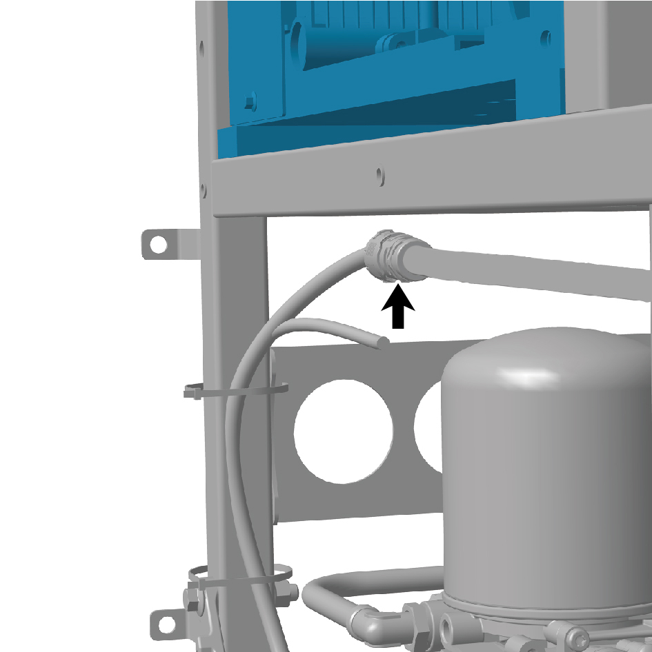
Connect the 2 harness connectors of the thermal
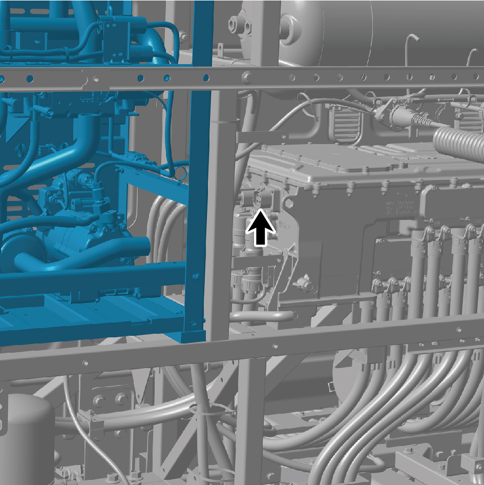
management unit (left).
caution
The harness is firmly connected following the
principal of "insert until a click is heard for
confirmation".
6
Install the 3 fixing nuts of the bracket.
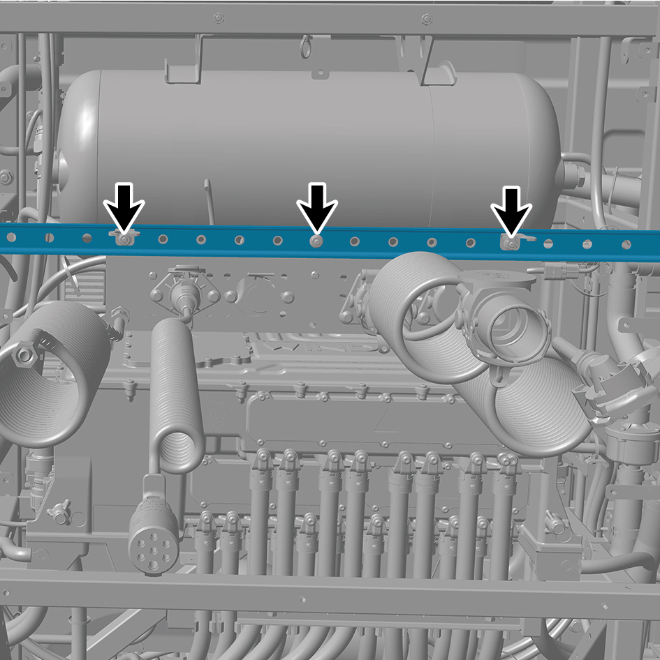
Torque: (18 ft-lb +/- 2ft-lb) ft-lb
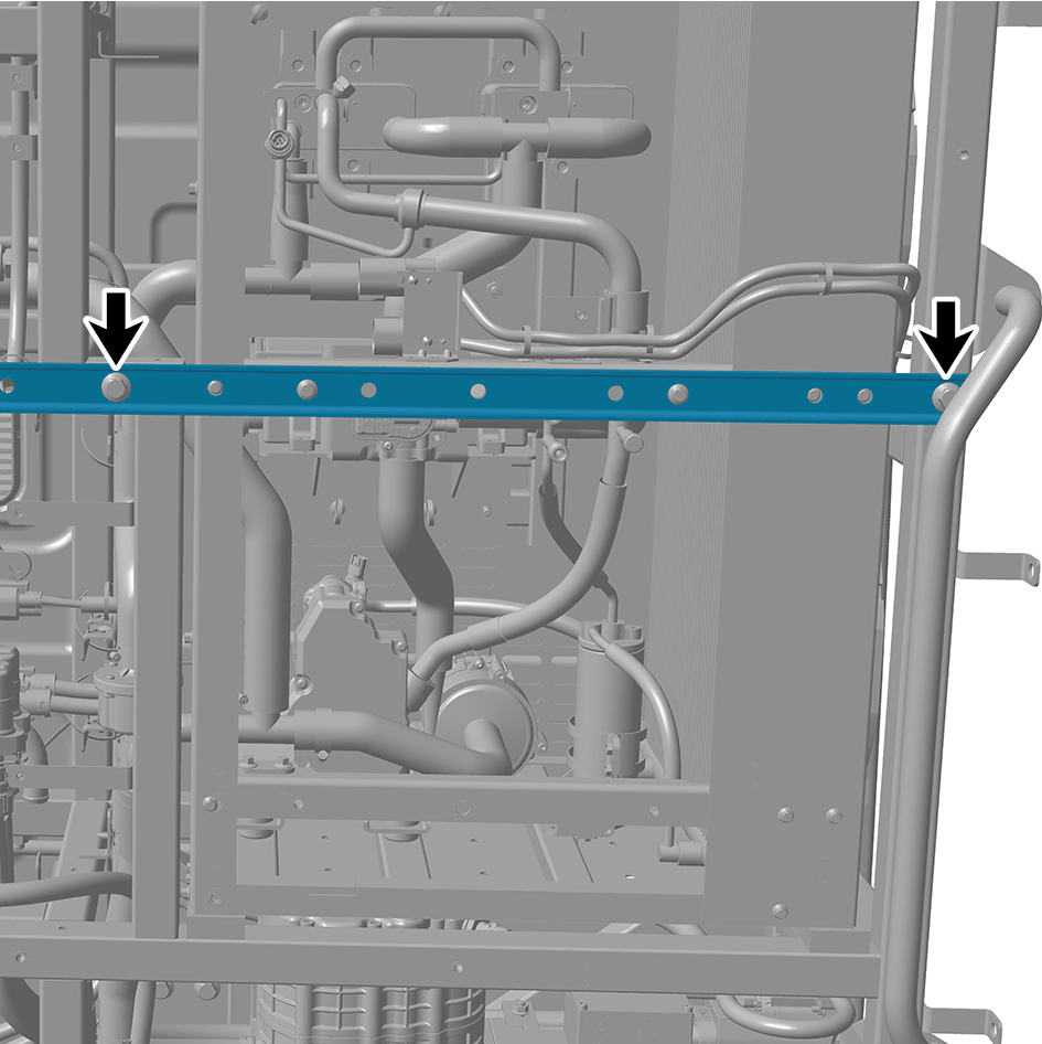
7
Install the 4 fixing bolts of the bracket.
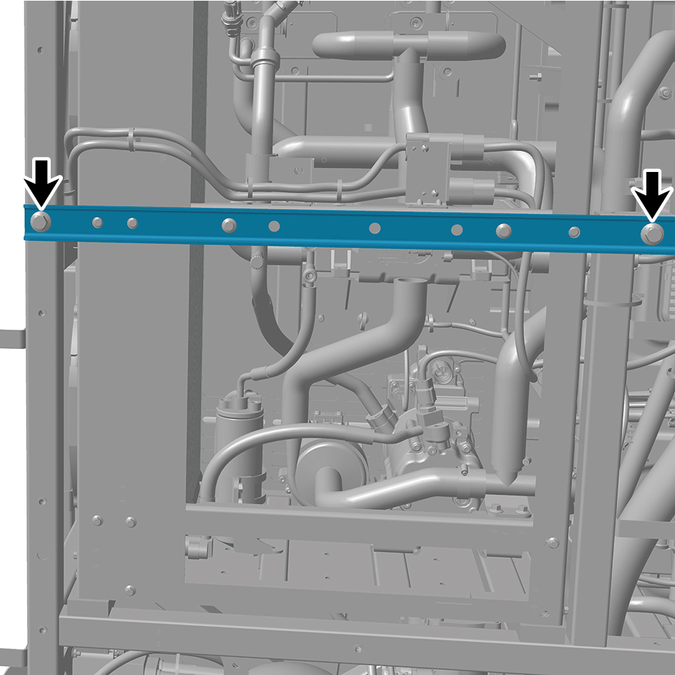
Torque: (88 ft-lb +/- 6 ft-lb) ft-lb
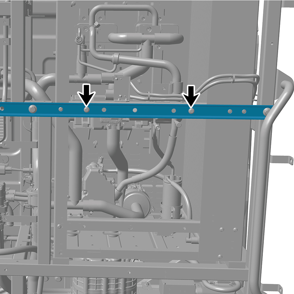
8
Install the 4 fixing bolts of the bracket.
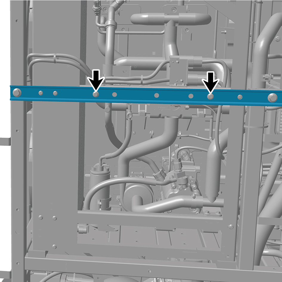
Torque: (18 ft-lb +/- 2 ft-lb) ft-lb
9
Install the rear working lamp.
10
Install the water filter.
11
Install the expansion tank (plastic) (left).
12
Install the left deflector lower body.
13
Install the back integrated bracket upper cover plate.
14
Install the back integrated bracket upper cover plate filler
cap.
15
Install the back integrated bracket middle cover plate
assembly.
16
Install the back integrated bracket side cover plate
assembly (right).
17
Install the back integrated bracket side cover plate
assembly (left).
18
Fill coolant in the battery thermal management system.
19
Perform power-on of the high voltage system.
20
Connect the battery negative cable.
21
Close the front flip cover plate.
22
Close the door.