← Back to Contents
4 New Energy Vehicle Components / 4.4 Power System Cooling Device | PDF pages 264-289
4.4 Power System Cooling Device
4.4 Power System Cooling Device
4.4.1 Specifications
4.4.1.1 Fastener Specifications
Range Of Torque
Specifications
Fastener name
Metric System(ft-lb)
The fixing bolt connecting the fixed
bracket of the water pump and the
M8
18 ft-lb +/- 2 ft-lb
electronic water pump
The fixing nut connecting the fixed
bracket of the water pump and the
M8
18 ft-lb +/- 2 ft-lb
electronic water pump
Fixed bolts connecting the expansion
tank (plastic) to the rear integrated
M10
28 ft-lb - 38 ft-lb
frame (unit) (plastic)
The fixing bolts connecting the front-end
M12
66 ft-lb +/- 3.5 ft-lb
module and the front connecting beam
4.4.2 Decomposition Diagram
4.4.2.1 Decomposition Diagram
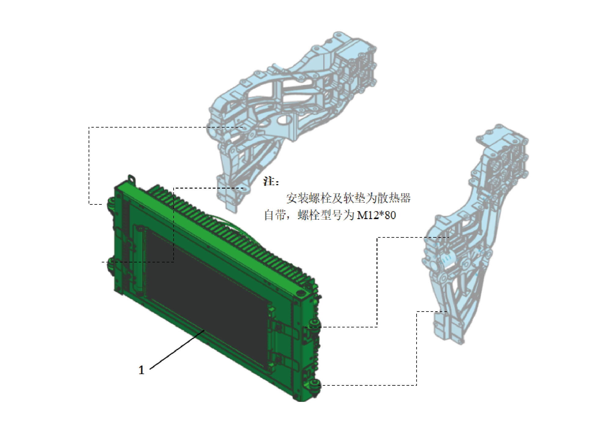
1.
FRont end Module
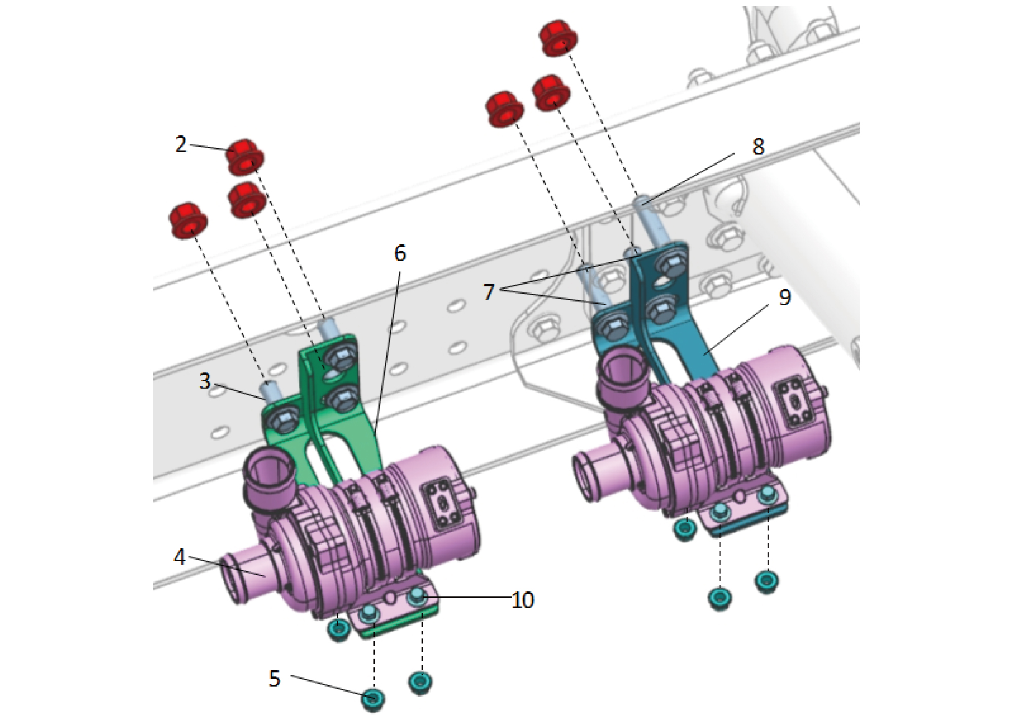
7.
2.
Hexagon Flange Lock Nut_all Metal
Hexagon Flange Bolt
3.
Hexagon Flange Bolt
8.
Hexagon Flange Bolt
4.
Electronic Water Pump
9.
Water Pump Fixing Bracket(Back)
5.
10.
Hexagon Flange Lock Nut_all Metal
Hexagon Flange Bolt
6.
Water Pump Fixing Bracket(Front)
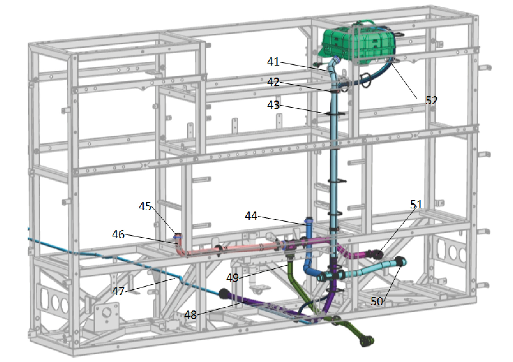
41.
47.
Water Refill Hose
Long Exhaust Pipe(l=5350)
42.
48.
Water Refill Hose 2
One-hole Fixing Clamp
43.
49.
PDU & Water outlet Hose of the Air Pump
Cable Ties 1
44.
50.
Water Inlet Hose of the Air Pump
Pdu Water Outlet Hose
45.
51.
Hose Hoop-type b and Type c
Water Outlet Hose of the Air Pump
46.
52.
Pdu Water Inlet Hose
Front end Module Outlet Nylon Pipe
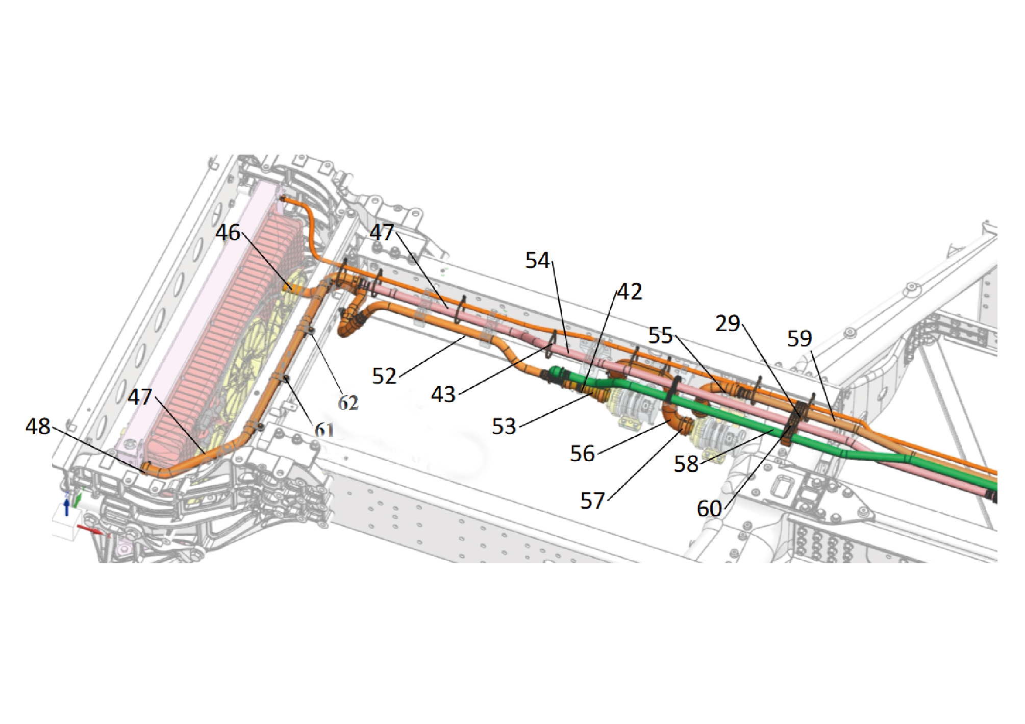
55.
29.
Three-hole Fixing Clamp
Rear Water Pmp Otlet Hse
42.
56.
Hose Btween Pmps
One-hole Fixing Clamp
57.
43.
Hose Hop-type b and Tpe c
Cable Ties 1
46.
Pdu Water Inlet Hose
58.
Hydrating nylon tube
47.
59.
Long Exhaust Pipe(l=5350)
Water Pump Out Nylon Pipe
48.
60.
Hexagon Flange Bolt
Water Refill Hose 2
52.
61.
Front end Module Outlet Nylon Pipe
Hose Clamp 1
53.
Front Pump - Water Inlet Hose
62.
Hexagon Flange Bolt
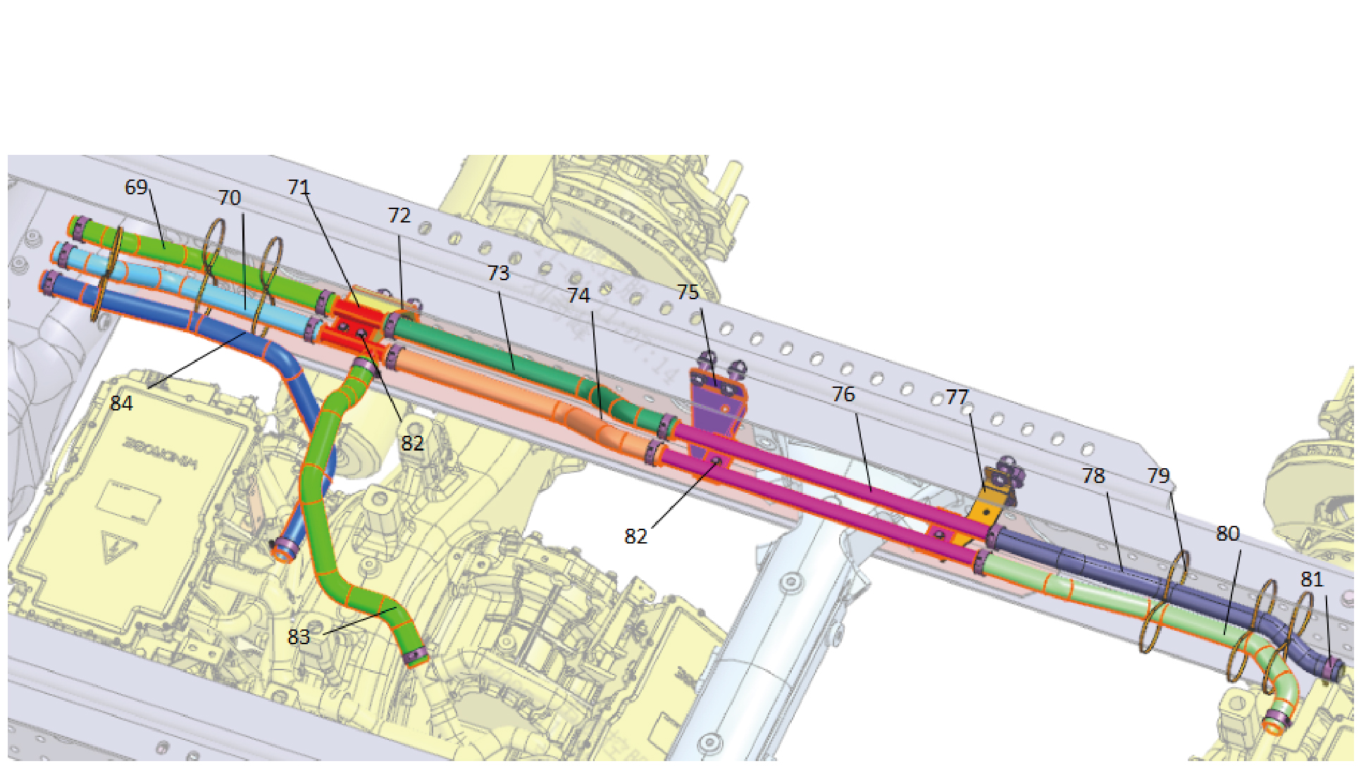
77.
69.
Rear Axle Water Inlet Hose 1
High-Voltage Harness Fixing Bracket Assembly
70.
78.
Rear Axle Water Inlet Hose 3
Middle and Rear Axle Water Outlet Hose 1
71.
79.
Middle and Rear Axle Combination Hose
Uble Hole Nylon Cable Tie(GTB-370ST)
72.
80.
Combined Hard Pipe Fixing Bracket
Middle and Rear Axle Water Outlet Hose 3
73.
Rear Axle Water Inlet Hose 2
81.
Hose Hop-type b and Tpe c
74.
82.
Hexagon Flange Bolt
Middle and Rear Axle Water Outlet Hose 2
75.
83.
Front of the Middle and Rear Axle Combined Hard Pipe
Middle and Rear Axle Water Outlet Hose
Fixing Bracket
76.
84.
M1 Water Inlet Hose 1
Middle and Rear Axle Combination Hose 2
Three-Motor GLB Status
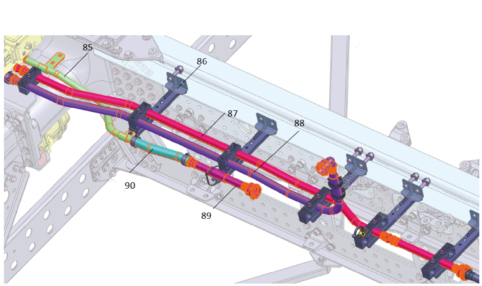
85.
88.
GLB Three-Motor Front Axle Water Inlet Steel Pipe
GLB Three-Motor Rear Axle Water Ingress - Nylon
Tube
86.
89.
GLB Three-Motor Dedicated Water Pipe Bracket 1
GLB Three-Motor Front Axle Water Ingress - Nylon
Tube
87.
90.
GLB Three-Motor Main Return Water - Nylon Tube
GLB Three-Motor Front Axle Water Ingress - Rubber
Hose
Four-Motor GLB Status
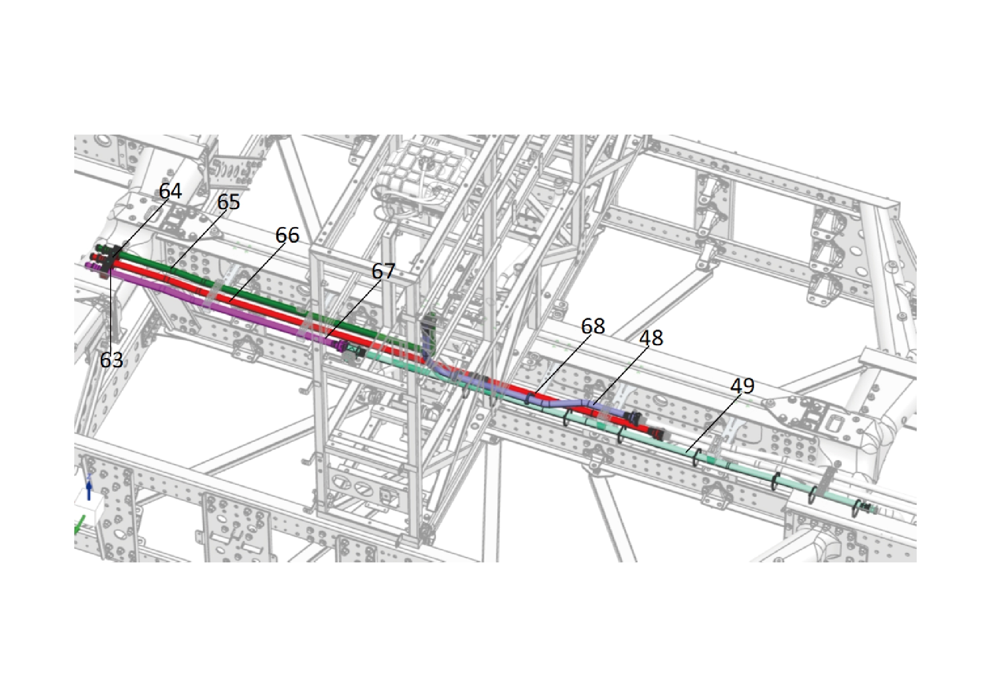
48.
65.
M1 Water Inlet Hose
Water Refill Hose 2
49.
66.
Front-end Module Water Inlet Nylon
Water Outlet Hose of PDU & Air Pump
63.
Hexagon Flange Bolt
67.
Water Inlet Nylon Tube 1 of M & MCU
64.
68.
Three-hole Fixing Clamp
Fixed Thread Rolling Strip(t120rh
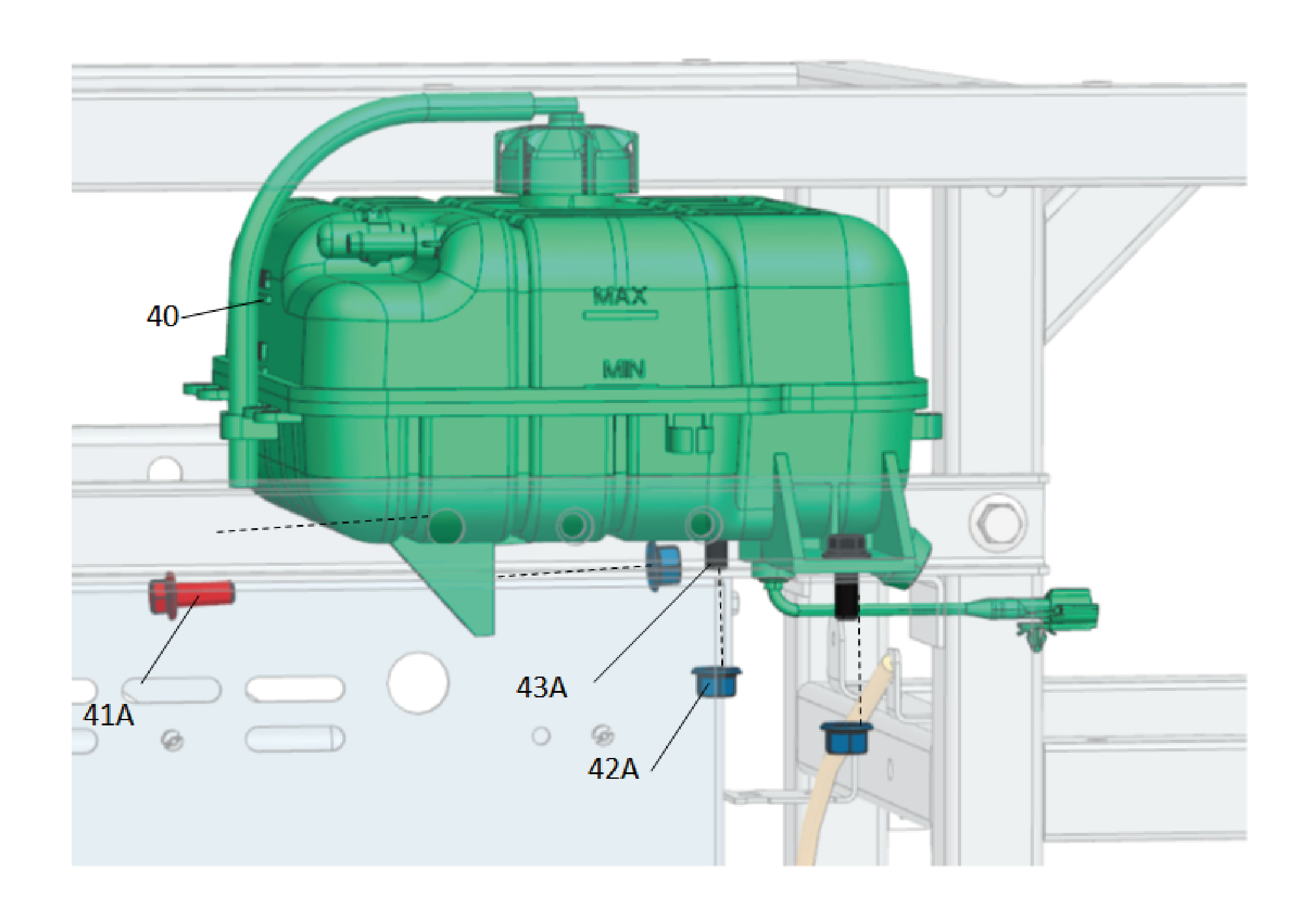
40.
Expansion Tank (Plastic)
42A.
Hexagon Flange Lock Nut_all Metal
41A.
Hexagon Flange Bolt
43A.
Hexagon Flange Bolt
4.4.3 Inspect
4.4.3.1 Inspection of Coolant
After the coolant temperature drops, check the coolant level in
the reservoir is between the MIN to MAX marks; If the coolant
is insufficient, the warning lamp on the instrument cluster will
be illuminated to remind you to add coolant.
If the coolant has suspended matter, sediment or
discoloration, replace it with new coolant immediately.
Regularly check the freezing point of the coolant to ensure
that it meets the requirements of the local environment and
replace it regularly.
4.4.4 The Working Principle of the System
4.4.4.1 System Working Principle
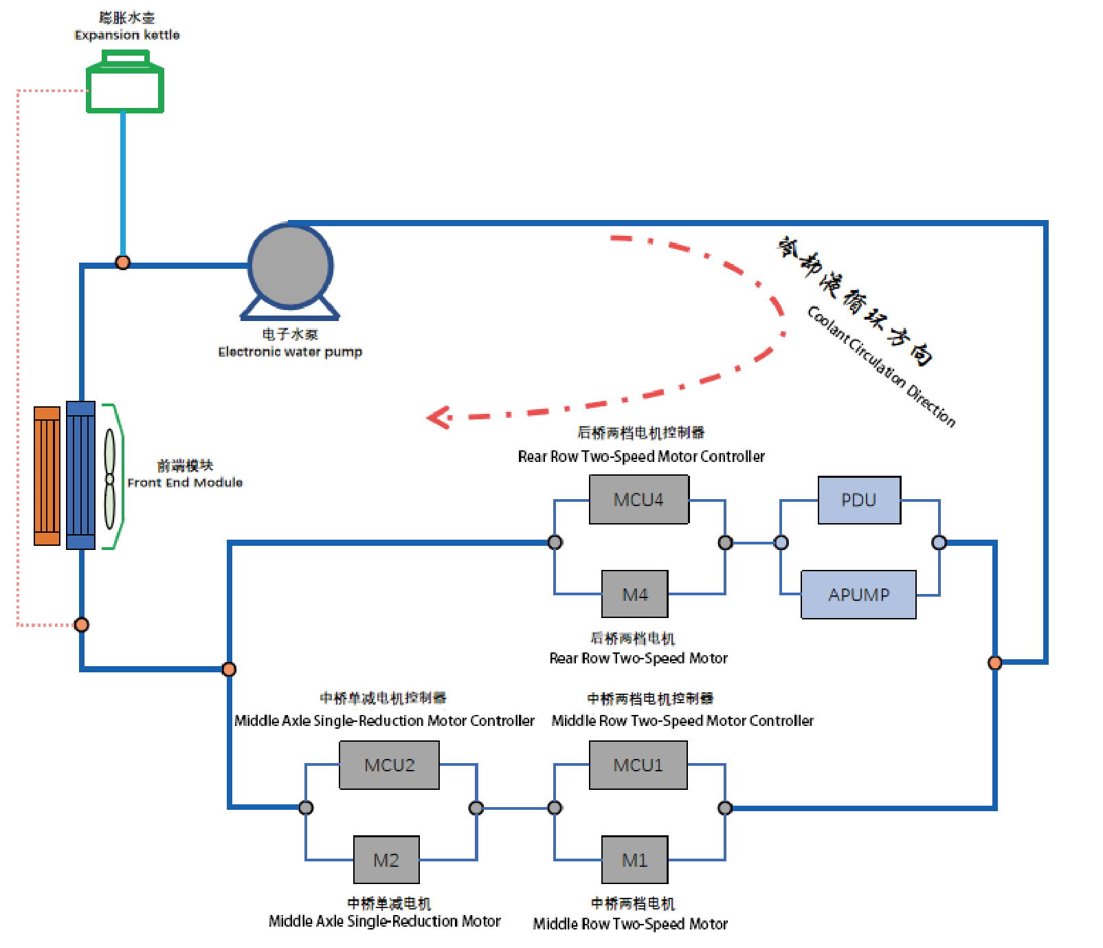
Three-motor Cooling Solution
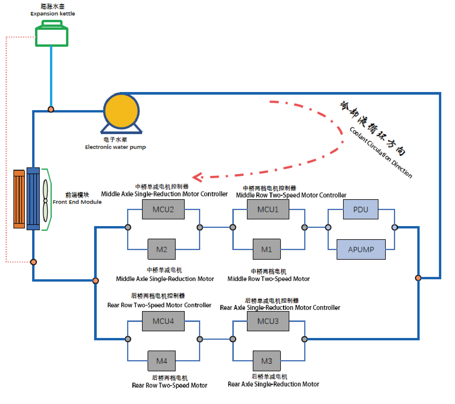
Four-motor Cooling Solution
4.4.5 Dismantling and Installation
4.4.5.1 Change of Power System Coolant
Removal Procedures
1
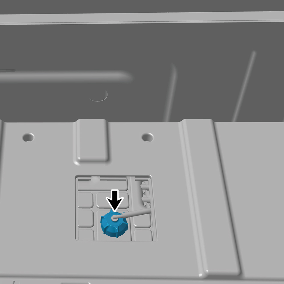
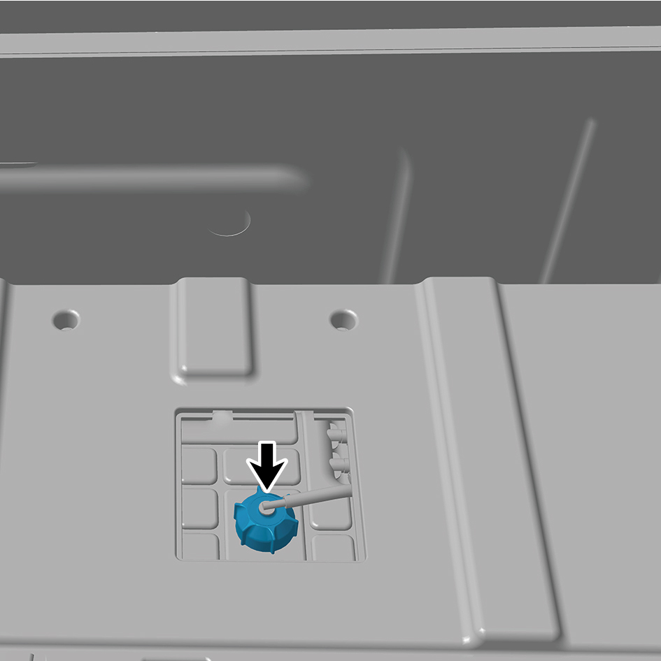
Remove the back integrated bracket upper cover plate
filler cap.
2
Detach the filler cap.
3
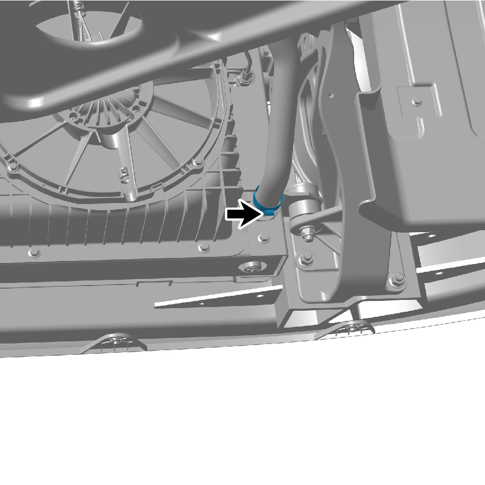
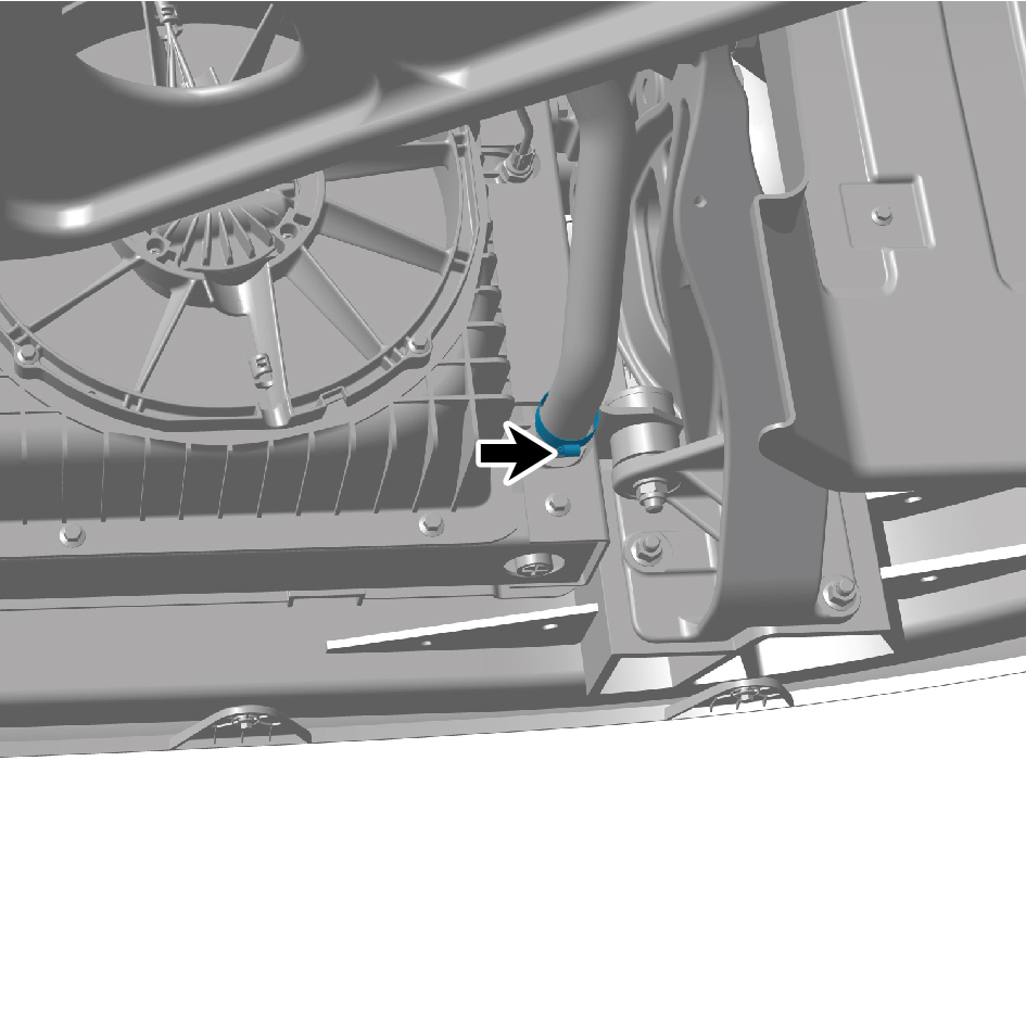
Disengage 1 clamp and disconnect the pipeline.
4
Drain coolant from the power system.
Installation Procedures
1
Connect the pipeline and attach 1 clamp.
2
Fill coolant in the power system.
caution
1. The coolant must meet the requirements of the
national standards, and the coolant of same model
cannot be mixed. It is recommended to use coolant
with a freezing point 14* F lower than the minimum
temperature in local area.
3
Install the filler cap.
4
Install the back integrated bracket upper cover plate filler
cap.
4.4.5.2 Change of Battery Thermal Management System Coolant
Management System Coolant
Removal Procedures
1
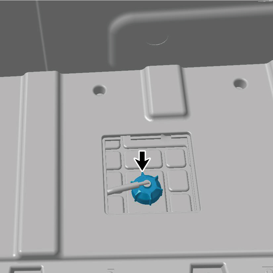
Remove the back integrated bracket upper cover plate
filler cap.
2
Detach the filler cap.
3
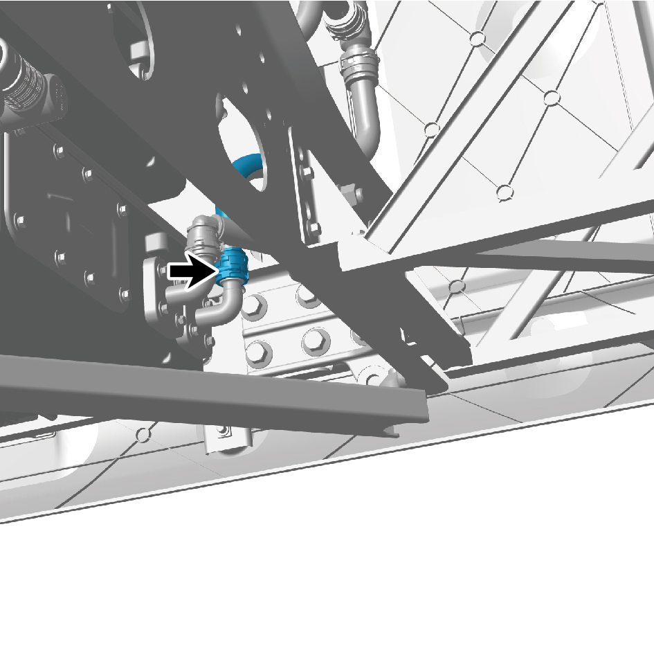
Disengage the pipeline.
4
Drain coolant from battery thermal management system.
Installation Procedures
1
Connect the pipeline.
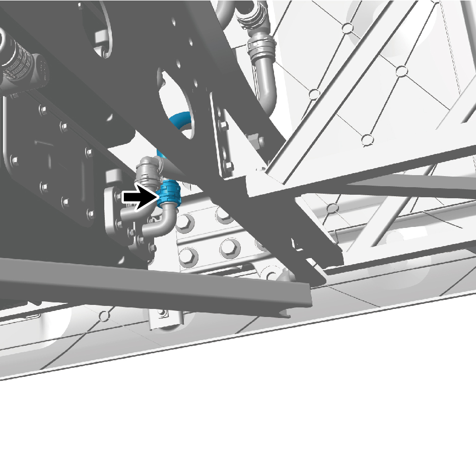
2
Fill coolant in the battery thermal management system.
caution
1. The coolant must meet the requirements of the
national standards, and the coolant of same model
cannot be mixed. It is recommended to use coolant
with a freezing point 14* F lower than the minimum
temperature in local area.
2. Add coolant to the auxiliary water tank until the
level is between the MIN and MAX marks. When
filling coolant, the air in the coolant cavity must be
discharged. For this reason, you should open the air
release valve (if any) on the radiator (water tank),
slowly add the coolant to prevent air blockage, and
wait for 2 to 3 minutes to completely discharge air.
The coolant should be filled into the bottom of the
water filling port or liquid level inspection port of the
radiator.
3
Install the filler cap.
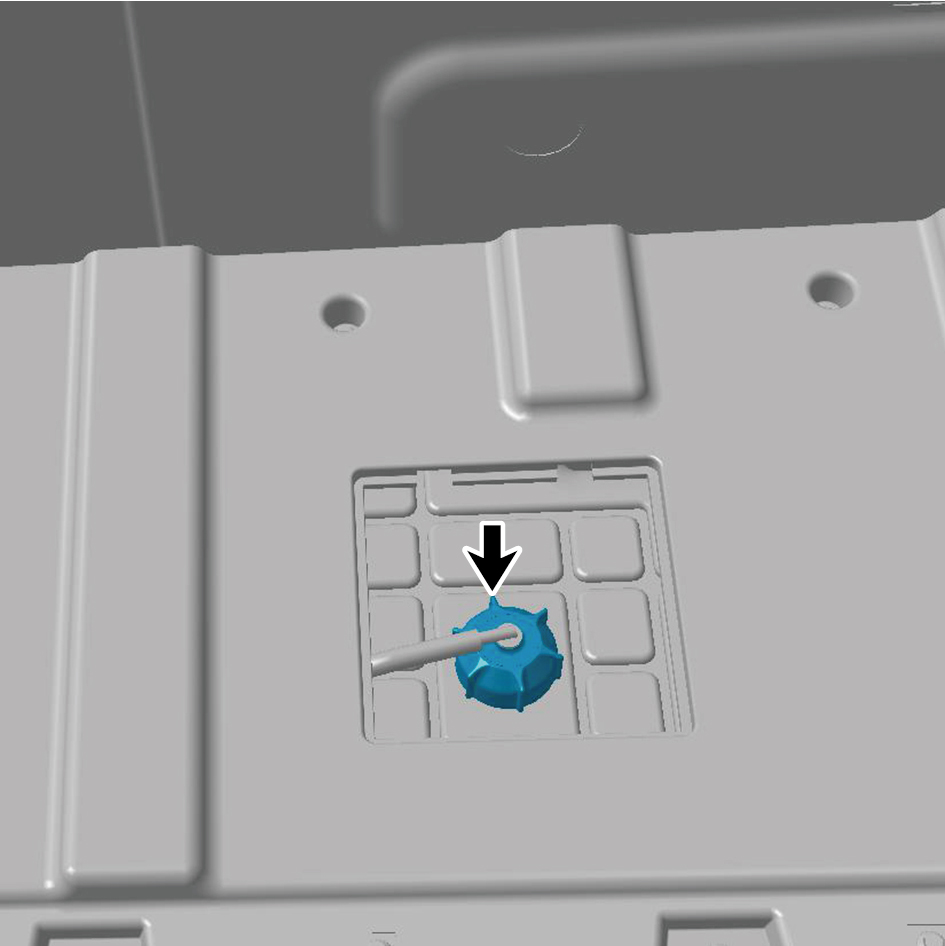
4
Install the back integrated bracket upper cover plate filler
cap.
4.4.5.3 Replacement of Front End Module
Removal Procedures
1
Open the door.
2
Open the front flip cover plate.
3
Disconnect the battery negative cable.
caution
The harness is firmly connected following the
principal of "insert until a click is heard for
confirmation".
4
Recycle A/C refrigerant.
5
Drain coolant from the power system.
6
Remove the engine compartment trim panel body.
7
Remove the through-type lamp.
8
Remove the front MMW radar shield.
9
Remove the forward MMW radar.
10
Remove the front MMW radar adapter bracket.
11
Remove the left cover plate of the corner radar.
12
Remove the right cover plate of the corner radar.
13
Remove the front bumper assembly.
14
Remove the electric horn assembly - low-pitch.
15
Remove the electric horn assembly - high-pitch.
16
Remove the sealing cross beam.
17
Remove the MMW radar bracket.
18
Remove the front lower protection assembly.
19
Remove the deflector assembly.
20
Remove the condenser.
21
Disconnect the 5 harness connectors of the front end
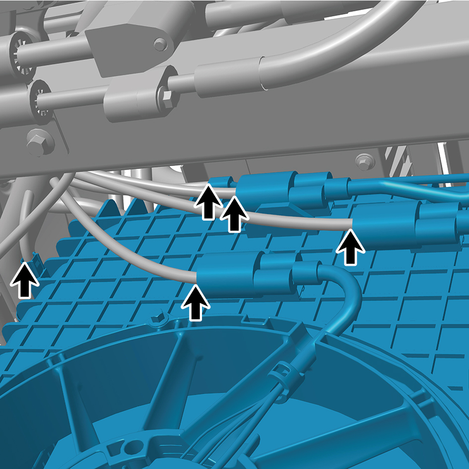
module.
22
Disconnect the 3 water pipes of the front end module.
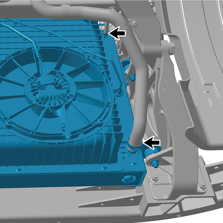
caution
Use a clean container to receive the discharged
coolant.
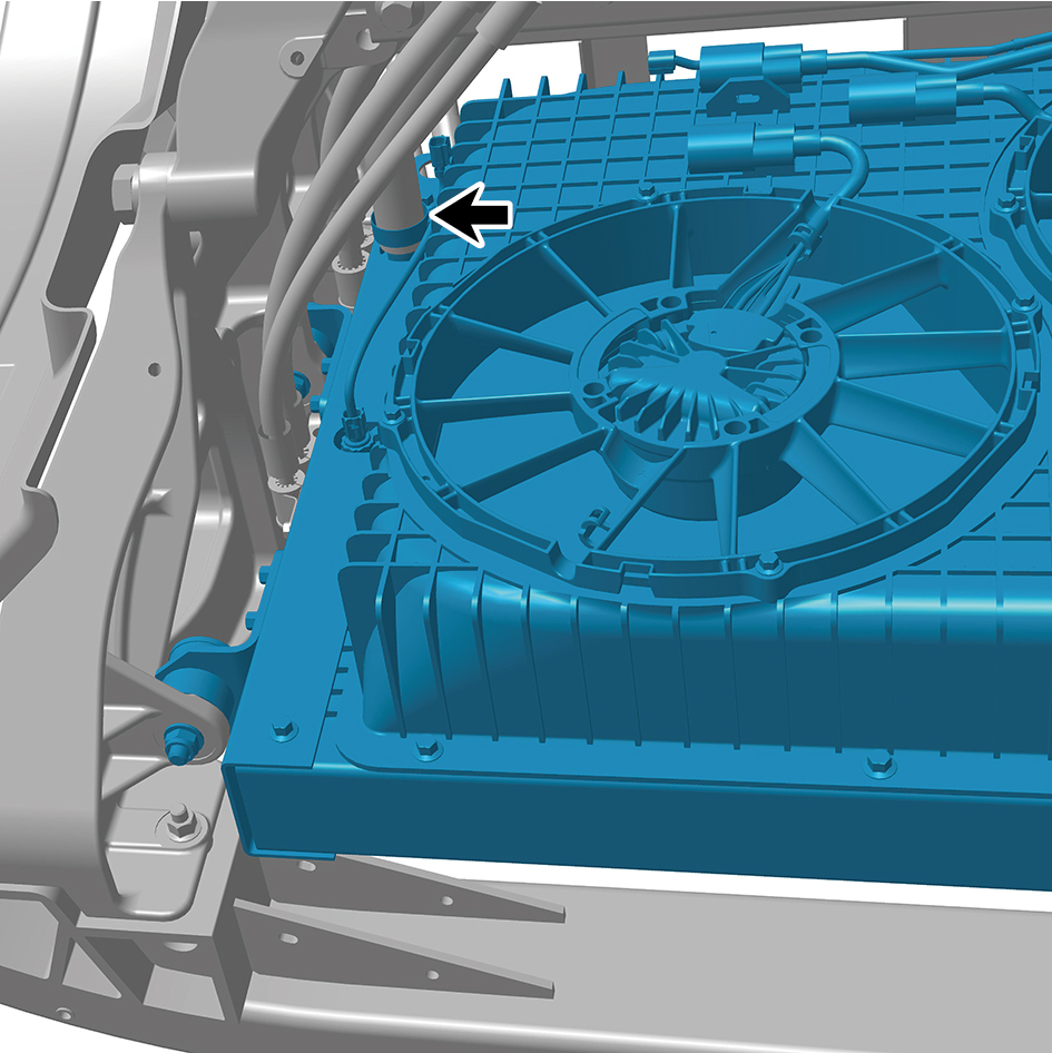
23
Remove the 5 clamp fixing bolts of the front end module.
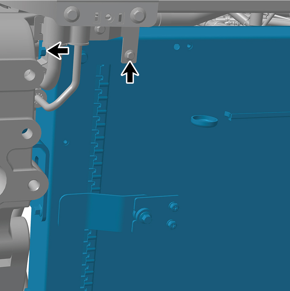
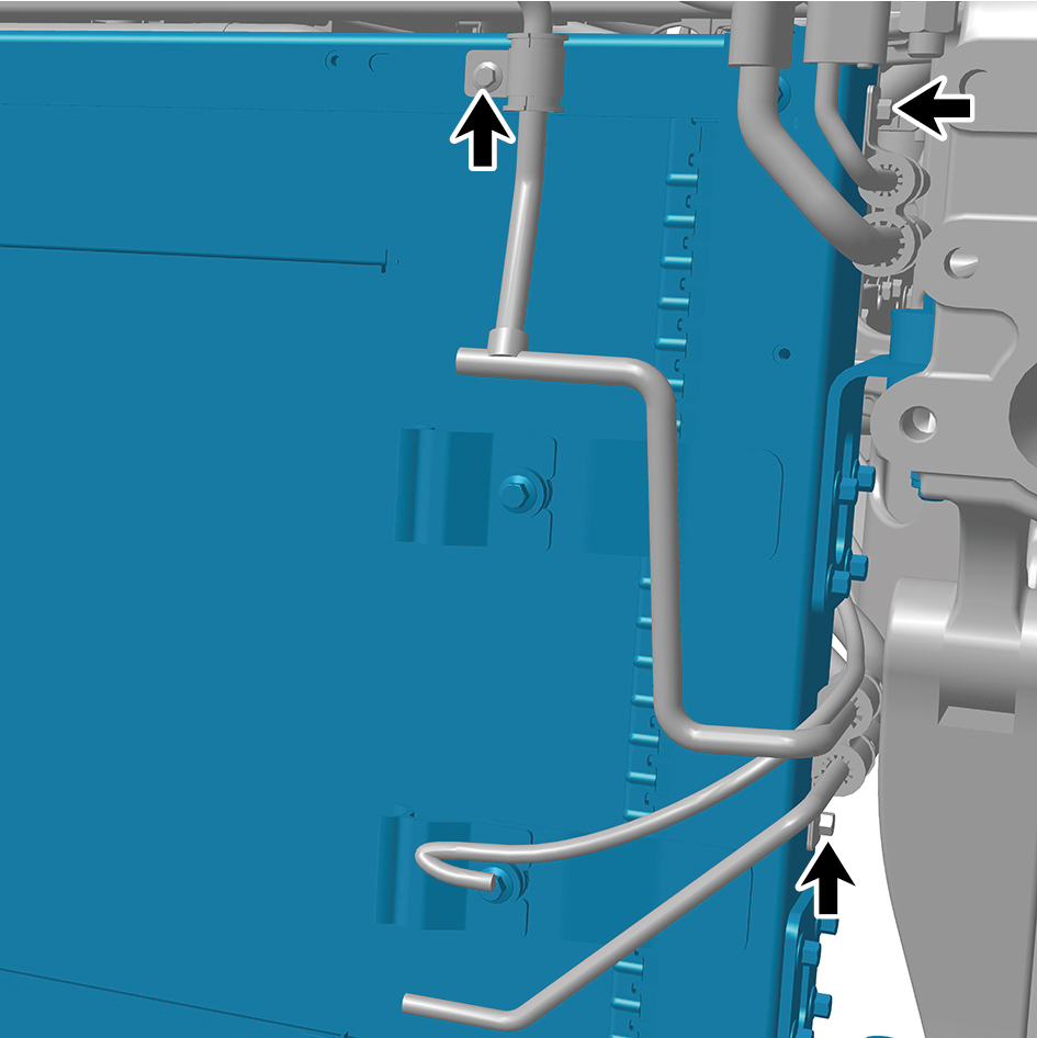
24
Remove the 4 fixing bolts of the front end module and
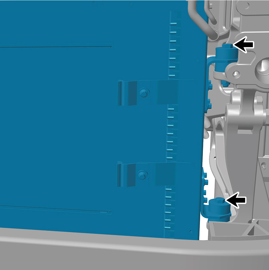
detach the front end module.
caution
Due to the heavy weight of the front end module, it
shall be removed with the help of an assistant.
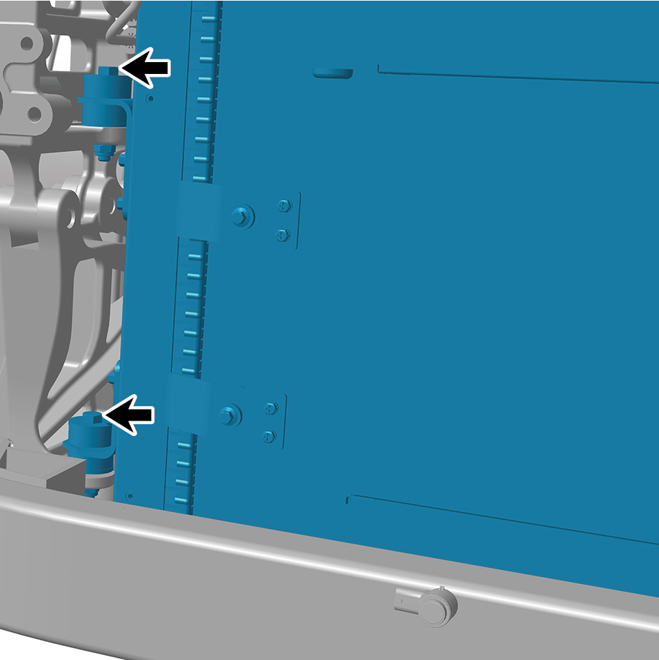
Installation Procedures
1
Move the front end module to the installation position.
caution
Due to the heavy weight of the front end module, it
shall be moved to the installation position with the
help of an assistant.
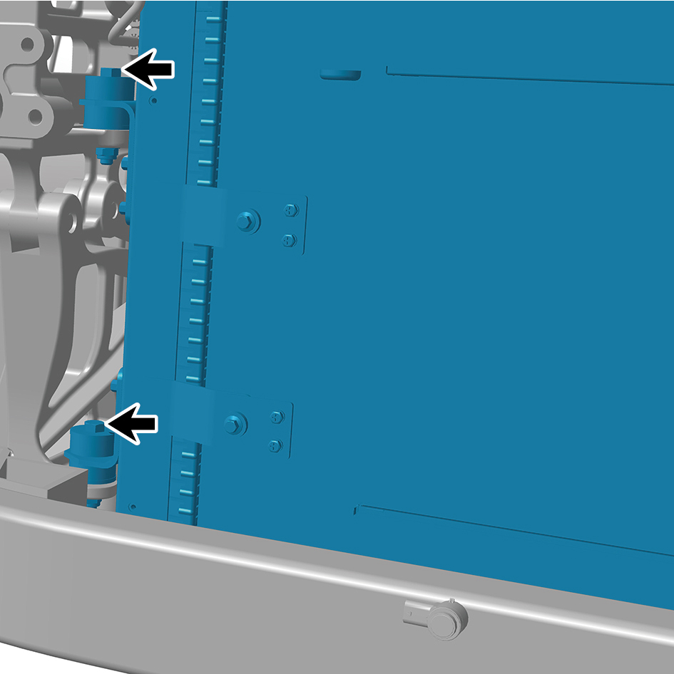
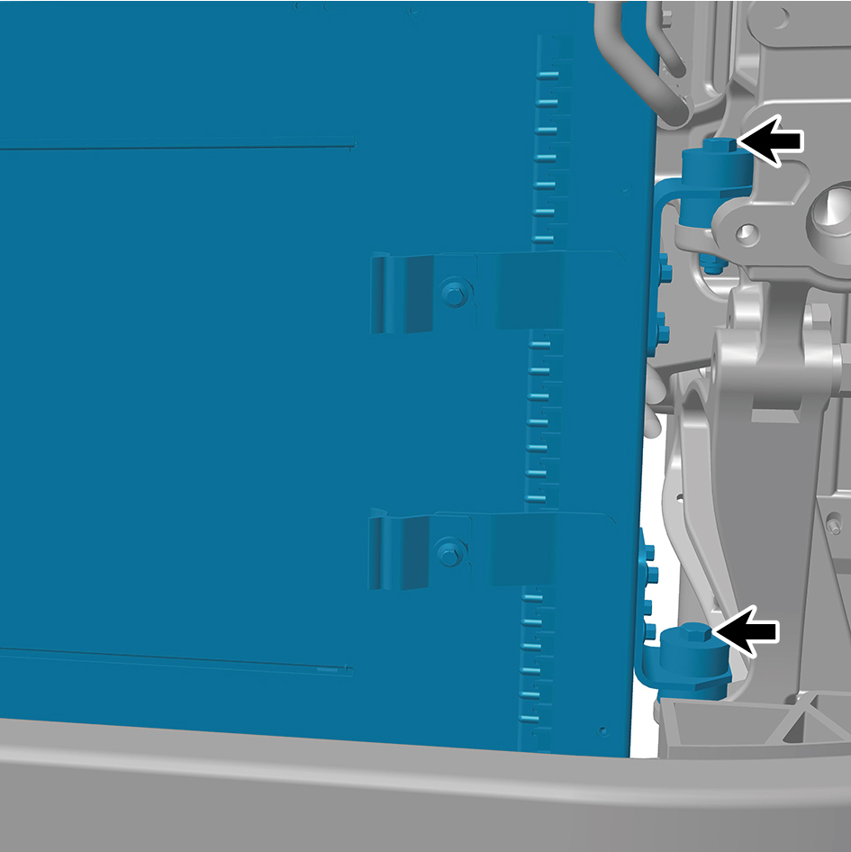
2
Install the 4 fixing bolts of the front end module.
Torque:(66 ft-lb +/-3.5 ft-lb) ft-lb
3
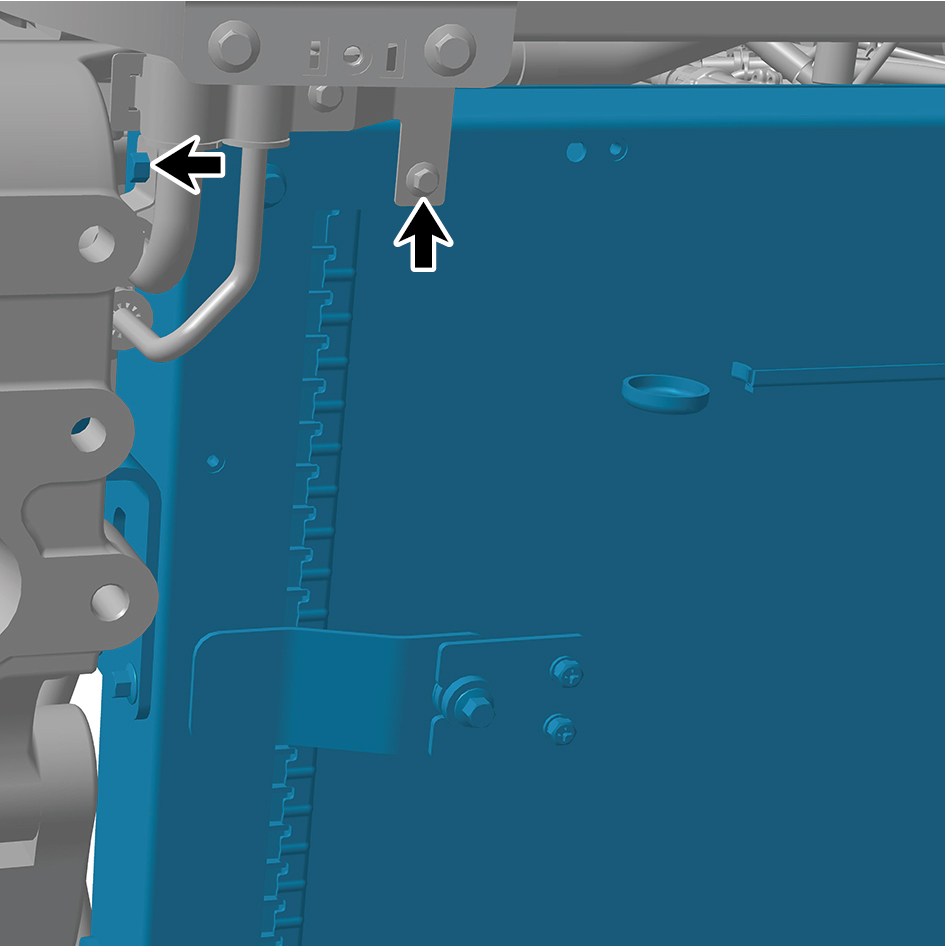
Install the 5 clamp fixing bolts of the front end module.
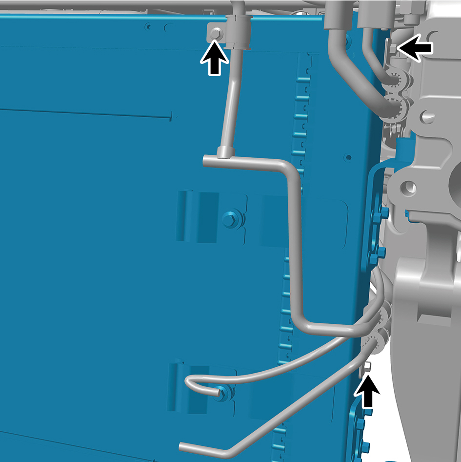
Torque: (18 ft-lb +/- 2 ft-lb) ft-lb
4
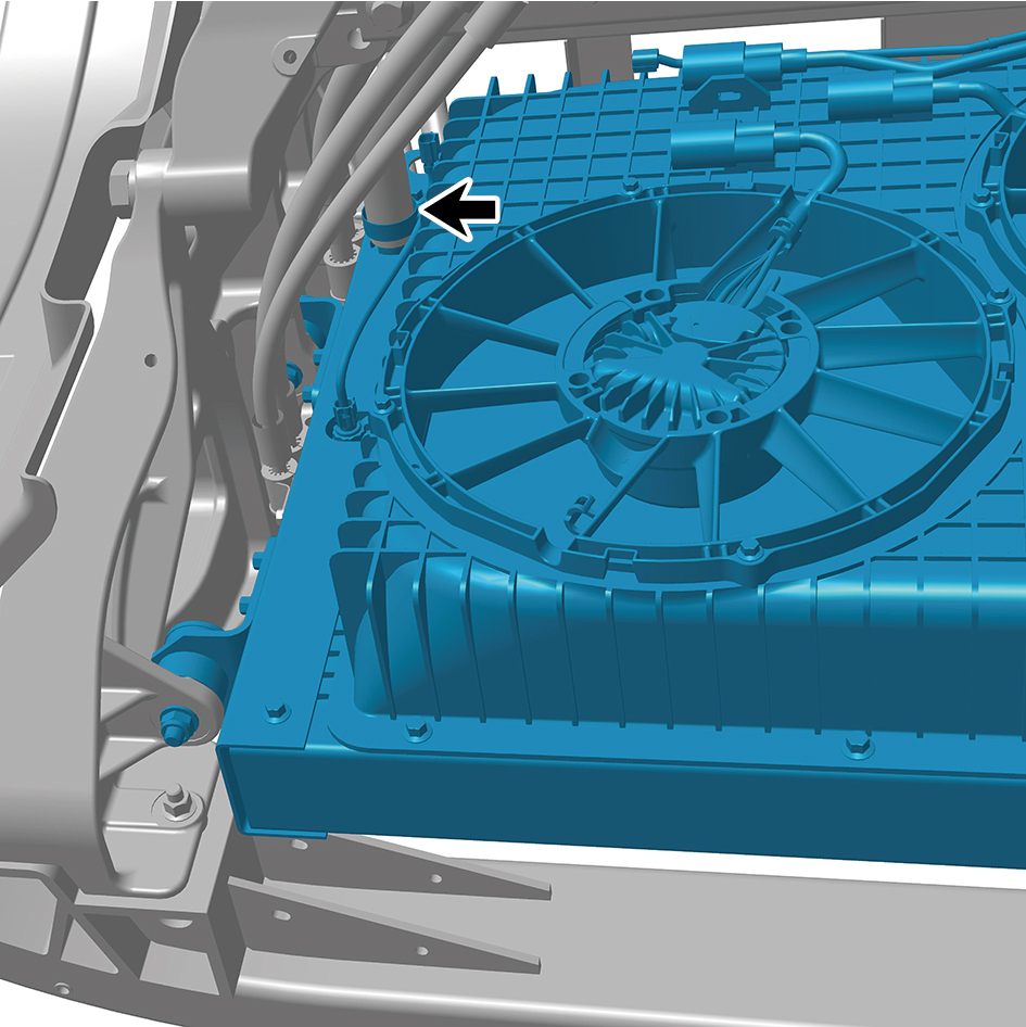
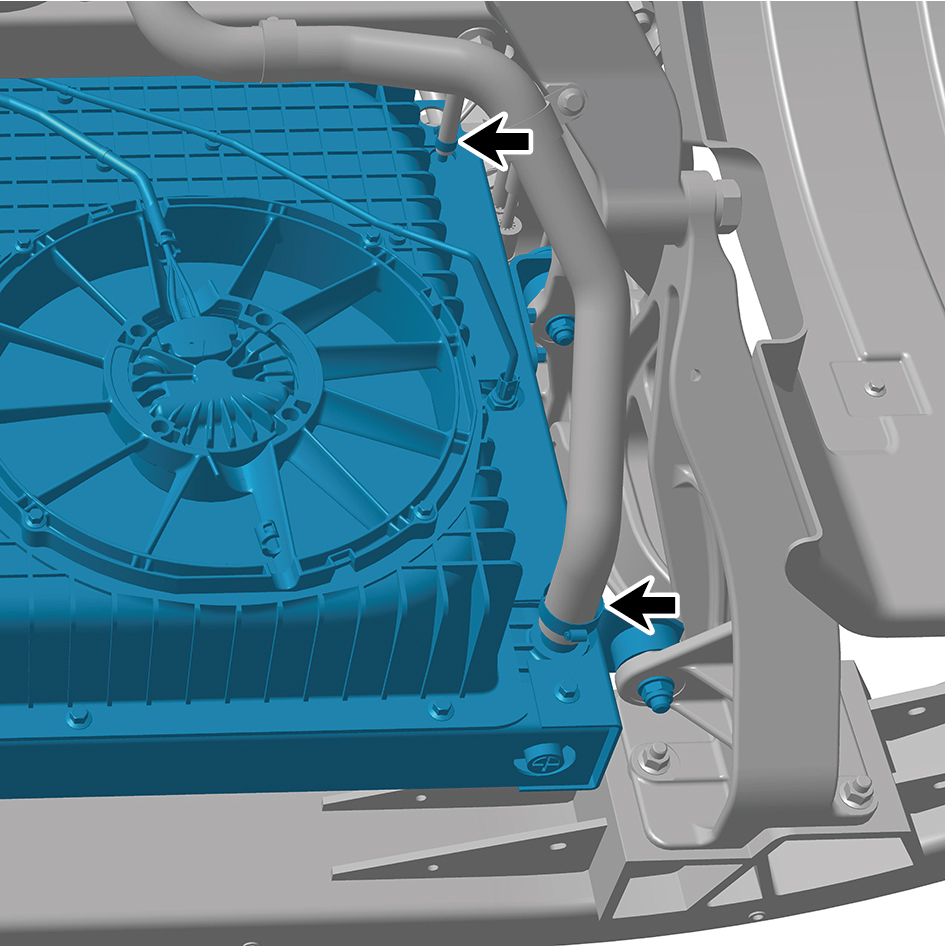
Connect the 3 water pipes of the front end module.
5
Connect the 5 harness connectors of the front end
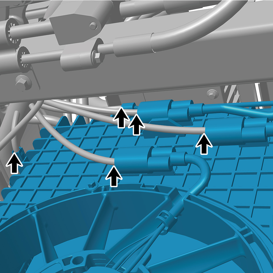
module.
caution
The harness is firmly connected following the
principal of "insert until a click is heard for
confirmation".
6
Install the condenser.
7
Install the deflector assembly.
8
Install the front lower protection assembly.
9
Install the MMW radar bracket.
10
Install the sealing cross beam.
11
Install the electric horn assembly - high-pitch.
12
Install the electric horn assembly - low-pitch.
13
Install the front bumper assembly.
14
Install the right cover plate of the corner radar.
15
Install the left cover plate of the corner radar.
16
Install the front MMW radar adapter bracket.
17
Install the forward MMW radar.
18
Install the front MMW radar shield.
19
Install the through-type lamp.
20
Install the engine compartment trim panel body.
21
Fill coolant in the power system.
22
Fill with A/C refrigerant.
23
Connect the battery negative cable.
24
Close the front flip cover plate.
25
Close the door.
4.4.5.4 Replacement of Electronic Water Pump
Removal Procedures
1
Open the door.
2
Open the front flip cover plate.
3
Disconnect the battery negative cable.
caution
The harness is firmly connected following the
principal of "insert until a click is heard for
confirmation".
4
Drain coolant from the power system.
5
Disconnect 1 harness connector of the electronic water
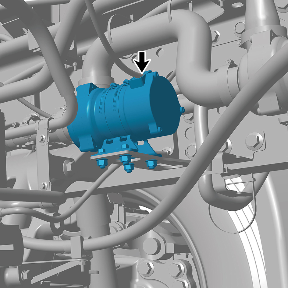
pump.
6
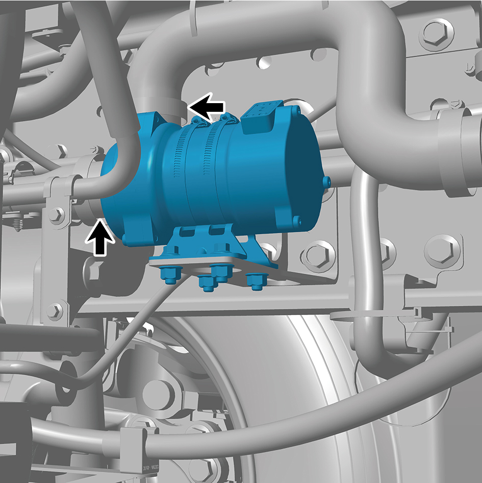
Disconnect the 2 water pipes of the electronic water
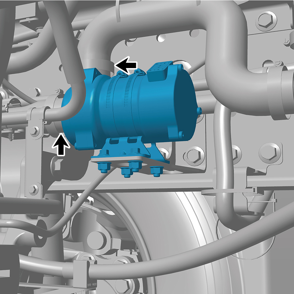
pump.
caution
Use a clean container to receive the discharged
coolant.
7
Remove the 4 fixing bolts and nuts of the electronic water
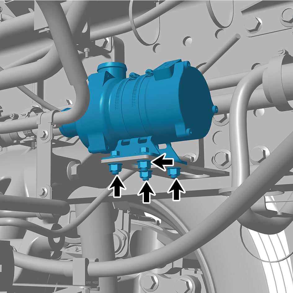
pump.
8
Remove the electronic water pump.
Installation Procedures
1
Move the electronic water pump to the installation
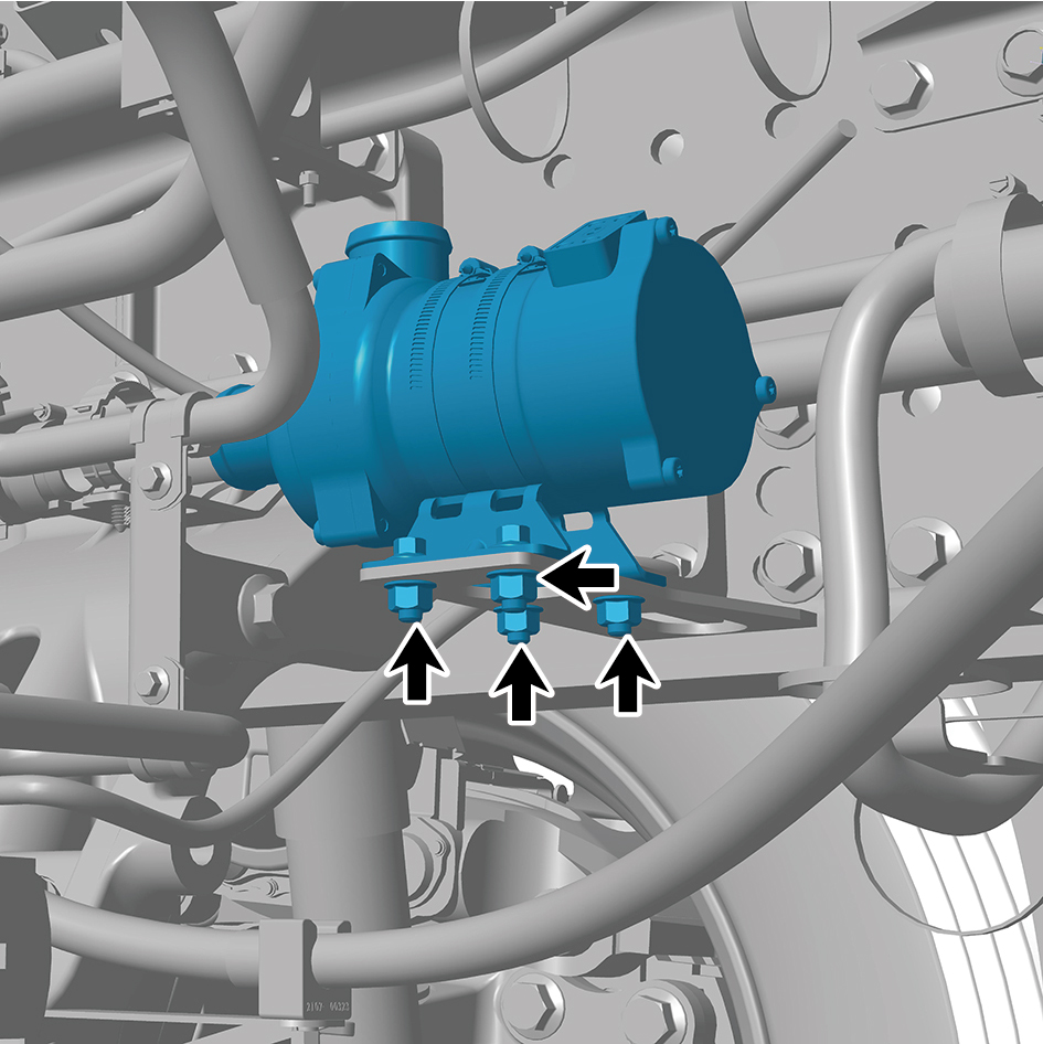
position.
2
Install the 4 fixing bolts and nuts of the electronic water
pump.
Torque:(18 ft-lb +/- 2 ft-lb) ft-lb
3
Connect the 2 water pipes of the electronic water pump.
4
Connect 1 harness connector of the electronic water
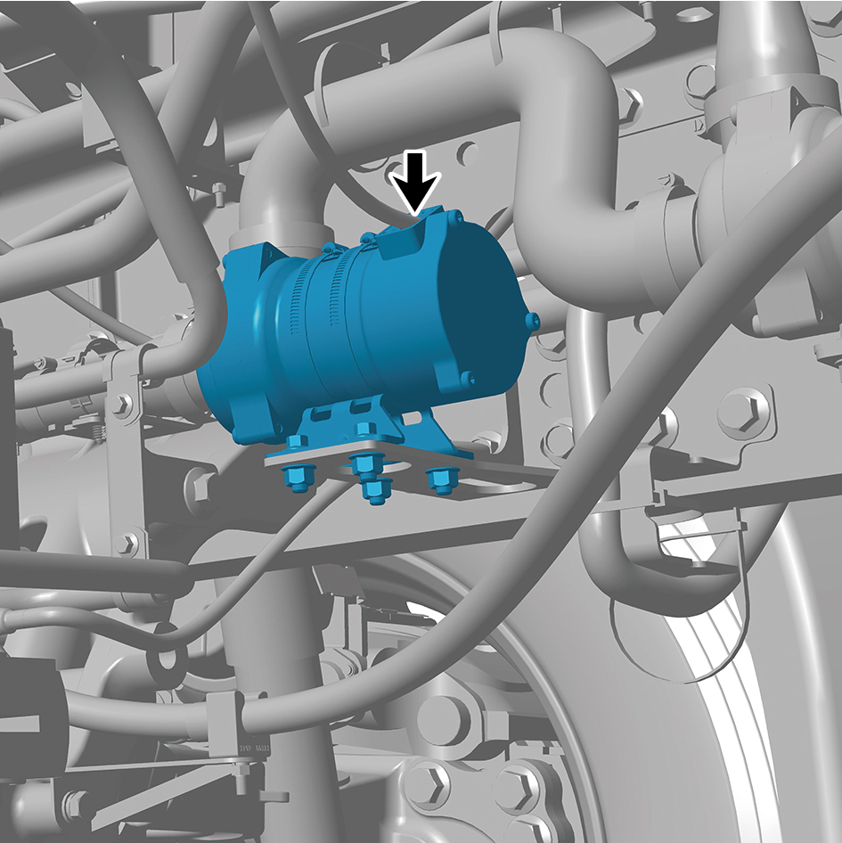
pump.
caution
The harness is firmly connected following the
principal of "insert until a click is heard for
confirmation".
5
Fill coolant in the power system.
6
Connect the battery negative cable.
7
Close the front flip cover plate.
8
Close the door.