← Back to Contents
4 New Energy Vehicle Components / 4.6 Multi-in-One Power Distribution Device | PDF pages 305-363
4.6 Multi-in-One Power Distribution Device
4.6 Multi-in-One Power Distribution Device
4.6 Multi-in-One Power Distribution
Device
4.6.1 Specifications
4.6.1.1 Fastener Specifications
Range Of Torque
Fastener Specifications
Specifications
Metric System(ft-lb)
Fixed bolts connecting the multi in one
power distribution assembly to the
(62 ft-lb +/- 6ft-lb) ft-lb
M12
integrated frame
The fixing nut connecting the multi in
one power distribution assembly and the
(62 ft-lb +/- 6ft-lb) ft-lb
M12
integrated frame
The fixing bolt of the grounding wire
harness on the multi in one power
(18 ft-lb +/- 2 ft-lb) ft-lb
M8
distribution assembly
The fixing bolt connecting the high-
voltage harness clamp to the high-
(22 ft-lb +/- 2 ft-lb) ft-lb
M10
voltage harness
4.6.1.2 Technical Parameters
DC/DC
Item
Parameter
Remark
Rated input voltage
750Vdc
/
Input voltage range
500~950Vdc
/
Maximum input current
14A
/
Auxiliary power input voltage
10~36V, communicable
16~32Vdc
Output rated voltage
27.5±0.3Vde (adjustable within 30Vdc)
It can respond to 30Vdc
Output rated current
218A
/
Peak output current
240A
6min
Rated output power
6000W
/
Peak output power
6600W
6min
Output efficiency
95.50%
/
Stabilized voltage precision
±1%
/
Stabilized current precision
±1%
/
Power regulation
±1%
/
Load regulation
±2%
/
Temperature coefficient
±0.02%/℃
/
Item
Parameter
Remark
Bandwidth limited to 20MHz,
10uF electrolytic capacitor and
Output ripple and noise
≤300mVp-p
0.1uF film capacitor connected
in parallel at the test end; 25℃
Output rise time
<500ms
/
On/off overshoot amplitude
≤±5%
/
On/off output delay
≤1s
/
Dynamic response overshoot
▲V: ≤+5%
/
Dynamic response recovery time
30%~80%~30% load change
≤5ms
Output current limiting characteristic
Constant current 240A
/
4.6.2 Decomposition Diagram
4.6.2.1 Decomposition Diagram
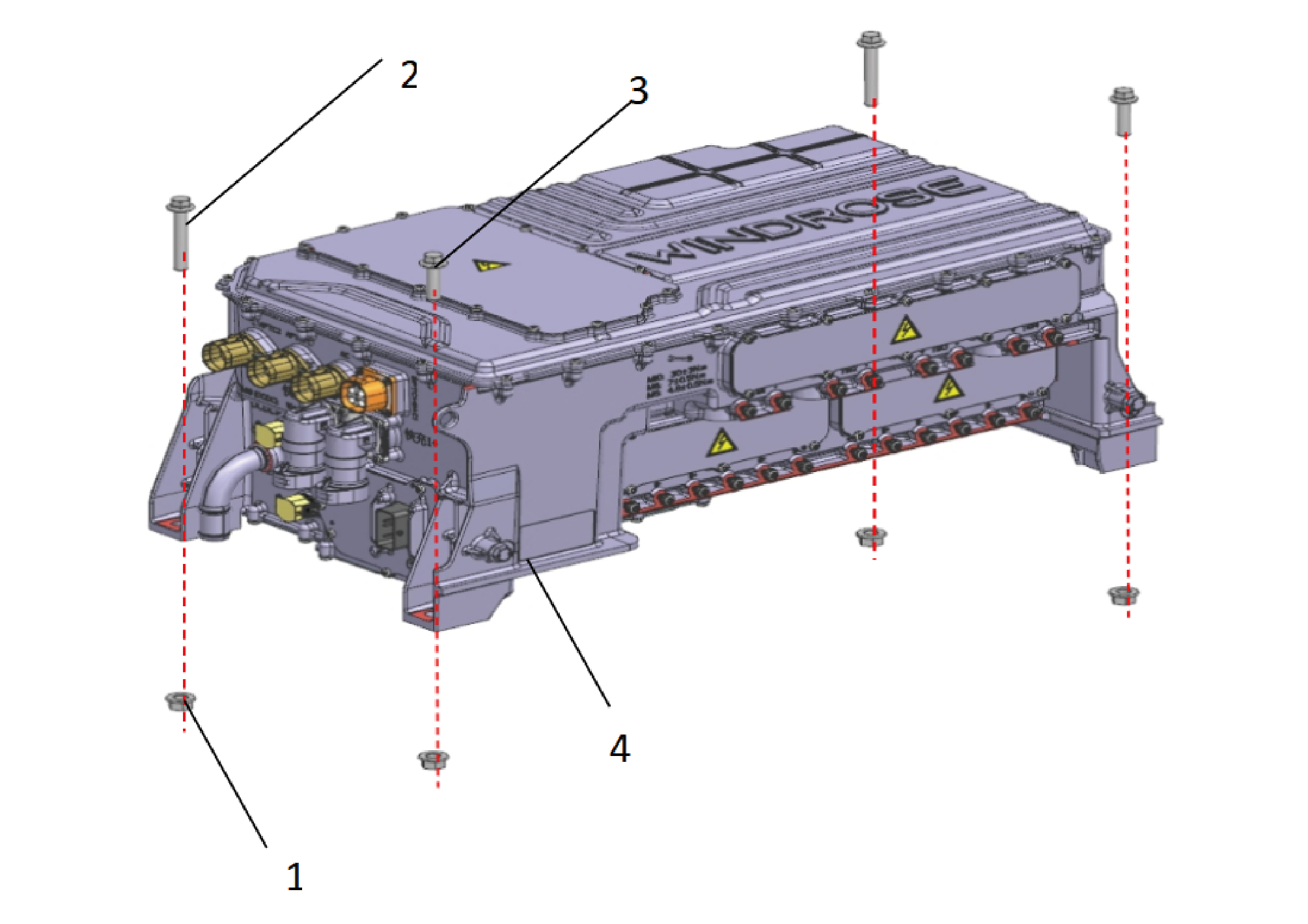
1.
Hexagon Flange Nut
3.
Hexagon Flange Bolt
2.
Hexagon Flange Bolt
4.
Auxiliary Drive All-in-One Assy
4.6.3 System Schematic Diagram
4.6.3.1 Electrical Schematic Diagram
4.6.4 Diagnostic Information and Steps
4.6.4.1 Diagnosis Description
Before diagnosing faults in multi in one power distribution equipment, Understanding and familiarizing oneself with the working
principle of multi in one power distribution equipment before starting system diagnosis can help determine the correct fault
diagnosis steps in the event of a fault, and more importantly, it can help determine whether the situation described by the
customer belongs to normal operation. Any fault diagnosis of multi in one power distribution equipment should start with routine
inspection, guiding maintenance personnel to take the next logical step for fault diagnosis. Understanding and correctly using the
diagnostic process can shorten the diagnosis time and avoid misjudgment of faulty parts.
4.6.4.2 Routine Inspection
• Check the after-sales installation devices that may affect the operation of the multi in one power distribution system to ensure
that these devices do not affect the operation of the multi in one power distribution system.
• Inspect system components that are easily accessible or visible to make sure they are not visibly damaged or have conditions
that could cause failure.
4.6.4.3 DTC Confirmation
1.Connect the diagnostic instrument to the diagnostic interface, read and record the DTC, and then clear the DTC.
2. Restart the vehicle.
3. Read the fault code of the control system again to confirm whether the system has a fault code output.
– Yes:Diagnose based on the output fault code.
– No:Perform intermittent fault checks, refer to Inspection Of Intermittent Fault
4.6.4.4 List Of Diagnostic Trouble Codes (DTCs)
DCDC1
Fault Description
Exclusion Method
Fault Code
The auxiliary power supply overvoltage
P1D0C00
Secondary power supply undervoltage
P1D0D00
Refer to DCDC1 Power Fault
Low pressure KL30
P1D0E00
Low pressure KL30
P1D0F00
Communication exception
P1D0B00
Refer to DCDC1 Communication Fault
Hardware overvoltage
P1D0500
P1D0600
Hardware overflows
P1D0700
KB fault
Refer to DCDC1 Internal Fault
P1D0800
Threshold fault
Short circuit protection
P1D0900
Refer to DCDC1 Overheating Fault
P1D0A00
The DCDC is overheated
The DCDC output overvoltage
P1D0200
Refer to DCDC1 Low-voltage Charging
The DCDC output undervoltage
P1D0300
System Fault
The DCDC output overflows
P1D0400
The input voltage of the DCDC is too
P1D0000
Refer to DCDC1 High Voltage Circuit
high
Fault
DCDC input undervoltage
P1D0100
DCDC2
Fault Description
Exclusion Method
Fault Code
The auxiliary power supply overvoltage
P1E0C00
Secondary power supply undervoltage
P1E0D00
Refer to DCDC2 Power Fault
Low pressure KL30
P1E0E00
Low pressure KL30
P1E0F00
Communication exception
P1E0B00
Refer to DCDC2 Communication Fault
Hardware overvoltage
P1E0500
P1E0600
Hardware overflows
P1E0700
KB fault
Refer to Internal Fault Of DCDC2
P1E0800
Threshold fault
Short circuit protection
P1E0900
Refer to DCDC2 Overheating Fault
P1E0A00
The DCDC is overheated
The DCDC output overvoltage
P1E0200
Refer to DCDC2 Low-voltage Power
The DCDC output undervoltage
P1E0300
Supply Sstem Fault
The DCDC output overflows
P1E0400
The input voltage of the DCDC is too
P1E0000
Refer to DCDC2 High Voltage Circuit
high
Fault
DCDC input undervoltage
P1E0100
PDU
Fault Description
Exclusion Method
Fault Code
KL30 voltage is too low when the main
P260700
drive circuit is powered on
The main contactor of the main drive
P260811
circuit is closed abnormally
KL30 is too low when the auxiliary drive
P260F00
circuit is powered on
Refer to PDU Power Fault
Auxiliary drive circuit main contactor
P261011
closing abnormal fault
Battery voltage is out of controller range
P261D00
fault
KL30 undervoltage fault
P261F11
KL30 overvoltage fault
P262011
P262211
Intranet BusOff Fault
P262311
Intranet DCDC communication alarm
Refer to PDU Communication Fault
P262411
Intranet TM1 communication alarm
P262511
Intranet TM2 communication alarm
Main contactor adhesion fault in main
P260000
drive circuit
Refer to Internal Fault Of PDU
Reverse voltage difference fault when
P260100
the main drive circuit is powered on
Fault Description
Exclusion Method
Fault Code
Main drive circuit power-on pre-charge
P260200
timeout fault
The rear end of the main drive circuit is
P260300
completely short-circuited.
Incomplete short circuit fault at the rear
P260400
end of the main drive circuit
Incomplete short circuit fault at the rear
P260500
secondary of the main drive circuit
Main drive circuit with speed power-on
P260600
fault
Auxiliary drive circuit main contactor
P260900
adhesion fault
Auxiliary drive circuit power-on reverse
P260A00
voltage difference fault
Auxiliary drive circuit power-on pre-
P260B00
charge timeout fault
The rear end of the auxiliary drive circuit
P260C00
is completely short-circuited
Incomplete short circuit fault at the rear
P260D00
end of the auxiliary drive circuit
Secondary incomplete short circuit fault
P260E00
at the rear end of the auxiliary drive
circuit
P261100
PTC1 contactor adhesion fault
P261200
PTC2 contactor adhesion fault
P261300
TOP1 contactor adhesion failure
P261400
TOP2 contactor adhesion failure
P261500
FAST1 contactor adhesion fault
P261600
FAST2 contactor adhesion fault
PTC1 closing abnormal fault
P261711
PTC2 closing abnormal fault
P261811
TOP1 closing abnormal fault
P261911
TOP2 closing abnormal fault
P261A11
FAST1 closing abnormality fault
P261B11
FAST2 closing abnormality fault
P261C11
Main negative contactor disconnect/
P261E00
battery feed
Compilation failure
P262100
APU
Fault Description
Exclusion Method
Fault Code
missing CDCU
U015687
U019887
VCAN bus-off
Refer to APU Communication Fault
U012287
Lost Communication with VDC
U008D88
PCAN3 BusOff
P1C0000
EPS hardware overcurrent fault
EPS drive upper axle failure
P1C0100
P1C0200
EPS drive lower axle failure
EPS drive undervoltage fault
P1C0300
EPS hardware overvoltage fault
P1C0400
EPS bus overvoltage fault
P1C0500
EPS bus undervoltage fault
P1C0600
P1C0700
EPS resolver failure
EPS phase failure
P1C0800
EPS AC zero drift is too large
P1C0900
P1C0A00
EPS Hall disconnection
EPS three-phase current verification
P1C0B00
error
EPSKL30 low voltage power supply
P1C0C00
undervoltage
EPSKL30 low voltage power supply
P1C0D00
overvoltage
Refer to APU Reports EHPS Related
EPS module over temperature fault
P1C0E00
Fault
EPS motor over temperature fault
P1C0F00
EPS motor overspeed failure
P1C1000
EPS speed deviation is too large
P1C1100
EPS active discharge timeout
P1C1200
EPS parameter tuning failed
P1C1300
EPS jam alarm
P1C1410
EPS bus voltage overvoltage drop
P1C1510
power
EPS bus voltage undervoltage alarm
P1C1610
EPS motor temperature sensor is
P1C1710
disconnected
EPS module over temperature alarm
P1C1810
EPS motor over temperature alarm
P1C1910
P1C1A10
EPS control overload alarm
P1C1B10
EPS motor overload alarm
EPS motor overspeed alarm
P1C1C10
Fault Description
Exclusion Method
Fault Code
EPS motor temperature sensor 1 is
P1C1D11
offline
EPS motor temperature sensor 2 is
P1C1E11
offline
EPSU phase current zero drift fault
P1C1F11
EPSV phase current zero drift fault
P1C2011
EPSW phase current zero drift fault
P1C2111
EPSU phase Hall wire disconnection
P1C2211
EPSV phase Hall wire disconnection
P1C2311
EPSW phase Hall disconnection
P1C2411
EPSCompilation failure
P1C2500
P1C2600
EPS EEPROM read and write failure
P1C2700
ACM hardware overcurrent fault
ACM driver upper axle failure
P1C2800
P1C2900
ACM drive lower axle fault
ACM driver undervoltage fault
P1C2A00
ACM hardware overvoltage fault
P1C2B00
ACM bus overvoltage fault
P1C2C00
ACM bus undervoltage fault
P1C2D00
P1C2E00
ACM resolver failure
ACM phase failure
P1C2F00
ACM AC zero drift is too large
P1C3000
P1C3100
ACM Hall disconnection
ACM three-phase current verification
P1C3200
error
Refer to APU Reports Air Compressor
ACM KL30 low voltage power supply
P1C3300
Related Fault
undervoltage
ACM KL30 Low Voltage Power Supply
P1C3400
Overvoltage
ACM module over temperature fault
P1C3500
ACM motor over temperature fault
P1C3600
ACM Motor Overspeed Fault
P1C3700
ACM speed deviation too large
P1C3800
ACM Active Discharge Timeout
P1C3900
ACM parameter tuning failed
P1C3A00
P1C3B10
ACM stall alarm
ACM bus voltage overvoltage drop
P1C3C10
power
ACM bus voltage undervoltage alarm
P1C3D10
Fault Description
Exclusion Method
Fault Code
ACM motor temperature sensor
P1C3E10
disconnected
ACM module over temperature alarm
P1C3F10
ACM motor over temperature alarm
P1C4010
P1C4110
ACM control overload alarm
P1C4210
ACM motor overload alarm
ACM Motor Overspeed Alarm
P1C4310
ACM motor temperature sensor 1 is
P1C4411
offline
ACM motor temperature sensor 2 is
P1C4511
offline
U phase current zero drift fault
P1C4611
V phase current zero drift fault
P1C4711
W phase current zero drift fault
P1C4811
U phase Hall wire disconnection
P1C4911
V phase Hall wire disconnection
P1C4A11
W phase Hall disconnection
P1C4B11
Compilation failure
P1C4C00
P1C4D00
EEPROM read and write failure
4.6.4.5 DCDC1 Power Fault
1.DTC Monitoring Logic
Description
DTC Trigger Conditions
Faulty Part
DTC Code
The auxiliary power
1. Main battery
The auxiliary power supply voltage is greater than 13V
P1D0C00
supply overvoltage
2. Low voltage
Secondary power
charging system
The auxiliary power supply voltage is less than 9V
P1D0D00
supply undervoltage
3. Wiring harness
4. Power
Low pressure KL30
The KL30 voltage is greater than 37V
P1D0E00
distribution unit
Low pressure KL30
The KL30 voltage is less than 9V
P1D0F00
2.Circuit Diagram
Smart Junction
Box - Chassis
E-axle rear
E-axle mid
axle vehicle
Air condition-
axle vehicle
Battery
VDC-1
low voltage
ing compres-
low voltage
port
sor
port
C25-1
C27-1
C93-97
C68-8
drive wake up the power supply E146
The PDU, TCU, middrive, and rear
C4-8
Wake-up call E146a
Wake-up call E146b
PDU-KL30 O408
Ground Z60
G04
High voltage interlock output H05
Power KL30 O408a
Power KL30 O408b
Wake up power E146
Ground Z60
Ground Z60
C34-B1
C34-L1
C34-L2
C34-E1
C34-M1
C34-M2
Power distribution unit
C34-A1
C34-E4
C34-E3
PCAN3-L PL03g
PCAN3-H PH03g
High voltage interlock in from left unit H06
PCAN3-H PH03
PCAN3-H PH03h
PCAN3-H PH03i
PCAN3-L PL03
PCAN3-L PL03i
PCAN3-L PL03h
C88-11
C88-8
C89-8
C94-28
C88-7
C89-7
C94-27
VDC-2
Left thermal management unit 1
Right thermal management unit 1
3. Diagnostic Steps
Step 1:DTC Confirmation. Refer to DTC Confirmation
Step 2:Routine Inspection. Refer to Routine Inspection
Step 3:Check if there are any other module power failure codes besides DCDC1?
Check the main battery. Refer to Inspection Of The Main Battery
– Yes:
Check the low-voltage charging system. Refer to DCDC1 Low-voltage Charging System Malfunction
Next step
– No:
Step 4:Check the power distribution unit power supply and grounding harness.
Step 5:Rewrite the configuration code of the power distribution unit, reload the software, and upgrade.
Step 6:Replace the power distribution unit. Refer to Replacement Of Multi In One Power Distribution Assembly
Step 7:Clear and confirm DTC.
4.6.4.6 DCDC1 Communication Fault
1.DTC Monitoring Logic
Description
DTC Trigger Conditions
Faulty Part
DTC Code
1.Wiring harness
Communication
30s The correct packet frame was not received
P1D0B00
2. Power
exception
distribution unit
2.Circuit Diagram
Smart Junction
Box - Chassis
E-axle rear
E-axle mid
axle vehicle
Air condition-
axle vehicle
Battery
VDC-1
low voltage
ing compres-
low voltage
port
sor
port
C25-1
C27-1
C93-97
C68-8
drive wake up the power supply E146
The PDU, TCU, middrive, and rear
C4-8
Wake-up call E146a
Wake-up call E146b
PDU-KL30 O408
Ground Z60
G04
High voltage interlock output H05
Power KL30 O408a
Power KL30 O408b
Wake up power E146
Ground Z60
Ground Z60
C34-B1
C34-L1
C34-L2
C34-E1
C34-M1
C34-M2
Power distribution unit
C34-A1
C34-E4
C34-E3
PCAN3-L PL03g
PCAN3-H PH03g
High voltage interlock in from left unit H06
PCAN3-H PH03
PCAN3-H PH03h
PCAN3-H PH03i
PCAN3-L PL03
PCAN3-L PL03i
PCAN3-L PL03h
C88-11
C88-8
C89-8
C94-28
C88-7
C89-7
C94-27
VDC-2
Left thermal management unit 1
Right thermal management unit 1
3. Diagnostic Steps
Step 1:DTC Confirmation. Refer to DTC Confirmation
Step 2:Routine Inspection. Refer to Routine Inspection
Step 3:Check the PCAN3 bus communication harness. Refer to Inspection of PCAN3 bus network integrity
Step 4:Rewrite the configuration code of the power distribution unit, reload the software, and upgrade.
Step 5:Replace the power distribution unit. Refer to Replacement Of Multi In One Power Distribution Assembly
Step 6:Clear and confirm DTC.
4.6.4.7 DCDC1 Internal Fault
1.DTC Monitoring Logic
Description
DTC Trigger Conditions
Faulty Part
DTC Code
Hardware overvoltage
Comparator equivalent voltage greater than 37V
P1D0500
Comparator equivalent current greater than 350A
P1D0600
Hardware overflows
1. Power
P1D0700
KB fault
The correct KB correction factor was not read
distribution unit
P1D0800
Threshold fault
The correct fault threshold was not read. Procedure
The output voltage is lower than 4V and the output
Short circuit protection
P1D0900
current is greater than 180A
2. Diagnostic Steps
Step 1:DTC Confirmation. Refer to DTC Confirmation
Step 2:Routine Inspection. Refer to Routine Inspection
Step 3:Rewrite the configuration code, reload the software, and upgrade the power distribution unit.
Step 4:Replace the power distribution unit. Refer to Replacement of Multi in One Power Distribution Assembly
Step 5:Clear and confirm DTC.
4.6.4.8 DCDC1 Overheating Fault
1.DTC Monitoring Logic
Description
DTC Trigger Conditions
Faulty Part
DTC Code
The primary temperature of DCDC is greater than
239℉. Or the secondary side temperature of DCDC is
1. Power
The DCDC is
P1D0A00
greater than 239℉; Or the ambient temperature is
distribution unit
overheated
greater than 239℉
2. Diagnostic Steps
Step 1:DTC Confirmation. Refer to DTC Confirmation
Step 2:Routine Inspection. Refer to Routine Inspection
Step 3:Move the vehicle to a normal temperature environment and let it sit for a while.
Step 4:Check the vehicle has any fault codes related to the thermal management system?
Prioritize troubleshooting related to thermal management systems.
– Yes:
Next step
– No:
Step 5:Rewrite the configuration code of the power distribution unit, reload the software, and upgrade.
Step 6:Replace the power distribution unit. Refer to Replacement Of Multi In One Power Distribution Assembly
Step 7:Clear and confirm DTC.
4.6.4.9 DCDC1 Low-voltage Charging System Fault
1.DTC Monitoring Logic
Description
DTC Trigger Conditions
Faulty Part
DTC Code
The DCDC output
The output voltage is greater than 32V
P1D0200
overvoltage
1. Main battery
2. Wiring harness
The DCDC output
The output voltage is lower than 18V
P1D0300
3. Power
undervoltage
distribution unit
The DCDC output
The output current is greater than 200A
P1D0400
overflows
2.Circuit Diagram
IBS-B+ O308
5A
Power 001
24V+ O308
Battery
BE12-1
C91-3
Intelligent Battery Sensor
BE02-1
C91-1
C91-2
LIN E251d
Ground Z20
12V+ O07
Shutter LIN E251
Active Grille
G17
5A
19
I7_C_B
19
I7_B_C
IIBS/AGSLIN cable E251
AGS-LIN E251c
12V+ O07
11
I_B_BU
11
I_BU_B
AGS-LIN E251c
BU05-1
C94-7
C92-1
IBS12V
Active Grille Shutter
VDC-2
power supply
3. Diagnostic Steps
Step 1:DTC Confirmation. Refer to DTC Confirmation
Step 2:Routine Inspection. Refer to Routine Inspection
Step 3:Check the main battery. Refer to Inspection Of The Main Battery
Step 4:Check the low-voltage charging circuit of the power distribution unit (integrated DCDC).
Step 5:Rewrite the configuration code of the power distribution unit, reload the software, and upgrade.
Step 6:Replace the power distribution unit. Refer to Replacement Of Multi In One Power Distribution Assembly
Step 7:Clear and confirm DTC.
4.6.4.10 DCDC1 High Voltage Circuit Fault
1.DTC Monitoring Logic
Description
DTC Trigger Conditions
Faulty Part
DTC Code
The input voltage of
1. High voltage
The input voltage is greater than 960V
P1D0000
the DCDC is too high
wiring harness
2. Power
DCDC input
The input voltage is lower than 480V
P1D0100
distribution unit
undervoltage
2. Diagnostic Steps
Step 1:DTC Confirmation. Refer to DTC Confirmation
Step 2:Routine Inspection. Refer to Routine Inspection
Step 3:Check the power distribution unit high-voltage harness.
Step 4:Check the internal insulation detection circuit of the power distribution unit.
Step 5:Rewrite the configuration code of the power distribution unit, reload the software, and upgrade.
Step 6:Replace the power distribution unit. Refer to Replacement Of Multi In One Power Distribution Assembly
Step 7:Clear and confirm DTC.
4.6.4.11 DCDC2 Power Fault
1.DTC Monitoring Logic
Description
DTC Trigger Conditions
Faulty Part
DTC Code
The auxiliary power
The auxiliary power supply voltage is greater than 13V
P1E0C00
1. Main battery
supply overvoltage
2. Low voltage
Secondary power
The auxiliary power supply voltage is less than 9V
P1E0D00
charging system
supply undervoltage
3. Wiring harness
The KL30 is
4. Power
The KL30 voltage is greater than 37V
P1E0E00
overpressurized
distribution unit
Low pressure KL30
The KL30 voltage is less than 9V
P1E0F00
2.Circuit Diagram
Smart Junction
Box - Chassis
E-axle rear
E-axle mid
axle vehicle
Air condition-
axle vehicle
Battery
VDC-1
low voltage
ing compres-
low voltage
port
sor
port
C25-1
C27-1
C93-97
C68-8
drive wake up the power supply E146
The PDU, TCU, middrive, and rear
C4-8
Wake-up call E146a
Wake-up call E146b
PDU-KL30 O408
Ground Z60
G04
High voltage interlock output H05
Power KL30 O408a
Power KL30 O408b
Wake up power E146
Ground Z60
Ground Z60
C34-B1
C34-L1
C34-L2
C34-E1
C34-M1
C34-M2
Power distribution unit
C34-A1
C34-E4
C34-E3
PCAN3-L PL03g
PCAN3-H PH03g
High voltage interlock in from left unit H06
PCAN3-H PH03
PCAN3-H PH03h
PCAN3-H PH03i
PCAN3-L PL03
PCAN3-L PL03i
PCAN3-L PL03h
C88-11
C88-8
C89-8
C94-28
C88-7
C89-7
C94-27
VDC-2
Left thermal management unit 1
Right thermal management unit 1
3. Diagnostic Steps
Step 1:DTC confirmation. Refer to DTC confirmation
Step 2:Routine Inspection. Refer to Routine Inspection
Step 3:Check if there are any other module power fault codes besides DCDC2?
Check the main battery. Refer to Inspection Of The Main Battery
– Yes:
Check the low-voltage charging system. Refer to DCDC Low-voltage Charging System Malfunction
Next step
– No:
Step 4:Check the power distribution unit power supply and grounding harness.
Step 5:Rewrite the configuration code of the power distribution unit, reload the software, and upgrade.
Step 6:Replace the power distribution unit. Refer to Replacement Of Multi In One Power Distribution Assembly
Step 7:Clear and confirm DTC.
4.6.4.12 DCDC2 Communication Fault
1.DTC Monitoring Logic
Description
DTC Trigger Conditions
Faulty Part
DTC Code
1.Wiring harness
Communication
30s The correct packet frame was not received
P1E0B00
2. Power
exception
distribution unit
2.Circuit Diagram
Smart Junction
Box - Chassis
E-axle rear
E-axle mid
axle vehicle
Air condition-
axle vehicle
Battery
VDC-1
low voltage
ing compres-
low voltage
port
sor
port
C25-1
C27-1
C93-97
C68-8
drive wake up the power supply E146
The PDU, TCU, middrive, and rear
C4-8
Wake-up call E146a
Wake-up call E146b
PDU-KL30 O408
Ground Z60
G04
High voltage interlock output H05
Power KL30 O408a
Power KL30 O408b
Wake up power E146
Ground Z60
Ground Z60
C34-B1
C34-L1
C34-L2
C34-E1
C34-M1
C34-M2
Power distribution unit
C34-A1
C34-E4
C34-E3
PCAN3-L PL03g
PCAN3-H PH03g
High voltage interlock in from left unit H06
PCAN3-H PH03
PCAN3-H PH03h
PCAN3-H PH03i
PCAN3-L PL03
PCAN3-L PL03i
PCAN3-L PL03h
C88-11
C88-8
C89-8
C94-28
C88-7
C89-7
C94-27
VDC-2
Left thermal management unit 1
Right thermal management unit 1
3. Diagnostic Steps
Step 1:DTC Confirmation. Refer to DTC Confirmation
Step 2:Routine Inspection. Refer to Routine Inspection
Step 3:Check the PCAN3 bus communication harness. Refer to Inspection Of PCAN3 Bus Network Integrity
Step 4:Rewrite the configuration code of the power distribution unit, reload the software, and upgrade.
Step 5:Replace the power distribution unit. Refer to Replacement Of Multi In One Power Distribution Assembly
Step 6:Clear and confirm DTC.
4.6.4.13 Internal Fault Of DCDC2
1.DTC Monitoring Logic
Description
DTC Trigger Conditions
Faulty Part
DTC Code
Hardware overvoltage
Comparator equivalent voltage greater than 37V
P1E0500
Comparator equivalent current greater than 350A
P1E0600
Hardware overflows
1. Power
P1E0700
KB fault
The correct KB correction factor was not read
distribution unit
P1E0800
Threshold fault
The correct fault threshold was not read. Procedure
The output voltage is lower than 4V and the output
Short circuit protection
P1E0900
current is greater than 180A
2. Diagnostic Steps
Step 1:DTC Confirmation. Refer to DTC Confirmation
Step 2:Routine Inspection. Refer to Routine Inspection
Step 3:Rewrite the configuration code, reload the software, and upgrade the power distribution unit.
Step 4:Replace the power distribution unit. Refer to Replacement Of Multi In One Power Distribution Assembly
Step 5:Clear and confirm DTC.
4.6.4.14 DCDC2 Overheating Fault
1.DTC Monitoring Logic
Description
DTC Trigger Conditions
Faulty Part
DTC Code
The primary temperature of DCDC is greater than
239℉. Or the secondary side temperature of DCDC is
1. Power
The DCDC is
P1E0A00
greater than 239℉; Or the ambient temperature is
distribution unit
overheated
greater than 239℉
2. Diagnostic Steps
Step 1:DTC Confirmation. Refer to DTC Confirmation
Step 2:Routine Inspection. Refer to Routine Inspection
Step 3:Move the vehicle to a normal temperature environment and let it sit for a while.
Step 4:Check the vehicle has any malfunction codes related to the thermal management system?
Prioritize troubleshooting related to thermal management systems.
– Yes:
Next step
– No:
Step 5:Rewrite the configuration code of the power distribution unit, reload the software, and upgrade.
Step 6:Replace the power distribution unit. Refer to Replacement Of Multi In One Power Distribution Assembly
Step 7:Clear and confirm DTC.
4.6.4.15 DCDC2 Low-voltage Power Supply Sstem Fault
1.DTC Monitoring Logic
Description
DTC Trigger Conditions
Faulty Part
DTC Code
The DCDC output
The output voltage is greater than 32V
P1E0200
overvoltage
1.Wiring harness
The DCDC output
2.Power
The output voltage is lower than 18V
P1E0300
undervoltage
distribution unit
The DCDC output
The output current is greater than 200A
P1E0400
overflows
2.Circuit Diagram
Smart Junction Box - Body
DCDC2+
DC/DC2 power
DC/DC2 power
DC/DC2 power
Ground
I2_B_BE
I2_BE_B
supply L20a
supply L20
supply L21
Z22
B02-1
BE08-1
BE03-1
1
1
DC/DC2 power
DC/DC2 power
I1_B_BE
I1_BE_B
supply L20
supply L20b
B03-1
G20
1
1
Motor fan 1
Motor fan 1 Power supply P4H
I6_B_C
I6_C_B
Motor fan 1 Power supply P4H
B04-1
C84-1
2
2
Motor Fan 2
I6_B_C
I6_C_B
Motor Fan 2 Power supply P4S
Motor Fan 2 Power supply P4S
B05-1
C83-1
1
1
Motor fan 3
I6_B_C
I6_C_B
Motor Fan 3 Power supply P4B
Motor Fan 3 Power supply P4B
B06-1
C82-1
4
4
Motor water
pump 1
I1_B_C
I1_C_B
Motor water pump 1 P4F
B11-3
Motor water pump 1 P4F
C54-4
4
4
Motor water
pump 2
I1_B_C
I1_C_B
B11-1
Motor water pump 2 P4P
Motor water pump 2 P4P
C53-4
3
3
Left thermal
management unit 1
I1_B_C
I1_C_B
Left battery water pump P4A
B10-3
Left battery pump + P4A
C88-35
2
2
Right thermal
management unit 1
I1_B_C
I1_C_B
Right battery water pump P4K
Right battery pump + P4K
B10-1
C89-35
1
1
Left thermal
management unit 2
I2_B_C
I2_C_B
Left battery fan 1 P4E
Left battery fan 1+ P4E
B10-4
C86-1
1
1
3. Diagnostic Steps
Step 1:DTC Confirmation. Refer to DTC Confirmation
Step 2:Routine Inspection. Refer to Routine Inspection
Step 3:Check the low-voltage power supply line of the thermal management unit of the power distribution unit (integrated
DCDC).
Step 4:Rewrite the configuration code of the power distribution unit, reload the software, and upgrade.
Step 5:Replace the power distribution unit. Refer to Replacement Of Multi In One Power Distribution Assembly
Step 6:Clear and confirm DTC.
4.6.4.16 DCDC2 High Voltage Circuit Fault
1.DTC Monitoring Logic
Description
DTC Trigger Conditions
Faulty Part
DTC Code
The input voltage of
1. High voltage
The input voltage is greater than 960V
P1E0000
the DCDC is too high
wiring harness
2. Power
DCDC input
The input voltage is lower than 480V
P1E0100
distribution unit
undervoltage
2. Diagnostic Steps
Step 1:DTC Confirmation. Refer to DTC Confirmation
Step 2:Routine Inspection. Refer to Routine Inspection
Step 3:Check the power distribution unit high-voltage harness.
Step 4:Check the internal insulation detection circuit of the power distribution unit.
Step 5:Rewrite the configuration code of the power distribution unit, reload the software, and upgrade.
Step 6:Replace the power distribution unit. Refer to Replacement Of Multi In One Power Distribution Assembly
Step 7:Clear and confirm DTC.
4.6.4.17 PDU Power Fault
1.DTC Monitoring Logic
Description
DTC Trigger Conditions
Faulty Part
DTC Code
(1) The power-on state is ready to power on (state 1);
(2) The power-on state is ready to close the main
KL30 voltage is too low
connection (state 3);
when the main drive
P260700
(3) The KL30 voltage is less than the fault threshold
circuit is powered on
(8.6V for 12V system and 15.7V for 24V system);
1. Main battery
Meet ((1) OR (2)) ADN (3)
2. Low voltage
(1) There is a closing command and the power-on is
charging system
completed;
3. Wiring harness
(2) The absolute value of the voltage difference
4. Power
The main contactor of
between the front-end voltage and the rear-end voltage
distribution unit
the main drive circuit is
exceeds 20V for 50ms continuously;
P260811
closed abnormally
(3) No loop intranet communication failure;
(4) KL30 voltage is lower than the fault threshold (6V for
12V system, 12V for 24V system).
Meet (1)AND(((2) AND (3)) OR (4))
Description
DTC Trigger Conditions
Faulty Part
DTC Code
(1) The power-on state is ready to power on (state 1);
(2) The power-on state is ready to close the main
KL30 is too low when
connection (state 3);
the auxiliary drive
P260F00
(3) The KL30 voltage is less than the fault threshold
circuit is powered on
(8.6V for 12V system and 15.7V for 24V system);
Meet ((1) OR (2)) ADN (3)
(1) Main contactor closing command;
(2) The absolute value of the voltage difference
between the front-end voltage and the rear-end voltage
Auxiliary drive circuit
exceeds 20V for 50ms continuously;
P261011
main contactor closing
(3) No loop intranet communication failure;
abnormal fault
(4) KL30 voltage is lower than the fault threshold (6V for
12V system, 12V for 24V system).
Meet (1)AND(((2) AND (3))OR(4))
(1) The power-on status of the main circuit is ready for
power-on;
(2) The power-on status of the auxiliary circuit is ready
for power-on;
(3) The power-on status of the upper circuit is ready for
power-on;
(4) The power-on status of the BMS circuit is the main
Battery voltage is out
connection closed state;
P261D00
of controller range fault
(5) After the high-voltage power-on is successful, the
front-end voltage is less than the battery voltage lower
limit - 10V and greater than the battery voltage upper
limit + 10V..
(6) When the high-voltage power-on is unsuccessful,
the front-end voltage is less than the battery voltage
lower limit.
Meet ((1)OR(2)OR(3)OR(4))AND((5)OR(6))
(1) 24V control power supply:Voltage below 18V;
KL30 undervoltage
P261F11
2) 12V control power supply:hardware trigger voltage is
fault
lower than 8.6V
(1) 24V control power supply:voltage higher than 32V;
KL30 overvoltage fault
(2) 12V control power supply:voltage higher than 18V;
P262011
Meet (1) OR (2)
2.Circuit Diagram
Smart Junction
Box - Chassis
E-axle rear
E-axle mid
axle vehicle
Air condition-
axle vehicle
Battery
VDC-1
low voltage
ing compres-
low voltage
port
sor
port
C25-1
C27-1
C93-97
C68-8
drive wake up the power supply E146
The PDU, TCU, middrive, and rear
C4-8
Wake-up call E146a
Wake-up call E146b
PDU-KL30 O408
Ground Z60
G04
High voltage interlock output H05
Power KL30 O408a
Power KL30 O408b
Wake up power E146
Ground Z60
Ground Z60
C34-B1
C34-L1
C34-L2
C34-E1
C34-M1
C34-M2
Power distribution unit
C34-A1
C34-E4
C34-E3
PCAN3-L PL03g
PCAN3-H PH03g
High voltage interlock in from left unit H06
PCAN3-H PH03
PCAN3-H PH03h
PCAN3-H PH03i
PCAN3-L PL03
PCAN3-L PL03i
PCAN3-L PL03h
C88-11
C88-8
C89-8
C94-28
C88-7
C89-7
C94-27
VDC-2
Left thermal management unit 1
Right thermal management unit 1
3. Diagnostic Steps
Step 1:DTC Confirmation. Refer to DTC Confirmation
Step 2:Routine Inspection. Refer to Routine Inspection
Step 3:Check if there are any other module power fault codes besides PDU?
Check the main battery. Refer to Inspection Of The Main Battery
– Yes:
Check the low-voltage charging system. Refer to DCDC1 Low-voltage Charging System Malfunction
Next step
– No:
Step 4:Check the power distribution unit power supply and grounding harness.
Step 5:Rewrite the configuration code of the power distribution unit, reload the software, and upgrade.
Step 6:Replace the power distribution unit. Refer to Replacement Of Multi In One Power Distribution Assembly
Step 7:Clear and confirm DTC.
4.6.4.18 PDU Communication Fault
1.DTC Monitoring Logic
Description
DTC Trigger Conditions
Faulty Part
DTC Code
(1) CanA control register Boff bit is 1 (Can high and low
P262211
Intranet BusOff Fault
are short-circuited)
(1) The intranet is interrupted from receiving DCDC
Intranet DCDC
P262311
1.Wiring harness
messages, which lasts for 3 seconds.
communication alarm
2.Power
(1) The intranet is interrupted from receiving TM1
Intranet TM1
distribution unit
P262411
messages, which lasts for 3 seconds.
communication alarm
(1) The intranet is interrupted from receiving TM2
Intranet TM2
P262511
messages, which lasts for 3 seconds.
communication alarm
2.Circuit Diagram
Smart Junction
Box - Chassis
E-axle rear
E-axle mid
axle vehicle
Air condition-
axle vehicle
Battery
VDC-1
low voltage
ing compres-
low voltage
port
sor
port
C25-1
C27-1
C93-97
C68-8
drive wake up the power supply E146
The PDU, TCU, middrive, and rear
C4-8
Wake-up call E146a
Wake-up call E146b
PDU-KL30 O408
Ground Z60
G04
High voltage interlock output H05
Power KL30 O408a
Power KL30 O408b
Wake up power E146
Ground Z60
Ground Z60
C34-B1
C34-L1
C34-L2
C34-E1
C34-M1
C34-M2
Power distribution unit
C34-A1
C34-E4
C34-E3
PCAN3-L PL03g
PCAN3-H PH03g
High voltage interlock in from left unit H06
PCAN3-H PH03
PCAN3-H PH03h
PCAN3-H PH03i
PCAN3-L PL03
PCAN3-L PL03i
PCAN3-L PL03h
C88-11
C88-8
C89-8
C94-28
C88-7
C89-7
C94-27
VDC-2
Left thermal management unit 1
Right thermal management unit 1
3. Diagnostic Steps
Step 1:DTC Confirmation. Refer to DTC Confirmation
Step 2:Routine Inspection. Refer to Routine Inspection
Step 3:Check the PCAN3 bus communication harness. Refer to Inspection Of PCAN3 Bus Network Integrity
Step 4:Rewrite the configuration code of the power distribution unit, reload the software, and upgrade.
Step 5:Replace the power distribution unit. Refer to Replacement Of Multi In One Power Distribution Assembly
Step 6:Clear and confirm DTC.
4.6.4.19 Internal Fault Of PDU
1.DTC Monitoring Logic
Description
DTC Trigger Conditions
Faulty Part
DTC Code
Sticky detection command:
(1) Sticky detection enable is turned on;
(2) There is no internal network fault in the main circuit;
(3) There is no adhesion fault in the contactor;
Main contactor
(4) The loop state machine is in the state of preparing
P260000
adhesion fault in main
for pre-charging power-on or preparing for controlling
drive circuit
power-down.
If the above conditions are met, adhesion detection is
performed.
Reverse voltage
(1) The power-on state is ready to power on;
difference fault when
(2) The power-on state is ready to power on;
P260100
the main drive circuit is
Meet (1) AND (2)
powered on
(1)The power-on state is slow charging state (state 2).
And the heartbeat update of the main drive circuit
1. Power
intranet is normal during fault judgment;
distribution unit
(2) The voltage difference between the front and rear
Main drive circuit
ends of the main connection is not less than 15V for
P260200
power-on pre-charge
100ms continuously;
timeout fault
(3) The front-end voltage is not greater than the
undervoltage point for 100ms continuously;
Meet (1) AND ((2) OR (3))
(1) The detection enable is turned on and the power-on
state is slow charging state 2;
(2) The heartbeat of the main circuit intranet
The rear end of the
communication message is normal;
main drive circuit is
(3) The slow-charging contactor is closed for a period of
P260300
completely short-
time (depending on the voltage, the time varies);
circuited.
(4) The voltage at the rear end of the slow-charging
contactor is still lower than a certain value (50V);
Meet (1) AND (2) AND (3) AND (4)
Description
DTC Trigger Conditions
Faulty Part
DTC Code
(1) The detection enable is turned on and the power-on
state is slow charging state 2;
(2) The heartbeat of the main circuit intranet
communication message is normal;
Incomplete short
(3) The slow-charging contactor is closed for a period of
circuit fault at the rear
P260400
time (350ms);
end of the main drive
(4) The voltage at the rear end of the slow-charging
circuit
contactor is still lower than a certain value (41% of the
front-end voltage);
Meet (1) AND (2) AND (3) AND (4)
(1) The detection enable is turned on and the power-on
state is slow charging state 2;
(2) The heartbeat of the main circuit intranet
communication message is normal;
Incomplete short
(3) The slow-charging contactor is closed for a period of
circuit fault at the rear
P260500
time (800ms);
secondary of the main
(4) The voltage at the rear end of the slow-charging
drive circuit
contactor is still lower than a certain value (81% of the
front end voltage);
Meet (1) AND (2) AND (3) AND (4)
(1) There is a power-on command;
(2) The power-on status is powering on;
Main drive circuit with
(3)Not one-button power-on andNon-panel control
P260600
speed power-on fault
(4) TM speed greater than 500rpm
Meet (1) AND (2) AND (3) AND(4)
Sticky detection command:
(1) Sticky detection enable is turned on;
(2) There is no internal network fault in the main circuit;
(3) There is no adhesion fault in the contactor;
Auxiliary drive circuit
(4) The loop state machine is in the state of preparing
P260900
main contactor
for pre-charging power-on or preparing for controlling
adhesion fault
power-down.
If the above conditions are met, adhesion detection is
performed.
(1) The power-on state is ready to power on (state 1);
Auxiliary drive circuit
(2) The power-on state is ready to power on;
power-on reverse
(3) The voltage at the front end of the contactor is
P260A00
voltage difference fault
greater than the undervoltage point;
Meet (1) AND (2) AND (3)
Description
DTC Trigger Conditions
Faulty Part
DTC Code
(1) The power-on state is slow charging (state 2);
(2) The voltage difference between the front and rear
ends of the main connection is not less than 15V for
Auxiliary drive circuit
100ms continuously;
P260B00
power-on pre-charge
(3) The front-end voltage is not greater than the
timeout fault
undervoltage point for 100ms continuously;
Meet (1) AND ((2) OR (3))
(1) The detection enable is turned on and the power-on
state is slow charging state 2;
(2) The heartbeat of the main circuit intranet
The rear end of the
communication message is normal;
auxiliary drive circuit is
(3) The slow-charging contactor is closed for a period of
P260C00
completely short-
time (depending on the voltage, the time varies);
circuited
(4) The voltage at the rear end of the slow-charging
contactor is still lower than a certain value (50V);
Meet (1) AND (2) AND (3) AND (4)
(1) The detection enable is turned on and the power-on
state is slow charging state 2;
(2) The heartbeat of the main circuit intranet
communication message is normal;
Incomplete short
(3) The slow-charging contactor is closed for a period of
circuit fault at the rear
P260D00
time (300ms);
end of the auxiliary
(4) The voltage at the rear end of the slow-charging
drive circuit
contactor is still lower than a certain value (41% of the
front-end voltage);
Meet (1) AND (2) AND (3) AND (4)
(1) The detection enable is turned on and the power-on
state is slow charging state 2;
(2) The heartbeat of the main circuit intranet
Secondary incomplete
communication message is normal;
short circuit fault at the
(3) The slow-charging contactor is closed for a period of
P260E00
time (750ms);
rear end of the
(4) The voltage at the rear end of the slow-charging
auxiliary drive circuit
contactor is still lower than a certain value (81% of the
front end voltage);
Meet (1) AND (2) AND (3) AND (4)
Description
DTC Trigger Conditions
Faulty Part
DTC Code
Sticky detection command:
(1) Adhesion detection is enabled;
(2) The state of the state machine of the circuit where
the contactor is located is:power-on completed;
PTC1 contactor
(3) There is no adhesion fault in the contactor;
P261100
adhesion fault
(4) Once the circuit is powered on, a sticking test is
performed;
If the above conditions are met, adhesion detection is
performed.
Sticky detection command:
(1) Adhesion detection is enabled;
(2) The state of the state machine of the circuit where
the contactor is located is:power-on completed;
PTC2 contactor
(3) There is no adhesion fault in the contactor;
P261200
adhesion fault
(4) Once the circuit is powered on, a sticking test is
performed;
If the above conditions are met, adhesion detection is
performed.
Sticky detection command:
(1) Adhesion detection is enabled;
(2) The state of the state machine of the circuit where
the contactor is located is:power-on completed;
TOP1 contactor
(3) There is no adhesion fault in the contactor;
P261300
adhesion failure
(4) Once the circuit is powered on, a sticking test is
performed;
If the above conditions are met, adhesion detection is
performed.
Sticky detection command:
(1) Adhesion detection is enabled;
(2) The state of the state machine of the circuit where
the contactor is located is:power-on completed;
TOP2 contactor
(3) There is no adhesion fault in the contactor;
P261400
adhesion failure
(4) Once the circuit is powered on, a sticking test is
performed;
If the above conditions are met, adhesion detection is
performed.
Description
DTC Trigger Conditions
Faulty Part
DTC Code
Sticky detection command:
(1) Adhesion detection is enabled;
(2) The state of the state machine of the circuit where
the contactor is located is:power-on completed;
FAST1 contactor
(3) There is no adhesion fault in the contactor;
P261500
adhesion fault
(4) Once the circuit is powered on, a sticking test is
performed;
If the above conditions are met, adhesion detection is
performed.
Sticky detection command:
(1) Adhesion detection is enabled;
(2) The state of the state machine of the circuit where
the contactor is located is:power-on completed;
FAST2 contactor
(3) There is no adhesion fault in the contactor;
P261600
adhesion fault
(4) Once the circuit is powered on, a sticking test is
performed;
If the above conditions are met, adhesion detection is
performed.
(1) Contactor closing command;
(2) The absolute value of the voltage difference
between the front-end voltage and the rear-end voltage
exceeds 20V for 50ms continuously;
PTC1 closing
P261711
(3) No loop intranet communication failure;
abnormal fault
(4) KL30 voltage is lower than the fault threshold (6V for
12V system, 12V for 24V system).
Meet (1)AND(((2) AND (3)) OR (4))
(1) Contactor closing command;
(2) The absolute value of the voltage difference
between the front-end voltage and the rear-end voltage
exceeds 20V for 50ms continuously;
PTC2 closing
P261811
(3) No loop intranet communication failure;
abnormal fault
(4) KL30 voltage is lower than the fault threshold (6V for
12V system, 12V for 24V system).
Meet (1)AND(((2) AND (3)) OR (4))
(1) Contactor closing command;
(2) The absolute value of the voltage difference
between the front-end voltage and the rear-end voltage
exceeds 20V for 50ms continuously;
TOP1 closing
P261911
(3) No loop intranet communication failure;
abnormal fault
(4) KL30 voltage is lower than the fault threshold (6V for
12V system, 12V for 24V system).
Meet (1)AND(((2) AND (3)) OR (4))
Description
DTC Trigger Conditions
Faulty Part
DTC Code
(1) Contactor closing command;
(2) The absolute value of the voltage difference
between the front-end voltage and the rear-end voltage
exceeds 20V for 50ms continuously;
TOP2 closing
P261A11
(3) No loop intranet communication failure;
abnormal fault
(4) KL30 voltage is lower than the fault threshold (6V for
12V system, 12V for 24V system).
Meet (1)AND(((2) AND (3)) OR (4))
(1) Contactor closing command;
(2) The absolute value of the voltage difference
between the front-end voltage and the rear-end voltage
FAST1 closing
exceeds 20V for 50ms continuously;
P261B11
abnormality fault
(3) No loop intranet communication failure;
(4) KL30 voltage is lower than the fault threshold (6V for
12V system, 12V for 24V system).
Meet (1)AND(((2) AND (3)) OR (4))
(1) Contactor closing command;
(2) The absolute value of the voltage difference
between the front-end voltage and the rear-end voltage
exceeds 20V for 50ms continuously;
FAST2 closing
P261C11
abnormality fault
(3) No loop intranet communication failure;
(4) KL30 voltage is lower than the fault threshold (6V for
12V system, 12V for 24V system).
Meet (1)AND(((2) AND (3)) OR (4))
(1) Any circuit of the main, auxiliary, upper and air
Main negative
conditioner is powered on;
contactor disconnect/
(2) The front-end voltage is 20V lower than the
P261E00
battery feed
undervoltage point for 200ms.
Meet (1)AND(2)
The length of the function code structure is inconsistent
Compilation failure
P262100
with the defined length
2. Diagnostic Steps
Step 1:DTC Confirmation. Refer to DTC Confirmation
Step 2:Routine Inspection. Refer to Routine Inspection
Step 3:Rewrite the configuration code, reload the software, and upgrade the power distribution unit.
Step 4:Replace the power distribution unit. Refer to Replacement Of Multi In One Power Distribution Assembly
Step 5:Clear and confirm DTC.
4.6.4.20 APU Communication Fault
1.DTC Monitoring Logic
Description
DTC Trigger Conditions
Faulty Part
DTC Code
1) In communication control mode;
2) No CDCU message with ID 0x18FEC1EE is
Lost Communications
U015687
received;
with CDCU
3) Lasts for 5 seconds;
1) In communication control mode;
2) No T-BOX message with ID 0x18FEE6EE is
U019887
VCAN bus-off
1.Wiring harness
received;
2.Power
3) Lasts for 5 seconds;
distribution unit
1) In communication control mode;
2) Failure to receive the VDC message with ID
Lost Communication
U012287
0x18017827;
with VDC
3) Lasts for 5 seconds;
(1) Can control register Boff bit is 1 (Can high and low
U008D88
PCAN3 BusOff
are short-circuited)
2.Circuit Diagram
Smart Junction
Box - Chassis
E-axle rear
E-axle mid
axle vehicle
Air condition-
axle vehicle
Battery
VDC-1
low voltage
ing compres-
low voltage
port
sor
port
C25-1
C27-1
C93-97
C68-8
drive wake up the power supply E146
The PDU, TCU, middrive, and rear
C4-8
Wake-up call E146a
Wake-up call E146b
PDU-KL30 O408
Ground Z60
G04
High voltage interlock output H05
Power KL30 O408a
Power KL30 O408b
Wake up power E146
Ground Z60
Ground Z60
C34-B1
C34-L1
C34-L2
C34-E1
C34-M1
C34-M2
Power distribution unit
C34-A1
C34-E4
C34-E3
PCAN3-L PL03g
PCAN3-H PH03g
High voltage interlock in from left unit H06
PCAN3-H PH03
PCAN3-H PH03h
PCAN3-H PH03i
PCAN3-L PL03
PCAN3-L PL03i
PCAN3-L PL03h
C88-11
C88-8
C89-8
C94-28
C88-7
C89-7
C94-27
VDC-2
Left thermal management unit 1
Right thermal management unit 1
3. Diagnostic Steps
Step 1:DTC Confirmation. Refer to DTC Confirmation
Step 2:Routine Inspection. Refer to Routine Inspection
Step 3:Check the PCAN3 bus communication harness. Refer to Inspection Of PCAN3 Bus Network Integrity
Step 4:Rewrite the configuration code of the power distribution unit, reload the software, and upgrade.
Step 5:Replace the power distribution unit. Refer to Replacement Of Multi In One Power Distribution Assembly
Step 6:Clear and confirm DTC.
4.6.4.21 APU Reports EHPS Related Fault
1.DTC Monitoring Logic
Description
DTC Trigger Conditions
Faulty Part
DTC Code
Output current exceeds the hardware overcurrent
EPS hardware
P1C0000
trigger point:88A;
overcurrent fault
The hardware driver upper axle Fault signal trigger is
EPS drive upper axle
P1C0100
effective;
failure
The hardware-driven axle Fault signal trigger is
EPS drive lower axle
P1C0200
effective;
failure
EPS drive
The hardware driver undervoltage Fault signal trigger is
P1C0300
undervoltage fault
valid;
1.Wiring harness
The bus voltage exceeds the hardware overvoltage
EPS hardware
2.EHPS
P1C0400
trigger point:800V;
overvoltage fault
3.Power
1) Bus voltage > bus overvoltage fault trigger
EPS bus overvoltage
distribution unit
P1C0500
point:750V (F10-00 setting)
fault
1) Bus voltage < bus undervoltage fault trigger
point:350V (set in F10-01) for 1s;
EPS bus undervoltage
2) Or, bus voltage < (bus undervoltage fault trigger point
P1C0600
fault
- 100V)
3) And, the run command is valid;
Within 100ms, when measuring angle, DOS and LOT
P1C0700
EPS resolver failure
are both low level and reach 60%
Description
DTC Trigger Conditions
Faulty Part
DTC Code
Phase loss during operation:If any of the conditions 1 or
2 is met,
the operating condition 1 is reported:
1) Output phase loss detection during operation is
enabled (F10-17)
2) Operating frequency>0.8Hz;
3) The controller is in operation;
4) The three-phase maximum current effective value/
minimum current effective value ≥11, and the three-
phase maximum current effective value>12.2% base
current;
5) Condition 4) is judged once every 5 switching cycles,
and it is met for 5 consecutive times, and a phase loss
fault is reported.
Operating condition 2:
1) The output AC voltage is greater than the rated
voltage & the output AC current effective value is less
EPS phase failure
P1C0800
than 1/40 base current,
2) The operating frequency of the synchronous motor
type is less than 1/4 of the rated frequency of the motor,
and there is no frequency requirement for the
asynchronous motor;
3) If 1) and 2 are met at the same time, the fault counter
is +1, otherwise -1; if the fault counter is ≥10, a phase
loss fault is reported.
Power-on phase loss detection:Meet all the following
conditions for 4ms
1) The controller is powered on at low voltage for the
first time;
2) When the tube is turned on for the first time, UV, VW,
and WU three-phase pulses are sent respectively for
phase sequence phase loss detection. PS:Base current
= Min (0.5 times the maximum current of the motor,
0.25 times the maximum current of the controller)
200ms after power-on:
1) The controller is in shutdown state, and the back
electromotive force amplitude is less than 0.85 times
the bus voltage;
EPS AC zero drift is
2) The three-phase current is sampled 50 times (2ms/
P1C0900
too large
time) continuously, and the average value is calculated,
which is greater than 15.6% of the AD full-scale current
value;
3) If condition 2 is met for 3 consecutive tests, a zero
Description
DTC Trigger Conditions
Faulty Part
DTC Code
drift fault is reported;
1) The input voltage of the Hall AD port is greater than
EPS Hall
3.1V;
P1C0A00
disconnection
2) The cumulative time exceeds 1s;
EPS three-phase
1) The sum of the three-phase sampled current
P1C0B00
current verification
exceeds the threshold (determined by hardware)
error
EPSKL30 low voltage
1) Battery voltage ≤undervoltage point (12V) and lasts
power supply
P1C0C00
for 100ms
undervoltage
EPSKL30 low voltage
Battery voltage ≥overvoltage point (36V)
power supply
P1C0D00
overvoltage
The maximum module temperature is ≥the module
EPS module over
over-temperature fault trigger point:85°C (F10-02) and
P1C0E00
temperature fault
lasts for 20ms
1) Motor temperature ≥motor overtemperature fault
EPS motor over
trigger point:150℃(F10-07), and lasts for 500ms;
P1C0F00
temperature fault
2) And, motor overtemperature detection is enabled
(F10-06);
1) In the running state;
2) The motor speed exceeds 3500rpm (F10-12);
EPS motor overspeed
P1C1000
3) Lasts for 100ms;
failure
4) Overspeed fault detection is enabled (F10-10)
1) Speed control mode and in operation;
2) The deviation between the current motor speed
EPS speed deviation
frequency and the target speed frequency is greater
P1C1100
is too large
than the speed deviation detection threshold (F10-15); ;
3) The deviation lasts for more than 3 seconds;
4) The speed deviation detection is enabled (F10-14)
1) Active discharge duration is greater than 3s and
EPS active discharge
voltage is greater than 36V
P1C1200
timeout
2) Or, motor speed exceeds 15rpm
(1) Tuning timeout:stator resistance tuning 20s,
magnetic pole position tuning 4s, resolver zero position
EPS parameter tuning
80s, back EMF tuning 80s;
P1C1300
failed
(2) Or, the resolver pole pair number does not match
the motor pole pair number;
Description
DTC Trigger Conditions
Faulty Part
DTC Code
1) In the running state;
2) Frequency < 1Hz
EPS jam alarm
3) Current exceeds 1.5 times the rated value;
P1C1410
4) The above three conditions are met at the same time
and maintained for 10s;
1) When the bus voltage is ≥the bus overvoltage point
EPS bus voltage
-20V, the power will be reduced;
overvoltage drop
P1C1510
2) When the bus voltage is greater than the bus
power
overvoltage, the power will be reduced to 0;
1) When the bus voltage is less than or equal to the bus
EPS bus voltage
undervoltage point +20V, the power will be reduced;
P1C1610
undervoltage alarm
2) When the bus voltage is less than the bus
undervoltage point, the power will be reduced to 0;
EPS motor
All the set motor temperature sensors are offline
temperature sensor is
P1C1710
disconnected
1) Module temperature ≥module over-temperature
reset point:80℃(F10-03), start to reduce power;
EPS module over
2) Module temperature > module over-temperature
P1C1810
temperature alarm
point 85℃(F10-02), power is reduced to 0;
3) And, controller over-temperature power reduction is
enabled, F10-04;
1) When the motor temperature is ≥the motor
overtemperature reset point:140°C (F10-08), the power
starts to be reduced;
EPS motor over
2) When the motor temperature is greater than the
P1C1910
temperature alarm
motor overtemperature point 150°C (F10-07), the
power is reduced to 0;
3) And, the controller overtemperature power reduction
is enabled, F10-09;
1) When the output current exceeds 1.2 times the rated
current of the inverter, it is judged as overload;
EPS control overload
P1C1A10
2) The overload time is obtained by looking up the table
alarm
according to different current coefficients;
1) When the output current exceeds 1.2 times the rated
current of the motor, it is judged as overloaded;
EPS motor overload
P1C1B10
2) The overload time is obtained by looking up the table
alarm
according to different current coefficients;
Description
DTC Trigger Conditions
Faulty Part
DTC Code
1) In the running state;
2) When the motor speed exceeds the overspeed
power reduction threshold (F10-13), the power
reduction starts;
EPS motor overspeed
3) When the motor speed exceeds the overspeed
P1C1C10
alarm
detection threshold of 10000rpm (F10-12), the power is
reduced to 0;
4) When the motor overspeed power reduction is
enabled, F10-11
1) The temperature sampling value voltage is greater
than the offline detection threshold voltage:PT1000
EPS motor
voltage threshold:3.25V PT100 voltage threshold:3.25V
P1C1D11
temperature sensor 1
NTC voltage threshold: 3.15V
is offline
2) And, it lasts for 100ms;
1) The temperature sampling value voltage is greater
than the offline detection threshold voltage:PT1000
EPS motor
voltage threshold:3.25V PT100 voltage threshold:3.25V
P1C1E11
temperature sensor 2
NTC voltage threshold: 3.15VV
is offline
2) And, it lasts for 100ms;
1) The controller is in shutdown state and not in
uncontrolled rectification state;
2) Continuously sample the U-phase current 32 times
EPSU phase current
(2ms/time), calculate the average value, which is
P1C1F11
zero drift fault
greater than 8.6% of the Hall maximum current value;
3) If condition 2 is met for 5 consecutive tests, a zero
drift fault is reported;
1) The controller is in shutdown state and not in
uncontrolled rectification state;
2) Continuously sample the U-phase current 32 times
EPSV phase current
(2ms/time), calculate the average value, which is
P1C2011
zero drift fault
greater than 8.6% of the Hall maximum current value;
3) If condition 2 is met for 5 consecutive tests, a zero
drift fault is reported;
1) The controller is in shutdown state and not in
uncontrolled rectification state;
2) Continuously sample the W phase current 32 times
EPSW phase current
(2ms/time), calculate the average value, which is
P1C2111
zero drift fault
greater than 8.6% of the Hall maximum current value;
3) If condition 2 is met for 5 consecutive tests, a zero
drift fault is reported;
Description
DTC Trigger Conditions
Faulty Part
DTC Code
1) The input voltage of the Hall AD port is greater than
EPSU phase Hall wire
3.1V;
P1C2211
disconnection
2) The cumulative time exceeds 1s;
1) The input voltage of the Hall AD port is greater than
EPSV phase Hall wire
3.1V;
P1C2311
disconnection
2) The cumulative time exceeds 1s;
1) The input voltage of the Hall AD port is greater than
EPSW phase Hall
3.1V;
P1C2411
disconnection
2) The cumulative time exceeds 1s;
The length of the function code structure is inconsistent
EPSCompilation
P1C2500
with the defined length
failure
EEPROM read and Disconnection and interruption
EPS EEPROM read
events occur during parameter reading and
P1C2600
and write failure
writingfailure
2. Diagnostic Steps
Step 1:DTC Confirmation. Refer to DTC Confirmation
Step 2:Routine Inspection. Refer to Routine Inspection
Step 3:Move the vehicle to a normal temperature environment and let it sit for a while.
Step 4:Check the vehicle has any malfunction codes related to the thermal management system?
Prioritize troubleshooting related to thermal management systems.
– Yes:
Next step
– No:
Step 5:Check the high-voltage harness of the battery pack.
Step 6:Check the internal insulation detection circuit of the battery pack.
Step 7:Check the EHPS three-phase input harness.
Step 8:Rewrite the configuration code, reload the software, and upgrade the EHPS.
Step 9:Replace the EHPS. Refer to Replacement Of Integrated EHPS Assembly
Step 10:Rewrite the configuration code, reload the software, and upgrade the power distribution unit.
Step 11:Replace the power distribution unit. Refer to Replacement Of Multi In One Power Distribution Assembly
Step 12:Clear and confirm DTC.
4.6.4.22 APU Reports Air Compressor Related Fault
1.DTC Monitoring Logic
Description
DTC Trigger Conditions
Faulty Part
DTC Code
Output current exceeds the hardware overcurrent
ACM hardware
P1C2700
trigger point:88A;
overcurrent fault
1.Wiring harness
The hardware driver upper axle Fault signal trigger is
2. Air compressor
ACM driver upper axle
P1C2800
effective;
3. Power
failure
distribution unit
The hardware-driven axle Fault signal trigger is
ACM drive lower axle
P1C2900
effective;
fault
Description
DTC Trigger Conditions
Faulty Part
DTC Code
ACM driver
The hardware driver undervoltage Fault signal trigger is
P1C2A00
undervoltage fault
valid;
The bus voltage exceeds the hardware overvoltage
ACM hardware
P1C2B00
trigger point:800V;
overvoltage fault
1) Bus voltage > bus overvoltage fault trigger
ACM bus overvoltage
P1C2C00
point:750V (F10-00 setting)
fault
1) Bus voltage < bus undervoltage fault trigger
point:350V (set in F10-01) for 1s;
ACM bus undervoltage
2) Or, bus voltage < (bus undervoltage fault trigger point
P1C2D00
fault
- 100V)
3) And, the run command is valid;
Within 100ms, when measuring angle, DOS and LOT
P1C2E00
ACM resolver failure
are both low level and reach 60%
Description
DTC Trigger Conditions
Faulty Part
DTC Code
Phase loss during operation:If any of the conditions 1 or
2 is met,
the operating condition 1 is reported:
1) Output phase loss detection during operation is
enabled (F10-17)
2) Operating frequency>0.8Hz;
3) The controller is in operation;
4) The three-phase maximum current effective value/
minimum current effective value ≥11, and the three-
phase maximum current effective value>12.2% base
current;
5) Condition 4) is judged once every 5 switching cycles,
and it is met for 5 consecutive times, and a phase loss
fault is reported.
Operating condition 2:
1) The output AC voltage is greater than the rated
voltage & the output AC current effective value is less
ACM phase failure
P1C2F00
than 1/40 base current,
2) The operating frequency of the synchronous motor
type is less than 1/4 of the rated frequency of the motor,
and there is no frequency requirement for the
asynchronous motor;
3) If 1) and 2 are met at the same time, the fault counter
is +1, otherwise -1; if the fault counter is ≥10, a phase
loss fault is reported.
Meet all the following conditions for 4ms
1) The controller is powered on at low voltage for the
first time;
2) When the tube is turned on for the first time, UV, VW,
and WU three-phase pulses are sent respectively for
phase sequence phase loss detection. PS: Base
current = Min (0.5 times the maximum current of the
motor, 0.25 times the maximum current of the
controller)
200ms after power-on:
1) The controller is in shutdown state, and the back
electromotive force amplitude is less than 0.85 times
the bus voltage;
ACM AC zero drift is
2) The three-phase current is sampled 50 times (2ms/
P1C3000
too large
time) continuously, and the average value is calculated,
which is greater than 15.6% of the AD full-scale current
value;
3) If condition 2 is met for 3 consecutive tests, a zero
Description
DTC Trigger Conditions
Faulty Part
DTC Code
drift fault is reported;
1) The input voltage of the Hall AD port is greater than
ACM Hall
3.1V;
P1C3100
disconnection
2) The cumulative time exceeds 1s;
ACM three-phase
1) The sum of the three-phase sampled current
P1C3200
current verification
exceeds the threshold (determined by hardware)
error
ACM KL30 low voltage
1) Battery voltage ≤undervoltage point (12V) and lasts
power supply
P1C3300
for 100mss
undervoltage
ACM KL30 Low
Battery voltage ≥overvoltage point (36V)
Voltage Power Supply
P1C3400
Overvoltage
The maximum module temperature is ≥the module
ACM module over
over-temperature fault trigger point:85°C (F10-02) and
P1C3500
temperature fault
lasts for 20ms
1) Motor temperature ≥motor overtemperature fault
ACM motor over
trigger point:150℃(F10-07), and lasts for 500ms;
P1C3600
temperature fault
2) And, motor overtemperature detection is enabled
(F10-06);
1) In the running state;
2) The motor speed exceeds 3500rpm (F10-12);
ACM Motor Overspeed
P1C3700
3) Lasts for 100ms;
Fault
4) Overspeed fault detection is enabled (F10-10)
1) Speed control mode and in operation;
2) The deviation between the current motor speed
ACM speed deviation
frequency and the target speed frequency is greater
P1C3800
too large
than the speed deviation detection threshold (F10-15);
3) The deviation lasts for more than 3 seconds;
4) The speed deviation detection is enabled (F10-14)
1) Active discharge duration is greater than 3s and
ACM Active Discharge
voltage is greater than 36V
P1C3900
Timeout
2) Or, motor speed exceeds 15rpm
(1) Tuning timeout:stator resistance tuning 20s,
magnetic pole position tuning 4s, resolver zero position
ACM parameter tuning
80s, back EMF tuning 80s;
P1C3A00
failed
(2) Or, the resolver pole pair number does not match
the motor pole pair number;
Description
DTC Trigger Conditions
Faulty Part
DTC Code
1) In the running state;
2) Frequency < 1Hz
3) Current exceeds 1.5 times the rated value;
P1C3B10
ACM stall alarm
4) The above three conditions are met at the same time
and maintained for 10s;
1) When the bus voltage is ≥the bus overvoltage point
ACM bus voltage
-20V, the power will be reduced;
overvoltage drop
P1C3C10
2) When the bus voltage is greater than the bus
power
overvoltage, the power will be reduced to 0;
1) When the bus voltage is less than or equal to the bus
ACM bus voltage
undervoltage point +20V, the power will be reduced;
P1C3D10
undervoltage alarm
2) When the bus voltage is less than the bus
undervoltage point, the power will be reduced to 0;
ACM motor
All the set motor temperature sensors are offline
temperature sensor
P1C3E10
disconnected
1) Module temperature ≥module over-temperature
reset point:80℃(F10-03), start to reduce power;
ACM module over
2) Module temperature > module over-temperature
P1C3F10
temperature alarm
point 85℃(F10-02), power is reduced to 0;
3) And, controller over-temperature power reduction is
enabled, F10-04;
1) When the motor temperature is ≥the motor
overtemperature reset point:140°C (F10-08), the power
starts to be reduced;
ACM motor over
2) When the motor temperature is greater than the
P1C4010
temperature alarm
motor overtemperature point 150°C (F10-07), the
power is reduced to 0;
3) And, the controller overtemperature power reduction
is enabled, F10-09;
1) When the output current exceeds 1.2 times the rated
current of the inverter, it is judged as overload;
ACM control overload
P1C4110
2) The overload time is obtained by looking up the table
alarm
according to different current coefficients;
1) When the output current exceeds 1.2 times the rated
current of the motor, it is judged as overloaded;
ACM motor overload
P1C4210
2) The overload time is obtained by looking up the table
alarm
according to different current coefficients;
Description
DTC Trigger Conditions
Faulty Part
DTC Code
1) In the running state;
2) When the motor speed exceeds the overspeed
power reduction threshold (F10-13), the power
reduction starts;
ACM Motor Overspeed
; 3) When the motor speed exceeds the overspeed
P1C4310
Alarm
detection threshold of 10000rpm (F10-12), the power is
reduced to 0;
4) When the motor overspeed power reduction is
enabled, F10-11
1) The temperature sampling value voltage is greater
than the offline detection threshold voltage:PT1000
ACM motor
voltage threshold:3.25V PT100 voltage threshold:3.25V
P1C4411
temperature sensor 1
NTC voltage threshold: 3.15V
is offline
2) And, it lasts for 100ms;
1) The temperature sampling value voltage is greater
than the offline detection threshold voltage:PT1000
ACM motor
voltage threshold:3.25V PT100 voltage threshold:3.25V
P1C4511
temperature sensor 2
NTC voltage threshold: 3.15V
is offline
2) And, it lasts for 100ms;
1) The controller is in shutdown state and not in
uncontrolled rectification state;
2) Continuously sample the U-phase current 32 times
U phase current zero
(2ms/time), calculate the average value, which is
P1C4611
drift fault
greater than 8.6% of the Hall maximum current value;
3) If condition 2 is met for 5 consecutive tests, a zero
drift fault is reported;
1) The controller is in shutdown state and not in
uncontrolled rectification state;
2) Continuously sample the U-phase current 32 times
V phase current zero
(2ms/time), calculate the average value, which is
P1C4711
drift fault
greater than 8.6% of the Hall maximum current value;
3) If condition 2 is met for 5 consecutive tests, a zero
drift fault is reported;
1) The controller is in shutdown state and not in
uncontrolled rectification state;
2) Continuously sample the W phase current 32 times
W phase current zero
(2ms/time), calculate the average value, which is
P1C4811
drift fault
greater than 8.6% of the Hall maximum current value;
3) If condition 2 is met for 5 consecutive tests, a zero
drift fault is reported;
Description
DTC Trigger Conditions
Faulty Part
DTC Code
1) The input voltage of the Hall AD port is greater than
U phase Hall wire
3.1V;
P1C4911
disconnection
2) The cumulative time exceeds 1s;
1) The input voltage of the Hall AD port is greater than
V phase Hall wire
3.1V;
P1C4A11
disconnection
2) The cumulative time exceeds 1s;
1) The input voltage of the Hall AD port is greater than
W phase Hall
3.1V;
P1C4B11
disconnection
2) The cumulative time exceeds 1s;
The length of the function code structure is inconsistent
Compilation failure
P1C4C00
with the defined length
EEPROM read and Disconnection and interruption
EEPROM read and
events occur during parameter reading and
P1C4D00
write failure
writingfailure
2. Diagnostic Steps
Step 1:DTC Confirmation. Refer to DTC Confirmation
Step 2:Routine Inspection. Refer to Routine Inspection
Step 3:Move the vehicle to a normal temperature environment and let it sit for a while.
Step 4:Check the vehicle has any malfunction codes related to the thermal management system?
Prioritize troubleshooting related to thermal management systems.
– Yes:
Next step
– No:
Step 5:Check the high-voltage harness of the battery pack.
Step 6:Check the internal insulation detection circuit of the battery pack.
Step 7:Check the three-phase wiring harness of the air compressor.
Step 8:Replace the air compressor. Refer to Replacement Of Air Compressor Assembly
Step 9:Rewrite the configuration code, reload the software, and upgrade the power distribution unit.
Step 10:Replace the power distribution unit. Refer to Replacement Of Multi In One Power Distribution Assembly
Step 11:Clear and confirm DTC.
4.6.5 Dismantling and Installation
4.6.5.1 Replacement of the All-in-one Power Distribution Assembly
Distribution Assembly
Removal Procedures
1
Open the door.
2
Open the front flip cover plate.
3
Disconnect the battery negative cable.
4
Perform power-off of high voltage system.
5
Drain coolant from the power system.
6
Remove the back integrated bracket side cover plate
assembly (left).
7
Remove the back integrated bracket side cover plate
assembly (right).
8
Remove the back integrated bracket middle cover plate
assembly.
9
Remove the 10 fixing screws of the cover plate and

detach the cover plate.
10
Remove the 8 fixing screws of the harness.
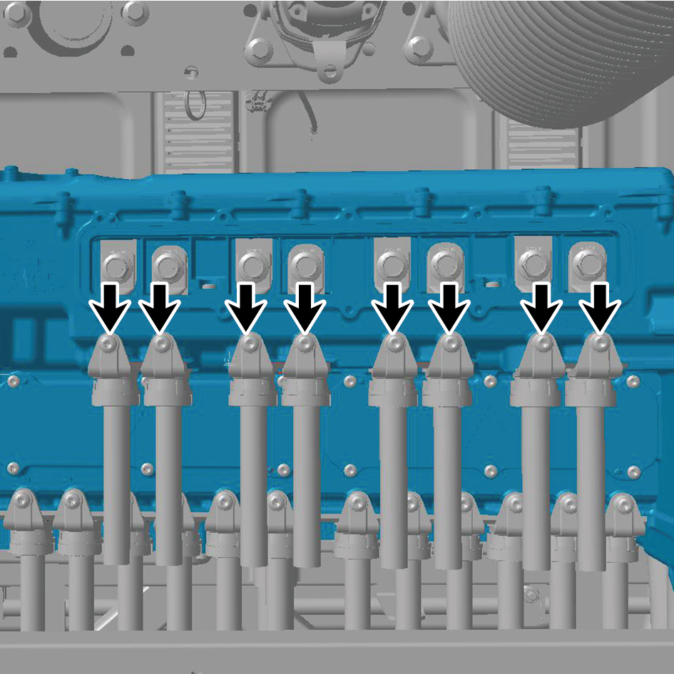
11
Remove the 8 fixing bolts of the harness.
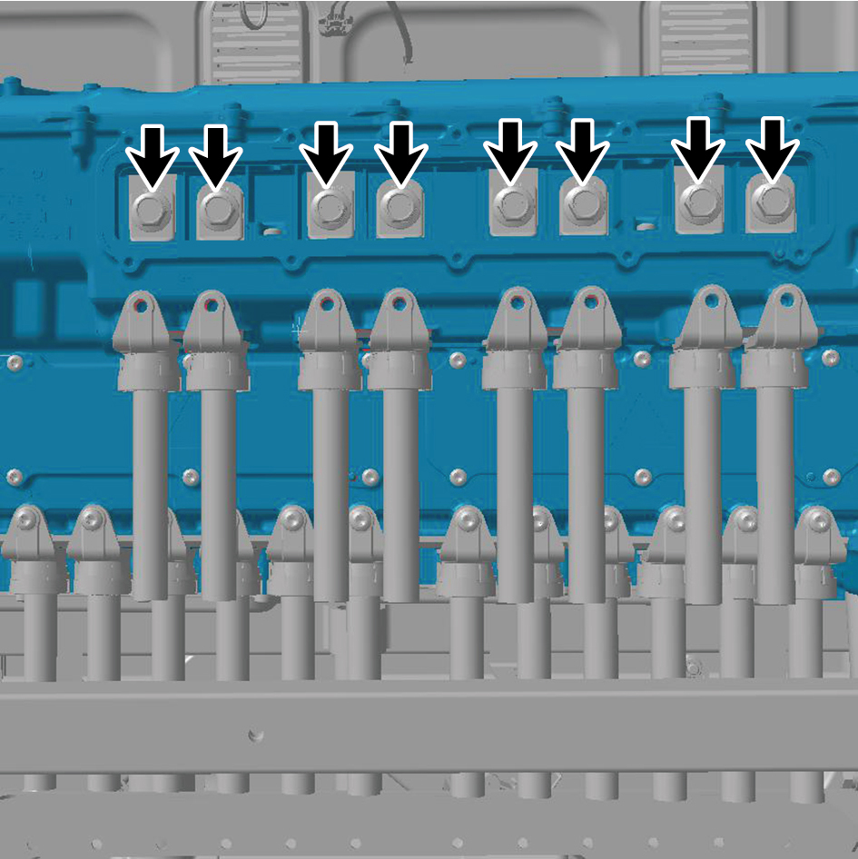
12
Remove the 12 fixing screws of the cover plate and
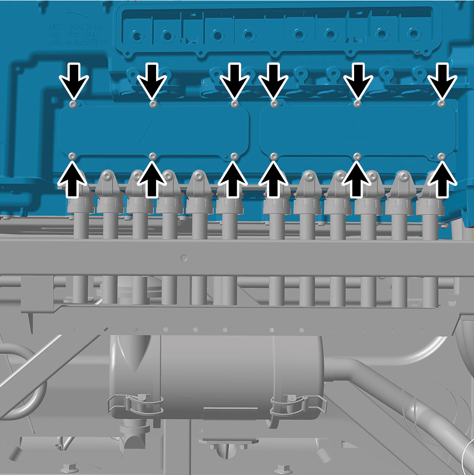
detach the 2 cover plates.
13
Remove the 12 fixing screws of the harness.
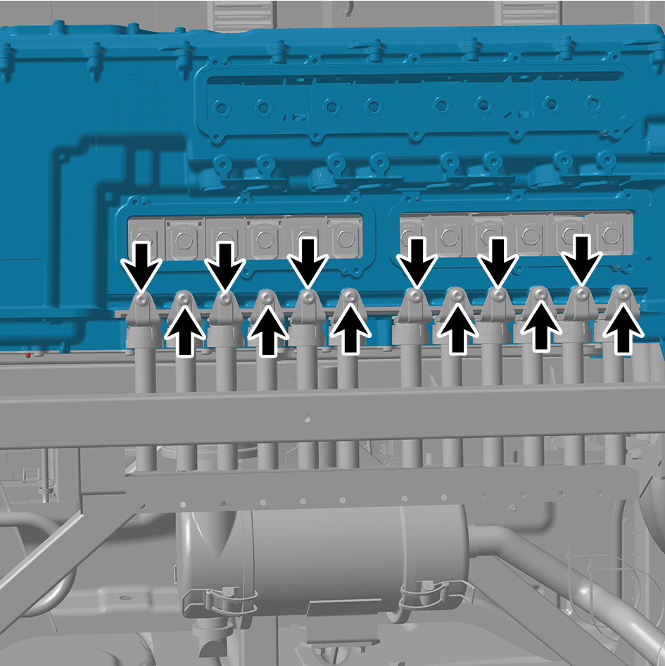
14
Remove the 12 fixing bolts of the harness.
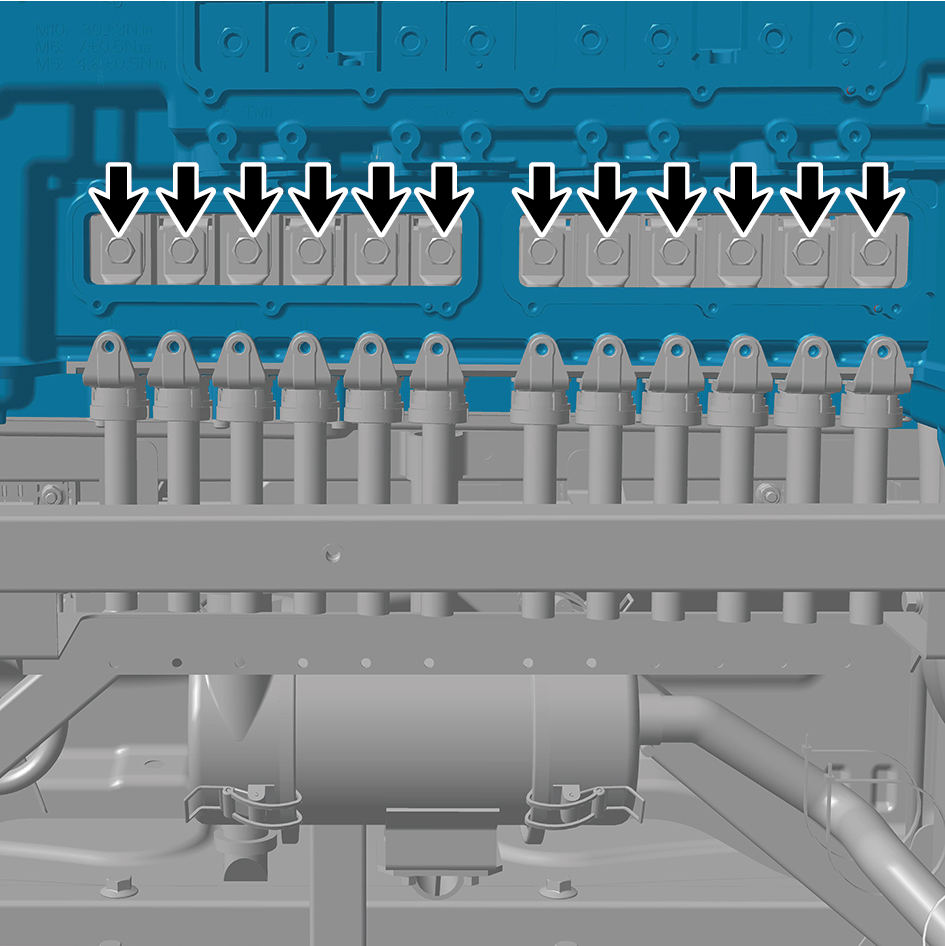
15
Disconnect the 15 harness connectors of the all-in-one
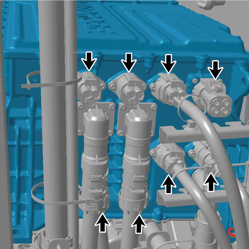
power distribution assembly.
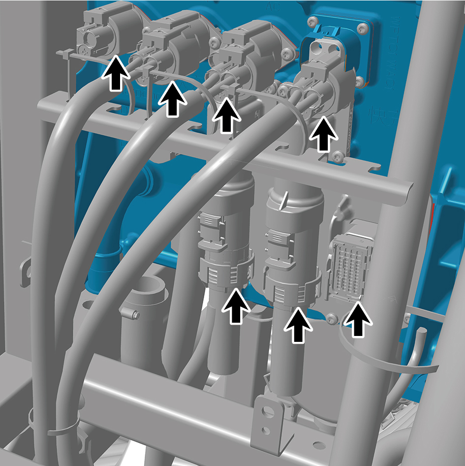
16
Disconnect the 2 water pipes.
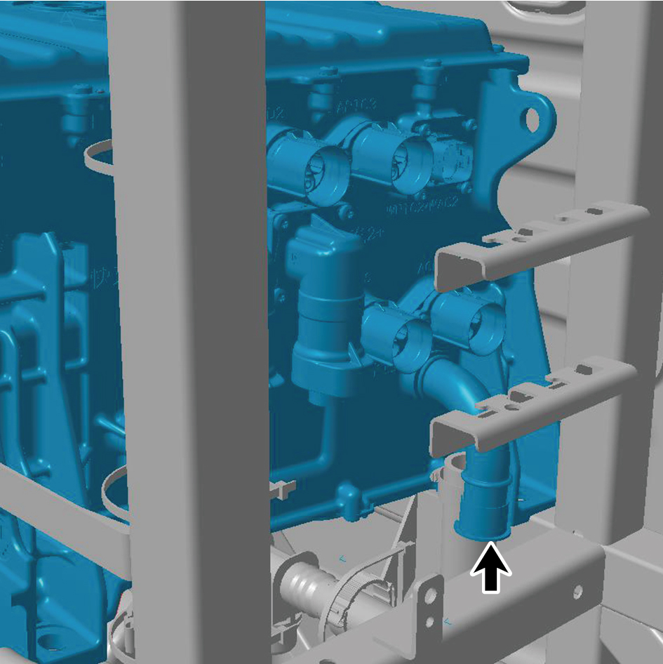
caution
Use a clean container to receive the discharged
coolant.
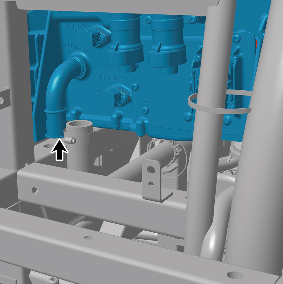
17
Remove 2 fixing bolt of the ground harness.
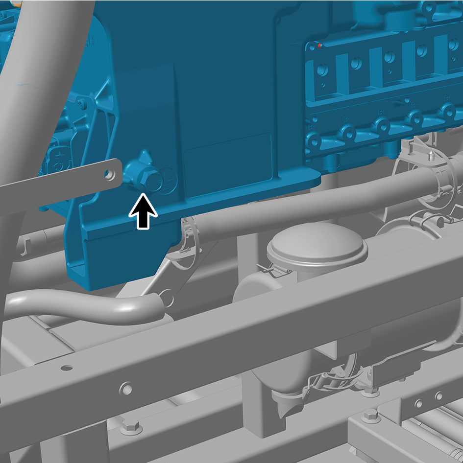
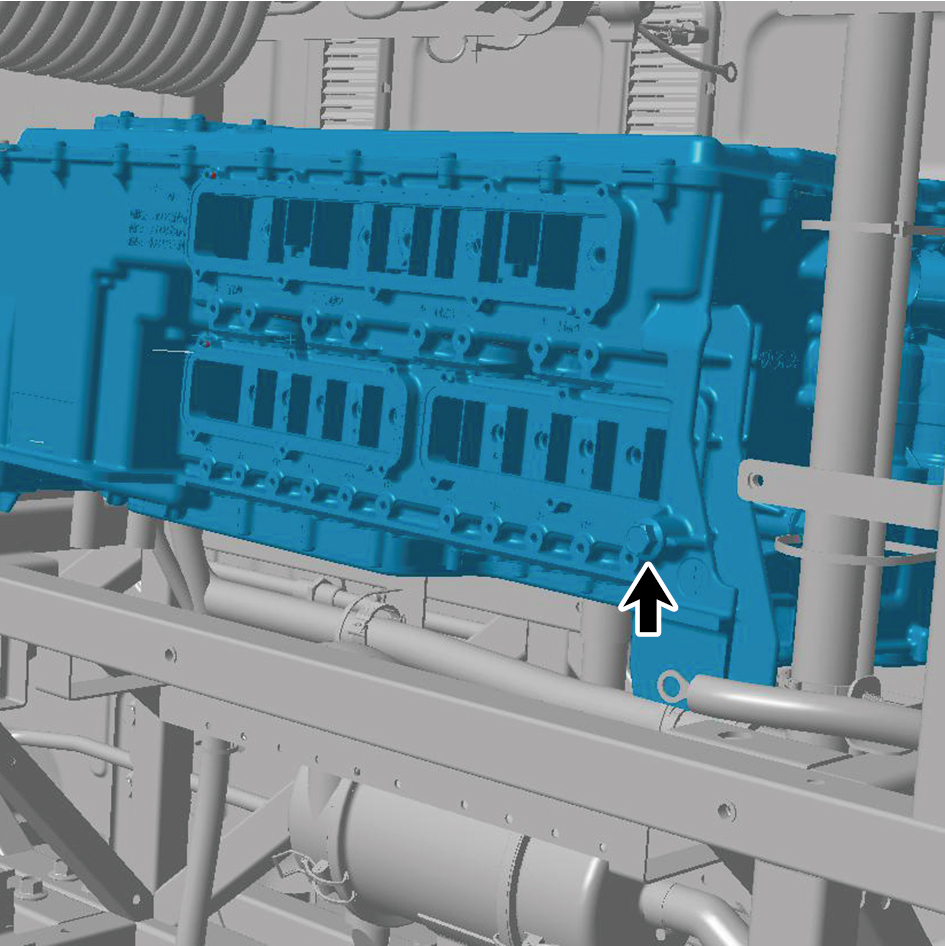
18
Remove the 4 fixing bolts of the all-in-one power
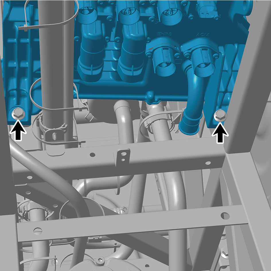
distribution assembly and detach the all-in-one power
distribution assembly.
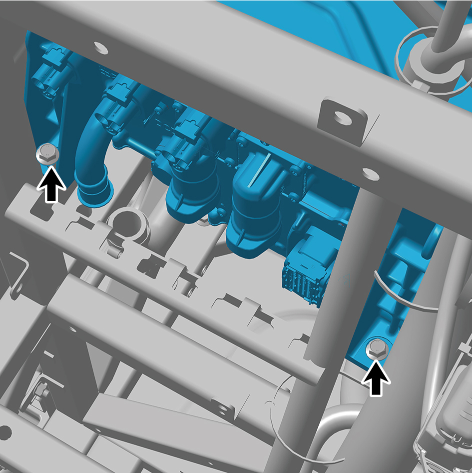
Installation Procedures
1
Move the all-in-one power distribution assembly to the
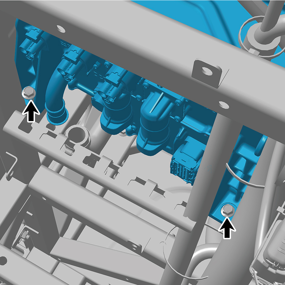
installation location.
2
Install the 4 fixing bolts of the all-in-one power distribution
assembly.
Torque:62 ft-lb +/- 6 ft-lb
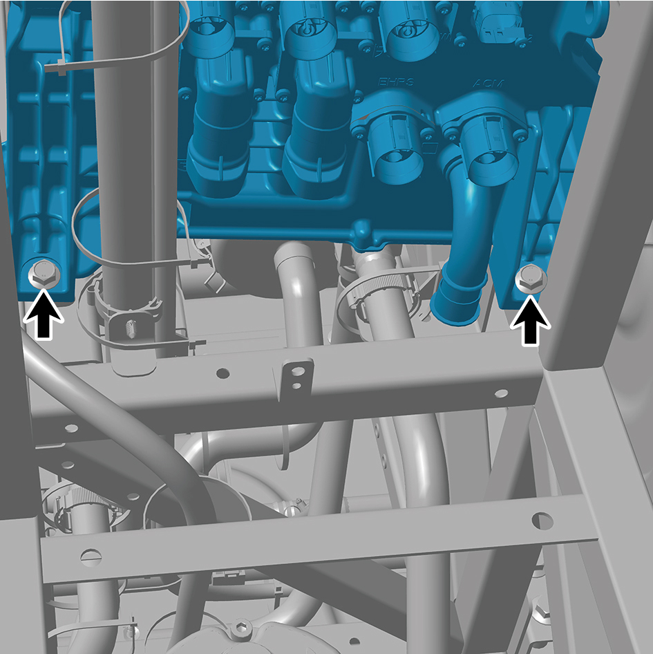
3
Install 2 fixing bolt of the ground harness.
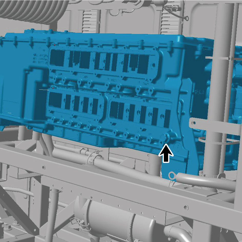
Torque:(18 ft-lb +/- 2ft-lb) ft-lb
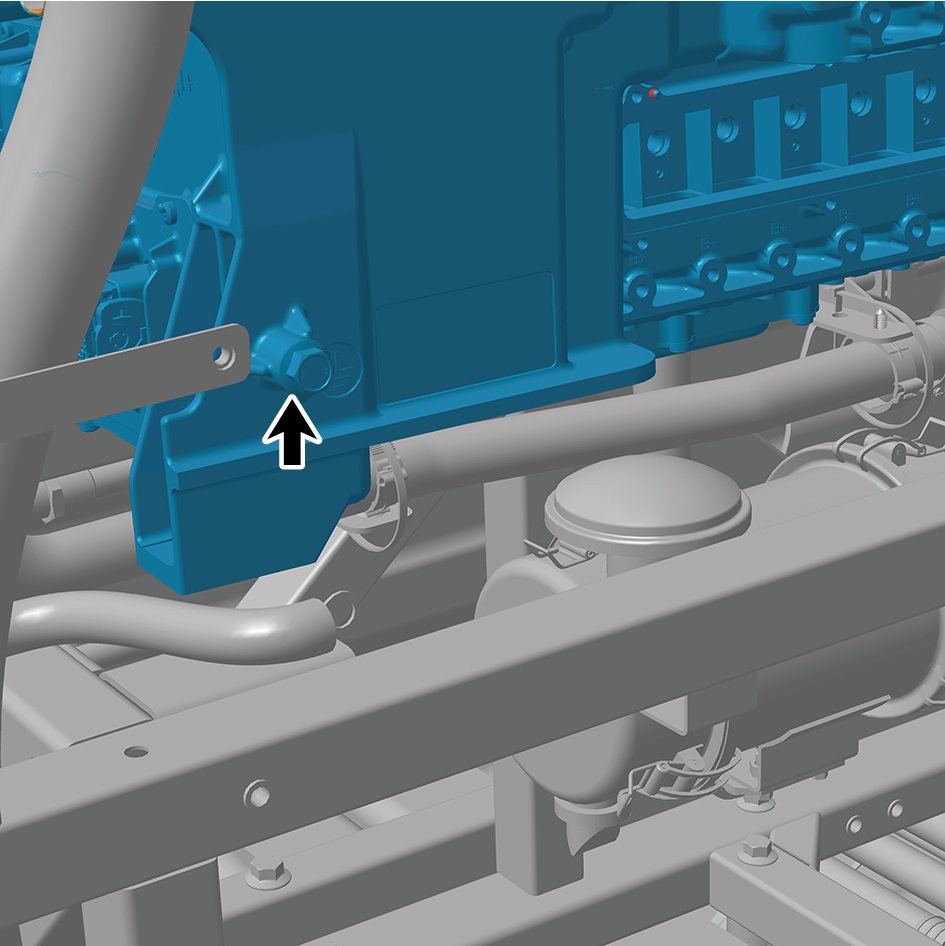
4
Connect the 2 water pipes.
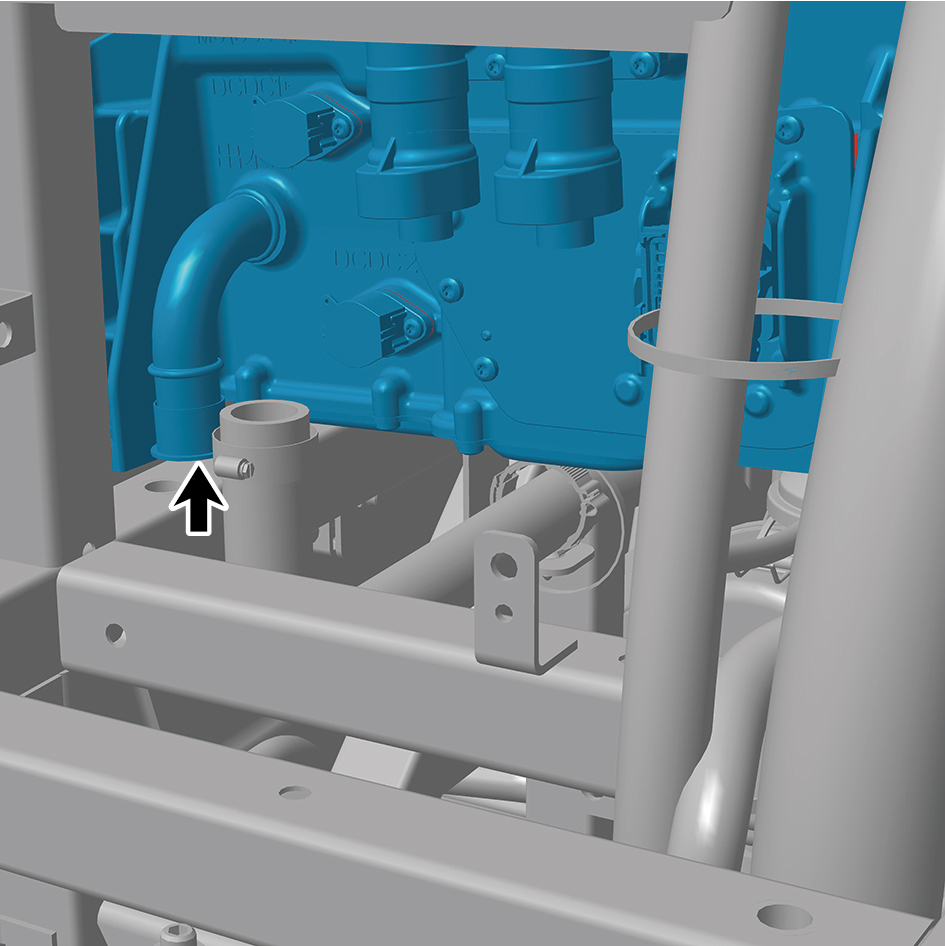
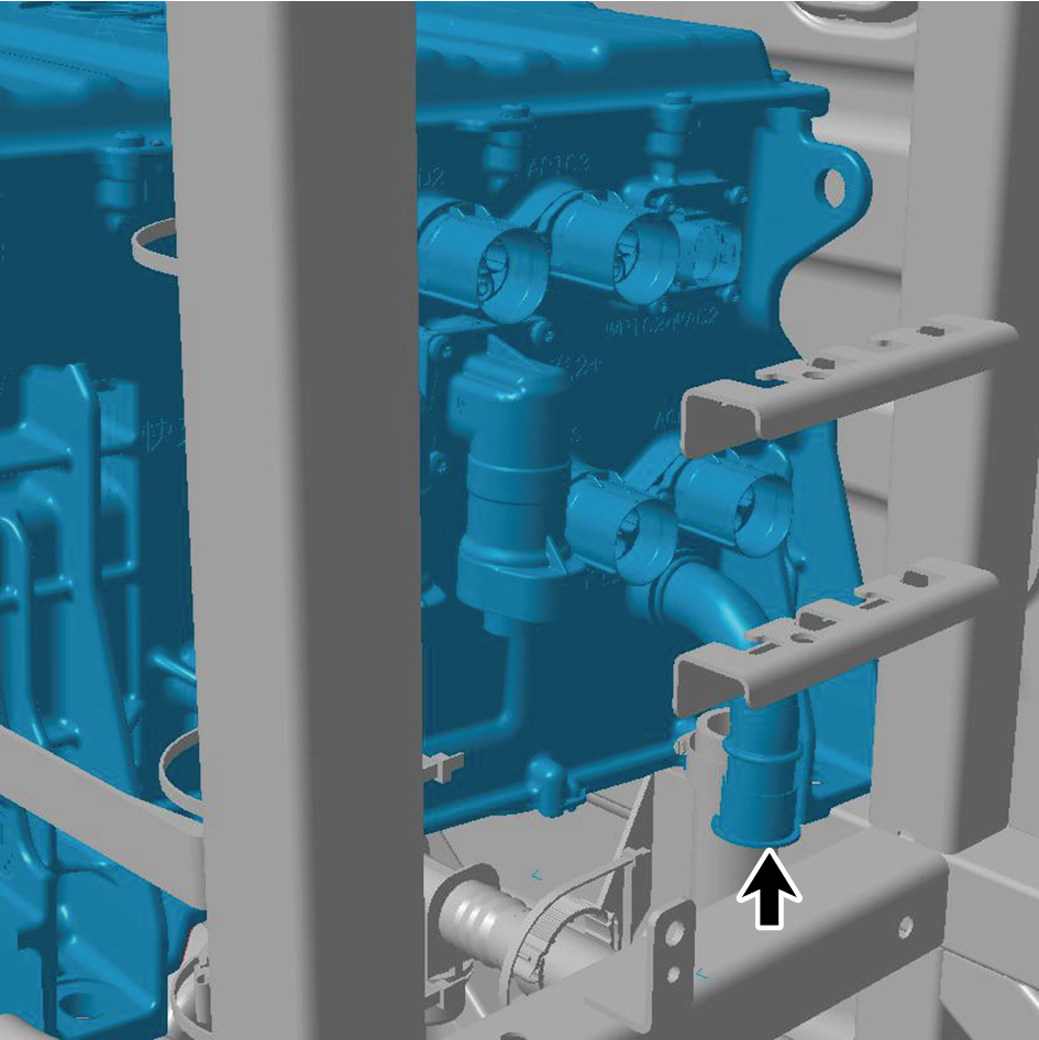
5
Connect the 15 harness connectors of the all-in-one
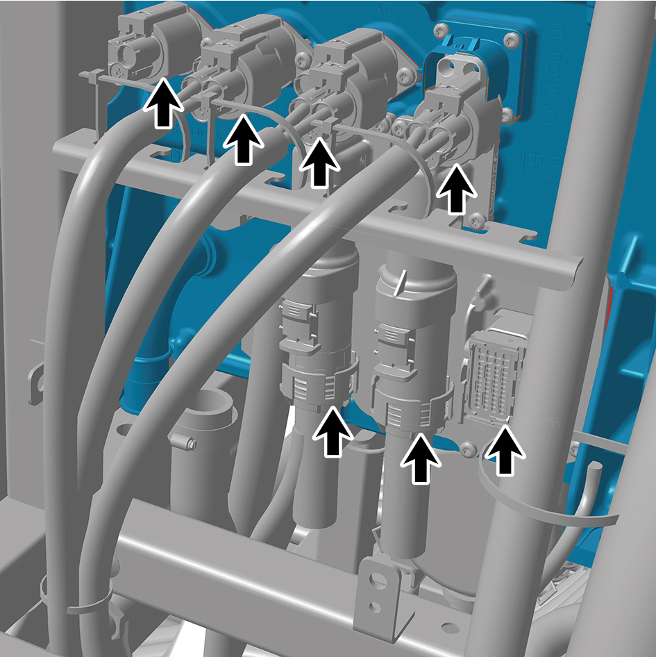
power distribution assembly.
caution
The harness is firmly connected following the
principal of "insert until a click is heard for
confirmation".
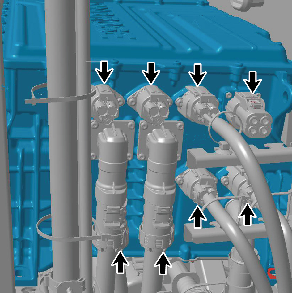
6
Install the 12 fixing bolts of the harness.
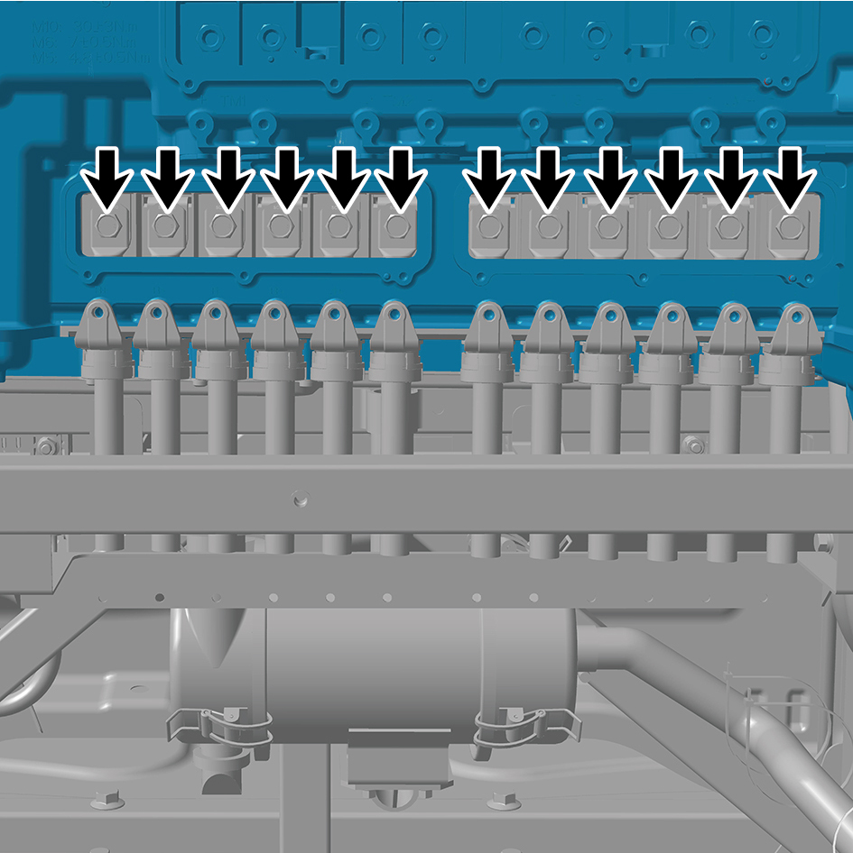
Torque: (22 ft-lb +/- 2 ft-lb) ft-lb
7
Install the 12 fixing screws of the harness.
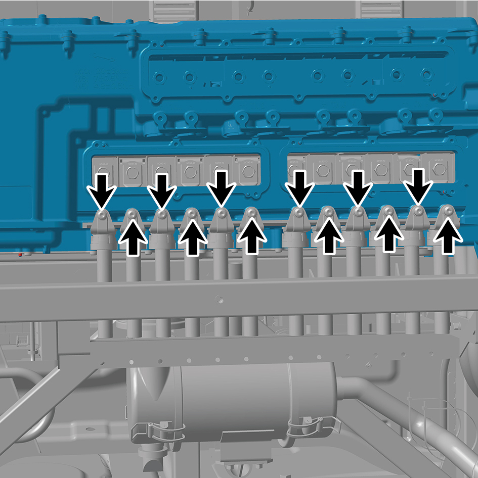
8
Install the 12 fixing screws of the cover plate.
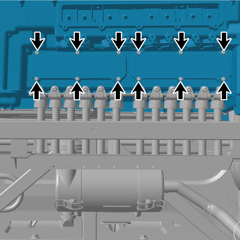
9
Install the 8 fixing bolts of the harness.
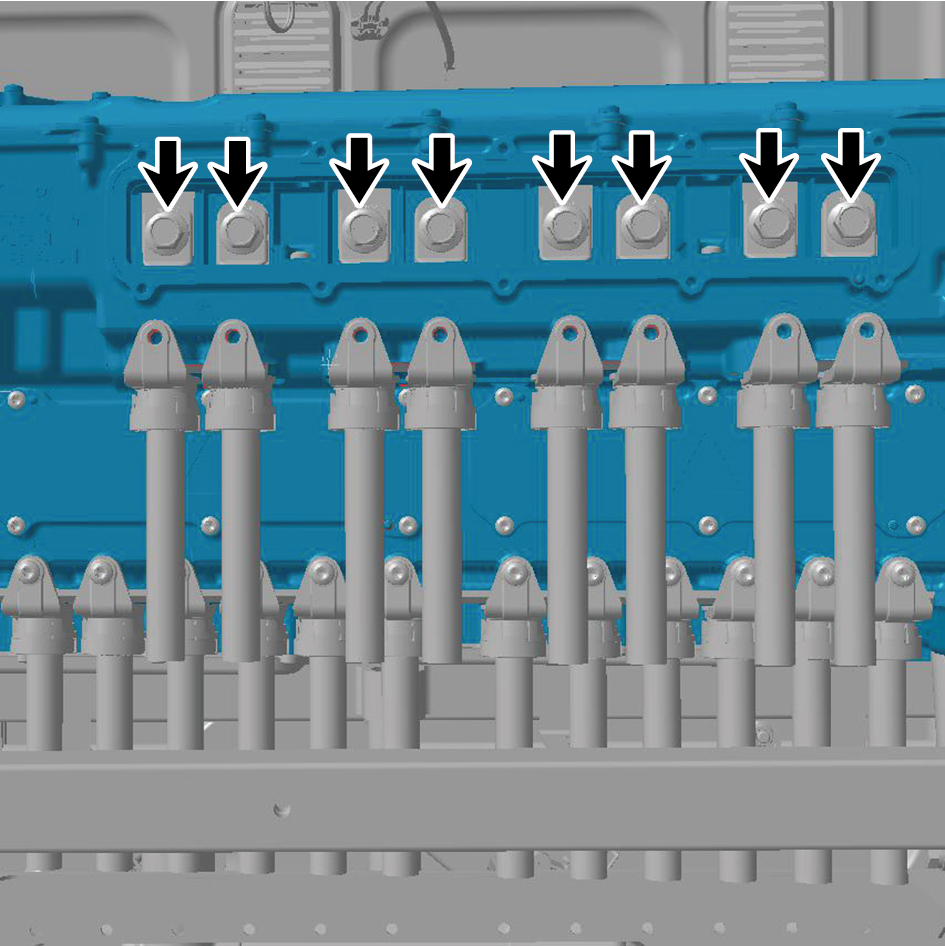
Torque: (22 ft-lb +/- 2 ft-lb) ft-lb
10
Install the 8 fixing screws of the harness.
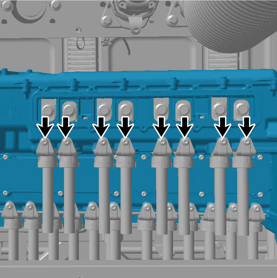
11
Install the 10 fixing screws of the cover plate.
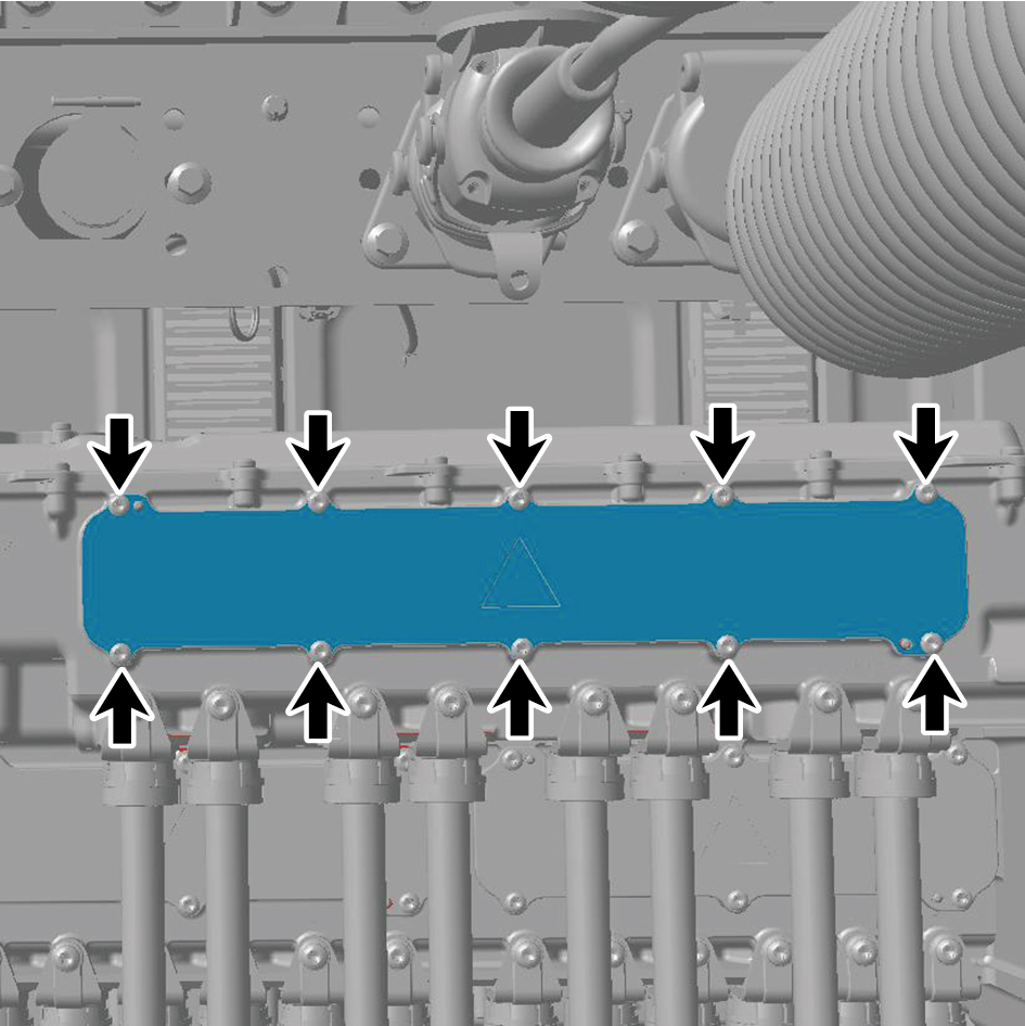
12
Install the back integrated bracket middle cover plate
assembly.
13
Install the back integrated bracket side cover plate
assembly (right).
14
Install the back integrated bracket side cover plate
assembly (left).
15
Fill coolant in the power system.
16
Perform power-on of the high voltage system.
17
Connect the battery negative cable.
18
Close the front flip cover plate.
19
Close the door.