← Back to Contents
4 New Energy Vehicle Components / 4.3 Power Battery Device | PDF pages 194-263
4.3 Power Battery Device
4.3 Power Battery Device
3. When the new energy vehicle is eligible for scrapping, it
should be sent to a company engaged in recovery and
4.3.1 Description and Operation
disassembly of scrapped vehicles approved by our
4.3.1.1 Description and Operation
company for removal of the high voltage battery.
Accident
4. The owner of high voltage battery (battery leasing and
other operating enterprises) should hand over the waste
1. Handle traffic accidents in accordance with relevant
high voltage batteries to a recycling service outlet approved
provisions of State Local and Federal law on Road Traffic
by our company.
Safety.
5. Do not disassemble, remove or discard the high voltage
2. Notify the vehicle after-sales service specialist. It is
batteries without permission. Do not hand over waste high
prohibited to reuse the vehicle before the after-sales
voltage batteries to other units or individuals. You will be
department issues the battery safety judgment results.
held responsible for any environmental pollution or safety
3. If repair or painting is required after collision of the vehicle,
accidents caused by removing, disassembling or discarding
it must be performed at an authorized dealer of the vehicle,
high voltage batteries without permission.
and it is prohibited to remove the vehicle without
Environmental Pollution
permission. Before painting, remove the high voltage
battery, high voltage harness, MCU and other high voltage
1. The electrode material of the waste battery in the
components. This is because the service life of the high
environment will go through hydrolysis, decomposition,
voltage battery can be affected when it is exposed to the
oxidation and other chemical reactions with the substances
higher temperature painting workshop. In addition, the high
in the environment, producing heavy metal ions, strong
voltage battery on the vehicle may bring potential safety
alkali and negative electrode carbon dust which will result
hazards to maintenance personnel who have not received
in heavy metal, alkali and dust pollutions.
professional training in maintenance of electric vehicles.
2. The electrolyte of waste batteries in the environment can go
Catching Fire
through hydrolysis, decomposition, combustion and other
chemical reactions, producing HF, arsenic-containing
1. Immediately turn off the emergency high voltage switch and
compounds and phosphorus-containing compounds, which
low voltage power supply, and notify the manufacturer's
will lead to fluorine and arsenic pollutions.
after-sales personnel.
3. The solvent of waste batteries undergoes hydrolysis,
2. Do not touch the leaking electrolyte with your hands; If your
combustion, decomposition and other chemical reactions,
skin or eyes come into contact with the electrolyte, rinse
producing small molecule organic compounds such as
immediately with plenty of water, and seek medical
formaldehyde, methanol, acetaldehyde, ethanol, or formic
attention immediately to avoid injury.
acid, which are easily soluble in water and can cause water
Falling in Water or Immersion in Water
pollution.
1. Do not power on the vehicle.
4. Other substances in the battery can cause organic matter
2. Contact the service personnel.
and fluorine pollutions when they are in the environment.
Recovery and Tracing of High Voltage Battery
5. When using the battery, some harmful substances
produced after side reactions, including the products of
1. Car owners and enterprises shall dispose of batteries in
solvent decomposition such as propylene, glycol, ethylene,
accordance with the Interim Measures for the Management
and ethanol, the by-products generated via reaction
of Recovery and Utilization of New Energy Vehicle High
between electrolyte and positive electrode such as HF, LiF,
Voltage Battery and the Interim Regulations on the
(CH2OCO2Li)2CH3OCO2Li, CH4, CO, and CH3OH, the
Management of Recovery, Utilization and Tracing of New
products of side reaction between the negative electrode
Energy Vehicle High Voltage Battery.
and the electrolyte, and additives added in the pretreatment
2. If repair or replacement of the high voltage battery is
process of electrode can directly or indirectly cause
required, the owner of a new energy vehicle should send
environmental pollution.
the new energy vehicle to an after-sales service
organization recognized by our company with
corresponding capabilities for repair and replacement.
Harm to Human Health
1. Ingestion of harmful components in batteries can cause
severe chemical burns to the mouth, esophagus,
gastrointestinal tract, which will lead to upper respiratory
tract and lung allergies. If you have ingested harmful
ingredients, do not induce vomiting and do not eat or drink.
Instead, you should seek medical attention immediately.
2. Skin contact and absorption of harmful components such
as ethylene carbonate, diethyl carbonate, and dimethyl
carbonate in battery packs may cause local inflammation or
skin allergies and/or chemical burns.
3. Eye contact with the harmful components of the battery
pack may cause severe allergies and chemical burns.
4.3.2 Specifications
4.3.2.1 Fastener Specifications
Range Of Torque
Specifications
Fastener name
Metric System(ft-lb)
NCM-The fixing bolts connecting the
battery pack assembly (AVIC 161Ah) to
M14
147.5 ft-lb +/- 7 ft-lb
the battery mounting bracket
NCM-The fixing bolts connecting the
battery pack assembly (AVIC 161Ah) to
M8
18 ft-lb +/- 2 ft-lb
the frame assembly
4.3.2.2 Technical Parameters
High Voltage Battery (NCM Lithium Battery)
Item
Parameter
Working environment temperature (*)
-30 - 55
Working environment relative humidity (%)
5~95
Rated capacity (Ah)
644
Nominal voltage (V)
754.8
Working voltage range (V)
571.2~887.4
SOC working range (%)
2~97
SOC at delivery (%)
50
Thermal management mode
Liquid cooling, liquid heating
Battery pack module
4P, 1P204S
Rated storage energy (kWh)
486.09
Battery model
EV-CALB-755161
Ternary lithium battery
Main features
Charging mode
DC charging
Charging current (A)
644
Charging voltage (V)
887.4
Huating (Hefei) Hybrid Technology Co., Ltd.
Manufacturer
High Voltage Battery (LFP Battery)
Item
Parameter
Working environment temperature (*)
-30~55
Working environment relative humidity (%)
5~95
Rated capacity (Ah)
920
Nominal voltage (V)
766.4
Working voltage range (V)
595~868.7
SOC working range (%)
2~100
SOC at delivery (%)
50
Item
Parameter
Thermal management mode
Liquid cooling, liquid heating
Battery pack module
4P, 1P238S
Rated storage energy (kWh)
705.2
Battery model
EV-CALB-766230
Lithium iron phosphate battery
Main features
Charging mode
DC charging
Charging current (A)
920
Charging voltage (V)
868.7
Huating (Hefei) Hybrid Technology Co., Ltd.
Manufacturer
4.3.3 System Schematic Diagram
4.3.3.1 Electrical Schematic Diagram
4.3.4 Diagnostic Information and Steps
4.3.4.1 Diagnosis Description
Before diagnosing faults in the power battery system, refer to Description And OperationUnderstanding and familiarizing oneself
with the working principle of the power battery device before starting system diagnosis can help determine the correct fault
diagnosis steps in the event of a malfunction, and more importantly, it can help determine the situation described by the customer
belongs to normal operation. Any fault diagnosis of the power battery device should start with routine inspection, guiding
maintenance personnel to take the next logical step for fault diagnosis. Understanding and correctly using the diagnostic process
can shorten the diagnosis time and avoid misjudgment of faulty parts.
4.3.4.2 Routine Inspection
• Check for aftermarket devices that may affect the operation of the power battery system, ensuring that these devices do not
affect the operation of the power battery system.
• Inspect system components that are easily accessible or visible to make sure they are not visibly damaged or have conditions
that could cause failure.
4.3.4.3 DTC Confirmation
1.Connect the diagnostic instrument to the diagnostic interface, read and record the DTC, and then clear the DTC.
2. Restart the vehicle.
3. Read the malfunction code of the control system again to confirm whether the system has a malfunction code output.
– Yes:Diagnose based on the output malfunction code.
– No:Perform intermittent malfunction checks, refer to Inspection Of Intermittent Fault
4.3.4.4 List Of Diagnostic Trouble Codes (DTCs)
CMU1
Fault Description
Exclusion Method
Fault Code
The CMU supply voltage limit is too low
B111716
- battery pack
The CMU supply voltage limit is too high
B111717
- battery pack
Refer to CMU1 Power Fault
The supply voltage of the CMU is too
P168400
low - the battery pack
The supply voltage of the CMU is too
P168500
high - the battery pack
VDC communication is lost - battery
U012287
pack
PCAN2 BusOff- battery pack
U008C88
Refer to CMU1 Communication Fault
CDCU communication lost - battery
U015687
pack
T-BOX communication is lost - battery
U019887
pack
The internal communication of the CMU
P163900
is abnormally faulty
Refer to CMU1 Internal Fault
The CMU storage state is faulty
P166600
Failure of temperature acquisition
P166700
Fault Description
Exclusion Method
Fault Code
The CMU passive equalization function
P16A100
is faulty
The battery temperature limit is too high
P160200
The temperature is too low
P160500
The temperature is too high
P163500
Refer to CMU1 Temperature
Abnormality
The temperature difference is too large
P163A00
The temperature difference is too large
P166900
The temperature is too low
P168300
The total voltage is too low
P161500
The total voltage is too high
P161600
Refer to CMU1 High Voltage Circuit
Fault
The discharge current is too large
P163600
The feedback current is too large
P166A00
Refer to CMU1 High Voltage Interlock
High voltage interlock fault
P163700
Fault
Limit undervoltage of the unit
P160300
The voltage limit of the unit is
P160400
overvoltage
The cell voltage is too low
P163300
The cell voltage is too high
P163400
The voltage dropout of the cell is too
Refer to CMU1 Individual Voltage
P163800
large
Abnormality
The loose set of the single sampling line
P166800
is faulty
The voltage dropout of the cell is too
P166B00
large
The cell voltage is too low
P166C00
The cell voltage is too high
P166D00
Refer to CMU1 Thermal Runaway
Battery pack fire alarm
P160100
Signal Fault
CMU2
Fault Description
Exclusion Method
Fault Code
The CMU supply voltage limit is too low
B111716
- battery pack
The CMU supply voltage limit is too high
Refer to CMU2 Power Fault
B111717
- battery pack
The supply voltage of the CMU is too
P178400
low - the battery pack
Fault Description
Exclusion Method
Fault Code
The supply voltage of the CMU is too
P178500
high - the battery pack
VDC communication is lost - battery
U012287
pack
PCAN2 BusOff- battery pack
U008C88
Refer to CMU2 Communication Fault
CDCU communication lost - battery
U015687
pack
T-BOX communication is lost - battery
U019887
pack
The internal communication of the CMU
P173900
is abnormally faulty
The CMU storage state is faulty
P176600
Refer to CMU2 Internal Fault
Failure of temperature acquisition
P176700
The CMU passive equalization function
P17A100
is faulty
The battery temperature limit is too high
P170200
The temperature is too low
P170500
The temperature is too high
P173500
Refer to CMU2 Temperature
Abnormality
The temperature difference is too large
P173A00
The temperature difference is too large
P176900
The temperature is too low
P178300
The total voltage is too low
P171500
The total voltage is too high
P171600
Refer to CMU2 High Voltage Circuit
Fault
The discharge current is too large
P173600
The feedback current is too large
P176A00
Refer to CMU2 High Voltage Interlock
High voltage interlock fault
P173700
Fault
Limit undervoltage of the unit
P170300
The voltage limit of the unit is
P170400
overvoltage
The cell voltage is too low
P173300
The cell voltage is too high
P173400
Refer to CMU2 Individual Voltage
The voltage dropout of the cell is too
P173800
Abnormality
large
The loose set of the single sampling line
P176800
is faulty
The voltage dropout of the cell is too
P176B00
large
The cell voltage is too low
P176C00
Fault Description
Exclusion Method
Fault Code
The cell voltage is too high
P176D00
Refer to CMU2 Thermal Runaway
Battery pack fire alarm
P170100
Signal Fault
CMU3
Fault Description
Exclusion Method
Fault Code
The CMU supply voltage limit is too low
B111716
- battery pack
The CMU supply voltage limit is too high
B111717
- battery pack
Refer to CMU3 Power Fault
The supply voltage of the CMU is too
P188400
low - the battery pack
The supply voltage of the CMU is too
P188500
high - the battery pack
VDC communication is lost - battery
U012287
pack
PCAN2 BusOff- battery pack
U008C88
Refer to CMU3 Communication Fault
CDCU communication lost - battery
U015687
pack
T-BOX communication is lost - battery
U019887
pack
The internal communication of the CMU
P183900
is abnormally faulty
The CMU storage state is faulty
P186600
Refer to CMU3 Internal Fault
Failure of temperature acquisition
P186700
The CMU passive equalization function
P18A100
is faulty
The battery temperature limit is too high
P180200
The temperature is too low
P180500
The temperature is too high
P183500
Refer to CMU3 Temperature
Abnormality
The temperature difference is too large
P183A00
The temperature difference is too large
P186900
The temperature is too low
P188300
The total voltage is too low
P181500
Over voltage
P181600
Refer to CMU3 High Voltage Circuit
Fault
The discharge current is too large
P183600
The feedback current is too large
P186A00
Refer to CMU3 High Voltage Interlock
High voltage interlock fault
P183700
Fault
Fault Description
Exclusion Method
Fault Code
Limit undervoltage of the unit
P180300
The voltage limit of the unit is
P180400
overvoltage
The cell voltage is too low
P183300
The cell voltage is too high
P183400
The voltage dropout of the cell is too
Refer to CMU3 Individual Voltage
P183800
large
Abnormality
The loose set of the single sampling line
P186800
is faulty
The voltage dropout of the cell is too
P186B00
large
The cell voltage is too low
P186C00
The cell voltage is too high
P186D00
Refer to CMU3 Thermal Runaway
Battery pack fire alarm
P180100
Signal Fault
CMU4
Fault Description
Exclusion Method
Fault Code
The CMU supply voltage limit is too low
B111716
- battery pack
The CMU supply voltage limit is too high
B111717
- battery pack
Refer to CMU4 Power Fault
The supply voltage of the CMU is too
P168400
low - the battery pack
The supply voltage of the CMU is too
P168500
high - the battery pack
VDC communication is lost - battery
U012287
pack
PCAN2 BusOff- battery pack
U008C88
Refer to CMU4 Communication Fault
CDCU communication lost - battery
U015687
pack
T-BOX communication is lost - battery
U019887
pack
The internal communication of the CMU
P193900
is abnormally faulty
The CMU storage state is faulty
P196600
Refer to CMU4 Internal Fault
Failure of temperature acquisition
P196700
The CMU passive equalization function
P19A100
is faulty
Fault Description
Exclusion Method
Fault Code
The battery temperature limit is too high
P190200
The temperature is too low
P190500
The temperature is too high
P193500
Refer to CMU4 Temperature
Abnormality
The temperature difference is too large
P193A00
The temperature difference is too large
P196900
The temperature is too low
P198300
The total voltage is too low
P191500
The total voltage is too high
P191600
Refer to CMU4 High Voltage Circuit
Fault
The discharge current is too large
P193600
The feedback current is too large
P196A00
Refer to CMU4 High Voltage Interlock
High voltage interlock fault
P193700
Fault
Limit undervoltage of the unit
P190300
The voltage limit of the unit is
P190400
overvoltage
The cell voltage is too low
P193300
The cell voltage is too high
P193400
The voltage dropout of the cell is too
P193800
Refer to Abnormal Voltage Of CMU4
large
Unit
The loose set of the single sampling line
P196800
is faulty
The voltage dropout of the cell is too
P196B00
large
The cell voltage is too low
P196C00
The cell voltage is too high
P196D00
Refer to CMU4 Thermal Runaway
Battery pack fire alarm
P190100
Signal Fault
4.3.4.5 CMU1 Power Fault
1.DTC Monitoring Logic
Description
DTC Trigger Conditions
Faulty Part
DTC Code
The CMU supply
1. Main battery
voltage limit is too low -
B111716
BATT24V <9V
2. Low voltage
battery pack
charging system
3. Wiring harness
The CMU supply
4. Upper left
voltage limit is too high
BATT24V >36
B111717
battery pack 1
- battery pack
Description
DTC Trigger Conditions
Faulty Part
DTC Code
The supply voltage of
the CMU is too low -
P168400
BATT24V < 18V
the battery pack
The supply voltage of
the CMU is too high -
P168500
BATT24V > 32V
the battery pack
2.Circuit Diagram
Emergency
VDC-1
VDC-2
high voltage
plug-in 1-B
C93-114
C94-44
B86-2
Thermal runaway
Battery pack
power E119
Wake up
signal E139
-B+ O4153
Supply B+ O415
BMS Power
17
I_C_LP
16
I_C_LP
10
I7_B_C
17
I1_LP_C
16
I1_LP_C
10
I7_C_B
Thermal runaway signal E139d
1
I_C_LP
Battery pack
-B+ O4153
Wake up power E119
1
I1_LP_C
Supply B+ O415
BMS Power
Thermal runaway signal E139a
Thermal runaway signal E139b
Wake up power E119a
Wake up power E119b
Power B+ O415a
Power B+ O415b
LP02-2
LP02-1
LP02-5
LP01-1
LP01-2
LP01-5
Upper left battery pack 1
Lower left battery pack 2
LP02-7
LP02-6
LP02-12
LP02-11
LP01-7
LP01-6
LP01-12
Identification ground Z57
Battery PCAN2-H
Battery PCAN2-L
Battery PCAN2-H
Battery PCAN2-L
Ground Z57
Ground Z57
PH02a
PL02a
PH02b
PL02b
Ground
Z57
G06
3. Diagnostic Steps
Step 1:DTC Confirmation. Refer to DTC Confirmation
Step 2:Routine Inspection. Refer to Routine Inspection
Step 3:Check if there are any other module power fault codes besides CMU1?
Check the main battery. Refer to Inspection Of The Main Battery
– Yes:
Check the low-voltage charging system. Refer to DCDC1 Low-voltage Charging System Malfunction
Next step
– No:
Step 4:Check the power and grounding harness of the upper left battery pack 1.
Step 5:Rewrite the configuration code, reload the software, and upgrade the upper left battery pack 1.
Step 6:Replace the upper left battery pack 1. Refer to Replacement Of NCM Battery Pack Assembly 1 (AVIC 161Ah)
Step 7:Clear and confirm DTC.
4.3.4.6 CMU1 Communication Fault
1.DTC Monitoring Logic
Description
DTC Trigger Conditions
Faulty Part
DTC Code
VDC communication is
VDC_TO_CMU/0x10016827x lost for more than 20s
U012287
lost - battery pack
PCAN2 BusOff-
U008C88
CMU BusOff
1.Wiring harness
battery pack
2. Upper left
CDCU communication
battery pack 1
CDCU_VDHR/0x18FEC1EExlost for more than 5s
U015687
lost - battery pack
T-BOX communication
TGW_TD_Time/0x18FEE6EExlost for more than 5s
U019887
is lost - battery pack
2.Circuit Diagram
Emergency
VDC-1
VDC-2
high voltage
plug-in 1-B
C93-114
C94-44
B86-2
Thermal runaway
Battery pack
power E119
Wake up
signal E139
-B+ O4153
Supply B+ O415
BMS Power
17
I_C_LP
16
I_C_LP
10
I7_B_C
17
I1_LP_C
16
I1_LP_C
10
I7_C_B
Thermal runaway signal E139d
1
I_C_LP
Battery pack
-B+ O4153
Wake up power E119
1
I1_LP_C
Supply B+ O415
BMS Power
Thermal runaway signal E139a
Thermal runaway signal E139b
Wake up power E119a
Wake up power E119b
Power B+ O415a
Power B+ O415b
LP02-2
LP02-1
LP02-5
LP01-1
LP01-2
LP01-5
Upper left battery pack 1
Lower left battery pack 2
LP02-7
LP02-6
LP02-12
LP02-11
LP01-7
LP01-6
LP01-12
Identification ground Z57
Battery PCAN2-H
Battery PCAN2-L
Battery PCAN2-H
Battery PCAN2-L
Ground Z57
Ground Z57
PH02a
PL02a
PH02b
PL02b
Ground
Z57
G06
3. Diagnostic Steps
Step 1:DTC Confirmation. Refer to DTC Confirmation
Step 2:Routine Inspection. Refer to Routine Inspection
Step 3:Check the PCAN2 bus communication harness. Refer to Inspection Of PCAN2 Bus Network Integrity
Step 4:Rewrite the configuration code, reload the software, and upgrade the upper left battery pack 1.
Step 5:Replace the upper left battery pack 1. Refer to Replacement Of NCM Battery Pack Assembly 1 (AVIC 161Ah)
Step 6:Clear and confirm DTC.
4.3.4.7 CMU1 Internal Fault
1.DTC Monitoring Logic
Description
DTC Trigger Conditions
Faulty Part
DTC Code
The internal
communication of the
Communication error with the CMU's internal capture
P163900
CMU is abnormally
chip
faulty
The CMU storage
The CMU storage state is faulty
P166600
1. Upper left
state is faulty
battery pack 1
Failure of temperature
Failure of temperature acquisition
P166700
acquisition
The CMU passive
equalization function is
The CMU passive equalization function is faulty
P16A100
faulty
2. Diagnostic Steps
Step 1:DTC Confirmation. Refer to DTC Confirmation
Step 2:Routine Inspection. Refer to Routine Inspection
Step 3:Rewrite the configuration code, reload the software, and upgrade the upper left battery pack 1.
Step 4:Replace the upper left battery pack 1. Refer to Replacement Of NCM Battery Pack Assembly 1 (AVIC 161Ah)
Step 5:Clear and confirm DTC.
4.3.4.8 CMU1 Temperature Abnormality
1.DTC Monitoring Logic
Description
DTC Trigger Conditions
Faulty Part
DTC Code
The battery
temperature limit is too
Tmax ≥140℉
P160200
high
The temperature is too
P160500
Tmin < -22℉
low
The temperature is too
Tmax ≥131℉
P163500
1. Upper left
high
battery pack 1
The temperature
ΔT≥77℉
P163A00
difference is too large
The temperature
ΔT≥68℉
P166900
difference is too large
The temperature is too
Tmin < -13℉
P168300
low
2. Diagnostic Steps
Step 1:DTC Confirmation. Refer to DTC Confirmation
Step 2:Routine Inspection. Refer to Routine Inspection
Step 3:Move the vehicle to a normal temperature environment and let it sit for a while.
Step 4:Check whether the vehicle has any malfunction codes related to the thermal management system?
Prioritize troubleshooting related to thermal management systems.
– Yes:
Next step
– No:
Step 5:Rewrite the configuration code, reload the software, and upgrade the upper left battery pack 1.
Step 6:Replace the upper left battery pack 1. Refer to Replacement Of NCM Battery Pack Assembly 1 (AVIC 161Ah)
Step 7:Clear and confirm DTC.
4.3.4.9 CMU1 High Voltage Circuit Fault
1.DTC Monitoring Logic
Description
DTC Trigger Conditions
Faulty Part
DTC Code
Tmin>15℃
PackVokt≤530.4V(2.6V * 204)
The total voltage is too
0℃<Tmin≤15℃PackVokt≤469.2V(2.3V * 204)
P161500
low
Tmin≤0℃
PackVokt≤387.6V(1.9V * 204)
1. High voltage
The total voltage is too
PackVokt≥877.2V (4.3V * 204)
P161600
wiring harness
high
2. Upper left
The discharge current
battery pack 1
I >1.2*Check the pulse discharge ammeter+30A
P163600
is too large
The feedback current
I >1.2*Check back the charge current meter+30A
P166A00
is too large
2. Diagnostic Steps
Step 1:DTC Confirmation. Refer to DTC Confirmation
Step 2:Routine Inspection. Refer to Routine Inspection
Step 3:Check the high-voltage harness of the upper left battery pack 1.
Step 4:Check the insulation detection circuit inside the upper left battery pack 1.
Step 5:Rewrite the configuration code, reload the software, and upgrade the upper left battery pack 1.
Step 6:Replace the upper left battery pack 1. Refer to Replacement Of NCM Battery Pack Assembly 1 (AVIC 161Ah)
Step 7:Clear and confirm DTC.
4.3.4.10 CMU1 High Voltage Interlock Fault
1.DTC Monitoring Logic
Description
DTC Trigger Conditions
Faulty Part
DTC Code
1. High voltage
wiring harness
2. High-voltage
High voltage interlock
The battery high-voltage interlock signal status is
interlocking
P163700
malfunction
abnormal
wiring harness
3. Upper left
battery pack 1
2. Diagnostic Steps
Step 1:DTC Confirmation. Refer to DTC Confirmation
Step 2:Routine Inspection. Refer to Routine Inspection
Step 3:Check the high-voltage wiring harness of each high-voltage component.
Step 4:Check the high-voltage interlock harness of each high-voltage component.
Step 5:Rewrite the configuration code, reload the software, and upgrade the upper left battery pack 1.
Step 6:Replace the upper left battery pack 1. Refer to Replacement Of NCM Battery Pack Assembly 1 (AVIC 161Ah)
Step 7:Clear and confirm DTC.
4.3.4.11 CMU1 Individual Voltage Abnormality
1.DTC Monitoring Logic
Description
DTC Trigger Conditions
Faulty Part
DTC Code
Tmin>59℉
Vmin≤2.2V
Limit undervoltage of
32℉<Tmin≤59℉Vmin≤2.0V
P160300
the unit
Tmin≤32℉
Vmin≤1.8V
The voltage limit of the
Vmax≥4.4V
P160400
unit is overvoltage
Tmin>59℉
Vmin≤2.6V
The cell voltage is too
32℉<Tmin≤59℉Vmin≤2.3V
P163300
low
Tmin≤32℉
Vmin≤1.9V
The cell voltage is too
Vmax≥4.37V
P163400
high
1. Upper left
battery pack 1
The voltage dropout of
ΔV≥650mV
P163800
the cell is too large
The loose set of the
single sampling line is
The fault flag of single collection disconnection is 1
P166800
faulty
The voltage dropout of
ΔV≥500mv
P166B00
the cell is too large
Tmin>59℉
Vmin≤3.28V
The cell voltage is too
32℉<Tmin≤59℉Vmin≤3.19V
P166C00
low
Tmin≤32℉
Vmin≤2.21V
Description
DTC Trigger Conditions
Faulty Part
DTC Code
The cell voltage is too
Vmax≥4.316v
P166D00
high
2. Diagnostic Steps
Step 1:DTC Confirmation. Refer to DTC Confirmation
Step 2:Routine Inspection. Refer to Routine Inspection
Step 3:Rewrite the configuration code, reload the software, and upgrade the upper left battery pack 1.
Step 4:Replace the upper left battery pack 1. Refer to Replacement Of NCM Battery Pack Assembly 1 (AVIC 161Ah)
Step 5:Clear and confirm DTC.
4.3.4.12 CMU1 Thermal Runaway Signal Fault
1.DTC Monitoring Logic
Description
DTC Trigger Conditions
Faulty Part
DTC Code
The thermal runaway fault flag in the packet is 1 or the
1.Wiring harness
2. Upper left
Battery pack fire alarm
VDC receives the CMU thermal runaway wake-up
P160100
hardwire signal
battery pack 1
2.Circuit Diagram
Emergency
VDC-1
VDC-2
high voltage
plug-in 1-B
C93-114
C94-44
B86-2
Thermal runaway
Battery pack
power E119
Wake up
signal E139
-B+ O4153
Supply B+ O415
BMS Power
17
I_C_LP
16
I_C_LP
10
I7_B_C
17
I1_LP_C
16
I1_LP_C
10
I7_C_B
Thermal runaway signal E139d
1
I_C_LP
Battery pack
-B+ O4153
Wake up power E119
1
I1_LP_C
Supply B+ O415
BMS Power
Thermal runaway signal E139a
Thermal runaway signal E139b
Wake up power E119a
Wake up power E119b
Power B+ O415a
Power B+ O415b
LP02-2
LP02-1
LP02-5
LP01-1
LP01-2
LP01-5
Upper left battery pack 1
Lower left battery pack 2
LP02-7
LP02-6
LP02-12
LP02-11
LP01-7
LP01-6
LP01-12
Identification ground Z57
Battery PCAN2-H
Battery PCAN2-L
Battery PCAN2-H
Battery PCAN2-L
Ground Z57
Ground Z57
PH02a
PL02a
PH02b
PL02b
Ground
Z57
G06
3. Diagnostic Steps
Step 1:DTC Confirmation. Refer to DTC Confirmation
Step 2:Routine Inspection. Refer to Routine Inspection
Step 3:Check if the vehicle is experiencing thermal runaway?
A.
Stop vehicle charging operations immediately.
B.
Park the vehicle in a suitable temperature environment and let it sit.
– Yes:
C.
Execute the operation to release the high voltage system.
D.
Check vehicle thermal management system malfunction codes.
Next step
– No:
Step 4:Check the thermal runaway signal harness of the upper left battery pack 1.
Step 5:Rewrite the configuration code, reload the software, and upgrade the upper left battery pack 1.
Step 6:Replace the upper left battery pack 1. Refer to Replacement Of NCM Battery Pack Assembly 1 (AVIC 161Ah)
Step 7:Clear and confirm DTC.
4.3.4.13 CMU2 Power Fault
1.DTC Monitoring Logic
Description
DTC Trigger Conditions
Faulty Part
DTC Code
The CMU supply
voltage limit is too low -
B111716
BATT24V <9V
battery pack
The CMU supply
1. Main battery
voltage limit is too high
BATT24V >36
B111717
2. Low voltage
- battery pack
charging system
3. Wiring harness
The supply voltage of
4. Lower left
the CMU is too low -
P178400
BATT24V < 18V
battery pack 2
the battery pack
The supply voltage of
the CMU is too high -
P178500
BATT24V > 32V
the battery pack
2.Circuit Diagram
Emergency
VDC-1
VDC-2
high voltage
plug-in 1-B
C93-114
C94-44
B86-2
Thermal runaway
Battery pack
power E119
Wake up
signal E139
-B+ O4153
Supply B+ O415
BMS Power
17
I_C_LP
16
I_C_LP
10
I7_B_C
17
I1_LP_C
16
I1_LP_C
10
I7_C_B
Thermal runaway signal E139d
1
I_C_LP
Battery pack
-B+ O4153
Wake up power E119
1
I1_LP_C
Supply B+ O415
BMS Power
Thermal runaway signal E139a
Thermal runaway signal E139b
Wake up power E119a
Wake up power E119b
Power B+ O415a
Power B+ O415b
LP02-2
LP02-1
LP02-5
LP01-1
LP01-2
LP01-5
Upper left battery pack 1
Lower left battery pack 2
LP02-7
LP02-6
LP02-12
LP02-11
LP01-7
LP01-6
LP01-12
Identification ground Z57
Battery PCAN2-H
Battery PCAN2-L
Battery PCAN2-H
Battery PCAN2-L
Ground Z57
Ground Z57
PH02a
PL02a
PH02b
PL02b
Ground
Z57
G06
3. Diagnostic Steps
Step 1:DTC Confirmation. Refer to DTC Confirmation
Step 2:Routine Inspection. Refer to Routine Inspection
Step 3:Check if there are any other module power fault codes besides CMU2?
Check the main battery. Refer to Inspection Of The Main Battery
– Yes:
Check the low-voltage charging system. Refer to DCDC1 Low-voltage Charging System Malfunction
Next step
– No:
Step 4:Check the power and grounding harness of the lower left battery pack 2.
Step 5:Rewrite the configuration code, reload the software, and upgrade the lower left battery pack 2.
Step 6:Replace the lower left battery pack 2. Refer to Replacement Of NCM Battery Pack Assembly 2 (AVIC 161Ah)
Step 7:Clear and confirm DTC.
4.3.4.14 CMU2 Communication Fault
1.DTC Monitoring Logic
Description
DTC Trigger Conditions
Faulty Part
DTC Code
VDC communication is
VDC_TO_CMU/0x10016827x lost for more than 20s
U012287
lost - battery pack
PCAN2 BusOff-
U008C88
CMU BusOff
1.Wiring harness
battery pack
2. Lower left
CDCU communication
battery pack 2
CDCU_VDHR/0x18FEC1EExlost for more than 5s
U015687
lost - battery pack
T-BOX communication
TGW_TD_Time/0x18FEE6EExlost for more than 5s
U019887
is lost - battery pack
2.Circuit Diagram
Emergency
VDC-1
VDC-2
high voltage
plug-in 1-B
C93-114
C94-44
B86-2
Thermal runaway
Battery pack
power E119
Wake up
signal E139
-B+ O4153
Supply B+ O415
BMS Power
17
I_C_LP
16
I_C_LP
10
I7_B_C
17
I1_LP_C
16
I1_LP_C
10
I7_C_B
Thermal runaway signal E139d
1
I_C_LP
Battery pack
-B+ O4153
Wake up power E119
1
I1_LP_C
Supply B+ O415
BMS Power
Thermal runaway signal E139a
Thermal runaway signal E139b
Wake up power E119a
Wake up power E119b
Power B+ O415a
Power B+ O415b
LP02-2
LP02-1
LP02-5
LP01-1
LP01-2
LP01-5
Upper left battery pack 1
Lower left battery pack 2
LP02-7
LP02-6
LP02-12
LP02-11
LP01-7
LP01-6
LP01-12
Identification ground Z57
Battery PCAN2-H
Battery PCAN2-L
Battery PCAN2-H
Battery PCAN2-L
Ground Z57
Ground Z57
PH02a
PL02a
PH02b
PL02b
Ground
Z57
G06
3. Diagnostic Steps
Step 1:DTC Confirmation. Refer to DTC Confirmation
Step 2:Routine Inspection. Refer to Routine Inspection
Step 3:Check the PCAN2 bus communication harness. Refer to Inspection Of PCAN2 Bus Network Integrity
Step 4:Rewrite the configuration code, reload the software, and upgrade the lower left battery pack 2.
Step 5:Replace the lower left battery pack 2. Refer to Replacement Of NCM Battery Pack Assembly 2 (AVIC 161Ah)
Step 6:Clear and confirm DTC.
4.3.4.15 CMU2 Internal Fault
1.DTC Monitoring Logic
Description
DTC Trigger Conditions
Faulty Part
DTC Code
The internal
communication of the
Communication error with the CMU's internal capture
P173900
CMU is abnormally
chip
faulty
The CMU storage
The CMU storage state is faulty
P176600
1. Lower left
state is faulty
battery pack 2
Failure of temperature
Failure of temperature acquisition
P176700
acquisition
The CMU passive
equalization function is
The CMU passive equalization function is faulty
P17A100
faulty
2. Diagnostic Steps
Step 1:DTC Confirmation. Refer to DTC Confirmation
Step 2:Routine Inspection. Refer to Routine Inspection
Step 3:Rewrite the configuration code, reload the software, and upgrade the lower left battery pack 2.
Step 4:Replace the lower left battery pack 2. Refer to Replacement Of NCM Battery Pack Assembly 2 (AVIC 161Ah)
Step 5:Clear and confirm DTC.
4.3.4.16 CMU2 Temperature Abnormality
1.DTC Monitoring Logic
Description
DTC Trigger Conditions
Faulty Part
DTC Code
The battery
temperature limit is too
Tmax ≥140℉
P170200
high
The temperature is too
P170500
Tmin < -22℉
low
The temperature is too
Tmax ≥131℉
P173500
1. Lower left
high
battery pack 2
The temperature
ΔT≥77℉
P173A00
difference is too large
The temperature
ΔT≥68℉
P176900
difference is too large
The temperature is too
Tmin < -13℉
P178300
low
2. Diagnostic Steps
Step 1:DTC Confirmation. Refer to DTC Confirmation
Step 2:Routine Inspection. Refer to Routine Inspection
Step 3:Move the vehicle to a normal temperature environment and let it sit for a while.
Step 4:Check if the vehicle has any malfunction codes related to the thermal management system?
Prioritize troubleshooting related to thermal management systems.
– Yes:
Next step
– No:
Step 5:Rewrite the configuration code, reload the software, and upgrade the lower left battery pack 2.
Step 6:Replace the lower left battery pack 2. Refer to Replacement Of NCM Battery Pack Assembly 2 (AVIC 161Ah)
Step 7:Clear and confirm DTC.
4.3.4.17 CMU2 High Voltage Circuit Fault
1.DTC Monitoring Logic
Description
DTC Trigger Conditions
Faulty Part
DTC Code
Tmin>59℉
PackVokt≤530.4V(2.6V * 204)
The total voltage is too
32℉<Tmin≤59℉PackVokt≤469.2V(2.3V * 204)
P171500
low
Tmin≤32℉
PackVokt≤387.6V(1.9V * 204)
1. High voltage
The total voltage is too
PackVokt≥877.2V (4.3V * 204)
P171600
wiring harness
high
2. Lower left
The discharge current
battery pack 2
I >1.2*Check the pulse discharge ammeter+30A
P173600
is too large
The feedback current
I >1.2*Check back the charge current meter+30A
P176A00
is too large
2. Diagnostic Steps
Step 1:DTC Confirmation. Refer to DTC Confirmation
Step 2:Routine Inspection. Refer to Routine Inspection
Step 3:Check the high voltage harness of the lower left battery pack 2.
Step 4:Check the internal insulation detection circuit of the lower left battery pack 2.
Step 5:Rewrite the configuration code, reload the software, and upgrade the lower left battery pack 2.
Step 6:Replace the lower left battery pack 2. Refer to Replacement Of NCM Battery Pack Assembly 2 (AVIC 161Ah)
Step 7:Clear and confirm DTC.
4.3.4.18 CMU2 High Voltage Interlock Fault
1.DTC Monitoring Logic
Description
DTC Trigger Conditions
Faulty Part
DTC Code
1. High voltage
wiring harness
2. High-voltage
High voltage interlock
The battery high-voltage interlock signal status is
interlocking
P173700
malfunction
abnormal
wiring harness
3. Lower left
battery pack 2
2. Diagnostic Steps
Step 1:DTC Confirmation. Refer to DTC Confirmation
Step 2:Routine inspection. Refer to Routine inspection
Step 3:Check the high-voltage wiring harness of each high-voltage component.
Step 4:Check the high-voltage interlock harness of each high-voltage component.
Step 5:Rewrite the configuration code, reload the software, and upgrade the lower left battery pack 2.
Step 6:Replace the lower left battery pack 2. Refer to Replacement Of NCM Battery Pack Assembly 2 (AVIC 161Ah)
Step 7:Clear and confirm DTC.
4.3.4.19 CMU2 Individual Voltage Abnormality
1.DTC Monitoring Logic
Description
DTC Trigger Conditions
Faulty Part
DTC Code
Tmin>59℉
Vmin≤2.2V
Limit undervoltage of
32℉<Tmin≤59℉Vmin≤2.0V
P170300
the unit
Tmin≤32℉
Vmin≤1.8V
The voltage limit of the
Vmax≥4.4V
P170400
unit is overvoltage
Tmin>59℉
Vmin≤2.6V
The cell voltage is too
32℉<Tmin≤59℉Vmin≤2.3V
P173300
low
Tmin≤32℉
Vmin≤1.9V
The cell voltage is too
Vmax≥4.37V
P173400
high
1. Lower left
battery pack 2
The voltage dropout of
ΔV≥650mV
P173800
the cell is too large
The loose set of the
single sampling line is
The fault flag of single collection disconnection is 1
P176800
faulty
The voltage dropout of
ΔV≥500mv
P176B00
the cell is too large
Tmin>59℉
Vmin≤3.28V
The cell voltage is too
32℉<Tmin≤59℉Vmin≤3.19V
P176C00
low
Tmin≤32℉
Vmin≤2.21V
Description
DTC Trigger Conditions
Faulty Part
DTC Code
The cell voltage is too
Vmax≥4.316v
P176D00
high
2. Diagnostic Steps
Step 1:DTC Confirmation. Refer to DTC Confirmation
Step 2:Routine Inspection. Refer to Routine Inspection
Step 3:Rewrite the configuration code, reload the software, and upgrade the lower left battery pack 2.
Step 4:Replace the lower left battery pack 2. Refer to Replacement Of NCM Battery Pack Assembly 2 (AVIC 161Ah)
Step 5:Clear and confirm DTC.
4.3.4.20 CMU2 Thermal Runaway Signal Fault
1.DTC Monitoring Logic
Description
DTC Trigger Conditions
Faulty Part
DTC Code
The thermal runaway fault flag in the packet is 1 or the
1.Wiring harness
2. Lower left
Battery pack fire alarm
VDC receives the CMU thermal runaway wake-up
P170100
hardwire signal
battery pack 2
2.Circuit Diagram
Emergency
VDC-1
VDC-2
high voltage
plug-in 1-B
C93-114
C94-44
B86-2
Thermal runaway
Battery pack
power E119
Wake up
signal E139
-B+ O4153
Supply B+ O415
BMS Power
17
I_C_LP
16
I_C_LP
10
I7_B_C
17
I1_LP_C
16
I1_LP_C
10
I7_C_B
Thermal runaway signal E139d
1
I_C_LP
Battery pack
-B+ O4153
Wake up power E119
1
I1_LP_C
Supply B+ O415
BMS Power
Thermal runaway signal E139a
Thermal runaway signal E139b
Wake up power E119a
Wake up power E119b
Power B+ O415a
Power B+ O415b
LP02-2
LP02-1
LP02-5
LP01-1
LP01-2
LP01-5
Upper left battery pack 1
Lower left battery pack 2
LP02-7
LP02-6
LP02-12
LP02-11
LP01-7
LP01-6
LP01-12
Identification ground Z57
Battery PCAN2-H
Battery PCAN2-L
Battery PCAN2-H
Battery PCAN2-L
Ground Z57
Ground Z57
PH02a
PL02a
PH02b
PL02b
Ground
Z57
G06
3. Diagnostic Steps
Step 1:DTC Confirmation. Refer to DTC Confirmation
Step 2:Routine Inspection. Refer to Routine Inspection
Step 3:Check if the vehicle is experiencing thermal runaway?
A.
Stop vehicle charging operations immediately.
B.
Park the vehicle in a suitable temperature environment and let it sit.
– Yes:
C.
Execute the operation to release the high voltage system.
D.
Check vehicle thermal management system malfunction codes.
Next step
– No:
Step 4:Check the lower left battery pack 2 thermal runaway signal harness.
Step 5:Rewrite the configuration code, reload the software, and upgrade the lower left battery pack 2.
Step 6:Replace the lower left battery pack 2. Refer to Replacement Of NCM Battery Pack Assembly 2 (AVIC 161Ah)
Step 7:Clear and confirm DTC.
4.3.4.21 CMU3 Power Fault
1.DTC Monitoring Logic
Description
DTC trigger Conditions
Faulty Part
DTC Code
The CMU supply
voltage limit is too low -
B111716
BATT24V <9V
battery pack
The CMU supply
1. Main battery
voltage limit is too high
BATT24V >36
B111717
2. Low voltage
- battery pack
charging system
3. Wiring harness
The supply voltage of
4. Upper right
the CMU is too low -
P188400
BATT24V < 18V
battery pack 3
the battery pack
The supply voltage of
the CMU is too high -
P188500
BATT24V > 32V
the battery pack
2.Circuit Diagram
VDC-1
VDC-2
C93-115
C94-44
Wake up power E147a
BMS Power Supply
Thermal runaway
B+ O4153
signal E139
1
I_C_RP
17
I_C_RP
16
I_C_RP
1
I1_RP_C
17
I1_RP_C
16
I1_RP_C
Thermal runaway
power E147a
Supply B+ O415d
Wake up
BMS Power
signal E139d
Thermal runaway signal E139d
Thermal runaway signal E139e
Wake up power E147a
Wake up power E147b
Power B+ O415d
Power B+ O415e
RP02-2
RP01-1
RP01-2
RP02-1
RP01-5
RP02-5
Upper right battery pack 3
Lower right battery pack 4
RP01-7
RP01-6 RP01-12
RP02-7
RP02-6
RP02-12
RP01-10
RP02-10
RP02-11
Identification ground Z57
Identification ground Z57
Identification ground Z57
Battery PCAN2-L
Battery PCAN2-H
Battery PCAN2-L
Battery PCAN2-H
Ground Z57
Ground Z57
PL02d
PH02d
PL02e
PH02e
Ground
Z57
G06
3. Diagnostic Steps
Step 1:DTC Confirmation. Refer to DTC Confirmation
Step 2:Routine Inspection. Refer to Routine Inspection
Step 3:Check if there are any other module power fault codes besides CMU3?
Check the main battery. Refer to Inspection Of The Main Battery
– Yes:
Check the low-voltage charging system. Refer to DCDC1 Low-voltage Charging System Malfunction
Next step
– No:
Step 4:Check the power and grounding harness of the upper right battery pack 3.
Step 5:Rewrite the configuration code, reload the software, and upgrade the upper right battery pack 3.
Step 6:Replace the upper right battery pack 3. Refer to Replacement Of NCM Battery Pack Assembly 2 (AVIC 161Ah)
Step 7:Clear and confirm DTC.
4.3.4.22 CMU3 Communication Fault
1.DTC Monitoring Logic
Description
DTC Trigger Conditions
Faulty Part
DTC Code
VDC communication is
VDC_TO_CMU/0x10016827x lost for more than 20s
U012287
lost - battery pack
PCAN2 BusOff-
U008C88
CMU BusOff
1.Wiring harness
battery pack
2. Upper right
CDCU communication
battery pack 3
CDCU_VDHR/0x18FEC1EExlost for more than 5s
U015687
lost - battery pack
T-BOX communication
TGW_TD_Time/0x18FEE6EExlost for more than 5s
U019887
is lost - battery pack
2.Circuit Diagram
VDC-1
VDC-2
C93-115
C94-44
Wake up power E147a
BMS Power Supply
Thermal runaway
B+ O4153
signal E139
1
I_C_RP
17
I_C_RP
16
I_C_RP
1
I1_RP_C
17
I1_RP_C
16
I1_RP_C
Thermal runaway
power E147a
Supply B+ O415d
Wake up
BMS Power
signal E139d
Thermal runaway signal E139d
Thermal runaway signal E139e
Wake up power E147a
Wake up power E147b
Power B+ O415d
Power B+ O415e
RP02-2
RP01-1
RP01-2
RP02-1
RP01-5
RP02-5
Upper right battery pack 3
Lower right battery pack 4
RP01-7
RP01-6 RP01-12
RP02-7
RP02-6
RP02-12
RP01-10
RP02-10
RP02-11
Identification ground Z57
Identification ground Z57
Identification ground Z57
Battery PCAN2-L
Battery PCAN2-H
Battery PCAN2-L
Battery PCAN2-H
Ground Z57
Ground Z57
PL02d
PH02d
PL02e
PH02e
Ground
Z57
G06
3. Diagnostic Steps
Step 1:DTC Confirmation. Refer to DTC Confirmation
Step 2:Routine Inspection. Refer to Routine Inspection
Step 3:Check the PCAN2 bus communication harness. Refer to Inspection Of PCAN2 Bus Network Integrity
Step 4:Rewrite the configuration code, reload the software, and upgrade the upper right battery pack 3.
Step 5:Replace the upper right battery pack 3. Refer to Replacement Of NCM Battery Pack Assembly 2 (AVIC 161Ah)
Step 6:Clear and confirm DTC.
4.3.4.23 CMU3 Internal Fault
1.DTC Monitoring Logic
Description
DTC Trigger Conditions
Faulty Part
DTC Code
The internal
communication of the
Communication error with the CMU's internal capture
P183900
CMU is abnormally
chip
faulty
The CMU storage
The CMU storage state is faulty
P186600
1. Upper right
state is faulty
battery pack 3
Failure of temperature
Failure of temperature acquisition
P186700
acquisition
The CMU passive
equalization function is
The CMU passive equalization function is faulty
P18A100
faulty
2. Diagnostic Steps
Step 1:DTC Confirmation. Refer to DTC Confirmation
Step 2:Routine Inspection. Refer to Routine Inspection
Step 3:Rewrite the configuration code, reload the software, and upgrade the upper right battery pack 3.
Step 4:Replace the upper right battery pack 3. Refer to Replacement Of NCM Battery Pack Assembly 2 (AVIC 161Ah)
Step 5:Clear and confirm DTC.
4.3.4.24 CMU3 Temperature Abnormality
1.DTC Monitoring Logic
Description
DTC Trigger Conditions
Faulty Part
DTC Code
The battery
temperature limit is too
Tmax ≥140℉
P180200
high
The temperature is too
P180500
Tmin < -22℉
low
The temperature is too
Tmax ≥131℉
P183500
1. Upper right
high
battery pack 3
The temperature
ΔT≥77℉
P183A00
difference is too large
The temperature
ΔT≥68℉
P186900
difference is too large
The temperature is too
Tmin < -13℉
P188300
low
2. Diagnostic Steps
Step 1:DTC Confirmation. Refer to DTC Confirmation
Step 2:Routine inspection. Refer to Routine inspection
Step 3:Move the vehicle to a normal temperature environment and let it sit for a while.
Step 4:Check whether the vehicle has any malfunction codes related to the thermal management system?
Prioritize troubleshooting related to thermal management systems.
– Yes:
Next step
– No:
Step 5:Rewrite the configuration code, reload the software, and upgrade the upper right battery pack 3.
Step 6:Replace the upper right battery pack 3. Refer to Replacement Of NCM Battery Pack Assembly 3 (AVIC 161Ah)
Step 7:Clear and confirm DTC.
4.3.4.25 CMU3 High Voltage Circuit Fault
1.DTC Monitoring Logic
Description
DTC Trigger Conditions
Faulty Part
DTC Code
Tmin>59℉
PackVokt≤530.4V(2.6V * 204)
The total voltage is too
32℉<Tmin≤15℃PackVokt≤469.2V(2.3V * 204)
P181500
low
Tmin≤32℉
PackVokt≤387.6V(1.9V * 204)
1. High voltage
The total voltage is too
PackVokt≥877.2V (4.3V * 204)
P181600
wiring harness
high
2. Upper right
The discharge current
battery pack 3
I >1.2*Check the pulse discharge ammeter+30A
P183600
is too large
The feedback current
I >1.2*Check back the charge current meter+30A
P186A00
is too large
2. Diagnostic Steps
Step 1:DTC Confirmation. Refer to DTC Confirmation
Step 2:Routine Inspection. Refer to Routine Inspection
Step 3:Check the high-voltage harness of the upper right battery pack 3.
Step 4:Check the insulation detection circuit inside the upper right battery pack 3.
Step 5:Rewrite the configuration code, reload the software, and upgrade the upper right battery pack 3.
Step 6:Replace the upper right battery pack 3. Refer to Replacement Of NCM Battery Pack Assembly 2 (AVIC 161Ah)
Step 7:Clear and confirm DTC.
4.3.4.26 CMU3 High Voltage Interlock Fault
1.DTC Monitoring Logic
Description
DTC Trigger Conditions
Faulty Part
DTC Code
1. High voltage
wiring harness
2. High-voltage
High voltage interlock
The battery high-voltage interlock signal status is
interlocking
P183700
malfunction
abnormal
wiring harness
3. Upper right
battery pack 3
2. Diagnostic Steps
Step 1:DTC Confirmation. Refer to DTC Confirmation
Step 2:Routine Inspection. Refer to Routine Inspection
Step 3:Check the high-voltage wiring harness of each high-voltage component.
Step 4:Check the high-voltage interlock harness of each high-voltage component.
Step 5:Rewrite the configuration code, reload the software, and upgrade the upper right battery pack 3.
Step 6:Replace the upper right battery pack 3. Refer to Replacement Of NCM Battery Pack Assembly 2 (AVIC 161Ah)
Step 7:Clear and confirm DTC.
4.3.4.27 CMU3 Individual Voltage Abnormality
1.DTC Monitoring Logic
Description
DTC Trigger Conditions
Faulty Part
DTC Code
Tmin>59℉
Vmin≤2.2V
Limit undervoltage of
32℉<Tmin≤59℉Vmin≤2.0V
P180300
the unit
Tmin≤32℉
Vmin≤1.8V
The voltage limit of the
Vmax≥4.4V
P180400
unit is overvoltage
Tmin>59℉
Vmin≤2.6V
The cell voltage is too
32℉<Tmin≤59℉Vmin≤2.3V
P183300
low
Tmin≤32℉
Vmin≤1.9V
The cell voltage is too
Vmax≥4.37V
P183400
high
1. Upper right
battery pack 3
The voltage dropout of
ΔV≥650mV
P183800
the cell is too large
The loose set of the
single sampling line is
The fault flag of single collection disconnection is 1
P186800
faulty
The voltage dropout of
ΔV≥500mv
P186B00
the cell is too large
Tmin>59℉
Vmin≤3.28V
The cell voltage is too
32℉<Tmin≤59℉Vmin≤3.19V
P186C00
low
Tmin≤32℉
Vmin≤2.21V
Description
DTC Trigger Conditions
Faulty Part
DTC Code
The cell voltage is too
Vmax≥4.316v
P186D00
high
2. Diagnostic Steps
Step 1:DTC Confirmation. Refer to DTC Confirmation
Step 2:Routine Inspection. Refer to Routine Inspection
Step 3:Rewrite the configuration code, reload the software, and upgrade the upper right battery pack 3.
Step 4:Replace the upper right battery pack 3. Refer to Replacement Of NCM Battery Pack Assembly 2 (AVIC 161Ah)
Step 5:Clear and confirm DTC.
4.3.4.28 CMU3 Thermal Runaway Signal Fault
1.DTC Monitoring Logic
Description
DTC Trigger Conditions
Faulty Part
DTC Code
1.Wiring harness
The thermal runaway fault flag in the packet is 1 or the
2. Upper right
Battery pack fire alarm
VDC receives the CMU thermal runaway wake-up
P180100
hardwire signal
battery pack 3
2.Circuit Diagram
VDC-1
VDC-2
C93-115
C94-44
Wake up power E147a
BMS Power Supply
Thermal runaway
B+ O4153
signal E139
1
I_C_RP
17
I_C_RP
16
I_C_RP
1
I1_RP_C
17
I1_RP_C
16
I1_RP_C
Thermal runaway
power E147a
Supply B+ O415d
Wake up
BMS Power
signal E139d
Thermal runaway signal E139d
Thermal runaway signal E139e
Wake up power E147a
Wake up power E147b
Power B+ O415d
Power B+ O415e
RP02-2
RP01-1
RP01-2
RP02-1
RP01-5
RP02-5
Upper right battery pack 3
Lower right battery pack 4
RP01-7
RP01-6 RP01-12
RP02-7
RP02-6
RP02-12
RP01-10
RP02-10
RP02-11
Identification ground Z57
Identification ground Z57
Identification ground Z57
Battery PCAN2-L
Battery PCAN2-H
Battery PCAN2-L
Battery PCAN2-H
Ground Z57
Ground Z57
PL02d
PH02d
PL02e
PH02e
Ground
Z57
G06
3. Diagnostic Steps
Step 1:DTC Confirmation. Refer to DTC Confirmation
Step 2:Routine Inspection. Refer to Routine Inspection
Step 3:Check if the vehicle is experiencing thermal runaway?
A.
Stop vehicle charging operations immediately.
B.
Park the vehicle in a suitable temperature environment and let it sit.
– Yes:
C.
Execute the operation to release the high voltage system.
D.
Check vehicle thermal management system malfunction codes.
Next step
– No:
Step 4:Check the thermal runaway signal harness of the upper right battery pack 3.
Step 5:Rewrite the configuration code, reload the software, and upgrade the upper right battery pack 3.
Step 6:Replace the upper right battery pack 3. Refer to Replacement Of NCM Battery Pack Assembly 2 (AVIC 161Ah)
Step 7:Clear and confirm DTC.
4.3.4.29 CMU4 Power Fault
1.DTC Monitoring Logic
Description
DTC trigger Conditions
Faulty Part
DTC Code
The CMU supply
voltage limit is too low -
B111716
BATT24V <9V
battery pack
The CMU supply
1. Main battery
voltage limit is too high
BATT24V >36
B111717
2. Low voltage
- battery pack
charging system
3. Wiring harness
The supply voltage of
4. Lower right
the CMU is too low -
P168400
BATT24V < 18V
battery pack 4
the battery pack
The supply voltage of
the CMU is too high -
P168500
BATT24V > 32V
the battery pack
2.Circuit Diagram
VDC-1
VDC-2
C93-115
C94-44
Wake up power E147a
BMS Power Supply
Thermal runaway
B+ O4153
signal E139
1
I_C_RP
17
I_C_RP
16
I_C_RP
1
I1_RP_C
17
I1_RP_C
16
I1_RP_C
Thermal runaway
power E147a
Supply B+ O415d
Wake up
BMS Power
signal E139d
Thermal runaway signal E139d
Thermal runaway signal E139e
Wake up power E147a
Wake up power E147b
Power B+ O415d
Power B+ O415e
RP02-2
RP01-1
RP01-2
RP02-1
RP01-5
RP02-5
Upper right battery pack 3
Lower right battery pack 4
RP01-7
RP01-6 RP01-12
RP02-7
RP02-6
RP02-12
RP01-10
RP02-10
RP02-11
Identification ground Z57
Identification ground Z57
Identification ground Z57
Battery PCAN2-L
Battery PCAN2-H
Battery PCAN2-L
Battery PCAN2-H
Ground Z57
Ground Z57
PL02d
PH02d
PL02e
PH02e
Ground
Z57
G06
3. Diagnostic Steps
Step 1:DTC Confirmation. Refer to DTC Confirmation
Step 2:Routine Inspection. Refer to Routine Inspection
Step 3:Check if there are any other module power fault codes besides CMU4?
Check the main battery. Refer to Inspection Of The Main Battery
– Yes:
Check the low-voltage charging system. Refer to DCDC1 Low-voltage Charging System Fault
Next step
– No:
Step 4:Check the power and grounding harness of the lower right battery pack 4.
Step 5:Rewrite the configuration code, reload the software, and upgrade the lower right battery pack 4.
Step 6:Replace the lower right battery pack 4. Refer to Replacement Of NCM Battery Pack Assembly 4 (AVIC 161Ah)
Step 7:Clear and confirm DTC.
4.3.4.30 CMU4 Communication Fault
1.DTC Monitoring Logic
Description
DTC Trigger Conditions
Faulty Part
DTC Code
VDC communication is
VDC_TO_CMU/0x10016827x lost for more than 20s
U012287
lost - battery pack
PCAN2 BusOff-
U008C88
CMU BusOff
1.Wiring harness
battery pack
2. Lower right
CDCU communication
battery pack 4
CDCU_VDHR/0x18FEC1EExlost for more than 5s
U015687
lost - battery pack
T-BOX communication
TGW_TD_Time/0x18FEE6EExlost for more than 5s
U019887
is lost - battery pack
2.Circuit Diagram
VDC-1
VDC-2
C93-115
C94-44
Wake up power E147a
BMS Power Supply
Thermal runaway
B+ O4153
signal E139
1
I_C_RP
17
I_C_RP
16
I_C_RP
1
I1_RP_C
17
I1_RP_C
16
I1_RP_C
Thermal runaway
power E147a
Supply B+ O415d
Wake up
BMS Power
signal E139d
Thermal runaway signal E139d
Thermal runaway signal E139e
Wake up power E147a
Wake up power E147b
Power B+ O415d
Power B+ O415e
RP02-2
RP01-1
RP01-2
RP02-1
RP01-5
RP02-5
Upper right battery pack 3
Lower right battery pack 4
RP01-7
RP01-6 RP01-12
RP02-7
RP02-6
RP02-12
RP01-10
RP02-10
RP02-11
Identification ground Z57
Identification ground Z57
Identification ground Z57
Battery PCAN2-L
Battery PCAN2-H
Battery PCAN2-L
Battery PCAN2-H
Ground Z57
Ground Z57
PL02d
PH02d
PL02e
PH02e
Ground
Z57
G06
3. Diagnostic Steps
Step 1:DTC Confirmation. Refer to DTC Confirmation
Step 2:Routine Inspection. Refer to Routine Inspection
Step 3:Check the PCAN2 bus communication harness. Refer to Inspection Of PCAN2 Bus Network Integrity
Step 4:Rewrite the configuration code, reload the software, and upgrade the lower right battery pack 4.
Step 5:Replace the lower right battery pack 4. Refer to Replacement Of NCM Battery Pack Assembly 4 (AVIC 161Ah)
Step 6:Clear and confirm DTC.
4.3.4.31 CMU4 Internal Fault
1.DTC Monitoring Logic
Description
DTC Trigger Conditions
Faulty Part
DTC Code
The internal
communication of the
Communication error with the CMU's internal capture
P193900
CMU is abnormally
chip
faulty
The CMU storage
The CMU storage state is faulty
P196600
1. Lower right
state is faulty
battery pack 4
Failure of temperature
Failure of temperature acquisition
P196700
acquisition
The CMU passive
equalization function is
The CMU passive equalization function is faulty
P19A100
faulty
2. Diagnostic Steps
Step 1:DTC Confirmation. Refer to DTC Confirmation
Step 2:Routine Inspection. Refer to Routine Inspection
Step 3:Rewrite the configuration code, reload the software, and upgrade the lower right battery pack 4.
Step 4:Replace the lower right battery pack 4. Refer to Replacement Of NCM Battery Pack Assembly 4 (AVIC 161Ah)
Step 5:Clear and confirm DTC.
4.3.4.32 CMU4 Temperature Abnormality
1.DTC Monitoring Logic
Description
DTC Trigger Conditions
Faulty Part
DTC Code
The battery
temperature limit is too
Tmax ≥140℉
P190200
high
The temperature is too
P190500
Tmin < -22℉
low
The temperature is too
Tmax ≥131℉
P193500
1. Lower right
high
battery pack 4
The temperature
ΔT≥77℉
P193A00
difference is too large
The temperature
ΔT≥68℉
P196900
difference is too large
The temperature is too
Tmin < -13℉
P198300
low
2. Diagnostic Steps
Step 1:DTC Confirmation. Refer to DTC Confirmation
Step 2:Routine Inspection. Refer to Routine Inspection
Step 3:Move the vehicle to a normal temperature environment and let it sit for a while.
Step 4:Check the vehicle has any malfunction codes related to the thermal management system?
Prioritize troubleshooting related to thermal management systems.
– Yes:
Next step
– No:
Step 5:Rewrite the configuration code, reload the software, and upgrade the lower right battery pack 4.
Step 6:Replace the lower right battery pack 4. Refer to Replacement Of NCM Battery Pack Assembly 4 (AVIC 161Ah)
Step 7:Clear and confirm DTC.
4.3.4.33 CMU4 High Voltage Circuit Fault
1.DTC Monitoring Logic
Description
DTC Trigger Conditions
Faulty Part
DTC Code
Tmin>59℉
PackVokt≤530.4V(2.6V * 204)
The total voltage is too
32℉<Tmin≤59℉PackVokt≤469.2V(2.3V * 204)
P191500
low
Tmin≤32℉
PackVokt≤387.6V(1.9V * 204)
1. High voltage
The total voltage is too
PackVokt≥877.2V (4.3V * 204)
P191600
wiring harness
high
2. Lower right
The discharge current
battery pack 4
I >1.2*Check the pulse discharge ammeter+30A
P193600
is too large
The feedback current
I >1.2*Check back the charge current meter+30A
P196A00
is too large
2. Diagnostic Steps
Step 1:DTC Confirmation. Refer to DTC Confirmation
Step 2:Routine Inspection. Refer to Routine Inspection
Step 3:Check the high-voltage harness of the lower right battery pack 4.
Step 4:Check the insulation detection circuit inside the lower right battery pack 4.
Step 5:Rewrite the configuration code, reload the software, and upgrade the lower right battery pack 4.
Step 6:Replace the lower right battery pack 4. Refer to Replacement Of NCM Battery Pack Assembly 4 (AVIC 161Ah)
Step 7:Clear and confirm DTC.
4.3.4.34 CMU4 High Voltage Interlock Fault
1.DTC Monitoring Logic
Description
DTC Trigger Conditions
Faulty Part
DTC Code
1. High voltage
wiring harness
2. High-voltage
High voltage interlock
The battery high-voltage interlock signal status is
interlocking
P193700
malfunction
abnormal
wiring harness
3. Lower right
battery pack 4
2. Diagnostic Steps
Step 1:DTC Confirmation. Refer to DTC Confirmation
Step 2:Routine Inspection. Refer to Routine Inspection
Step 3:Check the high-voltage wiring harness of each high-voltage component.
Step 4:Check the high-voltage interlock harness of each high-voltage component.
Step 5:Rewrite the configuration code, reload the software, and upgrade the lower right battery pack 4.
Step 6:Replace the lower right battery pack 4. Refer to Replacement Of NCM Battery Pack Assembly 4 (AVIC 161Ah)
Step 7:Clear and confirm DTC.
4.3.4.35 Abnormal Voltage Of CMU4 Unit
1.DTC Monitoring Logic
Description
DTC Trigger Conditions
Faulty Part
DTC Code
Tmin>59℉
Vmin≤2.2V
Limit undervoltage of
32℉<Tmin≤59℉Vmin≤2.0V
P190300
the unit
Tmin≤32℉
Vmin≤1.8V
The voltage limit of the
Vmax≥4.4V
P190400
unit is overvoltage
Tmin>59℉
Vmin≤2.6V
The cell voltage is too
32℉<Tmin≤59℉Vmin≤2.3V
P193300
low
Tmin≤32℉
Vmin≤1.9V
The cell voltage is too
Vmax≥4.37V
P193400
high
1. Lower right
battery pack 4
The voltage dropout of
ΔV≥650mV
P193800
the cell is too large
The loose set of the
single sampling line is
The fault flag of single collection disconnection is 1
P196800
faulty
The voltage dropout of
ΔV≥500mv
P196B00
the cell is too large
Tmin>59℉
Vmin≤3.28V
The cell voltage is too
32℉<Tmin≤59℉Vmin≤3.19V
P196C00
low
Tmin≤32℉
Vmin≤2.21V
Description
DTC Trigger Conditions
Faulty Part
DTC Code
The cell voltage is too
Vmax≥4.316v
P196D00
high
2. Diagnostic Steps
Step 1:DTC Confirmation. Refer to DTC Confirmation
Step 2:Routine Inspection. Refer to Routine Inspection
Step 3:Rewrite the configuration code, reload the software, and upgrade the lower right battery pack 4.
Step 4:Replace the lower right battery pack 4. Refer to Replacement Of NCM Battery Pack Assembly 4 (AVIC 161Ah)
Step 5:Clear and confirm DTC.
4.3.4.36 CMU4 Thermal Runaway Signal Fault
1.DTC Monitoring Logic
Description
DTC Trigger Conditions
Faulty Part
DTC Code
1.Wiring harness
The thermal runaway fault flag in the packet is 1 or the
2. Lower right
Battery pack fire alarm
VDC receives the CMU thermal runaway wake-up
P190100
hardwire signal
battery pack 4
2.Circuit Diagram
VDC-1
VDC-2
C93-115
C94-44
Wake up power E147a
BMS Power Supply
Thermal runaway
B+ O4153
signal E139
1
I_C_RP
17
I_C_RP
16
I_C_RP
1
I1_RP_C
17
I1_RP_C
16
I1_RP_C
Thermal runaway
power E147a
Supply B+ O415d
Wake up
BMS Power
signal E139d
Thermal runaway signal E139d
Thermal runaway signal E139e
Wake up power E147a
Wake up power E147b
Power B+ O415d
Power B+ O415e
RP02-2
RP01-1
RP01-2
RP02-1
RP01-5
RP02-5
Upper right battery pack 3
Lower right battery pack 4
RP01-7
RP01-6 RP01-12
RP02-7
RP02-6
RP02-12
RP01-10
RP02-10
RP02-11
Identification ground Z57
Identification ground Z57
Identification ground Z57
Battery PCAN2-L
Battery PCAN2-H
Battery PCAN2-L
Battery PCAN2-H
Ground Z57
Ground Z57
PL02d
PH02d
PL02e
PH02e
Ground
Z57
G06
3. Diagnostic Steps
Step 1:DTC Confirmation. Refer to DTC Confirmation
Step 2:Routine Inspection. Refer to Routine Inspection
Step 3:Check if the vehicle is experiencing thermal runaway?
A.
Stop vehicle charging operations immediately.
B.
Park the vehicle in a suitable temperature environment and let it sit.
– Yes:
C.
Execute the operation to release the high voltage system.
D.
Check vehicle thermal management system malfunction codes.
Next step
– No:
Step 4:Check the thermal runaway signal harness of the lower right battery pack 4.
Step 5:Rewrite the configuration code, reload the software, and upgrade the lower right battery pack 4.
Step 6:Replace the lower right battery pack 4. Refer to Replacement Of NCM Battery Pack Assembly 4 (AVIC 161Ah)
Step 7:Clear and confirm DTC.
4.3.5 Dismantling and Installation
4.3.5.1 Replacement of NCM-battery Pack Assembly 1 (CALB 161Ah).
Assembly 1 (CALB 161Ah).
Removal Procedures
1
Open the door.
2
Open the front flip cover plate.
3
Disconnect the battery negative cable.
4
Perform power-off of high voltage system.
5
Jack the front end of the vehicle.
6
Jack the rear end of the vehicle.
7
Drain coolant from battery thermal management system.
8
Remove the left side wall lower trim panel assembly.
9
Remove the side wall upper mounting bracket assembly
2.
10
Remove the left side wall mounting bracket 1.
11
Remove the left side wall mounting bracket 2.
12
Remove the left side wall lower trim panel mounting frame
assembly.
13
Remove the left skirt plate assembly.
14
Use the high voltage battery lifting platform to support the
high voltage battery.
15
Remove the bottom front left inclined beam.
16
Remove the bottom middle inclined beam 1.
17
Remove the bottom middle cross beam.
18
Remove the bottom rear left inclined beam.
19
Remove the bottom middle inclined beam bracket 2.
20
Remove the outer battery bracket double hole (NCM).
21
Remove the outer battery mount (NCM).
22
Remove the NCM-battery pack assembly 2 (CALB
161Ah).
23
Disconnect the 3 harness connectors of the NCM-battery
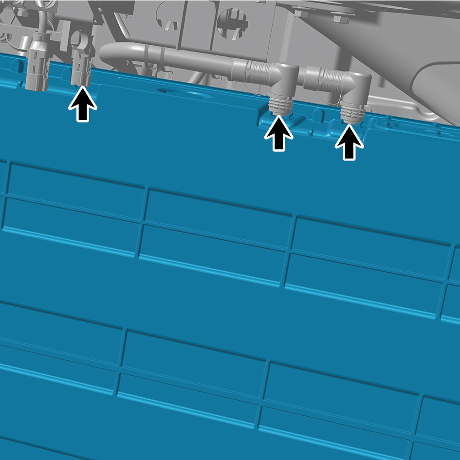
pack assembly 1 (CALB 161Ah).
24
Disconnect the 2 water pipes of the NCM-battery pack
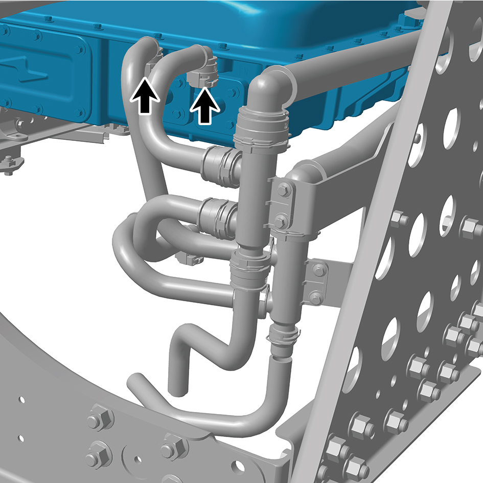
assembly 1 (CALB 161Ah).
caution
Use a clean container to receive the discharged
coolant.
25
Remove 1 fixing bolt of the ground harness.
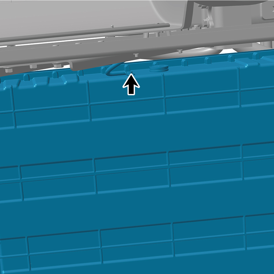
26
Jack the NCM-battery pack assembly 1 (CALB 161Ah).
27
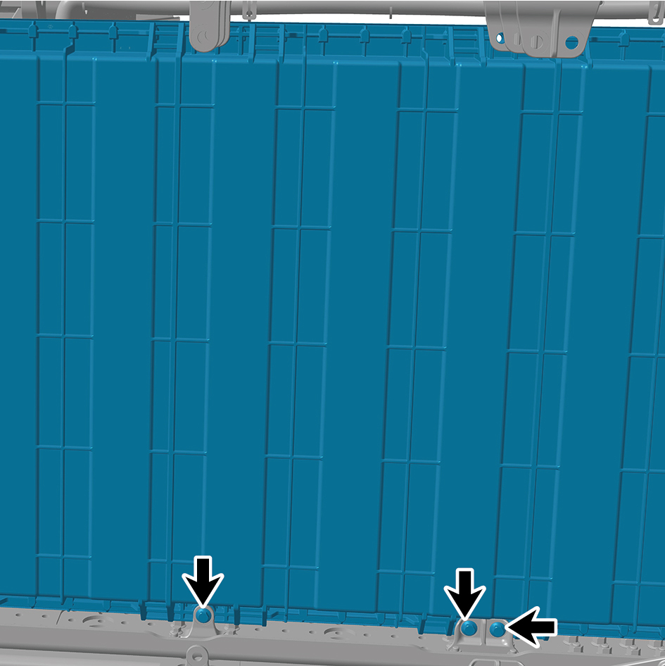
Remove the 7 fixing bolts and nuts of the NCM-battery
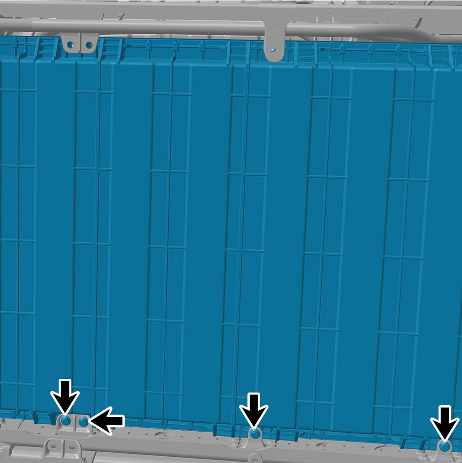
pack assembly 1 (CALB 161Ah) and detach the NCM-
battery pack assembly 1 (CALB 161Ah).
Installation Procedures
1
Use the high voltage battery lifting platform to support the
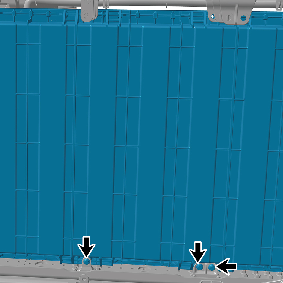
high voltage battery, and move the NCM-battery pack
assembly 1 (CALB 161Ah) to the installation position.
2
Jack the NCM-battery pack assembly 1 (CALB 161Ah).
3
Install the 7 fixing bolts and nuts of the NCM-battery pack
assembly 1 (CALB 161Ah).
Torque:(148 ft-lb +/- 7 ft-lb) ft-lb
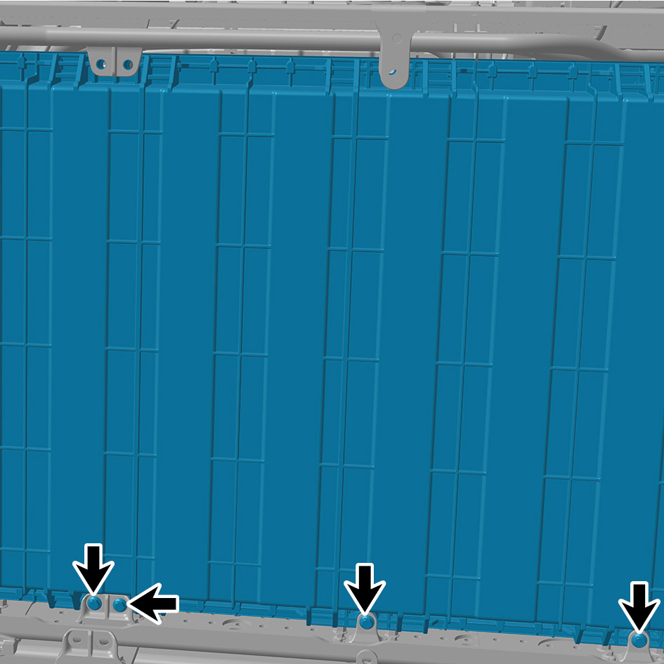
4
Install 1 fixing bolt of the ground harness.
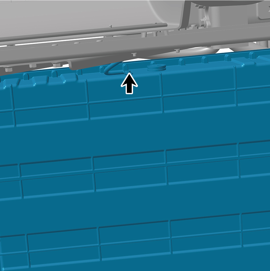
Torque: (18.5 ft-lb +/- 2 ft-lb) ft-lb
5
Connect the 2 water pipes of the NCM-battery pack
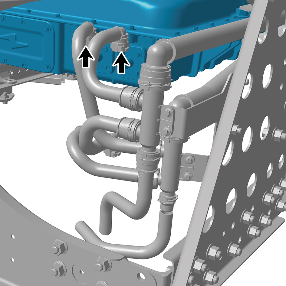
assembly 1 (CALB 161Ah).
6
Connect the 3 harness connectors of the NCM-battery
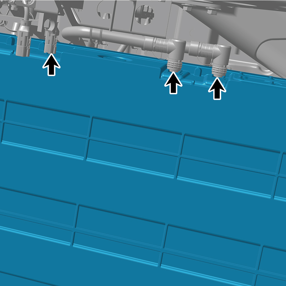
pack assembly 1 (CALB 161Ah).
caution
The harness is firmly connected following the
principal of "insert until a click is heard for
confirmation".
7
Install the NCM-battery pack assembly 2 (CALB 161Ah).
8
Install the outer battery mount (NCM).
9
Install the outer battery bracket double hole (NCM).
10
Install the bottom middle inclined beam bracket 2.
11
Install the bottom rear left inclined beam.
12
Install the bottom middle cross beam.
13
Install the bottom middle inclined beam 1.
14
Install the bottom front left inclined beam.
15
Install the left skirt plate assembly.
16
Install the left side wall lower trim panel mounting frame
assembly.
17
Install the left side wall mounting bracket 2.
18
Install the left side wall mounting bracket 1.
19
Install the side wall upper mounting bracket assembly 2.
20
Install the left side wall lower trim panel assembly.
21
Fill coolant in the battery thermal management system.
22
Lower the rear end of the vehicle.
23
Lower the front end of the vehicle.
24
Perform power-on of the high voltage system.
25
Connect the battery negative cable.
26
Close the front flip cover plate.
27
Close the door.
4.3.5.2 Replacement of NCM-battery Pack Assembly 2 (CALB 161Ah).
Assembly 2 (CALB 161Ah).
Removal Procedures
1
Open the door.
2
Open the front flip cover plate.
3
Disconnect the battery negative cable.
4
Perform power-off of high voltage system.
5
Jack the front end of the vehicle.
6
Jack the rear end of the vehicle.
7
Drain coolant from battery thermal management system.
8
Remove the left side wall lower trim panel assembly.
9
Remove the side wall upper mounting bracket assembly
2.
10
Remove the left side wall mounting bracket 1.
11
Remove the left side wall mounting bracket 2.
12
Remove the left side wall lower trim panel mounting frame
assembly.
13
Remove the left skirt plate assembly.
14
Use the high voltage battery lifting platform to support the
high voltage battery.
15
Remove the bottom front left inclined beam.
16
Remove the bottom middle inclined beam 1.
17
Remove the bottom middle cross beam.
18
Remove the bottom rear left inclined beam.
19
Remove the bottom middle inclined beam bracket 2.
20
Remove the outer battery bracket double hole (NCM).
21
Remove the outer battery mount (NCM).
22
Disconnect the 3 harness connectors of the NCM-battery
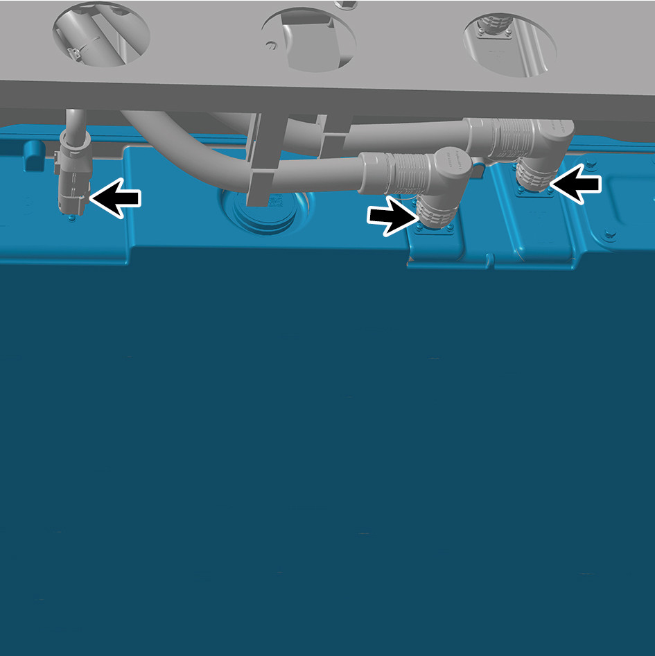
pack assembly 2 (CALB 161Ah).
23
Disconnect the 2 water pipes of the NCM-battery pack
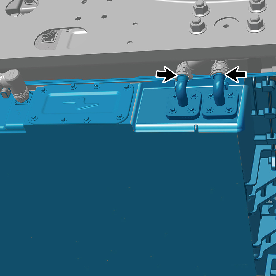
assembly 2 (CALB 161Ah).
caution
Use a clean container to receive the discharged
coolant.
24
Jack the NCM-battery pack assembly 2 (CALB 161Ah).
25
Remove 1 fixing bolt of the ground harness.
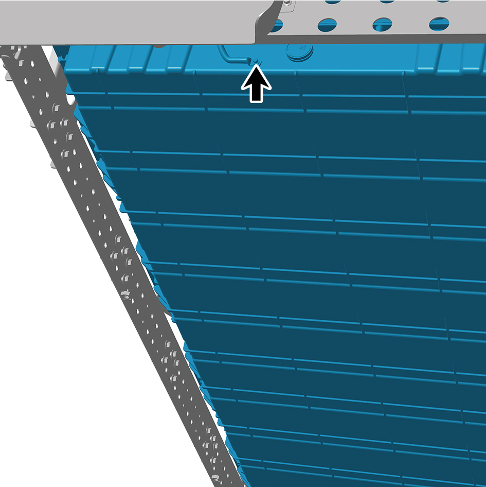
26
Remove the 7 fixing bolts and nuts of the NCM-battery
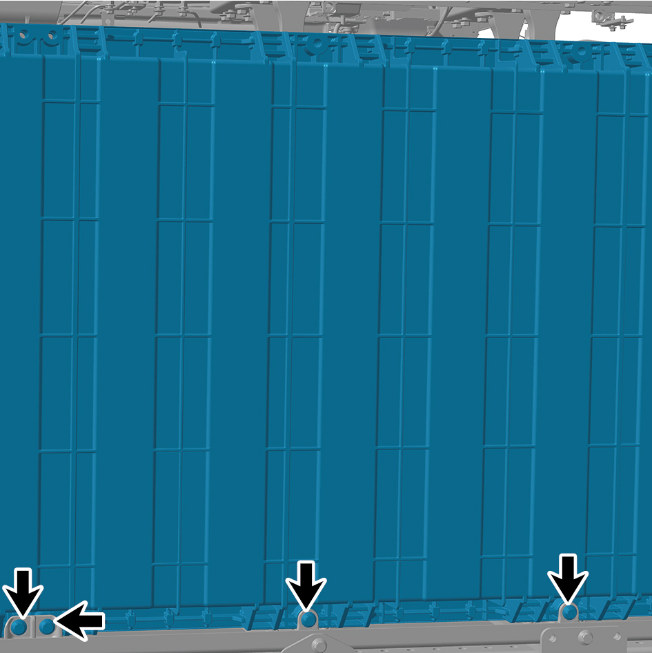
pack assembly 2 (CALB 161Ah) and detach the NCM-
battery pack assembly 2 (CALB 161Ah).
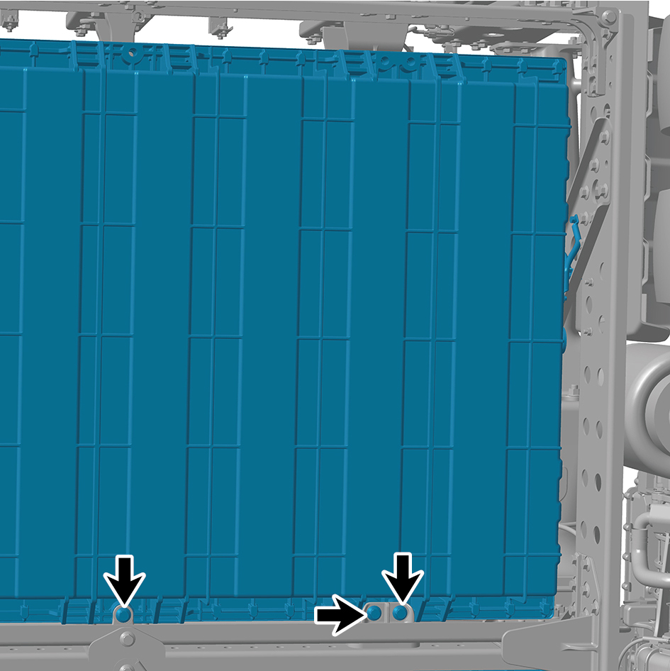
Installation Procedures
1
Use the high voltage battery lifting platform to support the
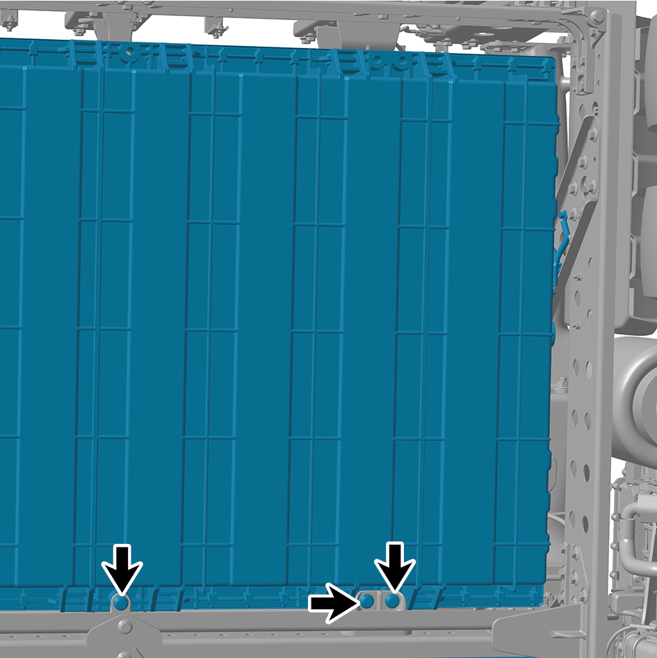
high voltage battery, and move the NCM-battery pack
assembly 2 (CALB 161Ah) to the installation position.
2
Jack the NCM-battery pack assembly 2 (CALB 161Ah).
3
Install the 7 fixing bolts and nuts of the NCM-battery pack
assembly 2 (CALB 161Ah).
Torque: (148 ft-lb +/- 7 ft-lb) ft-lb
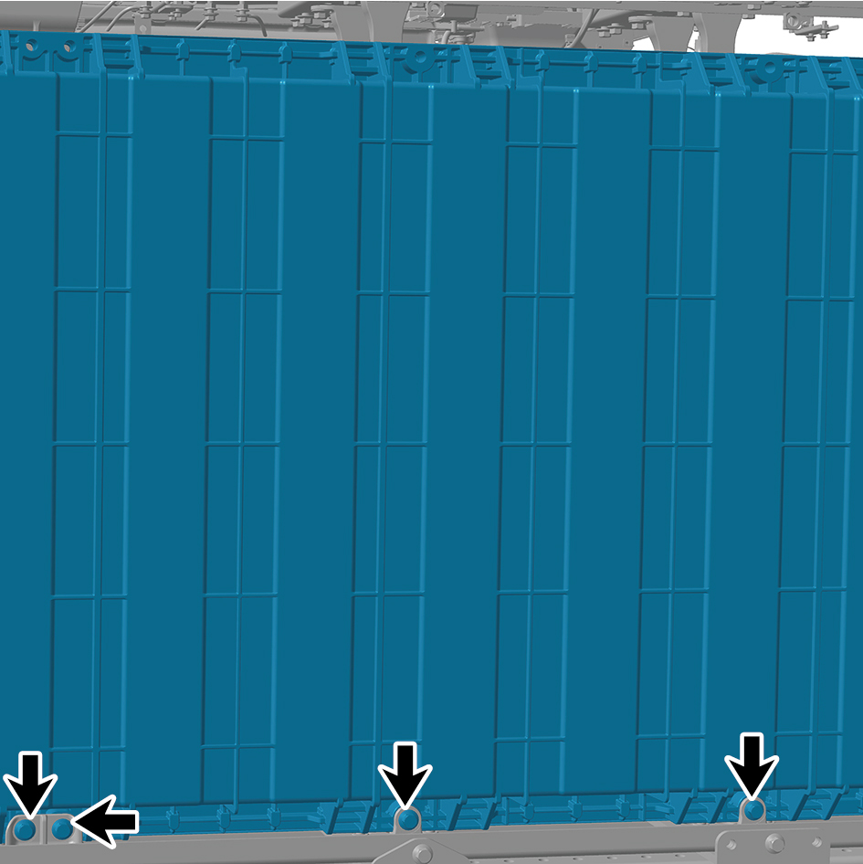
4
Install 1 fixing bolt of the ground harness.
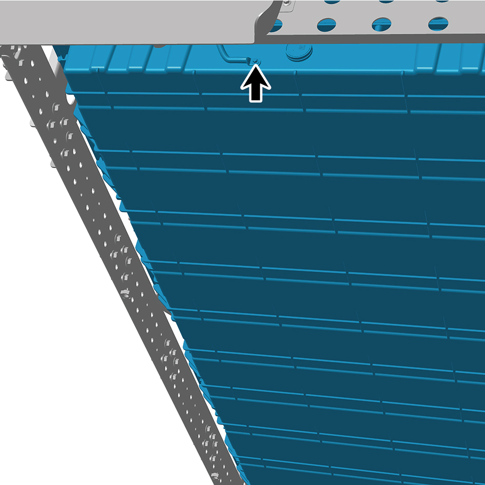
Torque:(18 ft-lb +/- 2 ft-lb) ft-lb
5
Connect the 2 water pipes of the NCM-battery pack
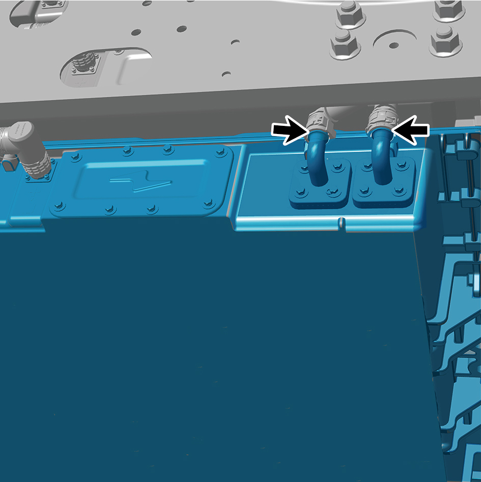
assembly 2 (CALB 161Ah).
6
Connect the 3 harness connectors of the NCM-battery
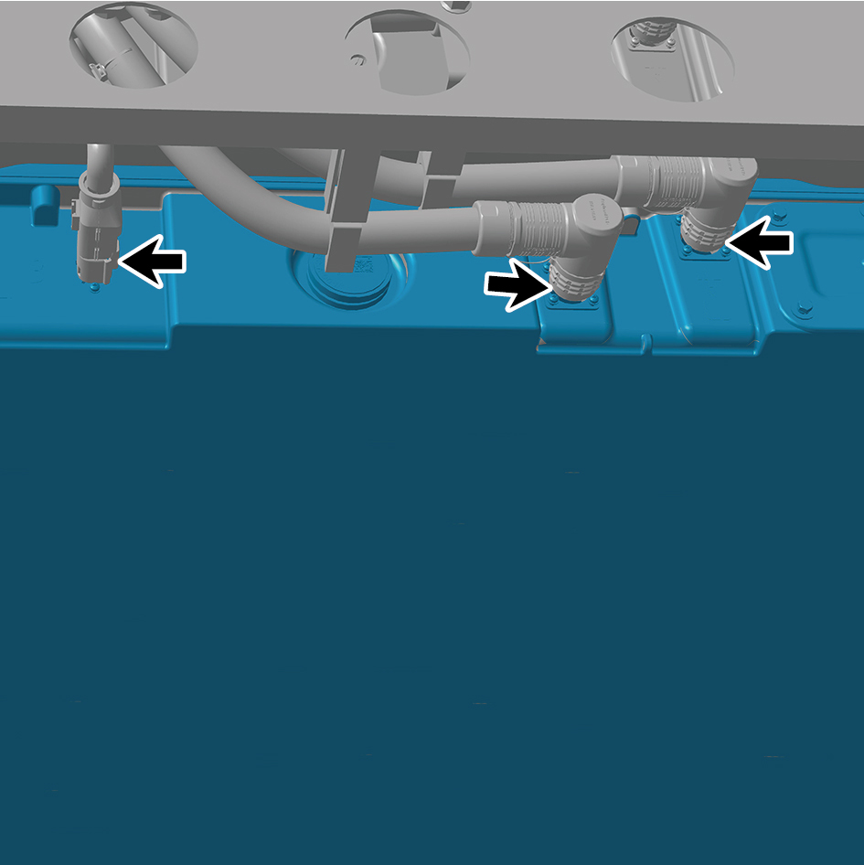
pack assembly 2 (CALB 161Ah).
caution
The harness is firmly connected following the
principal of "insert until a click is heard for
confirmation".
7
Install the outer battery mount (NCM).
8
Install the outer battery bracket double hole (NCM).
9
Install the bottom middle inclined beam bracket 2.
10
Install the bottom rear left inclined beam.
11
Install the bottom middle cross beam.
12
Install the bottom middle inclined beam 1.
13
Install the bottom front left inclined beam.
14
Install the left skirt plate assembly.
15
Install the left side wall lower trim panel mounting frame
assembly.
16
Install the left side wall mounting bracket 2.
17
Install the left side wall mounting bracket 1.
18
Install the side wall upper mounting bracket assembly 2.
19
Install the left side wall lower trim panel assembly.
20
Fill coolant in the battery thermal management system.
21
Lower the rear end of the vehicle.
22
Lower the front end of the vehicle.
23
Perform power-on of the high voltage system.
24
Connect the battery negative cable.
25
Close the front flip cover plate.
26
Close the door.
4.3.5.3 Replacement of NCM-Battery Pack Assembly 3 (CALB 161Ah).
Assembly 3 (CALB 161Ah).
Removal Procedures
1
Open the door.
2
Open the front flip cover plate.
3
Disconnect the battery negative cable.
4
Perform power-off of high voltage system.
5
Jack the front end of the vehicle.
6
Jack the rear end of the vehicle.
7
Drain coolant from battery thermal management system.
8
Remove the lamp (upper).
9
Remove the lamp (lower).
10
Remove the boarding step body assembly.
11
Remove the right side wall lower trim panel assembly.
12
Remove the right skirt plate assembly.
13
Use the high voltage battery lifting platform to support the
high voltage battery.
14
Remove the bottom front right inclined beam.
15
Remove the bottom middle inclined beam 1.
16
Remove the bottom middle cross beam.
17
Remove the bottom rear left inclined beam.
18
Remove the bottom middle inclined beam bracket 2.
19
Remove the outer battery bracket double hole (NCM).
20
Remove the outer battery mount (NCM).
21
Remove the NCM-battery pack assembly 4 (CALB
161Ah).
23
Disconnect the 3 harness connectors of the NCM-battery
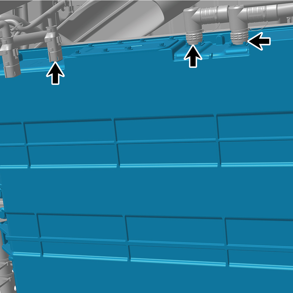
pack assembly 3 (CALB 161Ah).
24
Disconnect the 2 water pipes of the NCM-battery pack
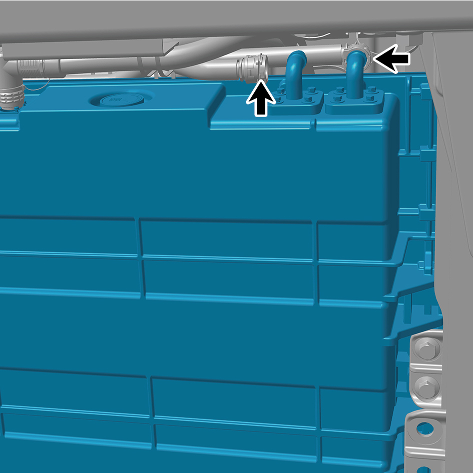
assembly 3 (CALB 161Ah).
caution
Use a clean container to receive the discharged
coolant.
25
Remove 1 fixing bolt of the ground harness.
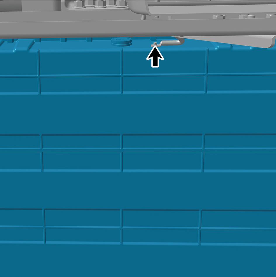
26
Jack the NCM-battery pack assembly 3 (CALB 161Ah).
27
Remove the 7 fixing bolts and nuts of the NCM-battery
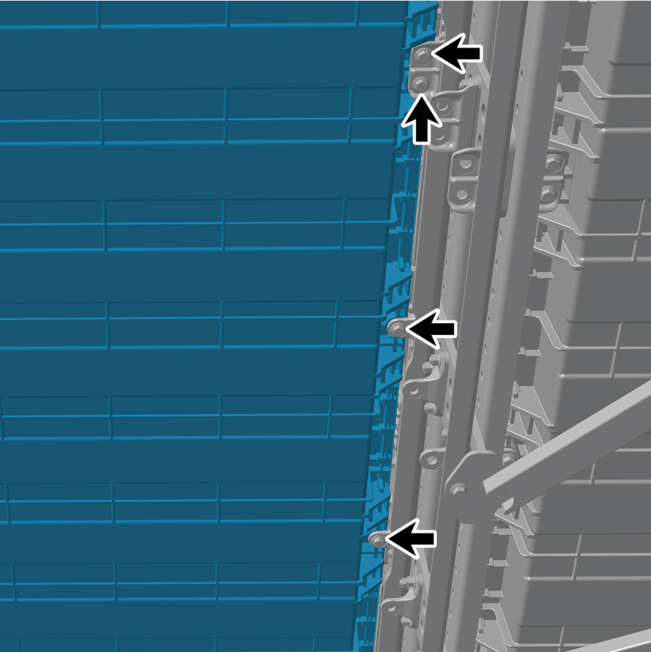
pack assembly 3 (CALB 161Ah) and detach the NCM-
battery pack assembly 3 (CALB 161Ah).
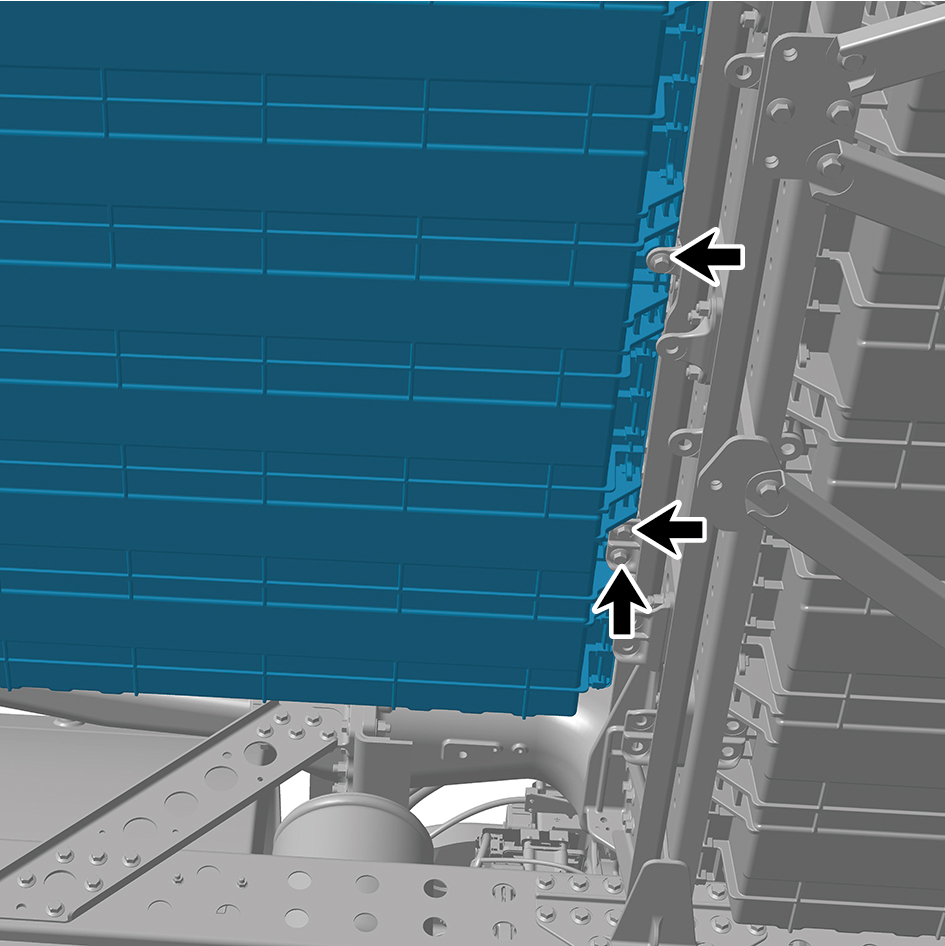
Installation Procedures
1
Use the high voltage battery lifting platform to support the
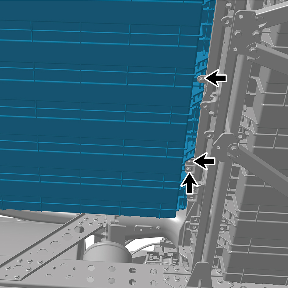
high voltage battery, and move the NCM-battery pack
assembly 3 (CALB 161Ah) to the installation position.
2
Jack the NCM-battery pack assembly 3 (CALB 161Ah).
3
Install the 7 fixing bolts and nuts of the NCM-battery pack
assembly 3 (CALB 161Ah).
Torque: (148 ft-lb +/- 7 ft-lb) ft-lb
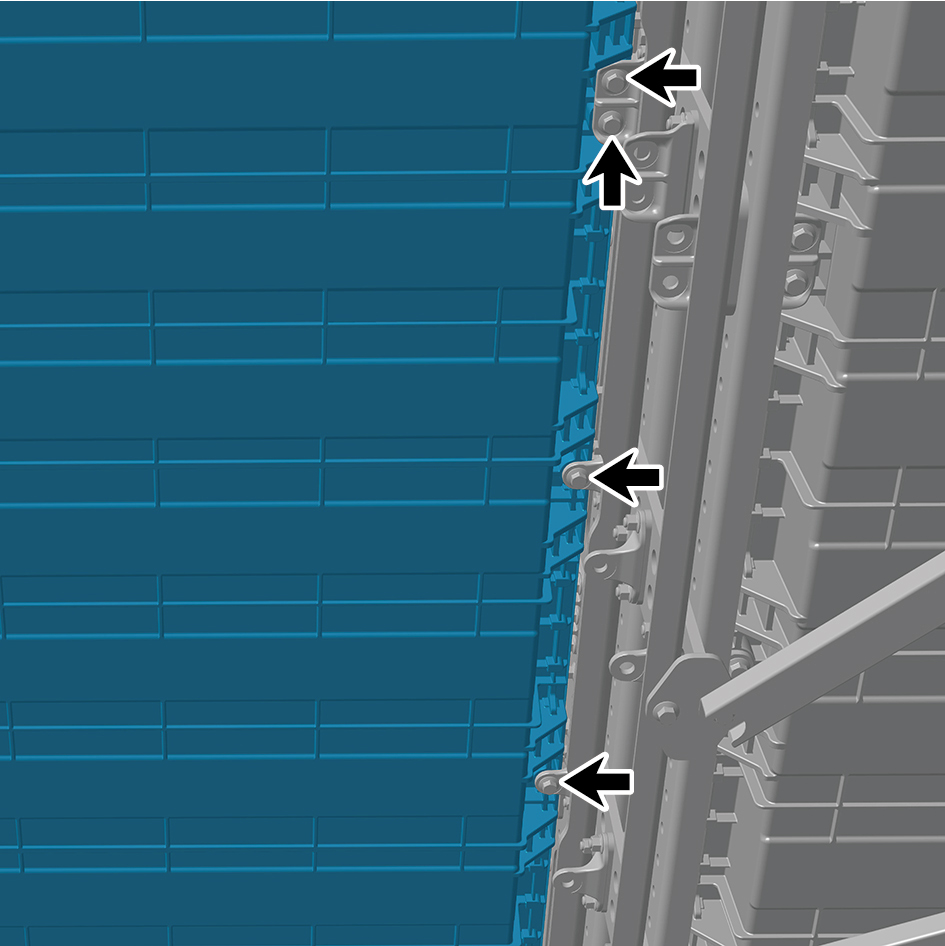
4
Install 1 fixing bolt of the ground harness.
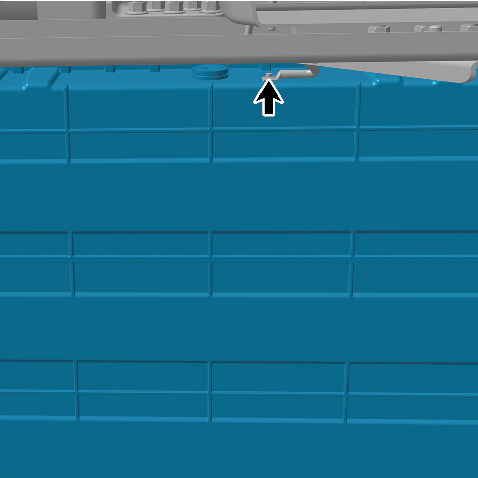
Torque: (18 ft-lb +/- 2 ft-lb) ft-lb
5
Connect the 2 water pipes of the NCM-battery pack
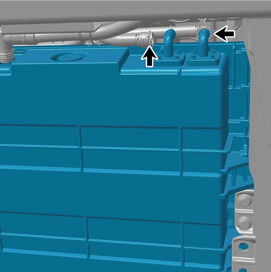
assembly 3 (CALB 161Ah).
6
Connect the 3 harness connectors of the NCM-battery
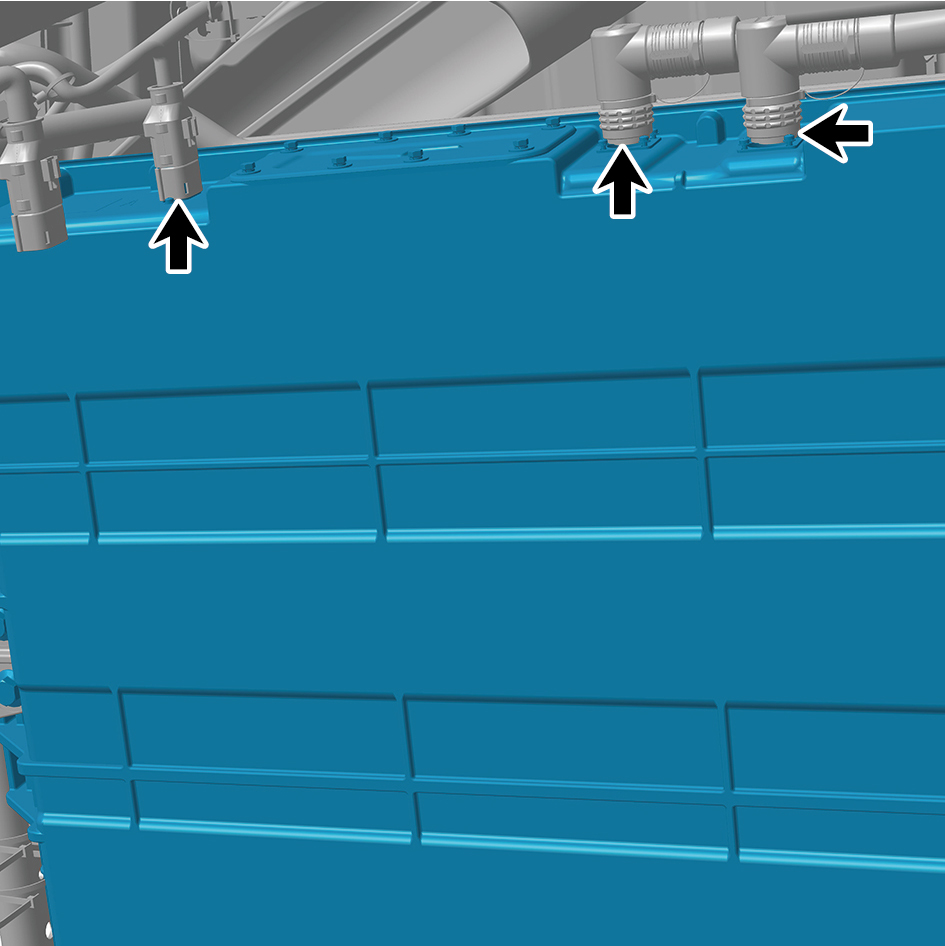
pack assembly 3 (CALB 161Ah).
caution
The harness is firmly connected following the
principal of "insert until a click is heard for
confirmation".
8
Install the NCM-battery pack assembly 4 (CALB 161Ah).
9
Install the outer battery mount (NCM).
10
Install the outer battery bracket double hole (NCM).
11
Install the bottom middle inclined beam bracket 2.
12
Install the bottom rear left inclined beam.
13
Install the bottom middle cross beam.
14
Install the bottom middle inclined beam 1.
15
Install the bottom front right inclined beam.
16
Install the right skirt plate assembly.
17
Attach the right side wall lower trim panel assembly.
18
Install the boarding step body assembly.
19
Install the lamp (lower).
20
Install the lamp (upper).
21
Fill coolant in the battery thermal management system.
22
Lower the rear end of the vehicle.
23
Lower the front end of the vehicle.
24
Perform power-on of the high voltage system.
25
Connect the battery negative cable.
26
Close the front flip cover plate.
27
Close the door.
4.3.5.4 Replacement of NCM-battery Pack Assembly 4 (CALB 161Ah).
Assembly 4 (CALB 161Ah).
Removal Procedures
1
Open the door.
2
Open the front flip cover plate.
3
Disconnect the battery negative cable.
4
Perform power-off of high voltage system.
5
Jack the front end of the vehicle.
6
Jack the rear end of the vehicle.
7
Drain coolant from battery thermal management system.
8
Remove the lamp (upper).
9
Remove the lamp (lower).
10
Remove the boarding step body assembly.
11
Remove the right side wall lower trim panel assembly.
12
Remove the right skirt plate assembly.
13
Use the high voltage battery lifting platform to support the
high voltage battery.
14
Remove the bottom front right inclined beam.
15
Remove the bottom middle inclined beam 1.
16
Remove the bottom middle cross beam.
17
Remove the bottom rear left inclined beam.
18
Remove the bottom middle inclined beam bracket 2.
19
Remove the outer battery bracket double hole (NCM).
20
Remove the outer battery mount (NCM).
21
Disconnect the 3 harness connectors of the NCM-battery
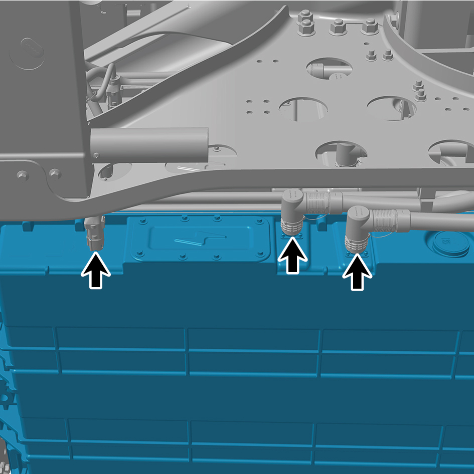
pack assembly 4 (CALB 161Ah).
22
Disconnect the 2 water pipes of the NCM-battery pack
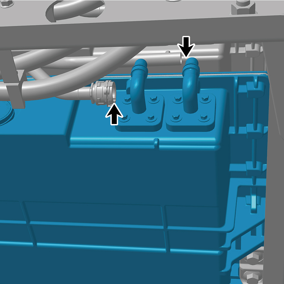
assembly 4 (CALB 161Ah).
caution
Use a clean container to receive the discharged
coolant.
23
Remove 1 fixing bolt of the ground harness.
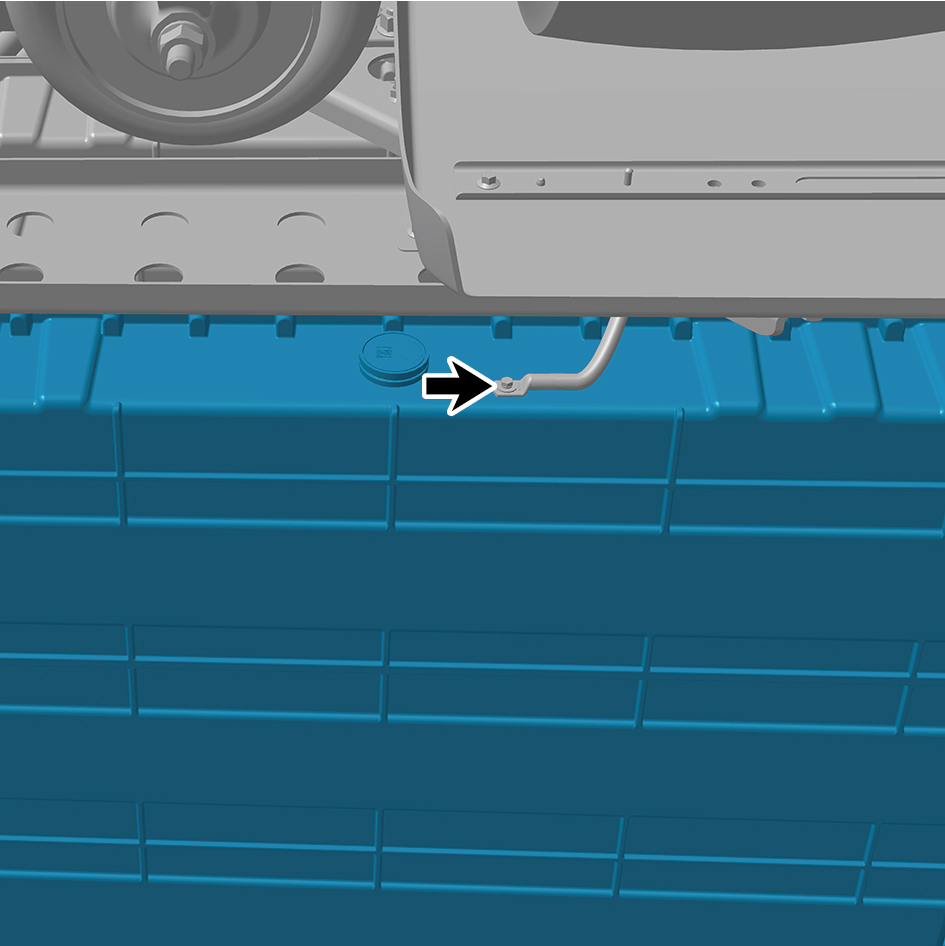
24
Jack the NCM-battery pack assembly 4 (CALB 161Ah).
25
Remove the 7 fixing bolts and nuts of the NCM-battery
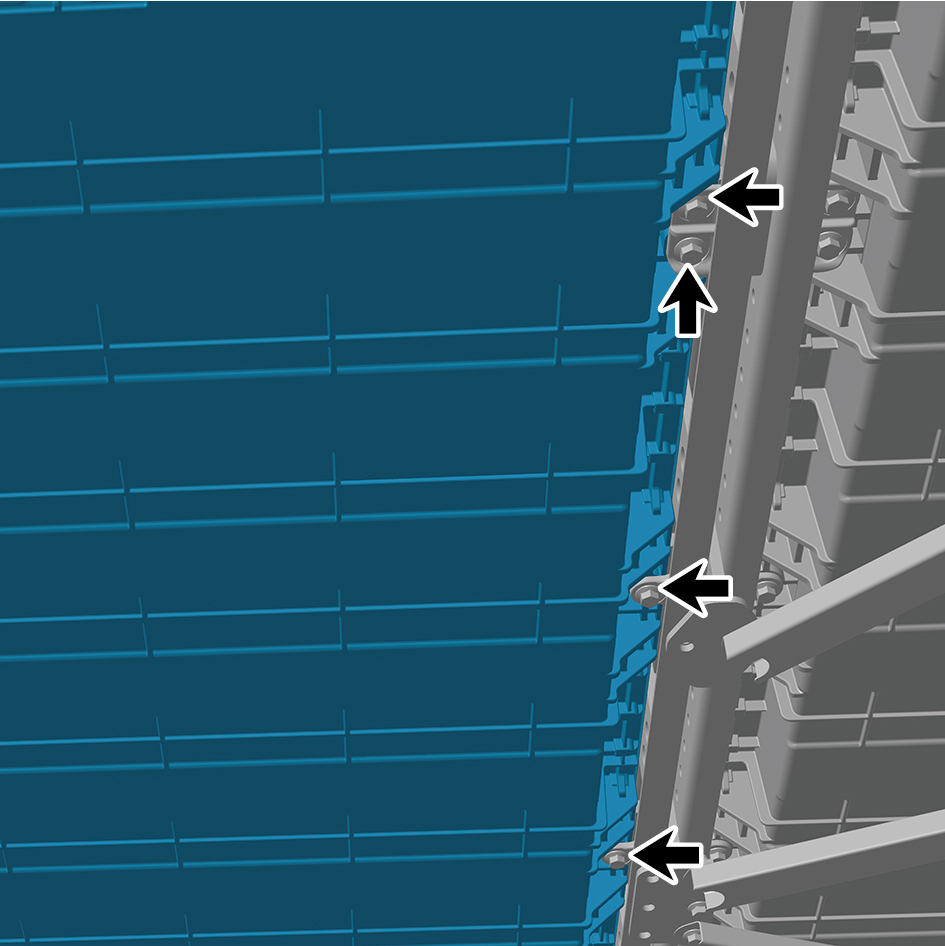
pack assembly 4 (CALB 161Ah) and detach the NCM-
battery pack assembly 4 (CALB 161Ah).
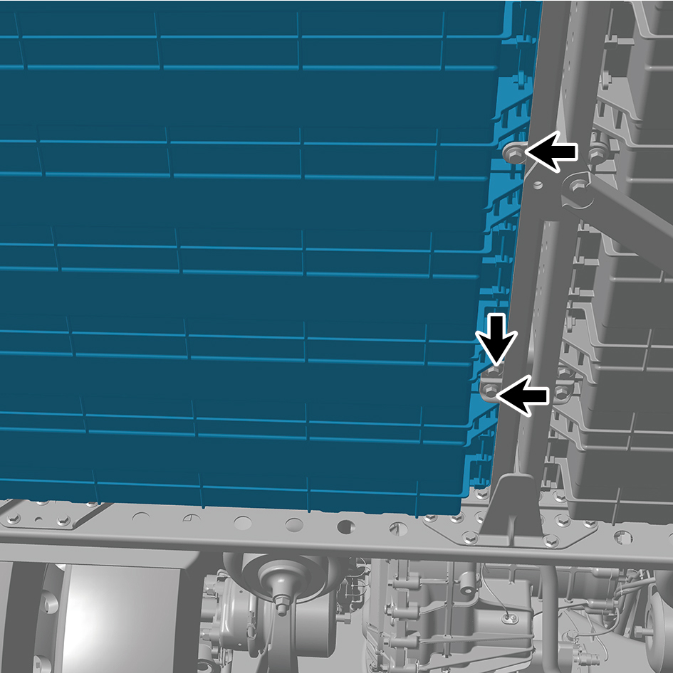
Installation Procedures
1
Use the high voltage battery lifting platform to support the
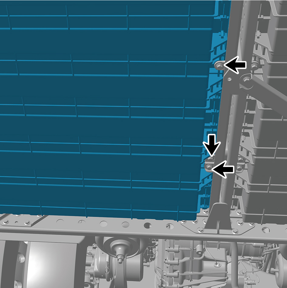
high voltage battery, and move the NCM-battery pack
assembly 4 (CALB 161Ah) to the installation position.
2
Jack the NCM-battery pack assembly 4 (CALB 161Ah).
3
Install the 7 fixing bolts and nuts of the NCM-battery pack
assembly 4 (CALB 161Ah).
Torque:(148 ft-lb +/- 7 ft-lb) ft-lb
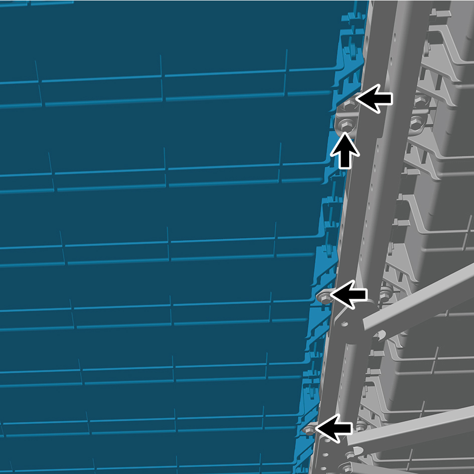
4
Install 1 fixing bolt of the ground harness.
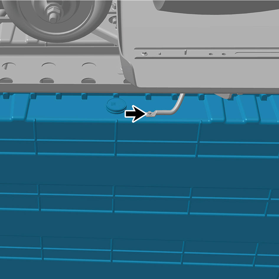
Torque: (18 ft-lb +/- 2 ft-lb) ft-lb
5
Connect the 2 water pipes of the NCM-battery pack
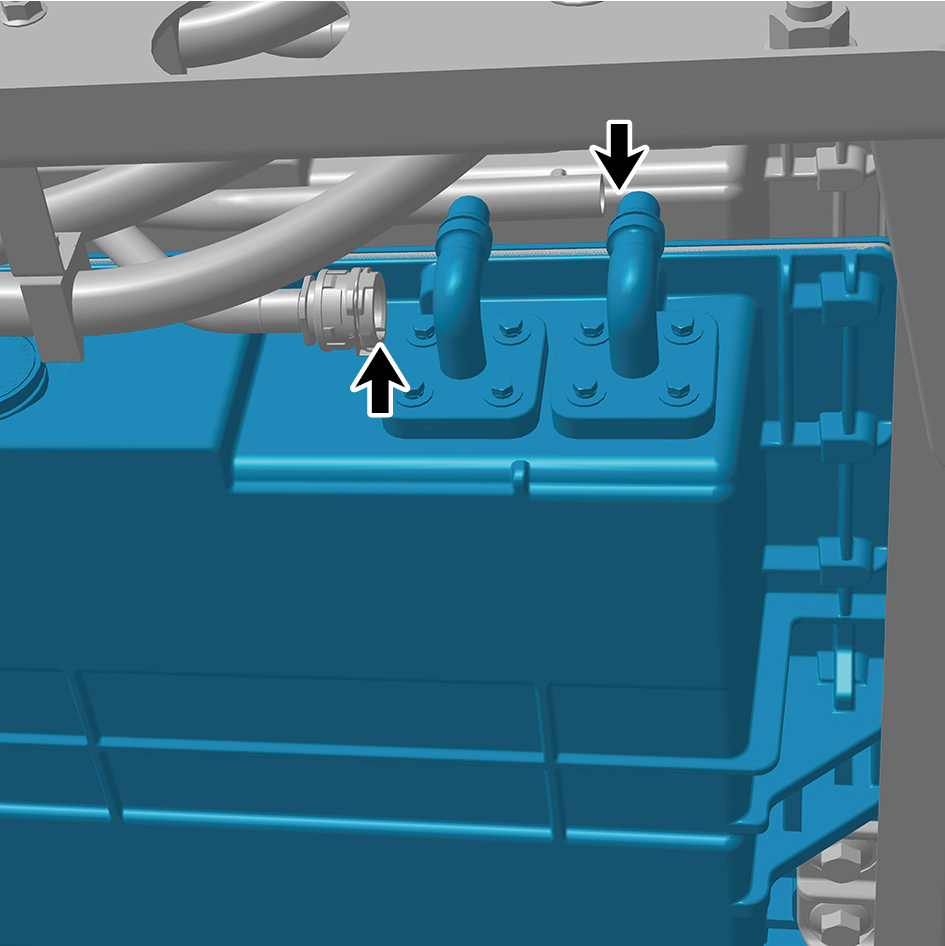
assembly 4 (CALB 161Ah).
6
Connect the 3 harness connectors of the NCM-battery
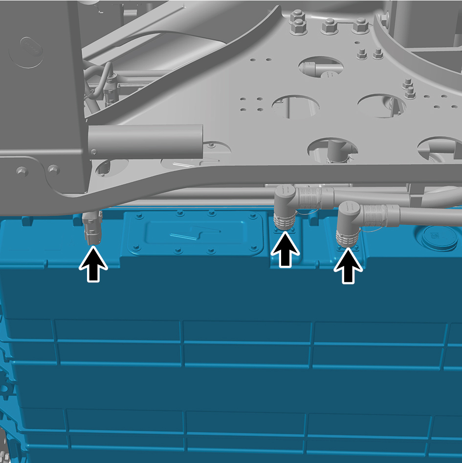
pack assembly 4 (CALB 161Ah).
caution
The harness is firmly connected following the
principal of "insert until a click is heard for
confirmation".
7
Install the outer battery mount (NCM).
8
Install the outer battery bracket double hole (NCM).
9
Install the bottom middle inclined beam bracket 2.
10
Install the bottom rear left inclined beam.
11
Install the bottom middle cross beam.
12
Install the bottom middle inclined beam 1.
13
Install the bottom front right inclined beam.
14
Install the right skirt plate assembly.
15
Attach the right side wall lower trim panel assembly.
16
Install the boarding step body assembly.
17
Install the lamp (lower).
18
Install the lamp (upper).
19
Fill coolant in the battery thermal management system.
20
Lower the rear end of the vehicle.
21
Lower the front end of the vehicle.
22
Perform power-on of the high voltage system.
23
Connect the battery negative cable.
24
Close the front flip cover plate.
25
Close the door.