Install entry stepsInstall side trim strips and upper bracketsInstall front wheel mud guardsSide skirt installation (pre-assembly)High-voltage cable — battery pack connection
Steps, Side Trim, Mud Guards, High-voltage Cables Pre-assembly Station · Illustrated version of 5 operations | Compiled from the original process card for training and display
Install entry steps
Page 3 / Detailed steps are on page 1 | Operation steps
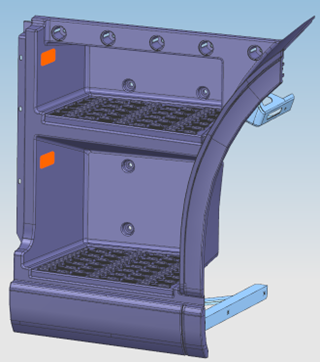
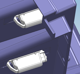
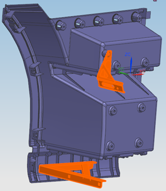
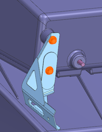
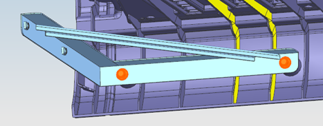
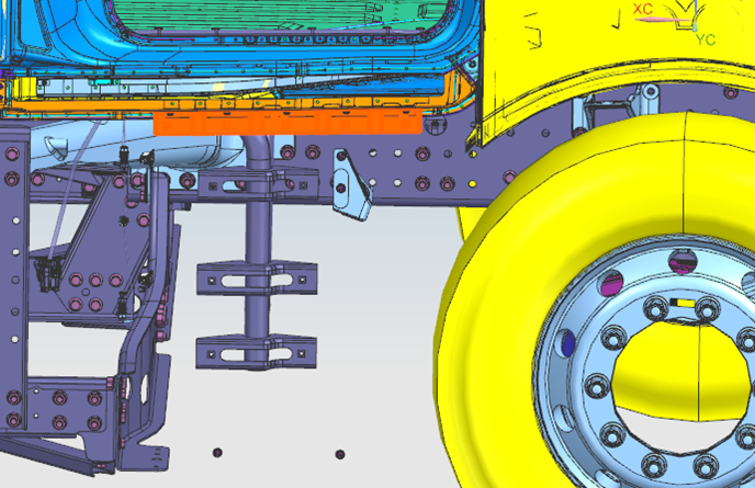
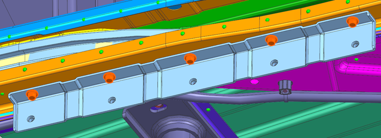
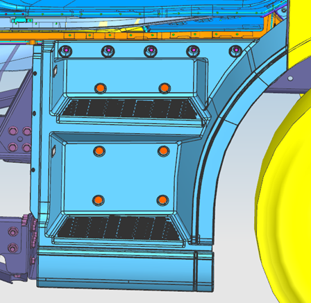
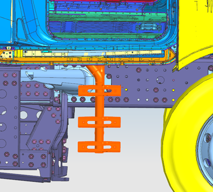
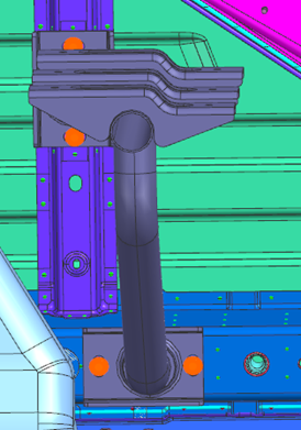
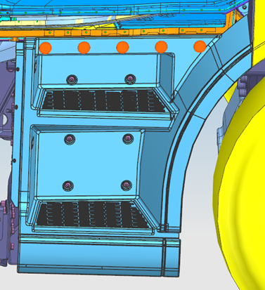
Step 10: Install the courtesy lamp at the position shown. Step 20: Snap the courtesy lamp onto the vertical face of the step, noting the lamp mounting direction. Step 30: Install the front wheel-arch upper and lower mounting brackets; tightening torque 20-26 N·m. Step 40: Install the step pipe beam to the underside of the cab at 4 fixing points, aligning the fixing holes with the fasteners as much as possible during installation. Step 50: Install the upper entry step bracket with 5 fixing points. Step 60: Install the pre-assembled entry step at the position shown without tightening the bolts first; fine-adjust the step so that it aligns with the fender character lines with even gaps, then tighten the fixing bolts; check the alignment with the fender once more. Step 70: Install the 5 plugs on the upper edge of the step. Step 80: Connect the courtesy lamp harness connector to the floor harness, and secure the 2 connectors and the clip between them to the step.
Parts required
Entry step pipe beam ×1
Entry step bracket ×1
Upper wheel-arch connection bracket ×1
Lower wheel-arch connection bracket ×1
Entry step plug ×5
Entry step body assembly ×1
Courtesy lamp ×2
Hex flange bolt (thick shank) ×14
Hexalobular socket pan-head screw ×6
Tools / fixtures
Torque wrench
✓ Quality inspection points
Tightening torque: 23±3 N·m; Wheel-arch bracket torque: 20-26 N·m; The step must be aligned with the fender character lines with even gaps
Reference illustrations (click to enlarge)
Install side trim strips and upper brackets
Page 2 | Operation steps
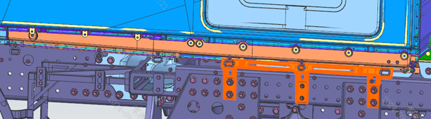
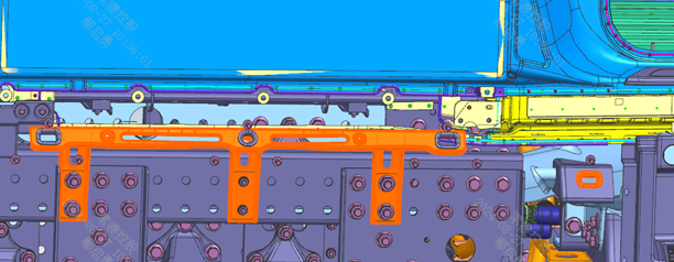
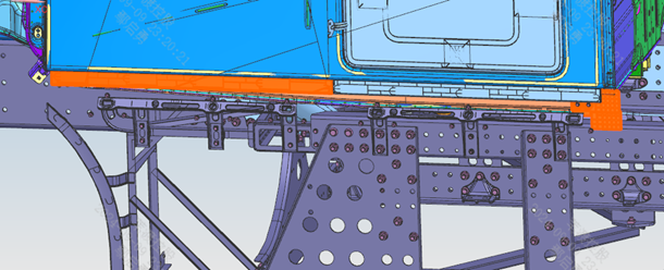
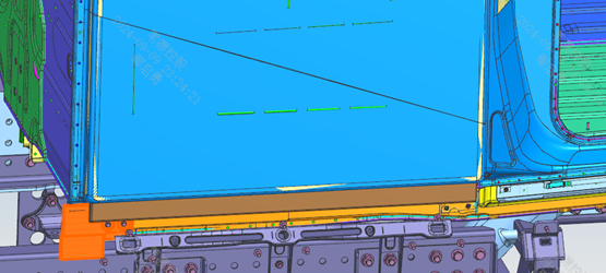
Step 10: Install the side upper mounting brackets as shown. Step 20: Snap rubber sleeve 1 and rubber sleeve 2 into the bracket holes, fully seated so they do not easily come off. Step 30: Inspect the appearance of the trim strips and confirm there is no deformation, surface damage, scratches or oil contamination before installation. Step 40: Note during installation: the edge closer to the clips is the lower edge of the trim strip. Step 50: Install the trim strips — 2 pieces on the left side and 1 piece on the right. Step 60: Align the locating holes with the body in the positive Y direction; first tap the plastic clips at the main locating points into the sheet metal, then tap the remaining plastic clips in all at once. Step 70: After assembly, check for any missing or loose parts.
Parts required
Side trim strip assembly 1/2/3 ×1 each; Side upper mounting bracket assembly 1/3 ×1 each; Rubber sleeve 1 ×5; Rubber sleeve 2 ×2; Left side baffle assembly ×1; Right side baffle assembly ×1; Hex flange nut ×12; Hex flange bolt (thick shank) ×4
Tools / fixtures
Torque wrench
✓ Quality inspection points
Tightening torque: 23±3 N·m; Check for any missing or loose parts
Reference illustrations (click to enlarge)
Install front wheel mud guards
Page 3 | Operation steps
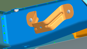
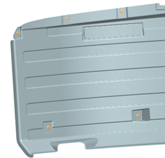
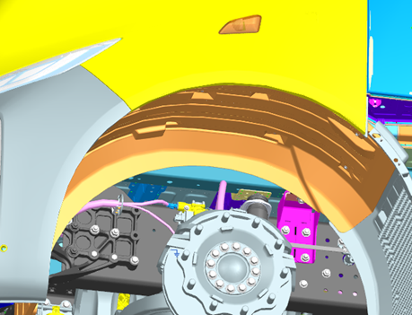
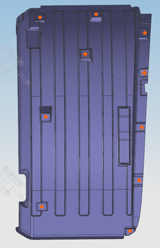
Step 10: Install the left front front wheel-arch bracket as shown. Step 20: Install the 'left front front wheel-arch body' with a total of 16 fixing points. Step 30: Install the right front wheel front mud guard as shown. Step 40: Install the right front wheel rear mud guard as shown. Step 50: Align the fixing holes first, then screw in the fixing bolts; finally, adjust the mud guards smooth before tightening all fixing bolts.
Parts required
Left front front wheel-arch bracket ×1
Left front rear wheel-arch assembly ×1
Right front rear wheel-arch assembly ×1
Left front front wheel-arch body ×1
Right front front wheel-arch body ×1
Wheel-arch plug ×2
Hex flange bolt (thick shank) ×45
✓ Quality inspection points
Visual inspection: the mud guards must be adjusted smooth before tightening
Reference illustrations (click to enlarge)
Side skirt installation (pre-assembly)
Page 4 / Detailed steps are on page 1 | Operation steps
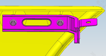
Step 10: Pre-assemble the left side skirt as shown; during installation, note that the side marker lamp locating features must correspond to the holes. Step 20: Pre-assemble the right side skirt as shown; likewise, ensure the side marker lamp locating features correspond to the holes during installation.
Parts required
Side marker combination lamp ×4
Left side skirt assembly ×1
Right side skirt assembly ×1
Upper skirt connection bracket ×10
Left rear wheel-arch connection bracket ×1
Right rear wheel-arch connection bracket ×1
Left millimeter-wave radar ×1
Right millimeter-wave radar ×1
Rubber buffer pad ×4
Hex flange nut ×8
Hex flange bolt ×24
Tools / fixtures
Pointer-type torque wrench
✓ Quality inspection points
Tightening torque: 700±50 N·m
Reference illustrations (click to enlarge)
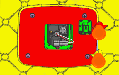
High-voltage cable — battery pack connection
Page 2 / The folder contains two nearly identical versions of the process card; the more complete version is presented here | Operation steps
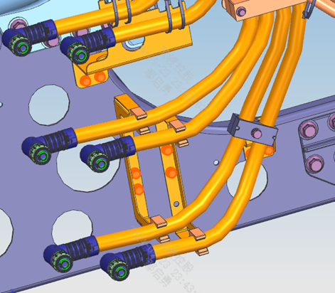
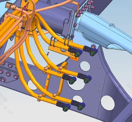
Important note: This connection must be performed only after the cables have been connected to the PDU; otherwise it may cause safety issues. Step 10: Prepare the cable fixing brackets and pipe clamps. Step 20: Plug the cables into the corresponding battery pack interfaces according to the markings; during plugging, ensure the cable ends are horizontal for ease of connection, and after plugging in, pull back slightly to confirm the connection is fully seated. Step 30: Install the pipe clamps and fixing brackets as shown, clipping the cables into the pipe clamps or securing them to the brackets with cable ties. Note: the high-voltage cables must not interfere with the sharp edges of metal parts or the fasteners.
Parts required
High-voltage harness fixing bracket assembly T14/T15/T18/T19/T20/T21 ×1-2 each; High-voltage harness fixing pipe clamp I/VII × several each; Hex flange nut ×15; Hex bolt with spring and flat washer assembly ×1; Flat-head cable tie 1 ×8
✓ Quality inspection points
Visual inspection: after plugging in, pull back to confirm the connection is fully seated; The cables must be kept clear of sharp metal edges
Reference illustrations (click to enlarge)
This page is compiled from the ZD112-1010 to ZD112-1090 process cards (Anhui Windrose Holdings Co., Ltd.) and is for workshop visual training only; official production shall follow the controlled process documents.