← Back to Contents
8 Chassis / 8.18 EBS Electronic Control Unit Execution Device | PDF pages 2193-2238
8.18 EBS Electronic Control Unit Execution Device
8.18 EBS Electronic Control Unit Execution Device
8.18 EBS Electronic Control Unit
Execution Device
8.18.1 Specifications
8.18.1.1 Fastener Specifications
Range Of Torque
Specifications
Fastener name
Foot Pounds of Torque (ft lbs)
The fixing bolt connecting the yaw
sensor assembly and the frame
18.5 +/- 2 (ft lbs)
M8
assembly
The fixing bolts connecting the EBS
8 +/- .75 (ft lbs)
M6
controller assembly to the EBS bracket
8.18.2 Decomposition Diagram
8.18.2.1 Decomposition Diagram
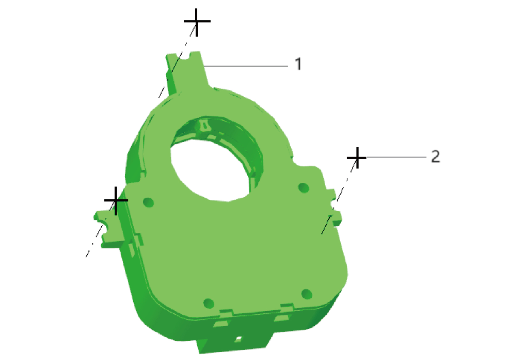
1.
2.
Angle Sensor Assy
Cross Recessed Pan Head Machine Screw
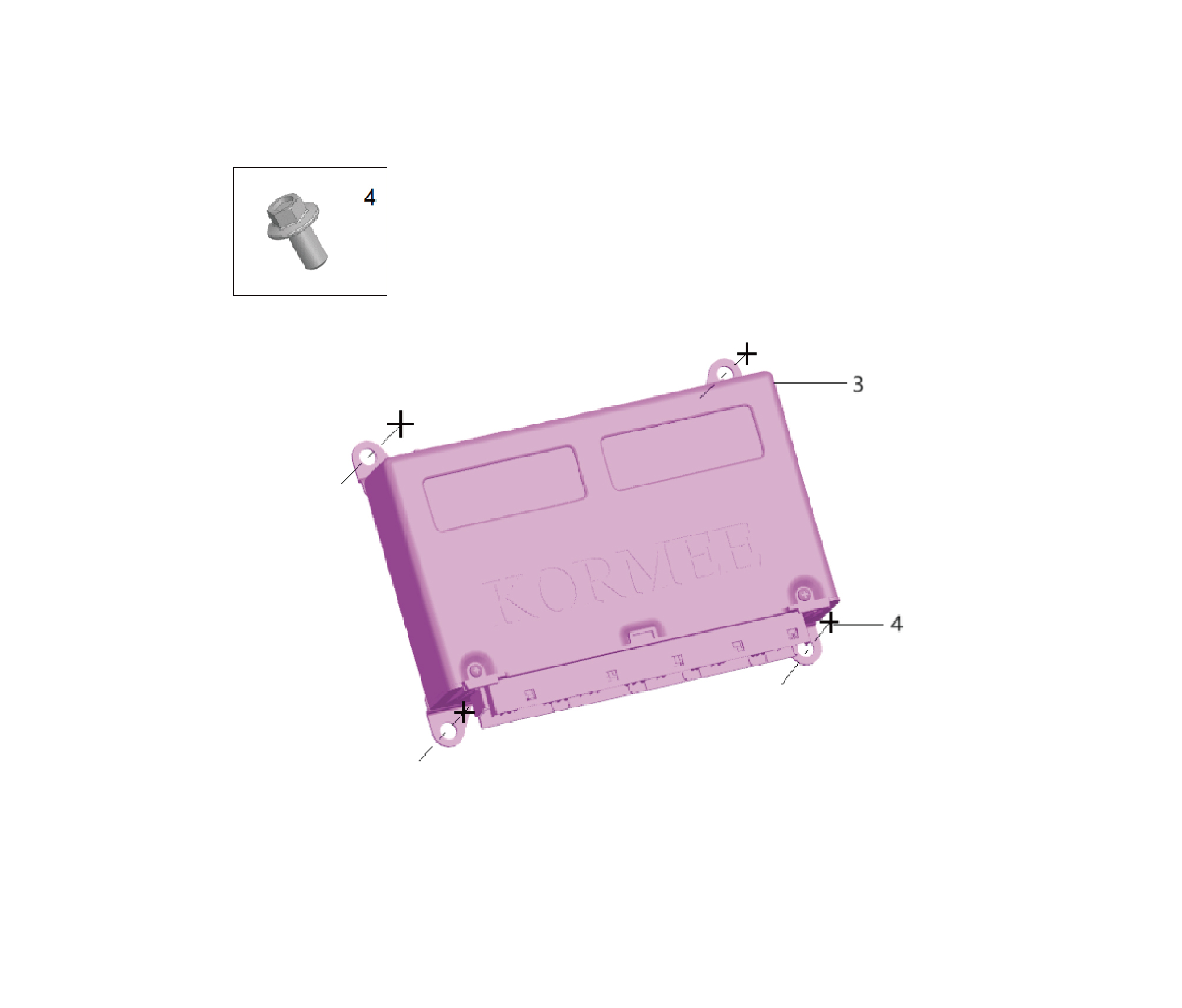
3.
4.
Hexagon Flange Bolt
Ebs Controller Assy
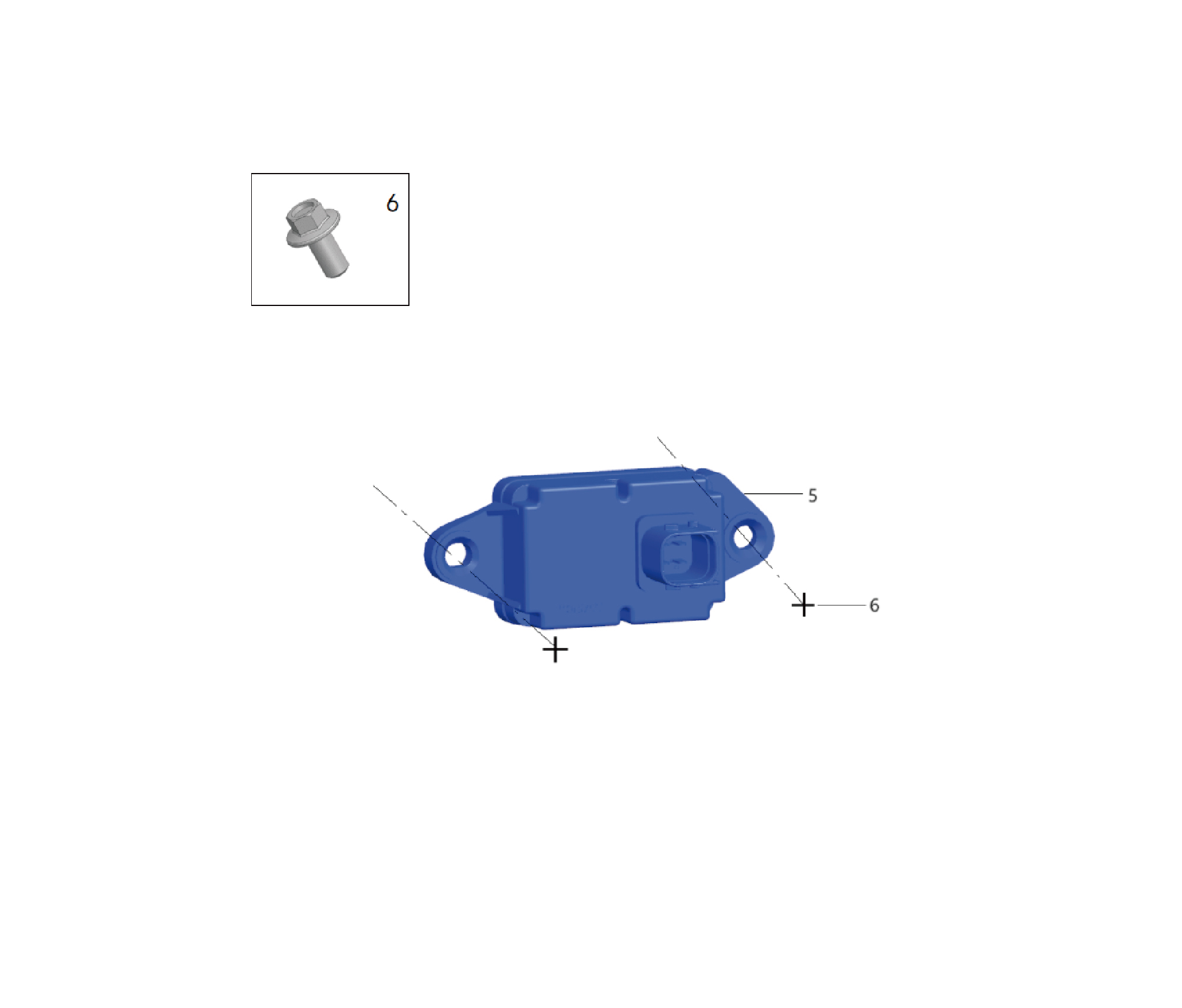
5.
6.
Hexagon Flange Bolt
Yaw Sensor Assy
8.18.3 System Schematic Diagram
8.18.3.1 Electrical Schematic Diagram
8.18.4 Diagnostic Information and Steps
8.18.4.1 Diagnostic Description
Before diagnosing the malfunction of the EBS electronic control unit execution device, it is important to understand and
familiarize oneself with the working principle of the EBS electronic control unit execution device before starting system diagnosis.
This will help determine the correct fault diagnosis steps when a malfunction occurs, and more importantly, it will help determine
the situation described by the customer belongs to normal operation. Any fault diagnosis of the EBS electronic control unit
execution device should start with routine inspection, guiding maintenance personnel to take the next logical step for fault
diagnosis. Understanding and correctly using the diagnostic process can shorten the diagnosis time and avoid misjudgment of
faulty parts.
8.18.4.2 Routine Inspection
• Check the after-sales installation devices that may affect the operation of the EBS electronic control unit execution device
system, ensuring that these devices cannot affect the operation of the EBS electronic control unit execution device system.
• Check system components that are easily accessible or visible to ensure that there is no obvious damage or potential
malfunction.
8.18.4.3 Fault Symptom Table
Symptom
Suspected Faulty Project
Measures
1.Wheel speed sensor installation error
Reinstall the wheel speed sensor and
adjust the gap between the wheel speed
2.The gap between the wheel speed
sensor and the signal board. Replace
sensor and the signal panel is too large
the wheel speed sensor or signal board
or too small, or foreign objects are
if necessary.
blocking it
Refer to Front Axle Left Wheel ABS
Sensor Fault.Front Axle Right Wheel
The EBS function is always working or
3.Wheel speed sensor malfunction
ABS Sensor Fault.Rear Axle Left Wheel
not working at any time
ABS Sensor Fault.Rear Axle Right
Wheel ABS Sensor Fault
Refer to Front Axle Left Wheel ABS
4.ABS solenoid valve malfunction
Solenoid Valve Fault.Front Axle Right
Wheel ABS Solenoid Valve Fault
Refer to Replacement Of EBS
5.EBS module malfunction
Controller Assembly
8.18.4.4 DTC Confirmation
1. Connect the diagnostic tool to the diagnostic interface, read and record the DTC, and then clear the DTC.
2. Run the vehicle again.
3. Read the fault code of the control system again to confirm if there is any fault code output from the system.
– Yes:Diagnose based on the output fault code.
– No:Perform intermittent fault check, refer to Inspection Of Intermittent Faults
8.18.4.5 List Of Diagnostic Trouble Codes (DTC)
EBS
Fault Description
Exclusion Method
Fault Code
The voltage of the ECU is too high
C330203
Refer to EBS Power Fault
The controller (ECU) voltage is too low
C330204
Fault Description
Exclusion Method
Fault Code
Valve power failure
C35020D
C3F0205
Vehicle CAN communication failure
Refer to EBS Communication Fault
The ESC CAN communication is faulty
B030205
C36020C
EEPROM fault
Refer to EBS Internal Fault
P210305
The DBR is disconnected
P2B0305
ESC not detected
The EPM CAN communication of axle 1
Refer to EBS Private CAN
B010205
and axle 2 is faulty
Communication Fault
Refer to Brake Signal Generator Fault
P220305
Foot valve failure
P340305
Trailer valve failure
Refer to Trailer Control Valve Fault
The yaw rate sensor is faulty
P390305
Refer to Yaw Rate Sensor Fault
The steering Angle sensor is faulty
Refer to Steering Angle Sensor Fault
P3A0305
The gap between the left front sensor
P150301
and the gear ring is too large
Refer to Front Axle Left Wheel ABS
P150306
Short-circuited left front sensor
Sensor Fault
P150305
Left front sensor disconnected
Left front ring missing teeth, deflection
P15030B
The gap between the right front sensor
P160301
and the gear ring is too large
Refer to Front Axle Right Wheel ABS
Right front sensor short-circuited
P160306
Sensor Fault
Right front sensor disconnected
P160305
Right front ring missing teeth, deflection
P16030B
The gap between the left rear/left
second sensor and the gear ring is too
P170301
large
The left rear/left second sensor is short-
P170306
Refer to Rear Axle Left Wheel ABS
circuited
Sensor Fault
The left rear/left second sensor is
P170305
disconnected
Missing teeth and deflection of left rear/
P17030B
left second ring
The gap between the right rear/right
second sensor and the gear ring is too
P180301
large
The right rear/right second sensor is
P180306
Refer to Rear Axle Right Wheel ABS
short-circuited
Sensor Fault
The right rear/right second sensor is
P180305
disconnected
Missing teeth and deflection of right
P18030B
rear/right second ring
Fault Description
Exclusion Method
Fault Code
P1D0306
Left front solenoid valve short circuit
Refer to Front Axle Left Wheel ABS
Solenoid Valve Fault
P1D0305
Left front solenoid valve disconnected
Right front solenoid valve short circuit
P1E0306
Refer to Front Axle Right Wheel ABS
Solenoid Valve Fault
Right front solenoid valve disconnected
P1E0305
P200306
One axle EPM short-circuit
The Hitotsubashi EPM ECU is faulty
P200309
Refer to Vehicle Axle Modulator 1M
The EPM pressure sensor of
Fault
P20030A
Hitotsubashi is faulty
P200305
One axle EPM is disconnected
P250306
Second axle EPM short circuit
The EPM ECU of axle two is faulty
P250309
Refer to Vehicle Axle Modulator 2M
The EPM pressure sensor of the
Fault
P25030A
second axle is faulty
P250305
axle 2 EPM is disconnected
8.18.4.6 EBS Power Fault
1. DTC Monitoring Logic
DTC Detection Conditions (Control
Description
DTC Trigger Conditions
Faulty Part
DTC Code
Strategy)
1. Main
The voltage of
battery
the ECU is too
The voltage of the ECU is too high
Controller power-on
C330203
2. Low
high
voltage
The controller
The controller (ECU) voltage is too
charging
Controller power-on
(ECU) voltage
C330204
low
system
is too low
3. Wiring
Valve power
harness
Valve power failure
Controller power-on
C35020D
failure
4.EBS
2.Circuit Diagram
3. Diagnostic Steps
Step 1:DTC Confirmation. Refer to DTC Confirmation
Step 2:Routine inspection. Refer to Routine Inspection
Step 3:Check if there are any other module power fault codes besides EBS?
Check the main battery. Refer to Inspection Of The Main Battery
– Yes:
Check the low-voltage charging system. Refer to DCDC1 Low-voltage Charging System Fault
Next step
– No:
Step 4:Check the EBS power supply and grounding harness.
Step 5:EBS rewrite configuration code, software reload, upgrade.
Step 6:Replace EBS. Refer to Replacement Of EBS Controller Assembly
Step 7:Clear and confirm DTC.
8.18.4.7 EBS Communication Fault
1. DTC Monitoring Logic
DTC Detection Conditions (Control
Description
DTC Trigger Conditions
Faulty Part
DTC Code
Strategy)
Vehicle CAN
The EEC1 packet timed out.
Controller power-on
C3F0205
communicatio-
Procedure
1. Wiring
n failure
harness
The ESC CAN
2.EBS
The ESC CAN communication is
communicatio-
Controller power-on
B030205
abnormal
n is faulty
2.Circuit Diagram
3. Diagnostic Steps
Step 1:DTC confirmation. Refer to DTC Confirmation
Step 2:Routine inspection. Refer to Routine Inspection
Step 3:Check the CAN8 bus communication harness. Refer to Inspection Of CAN8 Bus Network Integrity
Step 4:EBS rewrite configuration code, software reload, upgrade.
Step 5:Replace EBS. Refer to Replacement Of EBS Controller Assembly
Step 6:Clear and confirm DTC.
8.18.4.8 EBS Internal Fault
1. DTC Monitoring Logic
DTC Detection Conditions (Control
Faulty Part
Description
DTC Trigger Conditions
DTC Code
Strategy)
Controller power-on
C36020C
EEPROM fault
EEPROM fault
The DBR is
Controller power-on
P210305
The DBR is not connected
disconnected
1.EBS
The SAS static check or ESC
ESC not
Controller power-on
P2B0305
dynamic check is incomplete.
detected
2. Diagnostic Steps
Step 1:DTC confirmation. Refer to DTC Confirmation
Step 2:Routine inspection. Refer to Routine Inspection
Step 3:EBS rewrite configuration code, software reload, upgrade.
Step 4:Replace EBS. Refer to Replacement Of EBS Controller Assembly
Step 5:Clear and confirm DTC.
8.18.4.9 EBS Private CAN Communication Fault
1. DTC Monitoring Logic
DTC Detection Conditions (Control
Faulty Part
Description
DTC Trigger Conditions
DTC Code
Strategy)
The EPM CAN
1. Wiring
communicatio-
EPM CAN communication between
Controller power-on
B010205
harness
n of axle 1 and
axle 1 and axle 2 is abnormal
2.EBS
axle 2 is faulty
2.Circuit Diagram
EBS X2
B70-2
B70-5
B70-1
B70-3
B70-6
B70-8
B70-4
B70-7
2M modulator CAN-L U201
2M modulator CAN-H U204
2M modulator + U203
2M modulator - U207
ESC Power Supply + U206
ESC Power Supply - U208
ESC-CANH U205
ESC-CANL U202
32
33
34
35
I5_B_C
I5_B_C
I5_B_C
I5_B_C
32
33
34
35
I5_C_B
I5_C_B
I5_C_B
I5_C_B
Solenoid power supply U203
2M modulator
2M modulator
CAN-L U201
CAN-H U204
19
20
21
22
I5_B_C
I5_B_C
I5_B_C
I5_B_C
GND U207
19
20
21
22
I5_C_B
I5_C_B
I5_C_B
I5_C_B
Axle modulator
C22-4
C22-3
C22-2
C22-1
X2
2M
X1 C21-8
C21-2
C21-2
C21-7
Rear axle right wheel speed
Rear axle right wheel ABS
Rear axle left wheel speed
Private CAN-L U202
ESC-CAN-H U205
Rear axle left wheel ABS
Power source U206
sensor ground U608
sensor signal U607
sensor signal U601
Ground U208
sensor U602
C24-1
C24-2
C10-1
C10-2
C29-4
C29-3
C29-2
C29-1
Yaw rate sensor
Rear axle right wheel
Rear axle left wheel
ABS sensor
ABS sensor
3. Diagnostic Steps
Step 1:DTC confirmation. Refer to DTC Confirmation
Step 2:Routine inspection. Refer to Routine Inspection
Step 3:Check the AA-CAN communication harness between EBS and the axle modulator 1M.
Step 4:Check the VA-CAN communication harness between EBS and the axle modulator 2M.
Step 5:EBS rewrite configuration code, software reload, upgrade.
Step 6:Replace EBS. Refer to Replacement Of EBS Controller Assembly
Step 7:Clear and confirm DTC.
8.18.4.10 Brake Signal Generator Malfunction
1. DTC Monitoring Logic
DTC Detection Conditions (Control
Faulty Part
Description
DTC Trigger Conditions
DTC Code
Strategy)
1. Wiring
harness
Foot valve
2.Brake
Controller power-on
P220305
Short break of foot valve
signal
failure
generator
3.EBS
2.Circuit Diagram
EBS X5
B73-3
B73-2
B73-6
B73-5
B73-4
B73-1
Travel signal 1PWM1 U502
Travel signal 2PWM2 U505
Switch signal 2SW2 U503
Switch signal 2SW2 U506
Power source U501
Ground U504
B23-2
B23-4
B23-5
B23-6
B23-7
B23-1
Brake signal generator
3. Diagnostic Steps
Step 1:DTC Confirmation. Refer to DTC Confirmation
Step 2:Routine inspection. Refer to Routine Inspection
Step 3:Check the wiring harness between the brake signal generator and EBS.
Step 4:Replace the brake signal generator. Refer to Replacement Of Brake Signal Transmitter Assembly
Step 5:EBS rewrite configuration code, software reload, upgrade.
Step 6:Replace EBS. Refer to Replacement Of EBS Controller Assembly
Step 7:Clear and confirm DTC.
8.18.4.11 Trailer Control Valve Fault
1. DTC Monitoring Logic
DTC Detection Conditions (Control
Faulty Part
Description
DTC Trigger Conditions
DTC Code
Strategy)
1. Wiring
harness
Trailer valve
2.Trailer
Controller power-on
P340305
Trailer valve short break
control
failure
valve
3.EBS
2.Circuit Diagram
3. Diagnostic Steps
Step 1:DTC Confirmation. Refer to DTC Confirmation
Step 2:Routine inspection. Refer to Routine Inspection
Step 3:Check the wiring harness between the trailer control valve and EBS.
Step 4:Replace the trailer control valve. Refer to Replacement Of Trailer Control Module Assembly
Step 5:EBS rewrite configuration code, software reload, upgrade.
Step 6:Replace EBS. Refer to Replacement Of EBS Controller Assembly
Step 7:Clear and confirm DTC.
8.18.4.12 Yaw Rate Sensor Fault
1. DTC Monitoring Logic
DTC Detection Conditions (Control
Faulty Part
Description
DTC Trigger Conditions
DTC Code
Strategy)
1. Wiring
harness
The yaw rate
The yaw rate sensor is faulty
Controller power-on
P390305
2.Yaw rate
sensor is faulty
sensor
3.EBS
2.Circuit Diagram
EBS X2
B70-2
B70-5
B70-1
B70-3
B70-6
B70-8
B70-4
B70-7
2M modulator CAN-L U201
2M modulator CAN-H U204
2M modulator + U203
2M modulator - U207
ESC Power Supply + U206
ESC Power Supply - U208
ESC-CANH U205
ESC-CANL U202
32
33
34
35
I5_B_C
I5_B_C
I5_B_C
I5_B_C
32
33
34
35
I5_C_B
I5_C_B
I5_C_B
I5_C_B
Solenoid power supply U203
2M modulator
2M modulator
CAN-L U201
CAN-H U204
19
20
21
22
I5_B_C
I5_B_C
I5_B_C
I5_B_C
GND U207
19
20
21
22
I5_C_B
I5_C_B
I5_C_B
I5_C_B
Axle modulator
C22-4
C22-3
C22-2
C22-1
X2
2M
X1 C21-8
C21-2
C21-2
C21-7
Rear axle right wheel speed
Rear axle right wheel ABS
Rear axle left wheel speed
Private CAN-L U202
ESC-CAN-H U205
Rear axle left wheel ABS
Power source U206
sensor ground U608
sensor signal U607
sensor signal U601
Ground U208
sensor U602
C24-1
C24-2
C10-1
C10-2
C29-4
C29-3
C29-2
C29-1
Yaw rate sensor
Rear axle right wheel
Rear axle left wheel
ABS sensor
ABS sensor
3. Diagnostic Steps
Step 1:DTC confirmation. Refer to DTC Confirmation
Step 2:Routine inspection. Refer to Routine Inspection
Step 3:Check the wiring harness between the yaw rate sensor and EBS.
Step 4:Replace the yaw rate sensor. Refer to Replacement Of The Yaw Sensor Assembly
Step 5:EBS rewrite configuration code, software reload, upgrade.
Step 6:Replace EBS. Refer to Replacement Of EBS Controller Assembly
Step 7:Clear and confirm DTC.
8.18.4.13 Steering Angle Sensor Fault
1. DTC Monitoring Logic
DTC Detection Conditions (Control
Faulty Part
Description
DTC Trigger Conditions
DTC Code
Strategy)
1. Wiring
harness
The steering
2.Steering
Angle sensor
The steering Angle sensor is faulty
Controller power-on
P3A0305
angle
is faulty
sensor
3.EBS
2.Circuit Diagram
3. Diagnostic Steps
Step 1:DTC Confirmation. Refer to DTC Confirmation
Step 2:Routine inspection. Refer to Routine Inspection
Step 3:Check the wiring harness between the steering angle sensor and EBS.
Step 4:Replace the steering angle sensor. Refer to Replacement Of Angle Sensor Assembly
Step 5:EBS rewrite configuration code, software reload, upgrade.
Step 6:Replace EBS. Refer to Replacement Of EBS Controller Assembly
Step 7:Clear and confirm DTC.
8.18.4.14 Front Axle Left Wheel ABS Sensor Fault
1. DTC Monitoring Logic
DTC Detection Conditions (Control
Faulty Part
Description
DTC Trigger Conditions
DTC Code
Strategy)
The gap
between the
left front
The clearance between the sensor
The controller is powered on and the
1. Wiring
P150301
sensor and the
and the gear ring is too large
vehicle is in the running state
harness
gear ring is too
2.Vehicle
large
axle
modulator
Short-circuited
Controller power-on
1M
P150306
left front
Sensor short circuit
3.Front
sensor
axle left
Left front
wheel ABS
Controller power-on
P150305
sensor
Sensor break
sensor
disconnected
4.EBS
Left front ring
The controller is powered on and the
Tooth ring missing teeth or deflection
P15030B
missing teeth,
vehicle is in the running state
deflection
2.Circuit Diagram
3. Diagnostic Steps
Step 1:DTC Confirmation. Refer to DTC Confirmation
Step 2:Routine inspection. Refer to Routine Inspection
Step 3:Check the wiring harness between the front axle left wheel ABS sensor and the axle modulator 1M.
Step 4:Check the wiring harness between the axle modulator 1M and EBS.
Step 5:Replace the front axle left wheel ABS sensor. Refer to Replacement Of Single Channel Module Assembly
Step 6:Replace the axle modulator 1M. Refer to Replacement Of Single Channel Module Assembly
Step 7:EBS rewrite configuration code, software reload, upgrade.
Step 8:Replace EBS. Refer to Replacement Of EBS Controller Assembly
Step 9:Clear and confirm DTC.
8.18.4.15 Front Axle Right Wheel ABS Sensor Fault
1. DTC Monitoring Logic
DTC Detection Conditions (Control
Faulty Part
Description
DTC Trigger Conditions
DTC Code
Strategy)
The gap
between the
right front
The clearance between the sensor
The controller is powered on and the
1. Wiring
P160301
sensor and the
and the gear ring is too large
vehicle is in the running state
harness
gear ring is too
2.Vehicle
large
axle
modulator
Right front
Controller power-on
1M
P160306
sensor short-
Sensor short circuit
3.Front
circuited
axle right
Right front
wheel ABS
Controller power-on
P160305
sensor
Sensor break
sensor
disconnected
4.EBS
Right front ring
The controller is powered on and the
Tooth ring missing teeth or deflection
P16030B
missing teeth,
vehicle is in the running state
deflection
2.Circuit Diagram
3. Diagnostic Steps
Step 1:DTC Confirmation. Refer to DTC Confirmation
Step 2:Routine inspection. Refer to Routine Inspection
Step 3:Check the wiring harness between the front axle right wheel ABS sensor and the axle modulator 1M.
Step 4:Check the wiring harness between the axle modulator 1M and EBS.
Step 5:Replace the front axle right wheel ABS sensor. Refer to Replacement Of Single Channel Module Assembly
Step 6:Replace the axle modulator 1M. Refer to Replacement Of Single Channel Module Assembly
Step 7:EBS rewrite configuration code, software reload, upgrade.
Step 8:Replace EBS. Refer to Replacement Of EBS Controller Assembly
Step 9:Clear and confirm DTC.
8.18.4.16 Rear Axle Left Wheel ABS Sensor Fault
1. DTC Monitoring Logic
DTC Detection Conditions (Control
Faulty Part
Description
DTC Trigger Conditions
DTC Code
Strategy)
The gap
between the
left rear/left
The clearance between the sensor
The controller is powered on and the
second sensor
P170301
and the gear ring is too large
vehicle is in the running state
and the gear
1. Wiring
ring is too
harness
large
2.Vehicle
The left rear/
axle
left second
modulator
Controller power-on
P170306
Sensor short circuit
sensor is
2M
short-circuited
3.Rear
axle left
The left rear/
wheel ABS
left second
Controller power-on
P170305
Sensor break
sensor
sensor is
4.EBS
disconnected
Missing teeth
and deflection
The controller is powered on and the
Tooth ring missing teeth or deflection
P17030B
of left rear/left
vehicle is in the running state
second ring
2.Circuit Diagram
EBS X2
B70-2
B70-5
B70-1
B70-3
B70-6
B70-8
B70-4
B70-7
2M modulator CAN-L U201
2M modulator CAN-H U204
2M modulator + U203
2M modulator - U207
ESC Power Supply + U206
ESC Power Supply - U208
ESC-CANH U205
ESC-CANL U202
32
33
34
35
I5_B_C
I5_B_C
I5_B_C
I5_B_C
32
33
34
35
I5_C_B
I5_C_B
I5_C_B
I5_C_B
Solenoid power supply U203
2M modulator
2M modulator
CAN-L U201
CAN-H U204
19
20
21
22
I5_B_C
I5_B_C
I5_B_C
I5_B_C
GND U207
19
20
21
22
I5_C_B
I5_C_B
I5_C_B
I5_C_B
Axle modulator
C22-4
C22-3
C22-2
C22-1
X2
2M
X1 C21-8
C21-2
C21-2
C21-7
Rear axle right wheel speed
Rear axle right wheel ABS
Rear axle left wheel speed
Private CAN-L U202
ESC-CAN-H U205
Rear axle left wheel ABS
Power source U206
sensor ground U608
sensor signal U607
sensor signal U601
Ground U208
sensor U602
C24-1
C24-2
C10-1
C10-2
C29-4
C29-3
C29-2
C29-1
Yaw rate sensor
Rear axle right wheel
Rear axle left wheel
ABS sensor
ABS sensor
3. Diagnostic Steps
Step 1:DTC confirmation. Refer to DTC Confirmation
Step 2:Routine inspection. Refer to Routine Inspection
Step 3:Check the wiring harness between the rear axle left wheel ABS sensor and the axle modulator 2M
Step 4:Check the wiring harness between the axle modulator 2M and EBS
Step 5:Replace the rear axle left wheel ABS sensor. Refer to Replacement Of Dual Channel Module Assembly
Step 6:Replace the axle modulator 2M. Refer to Replacement Of Dual Channel Module Assembly
Step 7:EBS rewrite configuration code, software reload, upgrade.
Step 8:Replace EBS. Refer to Replacement Of EBS Controller Assembly
Step 9:Clear and confirm DTC.
8.18.4.17 Rear Axle Right Wheel ABS Sensor Fault
1. DTC Monitoring Logic
DTC Detection Conditions (Control
Faulty Part
Description
DTC Trigger Conditions
DTC Code
Strategy)
The gap
between the
right rear/right
The clearance between the sensor
The controller is powered on and the
second sensor
P180301
and the gear ring is too large
vehicle is in the running state
and the gear
1. Wiring
ring is too
harness
large
2.Vehicle
The right rear/
axle
right second
Controller power-on
P180306
Sensor short circuit
modulator
sensor is
2M
short-circuited
3.Rear
The right rear/
axle right
right second
Controller power-on
wheel ABS
P180305
Sensor break
sensor is
sensor
disconnected
4.EBS
Missing teeth
and deflection
The controller is powered on and the
of right rear/
Tooth ring missing teeth or deflection
P18030B
vehicle is in the running state
right second
ring
2.Circuit Diagram
EBS X2
B70-2
B70-5
B70-1
B70-3
B70-6
B70-8
B70-4
B70-7
2M modulator CAN-L U201
2M modulator CAN-H U204
2M modulator + U203
2M modulator - U207
ESC Power Supply + U206
ESC Power Supply - U208
ESC-CANH U205
ESC-CANL U202
32
33
34
35
I5_B_C
I5_B_C
I5_B_C
I5_B_C
32
33
34
35
I5_C_B
I5_C_B
I5_C_B
I5_C_B
Solenoid power supply U203
2M modulator
2M modulator
CAN-L U201
CAN-H U204
19
20
21
22
I5_B_C
I5_B_C
I5_B_C
I5_B_C
GND U207
19
20
21
22
I5_C_B
I5_C_B
I5_C_B
I5_C_B
Axle modulator
C22-4
C22-3
C22-2
C22-1
X2
2M
X1 C21-8
C21-2
C21-2
C21-7
Rear axle right wheel speed
Rear axle right wheel ABS
Rear axle left wheel speed
Private CAN-L U202
ESC-CAN-H U205
Rear axle left wheel ABS
Power source U206
sensor ground U608
sensor signal U607
sensor signal U601
Ground U208
sensor U602
C24-1
C24-2
C10-1
C10-2
C29-4
C29-3
C29-2
C29-1
Yaw rate sensor
Rear axle right wheel
Rear axle left wheel
ABS sensor
ABS sensor
3. Diagnostic Steps
Step 1:DTC confirmation. Refer to DTC Confirmation
Step 2:Routine inspection. Refer to Routine Inspection
Step 3:Check the wiring harness between the rear axle right wheel ABS sensor and the axle modulator 2M
Step 4:Check the wiring harness between the axle modulator 2M and EBS
Step 5:Replace the rear axle right wheel ABS sensor. Refer to Replacement Of Dual Channel Module Assembly
Step 6:Replace the axle modulator 2M. Refer to Replacement Of Dual Channel Module Assembly
Step 7:EBS rewrite configuration code, software reload, upgrade.
Step 8:Replace EBS. Refer to Replacement Of EBS Controller Assembly
Step 9:Clear and confirm DTC.
8.18.4.18 Front Axle Left Wheel ABS Solenoid Valve Fault
1. DTC Monitoring Logic
DTC Detection Conditions (Control
Faulty Part
Description
DTC Trigger Conditions
DTC Code
Strategy)
1. Wiring
Left front
Controller power-on
harness
P1D0306
solenoid valve
Solenoid short circuit
2.Front
short circuit
axle left
wheel ABS
Left front
Controller power-on
solenoid
P1D0305
The solenoid valve is disconnected
solenoid valve
valve
disconnected
3.EBS
2.Circuit Diagram
EBS X2
B70-13
B70-15
B70-14
B70-10
B70-12
B70-11
Front left ABS solenoid valve -EV valve U211
Front right ABS solenoid valve -EV valve U214
Front right ABS solenoid valve -AV valve U213
Front left ABS solenoid valve -AV valve U210
Front left ABS solenoid valve ground U212
Front right ABS solenoid valve ground U215
10
12
11
I5_B_C
I5_B_C
I5_B_C
13
15
14
I5_B_C
I5_B_C
I5_B_C
10
12
11
I5_C_B
I5_C_B
I5_C_B
13
15
14
I5_C_B
I5_C_B
I5_C_B
Ground connection U212
Ground connection U215
AV valve U210
EV valve U211
AV valve U213
EV valve U214
C58-3
C58-1
C58-2
C57-3
C57-1
C57-2
ABS
ABS
Front axle right wheel ABS
Front axle left wheel ABS
solenoid valve
solenoid valve
3. Diagnostic Steps
Step 1:DTC confirmation. Refer to DTC confirmation
Step 2:Routine inspection. Refer to Routine Inspection
Step 3:Check the wiring harness between the front axle left wheel ABS solenoid valve and EBS
Step 4:Replace the front axle left wheel ABS solenoid valve. Refer to Replacement Of ABS Solenoid Valve Assembly
Step 5:EBS rewrite configuration code, software reload, upgrade.
Step 6:Replace EBS. Refer to Replacement Of EBS Controller Assembly
Step 7:Clear and confirm DTC.
8.18.4.19 Front Axle Right Wheel ABS Solenoid Valve Fault
1. DTC Monitoring Logic
DTC Detection Conditions (Control
Faulty Part
Description
DTC Trigger Conditions
DTC Code
Strategy)
1. Wiring
Right front
Controller power-on
P1E0306
harness
solenoid valve
Solenoid short circuit
2.Front
short circuit
axle right
wheel ABS
Right front
Controller power-on
solenoid
P1E0305
The solenoid valve is disconnected
solenoid valve
valve
disconnected
3.EBS
2.Circuit Diagram
EBS X2
B70-13
B70-15
B70-14
B70-10
B70-12
B70-11
Front left ABS solenoid valve -EV valve U211
Front right ABS solenoid valve -EV valve U214
Front right ABS solenoid valve -AV valve U213
Front left ABS solenoid valve -AV valve U210
Front left ABS solenoid valve ground U212
Front right ABS solenoid valve ground U215
10
12
11
I5_B_C
I5_B_C
I5_B_C
13
15
14
I5_B_C
I5_B_C
I5_B_C
10
12
11
I5_C_B
I5_C_B
I5_C_B
13
15
14
I5_C_B
I5_C_B
I5_C_B
Ground connection U212
Ground connection U215
AV valve U210
EV valve U211
AV valve U213
EV valve U214
C58-3
C58-1
C58-2
C57-3
C57-1
C57-2
ABS
ABS
Front axle right wheel ABS
Front axle left wheel ABS
solenoid valve
solenoid valve
3. Diagnostic Steps
Step 1:DTC confirmation. Refer to DTC Confirmation
Step 2:Routine inspection. Refer to Routine Inspection
Step 3:Check the wiring harness between the front axle right wheel ABS solenoid valve and EBS
Step 4:Replace the front axle right wheel ABS solenoid valve. Refer to Replacement Of ABS Solenoid Valve Assembly
Step 5:EBS rewrite configuration code, software reload, upgrade.
Step 6:Replace EBS. Refer to Replacement Of EBS Controller Assembly
Step 7:Clear and confirm DTC.
8.18.4.20 Vehicle Axle Modulator 1M Fault
1. DTC Monitoring Logic
DTC Detection Conditions (Control
Faulty Part
Description
DTC Trigger Conditions
DTC Code
Strategy)
One axle EPM
Controller power-on
P200306
One axle EPM valve is short-circuited
short-circuit
The
Hitotsubashi
One axle EPM valve ECU is faulty
Controller power-on
P200309
1. Wiring
EPM ECU is
harness
faulty
2.Vehicle
The EPM
axle
pressure
modulator
One axle EPM valve pressure sensor
sensor of
Controller power-on
P20030A
1M
is faulty
Hitotsubashi is
3.EBS
faulty
One axle EPM
Controller power-on
P200305
One axle EPM valve is disconnected
disconnected
2.Circuit Diagram
3. Diagnostic Steps
Step 1:DTC confirmation. Refer to DTC Confirmation
Step 2:Routine inspection. Refer to Routine Inspection
Step 3:Check the wiring harness between the axle modulator 1M and EBS.
Step 4:Replace the axle modulator 1M. Refer to Replacement Of Single Channel Module Assembly
Step 5:EBS rewrite configuration code, software reload, upgrade.
Step 6:Replace EBS. Refer to Replacement Of EBS Controller Assembly
Step 7:Clear and confirm DTC.
8.18.4.21 Vehicle Axle Modulator 2M Fault
1. DTC Monitoring Logic
DTC Detection Conditions (Control
Faulty Part
Description
DTC Trigger Conditions
DTC Code
Strategy)
Second axle
Controller power-on
P250306
EPM short
Second axle EPM short circuit
circuit
The EPM ECU
1. Wiring
of axle two is
The EPM ECU of axle two is faulty
Controller power-on
P250309
harness
faulty
2.Vehicle
axle
The EPM
modulator
pressure
The EPM pressure sensor of the
2M
sensor of the
Controller power-on
P25030A
second axle is faulty
3.EBS
second axle is
faulty
axle 2 EPM is
Controller power-on
P250305
axle 2 EPM is disconnected
disconnected
2.Circuit Diagram
EBS X2
B70-2
B70-5
B70-1
B70-3
B70-6
B70-8
B70-4
B70-7
2M modulator CAN-L U201
2M modulator CAN-H U204
2M modulator + U203
2M modulator - U207
ESC Power Supply + U206
ESC Power Supply - U208
ESC-CANH U205
ESC-CANL U202
32
33
34
35
I5_B_C
I5_B_C
I5_B_C
I5_B_C
32
33
34
35
I5_C_B
I5_C_B
I5_C_B
I5_C_B
Solenoid power supply U203
2M modulator
2M modulator
CAN-L U201
CAN-H U204
19
20
21
22
I5_B_C
I5_B_C
I5_B_C
I5_B_C
GND U207
19
20
21
22
I5_C_B
I5_C_B
I5_C_B
I5_C_B
Axle modulator
C22-4
C22-3
C22-2
C22-1
X2
2M
X1 C21-8
C21-2
C21-2
C21-7
Rear axle right wheel speed
Rear axle right wheel ABS
Rear axle left wheel speed
Private CAN-L U202
ESC-CAN-H U205
Rear axle left wheel ABS
Power source U206
sensor ground U608
sensor signal U607
sensor signal U601
Ground U208
sensor U602
C24-1
C24-2
C10-1
C10-2
C29-4
C29-3
C29-2
C29-1
Yaw rate sensor
Rear axle right wheel
Rear axle left wheel
ABS sensor
ABS sensor
3. Diagnostic Steps
Step 1:DTC confirmation. Refer to DTC confirmation
Step 2:Routine inspection. Refer to Routine Inspection
Step 3:Check the wiring harness between the axle modulator 2M and EBS.
Step 4:Replace the axle modulator 2M. Refer to Replacement Of Dual Channel Module Assembly
Step 5:EBS rewrite configuration code, software reload, upgrade.
Step 6:Replace EBS. Refer to Replacement Of EBS Controller Assembly
Step 7:Clear and confirm DTC.
8.18.5 Dismantling and Installation
8.18.5.1 Replacement of EBS ECU Assembly
Removal Procedures
1
Open the door.
2
Open the front flip cover plate.
3
Disconnect the battery negative cable.
caution
power down the high-voltage system before
disconnecting the negative pole of the storage
battery.
4
Remove the IP left upper trim panel assembly.
5
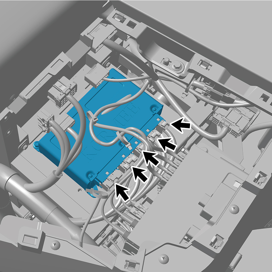
Disconnect 5 harness connectors of the EBS ECU
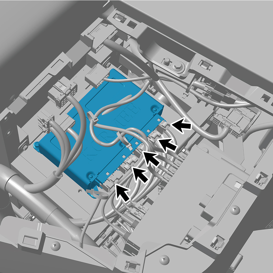
assembly.
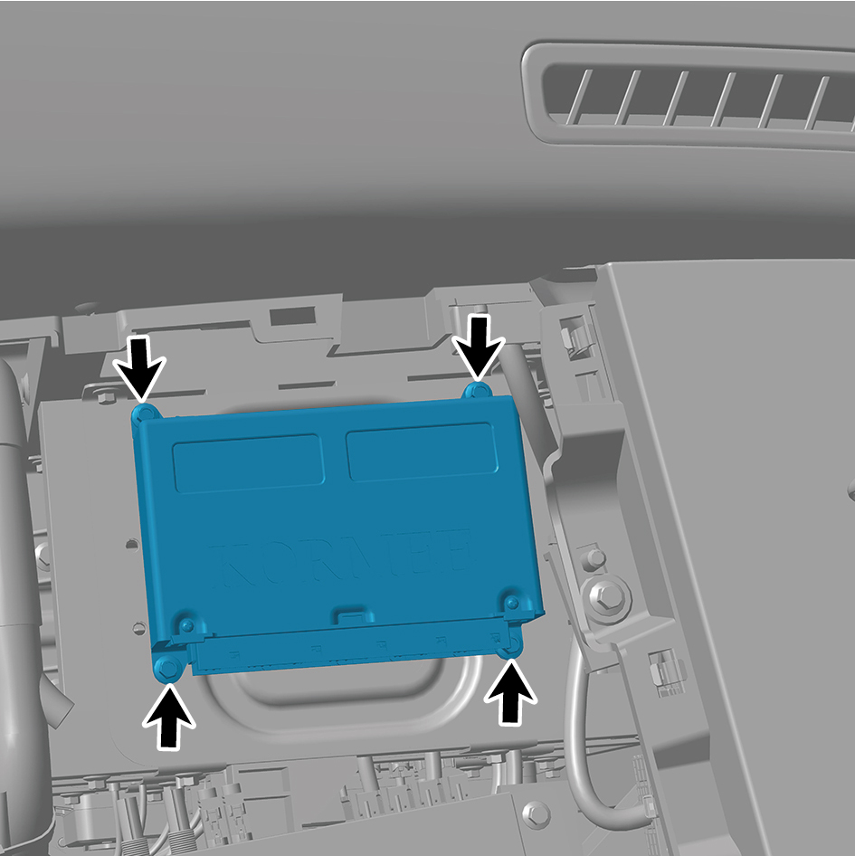
6
Remove 4 fixing bolts of the EBS ECU assembly.
7
Remove the EBS ECU assembly.
Installation Procedures
1
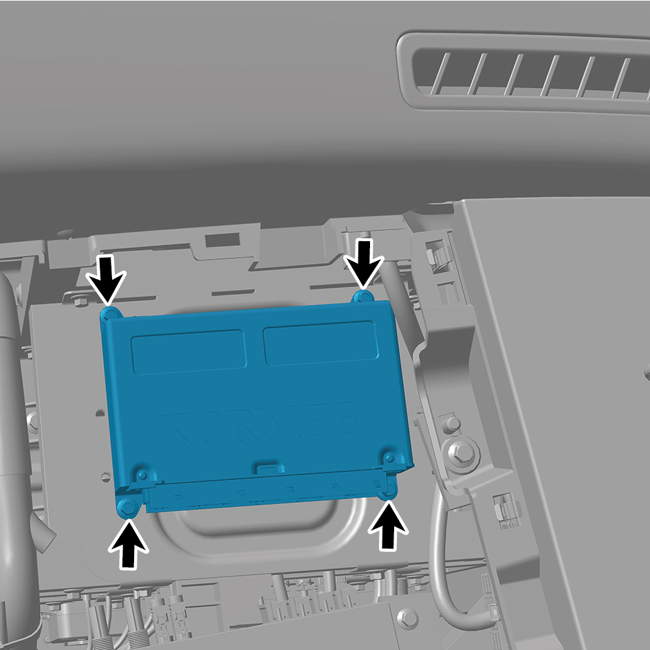
Move the EBS ECU assembly to the mounting position.
2
Install 4 fixing bolts of the EBS ECU assembly.
Torque: 8 +/- .75 (ft lbs)
3
Connect 5 harness connectors of the EBS ECU assembly.
caution
The harness is firmly connected following the
principal of "insert until a click is heard for
confirmation".
4
Install the IP left upper trim panel assembly.
5
Connect the battery negative cable.
6
Close the front flip cover plate.
7
Close the door.
caution
After replacing the EBS ECU assembly, it is
necessary to connect a scan tool for flashing and
recalibrate the zero position.
8.18.5.2 Replacement of Steering Angle Sensor Assembly
Sensor Assembly
Removal Procedures
1
Open the door.
2
Open the front flip cover plate.
3
Disconnect the battery negative cable.
caution
power down the high-voltage system before
disconnecting the negative pole of the storage
battery.
4
Remove the combination switch upper shield assembly.
5
Remove the combination switch lower shield.
6
Remove the driver horn cover assembly.
7
Remove the steering wheel assembly.
8
Remove the clock spring.
9
Remove the combination switch.
10
Remove the combination switch fixing bracket.
11
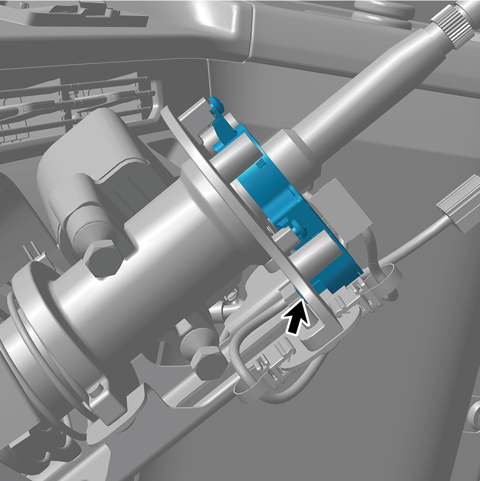
Disconnect 1 harness connector of the steering angle
sensor assembly.
12
Remove 3 fixing screws of the steering angle sensor
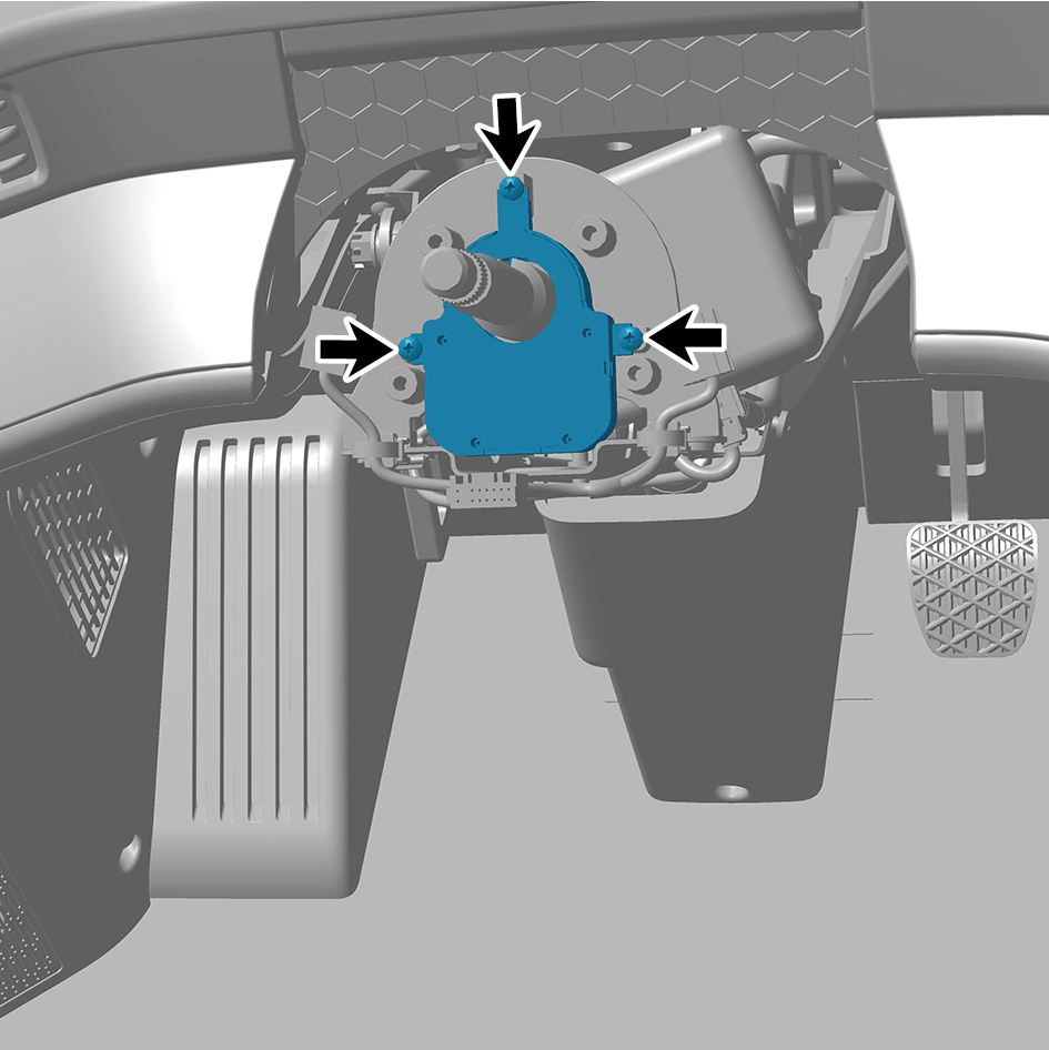
assembly.
13
Remove the steering angle sensor assembly.
Installation Procedures
1
Move the steering angle sensor assembly to the mounting
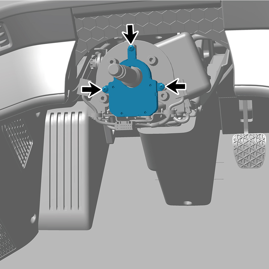
position.
2
Install 3 fixing screws of the steering angle sensor
assembly.
3
Connect 1 harness connector of the steering angle sensor
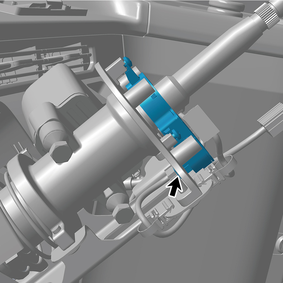
assembly.
caution
The harness is firmly connected following the
principal of "insert until a click is heard for
confirmation".
4
Install the combination switch fixing bracket.
5
Install the combination switch.
6
Install the clock spring.
7
Install the steering wheel assembly.
8
Install the driver horn cover assembly.
9
Install the combination switch lower shield.
10
Install the combination switch upper shield assembly.
11
Connect the battery negative cable.
12
Close the front flip cover plate.
13
Close the door.
caution
After part replacement, it is necessary to recalibrate
the zero position.
8.18.5.3 Replacement of Yaw Sensor Assembly
Assembly
Removal Procedures
1
Open the door.
2
Open the front flip cover plate.
3
Disconnect the battery negative cable.
caution
power down the high-voltage system before
disconnecting the negative pole of the storage
battery.
4
Disconnect 1 harness connector of the yaw sensor
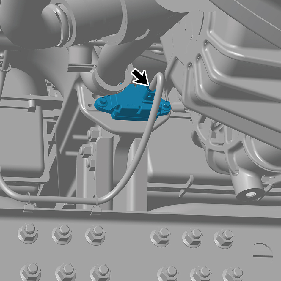
assembly.
5
Remove 2 fixing bolts of the yaw sensor assembly.
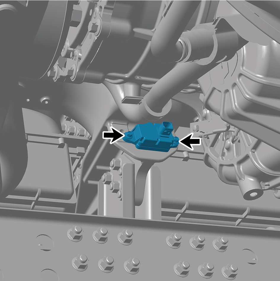
6
Remove the yaw sensor assembly.
Installation Procedures
1
Move the yaw sensor assembly to the mounting position.
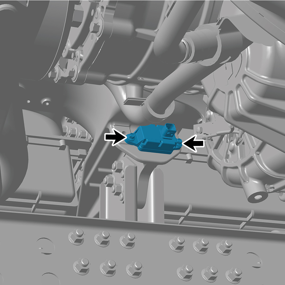
2
Install 2 fixing bolts of the yaw sensor assembly.
Torque:18.5 +/- 2 (ft lbs)
3
Connect 1 harness connector of the yaw sensor
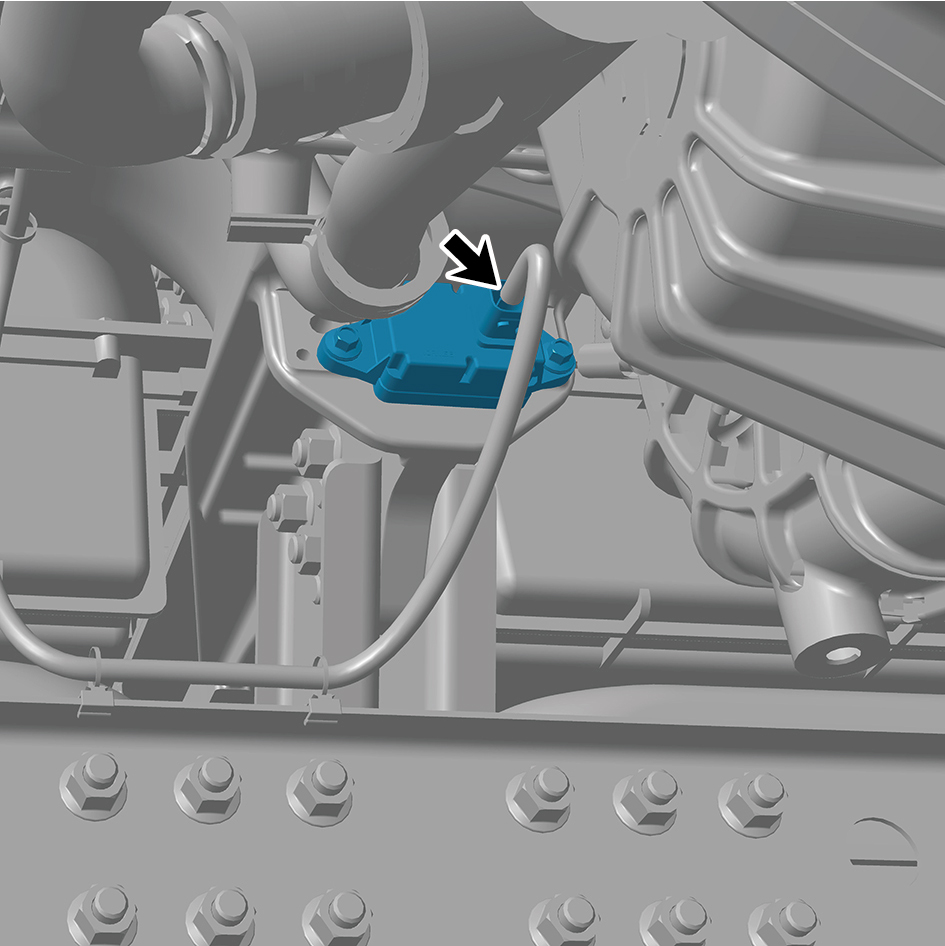
assembly.
caution
The harness is firmly connected following the
principal of "insert until a click is heard for
confirmation".
4
Connect the battery negative cable.
5
Close the front flip cover plate.
6
Close the door.
caution
After part replacement, it is necessary to recalibrate
the zero position.