← Back to Contents
8 Chassis / 8.17 Air Reservoir Device | PDF pages 2165-2192
8.17 Air Reservoir Device
8.17 Air Reservoir Device
8.17.1 Dismantling and Installation
8.17.1.1 Replacement of Air Compressor Assembly
Assembly
Removal Procedures
1
Release air pressure from the brake system.
2
Open the door.
3
Open the front flip cover plate.
4
Disconnect the battery negative cable.
5
Perform power-off of high voltage system.
6
Jack the front end of the vehicle.
7
Drain coolant from the power system.
8
Remove the back integrated bracket side cover plate
assembly (left).
9
Remove the back integrated bracket side cover plate
assembly (right).
10
Remove the back integrated bracket middle cover plate
assembly.
11
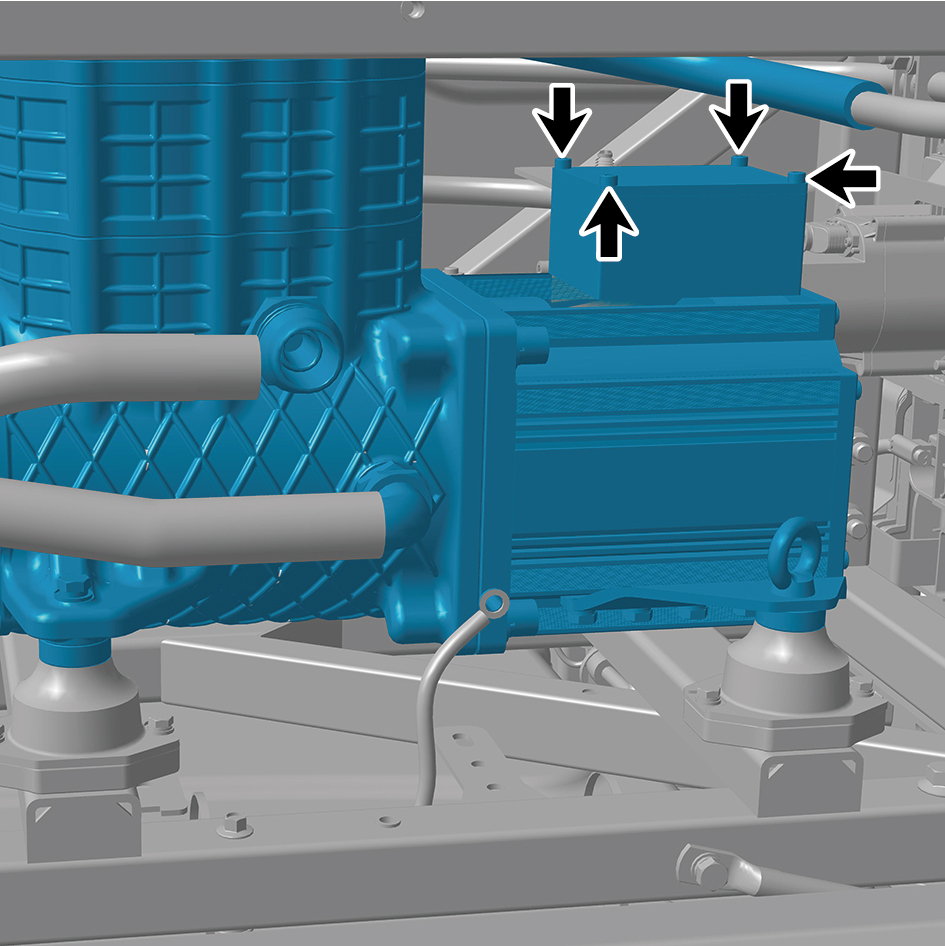
Remove the 4 fixing screws of the cover plate and detach
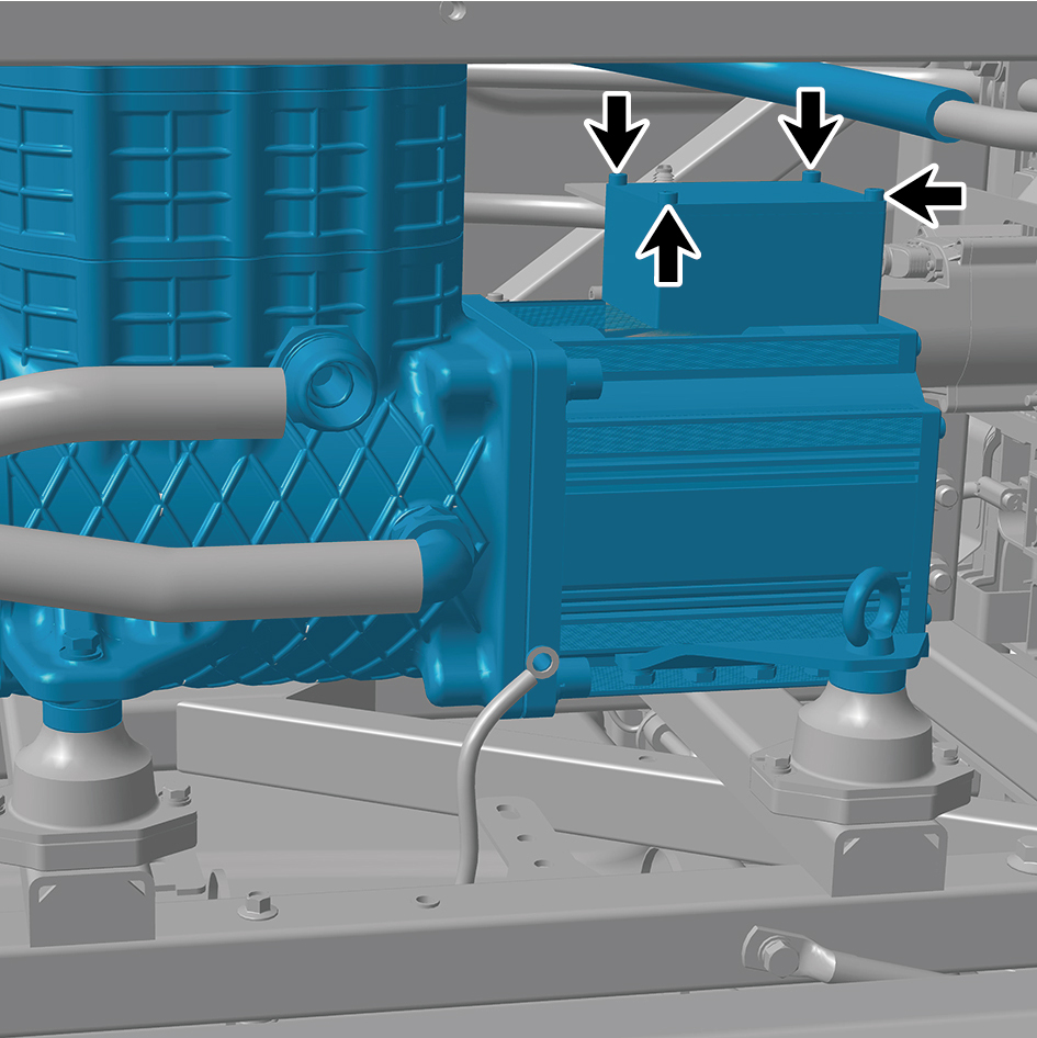
the cover plate.
12
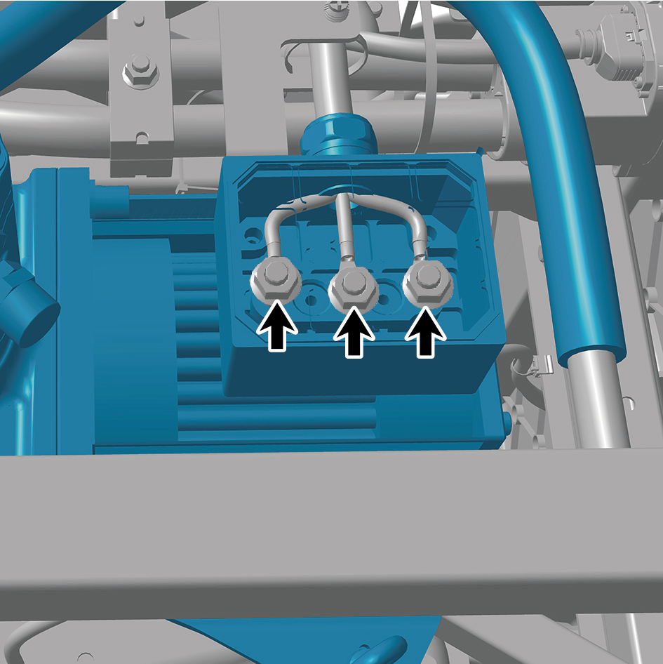
Remove the 3 fixing bolts of the harness.
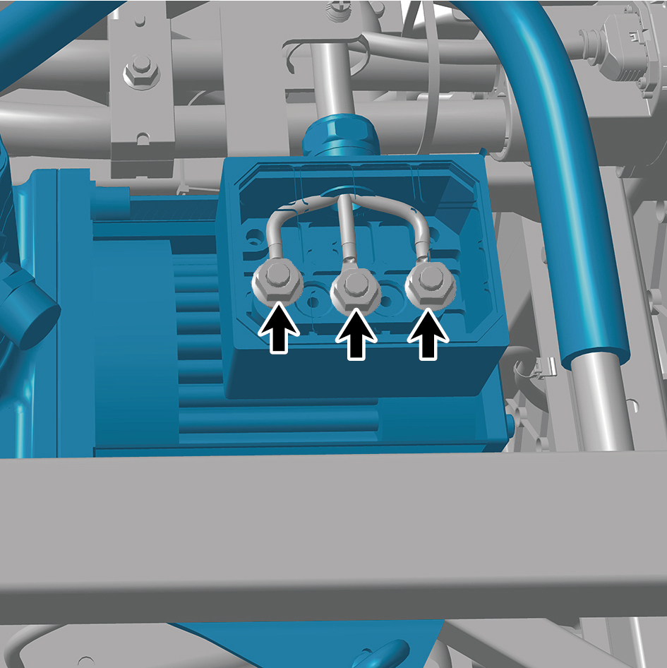
13
Disconnect 4 pipelines of the air compressor assembly.
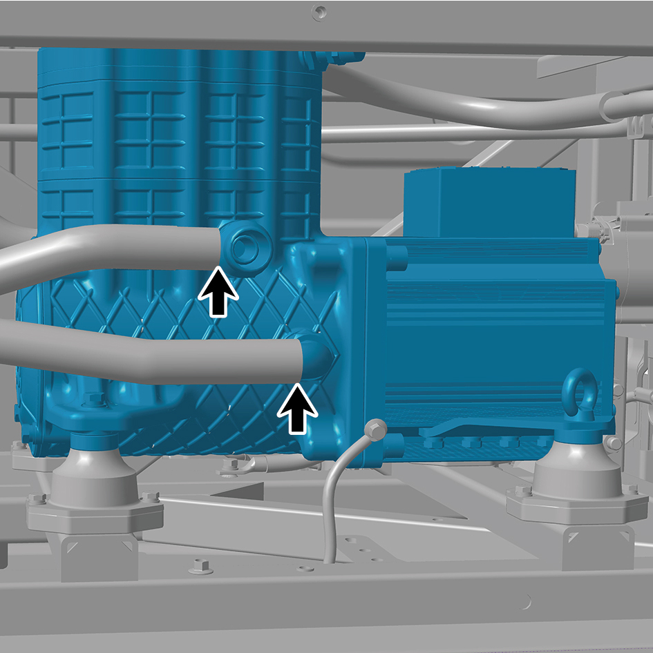
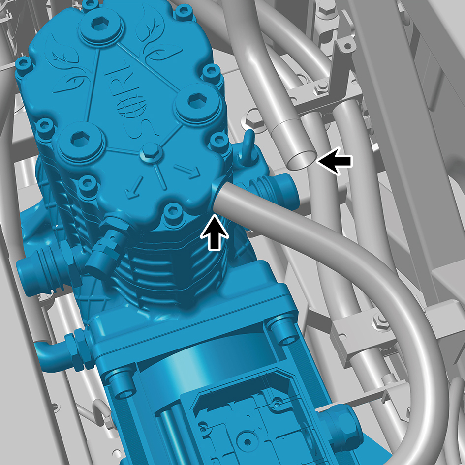
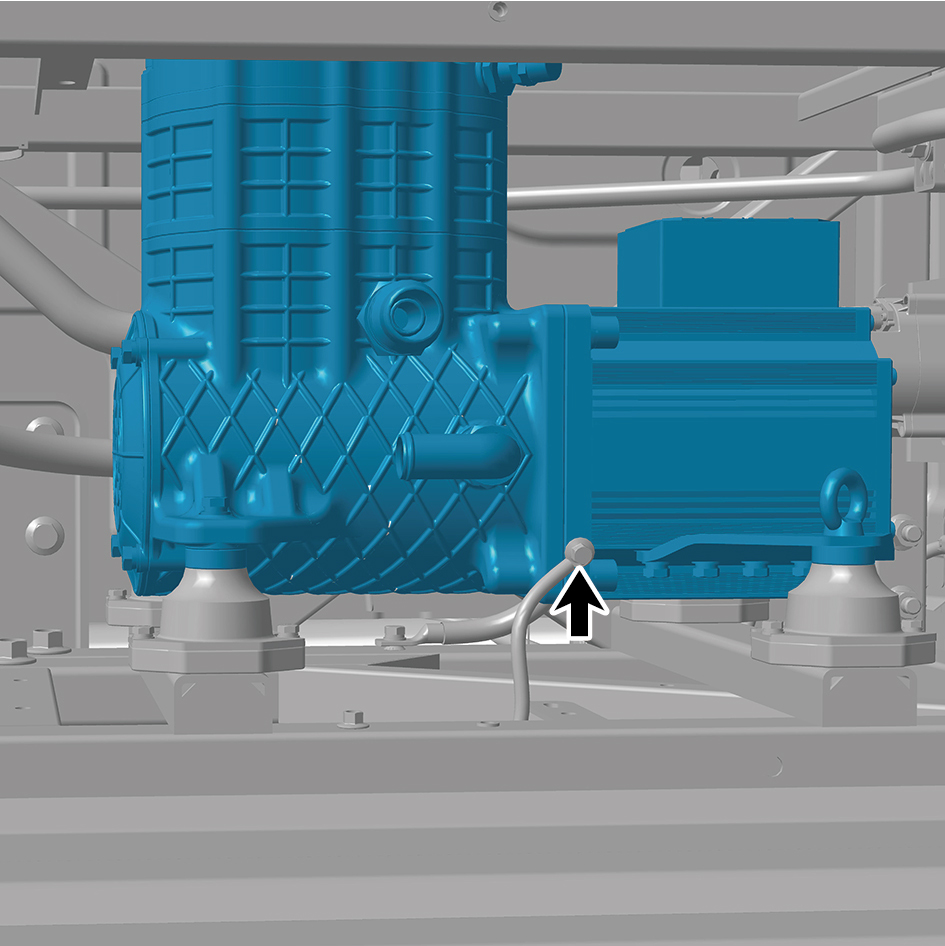
14
Remove 1 fixing bolt of the ground harness.
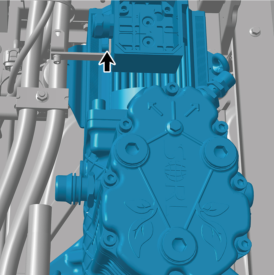
15
Remove 1 fixing bolt of the harness bracket.
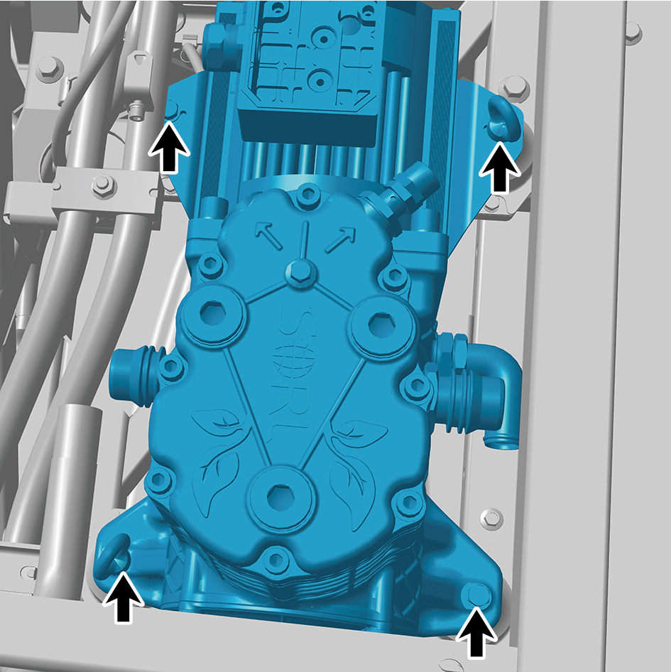
16
Remove 4 fixing bolts of the air compressor assembly.
17
Remove the air compressor assembly.
Installation Procedures
1
Move the air compressor assembly to the mounting
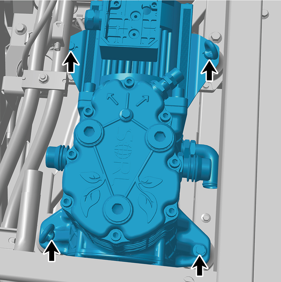
position.
2
Install 4 fixing bolts of the air compressor assembly.
Torque: 70 +/- 3.5 (ft lbs)
3
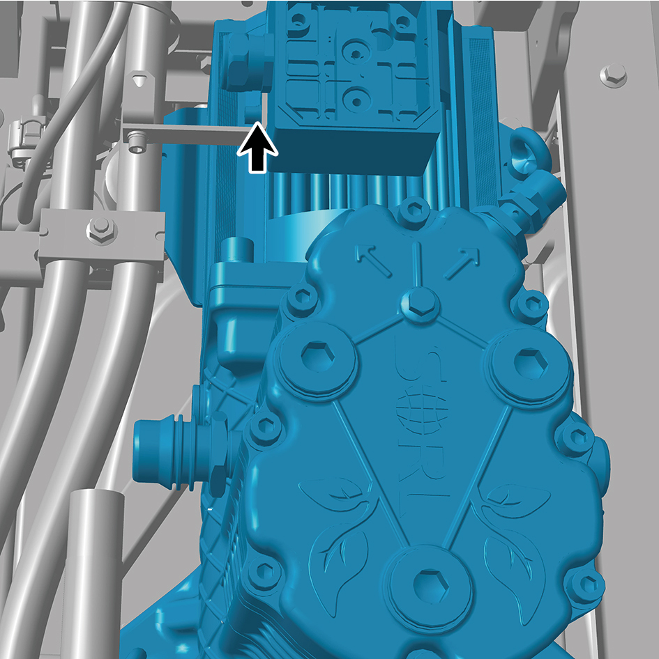
Install 1 fixing bolt of the harness bracket.
4
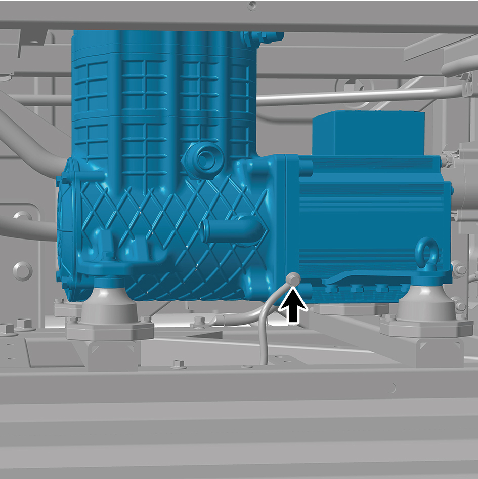
Install 1 fixing bolt of the ground wire.
5
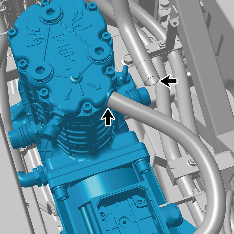
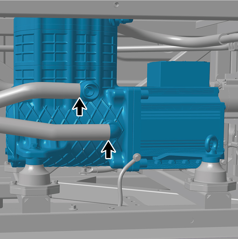
Connect 4 pipelines of the air compressor assembly.
6
Install the 3 fixing bolts of the harness.
7
Install the 4 fixing screws of the cover plate.
8
Install the back integrated bracket middle cover plate
assembly.
9
Install the back integrated bracket side cover plate
assembly (right).
10
Install the back integrated bracket side cover plate
assembly (left).
11
Fill coolant in the power system.
12
Lower the front end of the vehicle.
13
Perform power-on of the high voltage system.
14
Connect the battery negative cable.
15
Close the front flip cover plate.
16
Close the door.
8.17.1.2 Replacement of Air Filter Assembly
Removal Procedures
1
Release air pressure from the brake system.
2
Open the door.
3
Open the front flip cover plate.
4
Disconnect the battery negative cable.
5
Perform power-off of high voltage system.
6
Remove the back integrated bracket side cover plate
assembly (left).
7
Remove the back integrated bracket side cover plate
assembly (right).
8
Remove the back integrated bracket middle cover plate
assembly.
9
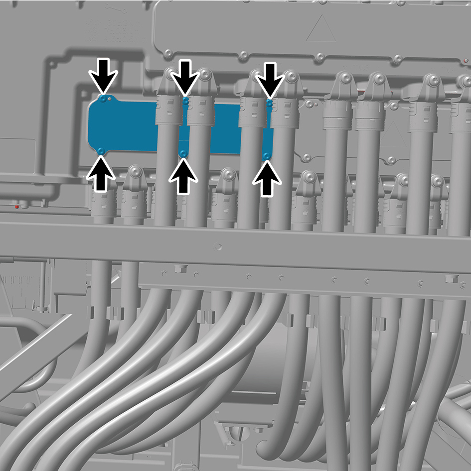
Remove 6 fixing screws of the cover plate.
10
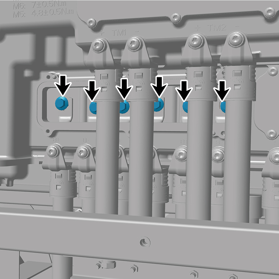
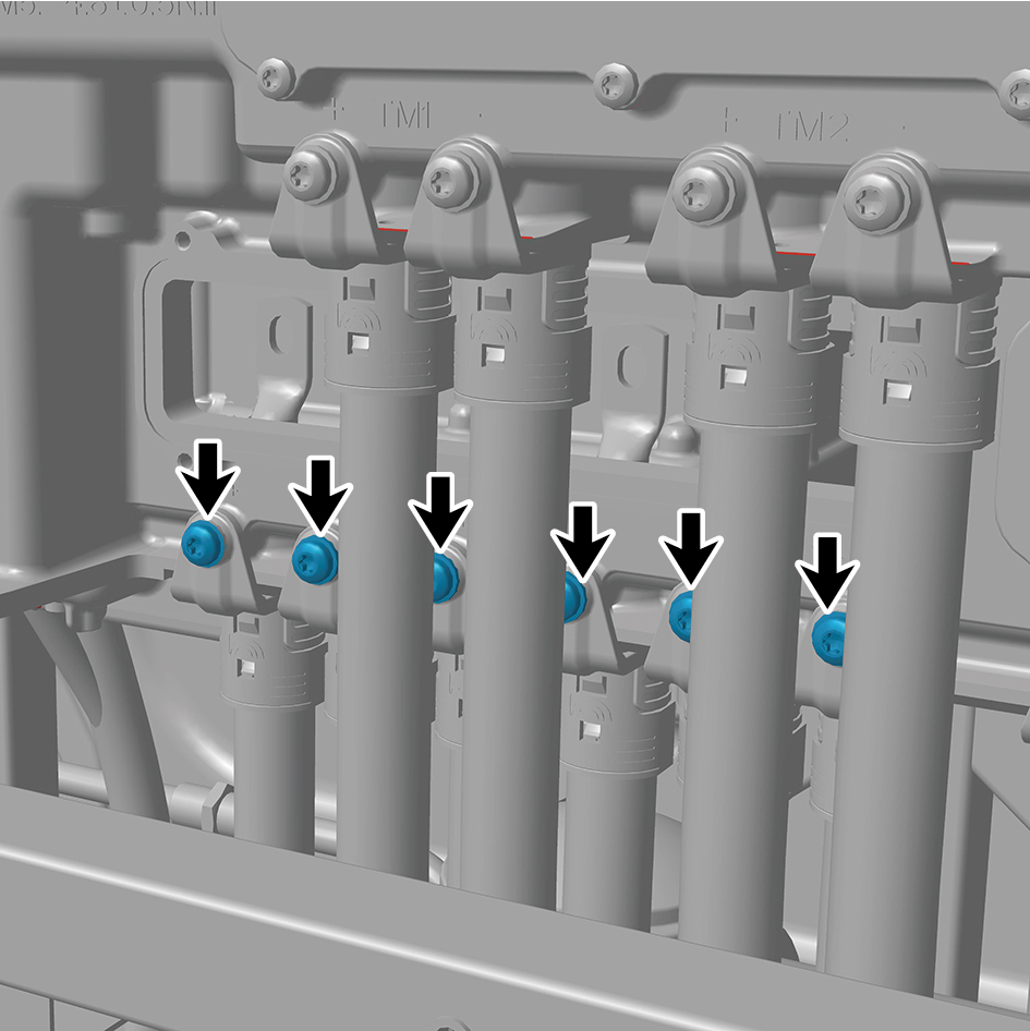
Remove 6 fixing bolts of the high voltage harness.
11
Remove 6 fixing bolts of the high voltage harness.
12
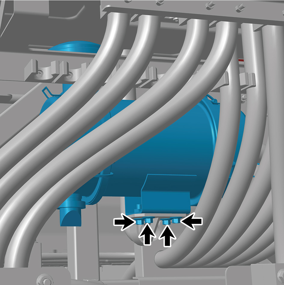
Remove 4 fixing bolts of the air filter assembly.
13
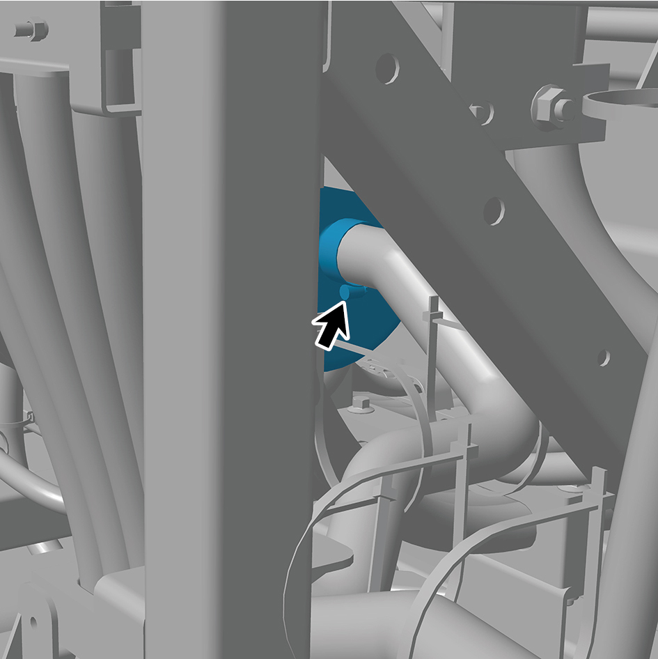
Disengage 1 clamp of the air filter assembly.
14
Remove the air filter assembly.
Installation Procedures
1
Move the air filter assembly to the mounting position.
2
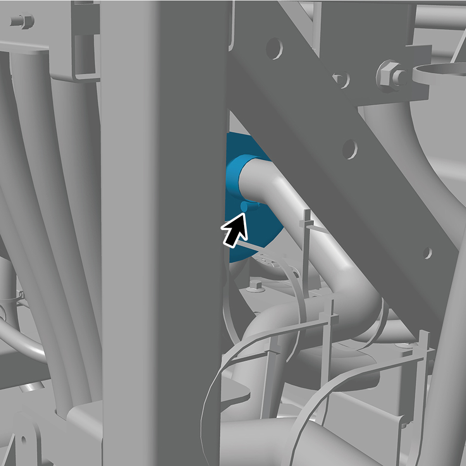
Connect 1 clamp of the air filter assembly.
3
Install 4 fixing bolts of the air filter assembly.
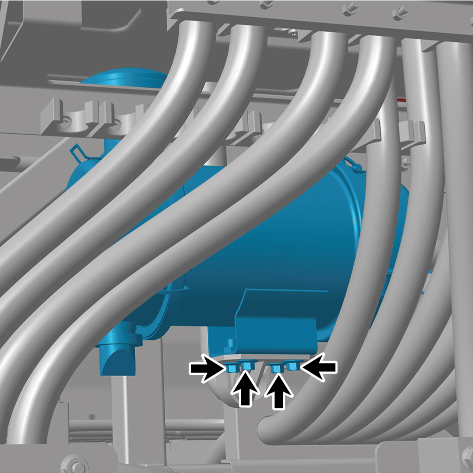
Torque: 18.5 +/- 2 (ft lbs)
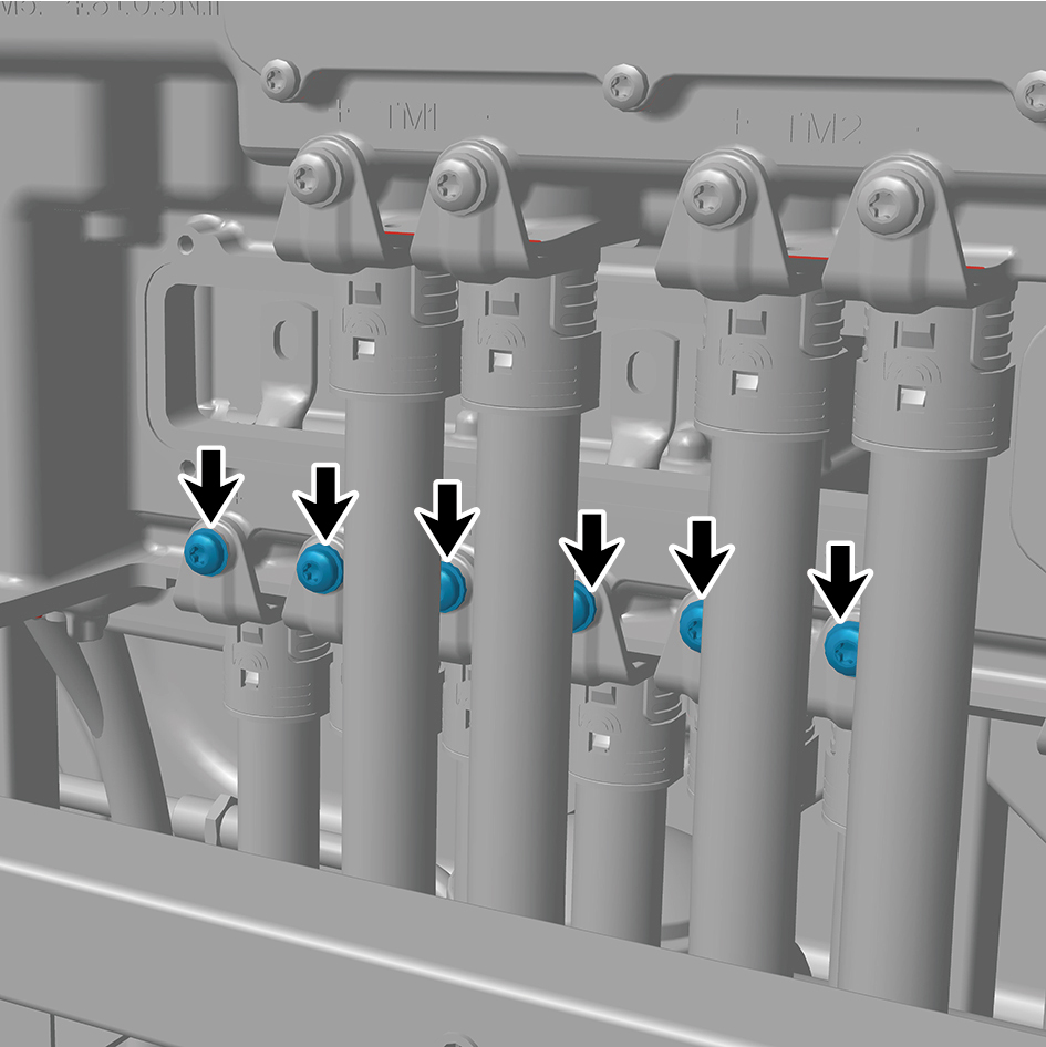
4
Install 6 fixing screws of the high voltage harness.
5
Install 6 fixing bolts of the high voltage harness.
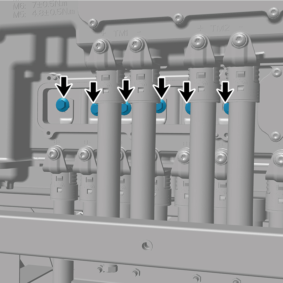
Torque:22 +/- 2 (ft lbs)
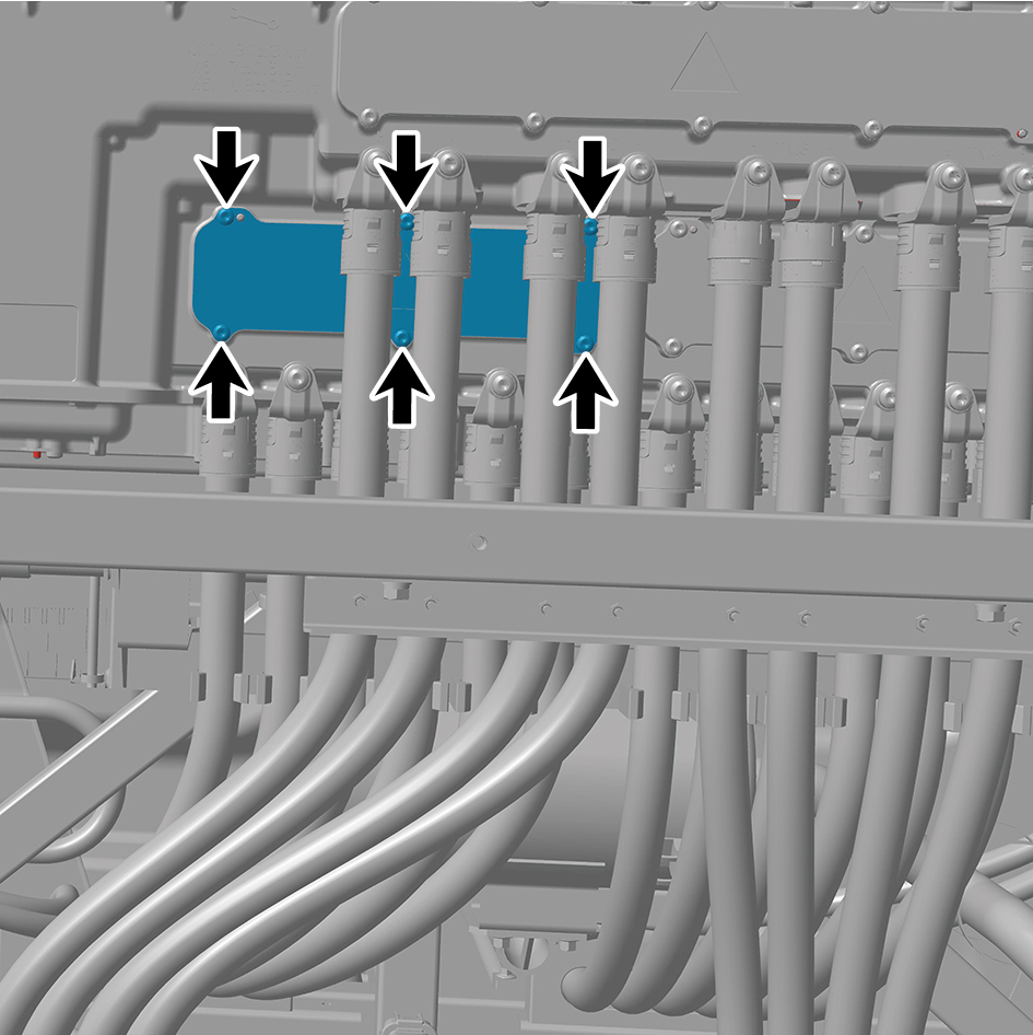
6
Install the 6 fixing screws of the cover plate.
7
Install the back integrated bracket middle cover plate
assembly.
8
Install the back integrated bracket side cover plate
assembly (right).
9
Install the back integrated bracket side cover plate
assembly (left).
10
Perform power-on of the high voltage system.
11
Connect the battery negative cable.
12
Close the front flip cover plate.
13
Close the door.
8.17.1.3 Replacement of Air Inlet Hose
Removal Procedures
1
Release air pressure from the brake system.
2
Remove the back integrated bracket side cover plate
assembly (left).
3
Remove the back integrated bracket side cover plate
assembly (right).
4
Remove the back integrated bracket middle cover plate
assembly.
5
Detach the air inlet hose.
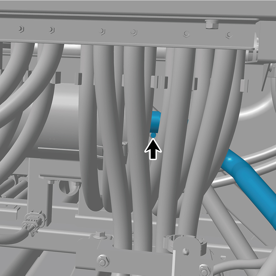
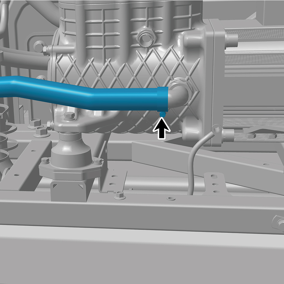
Installation Procedures
1
Install the air inlet hose.
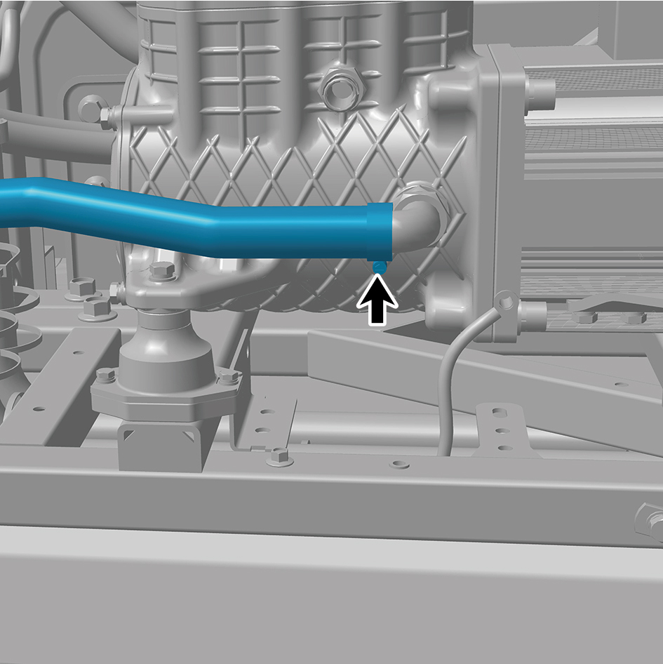
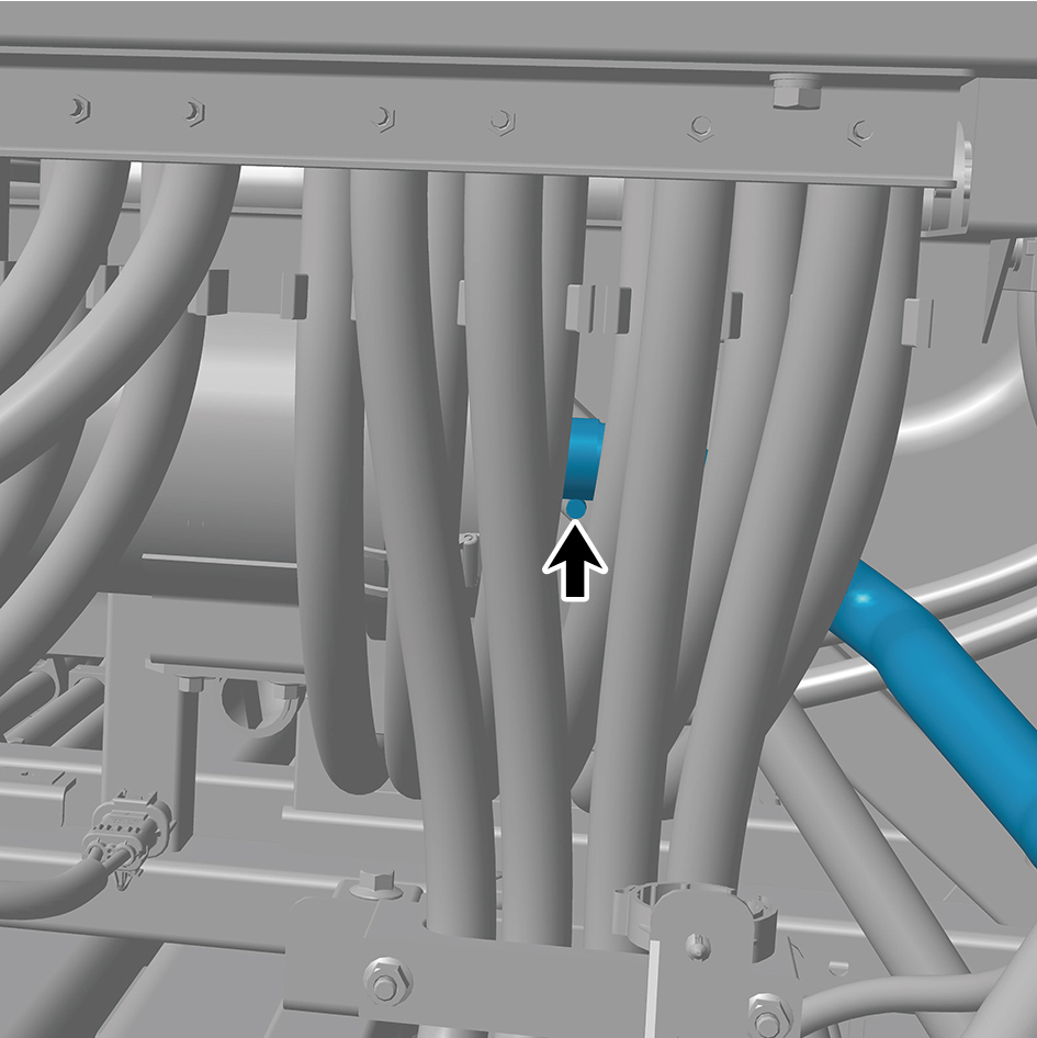
2
Install the back integrated bracket middle cover plate
assembly.
3
Install the back integrated bracket side cover plate
assembly (right).
4
Install the back integrated bracket side cover plate
assembly (left).
8.17.1.4 Replacement of Air Handling Unit Assembly
Assembly
Removal Procedures
1
Release air pressure from the brake system.
2
Open the door.
3
Open the front flip cover plate.
4
Disconnect the battery negative cable.
caution
power down the high-voltage system before
disconnecting the negative pole of the storage
battery.
5
Remove the back integrated bracket side cover plate
assembly (left).
6
Remove the back integrated bracket side cover plate
assembly (right).
7
Remove the back integrated bracket middle cover plate
assembly.
8
Disconnect 2 harness connectors of the air handling unit
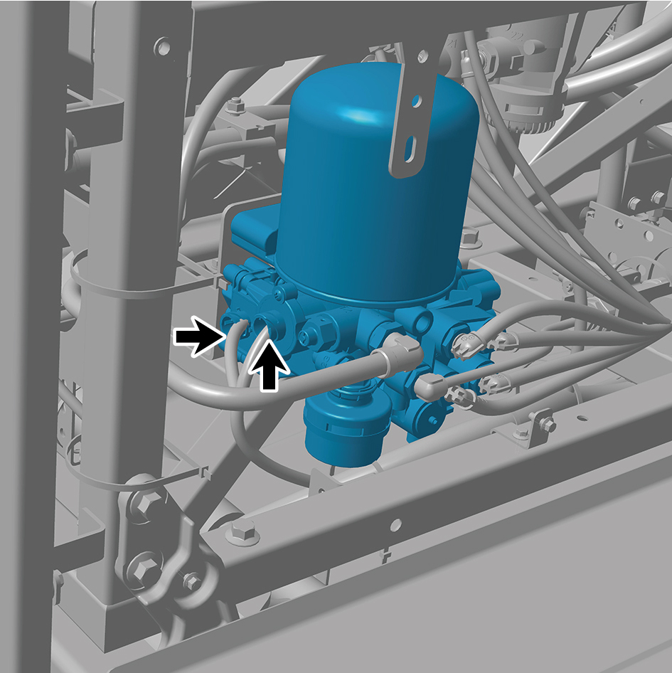
assembly.
9
Disconnect 6 air pipes of the air handling unit assembly.
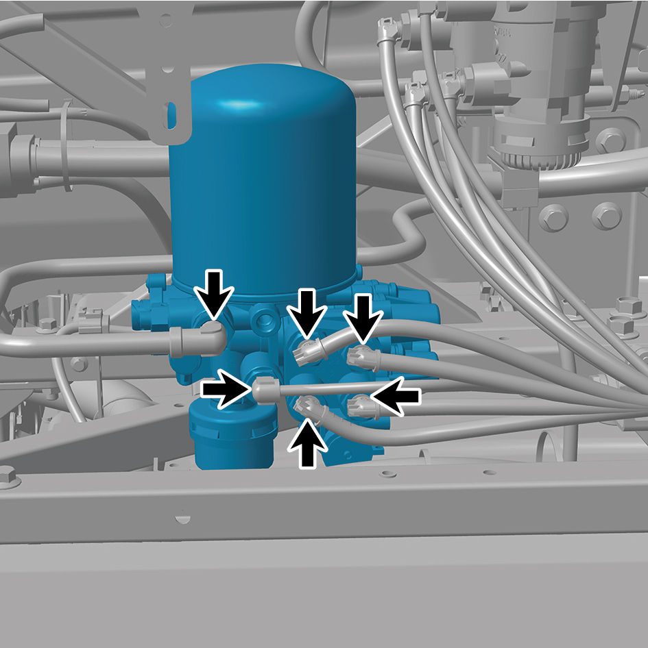
10
Remove 3 fixing bolts of the air handling unit assembly.
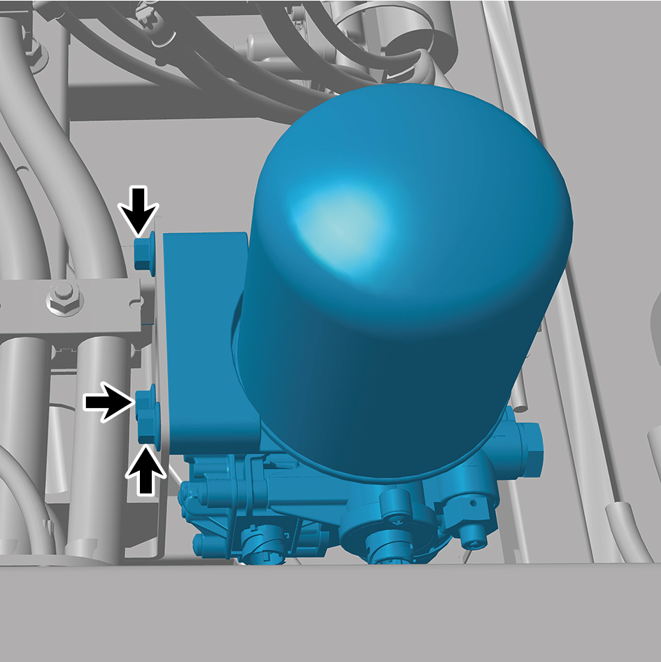
11
Remove the air handling unit assembly.
Installation Procedures
1
Move the air handling unit assembly to the mounting
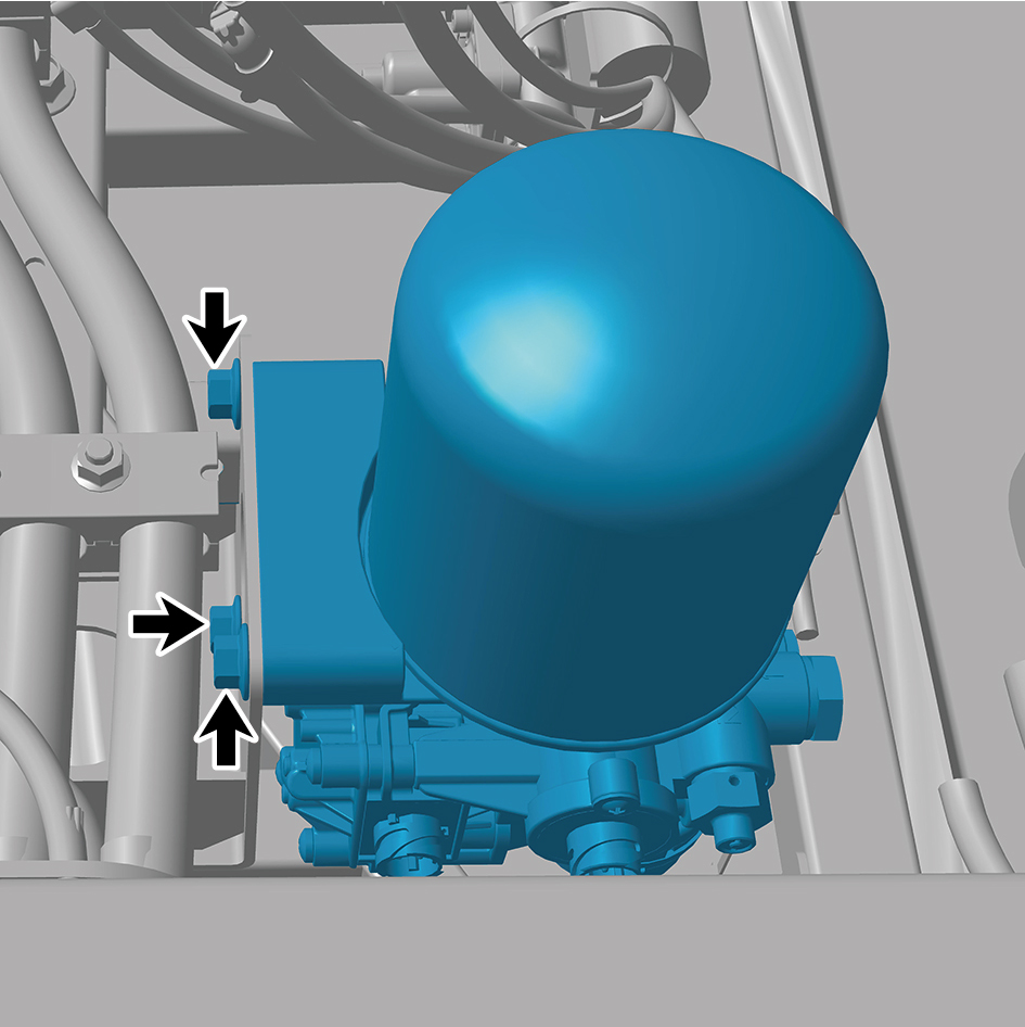
position.
2
Install 3 fixing bolts of the air handling unit assembly.
Torque:70 +/- 3.5 (ft lbs)
3
Connect 6 air pipes of the air handling unit assembly.
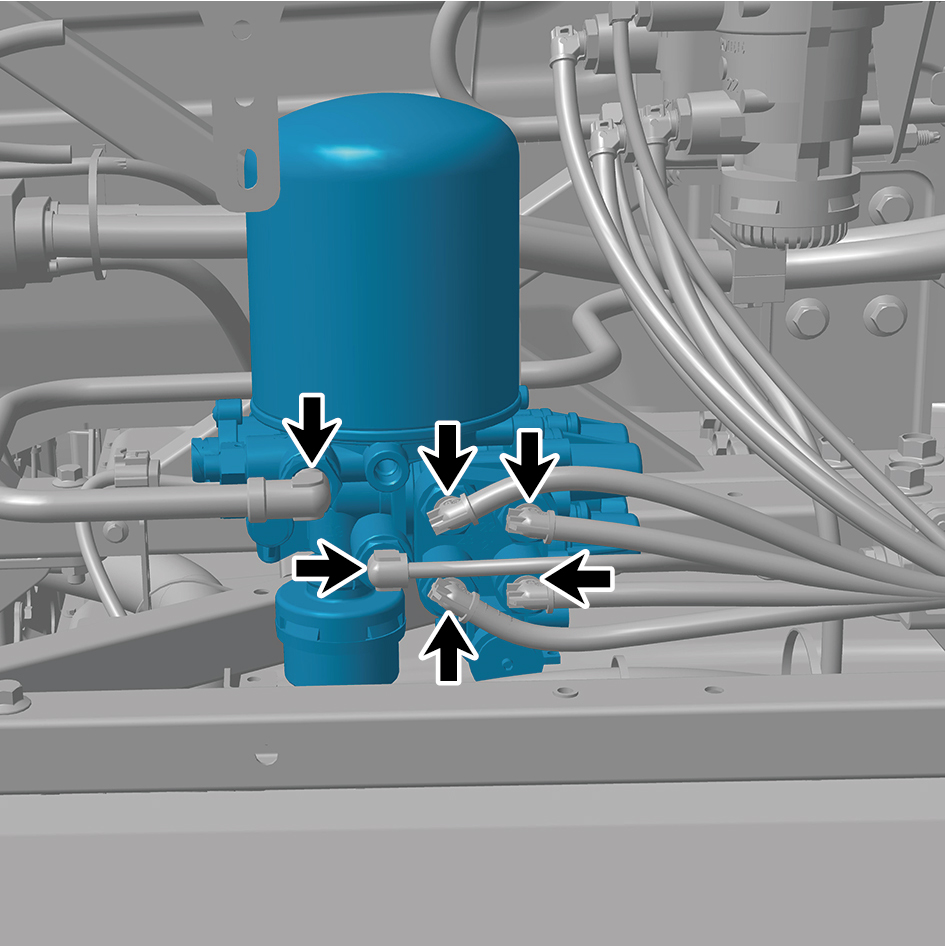
4
Connect 2 harness connectors of the air handling unit
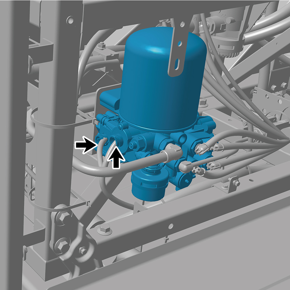
assembly.
caution
The harness is firmly connected following the
principal of "insert until a click is heard for
confirmation".
5
Install the back integrated bracket middle cover plate
assembly.
6
Install the back integrated bracket side cover plate
assembly (right).
7
Install the back integrated bracket side cover plate
assembly (left).
8
Connect the battery negative cable.
9
Close the front flip cover plate.
10
Close the door.
8.17.1.5 Replacement of Drain Valve (front)
Removal Procedures
1
Release air pressure from the brake system.
2
Remove the back integrated bracket side cover plate
assembly (left).
3
Remove the back integrated bracket side cover plate
assembly (right).
4
Remove the back integrated bracket middle cover plate
assembly.
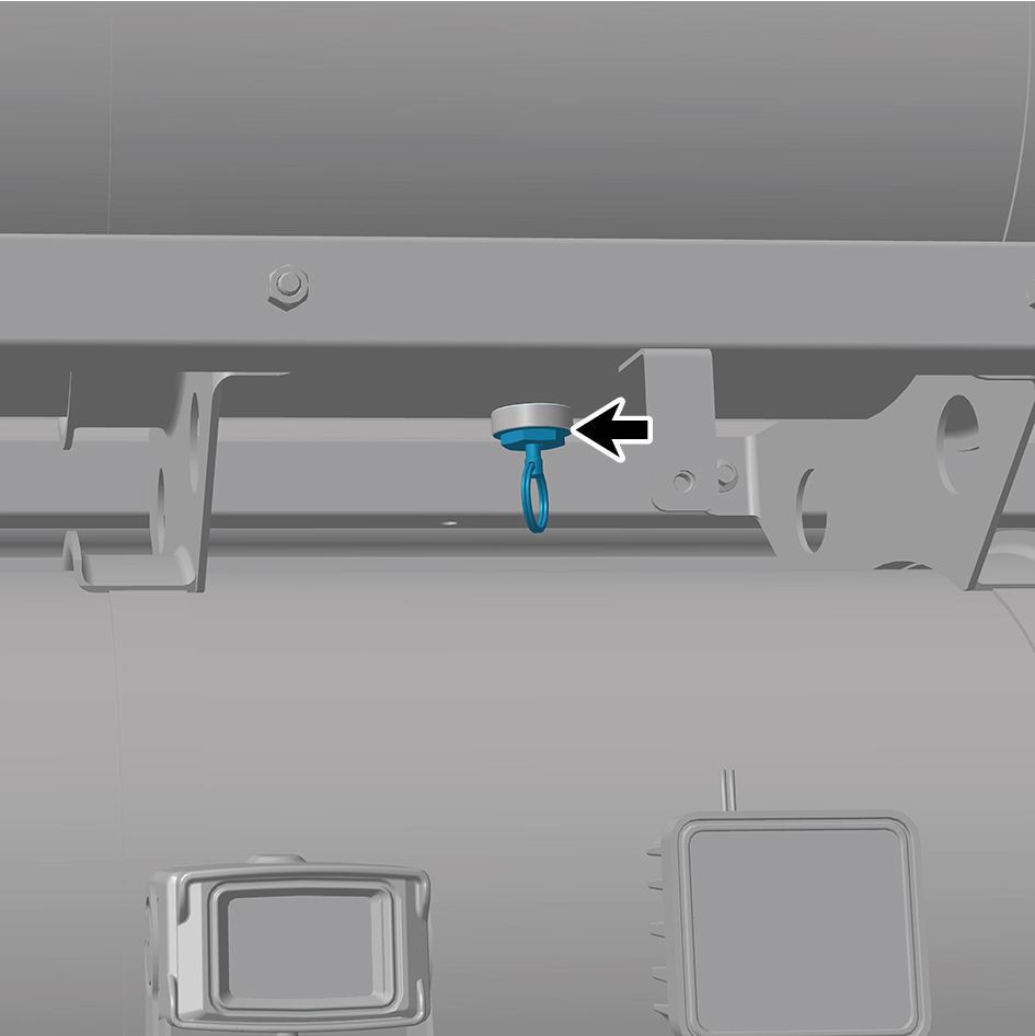
5
Remove the drain valve (front).
Installation Procedures
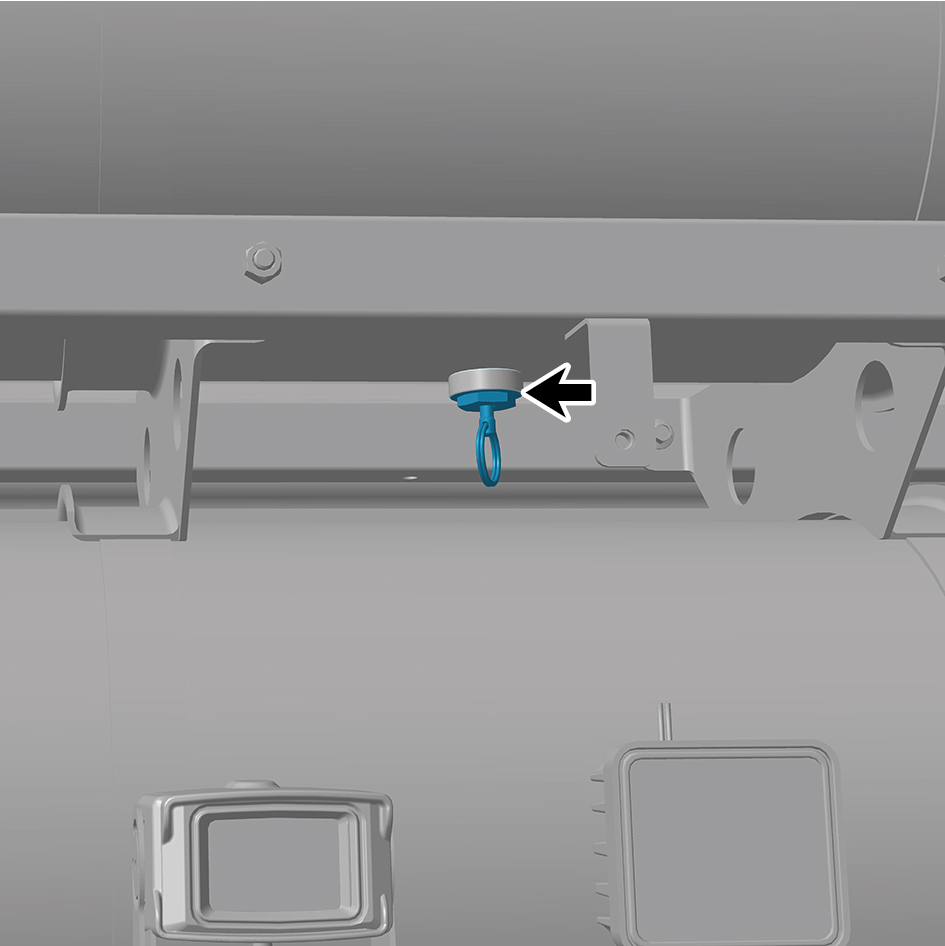
1
Move the drain valve (front) to the mounting position.
2
Install the back integrated bracket middle cover plate
assembly.
3
Install the back integrated bracket side cover plate
assembly (right).
4
Install the back integrated bracket side cover plate
assembly (left).
8.17.1.6 Replacement of Drain Valve (rear)
Removal Procedures
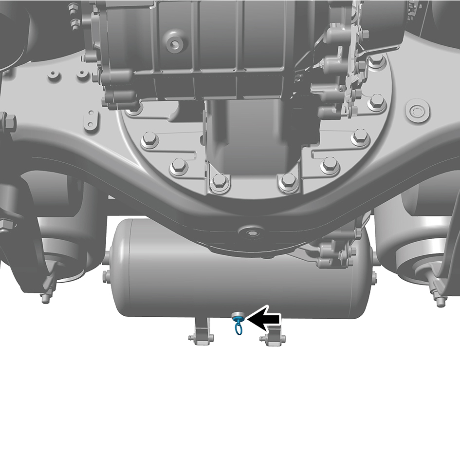
1
Release air pressure from the brake system.
2
Remove the drain valve (rear).
Installation Procedures
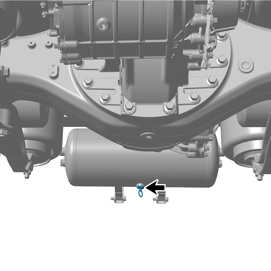
1
Move the drain valve (rear) to the mounting position.
8.17.1.7 Replacement of Air Reservoir Assembly
Assembly
Removal Procedures
1
Release air pressure from the brake system.
2
Disconnect 3 air pipes of the air reservoir assembly.
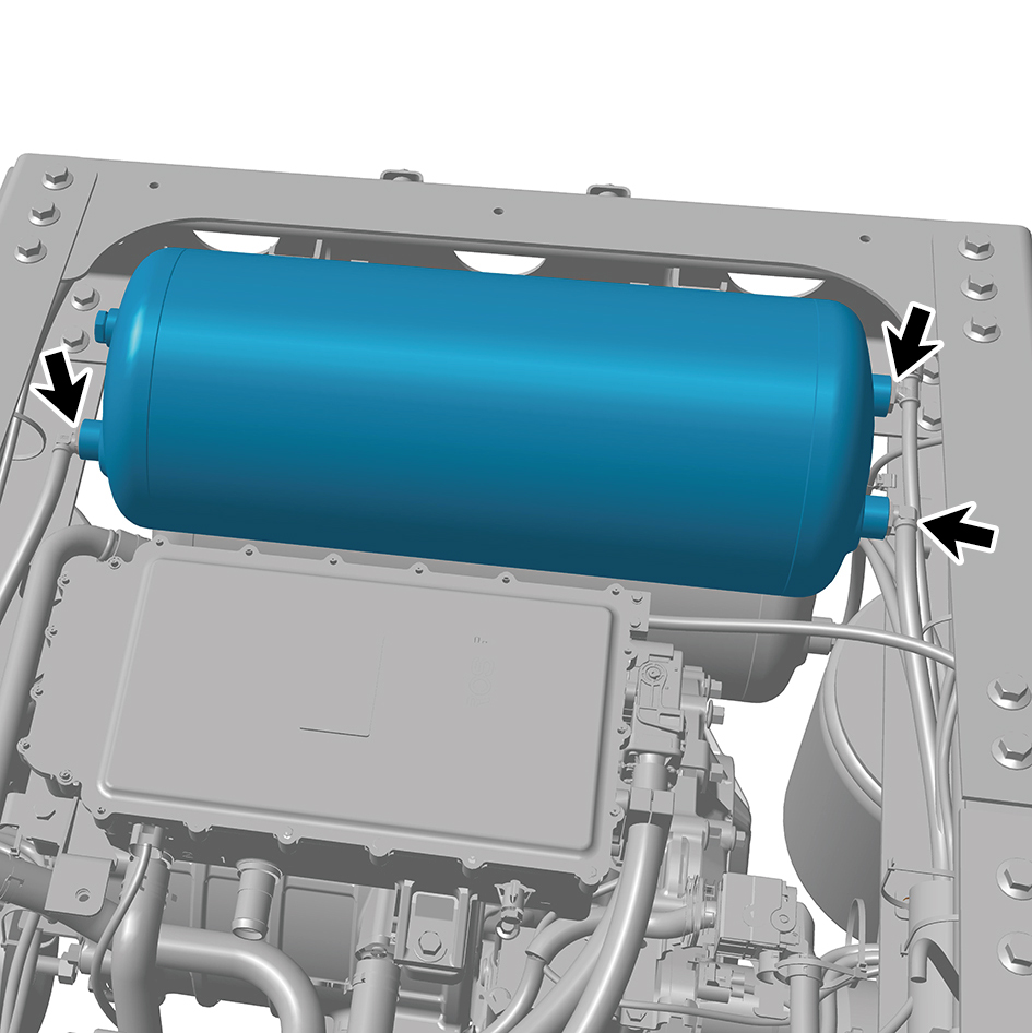
3
Remove the air reservoir assembly.
Installation Procedures
1
Move the air reservoir assembly to the mounting position.
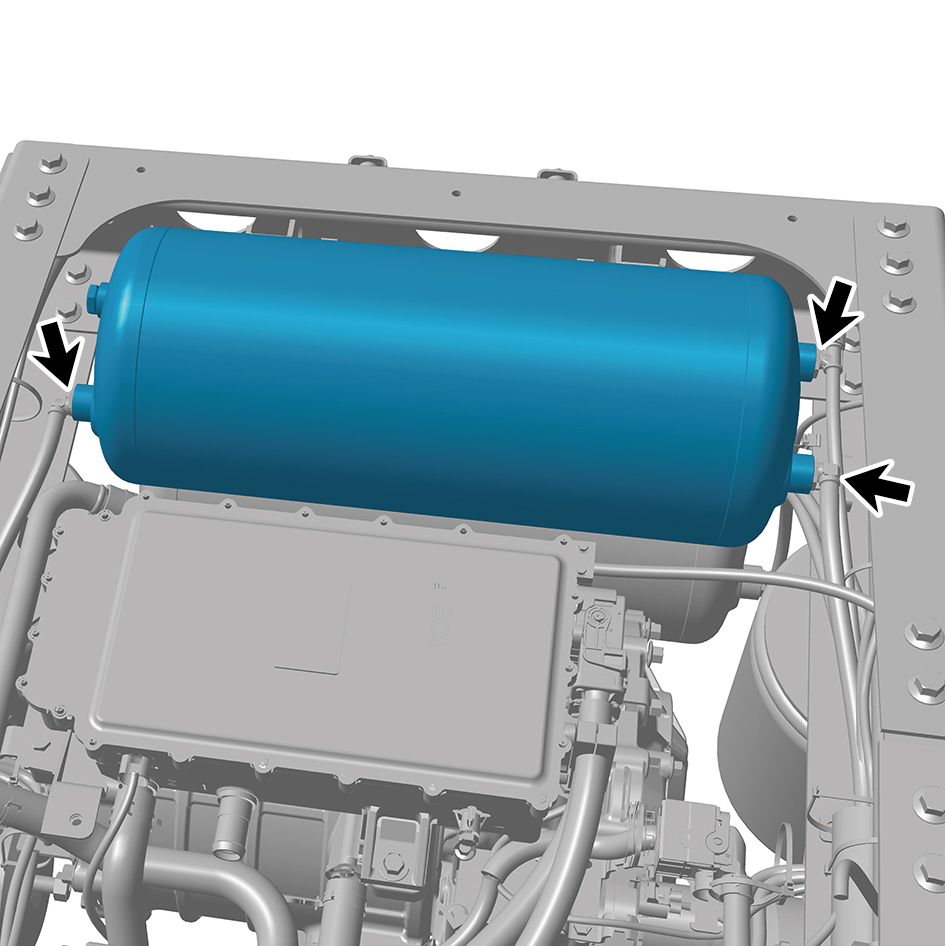
2
Connect 3 air pipes of the air reservoir assembly.
8.17.1.8 Replacement of Air Compressor Steel Pipe Assembly
Pipe Assembly
Removal Procedures
1
Release air pressure from the brake system.
2
Remove the back integrated bracket side cover plate
assembly (left).
3
Remove the back integrated bracket side cover plate
assembly (right).
4
Remove the back integrated bracket middle cover plate
assembly.
5
Remove the left deflector lower body.
6
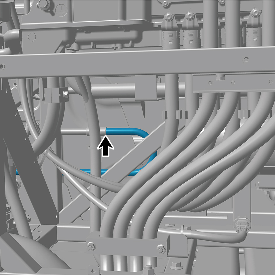
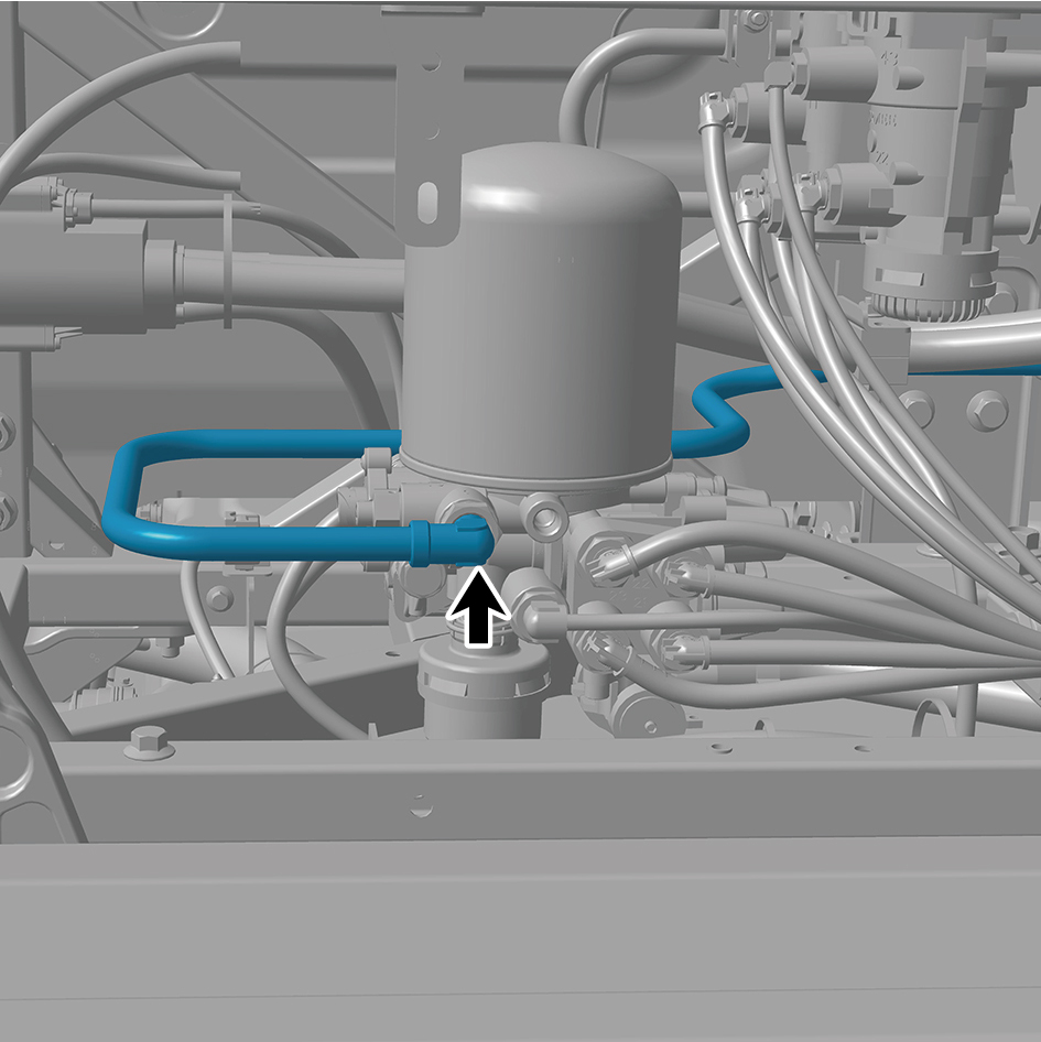
Remove the left charging cover plate assembly.
7
Disconnect 2 air pipes of the air compressor steel pipe
assembly.
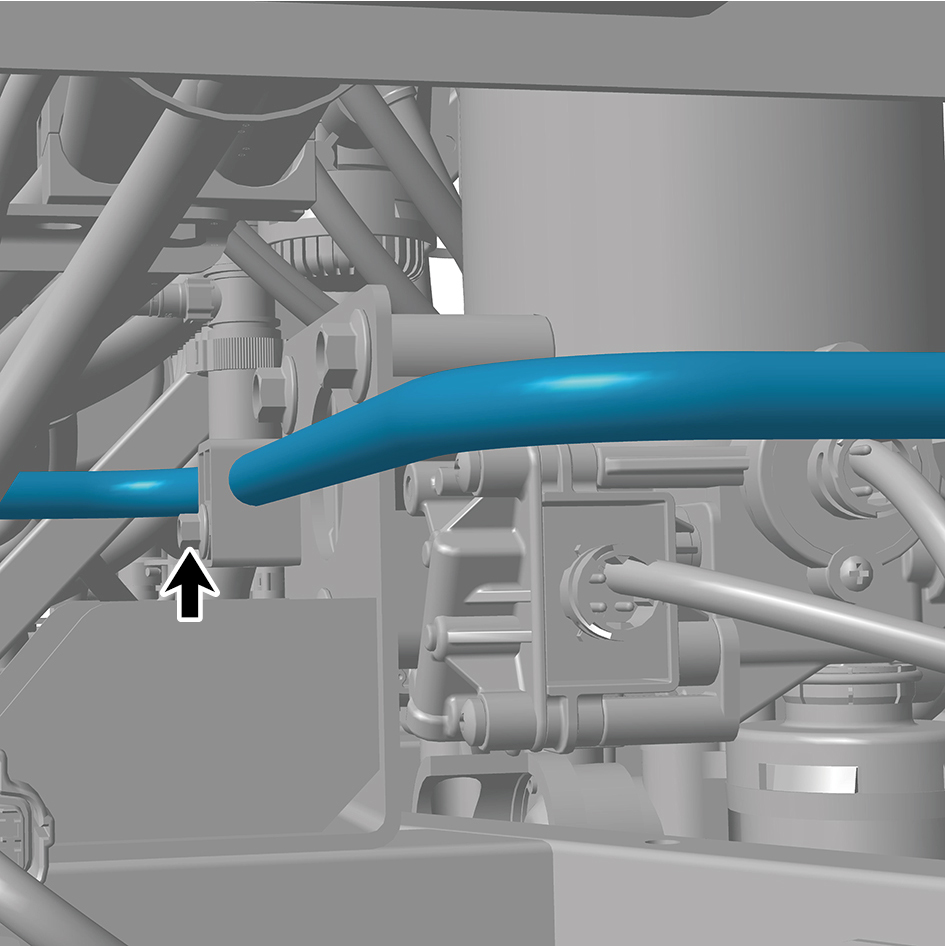
8
Remove 2 pipe clamps of the air compressor steel pipe
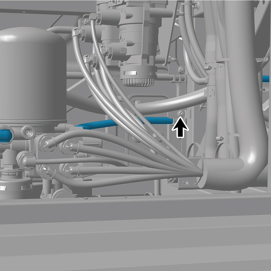
assembly, and remove the air compressor steel pipe
assembly.
Installation Procedures
1
Move the air compressor steel pipe assembly to the
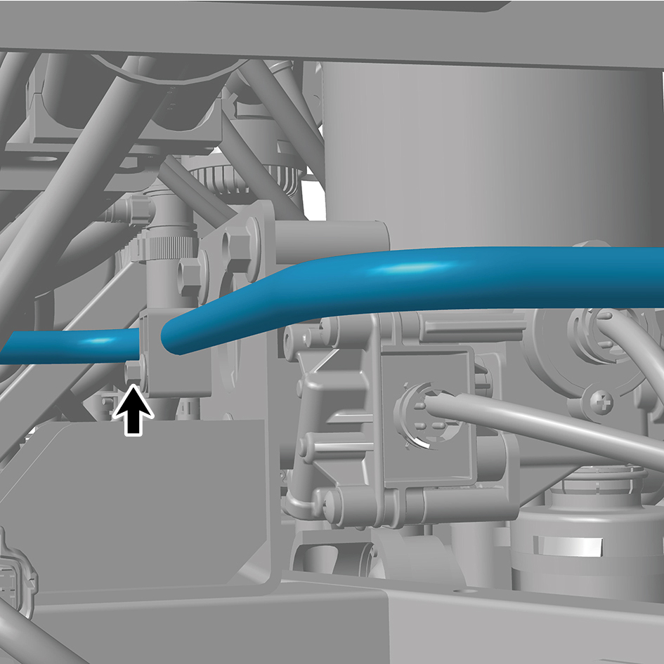
mounting position.
2
Install 2 pipe clamps of the air compressor steel pipe
assembly.
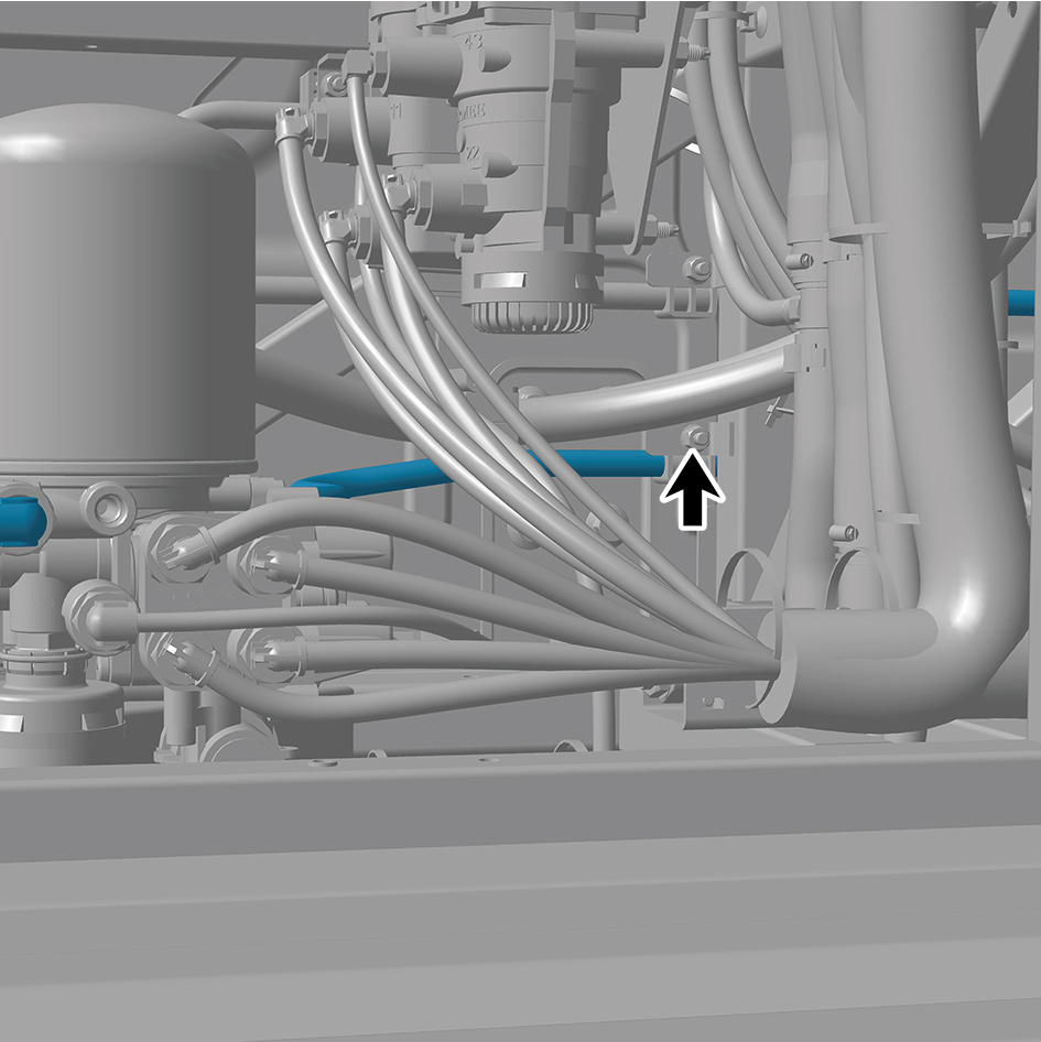
3
Connect 2 air pipes of the air compressor steel pipe
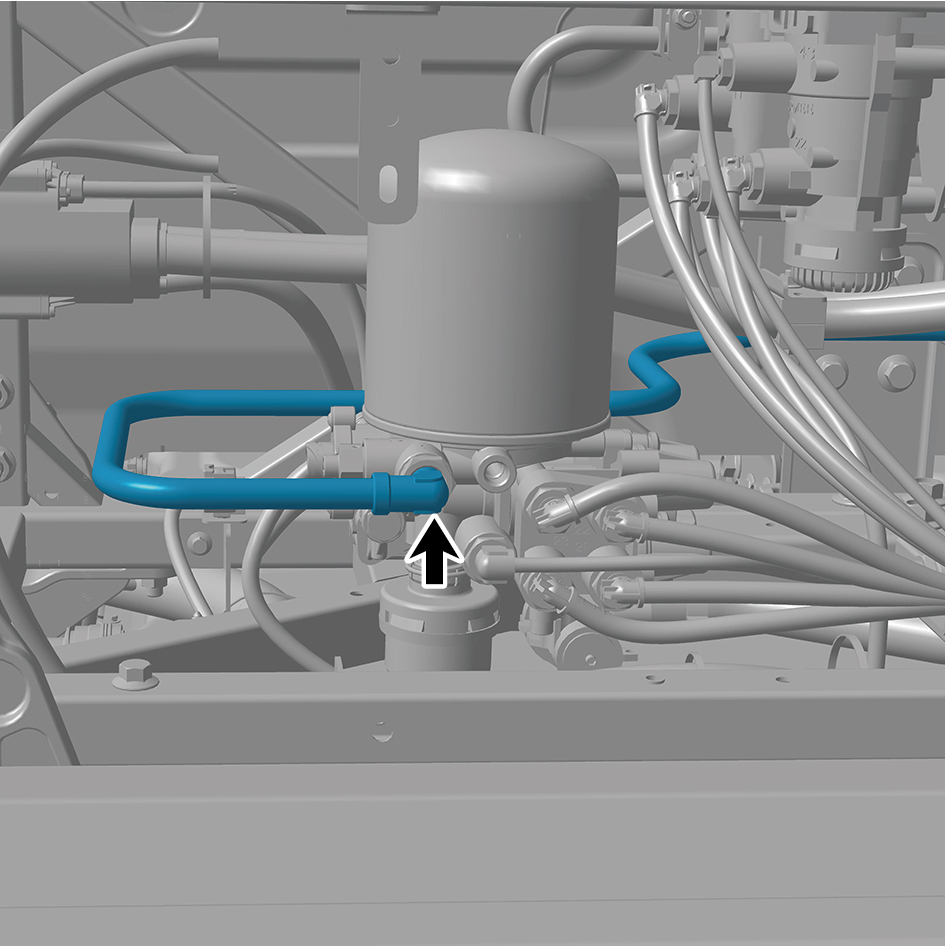
assembly.
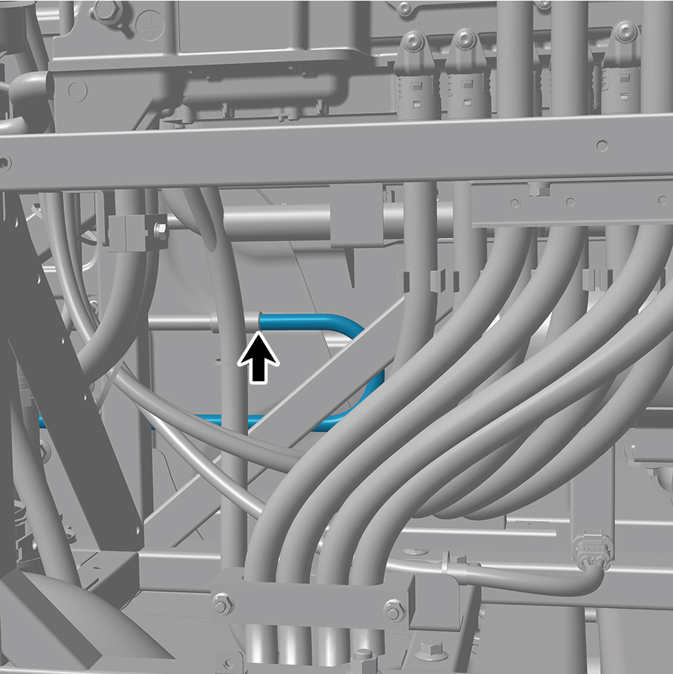
4
Install the left charging cover plate assembly.
5
Install the left deflector lower body.
6
Install the back integrated bracket middle cover plate
assembly.
7
Install the back integrated bracket side cover plate
assembly (right).
8
Install the back integrated bracket side cover plate
assembly (left).
8.17.1.9 Replacement of Air Compressor Steel Pipe Assembly (left)
Pipe Assembly (left)
Removal Procedures
1
Release air pressure from the brake system.
2
Remove the back integrated bracket side cover plate
assembly (left).
3
Remove the back integrated bracket middle cover plate
assembly.
4
Remove the left deflector lower body.
5
Remove the left charging cover plate assembly.
6
Disconnect 2 joints of the air compressor steel pipe
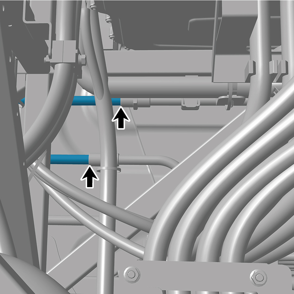
assembly (left).
7
Remove 2 fixing bolts and nuts of the 2 pipe clamps of the
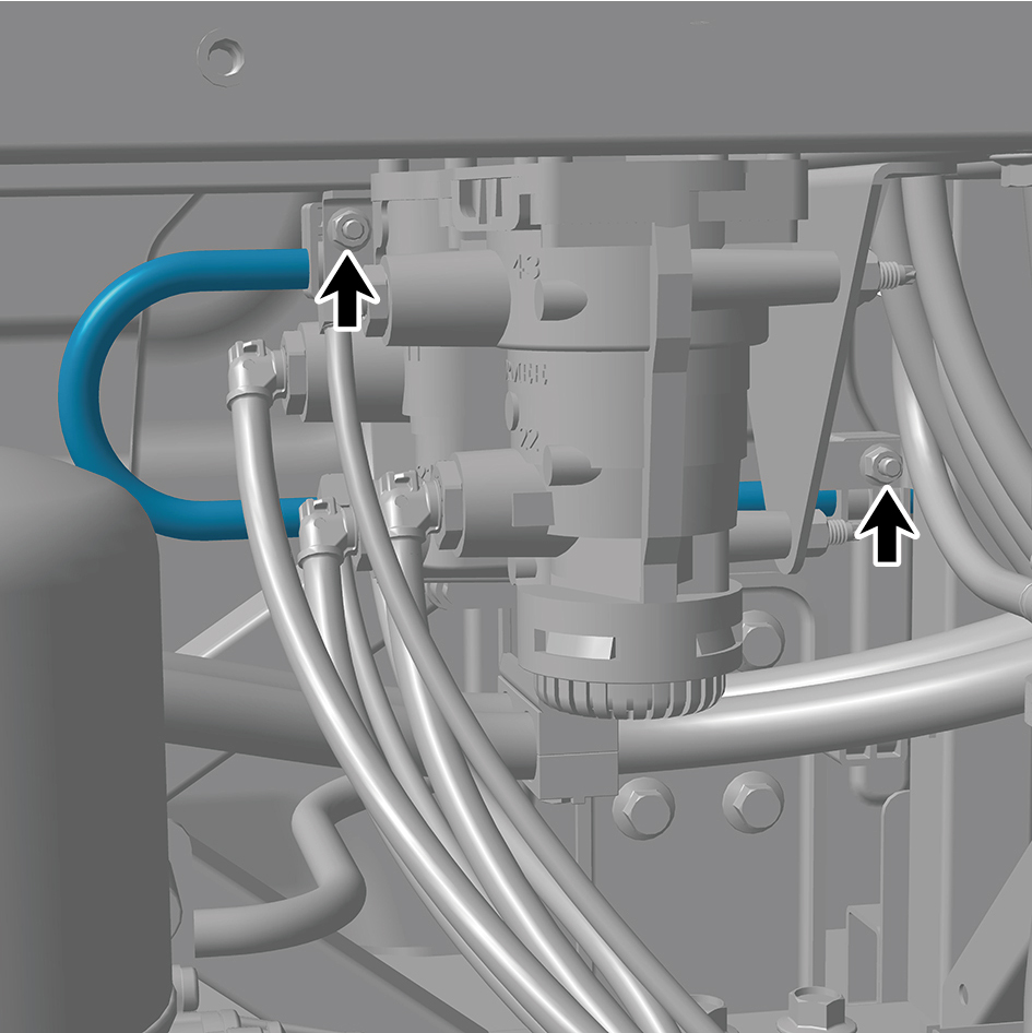
air compressor steel pipe assembly (left).
8
Remove the air compressor steel pipe assembly (left).
Installation Procedures
1
Move the air compressor steel pipe assembly (left) to the
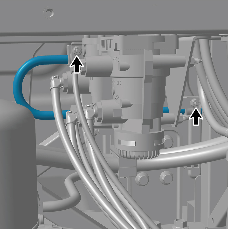
mounting position.
2
Install 2 fixing bolts and nuts of the 2 pipe clamps of the
air compressor steel pipe assembly (left).
Torque: 22 +/- 3.5 (ft lbs)
3
Connect 2 joints of the air compressor steel pipe
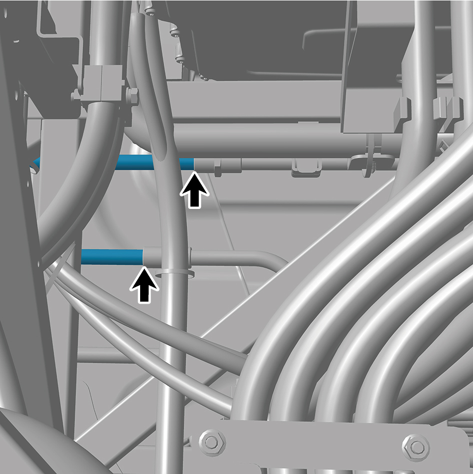
assembly (left).
4
Install the left charging cover plate assembly.
5
Install the left deflector lower body.
6
Install the back integrated bracket middle cover plate
assembly.
7
Install the back integrated bracket side cover plate
assembly (left).
8.17.1.10 Replacement of Air Filter Element
Removal Procedures
1
Release air pressure from the brake system.
2
Open the door.
3
Open the front flip cover plate.
4
Disconnect the battery negative cable.
caution
power down the high-voltage system before
disconnecting the negative pole of the storage
battery.
5
Remove the back integrated bracket side cover plate
assembly (left).
6
Remove the back integrated bracket side cover plate
assembly (right).
7
Remove the back integrated bracket middle cover plate
assembly.
8
Remove the air filter assembly.
9
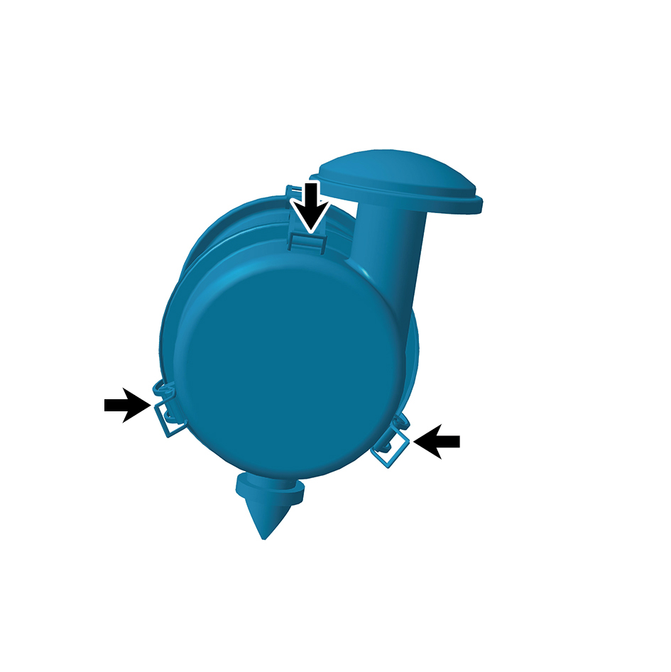
Disengage 3 clips of the air filter element.
10
Remove the air filter element.
Installation Procedures
1
Move the air filter element to the mounting position.
2
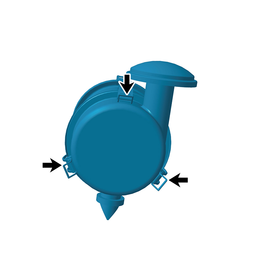
Install 3 clips of the air filter element.
3
Install the air filter assembly.
4
Install the back integrated bracket middle cover plate
assembly.
5
Install the back integrated bracket side cover plate
assembly (right).
6
Install the back integrated bracket side cover plate
assembly (left).
7
Connect the battery negative cable.
8
Close the front flip cover plate.
9
Close the door.
8.17.1.11 Replacement of Air Filter Element (muffler)
(muffler)
Removal Procedures
1
Release air pressure from the brake system.
2
Open the door.
3
Open the front flip cover plate.
4
Disconnect the battery negative cable.
caution
power down the high-voltage system before
disconnecting the negative pole of the storage
battery.
5
Remove the back integrated bracket side cover plate
assembly (left).
6
Remove the back integrated bracket side cover plate
assembly (right).
7
Remove the back integrated bracket middle cover plate
assembly.
8
Remove the air filter assembly.
9
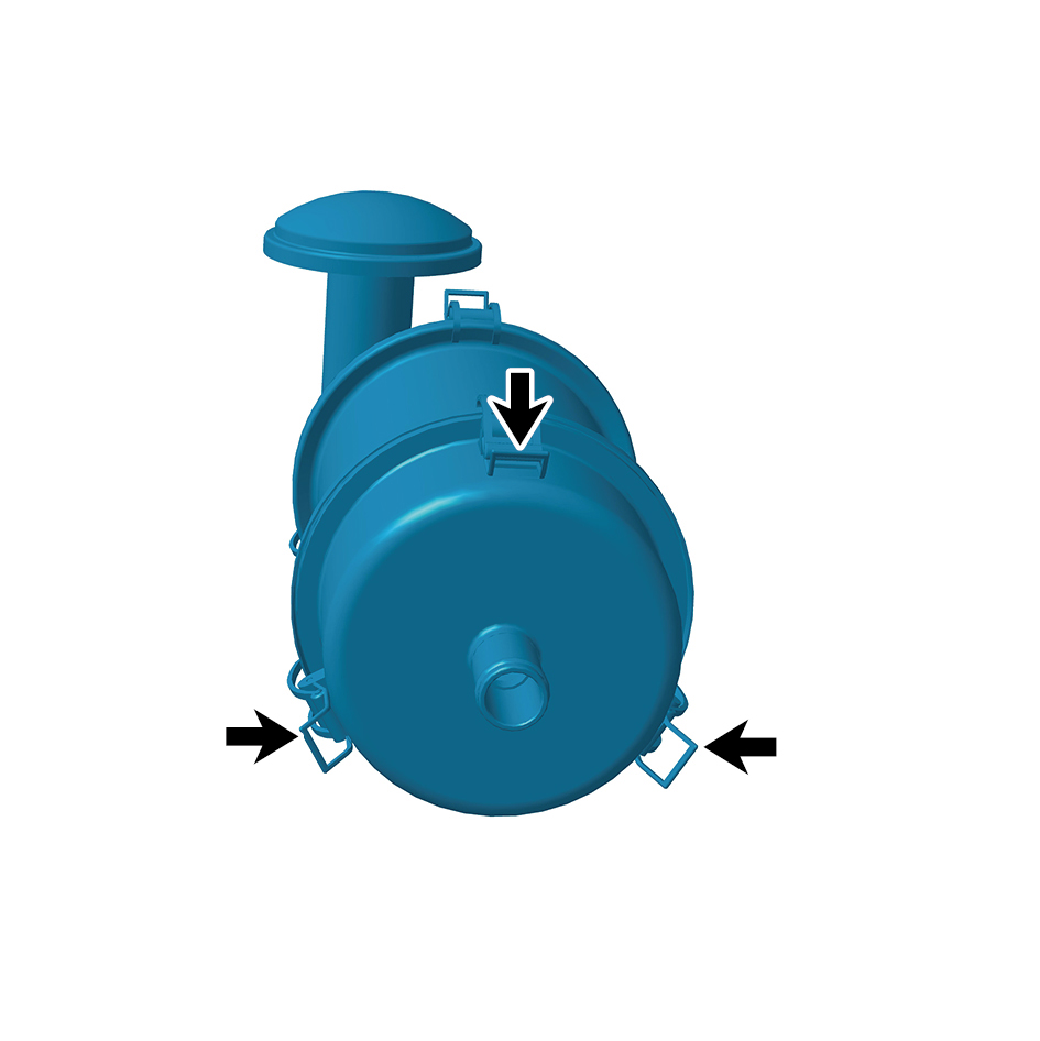
Disengage 3 clips of the air filter element.
10
Remove the air filter element (muffler).
Installation Procedures
1
Move the air filter element (muffler) to the mounting
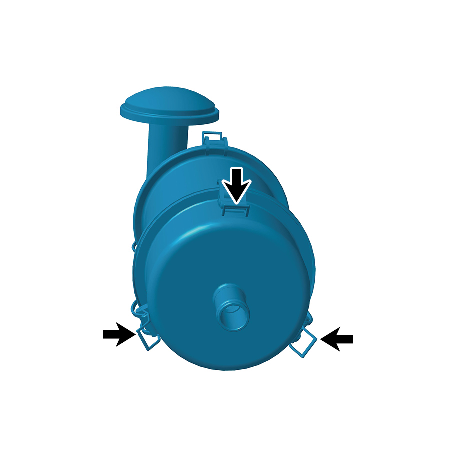
position.
2
Install 3 clips of the air filter element.
3
Install the air filter assembly.
4
Install the back integrated bracket middle cover plate
assembly.
5
Install the back integrated bracket side cover plate
assembly (right).
6
Install the back integrated bracket side cover plate
assembly (left).
7
Connect the battery negative cable.
8
Close the front flip cover plate.
10
Close the door.