← Back to Contents
6 Vehicle Body / 6.16 Side Wall Outer Panel Device | PDF pages 778-787
6.16 Side Wall Outer Panel Device
6.16 Side Wall Outer Panel Device
6.16.1 Specifications
6.16.1.1 Fastener Specifications
Range Of Torque
Fastener Specifications
Specifications
Foot Pounds of Torque (ft lbs)
The fixing bolt connecting the left side
(18.5 +/- 2) ft lbs
M8
bracket and the frame assembly
The fixing bolts connecting the bracket
assembly on the side panel to the frame
(103 +/- 7) ft lbs
M14
assembly
The fixing nut connecting the bracket
assembly on the side panel to the frame
(18.5 +/- 2) ft lbs
M8
assembly
The fixing bolts connecting the left side
panel lower decorative panel installation
(103 +/- 7) ft lbs
M14
frame assembly and the frame
assembly
The fixing bolt connecting the circular
hanging bracket to the lower decorative
(12 - 13) ft lbs
M8
panel body assembly
The fixing bolt connecting the left side
panel assembly and the lower
(3 +/- .75) ft lbs
M6
decorative panel assembly of the left
side panel
6.16.2 Decomposition Diagram
6.16.2.1 Decomposition Diagram
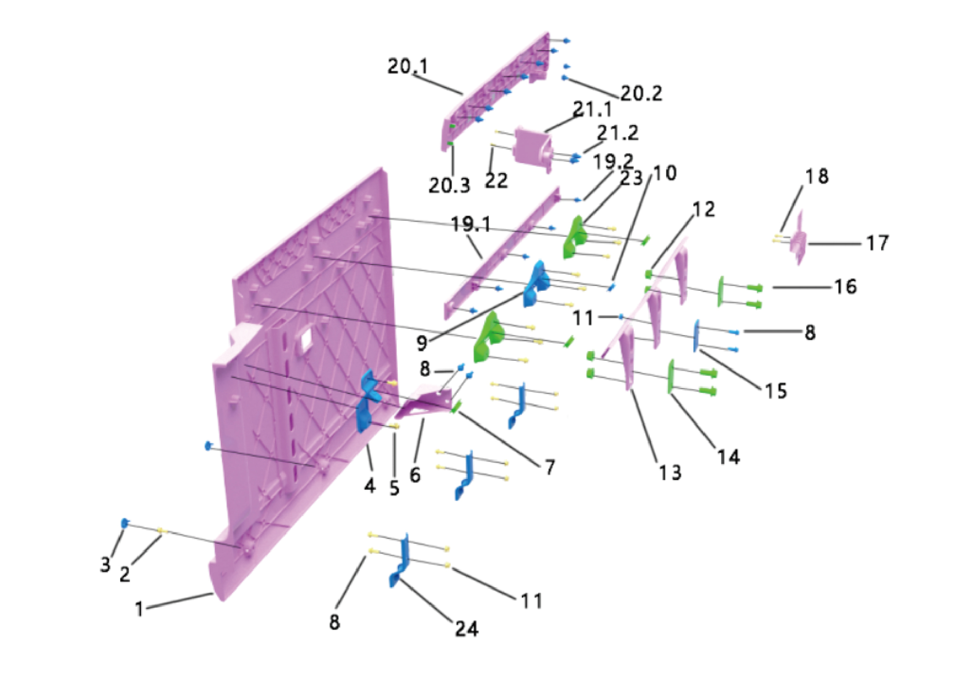
1.
Lower Trim Assy-Rh
15.
Nut Plate 2
2.
Hexagon Head Bolt Assy
16.
Hexagon Flange Bolt
3.
17.
Pulg-Side Skirt Trim
Side Perimeter Left Bezel
4.
18.
Round Positioning Brkt
Hexagon Flange Bolt
5.
19.1.
Hexagon Flange Bolt
Side Enclosure Decorative Strip 3
6.
19.2.
Plastic Buckle
Front Munting Bracket of Left Side Enclosure
7.
20.1.
Rubber Cover 1
Cover Plate of Right Side Enclosure Slide Rail
8.
20.2.
Hexagon Flange Bolt
Plastic Buckle
9.
Round Mounting Brkt
20.3.
Type A Buckle
10.
21.1.
Rubber Cover 2
End Cover Plate of Right Side Enclosure Slide Rail
11.
Hexagon Flange Nut
21.2.
Plastic Buckle
12.
Hexagon Flange Nut
22.
Cross Recessed Pan Head Machine Screw
13.
23.
Upr Brkt Assy3–Side Pn1
Brkt-Square Mounting
14.
Nut Plate 1
24.
Brkt-Skrit Lower
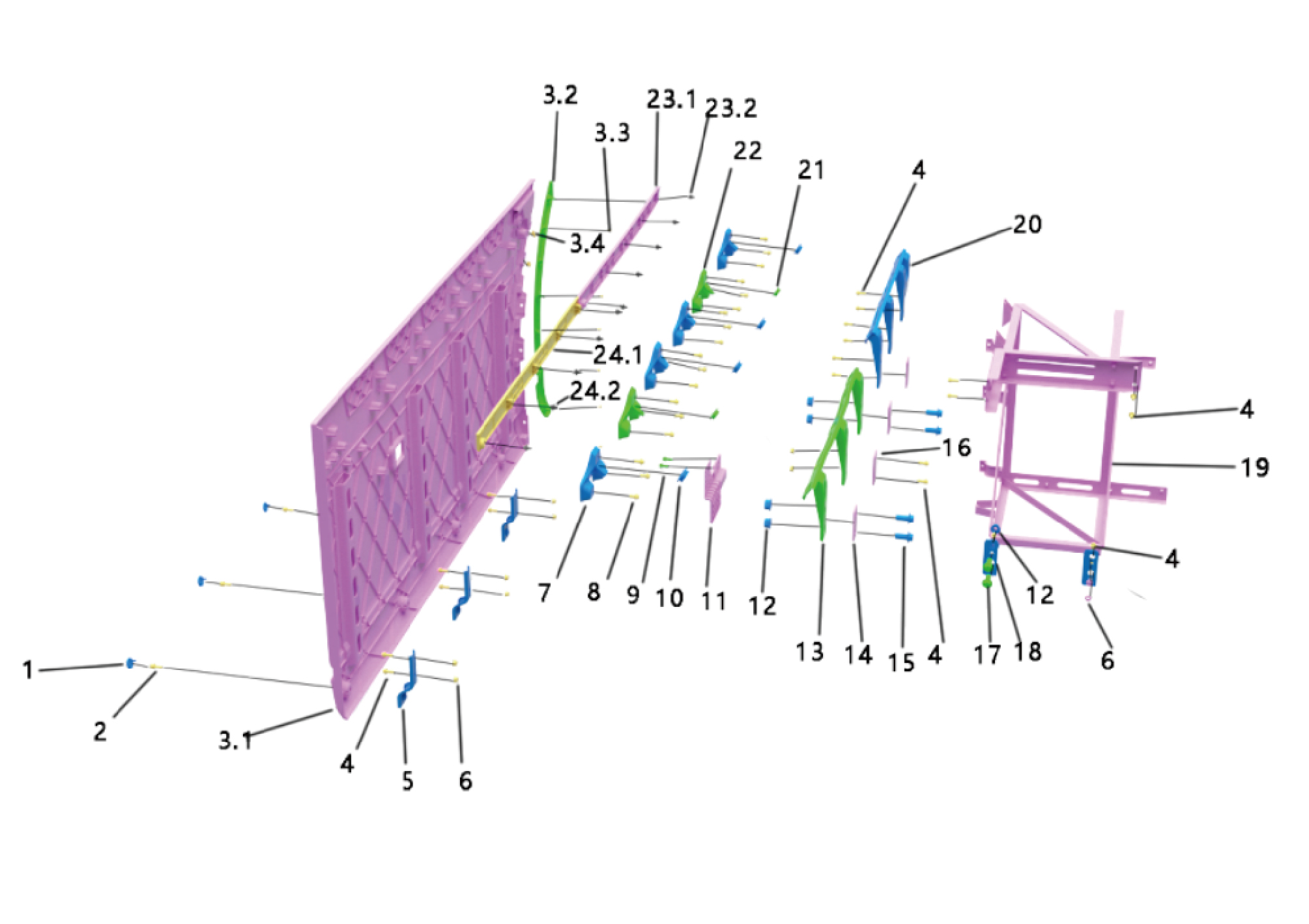
1.
13.
Pulg-Side Skirt Trim
Brkt Assy 1-Side Perimeter Mounted
2.
Hexagon Head Bolt Assy
14.
Nut Plate 1
3.1.
15.
Hexagon Flange Bolt
Lower Plaque Body Assy-Lh Surround
3.2.
16.
Nut Plate 2
Left Front Wheel Eyebrow
3.3.
17.
Hexagon Flange Bolt
Self-Tapping Screw
3.4.
18.
Type B Leaf Spring Nut
Side Mgt Brkt-Lh
4.
Hexagon Flange Bolt
19.
Lower Trim Mounting Frame Assy_Lh
5.
20.
Brkt-Skrit Lower
Brkt Assy 2-Side Perimeter Mounted
6.
Hexagon Flange Nut
21.
Rubber Cover 2
7.
22.
Round Mounting Brkt
Brkt-Square Mounting
8.
Hexagon Flange Bolt
23.1.
Main Body of Side Enclosure Decorative Strip 1
9.
Hexagon Flange Bolt
23.2.
Plastic Buckle
10.
24.1.
Rubber Cover 1
Main Body of Side Enclosure Decorative Strip 2
11.
24.2.
Plastic Buckle
Side Perimeter Right Bezel
12.
Hexagon Flange Nut
6.16.3 Dismantling and Installation
6.16.3.1 Replacement of the Left Side Sill Trim Panel
Panel
Removal Procedures
1
Disconnect the battery negative cable.
caution
power down the high-voltage system before
disconnecting the negative pole of the storage
battery.
2
Remove the 5 fixing bolts of the fender.
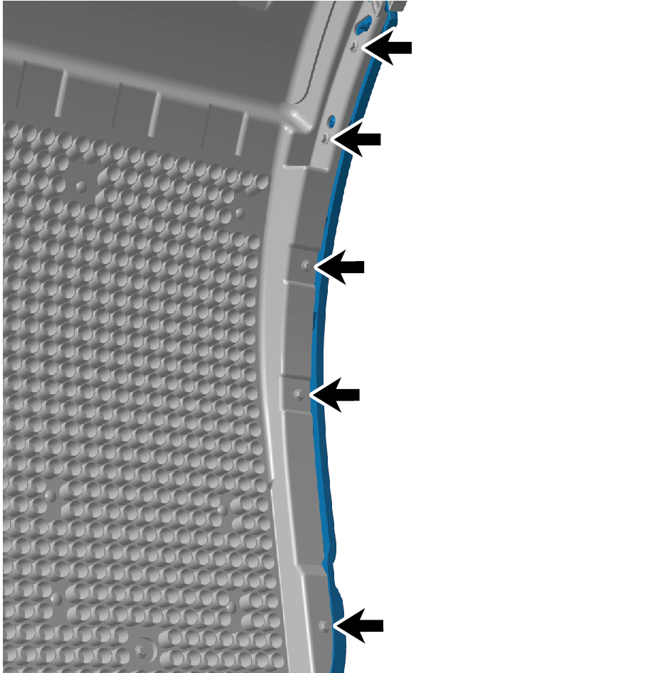
3
Remove the 4 plugs of the left side sill trim panel.
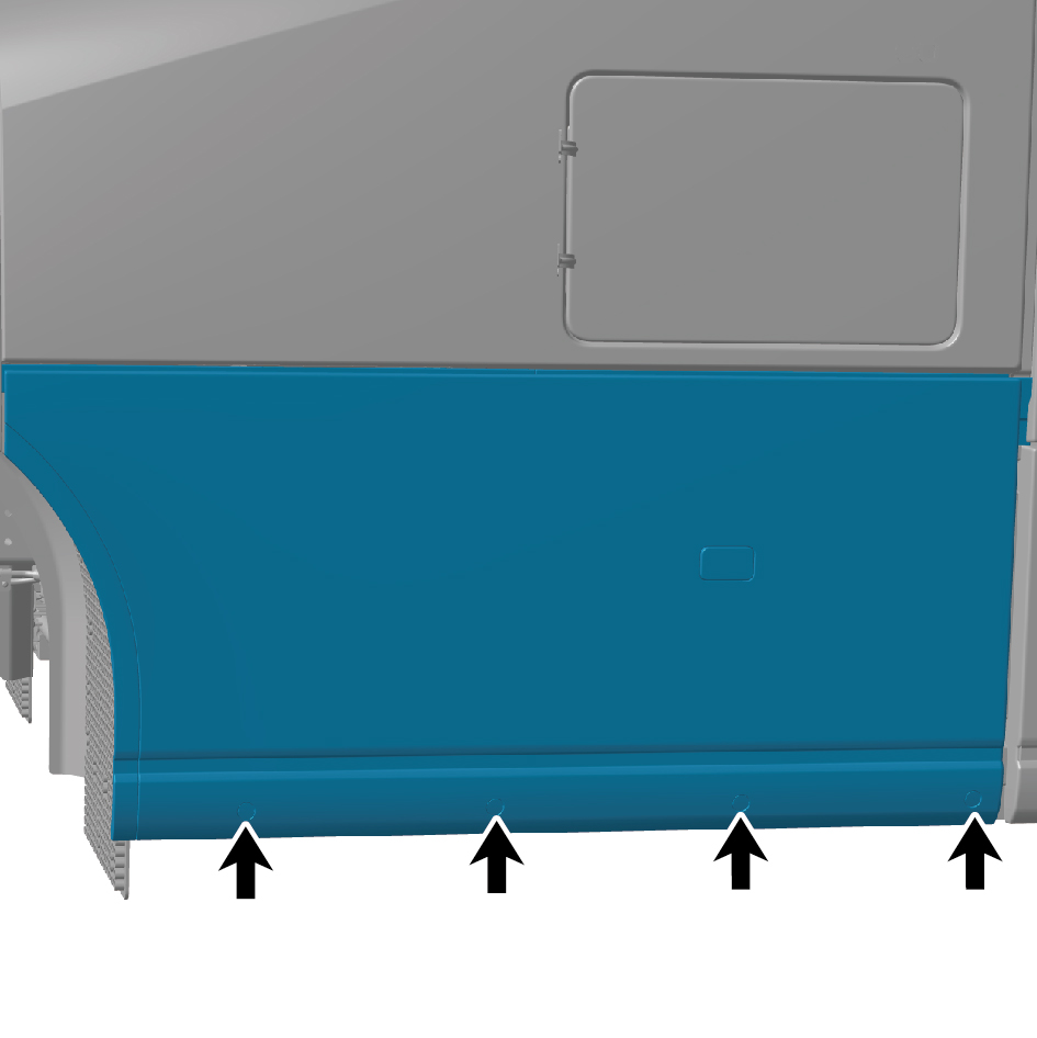
4
Remove the 4 fixing bolts of the left side sill trim panel,
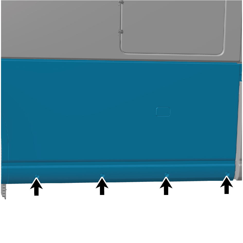
disconnect the wiring harness connector, and take off the
left side sill trim panel.
caution
Pull the 3 pull cables from the inside of the side sill,
and remove the left side sill trim panel after
unlocking the locking mechanism.
When pulling the cables, an assistant shall support
the left side sill trim panel to prevent personal injury
caused by falling.
Installation Procedures
1
Move the left side sill trim panel to the installation position,
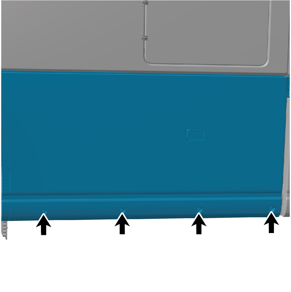
connect the wiring harness connector, and install the 4
fixing bolts of the left side sill trim panel.
caution
The harness is firmly connected following the
principal of "insert until a click is heard for
confirmation".
2
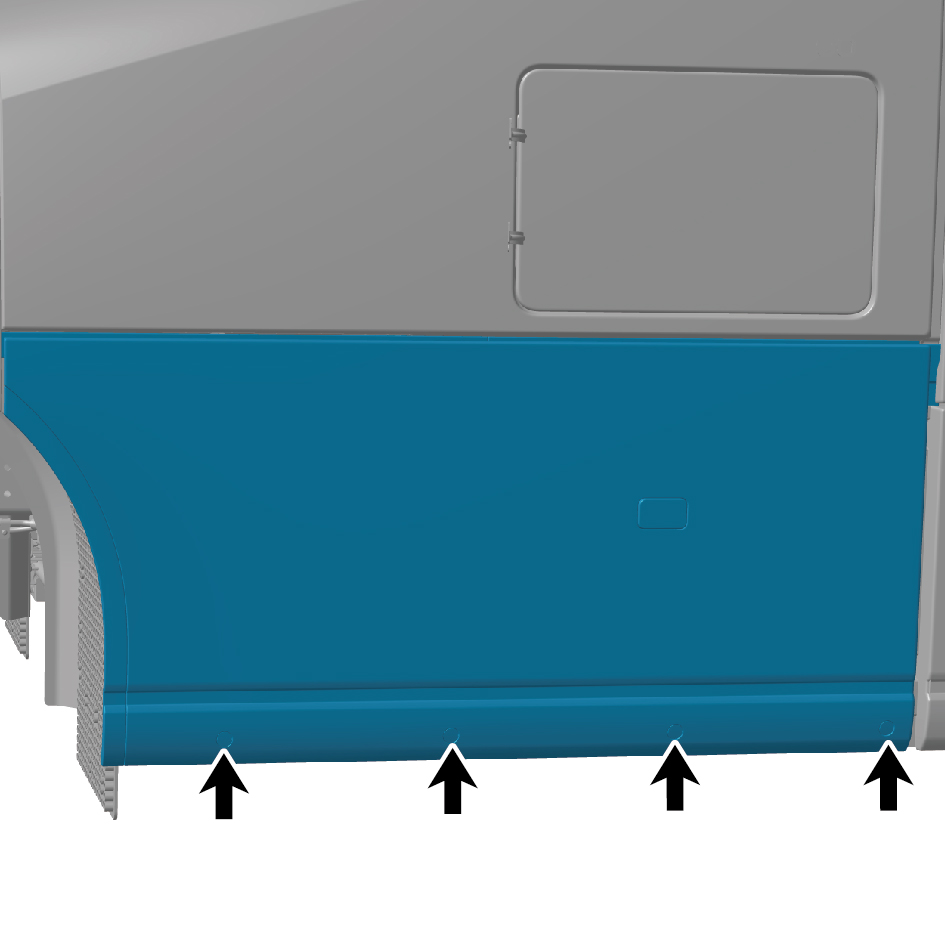
Install the 4 plugs of the left side sill trim panel.
3
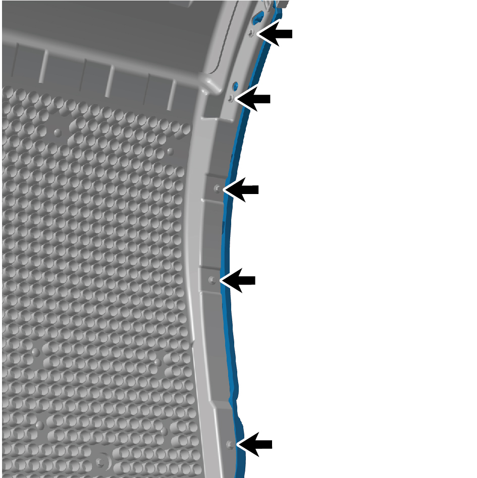
Install the 5 fixing bolts of the fender.
4
Connect the battery negative cable.
6.16.3.2 Replacement of the Right Side Sill Trim Panel
Trim Panel
Removal Procedures
1
Disconnect the battery negative cable.
caution
power down the high-voltage system before
disconnecting the negative pole of the storage
battery.
2
Remove the 2 fixing bolts of the right side sill trim panel
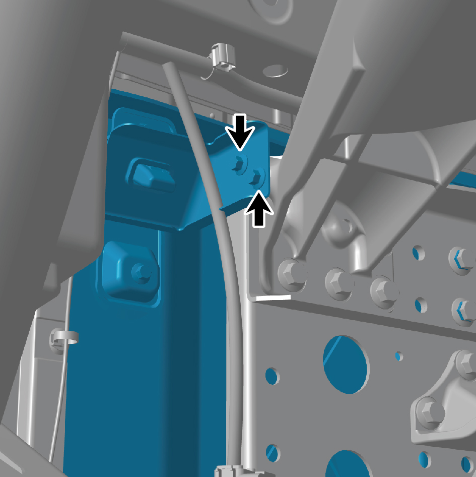
from the back.
3
Remove the 3 plugs of the right side sill trim panel.
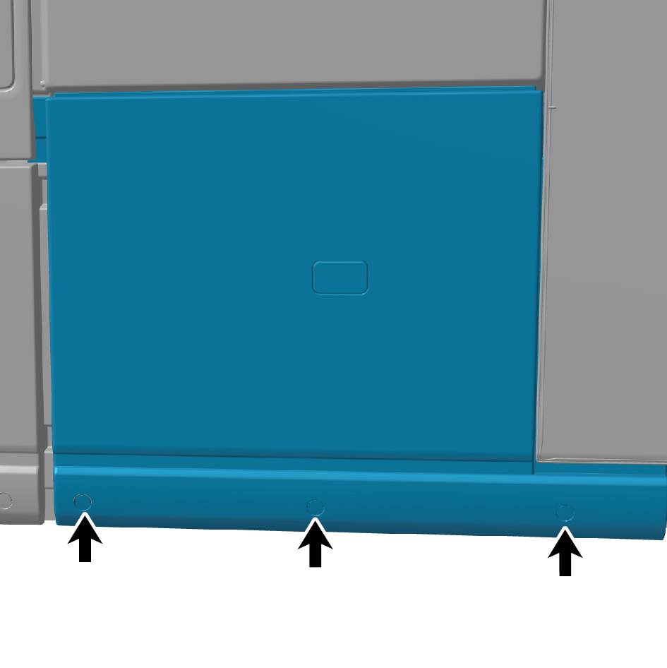
4
Remove the 3 fixing bolts of the right side sill trim panel,
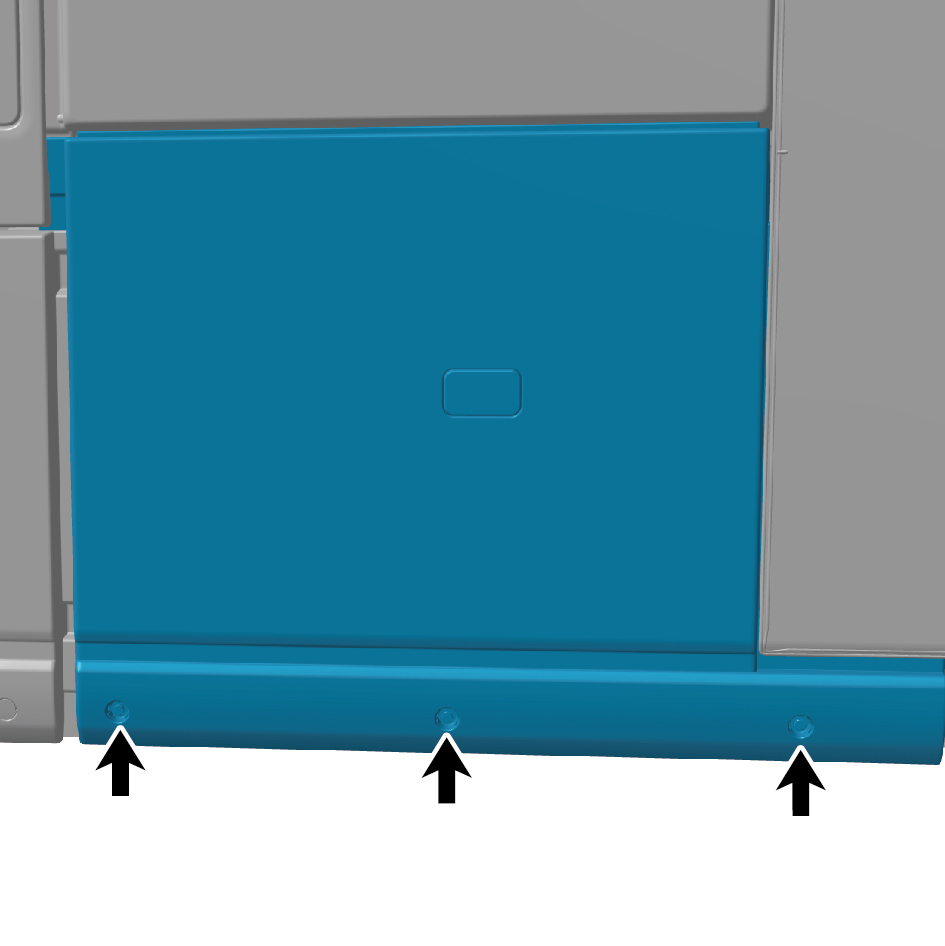
disconnect the wiring harness connector, and take off the
right side sill trim panel horizontally along the upper right
direction.
Installation Procedures
1
Move the right side sill trim panel to the installation
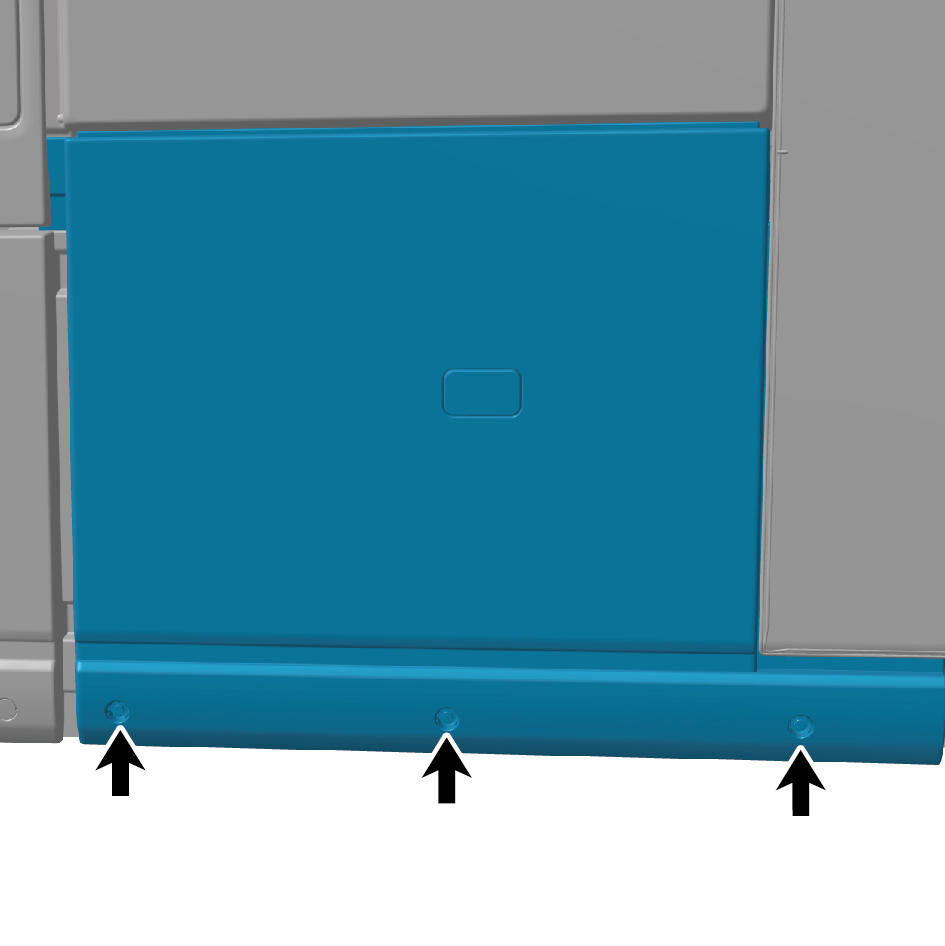
position, connect the wiring harness connector, and install
the 3 fixing bolts of the right side sill trim panel.
caution
The harness is firmly connected following the
principal of "insert until a click is heard for
confirmation".
2
Install the 3 plugs of the right side sill trim panel.
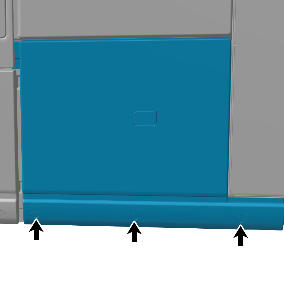
3
Install the 2 fixing bolts of the right side sill trim panel from
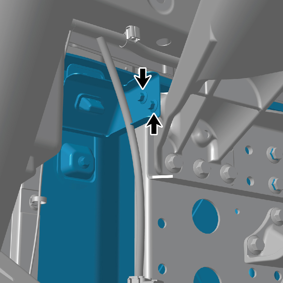
the back.
4
Connect the battery negative cable.