← Back to Contents
4 New Energy Vehicle Components / 4.1 Integrated E-axle Device | PDF pages 75-188
4.1 Integrated E-axle Device
4.1 Integrated E-axle Device
4.1.1 Quality Warranty Statement
4.1.1.1 Emission Quality Warranty Statement
– For emissions-related warranty (5 years or 100,000
miles) under “powertrain” list main components that need to
be covered – motor, inverter, HV battery charging system,
batteries and thermal management.
– The emission-related warranty covers all components
whose failure would increase a vehicle's emissions of air
conditioning refrigerants.
4.1.2 specifications
4.1.2.1 Fastener Specifications
Range Of Torque
Specifications
Fastener name
Metric System(ft-lb)
The grounding wire fixing bolt
connecting the integrated axle and the
(11 ft-lb +/- .5 ft-lb) ft-lb
M8
frame assembly
4.1.2.2 Technical Parameters
Drive Motor
Item
General Parameters
Jiangsu Maxwell Industries Co., Ltd.
Manufacturer
Type
Permanent magnetic synchronous motor
Continuous power
170kW
Peak power
260kW
Continuous torque
184 lb·ft
Peak torque
405lb·ft
Speed range
0-11,000 r/min
Insulation grade
Cooling method
Water cooling
Protection rating
IP67
Weight
60 kg
System efficiency
97.4%
4.1.3 Decomposition Diagram
4.1.3.1 Decomposition Diagram
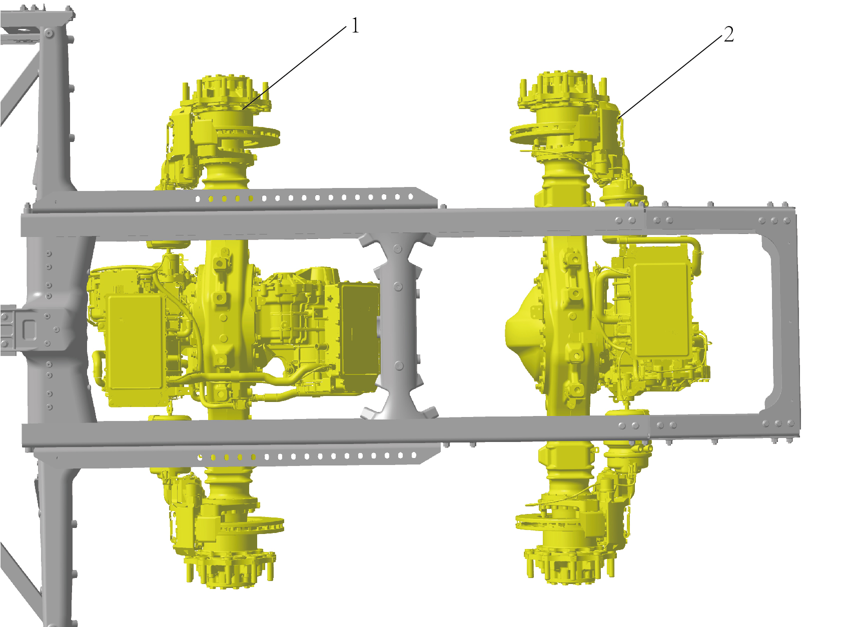
1.
Axle Electric Drive Assy
2.
Axle Electric Drive Assy
4.1.4 Inspect
4.1.4.1 Inspection of Electric Drive System
Before starting the vehicle, check whether the relevant data
displayed on the instrument cluster is normal. If the data is
abnormal, do not drive the vehicle. Instead, record the system
fault type and related data, and report the information to the
Windrose authorized service station.
caution
If the high voltage battery or motor system fails, please
contact a Windrose authorized service station for repair
in time.
4.1.5 System Schematic Diagram
4.1.5.1 Electrical Schematic Diagram
4.1.6 Diagnostic Information and Steps
4.1.6.1 Diagnosis Description
Before diagnosing faults in the integrated axle device, it is important to understand and familiarize oneself with the working
principle of the integrated axle device, and then begin system diagnosis. This will help determine the correct fault diagnosis steps
when a fault occurs, and more importantly, it will help determine whether the situation described by the customer belongs to
normal operation. Any fault diagnosis of integrated axle devices should start with routine inspection, guiding maintenance
personnel to take the next logical step for fault diagnosis. Understanding and correctly using the diagnostic process can shorten
the diagnosis time and avoid misjudgment of faulty parts.
4.1.6.2 Routine Inspection
• Check for aftermarket installation devices that may affect the operation of the integrated axle device system, ensuring that
these devices do not affect the operation of the integrated axle device system.
• Inspect system components that are easily accessible or visible to make sure they are not visibly damaged or have conditions
that could cause failure.
4.1.6.3 DTC Confirmation
1.Connect the diagnostic instrument to the diagnostic interface, read and record the DTC, and then clear the DTC.
2. Restart the vehicle.
3. Read the fault code of the control system again to confirm whether the system has a fault code output.
– Yes:Diagnose based on the output fault code.
– No:Perform intermittent fault checks, refer to Inspection Of Intermittent Fault
4.1.6.4 Inspection Of Intermittent Faults
caution
•
Clear DTC.
•
Conduct mock tests.
•
Check and shake the wiring harness, connector box terminals.
When the fault cannot be confirmed by DTC inspection, the fault phenomenon only occasionally occurs in use. This should
confirm all circuits and components that may cause the failure. In many cases, the fault location can be quickly and efficiently
identified by performing the basic checks shown in the flowchart below. Especially for faults such as poor contact of wiring
harness connectors. Fault Definition: This fault is not currently occurring, but historical DTC records indicate that this fault has
occurred. Or the customer has reported the fault to be repaired, but because the fault is not related to the DTC, the fault
symptoms cannot be reproduced at this time.
Diagnostic Steps:
Step 1
Check the battery voltage.
A.
Perform vehicle power-up operation.
B.
Measure the voltage of the battery.
C.
According to the measured values, the corresponding
diagnostic step is entered.
Result
To Step
22 V - 27.4 V
Yes
Less than 22 V
Check the main battery. Refer to
Inspection Of Main Battery
Yes
Visual physical inspection.
Step 2
Performing this step is an important means to preliminarily
determine the location of the fault:
• Check the wiring harness is damaged, whether there are
wear, broken skin and other faults.
• Check the wiring harness is improperly arranged. It is
strictly forbidden to close the wiring harness to high voltage
or high current devices.
• Check the positive and negative cables of the battery are
connected reliably and whether there are any phenomena
such as looseness, oxidation and corrosion.
Next Step
Step 3
Check the wiring harness, connectors.
A.
Many intermittent failures are caused by wire harness
and connector movement caused by vibration, twisting,
uneven road or component operation.
B.
If the circuit resistance is too high, the component may
not work properly. Use the diagnostic instrument to
force the actuator to drive. If it can't work normally,
Check the relevant circuit has line faults such as
excessive resistance.
Next Step
Step 4
Reproduce the fault and record the data of the control unit with the instrument.
A.
Connect the vehicle fault diagnosis instrument, and use
the data recording function of the fault diagnosis
instrument to record the data when intermittent faults
occur on the road test vehicle. After pressing the button
of the vehicle data logger, the control module data can
be recorded in the event of intermittent failure, which
can be used to identify the failure location.
B.
Another diagnostic method is to connect the digital
multimeter to the suspicious circuit while the vehicle is
running. The abnormal reading value of the digital
multimeter may indicate the fault location.
Next Step
Step 5
The fault LED illuminates intermittently, but the system has no fault code set.
The following conditions may cause the fault LED to
illuminate intermittently, but the system will not set a DTC:
• Electromagnetic interference caused by abnormally
working relays, solenoid valves or switches controlled by
the control module.
• Accessories that are not original or after-market, such as
car phones, alarms, lights or radios, are not installed
correctly.
• The fault indicator control circuit is intermittently shorted to
ground.
• The control module ground point is loose.
Next Step
Step 6
Other checks.
Check the charging system for the following conditions:
• Is the output voltage of the high and low voltage charging
system correct? If the DCDC1 output voltage is not around
27.5 V and the DCDC2 output voltage is not around 30.5 V,
repair the charging system.
Next Step
Step 7
Go to the fault symptom table.
4.1.6.5 List Of Diagnostic Trouble Codes (DTCs)
MCU1
Fault Description
Exclusion Method
Fault Code
Supply Voltage Too High
B111717
Refer to MCU1 Power Fault
Supply Voltage Too Low
B111716
VDC Signal checksum Fault
P226500
VDC Signal rollingcounter Fault
P226600
U012287
Lost Communication With VDC
Refer to MCU1 Communication Fault
U015687
Lost Communication With CDCU
U019887
Lost Communication With T-BOX
U008E88
CAN Bus Off
SiC Temperature Sensor "U" Circuit
P222200
short to ground
SiC Temperature Sensor "U" Circuit
P222300
short to battery or open
Refer to MCU1 Internal Fault
SiC Temperature Sensor "V" Circuit
P222400
short to ground
SiC Temperature Sensor "V" Circuit
P222500
short to battery or open
Fault Description
Exclusion Method
Fault Code
SiC Temperature Sensor "V" Circuit
P222600
short to ground
SiC Temperature Sensor "V" Circuit
P222700
short to battery or open
SiC Temperature Sensor ,Any Two
P222800
Phase electronic failure
Drive Motor "A" Temperature Sensor
P222B00
Circuit short to ground or open
Drive Motor "A" Temperature Sensor
P222C00
Circuit short to battery
Drive Motor "B" Temperature Sensor
P222D00
Circuit short to ground or open
Drive Motor "B" Temperature Sensor
P222E00
Circuit short to battery
Drive Motor "A" and "B" Temperature
P222F00
Sensor compare failure
Drive Motor "A" and "B" Temperature
P223000
Sensor Circuit electrical failure
Drive Motor Stalling Fault
P223100
Coolant Temperature Sensor Circuit
P223300
short to ground
Coolant Temperature Sensor Circuit
P223400
short to battery or open
Dreating Due to Drive Motor OverSpeed
P223500
Drive Motor OverSpeed Fault
P223600
Function Safety Speed Monitoring Faul
P223700
High Bridge Driver Fault
P223800
Low Bridge Driver Fault
P223900
CAN Link Chip Fault
P223A00
SBC Chip fault
P223B00
Current sensor Power supply voltage
P223C00
out of range
Power supply fault of driver board 5V out
P223D00
of range
SiC driver IC power supply voltage out
P223E00
of range
Function Safety internal Low
P223F00
PowerSupply Monitoring Fault
A/D Processing Performance fault
P224000
Fault Description
Exclusion Method
Fault Code
P224100
EEPROM Fault
MCU Unexpected Restart fault
P224200
P224300
MCU Self-Check fault
P224400
Shutdown Path Check fault
Inverter Performance Unexpected
P224500
operation
Torque difference between function
P224600
Safety layer and QM out of range fault
Torque difference between function
Safety layer and Requested out of
P224700
range fault
Enter ASC State Due to Back-EMF
P224800
voltage too high
P226700
Drive Motor Zero Position Not Learned
Resolver QM SIN/COS Signal out of
P226800
range Fault
Resolver QM EXC Signal amplitude out
P226900
of range Fault
Resolver FUSA EXC Signal amplitude
P227000
out of range Fault
Resolver FUSA SIN/COS Signal out of
P227100
range Fault
Current timestamp and Angle
P227200
timestampt Check Fault
L1 Electrical angle and Electrical angle
P227300
Check Fault
Resolver SIN and COS Sum of squares
P227400
Check Fault
High Bridge Driver INTA Fault
P227500
High Bridge Driver INTB Fault
P227600
Low Bridge Driver INTA Fault
P227700
Low Bridge Driver INTB Fault
P227800
Dreating Due to SiC Over temperature
P222000
SiC Overtemperature
P222100
Dreating due to Drive Motor Over
P222900
Refer to MCU1 Overheating Fault
temperature
Drive Motor Overtemperature
P222A00
Dreating Due to Coolant Over
P223200
temperature
Fault Description
Exclusion Method
Fault Code
Active Discharge time-out
P224900
Dreating Due to HVDC UnderVoltage
P224A00
HVDC UnderVoltage
P224B00
HVDC "A" Inverter Voltage Sensor
P224C00
Circuit voltage out of range
HVDC "B" Inverter Voltage Sensor
P224D00
Circuit voltage out of range
Function Safety HVDC Monitoring Fault
P224E00
Dreating Due to HVDC OverVoltag
P224F00
HVDC Voltage above SW threshold
P225000
HVDC Voltage above HW threshold
P225100
Drive Motor "U" Current value above
P225200
SW threshold
Drive Motor "V" Current value above
P225300
SW threshold
Drive Motor "W" Current value above
P225400
SW threshold
Drive Motor "U/V/W" Current value
P225500
above HW threshold
Refer to MCU1 High Voltage Circuit
Drive Motor "U"Phase Circuit open Fault
P225600
Fault
Drive Motor "V“Phase Circuit open Fault
P225700
Drive Motor "W"Phase Circuit open
P225800
Fault
Drive Motor "U/V/W" Phase Current
P225900
Sum Check above threshold Fault
Drive Motor "U" Phase Current Offset
P225A00
Exceeded Learning Limit
Drive Motor "V" Phase Current Offset
P225B00
Exceeded Learning Limit
Drive Motor "W" Phase Current Offset
P225C00
Exceeded Learning Limit
Drive Motor "U" Phase Current Sensor
P225D00
Circuit short to ground or open
Drive Motor "U" Phase Current Sensor
P225E00
Circuit short to battery
Drive Motor "V" Phase Current Sensor
P225F00
Circuit short to ground or open
Drive Motor "V" Phase Current Sensor
P226000
Circuit short to battery
Fault Description
Exclusion Method
Fault Code
Drive Motor "W" Phase Current Sensor
P226100
Circuit short to ground or open
Drive Motor "W" Phase Current Sensor
P226200
Circuit short to battery
Function Safety Current Monitoring
P226300
Fault
P226400
Collision fault
Refer to MCU1 Collision Fault
MCU2
Fault Description
Exclusion Method
Fault Code
Supply Voltage Too High
B111717
Refer to MCU2 Power Fault
Supply Voltage Too Low
B111716
VDC Signal checksum Fault
P236500
VDC Signal rollingcounter Fault
P236600
U012287
Lost Communication With VDC
Refer to MCU2 Communication Fault
U015687
Lost Communication With CDCU
U019887
Lost Communication With T-BOX
U008E88
CAN Bus Off
SiC Temperature Sensor "U" Circuit
P232200
short to ground
SiC Temperature Sensor "U" Circuit
P232300
short to battery or open
SiC Temperature Sensor "V" Circuit
P232400
short to ground
SiC Temperature Sensor "V" Circuit
P232500
short to battery or open
SiC Temperature Sensor "V" Circuit
P232600
short to ground
SiC Temperature Sensor "V" Circuit
Refer to MCU2 Internal Fault
P232700
short to battery or open
SiC Temperature Sensor ,Any Two
P232800
Phase electronic failure
Drive Motor "A" Temperature Sensor
P232B00
Circuit short to ground or open
Drive Motor "A" Temperature Sensor
P232C00
Circuit short to battery
Drive Motor "B" Temperature Sensor
P232D00
Circuit short to ground or open
Drive Motor "B" Temperature Sensor
P232E00
Circuit short to battery
Fault Description
Exclusion Method
Fault Code
Drive Motor "A" and "B" Temperature
P232F00
Sensor compare failure
Drive Motor "A" and "B" Temperature
P233000
Sensor Circuit electrical failure
Drive Motor Stalling Fault
P233100
Coolant Temperature Sensor Circuit
P233300
short to ground
Coolant Temperature Sensor Circuit
P233400
short to battery or open
Dreating Due to Drive Motor OverSpeed
P233500
Drive Motor OverSpeed Fault
P233600
Function Safety Speed Monitoring Faul
P233700
High Bridge Driver Fault
P233800
Low Bridge Driver Fault
P233900
CAN Link Chip Fault
P233A00
SBC Chip fault
P233B00
Current sensor Power supply voltage
P233C00
out of range
Power supply fault of driver board 5V out
P233D00
of range
SiC driver IC power supply voltage out
P233E00
of range
Function Safety internal Low
P233F00
PowerSupply Monitoring Fault
A/D Processing Performance fault
P234000
P234100
EEPROM Fault
MCU Unexpected Restart fault
P234200
P234300
MCU Self-Check fault
P234400
Shutdown Path Check fault
Inverter Performance Unexpected
P234500
operation
Torque difference between function
P234600
Safety layer and QM out of range fault
Torque difference between function
Safety layer and Requested out of
P234700
range fault
Enter ASC State Due to Back-EMF
P234800
voltage too high
P236700
Drive Motor Zero Position Not Learned
Fault Description
Exclusion Method
Fault Code
Resolver QM SIN/COS Signal out of
P236800
range Fault
Resolver QM EXC Signal amplitude out
P236900
of range Fault
Resolver FUSA EXC Signal amplitude
P237000
out of range Fault
Resolver FUSA SIN/COS Signal out of
P237100
range Fault
Current timestamp and Angle
P237200
timestampt Check Fault
L1 Electrical angle and Electrical angle
P237300
Check Fault
Resolver SIN and COS Sum of squares
P237400
Check Fault
High Bridge Driver INTA Fault
P237500
High Bridge Driver INTB Fault
P237600
Low Bridge Driver INTA Fault
P237700
Low Bridge Driver INTB Fault
P237800
Dreating Due to SiC Over temperature
P232000
SiC Overtemperature
P232100
Dreating due to Drive Motor Over
P232900
Refer to MCU2 Overheating Fault
temperature
Drive Motor Overtemperature
P232A00
Dreating Due to Coolant Over
P233200
temperature
Active Discharge time-out
P234900
Dreating Due to HVDC UnderVoltage
P234A00
HVDC UnderVoltage
P234B00
HVDC "A" Inverter Voltage Sensor
P234C00
Circuit voltage out of range
HVDC "B" Inverter Voltage Sensor
P234D00
Refer to MCU2 High Voltage Circuit
Circuit voltage out of range
Fault
Function Safety HVDC Monitoring Fault
P234E00
Dreating Due to HVDC OverVoltag
P234F00
HVDC Voltage above SW threshold
P235000
HVDC Voltage above HW threshold
P235100
Drive Motor "U" Current value above
P235200
SW threshold
Fault Description
Exclusion Method
Fault Code
Drive Motor "V" Current value above
P235300
SW threshold
Drive Motor "W" Current value above
P235400
SW threshold
Drive Motor "U/V/W" Current value
P235500
above HW threshold
Drive Motor "U"Phase Circuit open Fault
P235600
Drive Motor "V“Phase Circuit open Fault
P235700
Drive Motor "W"Phase Circuit open
P235800
Fault
Drive Motor "U/V/W" Phase Current
P235900
Sum Check above threshold Fault
Drive Motor "U" Phase Current Offset
P235A00
Exceeded Learning Limit
Drive Motor "V" Phase Current Offset
P235B00
Exceeded Learning Limit
Drive Motor "W" Phase Current Offset
P235C00
Exceeded Learning Limit
Drive Motor "U" Phase Current Sensor
P235D00
Circuit short to ground or open
Drive Motor "U" Phase Current Sensor
P235E00
Circuit short to battery
Drive Motor "V" Phase Current Sensor
P235F00
Circuit short to ground or open
Drive Motor "V" Phase Current Sensor
P236000
Circuit short to battery
Drive Motor "W" Phase Current Sensor
P236100
Circuit short to ground or open
Drive Motor "W" Phase Current Sensor
P236200
Circuit short to battery
Function Safety Current Monitoring
P236300
Fault
P236400
Collision fault
Refer to MCU2 Collision fault
MCU3
Fault Description
Exclusion Method
Fault Code
Supply Voltage Too High
B111717
Refer to MCU3 Power Fault
Supply Voltage Too Low
B111716
VDC Signal checksum Fault
P246500
Refer to MCU3 Communication Fault
VDC Signal rollingcounter Fault
P246600
Fault Description
Exclusion Method
Fault Code
U012287
Lost Communication With VDC
U015687
Lost Communication With CDCU
U019887
Lost Communication With T-BOX
U008E88
CAN Bus Off
SiC Temperature Sensor "U" Circuit
P242200
short to ground
SiC Temperature Sensor "U" Circuit
P242300
short to battery or open
SiC Temperature Sensor "V" Circuit
P242400
short to ground
SiC Temperature Sensor "V" Circuit
P242500
short to battery or open
SiC Temperature Sensor "V" Circuit
P242600
short to ground
SiC Temperature Sensor "V" Circuit
P242700
short to battery or open
SiC Temperature Sensor ,Any Two
P242800
Phase electronic failure
Drive Motor "A" Temperature Sensor
P242B00
Circuit short to ground or open
Drive Motor "A" Temperature Sensor
P242C00
Circuit short to battery
Refer to MCU3 Internal Fault
Drive Motor "B" Temperature Sensor
P242D00
Circuit short to ground or open
Drive Motor "B" Temperature Sensor
P242E00
Circuit short to battery
Drive Motor "A" and "B" Temperature
P242F00
Sensor compare failure
Drive Motor "A" and "B" Temperature
P243000
Sensor Circuit electrical failure
Drive Motor Stalling Fault
P243100
Coolant Temperature Sensor Circuit
P243300
short to ground
Coolant Temperature Sensor Circuit
P243400
short to battery or open
Dreating Due to Drive Motor OverSpeed
P243500
Drive Motor OverSpeed Fault
P243600
Function Safety Speed Monitoring Faul
P243700
High Bridge Driver Fault
P243800
Low Bridge Driver Fault
P243900
Fault Description
Exclusion Method
Fault Code
CAN Link Chip Fault
P243A00
SBC Chip fault
P243B00
Current sensor Power supply voltage
P243C00
out of range
Power supply fault of driver board 5V out
P243D00
of range
SiC driver IC power supply voltage out
P243E00
of range
Function Safety internal Low
P243F00
PowerSupply Monitoring Fault
A/D Processing Performance fault
P244000
P244100
EEPROM Fault
MCU Unexpected Restart fault
P244200
P244300
MCU Self-Check fault
P244400
Shutdown Path Check fault
Inverter Performance Unexpected
P244500
operation
Torque difference between function
P244600
Safety layer and QM out of range fault
Torque difference between function
Safety layer and Requested out of
P244700
range fault
Enter ASC State Due to Back-EMF
P244800
voltage too high
P246700
Drive Motor Zero Position Not Learned
Resolver QM SIN/COS Signal out of
P246800
range Fault
Resolver QM EXC Signal amplitude out
P246900
of range Fault
Resolver FUSA EXC Signal amplitude
P247000
out of range Fault
Resolver FUSA SIN/COS Signal out of
P247100
range Fault
Current timestamp and Angle
P247200
timestampt Check Fault
L1 Electrical angle and Electrical angle
P247300
Check Fault
Resolver SIN and COS Sum of squares
P247400
Check Fault
High Bridge Driver INTA Fault
P247500
Fault Description
Exclusion Method
Fault Code
High Bridge Driver INTB Fault
P247600
Low Bridge Driver INTA Fault
P247700
Low Bridge Driver INTB Fault
P247800
Dreating Due to SiC Over temperature
P242000
SiC Overtemperature
P242100
Dreating due to Drive Motor Over
P242900
Refer to MCU3 Overheating Fault
temperature
Drive Motor Overtemperature
P242A00
Dreating Due to Coolant Over
P243200
temperature
Active Discharge time-out
P244900
Dreating Due to HVDC UnderVoltage
P244A00
HVDC UnderVoltage
P244B00
HVDC "A" Inverter Voltage Sensor
P244C00
Circuit voltage out of range
HVDC "B" Inverter Voltage Sensor
P244D00
Circuit voltage out of range
Function Safety HVDC Monitoring Fault
P244E00
Dreating Due to HVDC OverVoltag
P244F00
HVDC Voltage above SW threshold
P245000
HVDC Voltage above HW threshold
P245100
Drive Motor "U" Current value above
P245200
SW threshold
Drive Motor "V" Current value above
Refer to MCU3 High Voltage Circuit
P245300
SW threshold
Fault
Drive Motor "W" Current value above
P245400
SW threshold
Drive Motor "U/V/W" Current value
P245500
above HW threshold
Drive Motor "U"Phase Circuit open Fault
P245600
Drive Motor "V“Phase Circuit open Fault
P245700
Drive Motor "W"Phase Circuit open
P245800
Fault
Drive Motor "U/V/W" Phase Current
P245900
Sum Check above threshold Fault
Drive Motor "U" Phase Current Offset
P245A00
Exceeded Learning Limit
Drive Motor "V" Phase Current Offset
P245B00
Exceeded Learning Limit
Fault Description
Exclusion Method
Fault Code
Drive Motor "W" Phase Current Offset
P245C00
Exceeded Learning Limit
Drive Motor "U" Phase Current Sensor
P245D00
Circuit short to ground or open
Drive Motor "U" Phase Current Sensor
P245E00
Circuit short to battery
Drive Motor "V" Phase Current Sensor
P245F00
Circuit short to ground or open
Drive Motor "V" Phase Current Sensor
P246000
Circuit short to battery
Drive Motor "W" Phase Current Sensor
P246100
Circuit short to ground or open
Drive Motor "W" Phase Current Sensor
P246200
Circuit short to battery
Function Safety Current Monitoring
P246300
Fault
P246400
Collision fault
Refer to MCU3 Collision Fault
MCU4
Fault Description
Exclusion Method
Fault Code
Supply Voltage Too High
B111717
Refer to MCU4 Power Fault
Supply Voltage Too Low
B111716
VDC Signal checksum Fault
P256500
VDC Signal rollingcounter Fault
P256600
U012287
Lost Communication With VDC
Refer to MCU4 Communication Fault
U015687
Lost Communication With CDCU
U019887
Lost Communication With T-BOX
U008E88
CAN Bus Off
SiC Temperature Sensor "U" Circuit
P252200
short to ground
SiC Temperature Sensor "U" Circuit
P252300
short to battery or open
SiC Temperature Sensor "V" Circuit
P252400
short to ground
Refer to MCU4 Internal Fault
SiC Temperature Sensor "V" Circuit
P252500
short to battery or open
SiC Temperature Sensor "V" Circuit
P252600
short to ground
SiC Temperature Sensor "V" Circuit
P252700
short to battery or open
Fault Description
Exclusion Method
Fault Code
SiC Temperature Sensor ,Any Two
P252800
Phase electronic failure
Drive Motor "A" Temperature Sensor
P252B00
Circuit short to ground or open
Drive Motor "A" Temperature Sensor
P252C00
Circuit short to battery
Drive Motor "B" Temperature Sensor
P252D00
Circuit short to ground or open
Drive Motor "B" Temperature Sensor
P252E00
Circuit short to battery
Drive Motor "A" and "B" Temperature
P252F00
Sensor compare failure
Drive Motor "A" and "B" Temperature
P253000
Sensor Circuit electrical failure
Drive Motor Stalling Fault
P253100
Coolant Temperature Sensor Circuit
P253300
short to ground
Coolant Temperature Sensor Circuit
P253400
short to battery or open
Dreating Due to Drive Motor OverSpeed
P253500
Drive Motor OverSpeed Fault
P253600
Function Safety Speed Monitoring Faul
P253700
High Bridge Driver Fault
P253800
Low Bridge Driver Fault
P253900
CAN Link Chip Fault
P253A00
SBC Chip fault
P253B00
Current sensor Power supply voltage
P253C00
out of range
Power supply fault of driver board 5V out
P253D00
of range
SiC driver IC power supply voltage out
P253E00
of range
Function Safety internal Low
P253F00
PowerSupply Monitoring Fault
A/D Processing Performance fault
P254000
P254100
EEPROM Fault
MCU Unexpected Restart fault
P254200
P254300
MCU Self-Check fault
P254400
Shutdown Path Check fault
Fault Description
Exclusion Method
Fault Code
Inverter Performance Unexpected
P254500
operation
Torque difference between function
P254600
Safety layer and QM out of range fault
Torque difference between function
Safety layer and Requested out of
P254700
range fault
Enter ASC State Due to Back-EMF
P254800
voltage too high
P256700
Drive Motor Zero Position Not Learned
Resolver QM SIN/COS Signal out of
P256800
range Fault
Resolver QM EXC Signal amplitude out
P256900
of range Fault
Resolver FUSA EXC Signal amplitude
P257000
out of range Fault
Resolver FUSA SIN/COS Signal out of
P257100
range Fault
Current timestamp and Angle
P257200
timestampt Check Fault
L1 Electrical angle and Electrical angle
P257300
Check Fault
Resolver SIN and COS Sum of squares
P257400
Check Fault
High Bridge Driver INTA Fault
P257500
High Bridge Driver INTB Fault
P257600
Low Bridge Driver INTA Fault
P257700
Low Bridge Driver INTB Fault
P257800
Dreating Due to SiC Over temperature
P252000
SiC Overtemperature
P252100
Dreating due to Drive Motor Over
P252900
Refer to MCU4 Overheating Fault
temperature
Drive Motor Overtemperature
P252A00
Dreating Due to Coolant Over
P253200
temperature
Active Discharge time-out
P254900
Refer to MCU4 High Voltage Circuit
Dreating Due to HVDC UnderVoltage
P254A00
Fault
HVDC UnderVoltage
P254B00
Fault Description
Exclusion Method
Fault Code
HVDC "A" Inverter Voltage Sensor
P254C00
Circuit voltage out of range
HVDC "B" Inverter Voltage Sensor
P254D00
Circuit voltage out of range
Function Safety HVDC Monitoring Fault
P254E00
Dreating Due to HVDC OverVoltag
P254F00
HVDC Voltage above SW threshold
P255000
HVDC Voltage above HW threshold
P255100
Drive Motor "U" Current value above
P255200
SW threshold
Drive Motor "V" Current value above
P255300
SW threshold
Drive Motor "W" Current value above
P255400
SW threshold
Drive Motor "U/V/W" Current value
P255500
above HW threshold
Drive Motor "U"Phase Circuit open Fault
P255600
Drive Motor "V“Phase Circuit open Fault
P255700
Drive Motor "W"Phase Circuit open
P255800
Fault
Drive Motor "U/V/W" Phase Current
P255900
Sum Check above threshold Fault
Drive Motor "U" Phase Current Offset
P255A00
Exceeded Learning Limit
Drive Motor "V" Phase Current Offset
P255B00
Exceeded Learning Limit
Drive Motor "W" Phase Current Offset
P255C00
Exceeded Learning Limit
Drive Motor "U" Phase Current Sensor
P255D00
Circuit short to ground or open
Drive Motor "U" Phase Current Sensor
P255E00
Circuit short to battery
Drive Motor "V" Phase Current Sensor
P255F00
Circuit short to ground or open
Drive Motor "V" Phase Current Sensor
P256000
Circuit short to battery
Drive Motor "W" Phase Current Sensor
P256100
Circuit short to ground or open
Drive Motor "W" Phase Current Sensor
P256200
Circuit short to battery
Fault Description
Exclusion Method
Fault Code
Function Safety Current Monitoring
P256300
Fault
P256400
Collision fault
Refer to MCU4 Collision Fault
TCU1
Fault Description
Exclusion Method
Fault Code
High battery voltage
B111717
Refer to TCU1 Power Fault
Low battery voltage
B111716
U012287
Communication with VCU was lost
Loss of communication with MCU (TCU
can receive life signals from MCU1-4 on
U012A87
the bus)
Loss of communication with MCU (TCU
can receive life signals from MCU1-4 on
U012B87
the bus)
Refer to TCU1 Communication Fault
Loss of communication with MCU (TCU
can receive life signals from MCU1-4 on
U012D87
the bus)
U008E88
PCAN4 BusOff
CDCUCommunication exception
U012E87
TDWCommunication exception
U012F87
First and second gear position sensor
P270300
open circuit failure
First and second gear position sensor to
P270301
power short circuit fault
First and second gear position sensor to
P270302
ground short-circuit fault
The first and second gear position
P270303
sensor signal exceeds the upper limit
The first and second gear position
P270304
sensor signal exceeds the lower limit
Refer to TCU1 Internal Fault
The output shaft speed sensor is open
P270305
faulty
The output shaft speed sensor short-
P270306
circuits the power supply
The output shaft speed sensor is short
P270307
circuit to the ground
The output shaft speed sensor signal
P270308
exceeds the upper limit
P27031E
Reverse second shift failed
Fault Description
Exclusion Method
Fault Code
Second shift in 1st gear failed
P27031F
Second gear failed
P270320
Shift power supply harness positive and
P270348
negative connection
P270349
Shift actuator stuck
The shift motor current sensor is faulty
P270350
The MCU1 motor has abnormal
P270351
overspeed in the drive gear
The MCU4 motor has abnormal
P270352
overspeed in the drive gear
Velocity ratio anomaly
P270353
P270354
Abnormal shift
Shift motor open circuit fault
P270355
The shift motor is short circuit to the
P270356
power supply
Shift motor to ground short circuit fault
P270357
The 5V power supply to the position
P270358
sensor is abnormal
The 8V power supply to the tachometer
P270359
is abnormal
The temperature of the control board is
P270360
too high
TCU2
Fault Description
Exclusion Method
Fault Code
TCU Power Supply Overvoltage
B111717
Refer to TCU2 Power Fault
TCU Power Supply Undervoltage
B111716
U012287
Communication lost with VCU
Loss of communication with MCU (TCU
can receive life signals from MCU1-4 on
U012A87
the bus)
Loss of communication with MCU (TCU
can receive life signals from MCU1-4 on
U012B87
the bus)
Refer to TCU2 Communication Fault
Loss of communication with MCU (TCU
can receive life signals from MCU1-4 on
U012D87
the bus)
U008E88
PCAN4 BusOff
CDCU communication anomaly
U012E87
TDW communication anomaly
U012F87
Fault Description
Exclusion Method
Fault Code
Open circuit fault in 1st/2nd gear
P670300
position sensor
Short circuit to power supply in 1st/2nd
P670301
gear position sensor
Short circuit to ground in 1st/2nd gear
P670302
position sensor
Signal from 1st/2nd gear position
P670303
sensor exceeds upper limit
Signal from 1st/2nd gear position
P670304
sensor falls below lower limit
Open circuit fault in output shaft speed
P670305
sensor
Output shaft speed sensor short circuit
P670306
to power supply
Output shaft speed sensor short circuit
P670307
to ground
Output shaft speed sensor signal
P670308
exceeds upper limit
Reverse gear secondary engagement
P67031E
failure
Refer to TCU2 Internal Fault
1st gear secondary engagement failure
P67031F
2nd gear secondary engagement failure
P670320
Reversed Polarity in Shift Power Supply
P670348
Harness
P670349
Stuck Shift Actuator
P670350
Shift Motor Current Sensor Failure
MCU1 motor exhibits abnormal
P670351
overspeed in drive mode
MCU4 motor exhibits abnormal
P670352
overspeed in drive mode
Abnormal gear ratio
P670353
Abnormal gear disengagement
P670354
Shift motor open-circuit fault
P670355
Shift motor short-circuit to power supply
P670356
Shift motor short-circuit to ground
P670357
Position sensor 5V power supply
P670358
anomaly
RPM sensor 8V power supply anomaly
P670359
Control board over-temperature fault
P670360
4.1.6.6 MCU1 Power Fault
1.DTC Monitoring Logic
Description
DTC Trigger Conditions
Faulty Part
DTC Code
1. Main battery
Supply Voltage Too
KL30>36V
B111717
2. Low voltage
High
debounce 127count*10ms
charging system
3. Wiring harness
4. Low voltage
KL30<15V
Supply Voltage Too
interface of
B111716
debounce 127count*10ms
Low
electric drive
medium axle
vehicle
2.Circuit Diagram
Smart Junction Box - Chassis
Battery
VDC-1
BDCU-4
B48-26
C4-21
C2-G
C93-97
MCU2-CAN
status feedback H01
Differential lock
Middle and rear axle MCU-KL30 O421
36
I7_B_C
36
I7_C_B
MCU2-CAN-H PH04d
feedback signal H01a
Wake-up call E146a
MCU2-CANL PL04d
Differential lock
TCU-KL30 G2G
C27-17
C27-19
C27-1
C27-13
C27-5
C27-6
E-axle mid axle vehicle low voltage port
C27-20
C27-22
C27-14
C27-15
C27-3
C27-4
MCU Power Supply - Z66
TCU Power supply - Z65
MCU1-CAN-H PH04c
MCU1-CANL PL04c
TCU-CAN-H PH04b
TCU-CANL PL04b
MCU1-CAN
TCU-CAN
G02
3. Diagnostic Steps
Step 1:DTC Confirmation. Refer to DTC Confirmation
Step 2:Routine Inspection. Refer to Routine Inspection
Step 3:Check if there are any other module power fault codes besides MCU1?
Check the main battery. Refer to Inspection Of The Main Battery
– Yes:
Check the low-voltage charging system. Refer to DCDC1 Low-voltage Charging System Fault
Next step
– No:
Step 4:Check the power supply and grounding harness of the low-voltage interface of the electric drive medium axle vehicle.
Step 5:Rewrite the configuration code, reload the software, and upgrade the low-voltage interface of the electric drive mid-axle
vehicle.
Step 6:Replace the low-voltage interface of the electric drive mid axle vehicle. Refer to Replacement Of Integrated axle -
Medium axle
Step 7:Clear and confirm DTC.
4.1.6.7 MCU1 Communication Fault
1.DTC Monitoring Logic
Description
DTC Trigger Conditions
Faulty Part
DTC Code
VDC Signal checksum
VDC_MCU_Msg CheckSum error
P226500
Fault
deboumce 19count*10ms
VDC_MCU_Msg Counter alive error
(The Rolling Counter value changes less than 1 or
VDC Signal
P226600
The Rolling
rollingcounter Fault
Counter value changes more than 5 )
1.Wiring harness
deboumce 19count*10ms
2. Electric drive
Lost Communication
VDC_MCUx_Torque_cmd timeout
mid-axle vehicle
U012287
With VDC
debounce 127count*40ms
low-voltage
interface
HighReTotalVehicleDistance timeout
Lost Communication
U015687
debounce 127count*40ms
With CDCU
Lost Communication
TGW_Hours timeout
U019887
With T-BOX
debounce 127count*40ms
"Bus-off" has been detected by AURIX
U008E88
CAN Bus Off
debounce 32count*10ms
2.Circuit Diagram
Smart Junction Box - Chassis
Battery
VDC-1
BDCU-4
B48-26
C4-21
C2-G
C93-97
MCU2-CAN
status feedback H01
Differential lock
Middle and rear axle MCU-KL30 O421
36
I7_B_C
36
I7_C_B
MCU2-CAN-H PH04d
feedback signal H01a
Wake-up call E146a
MCU2-CANL PL04d
Differential lock
TCU-KL30 G2G
C27-17
C27-19
C27-1
C27-13
C27-5
C27-6
E-axle mid axle vehicle low voltage port
C27-20
C27-22
C27-14
C27-15
C27-3
C27-4
MCU Power Supply - Z66
TCU Power supply - Z65
MCU1-CAN-H PH04c
MCU1-CANL PL04c
TCU-CAN-H PH04b
TCU-CANL PL04b
MCU1-CAN
TCU-CAN
G02
3. Diagnostic Steps
Step 1:DTC Confirmation. Refer to DTC Confirmation
Step 2:Routine Inspection. Refer to Routine Inspection
Step 3:Check the PCAN4 bus communication harness. Refer to Inspection Of PCAN4 Bus Network Integrity
Step 4:Rewrite the configuration code, reload the software, and upgrade the low-voltage interface of the electric drive mid-axle
vehicle.
Step 5:Replace the low-voltage interface of the electric drive mid axle vehicle. Refer to Replacement Of Integrated axle -
Medium axle
Step 6:Clear and confirm DTC.
4.1.6.8 MCU1 Internal Fault
1.DTC Monitoring Logic
Description
DTC Trigger Conditions
Faulty Part
DTC Code
SiC_TEMP_W Duty Value≤17%
SiC Temperature
deboumce 127count*10ms
Sensor "U" Circuit
P222200
if collect SiCTEMP short to Power/GND,The value of
short to ground
this sensor is not used as a temperature strategy
SiC_TEMP_W Duty Value≥89.4%
SiC Temperature
deboumce 127count*10ms
Sensor "U" Circuit
P222300
if collect SiCTEMP short to Power/GND,The value of
short to battery or
this sensor is not used as a temperature strategy
open
SiC_TEMP_W Duty Value≤17%
SiC Temperature
deboumce 127count*10ms
Sensor "V" Circuit
P222400
if collect SiCTEMP short to Power/GND,The value of
short to ground
this sensor is not used as a temperature strategy
1. SiC
SiC_TEMP_W Duty Value≥89.4%
SiC Temperature
Temperature
deboumce 127count*10ms
Sensor "V" Circuit
Sensor Circuit
P222500
if collect SiCTEMP short to Power/GND,The value of
short to battery or
and Related
this sensor is not used as a temperature strategy
open
Wiring
SiC_TEMP_W Duty Value≤17%
SiC Temperature
deboumce 127count*10ms
Sensor "V" Circuit
P222600
if collect SiCTEMP short to Power/GND,The value of
short to ground
this sensor is not used as a temperature strategy
SiC_TEMP_W Duty Value≥89.4%
SiC Temperature
deboumce 127count*10ms
Sensor "V" Circuit
P222700
if collect SiCTEMP short to Power/GND,The value of
short to battery or
this sensor is not used as a temperature strategy
open
SiC Temperature
more than one SiC Temperature Sensor Circuit General
Sensor ,Any Two
P222800
Electrical Failures
Phase electronic
deboumce 127count*10ms
failure
1. Motor
motor TEMPAD<650
Drive Motor "A"
debounce 127count*10ms
Temperature
Temperature Sensor
Sensor Circuit
if collect motor TEMP short to GND or open circuit
P222B00
Circuit short to ground
and Related
within 5count*100ms,The value of this sensor is not
or open
Wiring
used as a temperature strategy
Description
DTC Trigger Conditions
Faulty Part
DTC Code
motor TEMPAD>3600
Drive Motor "A"
debounce 127count*10ms
Temperature Sensor
P222C00
if collect motor TEMP short to battery ,The value of
Circuit short to battery
this sensor is not used as a temperature strategy
motor TEMPAD<650
Drive Motor "B"
debounce 127count*10ms
Temperature Sensor
if collect motor TEMP short to GND or open circuit
P222D00
Circuit short to ground
within 5count*100ms,The value of this sensor is not
or open
used as a temperature strategy
motor TEMPAD>3600
Drive Motor "B"
debounce 127count*10ms
Temperature Sensor
P222E00
if collect motor TEMP short to battery ,The value of
Circuit short to battery
this sensor is not used as a temperature strategy
Drive Motor "A" and
"B" Temperature
abs(STATOR_TEMP1- STATOR_TEMP2) > 30℃
P222F00
Sensor compare
debounce 127count*10ms
failure
Drive Motor "A" and
more than one Motor Temperature Sensor Circuit
"B" Temperature
P223000
General Electrical Failures
Sensor Circuit
debounce 127count*10m
electrical failure
1. Motor Body
abs Torque>250NM and abs speed<20rpm
Drive Motor Stalling
P223100
and Speed
debounce 2s+127count*10ms(3.27s)
Fault
Monitoring
Dreating Due to Drive
abs Speed>11200
P223500
Related Circuits
Motor OverSpeed
deboumce 43count*10ms
Drive Motor
abs Speed>12000
P223600
OverSpeed Fault
deboumce 22count*10ms
1. Water
Coolant Temperature
Coolant Temperature Sensor signal is below threshold
Temperature
Sensor Circuit short to
P223300
AD< 250
Sensor Circuit
ground
debounce 127count*10ms
and Related
Coolant Temperature
Coolant Temperature Sensor signal is above threshold
Wiring
Sensor Circuit short to
P223400
AD> 3780
battery or open
debounce 127count*10ms
1. Electric drive
abs (L2 spped-L1 speed)>300rpm or abs Speed
Function Safety Speed
mid-axle vehicle
P223700
>12000
Monitoring Faul
low-voltage
deboumce 22count*10ms
interface
High Bridge Driver
The Gate driver IC Fault pin active
1. Gate driver
P223800
Fault
debounce 1count*PWM
chip and related
Low Bridge Driver
The Gate driver IC Fault pin active
circuitry
P223900
Fault
debounce 1count*PWM
Description
DTC Trigger Conditions
Faulty Part
DTC Code
High Bridge Driver
The Gate driver register value active
P227500
INTA Fault
debounce 1count*1ms
High Bridge Driver
The Gate driver register value active
P227600
INTB Fault
debounce 1count*1ms
Low Bridge Driver
The Gate driver register value active
P227700
INTA Fault
debounce 1count*1ms
Low Bridge Driver
The Gate driver register value active
P227800
INTB Fault
debounce 1count*1ms
1. CAN Chip and
Recive fault state from CAN IC
CAN Link Chip Fault
Communication
P223A00
deboumce 19count*10ms
Circuitry
1. Smart Power
Management
SBC fault detected
SBC Chip fault
P223B00
Chip (SBC) and
deboumce 19count*10ms
Related Circuitry
Current sensor Power
The DTC is stored if the control module detects that:
supply voltage out of
current sensro 5V supply< 4.5 V OR > 5.5 V
P223C00
1. Control Module
range
deboumce 19count*10ms
Power Supply
Circuit (Including
Power supply fault of
Drive board 5V supply:(< 4.5V) OR ( >5.5 V)
Current Sensor
driver board 5V out of
P223D00
deboumce 19count*10ms
Power Supply,
range
Driver Board
SepicVolt:<18V or >22V
Power Supply,
Function Safety
or PCanVolt:<4.5V or >5.5V
and Low-Voltage
internal Low
or P5vExtVolt:<4.5V or >5.5V
P223F00
Monitoring
PowerSupply
or P5vAnVolt:<4.5V or >5.5V
Circuit)
Monitoring Fault
or VoltCore:<1.1V or >1.5V
deboumce 22count*10ms
1. SiC Gate Drive
SiC driver IC power
Entering OVP > 22 V
Voltage Circuit
supply voltage out of
P223E00
Entering UVP < 18V
and Protection
range
deboumce 19count*10ms
Circuit
1. Aurix
microcontrollers
A/D Processing
Internal Aurix ADC fault
P224000
feature built-in
deboumce 19count*10ms
Performance fault
analog-to-digital
converters.
Description
DTC Trigger Conditions
Faulty Part
DTC Code
1. Electrically
Erasable
The DTC is stored if :
Programmable
1.Motor not been calibrated(current coef\positon offset
Read-Only
\voltage coeff)
P224100
EEPROM Fault
Memory
2.EEPROM read fault CRC ERR
(EEPROM) and
3.EEPROM write fault CRC ERR
Related Read/
deboumce 19count*10ms
Write Circuits
read SBC wake up reason when MCU wake up,if SBC
MCU Unexpected
report LPOFF -DEEP FS state trigger DTC
1. Microcontroller
P224200
deboumce 19count*10ms
Restart fault
Unit (MCU) and
Fault reason:SBC OK,MCU reset
Reset/Wake-up
Related Circuits
Startup test failed and enter safty state fault.
P224300
MCU Self-Check fault
deboumce 19count*10ms
Shutdown Path Check
Shutdown Path Check test failed.
1. Shutdown Path
P224400
deboumce 19count*10ms
Detection Circuit
fault
1. SiC Operating
Inverter Performance
Enter SiC mode!=Request mode.
Mode Control
P224500
Unexpected operation
deboumce 22count*10ms
and Monitoring
Circuit
Torque difference
abs(safety torque-Qm torque)>40Nm
between function
P224600
or torque direction err & abs acture torque >30NM
Safety layer and QM
debounce 19count*10ms
out of range fault
1. Torque Control
and Calibration
Torque difference
Related Circuits
between function
abs (safety torque-Requeste Torque)>50NM
Safety layer and
P224700
debounce 19count*10ms
Requested out of
range fault
1. Motor Back
Enter ASC State Due
EMF Monitoring
abs Speed>8000rpm and Back-EMF voltage>Udc
to Back-EMF voltage
P224800
and ASC Status
debounce 19count*10ms
too high
Control Circuit
check the offset is default value
Drive Motor Zero
debounce 5count*10ms
P226700
Position Not Learned
(Use default value in SW)
1. Resolver
Resolver QM SIN/COS
QM_SIN>1.2 or QM_SIN<0.8
Sensor and
P226800
Signal out of range
or QM_COS>1.2 or QM_COS<0.8
Angle Sampling
Fault
debounce 19count*10ms
Related Circuitry
Resolver QM EXC
QM_EXC amplitude>1.2
Signal amplitude out of
P226900
or QM_EXC amplitude<0.8
range Fault
debounce 19count*10ms
Description
DTC Trigger Conditions
Faulty Part
DTC Code
Resolver FUSA EXC
FUSA_EXC amplitude>1.2
Signal amplitude out of
P227000
or FUSA_EXC amplitude<0.8
range Fault
debounce 19count*10ms
Resolver FUSA SIN/
FUSA_SIN>1.2 or FUSA_SIN<0.8 or FUSA_COS>
COS Signal out of
P227100
1.2 or FUSA_COS<0.8
range Fault
debounce 19count*10ms
Current timestamp and
abs(Current timestamp - Angle timestamp)>110us
P227200
Angle timestampt
debounce 19count*10ms
Check Fault
L1 Electrical angle and
abs(Qm_AngleAct - FUSA_AngleAct) > 30[deg]
P227300
Electrical angle Check
(Electrical angle)
Fault
debounce 19count*10ms
Resolver SIN and
SQRT(Sin²+Cos²) < 0.8 OR SQRT(Sin²+Cos²) > 1.2
P227400
COS Sum of squares
debounce 19count*10ms
Check Fault
2. Diagnostic Steps
Step 1:DTC Confirmation. Refer to DTC Confirmation
Step 2:Routine Inspection. Refer to Routine Inspection
Step 3:Rewrite the configuration code, reload the software, and upgrade the low-voltage interface of the electric drive medium
axle vehicle.
Step 4:Replace the low-voltage interface of the electric drive mid axle vehicle. Refer to Replacement Of Integrated axle -
Medium axle
Step 5:Clear and confirm DTC.
4.1.6.9 MCU1 Overheating Fault
1.DTC Monitoring Logic
Description
DTC Trigger Conditions
Faulty Part
DTC Code
Dreating Due to SiC
SiC NTC temperature >95°C
P222000
Over temperature
debounce 43count*10ms
SiC NTC temperature >110°C
SiC Overtemperature
P222100
debounce 43count*10ms
1. Temperature
Dreating due to Drive
Monitoring and
Motor temp >140°C
Motor Over
P222900
Protection Circuit
debounce 127count*10ms
temperature
(SiC, Motor,
Drive Motor
Motor temp >150°C
Cooling Water)
P222A00
Overtemperature
debounce 127count*10ms
Dreating Due to
Coolant Temperature > 70 degC
Coolant Over
P223200
debounce 127count*10ms
temperature
2. Diagnostic Steps
Step 1:DTC Confirmation. Refer to DTC Confirmation
Step 2:Routine Inspection. Refer to Routine Inspection
Step 3:Move the vehicle to a normal temperature environment and let it sit for a while.
Step 4:Check the vehicle has any fault codes related to the thermal management system?
Prioritize troubleshooting related to thermal management systems.
– Yes:
Next step
– No:
Step 5:Rewrite the configuration code, reload the software, and upgrade the low-voltage interface of the electric drive mid-axle
vehicle.
Step 6:Replace the low-voltage interface of the electric drive mid axle vehicle. Refer to Replacement Of Integrated axle -
Medium axle
Step 7:Clear and confirm DTC.
4.1.6.10 MCU1 High Voltage Circuit Fault
1.DTC Monitoring Logic
Description
DTC Trigger Conditions
Faulty Part
DTC Code
1. High-Voltage
Active Discharge
Active Discharge time-
HVDC>60V after 1s when discharge activated
Circuit and
P224900
out
debounce 43count*10ms
Related Control
Circuit
Dreating Due to HVDC
1.UHVDC phys <520V
P224A00
UnderVoltage
debounce 22count*10ms
1.UHVDC phys <490V
HVDC UnderVoltage
P224B00
debounce 22count*10ms
HVDC "A" Inverter
UHVDC_1 phys >1200V
Voltage Sensor Circuit
debounce 22count*10ms
P224C00
voltage out of range
Note:UHVDC_1 phys fault,use UHVDC_2 phys
HVDC "B" Inverter
UHVDC_2 phys >1200V
Voltage Sensor Circuit
P224D00
1. DC Bus
debounce 22count*10ms
voltage out of range
Voltage
abs(UHVDC_1 phys-UDC_BAT)>60V
Monitoring and
debounce 19count*10ms
Protection Circuit
Function Safety HVDC
Note:If abs(UHVDC_1 phys-UDC_BAT)>60V and
P224E00
Monitoring Fault
abs (UHVDC_2 phys-UDC_BAT)<40V,
WhlMotSysUdc use UHVDC_2 phys;and Post-fault
processing use UHVDC_2 phys
Dreating Due to HVDC
DC Link voltage beyond 930V
P224F00
OverVoltag
deboumce 22count*10ms
The DTC is stored if the control module detects that: DC
HVDC Voltage above
P225000
Link voltage beyond 960V
SW threshold
deboumce 127count*1ms
Description
DTC Trigger Conditions
Faulty Part
DTC Code
The DTC is stored if the control module detects that: DC
HVDC Voltage above
Link voltage beyond 971V
P225100
HW threshold
deboumce 1count*pwm
The DTC is stored if the control module detects that:
Drive Motor "U"
abs( Current value) > 700A)
P225200
Current value above
debounce 10*count*pwm
SW threshold
The DTC is stored if the control module detects that:
Drive Motor "V"
abs( Current value) > 700A)
P225300
Current value above
debounce 10*count*pwm
SW threshold
The DTC is stored if the control module detects that:
Drive Motor "W"
abs( Current value) > 700A)
P225400
Current value above
debounce 10*count*pwm
SW threshold
The DTC is stored if the control module detects that:
Drive Motor "U/V/W"
abs(U/V/W Current value) > 780A)
P225500
Current value above
debounce 2*count*pwm
HW threshold
Drive Motor "U"Phase
When In Tq mode, No phase current feedback
P225600
Circuit open Fault
debounce 19*count*10ms
Drive Motor "V“Phase
When In Tq mode, No phase current feedback
P225700
1. Inverter Phase
Circuit open Fault
debounce 19*count*10ms
Current
Drive Motor "W"Phase
When In Tq mode, No phase current feedback
P225800
Monitoring and
Circuit open Fault
debounce 19*count*10ms
Control Circuit
Drive Motor "U/V/W"
abs(INV_IAC_SUM)>120A
Phase Current Sum
P225900
debounce 19*count*10ms
Check above threshold
Fault
Drive Motor "U" Phase
Current Offset
abs(offset in the AC phase U)>50AD(raw)
P225A00
Exceeded Learning
debounce 19*10ms
Limit
Drive Motor "V" Phase
Current Offset
abs(offset in the AC phase V)>50AD(raw)
P225B00
Exceeded Learning
debounce 19*10ms
Limit
Drive Motor "W" Phase
Current Offset
abs(offset in the AC phase W)>50AD(raw)
P225C00
Exceeded Learning
debounce 19*10ms
Limit
Drive Motor "U" Phase
1. Current
Current Sensor Circuit
current Raw value below 200
P225D00
Sensors and
short to ground or
debounce 19*10ms
Related Circuits
open
Description
DTC Trigger Conditions
Faulty Part
DTC Code
Drive Motor "U" Phase
current Raw value beyond 4000
Current Sensor Circuit
P225E00
debounce 19*10ms
short to battery
Drive Motor "V" Phase
Current Sensor Circuit
current Raw value below 200
P225F00
short to ground or
debounce 19*10ms
open
Drive Motor "V" Phase
current Raw value beyond 4000
Current Sensor Circuit
P226000
debounce 19*10ms
short to battery
Drive Motor "W" Phase
Current Sensor Circuit
current Raw value below 200
P226100
short to ground or
debounce 19*10ms
open
Drive Motor "W" Phase
current Raw value beyond 4000
Current Sensor Circuit
P226200
debounce 19*10ms
short to battery
abs(INV_IAC_SUM)>120A
or abs current value:>1400A
Function Safety
P226300
or abs U/V/W(Qm current - Fusa Current)>80A
Current Monitoring
or abs U/V/W currentOffset>50AD(raw)
Fault
debounce 19*10ms
2. Diagnostic Steps
Step 1:DTC Confirmation. Refer to DTC Confirmation
Step 2:Routine Inspection. Refer to Routine Inspection
Step 3:Check the high-voltage wiring harness of the low-voltage interface of the electric drive mid axle vehicle.
Step 4:Check the internal insulation detection circuit of the low-voltage interface of the electric drive medium axle vehicle.
Step 5:Rewrite the configuration code, reload the software, and upgrade the low-voltage interface of the electric drive mid-axle
vehicle.
Step 6:Replace the low-voltage interface of the electric drive mid axle vehicle. Refer to Replacement Of Integrated axle -
Medium axle
Step 7:Clear and confirm DTC.
4.1.6.11 MCU1 Collision Fault
1.DTC Monitoring Logic
Description
DTC Trigger Conditions
Faulty Part
DTC Code
1.Collision Signal
Collision occurred
Reception and
P226400
Collision fault
Collision signal received
Related Interface
Anti-shake: 1 count*10ms
Circuitry
2.Circuit Diagram
Smart Junction Box - Chassis
Battery
VDC-1
BDCU-4
B48-26
C4-21
C2-G
C93-97
MCU2-CAN
status feedback H01
Differential lock
Middle and rear axle MCU-KL30 O421
36
I7_B_C
36
I7_C_B
MCU2-CAN-H PH04d
feedback signal H01a
Wake-up call E146a
MCU2-CANL PL04d
Differential lock
TCU-KL30 G2G
C27-17
C27-19
C27-1
C27-13
C27-5
C27-6
E-axle mid axle vehicle low voltage port
C27-20
C27-22
C27-14
C27-15
C27-3
C27-4
MCU Power Supply - Z66
TCU Power supply - Z65
MCU1-CAN-H PH04c
MCU1-CANL PL04c
TCU-CAN-H PH04b
TCU-CANL PL04b
MCU1-CAN
TCU-CAN
G02
3.Diagnostic Steps
Step 1:DTC Confirmation. Refer toDTC Confirmation
Step 2:Routine Inspection. Refer toRoutine Inspection
Step 3:Inspect the vehicle for collision damage?
Please inspect the vehicle based on the actual collision damage.
– Yes:
Next step
– No:
Step 4:Rewrite the configuration code, reload the software, and upgrade the low-voltage interface of the electric drive mid-axle
vehicle.
Step 5:Replace the low-voltage interface of the electric drive mid axle vehicle. Refer to Replacement Of Integrated axle -
Medium axle
Step 6:Clear and confirm DTC.
4.1.6.12 MCU2 Power Fault
1.DTC Monitoring Logic
Description
DTC Ttrigger Conditions
Faulty Part
DTC Code
1. Main battery
Supply Voltage Too
KL30>36V
B111717
2. Low voltage
High
debounce 127count*10ms
charging system
3. Wiring harness
4. Low voltage
KL30<15V
Supply Voltage Too
interface of
B111716
debounce 127count*10ms
Low
electric drive
medium axle
vehicle
2.Circuit Diagram
Smart Junction Box - Chassis
Battery
VDC-1
BDCU-4
B48-26
C4-21
C2-G
C93-97
MCU2-CAN
status feedback H01
Differential lock
Middle and rear axle MCU-KL30 O421
36
I7_B_C
36
I7_C_B
MCU2-CAN-H PH04d
feedback signal H01a
Wake-up call E146a
MCU2-CANL PL04d
Differential lock
TCU-KL30 G2G
C27-17
C27-19
C27-1
C27-13
C27-5
C27-6
E-axle mid axle vehicle low voltage port
C27-20
C27-22
C27-14
C27-15
C27-3
C27-4
MCU Power Supply - Z66
TCU Power supply - Z65
MCU1-CAN-H PH04c
MCU1-CANL PL04c
TCU-CAN-H PH04b
TCU-CANL PL04b
MCU1-CAN
TCU-CAN
G02
3. Diagnostic Steps
Step 1:DTC Confirmation. Refer to DTC Confirmation
Step 2:Routine Inspection. Refer to Routine Inspection
Step 3:Check if there are any other module power fault codes besides MCU2?
Check the main battery. Refer to Inspection Of The Main Battery
– Yes:
Check the low-voltage charging system. Refer to DCDC1 Low-voltage Charging System Fault
Next step
– No:
Step 4:Check the power supply and grounding harness of the low-voltage interface of the electric drive medium axle vehicle.
Step 5:Rewrite the configuration code, reload the software, and upgrade the low-voltage interface of the electric drive mid-axle
vehicle.
Step 6:Replace the low-voltage interface of the electric drive mid axle vehicle. Refer to Replacement Of Integrated axle -
Medium axle
Step 7:Clear and confirm DTC.
4.1.6.13 MCU2 Communication Fault
1.DTC Monitoring Logic
Description
DTC Trigger Conditions
Faulty Part
DTC Code
VDC Signal checksum
P236500
deboumce 19count*10ms
Fault
VDC_MCU_Msg Counter alive error
VDC Signal
(The Rolling Counter value changes less than 1 or
P236600
rollingcounter Fault
The Rolling Counter value changes more than 5 )
1.Wiring harness
deboumce 19count*10ms
2. Electric drive
Lost Communication
VDC_MCUx_Torque_cmd timeout
U012287
mid-axle vehicle
With VDC
debounce 127count*40ms
low-voltage
HighReTotalVehicleDistance timeout
Lost Communication
interface
U015687
debounce 127count*40ms
With CDCU
Lost Communication
TGW_Hours timeout
U019887
With T-BOX
debounce 127count*40ms
"Bus-off" has been detected by AURIX
U008E88
CAN Bus Off
debounce 32count*10ms
2.Circuit Diagram
Smart Junction Box - Chassis
Battery
VDC-1
BDCU-4
B48-26
C4-21
C2-G
C93-97
MCU2-CAN
status feedback H01
Differential lock
Middle and rear axle MCU-KL30 O421
36
I7_B_C
36
I7_C_B
MCU2-CAN-H PH04d
feedback signal H01a
Wake-up call E146a
MCU2-CANL PL04d
Differential lock
TCU-KL30 G2G
C27-17
C27-19
C27-1
C27-13
C27-5
C27-6
E-axle mid axle vehicle low voltage port
C27-20
C27-22
C27-14
C27-15
C27-3
C27-4
MCU Power Supply - Z66
TCU Power supply - Z65
MCU1-CAN-H PH04c
MCU1-CANL PL04c
TCU-CAN-H PH04b
TCU-CANL PL04b
MCU1-CAN
TCU-CAN
G02
3. Diagnostic Steps
Step 1:DTC Confirmation. Refer to DTC Confirmation
Step 2:Routine Inspection. Refer to Routine Inspection
Step 3:Check the PCAN4 bus communication harness. Refer to Inspection Of PCAN4 Bus Network Integrity
Step 4:Rewrite the configuration code, reload the software, and upgrade the low-voltage interface of the electric drive mid-axle
vehicle.
Step 5:Replace the low-voltage interface of the electric drive mid axle vehicle. Refer to Replacement Of Integrated axle -
Medium axle
Step 6:Clear and confirm DTC.
4.1.6.14 MCU2 Internal Fault
1.DTC Monitoring Logic
Description
DTC Ttrigger Conditions
Faulty Part
DTC Code
SiC_TEMP_W Duty Value≤17%
SiC Temperature
deboumce 127count*10ms
Sensor "U" Circuit
P232200
if collect SiCTEMP short to Power/GND,The value of
short to ground
this sensor is not used as a temperature strategy
SiC_TEMP_W Duty Value≥89.4%
SiC Temperature
deboumce 127count*10ms
Sensor "U" Circuit
P232300
if collect SiCTEMP short to Power/GND,The value of
short to battery or
this sensor is not used as a temperature strategy
open
SiC_TEMP_W Duty Value≤17%
SiC Temperature
deboumce 127count*10ms
Sensor "V" Circuit
P232400
if collect SiCTEMP short to Power/GND,The value of
short to ground
this sensor is not used as a temperature strategy
1.SiC
SiC_TEMP_W Duty Value≥89.4%
SiC Temperature
Temperature
deboumce 127count*10ms
Sensor "V" Circuit
Sensor Circuit
P232500
if collect SiCTEMP short to Power/GND,The value of
short to battery or
and Related
this sensor is not used as a temperature strategy
open
Wiring
SiC_TEMP_W Duty Value≤17%
SiC Temperature
deboumce 127count*10ms
Sensor "V" Circuit
P232600
if collect SiCTEMP short to Power/GND,The value of
short to ground
this sensor is not used as a temperature strategy
SiC_TEMP_W Duty Value≥89.4%
SiC Temperature
deboumce 127count*10ms
Sensor "V" Circuit
P232700
if collect SiCTEMP short to Power/GND,The value of
short to battery or
this sensor is not used as a temperature strategy
open
SiC Temperature
more than one SiC Temperature Sensor Circuit General
Sensor ,Any Two
P232800
Electrical Failures
Phase electronic
deboumce 127count*10ms
failure
1.Motor
motor TEMPAD<650
Drive Motor "A"
debounce 127count*10ms
Temperature
Temperature Sensor
Sensor Circuit
if collect motor TEMP short to GND or open circuit
P232B00
Circuit short to ground
and Related
within 5count*100ms,The value of this sensor is not
or open
Wiring
used as a temperature strategy
Description
DTC Ttrigger Conditions
Faulty Part
DTC Code
motor TEMPAD>3600
Drive Motor "A"
debounce 127count*10ms
Temperature Sensor
P232C00
if collect motor TEMP short to battery ,The value of
Circuit short to battery
this sensor is not used as a temperature strategy
motor TEMPAD<650
Drive Motor "B"
debounce 127count*10ms
Temperature Sensor
if collect motor TEMP short to GND or open circuit
P232D00
Circuit short to ground
within 5count*100ms,The value of this sensor is not
or open
used as a temperature strategy
motor TEMPAD>3600
Drive Motor "B"
debounce 127count*10ms
Temperature Sensor
P232E00
if collect motor TEMP short to battery ,The value of
Circuit short to battery
this sensor is not used as a temperature strategy
Drive Motor "A" and
"B" Temperature
abs(STATOR_TEMP1- STATOR_TEMP2) > 30℃
P232F00
Sensor compare
debounce 127count*10ms
failure
Drive Motor "A" and
more than one Motor Temperature Sensor Circuit
"B" Temperature
P233000
General Electrical Failures
Sensor Circuit
debounce 127count*10m
electrical failure
abs Torque>250NM and abs speed<20rpm
Drive Motor Stalling
P233100
debounce 2s+127count*10ms(3.27s)
Fault
Dreating Due to Drive
abs Speed>11200
P233500
Motor OverSpeed
deboumce 43count*10ms
1.Motor Body and
Speed Monitoring
Drive Motor
abs Speed>12000
P233600
Related Circuits
OverSpeed Fault
deboumce 22count*10ms
abs (L2 spped-L1 speed)>300rpm or abs Speed
Function Safety Speed
P233700
>12000
Monitoring Faul
deboumce 22count*10ms
Coolant Temperature
Coolant Temperature Sensor signal is below threshold
1.Water
Sensor Circuit short to
P233300
AD< 250
Temperature
ground
debounce 127count*10ms
Sensor Circuit
Coolant Temperature
Coolant Temperature Sensor signal is above threshold
and Related
Sensor Circuit short to
P233400
AD> 3780
Wiring
battery or open
debounce 127count*10ms
High Bridge Driver
The Gate driver IC Fault pin active
P233800
Fault
debounce 1count*PWM
1.Gate driver chip
Low Bridge Driver
The Gate driver IC Fault pin active
and related
P233900
Fault
debounce 1count*PWM
circuitry
High Bridge Driver
The Gate driver register value active
P237500
INTA Fault
debounce 1count*1ms
Description
DTC Ttrigger Conditions
Faulty Part
DTC Code
High Bridge Driver
The Gate driver register value active
P237600
INTB Fault
debounce 1count*1ms
Low Bridge Driver
The Gate driver register value active
P237700
INTA Fault
debounce 1count*1ms
Low Bridge Driver
The Gate driver register value active
P237800
INTB Fault
debounce 1count*1ms
1.CAN Chip and
Recive fault state from CAN IC
Communication
CAN Link Chip Fault
P233A00
deboumce 19count*10ms
Circuitry
1.Smart Power
Management
SBC fault detected
SBC Chip fault
P233B00
Chip (SBC) and
deboumce 19count*10ms
Related Circuitry
Current sensor Power
The DTC is stored if the control module detects that:
supply voltage out of
P233C00
current sensro 5V supply< 4.5 V OR > 5.5 V
1.Control Module
range
deboumce 19count*10ms
Power Supply
Circuit (Including
Power supply fault of
Drive board 5V supply: (< 4.5V) OR ( >5.5 V)
Current Sensor
driver board 5V out of
P233D00
deboumce 19count*10ms
Power Supply,
range
Driver Board
SepicVolt:<18V or >22V
Power Supply,
Function Safety
or PCanVolt:<4.5V or >5.5V
and Low-Voltage
internal Low
or P5vExtVolt:<4.5V or >5.5V
P233F00
Monitoring
PowerSupply
or P5vAnVolt:<4.5V or >5.5V
Circuit)
Monitoring Fault
or VoltCore:<1.1V or >1.5V
deboumce 22count*10ms
1.SiC Gate Drive
SiC driver IC power
Entering OVP > 22 V
Voltage Circuit
supply voltage out of
P233E00
Entering UVP < 18V
and Protection
range
deboumce 19count*10ms
Circuit
1.Aurix
microcontrollers
Internal Aurix ADC fault
A/D Processing
P234000
feature built-in
deboumce 19count*10ms
Performance fault
analog-to-digital
converters
1.Electrically
Erasable
The DTC is stored if :
Programmable
1.Motor not been calibrated(current coef\positon offset
Read-Only
\voltage coeff)
P234100
EEPROM Fault
Memory
2.EEPROM read fault CRC ERR
(EEPROM) and
3.EEPROM write fault CRC ERR
Related Read/
deboumce 19count*10ms
Write Circuits
Description
DTC Ttrigger Conditions
Faulty Part
DTC Code
read SBC wake up reason when MCU wake up,if SBC
MCU Unexpected
report LPOFF -DEEP FS state trigger DTC
1.Microcontroller
P234200
Restart fault
deboumce 19count*10ms
Unit (MCU) and
Fault reason:SBC OK,MCU reset
Reset/Wake-up
Related Circuits
Startup test failed and enter safty state fault.
P234300
MCU Self-Check fault
deboumce 19count*10ms
Shutdown Path Check
Shutdown Path Check test failed.
1.Shutdown Path
P234400
fault
deboumce 19count*10ms
Detection Circuit
1.SiC Operating
Inverter Performance
Enter SiC mode!=Request mode.
Mode Control
P234500
Unexpected operation
deboumce 22count*10ms
and Monitoring
Circuit
Torque difference
abs(safety torque-Qm torque)>40Nm or torque
between function
P234600
direction err & abs acture torque >30NM
Safety layer and QM
debounce 19count*10ms
out of range fault
1.Torque Control
and Calibration
Torque difference
Related Circuits
between function
abs (safety torque-Requeste Torque)>50NM
Safety layer and
P234700
debounce 19count*10ms
Requested out of
range fault
1.Motor Back
Enter ASC State Due
EMF Monitoring
abs Speed>8000rpm and Back-EMF voltage>Udc
to Back-EMF voltage
P234800
and ASC Status
debounce 19count*10ms
too high
Control Circuit
check the offset is default value
Drive Motor Zero
debounce 5count*10ms
P236700
Position Not Learned
(Use default value in SW)
Resolver QM SIN/COS
QM_SIN>1.2 or QM_SIN<0.8
P236800
or QM_COS>1.2 or QM_COS<0.8
Signal out of range
Fault
debounce 19count*10ms
1.Resolver
Resolver QM EXC
QM_EXC amplitude>1.2 or QM_EXC amplitude<0.8
Sensor and
Signal amplitude out of
P236900
debounce 19count*10ms
Angle Sampling
range Fault
Related Circuitry
Resolver FUSA EXC
FUSA_EXC amplitude>1.2 or FUSA_EXC amplitude<
Signal amplitude out of
P237000
0.8
range Fault
debounce 19count*10ms
Resolver FUSA SIN/
FUSA_SIN>1.2 or FUSA_SIN<0.8
COS Signal out of
P237100
or FUSA_COS>1.2 or FUSA_COS<0.8
range Fault
debounce 19count*10ms
Description
DTC Ttrigger Conditions
Faulty Part
DTC Code
Current timestamp and
abs(Current timestamp - Angle timestamp)>110us
P237200
Angle timestampt
debounce 19count*10ms
Check Fault
L1 Electrical angle and
abs(Qm_AngleAct - FUSA_AngleAct) > 30[deg]
P237300
Electrical angle Check
(Electrical angle)
Fault
debounce 19count*10ms
Resolver SIN and
SQRT(Sin²+Cos²) < 0.8 OR SQRT(Sin²+Cos²) > 1.2
P237400
COS Sum of squares
debounce 19count*10ms
Check Fault
2. Diagnostic Steps
Step 1:DTC Confirmation. Refer to DTC Confirmation
Step 2:Routine Inspection. Refer to Routine Inspection
Step 3:Rewrite the configuration code, reload the software, and upgrade the low-voltage interface of the electric drive medium
axle vehicle.
Step 4:Replace the low-voltage interface of the electric drive mid axle vehicle. Refer to Replacement Of Integrated axle -
Medium axle
Step 5:Clear and confirm DTC.
4.1.6.15 MCU2 Overheating Fault
1.DTC Monitoring Logic
Description
DTC Trigger Conditions
Faulty Part
DTC Code
Dreating Due to SiC
SiC NTC temperature >95°C
P232000
Over temperature
debounce 43count*10ms
SiC NTC temperature >110°C
SiC Overtemperature
P232100
debounce 43count*10ms
1. Temperature
Dreating due to Drive
Monitoring and
Motor temp >140°C
Motor Over
P232900
Protection Circuit
debounce 127count*10ms
temperature
(SiC, Motor,
Drive Motor
Motor temp >150°C
Cooling Water)
P232A00
Overtemperature
debounce 127count*10ms
Dreating Due to
Coolant Temperature > 70 degC
Coolant Over
P233200
debounce 127count*10ms
temperature
2. Diagnostic Steps
Step 1:DTC Confirmation. Refer to DTC Confirmation
Step 2:Routine Inspection. Refer to Routine Inspection
Step 3:Move the vehicle to a normal temperature environment and let it sit for a while.
Step 4:Check the vehicle has any fault codes related to the thermal management system?
Prioritize troubleshooting related to thermal management systems.
– Yes:
Next step
– No:
Step 5:Rewrite the configuration code, reload the software, and upgrade the low-voltage interface of the electric drive mid-axle
vehicle.
Step 6:Replace the low-voltage interface of the electric drive mid axle vehicle. Refer to Replacement Of Integrated axle -
Medium axle
Step 7:Clear and confirm DTC.
4.1.6.16 MCU2 High Voltage Circuit Fault
1.DTC Monitoring Logic
Description
DTC Trigger Conditions
Faulty Part
DTC Code
1. High-Voltage
Active Discharge
Active Discharge time-
HVDC>60V after 1s when discharge activated
Circuit and
P234900
out
debounce 43count*10ms
Related Control
Circuit
Dreating Due to HVDC
1.UHVDC phys <520V
P234A00
UnderVoltage
debounce 22count*10ms
1.UHVDC phys <490V
HVDC UnderVoltage
P234B00
debounce 22count*10ms
HVDC "A" Inverter
UHVDC_1 phys >1200V
Voltage Sensor Circuit
debounce 22count*10ms
P234C00
voltage out of range
Note:UHVDC_1 phys fault,use UHVDC_2 phys
HVDC "B" Inverter
UHVDC_2 phys >1200V
Voltage Sensor Circuit
P234D00
debounce 22count*10ms
voltage out of range
1. DC Bus
abs(UHVDC_1 phys-UDC_BAT)>60V
Voltage
debounce 19count*10ms
Monitoring and
Note:If abs(UHVDC_1 phys-UDC_BAT)>60V and
Function Safety HVDC
P234E00
Protection Circuit
Monitoring Fault
abs (UHVDC_2 phys-UDC_BAT)<40V,
WhlMotSysUdc use UHVDC_2 phys;and Post-fault
processing use UHVDC_2 phys
Dreating Due to HVDC
DC Link voltage beyond 930V
P234F00
OverVoltag
deboumce 22count*10ms
The DTC is stored if the control module detects that: DC
HVDC Voltage above
P235000
Link voltage beyond 960V
SW threshold
deboumce 127count*1ms
The DTC is stored if the control module detects that: DC
HVDC Voltage above
Link voltage beyond 971V
P235100
HW threshold
deboumce 1count*pwm
1. Inverter Phase
The DTC is stored if the control module detects that:
Drive Motor "U"
Current
abs( Current value) > 700A)
P235200
Current value above
Monitoring and
debounce 10*count*pwm
SW threshold
Control Circuit
Description
DTC Trigger Conditions
Faulty Part
DTC Code
The DTC is stored if the control module detects that:
Drive Motor "V"
abs( Current value) > 700A)
P235300
Current value above
debounce 10*count*pwm
SW threshold
The DTC is stored if the control module detects that:
Drive Motor "W"
abs( Current value) > 700A)
P235400
Current value above
debounce 10*count*pwm
SW threshold
The DTC is stored if the control module detects that:
Drive Motor "U/V/W"
abs(U/V/W Current value) > 780A)
P235500
Current value above
debounce 2*count*pwm
HW threshold
Drive Motor "U"Phase
When In Tq mode, No phase current feedback
P235600
Circuit open Fault
debounce 19*count*10ms
Drive Motor "V“Phase
When In Tq mode, No phase current feedback
P235700
Circuit open Fault
debounce 19*count*10ms
Drive Motor "W"Phase
When In Tq mode, No phase current feedback
P235800
Circuit open Fault
debounce 19*count*10ms
Drive Motor "U/V/W"
abs(INV_IAC_SUM)>120A
Phase Current Sum
P235900
debounce 19*count*10ms
Check above threshold
Fault
Drive Motor "U" Phase
Current Offset
abs(offset in the AC phase U)>50AD(raw)
P235A00
Exceeded Learning
debounce 19*10ms
Limit
Drive Motor "V" Phase
Current Offset
abs(offset in the AC phase V)>50AD(raw)
P235B00
Exceeded Learning
debounce 19*10ms
Limit
Drive Motor "W" Phase
Current Offset
abs(offset in the AC phase W)>50AD(raw)
P235C00
Exceeded Learning
debounce 19*10ms
Limit
Drive Motor "U" Phase
Current Sensor Circuit
current Raw value below 200
P235D00
short to ground or
debounce 19*10ms
1. Current
open
Sensors and
Related Circuits
Drive Motor "U" Phase
current Raw value beyond 4000
Current Sensor Circuit
P235E00
debounce 19*10ms
short to battery
Description
DTC Trigger Conditions
Faulty Part
DTC Code
Drive Motor "V" Phase
Current Sensor Circuit
current Raw value below 200
P235F00
short to ground or
debounce 19*10ms
open
Drive Motor "V" Phase
current Raw value beyond 4000
Current Sensor Circuit
P236000
debounce 19*10ms
short to battery
Drive Motor "W" Phase
Current Sensor Circuit
current Raw value below 200
P236100
short to ground or
debounce 19*10ms
open
Drive Motor "W" Phase
current Raw value beyond 4000
Current Sensor Circuit
P236200
debounce 19*10ms
short to battery
abs(INV_IAC_SUM)>120A
or abs current value:>1400A
Function Safety
P236300
Current Monitoring
or abs U/V/W(Qm current - Fusa Current)>80A
Fault
or abs U/V/W currentOffset>50AD(raw)
debounce 19*10ms
2. Diagnostic Steps
Step 1:DTC Confirmation. Refer to DTC Confirmation
Step 2:Routine Inspection. Refer to Routine Inspection
Step 3:Check the high-voltage wiring harness of the low-voltage interface of the electric drive mid axle vehicle.
Step 4:Check the internal insulation detection circuit of the low-voltage interface of the electric drive medium axle vehicle.
Step 5:Rewrite the configuration code, reload the software, and upgrade the low-voltage interface of the electric drive mid-axle
vehicle.
Step 6:Replace the low-voltage interface of the electric drive mid axle vehicle. Refer to Replacement Of Integrated axle -
Medium axle
Step 7:Clear and confirm DTC.
4.1.6.17 MCU2 Collision fault
1.DTC Monitoring Logic
Description
DTC Ttrigger Conditions
Faulty Part
DTC Code
1.Collision Signal
Collision occurred
Reception and
P236400
Collision fault
Collision signal received
Related Interface
Anti-shake: 1 count*10ms
Circuitry
2.Circuit Diagram
Smart Junction Box - Chassis
Battery
VDC-1
BDCU-4
B48-26
C4-21
C2-G
C93-97
MCU2-CAN
status feedback H01
Differential lock
Middle and rear axle MCU-KL30 O421
36
I7_B_C
36
I7_C_B
MCU2-CAN-H PH04d
feedback signal H01a
Wake-up call E146a
MCU2-CANL PL04d
Differential lock
TCU-KL30 G2G
C27-17
C27-19
C27-1
C27-13
C27-5
C27-6
E-axle mid axle vehicle low voltage port
C27-20
C27-22
C27-14
C27-15
C27-3
C27-4
MCU Power Supply - Z66
TCU Power supply - Z65
MCU1-CAN-H PH04c
MCU1-CANL PL04c
TCU-CAN-H PH04b
TCU-CANL PL04b
MCU1-CAN
TCU-CAN
G02
3.Diagnostic Steps
Step 1:DTC Confirmation. Refer to DTC Confirmation
Step 2:Routine Inspection. Refer to Routine Inspection
Step 3:Inspect the vehicle for collision damage?
Please inspect the vehicle based on the actual collision damage.
– Yes:
Next step
–– No:
Step 4:Rewrite the configuration code, reload the software, and upgrade the low-voltage interface of the electric drive mid-axle
vehicle.
Step 5:Replace the low-voltage interface of the electric drive mid axle vehicle. Refer to Replacement Of Integrated axle -
Medium axle
Step 6:Clear and confirm DTC.
4.1.6.18 MCU3 Power Fault
1.DTC Monitoring Logic
Description
DTC Trigger Conditions
Faulty Part
DTC Code
1. Main battery
Supply Voltage Too
KL30>36V
B111717
2. Low voltage
High
debounce 127count*10ms
charging system
3. Wiring harness
4. Low voltage
KL30<15V
Supply Voltage Too
B111716
interface of
debounce 127count*10ms
Low
electric drive rear
axle vehicle
2.Circuit Diagram
Smart Junction Box - Chassis
Battery
B12-1
C4-21
Total body power
Middle and rear axle MCU-KL30 O421
supply B+ L22
VDC-1
BDCU-4
B48-26
C93-97
status feedback H01
Smart Junction
Differential lock
Box - Body
B01-1
MCU4-CAN
drive wake up the power supply E146
The PDU, TCU, middrive, and rear
B07-2
B07-16
switch/parking
power supply
Switch class
KL30 shift
switch P116
36
I7_B_C
KL15 Power
supply P102
36
I7_C_B
switch - Shift
Combination
-KL30 P116b
Differential lock feedback signal
MCU power supply KL30 O421b
30
I1_B_IP
12
I1_B_IP
H01b
MCU4-CAN-H PH04e
MCU4-CANL PL04e
30
I1_IP_B
12
I1_IP_B
switch - Shift
KL15 Power
Combination
-KL30 P116b
supply P102
KL15 Power
Power KL30
supply P102a
C25-17
C25-1
C25-13
C25-5
C25-6
P116b
E-axle rear axle vehicle low voltage port
IP18-3
IP18-9
C25-20
C25-3
C25-4
MCU3-CAN-H PH04h
MCU3-CAN-L PL04h
MCU3-CAN-H PH04f
MCU3-CANL PL04f
MCU Power Supply - Z66
Shift switch
120Ω
IP18-8
IP18-2
IP18-1
PCAN4-H PH04d
PCAN4-L PL04d
Ground Z12d
C114-2
C114-1
CAN resistance -120Ω
MCU3-CAN
G02
G14
PCAN4
3. Diagnostic Steps
Step 1:DTC Confirmation. Refer to DTC Confirmation
Step 2:Routine Inspection. Refer to Routine Inspection
Step 3:Check if there are any other module power fault codes besides MCU3?
Check the main battery. Refer to Inspection Of The Main Battery
– Yes:
Check the low-voltage charging system. Refer to DCDC1 Low-voltage Charging System Fault
Next step
– No:
Step 4:Check the power supply and grounding harness of the low-voltage interface of the electric drive rear axle vehicle.
Step 5:Rewrite the configuration code, reload the software, and upgrade the low-voltage interface of the electric drive rear axle
vehicle.
Step 6:Replace the low-voltage interface of the electric drive rear axle vehicle. Refer to Replacement Of Integrated axle - Rear
axle
Step 7:Clear and confirm DTC.
4.1.6.19 MCU3 Communication Fault
1.DTC Monitoring Logic
Description
DTC Trigger Conditions
Faulty Part
DTC Code
VDC Signal checksum
P246500
deboumce 19count*10ms
Fault
VDC_MCU_Msg Counter alive error
VDC Signal
(The Rolling Counter value changes less than 1 or
P246600
rollingcounter Fault
The Rolling Counter value changes more than 5 )
1.Wiring harness
deboumce 19count*10ms
2. Electric drive
Lost Communication
VDC_MCUx_Torque_cmd timeout
U012287
rear axle vehicle
With VDC
debounce 127count*40ms
low-voltage
HighReTotalVehicleDistance timeout
Lost Communication
interface
U015687
debounce 127count*40ms
With CDCU
Lost Communication
TGW_Hours timeout
U019887
With T-BOX
debounce 127count*40ms
"Bus-off" has been detected by AURIX
U008E88
CAN Bus Off
debounce 32count*10ms
2.Circuit Diagram
Smart Junction Box - Chassis
Battery
B12-1
C4-21
Total body power
Middle and rear axle MCU-KL30 O421
supply B+ L22
VDC-1
BDCU-4
B48-26
C93-97
status feedback H01
Smart Junction
Differential lock
Box - Body
B01-1
MCU4-CAN
drive wake up the power supply E146
The PDU, TCU, middrive, and rear
B07-2
B07-16
switch/parking
power supply
Switch class
KL30 shift
switch P116
36
I7_B_C
KL15 Power
supply P102
36
I7_C_B
switch - Shift
Combination
-KL30 P116b
Differential lock feedback signal
MCU power supply KL30 O421b
30
I1_B_IP
12
I1_B_IP
H01b
MCU4-CAN-H PH04e
MCU4-CANL PL04e
30
I1_IP_B
12
I1_IP_B
switch - Shift
KL15 Power
Combination
-KL30 P116b
supply P102
KL15 Power
Power KL30
supply P102a
C25-17
C25-1
C25-13
C25-5
C25-6
P116b
E-axle rear axle vehicle low voltage port
IP18-3
IP18-9
C25-20
C25-3
C25-4
MCU3-CAN-H PH04h
MCU3-CAN-L PL04h
MCU3-CAN-H PH04f
MCU3-CANL PL04f
MCU Power Supply - Z66
Shift switch
120Ω
IP18-8
IP18-2
IP18-1
PCAN4-H PH04d
PCAN4-L PL04d
Ground Z12d
C114-2
C114-1
CAN resistance -120Ω
MCU3-CAN
G02
G14
PCAN4
3. Diagnostic Steps
Step 1:DTC Confirmation. Refer to DTC Confirmation
Step 2:Routine Inspection. Refer to Routine Inspection
Step 3:Check the PCAN4 bus communication harness. Refer to Inspection Of PCAN4 Bus Network Integrity
Step 4:Rewrite the configuration code, reload the software, and upgrade the low-voltage interface of the electric drive rear axle
vehicle.
Step 5:Replace the low-voltage interface of the electric drive rear axle vehicle. Refer to Replacement Of Integrated axle - Rear
axle
Step 6:Clear and confirm DTC.
4.1.6.20 MCU3 Internal Fault
1.DTC Monitoring Logic
Description
DTC Trigger conditions
Faulty Part
DTC Code
SiC_TEMP_W Duty Value≤17%
SiC Temperature
deboumce 127count*10ms
Sensor "U" Circuit
P242200
if collect SiCTEMP short to Power/GND,The value of
short to ground
this sensor is not used as a temperature strategy
SiC_TEMP_W Duty Value≥89.4%
SiC Temperature
deboumce 127count*10ms
Sensor "U" Circuit
P242300
if collect SiCTEMP short to Power/GND,The value of
short to battery or
this sensor is not used as a temperature strategy
open
SiC_TEMP_W Duty Value≤17%
SiC Temperature
deboumce 127count*10ms
Sensor "V" Circuit
P242400
if collect SiCTEMP short to Power/GND,The value of
short to ground
this sensor is not used as a temperature strategy
1. SiC
SiC_TEMP_W Duty Value≥89.4%
SiC Temperature
Temperature
deboumce 127count*10ms
Sensor "V" Circuit
Sensor Circuit
P242500
if collect SiCTEMP short to Power/GND,The value of
short to battery or
and Related
this sensor is not used as a temperature strategy
open
Wiring
SiC_TEMP_W Duty Value≤17%
SiC Temperature
deboumce 127count*10ms
Sensor "V" Circuit
P242600
if collect SiCTEMP short to Power/GND,The value of
short to ground
this sensor is not used as a temperature strategy
SiC_TEMP_W Duty Value≥89.4%
SiC Temperature
deboumce 127count*10ms
Sensor "V" Circuit
P242700
if collect SiCTEMP short to Power/GND,The value of
short to battery or
this sensor is not used as a temperature strategy
open
SiC Temperature
more than one SiC Temperature Sensor Circuit General
Sensor ,Any Two
P242800
Electrical Failures
Phase electronic
deboumce 127count*10ms
failure
1. Motor
motor TEMPAD<650
Drive Motor "A"
debounce 127count*10ms
Temperature
Temperature Sensor
Sensor Circuit
if collect motor TEMP short to GND or open circuit
P242B00
Circuit short to ground
and Related
within 5count*100ms,The value of this sensor is not
or open
Wiring
used as a temperature strategy
Description
DTC Trigger conditions
Faulty Part
DTC Code
motor TEMPAD>3600
Drive Motor "A"
debounce 127count*10ms
Temperature Sensor
P242C00
if collect motor TEMP short to battery ,The value of
Circuit short to battery
this sensor is not used as a temperature strategy
motor TEMPAD<650
Drive Motor "B"
debounce 127count*10ms
Temperature Sensor
if collect motor TEMP short to GND or open circuit
P242D00
Circuit short to ground
within 5count*100ms,The value of this sensor is not
or open
used as a temperature strategy
motor TEMPAD>3600
Drive Motor "B"
debounce 127count*10ms
Temperature Sensor
P242E00
if collect motor TEMP short to battery ,The value of
Circuit short to battery
this sensor is not used as a temperature strategy
Drive Motor "A" and
"B" Temperature
abs(STATOR_TEMP1- STATOR_TEMP2) > 30℃
P242F00
Sensor compare
debounce 127count*10ms
failure
Drive Motor "A" and
more than one Motor Temperature Sensor Circuit
"B" Temperature
P243000
General Electrical Failures
Sensor Circuit
debounce 127count*10m
electrical failure
abs Torque>250NM and abs speed<20rpm
Drive Motor Stalling
P243100
debounce 2s+127count*10ms(3.27s)
Fault
Dreating Due to Drive
abs Speed>11200
P243500
1. Motor Body
Motor OverSpeed
deboumce 43count*10ms
and Speed
Drive Motor
abs Speed>12000
Monitoring
P243600
OverSpeed Fault
deboumce 22count*10ms
Related Circuitry
abs (L2 spped-L1 speed)>300rpm or abs Speed
Function Safety Speed
P243700
>12000
Monitoring Faul
deboumce 22count*10ms
Coolant Temperature
Coolant Temperature Sensor signal is below threshold
1. Water
Sensor Circuit short to
P243300
AD< 250
Temperature
ground
debounce 127count*10ms
Sensor Circuit
Coolant Temperature
Coolant Temperature Sensor signal is above threshold
and Related
Sensor Circuit short to
P243400
AD> 3780
Wiring
battery or open
debounce 127count*10ms
High Bridge Driver
The Gate driver IC Fault pin active
P243800
Fault
debounce 1count*PWM
1.Gate driver chip
Low Bridge Driver
The Gate driver IC Fault pin active
and related
P243900
Fault
debounce 1count*PWM
circuitry
High Bridge Driver
The Gate driver register value active
P247500
INTA Fault
debounce 1count*1ms
Description
DTC Trigger conditions
Faulty Part
DTC Code
High Bridge Driver
The Gate driver register value active
P247600
INTB Fault
debounce 1count*1ms
Low Bridge Driver
The Gate driver register value active
P247700
INTA Fault
debounce 1count*1ms
Low Bridge Driver
The Gate driver register value active
P247800
INTB Fault
debounce 1count*1ms
1. CAN Chip and
Recive fault state from CAN IC
Communication
CAN Link Chip Fault
P243A00
deboumce 19count*10ms
Circuitry
1.Smart Power
Management
SBC fault detected
SBC Chip fault
P243B00
Chip (SBC) and
deboumce 19count*10ms
Related Circuitry
Current sensor Power
The DTC is stored if the control module detects that:
supply voltage out of
P243C00
current sensro 5V supply< 4.5 V OR > 5.5 V
1. Control Module
range
deboumce 19count*10ms
Power Supply
Circuit (Including
Power supply fault of
Drive board 5V supply: (< 4.5V) OR ( >5.5 V)
Current Sensor
driver board 5V out of
P243D00
deboumce 19count*10ms
Power Supply,
range
Driver Board
SepicVolt:<18V or >22V
Power Supply,
Function Safety
or PCanVolt:<4.5V or >5.5V
and Low-Voltage
internal Low
or P5vExtVolt:<4.5V or >5.5V
P243F00
Monitoring
PowerSupply
or P5vAnVolt:<4.5V or >5.5V
Circuit)
Monitoring Fault
or VoltCore:<1.1V or >1.5V
deboumce 22count*10ms
1. SiC Gate Drive
SiC driver IC power
Entering OVP > 22 V
Voltage Circuit
supply voltage out of
P243E00
Entering UVP < 18V
and Protection
range
deboumce 19count*10ms
Circuit
1. Aurix
microcontrollers
Internal Aurix ADC fault
A/D Processing
P244000
feature built-in
deboumce 19count*10ms
Performance fault
analog-to-digital
converters
1.Electrically
Erasable
The DTC is stored if :
Programmable
1.Motor not been calibrated(current coef\positon offset
Read-Only
\voltage coeff)
P244100
EEPROM Fault
Memory
2.EEPROM read fault CRC ERR
(EEPROM) and
3.EEPROM write fault CRC ERR
Related Read/
deboumce 19count*10ms
Write Circuits
Description
DTC Trigger conditions
Faulty Part
DTC Code
read SBC wake up reason when MCU wake up,if SBC
MCU Unexpected
report LPOFF -DEEP FS state trigger DTC
1. Microcontroller
P244200
Restart fault
deboumce 19count*10ms
Unit (MCU) and
Fault reason:SBC OK,MCU reset
Reset/Wake-up
Related Circuits
Startup test failed and enter safty state fault.
P244300
MCU Self-Check fault
deboumce 19count*10ms
Shutdown Path Check
Shutdown Path Check test failed.
1. Shutdown Path
P244400
fault
deboumce 19count*10ms
Detection Circuit
1. SiC Operating
Inverter Performance
Enter SiC mode!=Request mode.
Mode Control
P244500
Unexpected operation
deboumce 22count*10ms
and Monitoring
Circuit
Torque difference
abs(safety torque-Qm torque)>40Nm
between function
P244600
or torque direction err & abs acture torque >30NM
Safety layer and QM
debounce 19count*10ms
out of range fault
1. Torque Control
and Calibration
Torque difference
Related Circuits
between function
abs (safety torque-Requeste Torque)>50NM
Safety layer and
P244700
debounce 19count*10ms
Requested out of
range fault
1. Motor Back
Enter ASC State Due
EMF Monitoring
abs Speed>8000rpm and Back-EMF voltage>Udc
to Back-EMF voltage
P244800
and ASC Status
debounce 19count*10ms
too high
Control Circuit
check the offset is default value
Drive Motor Zero
debounce 5count*10ms
P246700
Position Not Learned
(Use default value in SW)
Resolver QM SIN/COS
QM_SIN>1.2 or QM_SIN<0.8
P246800
or QM_COS>1.2 or QM_COS<0.8
Signal out of range
Fault
debounce 19count*10ms
1. Resolver
Resolver QM EXC
QM_EXC amplitude>1.2 or QM_EXC amplitude<0.8
Sensor and
Signal amplitude out of
P246900
debounce 19count*10ms
Angle Sampling
range Fault
Related Circuitry
Resolver FUSA EXC
FUSA_EXC amplitude>1.2 or FUSA_EXC amplitude<
Signal amplitude out of
P247000
0.8
range Fault
debounce 19count*10ms
Resolver FUSA SIN/
FUSA_SIN>1.2 or FUSA_SIN<0.8 or FUSA_COS>
COS Signal out of
P247100
1.2 or FUSA_COS<0.8
range Fault
debounce 19count*10ms
Description
DTC Trigger conditions
Faulty Part
DTC Code
Current timestamp and
abs(Current timestamp - Angle timestamp)>110us
P247200
Angle timestampt
debounce 19count*10ms
Check Fault
L1 Electrical angle and
abs(Qm_AngleAct - FUSA_AngleAct) > 30[deg]
P247300
Electrical angle Check
(Electrical angle)
Fault
debounce 19count*10ms
Resolver SIN and
SQRT(Sin²+Cos²) < 0.8 OR SQRT(Sin²+Cos²) > 1.2
P247400
COS Sum of squares
debounce 19count*10ms
Check Fault
2. Diagnostic Steps
Step 1:DTC Confirmation. Refer to DTC Confirmation
Step 2:Routine Inspection. Refer to Routine Inspection
Step 3:Rewrite the configuration code, reload the software, and upgrade the low-voltage interface of the electric drive rear axle
vehicle.
Step 4:Replace the low-voltage interface of the electric drive rear axle vehicle. Refer to Replacement Of Integrated axle - Rear
axle
Step 5:Clear and confirm DTC.
4.1.6.21 MCU3 Overheating Fault
1.DTC Monitoring Logic
Description
DTC Trigger Conditions
Faulty Part
DTC Code
Dreating Due to SiC
SiC NTC temperature >95°C
P242000
Over temperature
debounce 43count*10ms
SiC NTC temperature >110°C
SiC Overtemperature
P242100
debounce 43count*10ms
1. Temperature
Dreating due to Drive
Monitoring and
Motor temp >140°C
Motor Over
P242900
Protection Circuit
debounce 127count*10ms
temperature
(SiC, Motor,
Drive Motor
Motor temp >150°C
Cooling Water)
P242A00
Overtemperature
debounce 127count*10ms
Dreating Due to
Coolant Temperature > 70 degC
Coolant Over
P243200
debounce 127count*10ms
temperature
2. Diagnostic Steps
Step 1:DTC Confirmation. Refer to DTC Confirmation
Step 2:Routine Inspection. Refer to Routine Inspection
Step 3:Move the vehicle to a normal temperature environment and let it sit for a while.
Step 4:Check the vehicle has any fault codes related to the thermal management system?
Prioritize troubleshooting related to thermal management systems.
– Yes:
Next step
– No:
Step 5:Rewrite the configuration code, reload the software, and upgrade the low-voltage interface of the electric drive rear axle
vehicle.
Step 6:Replace the low-voltage interface of the electric drive rear axle vehicle. Refer to Replacement Of Integrated axle - Rear
axle
Step 7:Clear and confirm DTC.
4.1.6.22 MCU3 High Voltage Circuit Fault
1.DTC Monitoring Logic
Description
DTC Trigger Conditions
Faulty Part
DTC Code
High-Voltage
Active Discharge
Active Discharge time-
HVDC>60V after 1s when discharge activated
Circuit and
P244900
out
debounce 43count*10ms
Related Control
Circuit
Dreating Due to HVDC
1.UHVDC phys <520V
P244A00
UnderVoltage
debounce 22count*10ms
1.UHVDC phys <490V
HVDC UnderVoltage
P244B00
debounce 22count*10ms
HVDC "A" Inverter
UHVDC_1 phys >1200V
Voltage Sensor Circuit
debounce 22count*10ms
P244C00
voltage out of range
Note:UHVDC_1 phys fault,use UHVDC_2 phys
HVDC "B" Inverter
UHVDC_2 phys >1200V
Voltage Sensor Circuit
P244D00
debounce 22count*10ms
voltage out of range
1. DC Bus
abs(UHVDC_1 phys-UDC_BAT)>60V
Voltage
debounce 19count*10ms
Monitoring and
Note:If abs(UHVDC_1 phys-UDC_BAT)>60V and
Function Safety HVDC
P244E00
Protection Circuit
Monitoring Fault
abs (UHVDC_2 phys-UDC_BAT)<40V,
WhlMotSysUdc use UHVDC_2 phys;and Post-fault
processing use UHVDC_2 phys
Dreating Due to HVDC
DC Link voltage beyond 930V
P244F00
OverVoltag
deboumce 22count*10ms
The DTC is stored if the control module detects that: DC
HVDC Voltage above
P245000
Link voltage beyond 960V
SW threshold
deboumce 127count*1ms
The DTC is stored if the control module detects that: DC
HVDC Voltage above
Link voltage beyond 971V
P245100
HW threshold
deboumce 1count*pwm
1. Inverter Phase
The DTC is stored if the control module detects that:
Drive Motor "U"
Current
abs( Current value) > 700A)
P245200
Current value above
Monitoring and
debounce 10*count*pwm
SW threshold
Control Circuit
Description
DTC Trigger Conditions
Faulty Part
DTC Code
The DTC is stored if the control module detects that:
Drive Motor "V"
abs( Current value) > 700A)
P245300
Current value above
debounce 10*count*pwm
SW threshold
The DTC is stored if the control module detects that:
Drive Motor "W"
abs( Current value) > 700A)
P245400
Current value above
debounce 10*count*pwm
SW threshold
The DTC is stored if the control module detects that:
Drive Motor "U/V/W"
abs(U/V/W Current value) > 780A)
P245500
Current value above
debounce 2*count*pwm
HW threshold
Drive Motor "U"Phase
When In Tq mode, No phase current feedback
P245600
Circuit open Fault
debounce 19*count*10ms
Drive Motor "V“Phase
When In Tq mode, No phase current feedback
P245700
Circuit open Fault
debounce 19*count*10ms
Drive Motor "W"Phase
When In Tq mode, No phase current feedback
P245800
Circuit open Fault
debounce 19*count*10ms
Drive Motor "U/V/W"
abs(INV_IAC_SUM)>120A
Phase Current Sum
P245900
debounce 19*count*10ms
Check above threshold
Fault
Drive Motor "U" Phase
Current Offset
abs(offset in the AC phase U)>50AD(raw)
P245A00
Exceeded Learning
debounce 19*10ms
Limit
Drive Motor "V" Phase
Current Offset
abs(offset in the AC phase V)>50AD(raw)
P245B00
Exceeded Learning
debounce 19*10ms
Limit
Drive Motor "W" Phase
Current Offset
abs(offset in the AC phase W)>50AD(raw)
P245C00
Exceeded Learning
debounce 19*10ms
Limit
Drive Motor "U" Phase
Current Sensor Circuit
current Raw value below 200
P245D00
short to ground or
debounce 19*10ms
1. Current
open
Sensors and
Related Circuits
Drive Motor "U" Phase
current Raw value beyond 4000
Current Sensor Circuit
P245E00
debounce 19*10ms
short to battery
Description
DTC Trigger Conditions
Faulty Part
DTC Code
Drive Motor "V" Phase
Current Sensor Circuit
current Raw value below 200
P245F00
short to ground or
debounce 19*10ms
open
Drive Motor "V" Phase
current Raw value beyond 4000
Current Sensor Circuit
P246000
debounce 19*10ms
short to battery
Drive Motor "W" Phase
Current Sensor Circuit
current Raw value below 200
P246100
short to ground or
debounce 19*10ms
open
Drive Motor "W" Phase
current Raw value beyond 4000
Current Sensor Circuit
P246200
debounce 19*10ms
short to battery
abs(INV_IAC_SUM)>120A
or abs current value:>1400A
Function Safety
P246300
Current Monitoring
or abs U/V/W(Qm current - Fusa Current)>80A
Fault
or abs U/V/W currentOffset>50AD(raw)
debounce 19*10ms
2. Diagnostic Steps
Step 1:DTC Confirmation. Refer to DTC Confirmation
Step 2:Routine Inspection. Refer to Routine Inspection
Step 3:Check the high-voltage wiring harness of the low-voltage interface of the electric drive rear axle vehicle.
Step 4:Check the internal insulation detection circuit of the low-voltage interface of the electric drive rear axle vehicle.
Step 5:Rewrite the configuration code, reload the software, and upgrade the low-voltage interface of the electric drive rear axle
vehicle.
Step 6:Replace the low-voltage interface of the electric drive rear axle vehicle. Refer to Replacement Of Integrated axle - Rear
axle
Step 7:Clear and confirm DTC.
4.1.6.23 MCU3 Collision Fault
1.DTC Monitoring Logic
Description
DTC Trigger Conditions
Faulty Part
DTC Code
1. Collision
Collision occurred
Signal Reception
P246400
Collision fault
Collision signal received
and Related
Anti-shake: 1 count*10ms
Interface Circuitry
2.Circuit Diagram
Smart Junction Box - Chassis
Battery
B12-1
C4-21
Total body power
Middle and rear axle MCU-KL30 O421
supply B+ L22
VDC-1
BDCU-4
B48-26
C93-97
status feedback H01
Smart Junction
Differential lock
Box - Body
B01-1
MCU4-CAN
drive wake up the power supply E146
The PDU, TCU, middrive, and rear
B07-2
B07-16
switch/parking
power supply
Switch class
KL30 shift
switch P116
36
I7_B_C
KL15 Power
supply P102
36
I7_C_B
switch - Shift
Combination
-KL30 P116b
Differential lock feedback signal
MCU power supply KL30 O421b
30
I1_B_IP
12
I1_B_IP
H01b
MCU4-CAN-H PH04e
MCU4-CANL PL04e
30
I1_IP_B
12
I1_IP_B
switch - Shift
KL15 Power
Combination
-KL30 P116b
supply P102
KL15 Power
Power KL30
supply P102a
C25-17
C25-1
C25-13
C25-5
C25-6
P116b
E-axle rear axle vehicle low voltage port
IP18-3
IP18-9
C25-20
C25-3
C25-4
MCU3-CAN-H PH04h
MCU3-CAN-L PL04h
MCU3-CAN-H PH04f
MCU3-CANL PL04f
MCU Power Supply - Z66
Shift switch
120Ω
IP18-8
IP18-2
IP18-1
PCAN4-H PH04d
PCAN4-L PL04d
Ground Z12d
C114-2
C114-1
CAN resistance -120Ω
MCU3-CAN
G02
G14
PCAN4
3.Diagnostic Steps
Step 1:DTC Confirmation. Refer to DTC Confirmation
Step 2:Routine Inspection. Refer to Routine Inspection
Step 3:Inspect the vehicle for collision damage?
Please inspect the vehicle based on the actual collision damage.
– Yes:
Next step
– No:
Step 4:Rewrite the configuration code, reload the software, and upgrade the low-voltage interface of the electric drive rear axle
vehicle.
Step 5:Replace the low-voltage interface of the electric drive mid axle vehicle. Refer to Replacement Of Integrated axle - Rear
axle
Step 6:Clear and confirm DTC.
4.1.6.24 MCU4 Power Fault
1.DTC Monitoring Logic
Description
DTC Trigger Conditions
Faulty Part
DTC Code
1. Main battery
Supply Voltage Too
KL30>36V
B111717
2. Low voltage
High
debounce 127count*10ms
charging system
3. Wiring harness
4. Low voltage
KL30<15V
Supply Voltage Too
B111716
interface of
debounce 127count*10ms
Low
electric drive rear
axle vehicle
2.Circuit Diagram
Smart Junction Box - Chassis
Battery
B12-1
C4-21
Total body power
Middle and rear axle MCU-KL30 O421
supply B+ L22
VDC-1
BDCU-4
B48-26
C93-97
status feedback H01
Smart Junction
Differential lock
Box - Body
B01-1
MCU4-CAN
drive wake up the power supply E146
The PDU, TCU, middrive, and rear
B07-2
B07-16
switch/parking
power supply
Switch class
KL30 shift
switch P116
36
I7_B_C
KL15 Power
supply P102
36
I7_C_B
switch - Shift
Combination
-KL30 P116b
Differential lock feedback signal
MCU power supply KL30 O421b
30
I1_B_IP
12
I1_B_IP
H01b
MCU4-CAN-H PH04e
MCU4-CANL PL04e
30
I1_IP_B
12
I1_IP_B
switch - Shift
KL15 Power
Combination
-KL30 P116b
supply P102
KL15 Power
Power KL30
supply P102a
C25-17
C25-1
C25-13
C25-5
C25-6
P116b
E-axle rear axle vehicle low voltage port
IP18-3
IP18-9
C25-20
C25-3
C25-4
MCU3-CAN-H PH04h
MCU3-CAN-L PL04h
MCU3-CAN-H PH04f
MCU3-CANL PL04f
MCU Power Supply - Z66
Shift switch
120Ω
IP18-8
IP18-2
IP18-1
PCAN4-H PH04d
PCAN4-L PL04d
Ground Z12d
C114-2
C114-1
CAN resistance -120Ω
MCU3-CAN
G02
G14
PCAN4
3. Diagnostic Steps
Step 1:DTC Confirmation. Refer to DTC Confirmation
Step 2:Routine Inspection. Refer to Routine Inspection
Step 3:Check if there are any other module power fault codes besides MCU3?
Check the main battery. Refer to Inspection Of The Main Battery
– Yes:
Check the low-voltage charging system. Refer to DCDC1 Low-voltage Charging System Fault
Next step
– No:
Step 4:Check the power supply and grounding harness of the low-voltage interface of the electric drive rear axle vehicle.
Step 5:Rewrite the configuration code, reload the software, and upgrade the low-voltage interface of the electric drive rear axle
vehicle.
Step 6:Replace the low-voltage interface of the electric drive rear axle vehicle. Refer to Replacement Of Integrated axle - Rear
axle
Step 7:Clear and confirm DTC.
4.1.6.25 MCU4 Communication Fault
1.DTC Monitoring Logic
Description
DTC Trigger Conditions
Faulty Part
DTC Code
VDC Signal checksum
P256500
deboumce 19count*10ms
Fault
VDC_MCU_Msg Counter alive error
VDC Signal
(The Rolling Counter value changes less than 1 or
P256600
rollingcounter Fault
The Rolling Counter value changes more than 5 )
1.Wiring harness
deboumce 19count*10ms
2. Electric drive
Lost Communication
VDC_MCUx_Torque_cmd timeout
U012287
rear axle vehicle
With VDC
debounce 127count*40ms
low-voltage
HighReTotalVehicleDistance timeout
Lost Communication
interface
U015687
debounce 127count*40ms
With CDCU
Lost Communication
TGW_Hours timeout
U019887
With T-BOX
debounce 127count*40ms
"Bus-off" has been detected by AURIX
U008E88
CAN Bus Off
debounce 32count*10ms
2.Circuit Diagram
Smart Junction Box - Chassis
Battery
B12-1
C4-21
Total body power
Middle and rear axle MCU-KL30 O421
supply B+ L22
VDC-1
BDCU-4
B48-26
C93-97
status feedback H01
Smart Junction
Differential lock
Box - Body
B01-1
MCU4-CAN
drive wake up the power supply E146
The PDU, TCU, middrive, and rear
B07-2
B07-16
switch/parking
power supply
Switch class
KL30 shift
switch P116
36
I7_B_C
KL15 Power
supply P102
36
I7_C_B
switch - Shift
Combination
-KL30 P116b
Differential lock feedback signal
MCU power supply KL30 O421b
30
I1_B_IP
12
I1_B_IP
H01b
MCU4-CAN-H PH04e
MCU4-CANL PL04e
30
I1_IP_B
12
I1_IP_B
switch - Shift
KL15 Power
Combination
-KL30 P116b
supply P102
KL15 Power
Power KL30
supply P102a
C25-17
C25-1
C25-13
C25-5
C25-6
P116b
E-axle rear axle vehicle low voltage port
IP18-3
IP18-9
C25-20
C25-3
C25-4
MCU3-CAN-H PH04h
MCU3-CAN-L PL04h
MCU3-CAN-H PH04f
MCU3-CANL PL04f
MCU Power Supply - Z66
Shift switch
120Ω
IP18-8
IP18-2
IP18-1
PCAN4-H PH04d
PCAN4-L PL04d
Ground Z12d
C114-2
C114-1
CAN resistance -120Ω
MCU3-CAN
G02
G14
PCAN4
3. Diagnostic Steps
Step 1:DTC Confirmation. Refer to DTC Confirmation
Step 2:Routine Inspection. Refer to Routine Inspection
Step 3:Check the PCAN4 bus communication harness. Refer to Inspection Of PCAN4 Bus Network Integrity
Step 4:Rewrite the configuration code, reload the software, and upgrade the low-voltage interface of the electric drive rear axle
vehicle.
Step 5:Replace the low-voltage interface of the electric drive rear axle vehicle. Refer to Replacement Of Integrated axle - Rear
axle
Step 6:Clear and confirm DTC.
4.1.6.26 MCU4 Internal Fault
1.DTC Monitoring Logic
Description
DTC Trigger Conditions
Faulty Part
DTC Code
SiC_TEMP_W Duty Value≤17%
SiC Temperature
deboumce 127count*10ms
Sensor "U" Circuit
P252200
if collect SiCTEMP short to Power/GND,The value of
short to ground
this sensor is not used as a temperature strategy
SiC_TEMP_W Duty Value≥89.4%
SiC Temperature
deboumce 127count*10ms
Sensor "U" Circuit
P252300
if collect SiCTEMP short to Power/GND,The value of
short to battery or
this sensor is not used as a temperature strategy
open
SiC_TEMP_W Duty Value≤17%
SiC Temperature
deboumce 127count*10ms
Sensor "V" Circuit
P252400
if collect SiCTEMP short to Power/GND,The value of
short to ground
this sensor is not used as a temperature strategy
1. SiC
SiC_TEMP_W Duty Value≥89.4%
SiC Temperature
Temperature
deboumce 127count*10ms
Sensor "V" Circuit
Sensor Circuit
P252500
if collect SiCTEMP short to Power/GND,The value of
short to battery or
and Related
this sensor is not used as a temperature strategy
open
Wiring
SiC_TEMP_W Duty Value≤17%
SiC Temperature
deboumce 127count*10ms
Sensor "V" Circuit
P252600
if collect SiCTEMP short to Power/GND,The value of
short to ground
this sensor is not used as a temperature strategy
SiC_TEMP_W Duty Value≥89.4%
SiC Temperature
deboumce 127count*10ms
Sensor "V" Circuit
P252700
if collect SiCTEMP short to Power/GND,The value of
short to battery or
this sensor is not used as a temperature strategy
open
SiC Temperature
more than one SiC Temperature Sensor Circuit General
Sensor ,Any Two
P252800
Electrical Failures
Phase electronic
deboumce 127count*10ms
failure
1. Motor
motor TEMPAD<650
Drive Motor "A"
debounce 127count*10ms
Temperature
Temperature Sensor
Sensor Circuit
if collect motor TEMP short to GND or open circuit
P252B00
Circuit short to ground
and Related
within 5count*100ms,The value of this sensor is not
or open
Wiring
used as a temperature strategy
Description
DTC Trigger Conditions
Faulty Part
DTC Code
motor TEMPAD>3600
Drive Motor "A"
debounce 127count*10ms
Temperature Sensor
P252C00
if collect motor TEMP short to battery ,The value of
Circuit short to battery
this sensor is not used as a temperature strategy
motor TEMPAD<650
Drive Motor "B"
debounce 127count*10ms
Temperature Sensor
if collect motor TEMP short to GND or open circuit
P252D00
Circuit short to ground
withinv5count*100ms,The value of this sensor is not
or open
used as avtemperature strategy
motor TEMPAD>3600
Drive Motor "B"
debounce 127count*10ms
Temperature Sensor
P252E00
if collect motor TEMP short to battery ,The value of
Circuit short to battery
this sensor is not used as a temperature strategy
Drive Motor "A" and
"B" Temperature
abs(STATOR_TEMP1- STATOR_TEMP2) > 30℃
P252F00
Sensor compare
debounce 127count*10ms
failure
Drive Motor "A" and
more than one Motor Temperature Sensor Circuit
"B" Temperature
P253000
General Electrical Failures
Sensor Circuit
debounce 127count*10m
electrical failure
abs Torque>250NM and abs speed<20rpm
Drive Motor Stalling
P253100
debounce 2s+127count*10ms(3.27s)
Fault
Dreating Due to Drive
abs Speed>11200
P253500
Motor OverSpeed
deboumce 43count*10ms
1.Motor Body and
Speed Monitoring
Drive Motor
abs Speed>12000
P253600
Related Circuits
OverSpeed Fault
deboumce 22count*10ms
abs (L2 spped-L1 speed)>300rpm or abs Speed
Function Safety Speed
P253700
>12000
Monitoring Faul
deboumce 22count*10ms
Coolant Temperature
Coolant Temperature Sensor signal is below threshold
1. Water
Sensor Circuit short to
P253300
AD< 250
Temperature
ground
debounce 127count*10ms
Sensor Circuit
Coolant Temperature
Coolant Temperature Sensor signal is above threshold
and Related
Sensor Circuit short to
P253400
AD> 3780
Wiring
battery or open
debounce 127count*10ms
High Bridge Driver
The Gate driver IC Fault pin active
P253800
Fault
debounce 1count*PWM
1. Gate driver
Low Bridge Driver
The Gate driver IC Fault pin active
chip and related
P253900
Fault
debounce 1count*PWM
circuitry
High Bridge Driver
The Gate driver register value active
P257500
INTA Fault
debounce 1count*1ms
Description
DTC Trigger Conditions
Faulty Part
DTC Code
High Bridge Driver
The Gate driver register value active
P257600
INTB Fault
debounce 1count*1ms
Low Bridge Driver
The Gate driver register value active
P257700
INTA Fault
debounce 1count*1ms
Low Bridge Driver
The Gate driver register value active
P257800
INTB Fault
debounce 1count*1ms
1. CAN Chip and
Recive fault state from CAN IC
Communication
CAN Link Chip Fault
P253A00
deboumce 19count*10ms
Circuitry
1. Smart Power
Management
SBC fault detected
SBC Chip fault
P253B00
Chip (SBC) and
deboumce 19count*10ms
Related Circuitry
Current sensor Power
The DTC is stored if the control module detects that:
supply voltage out of
P253C00
current sensro 5V supply< 4.5 V OR > 5.5 V
1. Control Module
range
deboumce 19count*10ms
Power Supply
Circuit (Including
Power supply fault of
Drive board 5V supply: (< 4.5V) OR ( >5.5 V)
Current Sensor
driver board 5V out of
P253D00
deboumce 19count*10ms
Power Supply,
range
Driver Board
SepicVolt:<18V or >22V
Power Supply,
Function Safety
or PCanVolt:<4.5V or >5.5V
and Low-Voltage
internal Low
or P5vExtVolt:<4.5V or >5.5V
P253F00
Monitoring
PowerSupply
or P5vAnVolt:<4.5V or >5.5V
Circuit)
Monitoring Fault
or VoltCore:<1.1V or >1.5V
deboumce 22count*10ms
1. SiC Gate Drive
SiC driver IC power
Entering OVP > 22 V
Voltage Circuit
supply voltage out of
P253E00
Entering UVP < 18V
and Protection
range
deboumce 19count*10ms
Circuit
1. Aurix
microcontrollers
Internal Aurix ADC faul
A/D Processing
P254000
feature built-in
deboumce 19count*10ms
Performance fault
analog-to-digital
converters.
1. Electrically
Erasable
The DTC is stored if :
Programmable
1.Motor not been calibrated(current coef\positon offset
Read-Only
\voltage coeff
P254100
EEPROM Fault
Memory
2.EEPROM read fault CRC ERR
(EEPROM) and
3.EEPROM write fault CRC ERR
Related Read/
deboumce 19count*10ms
Write Circuits
Description
DTC Trigger Conditions
Faulty Part
DTC Code
read SBC wake up reason when MCU wake up,if SBC
MCU Unexpected
report LPOFF -DEEP FS state trigger DTC
1. Microcontroller
P254200
Restart fault
deboumce 19count*10ms
Unit (MCU) and
Fault reason:SBC OK,MCU reset
Reset/Wake-up
Related Circuits
Startup test failed and enter safty state fault.
P254300
MCU Self-Check fault
deboumce 19count*10ms
Shutdown Path Check
Shutdown Path Check test failed.
1. Shutdown Path
P254400
fault
deboumce 19count*10ms
Detection Circuit
1. SiC Operating
Inverter Performance
Enter SiC mode!=Request mode.
Mode Control
P254500
Unexpected operation
deboumce 22count*10ms
and Monitoring
Circuit
Torque difference
abs(safety torque-Qm torque)>40Nm or torque
between function
P254600
direction err & abs acture torque >30NM
Safety layer and QM
debounce 19count*10ms
out of range fault
1. Torque Control
and Calibration
Torque difference
Related Circuits
between function
abs (safety torque-Requeste Torque)>50NM
Safety layer and
P254700
debounce 19count*10ms
Requested out of
range fault
1. Motor Back
Enter ASC State Due
EMF Monitoring
abs Speed>8000rpm and Back-EMF voltage>Udc
to Back-EMF voltage
P254800
and ASC Status
debounce 19count*10ms
too high
Control Circuit
check the offset is default value
Drive Motor Zero
debounce 5count*10ms
P256700
Position Not Learned
(Use default value in SW)
Resolver QM SIN/COS
QM_SIN>1.2 or QM_SIN<0.8 or QM_COS>1.2 or
P256800
QM_COS<0.8
Signal out of range
Fault
debounce 19count*10ms
1. Resolver
Resolver QM EXC
QM_EXC amplitude>1.2 or QM_EXC amplitude<0.8
Sensor and
Signal amplitude out of
P256900
debounce 19count*10ms
Angle Sampling
range Fault
Related Circuitry
Resolver FUSA EXC
FUSA_EXC amplitude>1.2 or FUSA_EXC amplitude<
Signal amplitude out of
P257000
0.8
range Fault
debounce 19count*10ms
Resolver FUSA SIN/
FUSA_SIN>1.2 or FUSA_SIN<0.8 or FUSA_COS>
COS Signal out of
P257100
1.2 or FUSA_COS<0.8
range Fault
debounce 19count*10ms
Description
DTC Trigger Conditions
Faulty Part
DTC Code
Current timestamp and
abs(Current timestamp - Angle timestamp)>110us
P257200
Angle timestampt
debounce 19count*10ms
Check Fault
L1 Electrical angle and
abs(Qm_AngleAct - FUSA_AngleAct) > 30[deg]
P257300
Electrical angle Check
(Electrical angle)
Fault
debounce 19count*10ms
Resolver SIN and
SQRT(Sin²+Cos²) < 0.8
P257400
COS Sum of squares
OR SQRT(Sin²+Cos²) > 1.2
Check Fault
debounce 19count*10ms
2. Diagnostic Steps
Step 1:DTC Confirmation. Refer to DTC Confirmation
Step 2:Routine Inspection. Refer to Routine Inspection
Step 3:Rewrite the configuration code, reload the software, and upgrade the low-voltage interface of the electric drive rear axle
vehicle.
Step 4:Replace the low-voltage interface of the electric drive rear axle vehicle. Refer to Replacement Of Integrated axle - Rear
axle
Step 5:Clear and confirm DTC.
4.1.6.27 MCU4 Overheating Fault
1.DTC Monitoring Logic
Description
DTC Trigger Conditions
Faulty Part
DTC Code
Dreating Due to SiC
SiC NTC temperature >95°C
P252000
Over temperature
debounce 43count*10ms
SiC NTC temperature >110°C
SiC Overtemperature
P252100
debounce 43count*10ms
1. Temperature
Dreating due to Drive
Monitoring and
Motor temp >140°C
Motor Over
P252900
Protection Circuit
debounce 127count*10ms
temperature
(SiC, Motor,
Drive Motor
Motor temp >150°C
Cooling Water)
P252A00
Overtemperature
debounce 127count*10ms
Dreating Due to
Coolant Temperature > 70 degC
Coolant Over
P253200
debounce 127count*10ms
temperature
2. Diagnostic Steps
Step 1:DTC Confirmation. Refer to DTC Confirmation
Step 2:Routine Inspection. Refer to Routine Inspection
Step 3:Move the vehicle to a normal temperature environment and let it sit for a while.
Step 4:Check the vehicle has any fault codes related to the thermal management system?
Prioritize troubleshooting related to thermal management systems.
– Yes:
Next step
– No:
Step 5:Rewrite the configuration code, reload the software, and upgrade the low-voltage interface of the electric drive rear axle
vehicle.
Step 6:Replace the low-voltage interface of the electric drive rear axle vehicle. Refer to Replacement Of Integrated axle - Rear
axle
Step 7:Clear and confirm DTC.
4.1.6.28 MCU4 High Voltage Circuit Fault
1.DTC Monitoring Logic
Description
DTC Trigger Conditions
Faulty Part
DTC Code
1. High-Voltage
Active Discharge
Active Discharge time-
HVDC>60V after 1s when discharge activated
Circuit and
P254900
out
debounce 43count*10ms
Related Control
Circuit
Dreating Due to HVDC
1.UHVDC phys <520V
P254A00
UnderVoltage
debounce 22count*10ms
1.UHVDC phys <490V
HVDC UnderVoltage
P254B00
debounce 22count*10ms
HVDC "A" Inverter
UHVDC_1 phys >1200V
Voltage Sensor Circuit
debounce 22count*10ms
P254C00
voltage out of range
Note:UHVDC_1 phys fault,use UHVDC_2 phys
HVDC "B" Inverter
UHVDC_2 phys >1200V
Voltage Sensor Circuit
P254D00
debounce 22count*10ms
voltage out of range
1. DC Bus
abs(UHVDC_1 phys-UDC_BAT)>60V
Voltage
debounce 19count*10ms
Monitoring and
Note:If abs(UHVDC_1 phys-UDC_BAT)>60V and
Function Safety HVDC
P254E00
Protection Circuit
Monitoring Fault
abs (UHVDC_2 phys-UDC_BAT)<40V,
WhlMotSysUdc use UHVDC_2 phys;and Post-fault
processing use UHVDC_2 phys
Dreating Due to HVDC
DC Link voltage beyond 930V
P254F00
OverVoltag
deboumce 22count*10ms
The DTC is stored if the control module detects that: DC
HVDC Voltage above
P255000
Link voltage beyond 960V
SW threshold
deboumce 127count*1ms
The DTC is stored if the control module detects that: DC
HVDC Voltage above
Link voltage beyond 971V
P255100
HW threshold
deboumce 1count*pwm
1. Inverter Phase
The DTC is stored if the control module detects that:
Drive Motor "U"
Current
abs( Current value) > 700A)
P255200
Current value above
Monitoring and
debounce 10*count*pwm
SW threshold
Control Circuit
Description
DTC Trigger Conditions
Faulty Part
DTC Code
The DTC is stored if the control module detects that:
Drive Motor "V"
abs( Current value) > 700A)
P255300
Current value above
debounce 10*count*pwm
SW threshold
The DTC is stored if the control module detects that:
Drive Motor "W"
abs( Current value) > 700A)
P255400
Current value above
debounce 10*count*pwm
SW threshold
The DTC is stored if the control module detects that:
Drive Motor "U/V/W"
abs(U/V/W Current value) > 780A)
P255500
Current value above
debounce 2*count*pwm
HW threshold
Drive Motor "U"Phase
When In Tq mode, No phase current feedback
P255600
Circuit open Fault
debounce 19*count*10ms
Drive Motor "V“Phase
When In Tq mode, No phase current feedback
P255700
Circuit open Fault
debounce 19*count*10ms
Drive Motor "W"Phase
When In Tq mode, No phase current feedback
P255800
Circuit open Fault
debounce 19*count*10ms
Drive Motor "U/V/W"
abs(INV_IAC_SUM)>120A
Phase Current Sum
P255900
debounce 19*count*10ms
Check above threshold
Fault
Drive Motor "U" Phase
Current Offset
abs(offset in the AC phase U)>50AD(raw)
P255A00
Exceeded Learning
debounce 19*10ms
Limit
Drive Motor "V" Phase
Current Offset
abs(offset in the AC phase V)>50AD(raw)
P255B00
Exceeded Learning
debounce 19*10ms
Limit
Drive Motor "W" Phase
Current Offset
abs(offset in the AC phase W)>50AD(raw)
P255C00
Exceeded Learning
debounce 19*10ms
Limit
Drive Motor "U" Phase
Current Sensor Circuit
current Raw value below 200
P255D00
short to ground or
debounce 19*10ms
1. Current
open
Sensors and
Related Circuits
Drive Motor "U" Phase
current Raw value beyond 4000
Current Sensor Circuit
P255E00
debounce 19*10ms
short to battery
Description
DTC Trigger Conditions
Faulty Part
DTC Code
Drive Motor "V" Phase
Current Sensor Circuit
current Raw value below 200
P255F00
short to ground or
debounce 19*10ms
open
Drive Motor "V" Phase
current Raw value beyond 4000
Current Sensor Circuit
P256000
debounce 19*10ms
short to battery
Drive Motor "W" Phase
Current Sensor Circuit
current Raw value below 200
P256100
short to ground or
debounce 19*10ms
open
Drive Motor "W" Phase
current Raw value beyond 4000
Current Sensor Circuit
P256200
debounce 19*10ms
short to battery
abs(INV_IAC_SUM)>120A
or abs current value:>1400A
Function Safety
P256300
Current Monitoring
or abs U/V/W(Qm current - Fusa Current)>80A
Fault
or abs U/V/W currentOffset>50AD(raw)
debounce 19*10ms
2. Diagnostic Steps
Step 1:DTC Confirmation. Refer to DTC Confirmation
Step 2:Routine Inspection. Refer to Routine Inspection
Step 3:Check the high-voltage wiring harness of the low-voltage interface of the electric drive rear axle vehicle.
Step 4:Check the internal insulation detection circuit of the low-voltage interface of the electric drive rear axle vehicle.
Step 5:Rewrite the configuration code, reload the software, and upgrade the low-voltage interface of the electric drive rear axle
vehicle.
Step 6:Replace the low-voltage interface of the electric drive rear axle vehicle. Refer to Replacement Of Integrated axle - Rear
axle
Step 7:Clear and confirm DTC.
4.1.6.29 MCU4 Collision Fault
1.DTC Monitoring Logic
Description
DTC Trigger Conditions
Faulty Part
DTC Code
1. Collision
Collision occurred
Signal Reception
P256400
Collision fault
Collision signal received
and Related
Anti-shake: 1 count*10ms
Interface Circuitry
2.Circuit Diagram
Smart Junction Box - Chassis
Battery
B12-1
C4-21
Total body power
Middle and rear axle MCU-KL30 O421
supply B+ L22
VDC-1
BDCU-4
B48-26
C93-97
status feedback H01
Smart Junction
Differential lock
Box - Body
B01-1
MCU4-CAN
drive wake up the power supply E146
The PDU, TCU, middrive, and rear
B07-2
B07-16
switch/parking
power supply
Switch class
KL30 shift
switch P116
36
I7_B_C
KL15 Power
supply P102
36
I7_C_B
switch - Shift
Combination
-KL30 P116b
Differential lock feedback signal
MCU power supply KL30 O421b
30
I1_B_IP
12
I1_B_IP
H01b
MCU4-CAN-H PH04e
MCU4-CANL PL04e
30
I1_IP_B
12
I1_IP_B
switch - Shift
KL15 Power
Combination
-KL30 P116b
supply P102
KL15 Power
Power KL30
supply P102a
C25-17
C25-1
C25-13
C25-5
C25-6
P116b
E-axle rear axle vehicle low voltage port
IP18-3
IP18-9
C25-20
C25-3
C25-4
MCU3-CAN-H PH04h
MCU3-CAN-L PL04h
MCU3-CAN-H PH04f
MCU3-CANL PL04f
MCU Power Supply - Z66
Shift switch
120Ω
IP18-8
IP18-2
IP18-1
PCAN4-H PH04d
PCAN4-L PL04d
Ground Z12d
C114-2
C114-1
CAN resistance -120Ω
MCU3-CAN
G02
G14
PCAN4
3.Diagnostic Steps
Step 1:DTC Confirmation. Refer to DTC Confirmation
Step 2:Routine Inspection. Refer to Routine Inspection
Step 3:Inspect the vehicle for collision damage?
Please inspect the vehicle based on the actual collision damage.
– Yes:
Next step
– No:
Step 4:Rewrite the configuration code, reload the software, and upgrade the low-voltage interface of the electric drive rear axle
vehicle.
Step 5:Replace the low-voltage interface of the electric drive mid axle vehicle. Refer to Replacement Of Integrated axle - Rear
axle
Step 6:Clear and confirm DTC.
4.1.6.30 TCU1 Power Fault
1.DTC Monitoring Logic
Description
DTC Trigger Conditions
Faulty Part
DTC Code
1. Main battery
The TCU power supply
TCU supply voltage higher than 32V for a period of time
B111717
2. Low voltage
overvoltage
(about 200ms)
charging system
3. Wiring harness
4. Low voltage
The TCU supply
TCU supply voltage below 18V for a period of time
interface of
B111716
undervoltage
(about 200ms)
electric drive
medium axle
vehicle
2.Circuit Diagram
Smart Junction Box - Chassis
Battery
VDC-1
BDCU-4
B48-26
C4-21
C2-G
C93-97
MCU2-CAN
status feedback H01
Differential lock
Middle and rear axle MCU-KL30 O421
36
I7_B_C
36
I7_C_B
MCU2-CAN-H PH04d
feedback signal H01a
Wake-up call E146a
MCU2-CANL PL04d
Differential lock
TCU-KL30 G2G
C27-17
C27-19
C27-1
C27-13
C27-5
C27-6
E-axle mid axle vehicle low voltage port
C27-20
C27-22
C27-14
C27-15
C27-3
C27-4
MCU Power Supply - Z66
TCU Power supply - Z65
MCU1-CAN-H PH04c
MCU1-CANL PL04c
TCU-CAN-H PH04b
TCU-CANL PL04b
MCU1-CAN
TCU-CAN
G02
3. Diagnostic Steps
Step 1:DTC Confirmation. Refer to DTC Confirmation
Step 2:Routine Inspection. Refer to Routine Inspection
Step 3:Check if there are any other module power fault codes besides TCU?
Check the main battery. Refer to Inspection Of The Main Battery
– Yes:
Check the low-voltage charging system. Refer to DCDC1 Low-voltage Charging System Fault
Next step
– No:
Step 4:Check the power supply and grounding harness of the low-voltage interface of the electric drive medium axle vehicle.
Step 5:Rewrite the configuration code, reload the software, and upgrade the low-voltage interface of the electric drive mid-axle
vehicle.
Step 6:Replace the low-voltage interface of the electric drive mid axle vehicle. Refer to Replacement Of Integrated axle -
Medium axle
Step 7:Clear and confirm DTC.
4.1.6.31 TCU1 Communication Fault
1.DTC Monitoring Logic
Description
DTC Trigger Conditions
Faulty Part
DTC Code
VDC Counter signal lost or unchanged for 500ms
Communication with
U012287
(detection message ID:0x18010327)
VCU was lost
Loss of communication
with MCU (TCU can
VDC Counter signal lost or unchanged for 500ms
receive life signals
U012A87
(detection message ID:0x18012774)
from MCU1-4 on the
bus)
Loss of communication
with MCU (TCU can
VDC Counter signal lost or unchanged for 500ms
receive life signals
U012B87
1.Wiring harness
(detection message ID:0x18012775)
from MCU1-4 on the
2. Electric drive
bus)
mid-axle vehicle
Loss of communication
low-voltage
with MCU (TCU can
interface
VDC Counter signal lost or unchanged for 500ms
receive life signals
U012D87
(detection message ID:0x18012777))
from MCU1-4 on the
bus)
The DTC was recorded after eight busoffs
U008E88
PCAN4 BusOff
The CDCU
CDCU communication remains unchanged for 500ms
U012E87
communication is
(Detection message ID:0x18FEC1EE)
abnormal
GSW does not change for 500ms(Check packet
TDW communication
U012F87
ID:0x18FEE6EE)
is abnormal
2.Circuit Diagram
Smart Junction Box - Chassis
Battery
VDC-1
BDCU-4
B48-26
C4-21
C2-G
C93-97
MCU2-CAN
status feedback H01
Differential lock
Middle and rear axle MCU-KL30 O421
36
I7_B_C
36
I7_C_B
MCU2-CAN-H PH04d
feedback signal H01a
Wake-up call E146a
MCU2-CANL PL04d
Differential lock
TCU-KL30 G2G
C27-17
C27-19
C27-1
C27-13
C27-5
C27-6
E-axle mid axle vehicle low voltage port
C27-20
C27-22
C27-14
C27-15
C27-3
C27-4
MCU Power Supply - Z66
TCU Power supply - Z65
MCU1-CAN-H PH04c
MCU1-CANL PL04c
TCU-CAN-H PH04b
TCU-CANL PL04b
MCU1-CAN
TCU-CAN
G02
3. Diagnostic Steps
Step 1:DTC Confirmation. Refer to DTC Confirmation
Step 2:Routine Inspection. Refer to Routine Inspection
Step 3:Check the PCAN4 bus communication harness. Refer to Inspection Of PCAN4 Bus Network Integrity
Step 4:Rewrite the configuration code, reload the software, and upgrade the low-voltage interface of the electric drive mid-axle
vehicle.
Step 5:Replace the low-voltage interface of the electric drive mid axle vehicle. Refer to Replacement Of Integrated axle -
Medium axle
Step 6:Clear and confirm DTC.
4.1.6.32 TCU1 Internal Fault
1.DTC Monitoring Logic
Description
DTC Trigger Conditions
Faulty Part
DTC Code
1, the sensor 5V power supply is normal;
First and second gear
2, position voltage <0.1V;
P270300
position sensor open
3, last 200ms
circuit failure
First and second gear
1, the sensor 5V power supply is normal;
position sensor to
2, position voltage >4.9;
P270301
power short circuit
3, last 200ms
fault
1. First and
First and second gear
1, the sensor 5V power supply is normal;
Second Gear
position sensor to
2, position voltage <0.1V;
P270302
Position Sensor
ground short-circuit
3, last 200ms
Circuit and
fault
Related Wiring
The first and second
1, the sensor power supply is normal;
gear position sensor
2, sensor voltage >4500mv;
P270303
signal exceeds the
3, last 1000ms;
upper limit
The first and second
1, the sensor power supply is normal;
gear position sensor
2, sensor voltage <500mv;
P270304
signal exceeds the
3, last 1000ms;
lower limit
1, the sensor 8V power supply is normal;
The output shaft speed
2, sensor AD signal voltage <2.5V;
P270305
sensor is open faulty
3, output shaft speed value =0rpm;
4, last 200ms;
1, the sensor 8V power supply is normal;
The output shaft speed
2, sensor AD signal voltage>3.3V;
sensor short-circuits
P270306
1. Output Shaft
3, output shaft speed value =0rpm;
the power supply
Speed Sensor
4, last 200ms;
Circuit and
1, the sensor 8V power supply is normal;
Related Wiring
The output shaft speed
2, sensor AD signal voltage <0.25V;
sensor is short circuit
P270307
3, output shaft speed value =0rpm;
to the ground
4, last 200ms;
The output shaft speed
1, the sensor 8V power supply is normal;
sensor signal exceeds
2, speed value greater than 120km*1.2;
P270308
the upper limit
3, last 200ms;
Description
DTC Trigger Conditions
Faulty Part
DTC Code
Reverse second shift
In a single shift cycle, the number of shift failures >=5
P27031E
failed
Second shift in 1st
In a single shift cycle, the number of shift failures >=5
P27031F
gear failed
1. Shift Actuator
Second gear failed
In a single shift cycle, the number of shift failures >=5
P270320
and Associated
1. When shifting, the actual motion direction of the
Control Circuitry
Shift power supply
shifting motor is opposite to the theoretical position
harness positive and
P270348
(request 1 gear but actually hang 2 gear direction);
negative connection
2, last 200ms
P270349
Shift actuator stuck
1. Take off the block card for 5s
1, displacement sensor change rate >1V
The shift motor current
2, shifting motor current <1.5A;
P270350
sensor is faulty
3, duty cycle ≥30; 4, last 1000ms
1, the shift motor power supply is normal;
Shift motor open circuit
2, duty cycle > 10, current less than 200mA;
P270355
fault
1. Shift Motor and
3, last 1000ms;
Current Sensor
The shift motor is short
Circuit
circuit to the power
P270356
/
supply
1, the shift motor power supply is normal;
Shift motor to ground
2, duty cycle > 10, current less than 200mA;
P270357
short circuit fault
3, last 1000ms;
The MCU1 motor has
1, the actual motor speed >11000rpm for 200ms
abnormal overspeed in
P270351
1. Motor Speed
2. Driving in gear
the drive gear
Monitoring and
Overspeed
The MCU4 motor has
1, the actual motor speed >11000rpm for 200ms
Protection Circuit
abnormal overspeed in
P270352
2. Driving in gear
the drive gear
In gear, | actual output shaft speed - theoretical output
Velocity ratio anomaly
P270353
shaft speed |>50rpm for 1000ms
1. Gear Position
Monitoring and
During a power-on process, if the internal gear of TCU
Gear Ratio
is inconsistent with the current requested gear of the
P270354
Abnormal shift
Control Circuitry
VDC for more than 5 times during driving, it is judged to
be abnormal gear removal
Description
DTC Trigger Conditions
Faulty Part
DTC Code
1, 5V voltage sampling greater than 5.5V or less than
The 5V power supply
4.5V;
P270358
to the position sensor
1. Sensor Power
2, continuous 100ms;
is abnormal
Supply Circuit
1, 8V voltage sampling is greater than 9V or less than
The 8V power supply
(5V, 8V)
7V
P270359
to the tachometer is
2, continuous 100ms;
abnormal
1. TCU Control
The temperature of the
Board
control board is too
The sampled temperature is greater than 75 ° C
P270360
Temperature
high
Monitoring and
Protection Circuit
2. Diagnostic Steps
Step 1:DTC confirmation. Refer to DTC Confirmation
Step 2:Routine inspection. Refer to Routine Inspection
Step 3:Rewrite the configuration code, reload the software, and upgrade the low-voltage interface of the electric drive medium
axle vehicle.
Step 4:Replace the low-voltage interface of the electric drive mid axle vehicle. Refer to Replacement Of Integrated axle -
Medium axle
Step 5:Clear and confirm DTC.
4.1.6.33 TCU2 Power Fault
1.DTC Monitoring Logic
Description
DTC Trigger Conditions
Faulty Part
DTC Code
1. Main battery
TCU Power Supply
The TCU supply voltage remains above 32V for a
B111717
2. Low voltage
Overvoltage
sustained period (approximately 200ms).
charging system
3. Wiring harness
4. Low voltage
TCU Power Supply
The TCU supply voltage remains below 18V for a
interface of
B111716
Undervoltage
sustained period (approximately 200ms).
electric drive
medium axle
vehicle
2.Circuit Diagram
Smart Junction Box - Chassis
Battery
VDC-1
BDCU-4
B48-26
C4-21
C2-G
C93-97
MCU2-CAN
status feedback H01
Differential lock
Middle and rear axle MCU-KL30 O421
36
I7_B_C
36
I7_C_B
MCU2-CAN-H PH04d
feedback signal H01a
Wake-up call E146a
MCU2-CANL PL04d
Differential lock
TCU-KL30 G2G
C27-17
C27-19
C27-1
C27-13
C27-5
C27-6
E-axle mid axle vehicle low voltage port
C27-20
C27-22
C27-14
C27-15
C27-3
C27-4
MCU Power Supply - Z66
TCU Power supply - Z65
MCU1-CAN-H PH04c
MCU1-CANL PL04c
TCU-CAN-H PH04b
TCU-CANL PL04b
MCU1-CAN
TCU-CAN
G02
3. Diagnostic Steps
Step 1:DTC Confirmation. Refer to DTC Confirmation
Step 2:Routine Inspection. Refer to Routine Inspection
Step 3:Check if there are any other module power fault codes besides TCU?
Check the main battery. Refer to Inspection Of The Main Battery
– Yes:
Check the low-voltage charging system. Refer to DCDC1 Low-voltage Charging System Fault
Next step
– No:
Step 4:Check the power supply and grounding harness of the low-voltage interface of the electric drive medium axle vehicle.
Step 5:Rewrite the configuration code, reload the software, and upgrade the low-voltage interface of the electric drive mid-axle
vehicle.
Step 6:Replace the low-voltage interface of the electric drive mid axle vehicle. Refer to Replacement Of Integrated axle -
Medium axle
Step 7:Clear and confirm DTC.
4.1.6.34 TCU2 Communication Fault
1.DTC Monitoring Logic
Description
DTC Trigger Conditions
Faulty Part
DTC Code
VDC Counter signal loss or unchanged for 500ms
Communication lost
U012287
(Detection message ID: 0x18010327)
with VCU
Loss of communication
with MCU (TCU can
MCU1 counter signal loss or unchanged for 500ms
receive life signals
U012A87
(Detection message ID: 0x18012774)
from MCU1-4 on the
bus)
Loss of communication
with MCU (TCU can
MCU2 counter signal loss or unchanged for 500ms
1.Wiring harness
receive life signals
U012B87
(Detection message ID: 0x18012775)
2. Electric drive
from MCU1-4 on the
mid-axle vehicle
bus)
low-voltage
Loss of communication
interface
with MCU (TCU can
MCU4 counter signal loss or unchanged for 500ms
receive life signals
U012D87
(Detection message ID: 0x18012777)
from MCU1-4 on the
bus)
U008E88
PCAN4 BusOff
Record DTC after 8 BUSOFF events
CDCU communication remains unchanged for 500 ms
CDCU communication
U012E87
(detection message ID: 0x18FEC1EE)
anomaly
TDW communication
GSW remains unchanged for 500 ms (detection
U012F87
anomaly
message ID: 0x18FEE6EE)
2.Circuit Diagram
Smart Junction Box - Chassis
Battery
VDC-1
BDCU-4
B48-26
C4-21
C2-G
C93-97
MCU2-CAN
status feedback H01
Differential lock
Middle and rear axle MCU-KL30 O421
36
I7_B_C
36
I7_C_B
MCU2-CAN-H PH04d
feedback signal H01a
Wake-up call E146a
MCU2-CANL PL04d
Differential lock
TCU-KL30 G2G
C27-17
C27-19
C27-1
C27-13
C27-5
C27-6
E-axle mid axle vehicle low voltage port
C27-20
C27-22
C27-14
C27-15
C27-3
C27-4
MCU Power Supply - Z66
TCU Power supply - Z65
MCU1-CAN-H PH04c
MCU1-CANL PL04c
TCU-CAN-H PH04b
TCU-CANL PL04b
MCU1-CAN
TCU-CAN
G02
3. Diagnostic Steps
Step 1:DTC Confirmation. Refer to DTC Confirmation
Step 2:Routine Inspection. Refer to Routine Inspection
Step 3:Check the PCAN4 bus communication harness. Refer to Inspection Of PCAN4 Bus Network Integrity
Step 4:Rewrite the configuration code, reload the software, and upgrade the low-voltage interface of the electric drive mid-axle
vehicle.
Step 5:Replace the low-voltage interface of the electric drive mid axle vehicle. Refer to Replacement Of Integrated axle -
Medium axle
Step 6:Clear and confirm DTC.
4.1.6.35 TCU2 Internal Fault
1.DTC Monitoring Logic
Description
DTC Trigger Conditions
Faulty Part
DTC Code
Open circuit fault in
1. Sensor 5V power supply is normal;
P670300
1st/2nd gear position
2. Position voltage < 0.1V;
3. Persists for 200ms.
sensor
Short circuit to power
1. Sensor 5V power supply is normal;
supply in 1st/2nd gear
P670301
2. Position voltage > 4.9V;
position sensor
3. Sustained for 200ms.
1. First and
Short circuit to ground
Second Gear
1. Sensor 5V power supply is normal;
in 1st/2nd gear
Position Sensor
P670302
2. Position voltage < 0.1V;
position sensor
Circuit and
3. Persists for 200ms.
Related Wiring
Signal from 1st/2nd
1. Sensor power supply is normal;
gear position sensor
2. Sensor voltage > 4500 mV;
P670303
exceeds upper limit
3. Persists for 1000 ms;
1. Sensor power supply is normal;
Signal from 1st/2nd
2. Sensor voltage < 500 mV;
P670304
gear position sensor
3. Persists for 1000 ms;
falls below lower limit
1. Sensor 8V power supply is normal;
Open circuit fault in
2. Sensor AD signal voltage < 2.5V;
P670305
output shaft speed
3. Output shaft speed value = 0 rpm;
sensor
4. Persists for 200ms;
1. Sensor 8V power supply is normal;
Output shaft speed
2. Sensor AD signal voltage > 3.3V;
sensor short circuit to
P670306
1. Output Shaft
3. Output shaft speed value = 0 rpm;
power supply
Speed Sensor
4. Duration: 200ms;
Circuit and
1. Sensor 8V power supply is normal;
Related Wiring
Output shaft speed
2. Sensor AD signal voltage < 0.25V;
sensor short circuit to
P670307
3. Output shaft speed value = 0 rpm;
ground
4. Persists for 200ms;
Output shaft speed
1. Sensor 8V power supply is normal;
sensor signal exceeds
2. RPM value exceeds 120 km/h multiplied by 1.2;
P670308
upper limit
3. Persists for 200 milliseconds;
Reverse gear
1. Shift Actuator
During a single shift cycle, the number of shift failures is
secondary
and Associated
P67031E
≥5
engagement failure
Control Circuitry
Description
DTC Trigger Conditions
Faulty Part
DTC Code
1st gear secondary
During a single shift cycle, the number of shift failures is
P67031F
engagement failure
≥5
2nd gear secondary
During a single shift cycle, the number of shift failures is
P670320
engagement failure
≥5
1. During gear shifting, the actual movement direction of
Reversed Polarity in
the shift motor is opposite to the theoretical position
P670348
Shift Power Supply
(requesting 1st gear but shifting toward 2nd gear);
Harness
2. Persists for 200ms;
1. Gear disengagement stuck for 5 seconds;
P670349
Stuck Shift Actuator
1. Displacement sensor change rate > 1V
2. Shift motor current < 1.5A
Shift Motor Current
P670350
3. Duty cycle ≥30%
Sensor Failure
4. Sustained for 1000ms
1. Gear shift motor power supply is normal;
Shift motor open-
1. Shift Motor and
2. Duty cycle > 10%, current < 200mA;
P670355
circuit fault
Current Sensor
3. Duration: 1000ms;
Circuit
Shift motor short-
P670356
/
circuit to power supply
1. Gear shift motor power supply is normal;
Shift motor short-
2. Duty cycle > 10%, current < 200mA;
P670357
circuit to ground
3. Duration: 1000ms;
1. Actual motor speed > 11,000 rpm sustained for 200
MCU1 motor exhibits
P670351
abnormal overspeed in
1. Motor Speed
2. Driving in gear
drive mode
Monitoring and
Overspeed
1. Actual motor speed > 11,000 rpm sustained for 200
MCU4 motor exhibits
Protection Circuit
P670352
abnormal overspeed in
2. Driving in gear
drive mode
In gear state, |Actual output shaft speed - Theoretical
Abnormal gear ratio
P670353
output shaft speed| > 50 rpm for 1000 ms;
1. Gear Position
During a power-up sequence, if the internal gear
Monitoring and
position within the TCU differs from the current gear
Gear Ratio
Abnormal gear
position requested by VDC more than five times while
P670354
Control Circuitry
disengagement
driving in gear, it is determined to be an abnormal gear
disengagement.
Description
DTC Trigger Conditions
Faulty Part
DTC Code
1. 5V voltage sampling exceeds 5.5V or falls below
Position sensor 5V
4.5V;
P670358
1.Sensor Power
power supply anomaly
2. Persists for 100ms;
Supply Circuit
(5V, 8V)
RPM sensor 8V power
1. 8V voltage sampling exceeds 9V or falls below 7V
P670359
supply anomaly
2. Persists for 100ms;
1. TCU Control
Board
Control board over-
Temperature sampling value > 75°C
P670360
Temperature
temperature fault
Monitoring and
Protection Circuit
2. Diagnostic Steps
Step 1:DTC confirmation. Refer to DTC Confirmation
Step 2:Routine inspection. Refer to Routine Inspection
Step 3:Rewrite the configuration code, reload the software, and upgrade the low-voltage interface of the electric drive medium
axle vehicle.
Step 4:Replace the low-voltage interface of the electric drive mid axle vehicle. Refer to Replacement Of Integrated axle -
Medium axle
Step 5:Clear and confirm DTC.
4.1.7 Dismantling and Installation
4.1.7.1 Replacement of E-Axle Device - Intermediate Axle
Intermediate Axle
Removal Procedures
1
Release air pressure from the brake system.
2
Open the door.
3
Open the front flip cover plate.
4
Disconnect the battery negative cable.
5
Perform power-off of high voltage system.
6
Jack the rear end of the vehicle.
7
Drain coolant from the power system.
8
Removal the fifth wheel assembly.
9
Remove the corrugated plate.
10
Remove the drive wheel (front left).
11
Removal the rear wheel housing left front assembly.
12
Remove the rear air spring assembly - 260 (left front).
13
Remove the shock absorber assembly (rear).
14
Remove the rear air spring assembly - 280 (left front).
15
Remove the longitudinal thrust rod assembly.
16
Remove the rear spring U-bolt.
17
Remove the balance beam (left).
18
Remove the drive wheel (right front)
19
Remove the rear wheel housing right front assembly.
20
Remove the rear air spring assembly - 260 (right front).
21
Remove the rear air spring assembly - 280 (right front).
22
Remove the balance beam (right).
23
Remove the X-shaped control arm assembly (front).
24
Disconnect the 2 harness connectors of the E-Axle Device
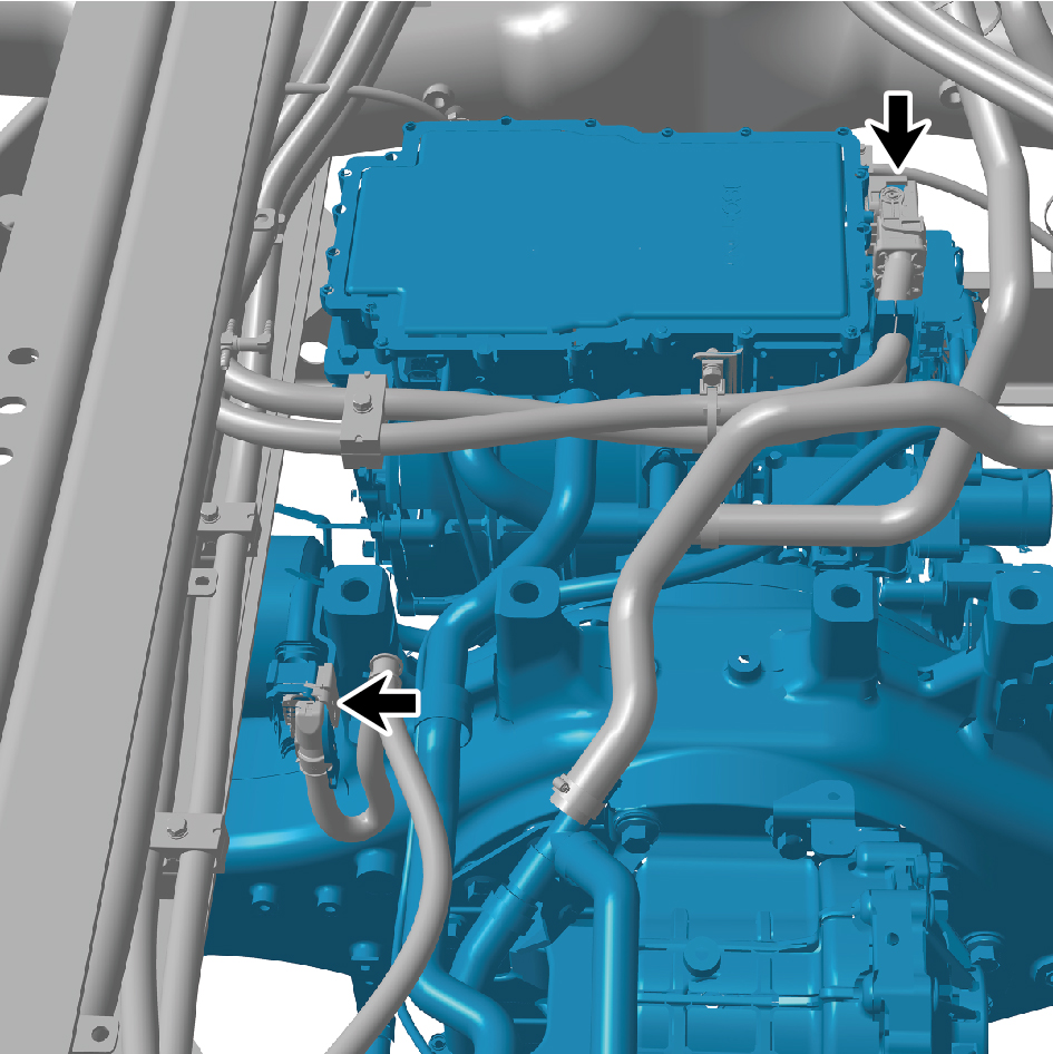
- intermediate axle.
25
Remove the 6 straps.
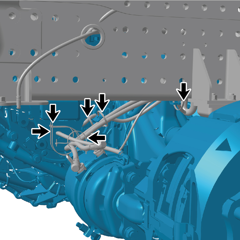
26
Disconnect the 2 harness connectors of the E-Axle Device
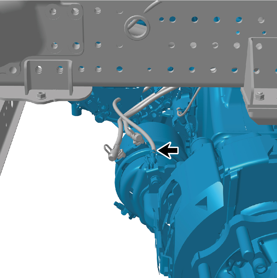
- intermediate axle.
27
Disconnect the 3 air pipes of the E-Axle Device -
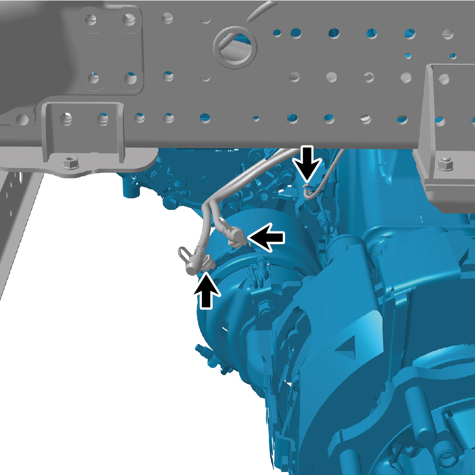
intermediate axle.
28
Remove the 6 straps.
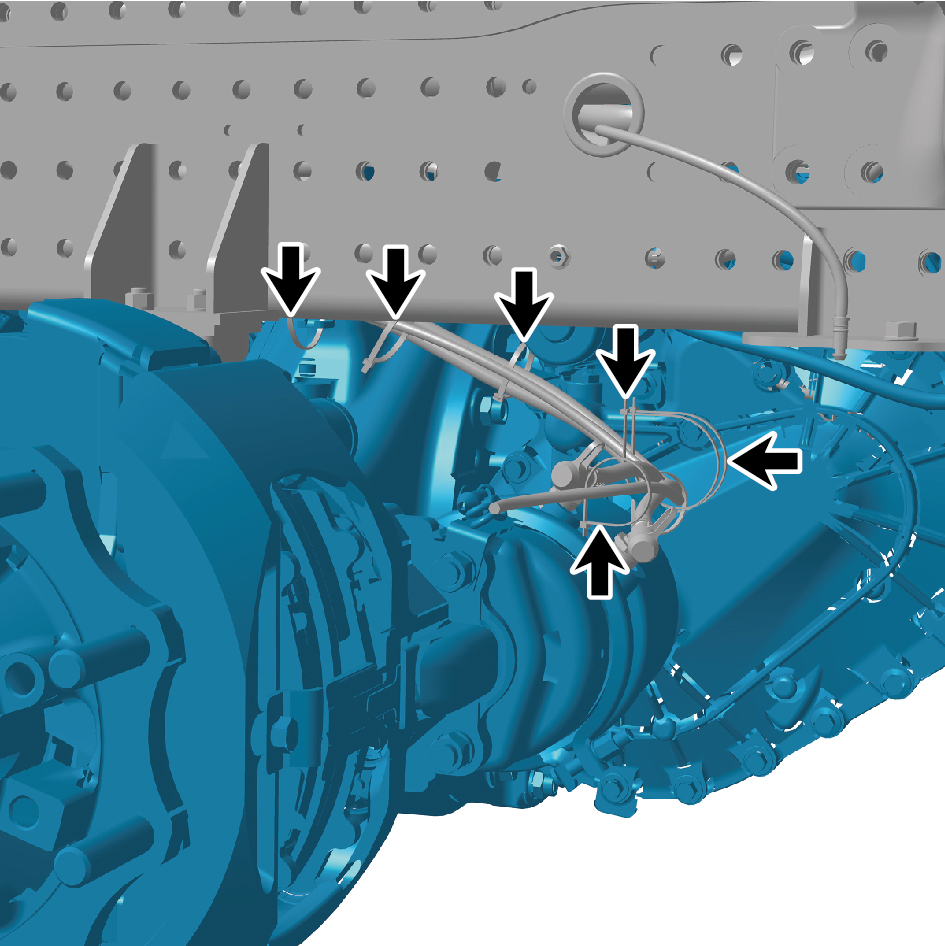
29
Disconnect the 2 harness connectors of the E-Axle Device
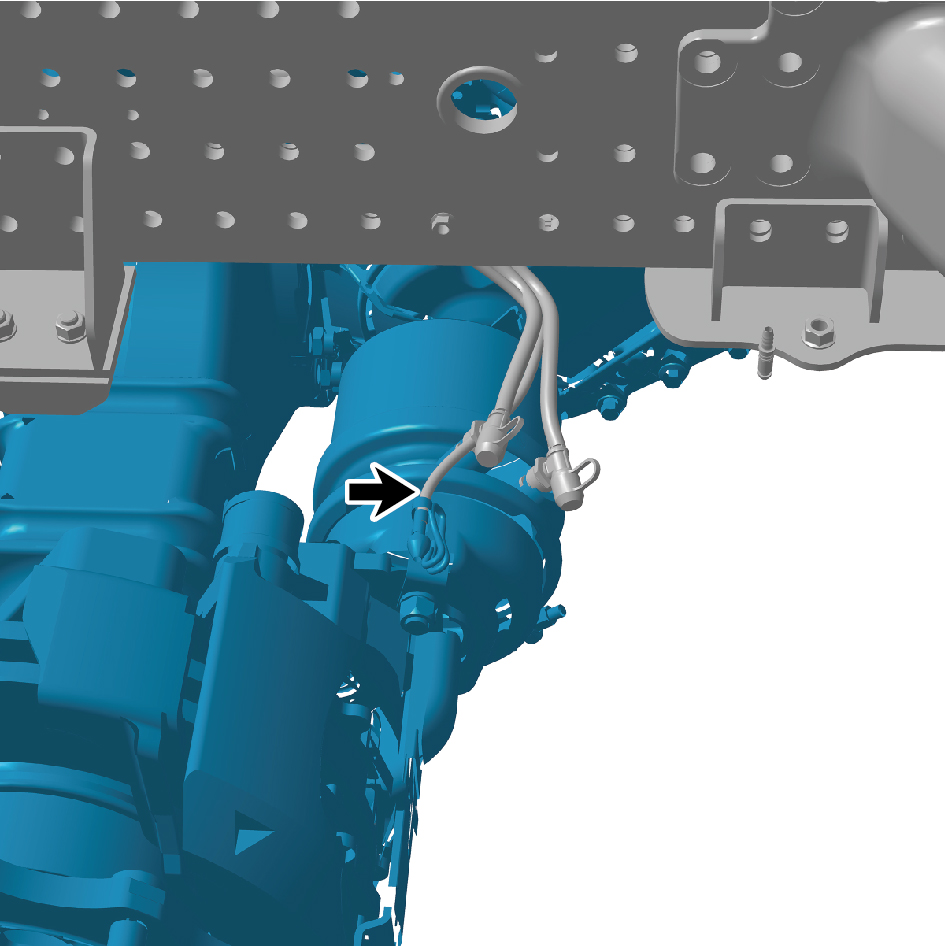
- intermediate axle.
30
Disconnect the 2 air pipes of the E-Axle Device -
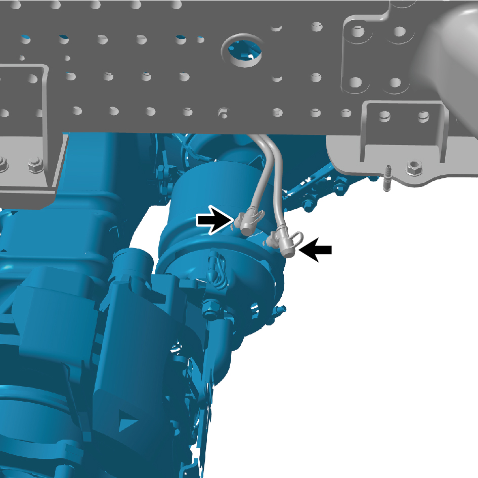
intermediate axle.
31
Disconnect the 2 water pipes of the E-Axle Device -
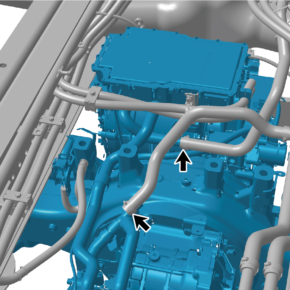
intermediate axle.
caution
Use a clean container to receive the discharged
coolant.
32
Remove 1 fixing bolt of the high-voltage wire harness
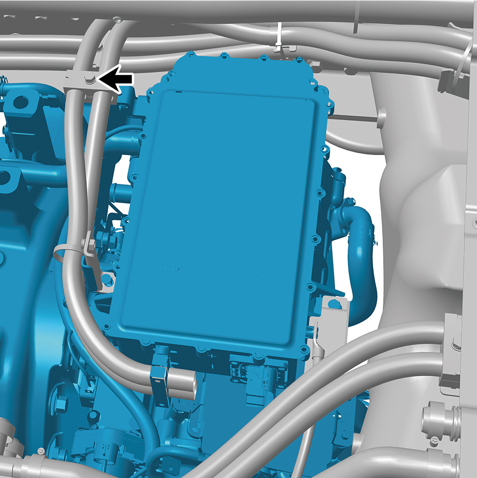
clamp on the E-Axle Device-intermediate axle.
33
Remove 3 fixing bolts on the E-Axle Device-intermediate
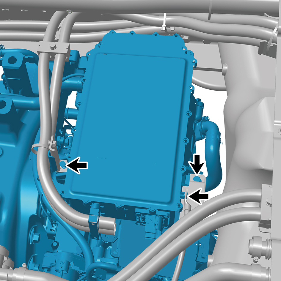
axle.
34
Disconnect the 1 harness connector of the E-Axle Device
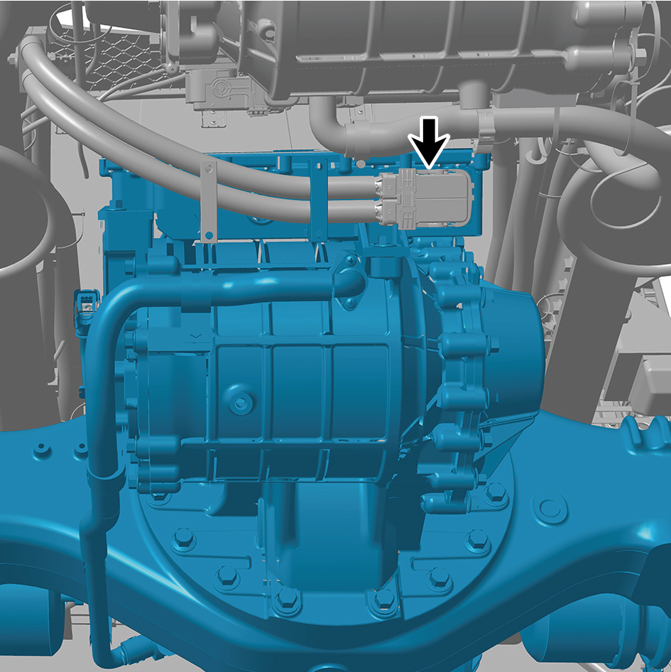
- intermediate axle.
35
Remove 4 fixing bolts of the fixed clamp for the high-
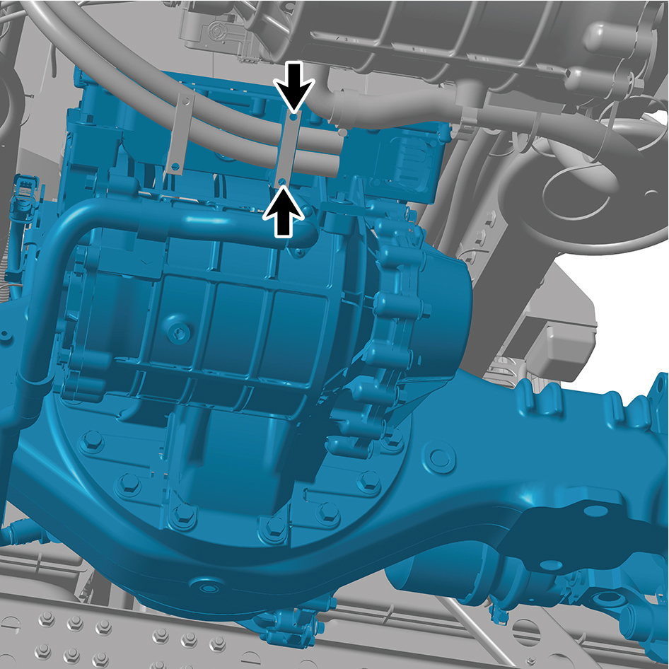
voltage wire harness of the E-Axle Device-intermediate
axle.
36
Using a lifting platform or other tools to remove the E-Axle
Device - intermediate axle.
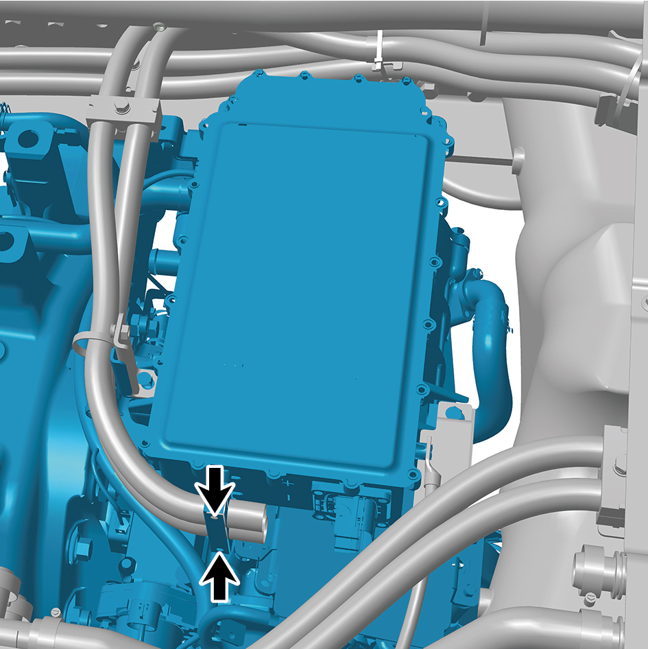
Installation Procedures
1
Use a lifting platform or other tools to move the E-Axle
Device - intermediate axle to the installation position.
2
Install 2 fixing bolts of the fixed clamp for the high-voltage
wire harness on the E-Axle Device-intermediate axle.
Torque: (12 ft-lb +/- .36) ft-lb
3
Connect 1 wire harness connector of the E-Axle Device-
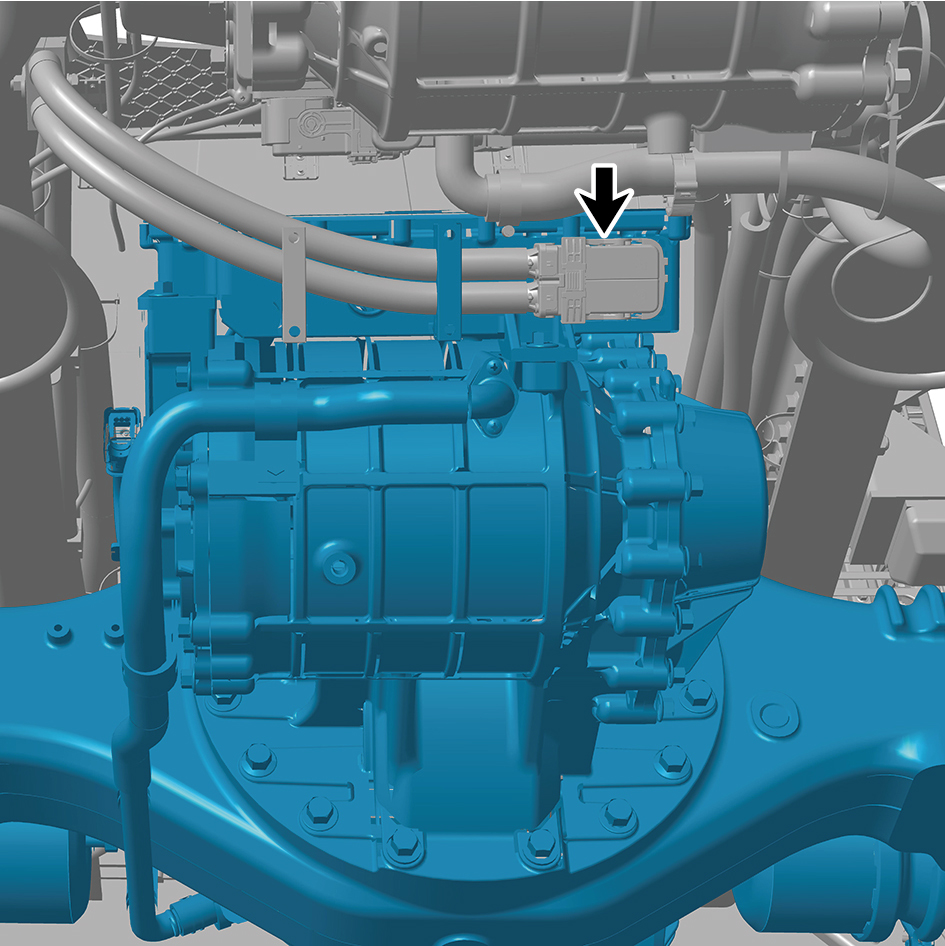
intermediate axle.
caution
The harness is firmly connected following the
principal of "insert until a click is heard for
confirmation".
4
Install 3 fixing bolts of the E-Axle Device-intermediate
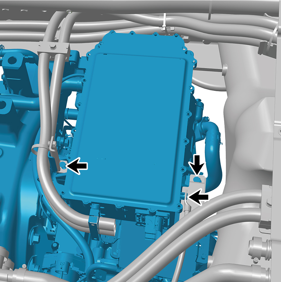
axle.
Torque: (18 ft-lb +/- 2 ft-lb) ft-lb
5
Install 1 fixing bolt of the high-voltage wire harness clamp
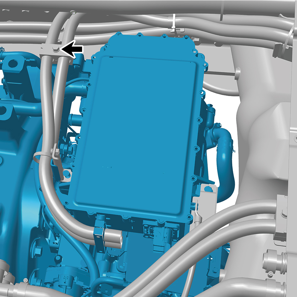
on the E-Axle Device-intermediate axle.
Torque:(9 ft-lb +/- .5 ft-lb) ft-lb
6
Connect the 2 water pipes of the E-Axle Device -
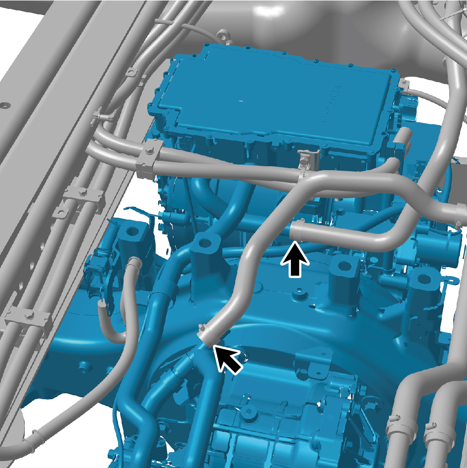
intermediate axle.
7
Connect the 2 air pipes of the E-Axle Device -
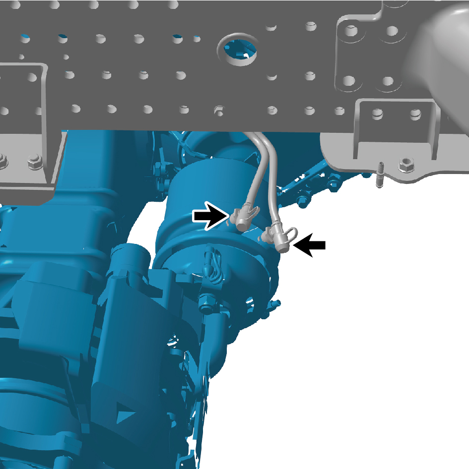
intermediate axle.
8
Connect 1 harness connector of the E-Axle Device -
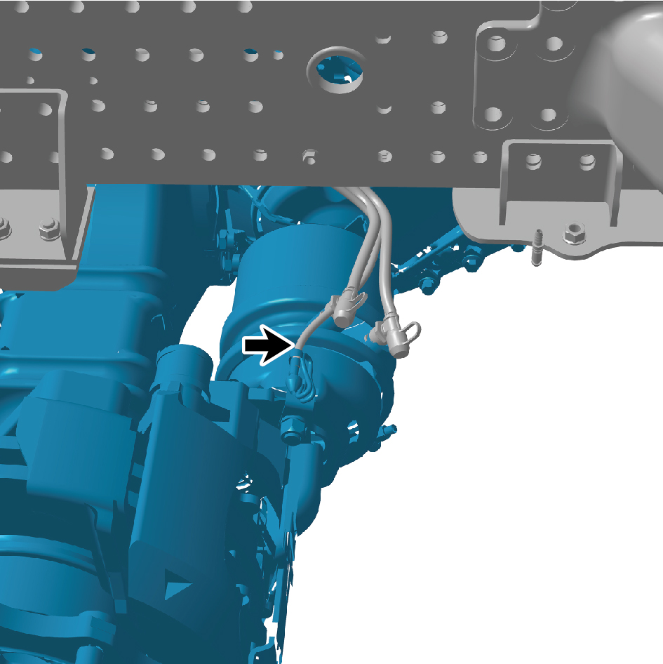
intermediate axle.
caution
The harness is firmly connected following the
principal of "insert until a click is heard for
confirmation".
9
Install the 6 straps.
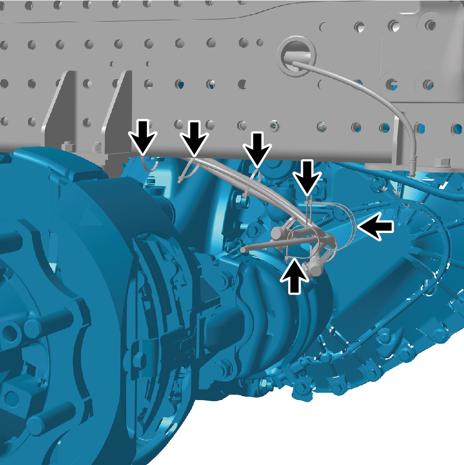
10
Connect the 3 air pipes of the E-Axle Device -
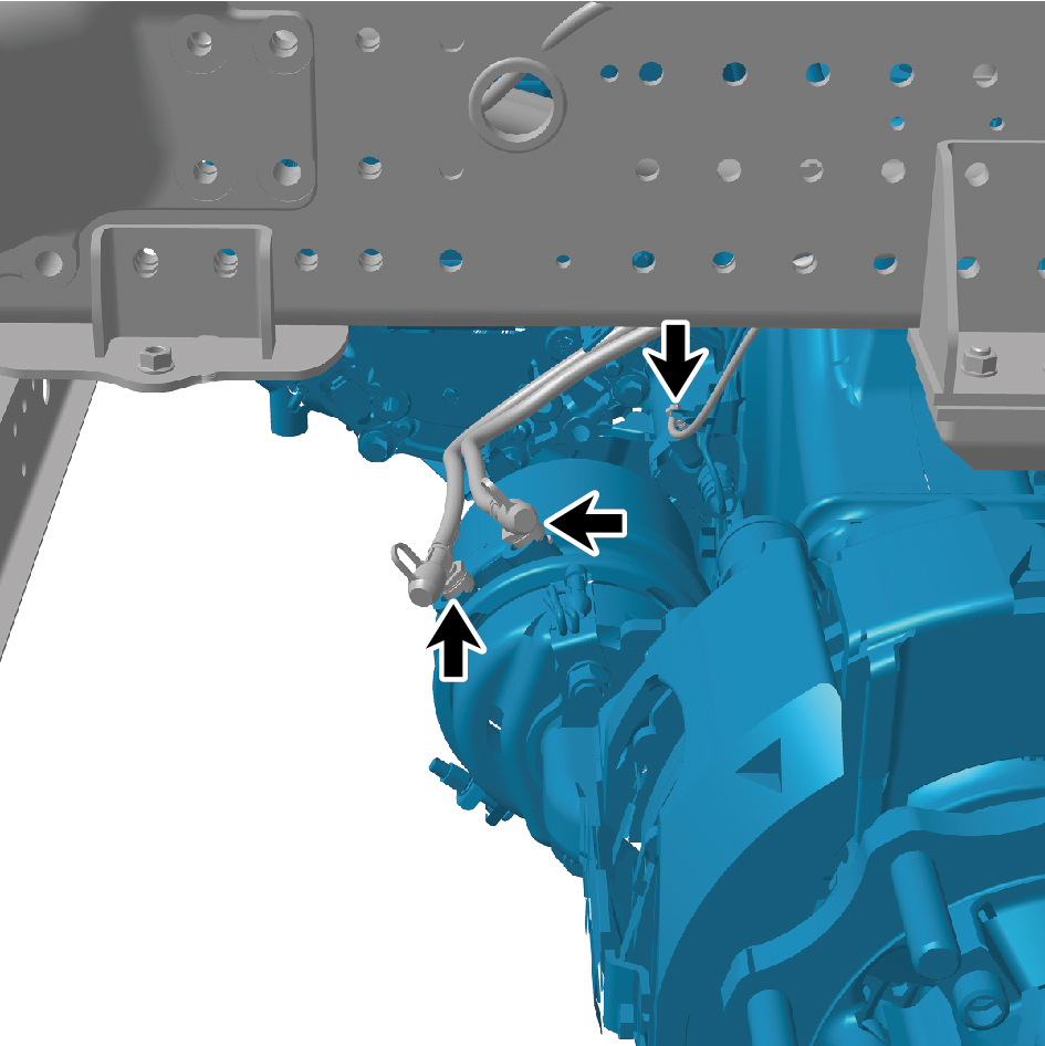
intermediate axle.
11
Connect 1 harness connector of the E-Axle Device -
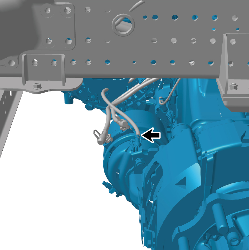
intermediate axle.
caution
The harness is firmly connected following the
principal of "insert until a click is heard for
confirmation".
12
Install the 6 straps.
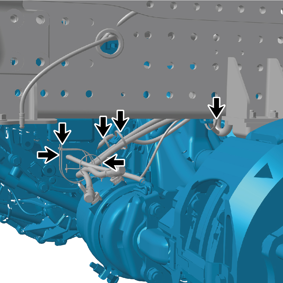
13
Connect 2 harness connector of the E-Axle Device -
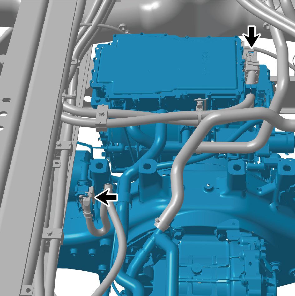
intermediate axle.
caution
The harness is firmly connected following the
principal of "insert until a click is heard for
confirmation".
14
Install the X-shaped control arm assembly (front).
15
Install the balance beam (right).
16
Install the rear air spring assembly - 280 (right front).
17
Install the rear air spring assembly - 260 (right front).
18
Install the rear wheel housing right front assembly.
19
Install the drive wheel (right front).
20
Install the balance beam (left).
21
Install the rear spring U-bolt.
22
Install the longitudinal thrust rod assembly.
23
Install the rear air spring assembly - 280 (left front).
24
Install the shock absorber assembly (rear).
25
Install the rear air spring assembly - 260 (left front).
26
Install the rear wheel housing left front assembly.
27
Install the drive wheel (left front).
28
Install the corrugated plate.
29
Install the fifth wheel assembly.
30
Fill coolant in the power system.
31
Lower the rear end of the vehicle.
32
Perform power-on of the high voltage system.
33
Connect the battery negative cable.
34
Close the front flip cover plate.
35
Close the door.
4.1.7.2 Replacement of E-Axle Device - Rear Axle
Axle
Removal Procedures
1
Release air pressure from the brake system.
2
Open the door.
3
Open the front flip cover plate.
4
Disconnect the battery negative cable.
5
Perform power-off of high voltage system.
6
Jack the rear end of the vehicle.
7
Drain coolant from the power system.
8
Remove the rear wheel housing upper body.
9
Remove the drive wheel (rear left).
10
Remove the height adjustment device assembly (left).
11
Remove the rear left wheel housing middle body
assembly.
12
Remove the rear left wheel housing rear body assembly.
13
Remove the rear air spring assembly - 260 (rear left).
14
Remove the shock absorber assembly (rear).
15
Remove the rear air spring assembly - 280 (rear left).
16
Remove the longitudinal thrust rod assembly.
17
Remove the rear spring U-bolt.
18
Remove the rear spring U-bolt 2.
19
Remove the balance beam (left).
20
Remove the drive wheel (rear right).
21
Remove the height adjustment device assembly (right).
22
Remove the rear right wheel housing middle body
assembly.
23
Remove the rear right wheel housing rear body assembly.
24
Remove the rear air spring assembly - 260 (rear right).
25
Remove the rear air spring assembly - 280 (rear right).
26
Remove the balance beam (right).
27
Remove the dual channel module assembly.
28
Remove the X-shaped control arm assembly (rear).
28
Disconnect the 2 harness connectors of the E-Axle Device
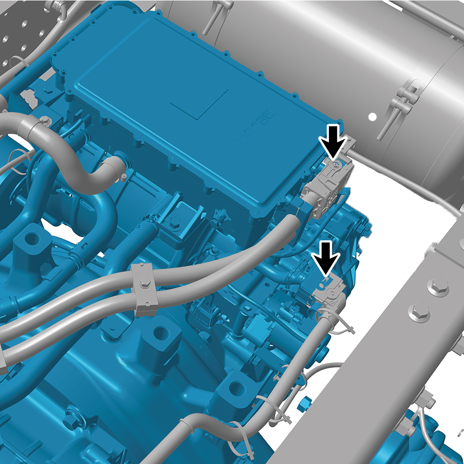
- rear axle.
29
Remove the 4 straps.
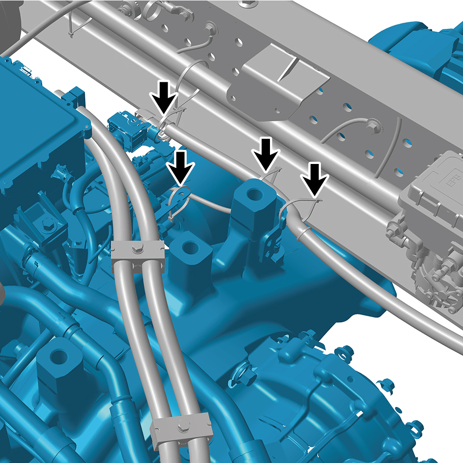
30
Disconnect the 2 harness connectors of the E-Axle Device
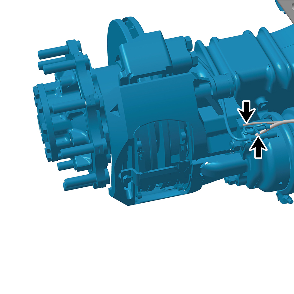
- rear axle.
31
Disconnect the 2 harness connectors of the E-Axle Device
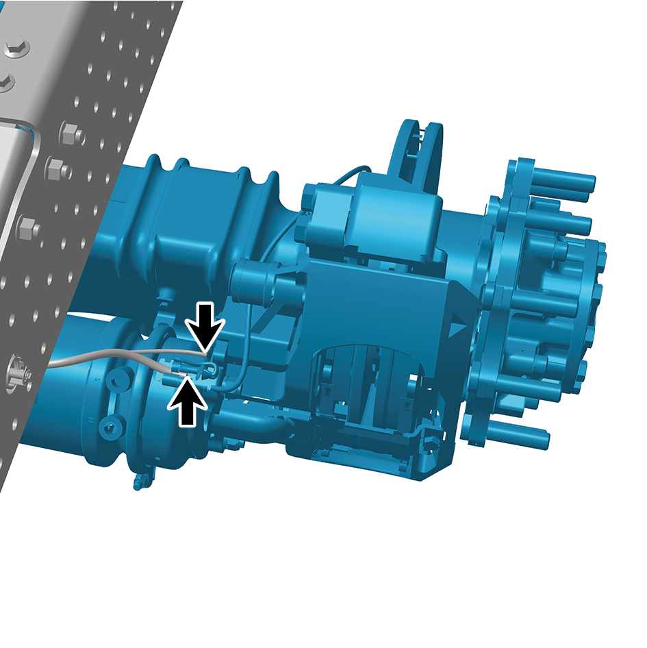
- rear axle.
32
Disconnect the 2 water pipes of the E-Axle Device - rear
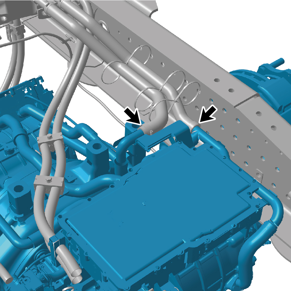
axle.
caution
Use a clean container to receive the discharged
coolant.
33
Remove the 2 fixing bolts of the E-Axle Device - rear axle.
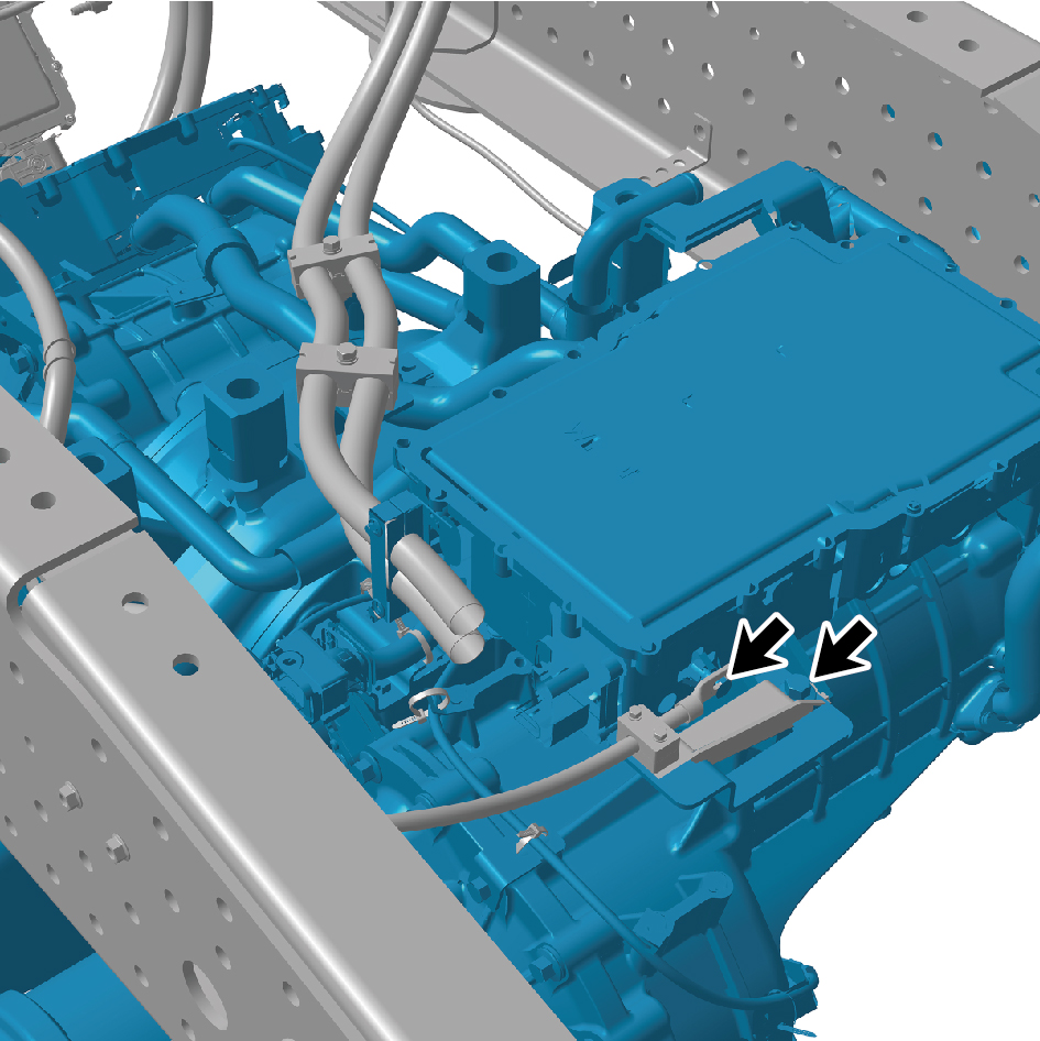
34
Remove the 2 fixing bolts of the high-voltage wire harness
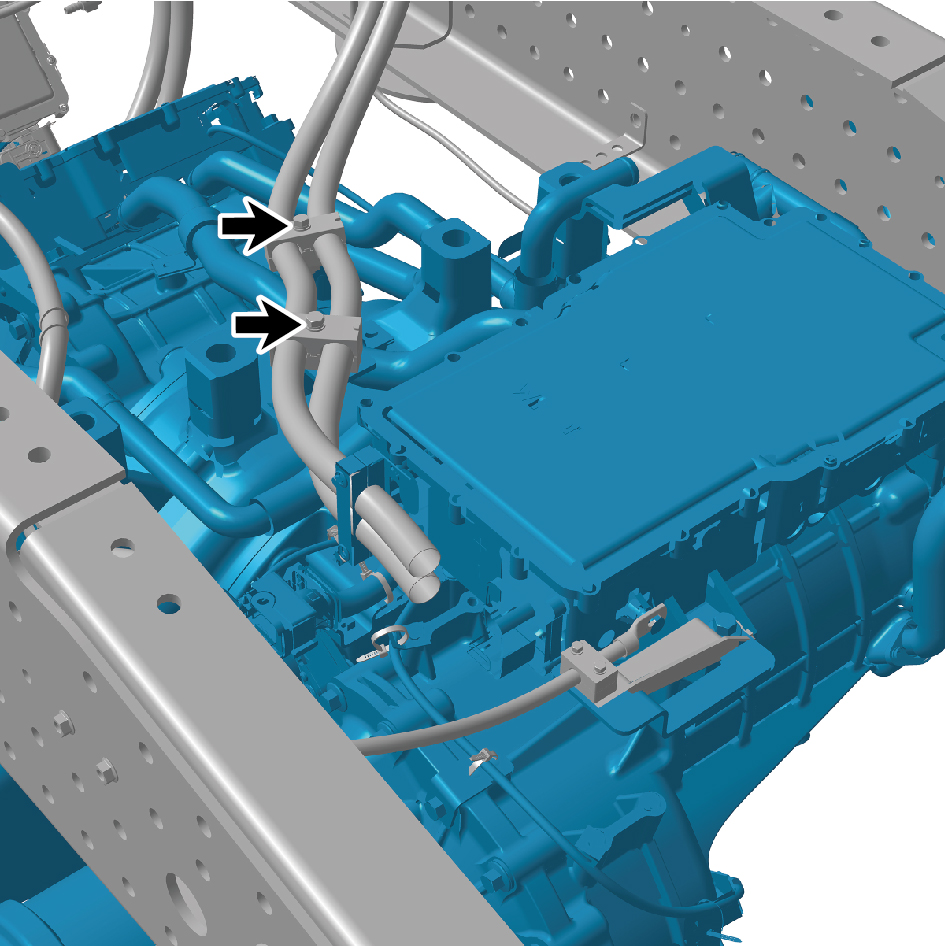
clamp on the E-Axle Device - the rear axle.
35
Disconnect the 1 harness connectors of the E-Axle Device
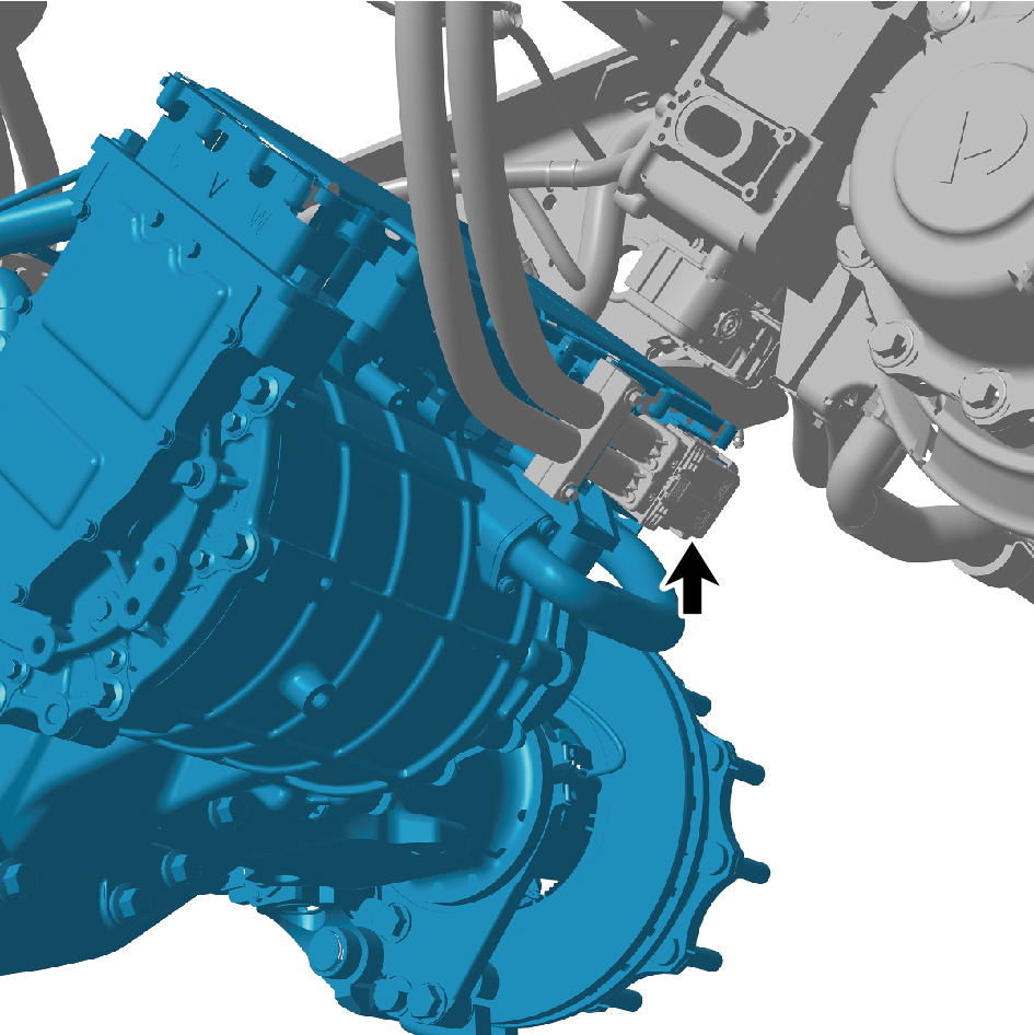
- rear axle.
36
Remove the 4 fixing bolts of the E-Axle Device - rear axle.
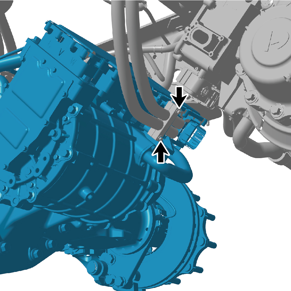
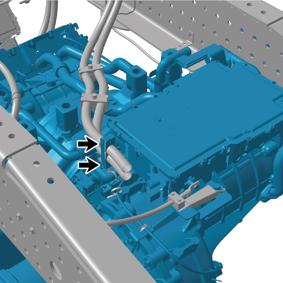
37
Disconnect the 2 air pipes of the E-Axle Device - rear axle.
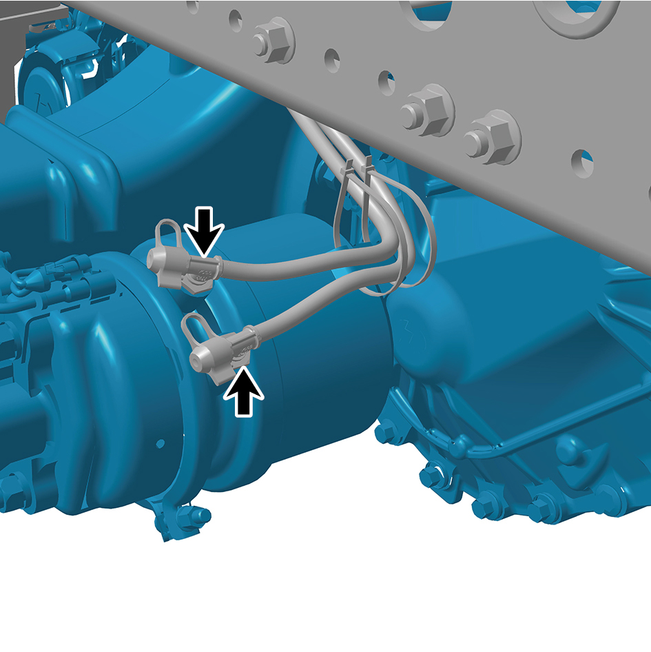
38
Remove the 2 straps of the E-Axle Device - rear axle.
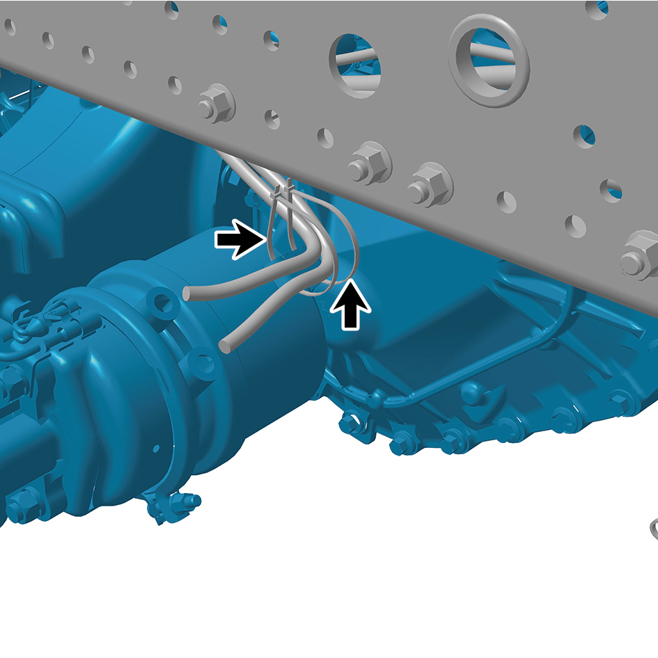
39
Disconnect the 3 air pipes of the E-Axle Device - rear axle.
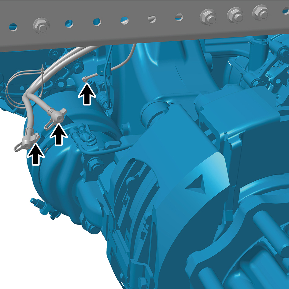
40
Remove the 2 straps of the E-Axle Device - rear axle.
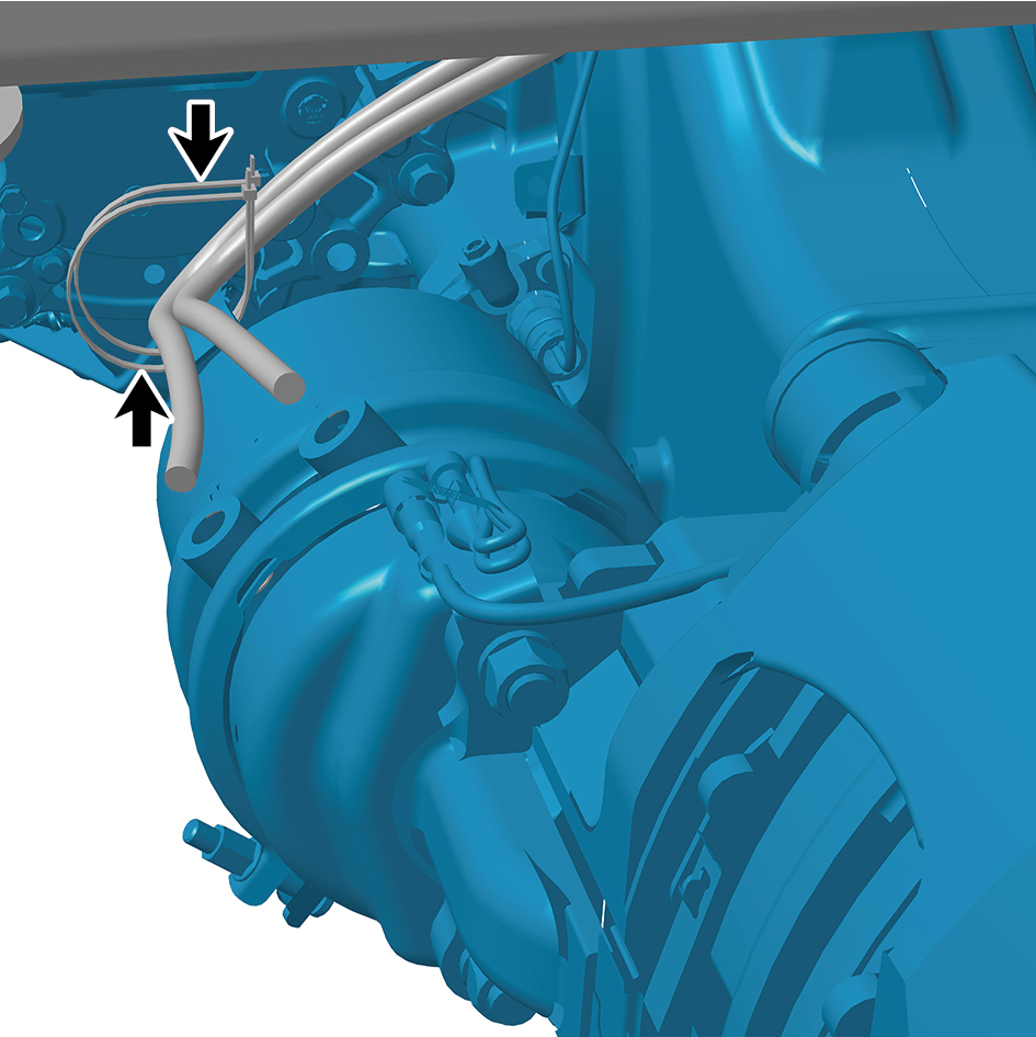
41
Use a lifting platform or other tools to remove the E-Axle
Device - rear axle.
Installation Procedures
1
Use a lifting platform or other tools to move the E-Axle
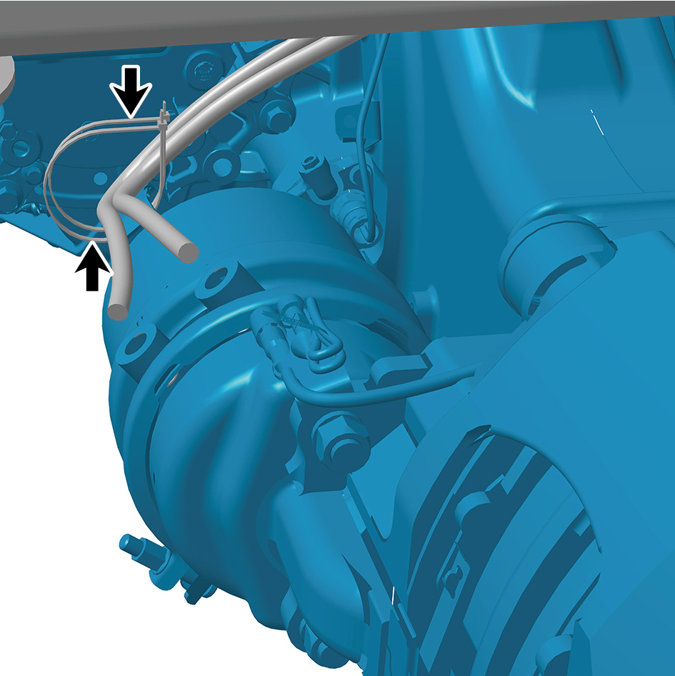
Device - rear axle to the installation position.
2
Install the 2 straps of the E-Axle Device - rear axle.
3
Connect the 3 air pipes of the E-Axle Device - rear axle.
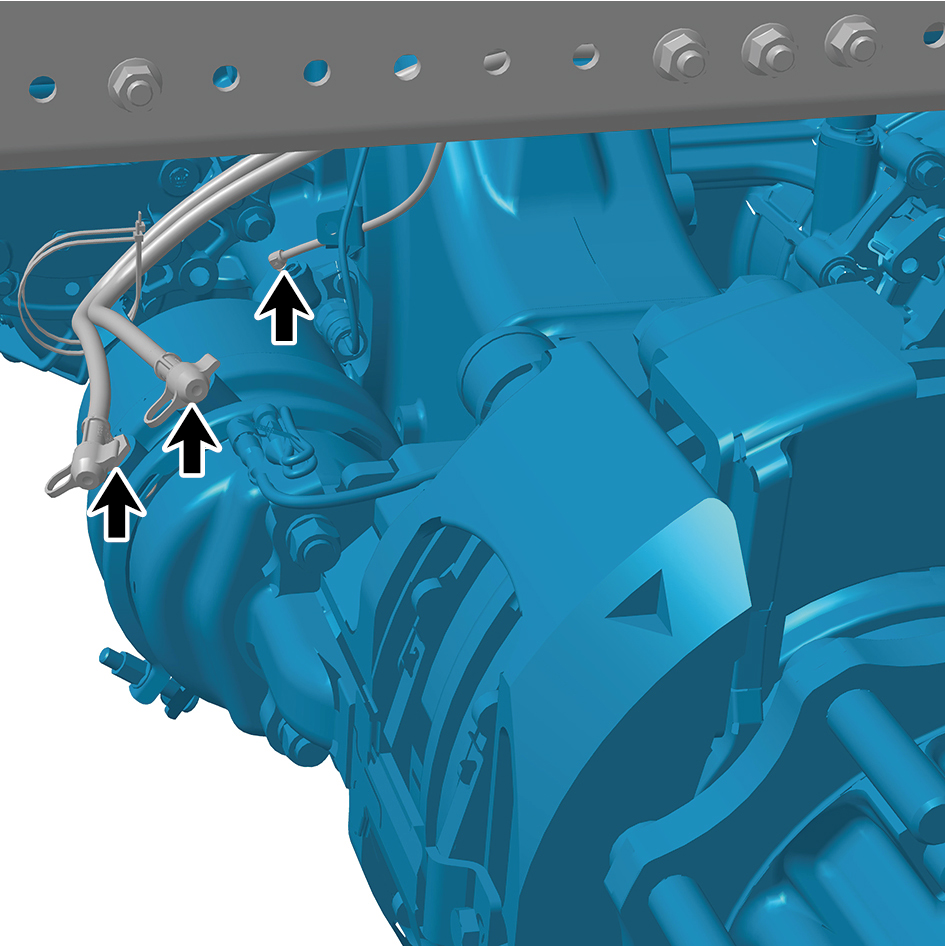
4
Install the 2 straps of the E-Axle Device - rear axle.
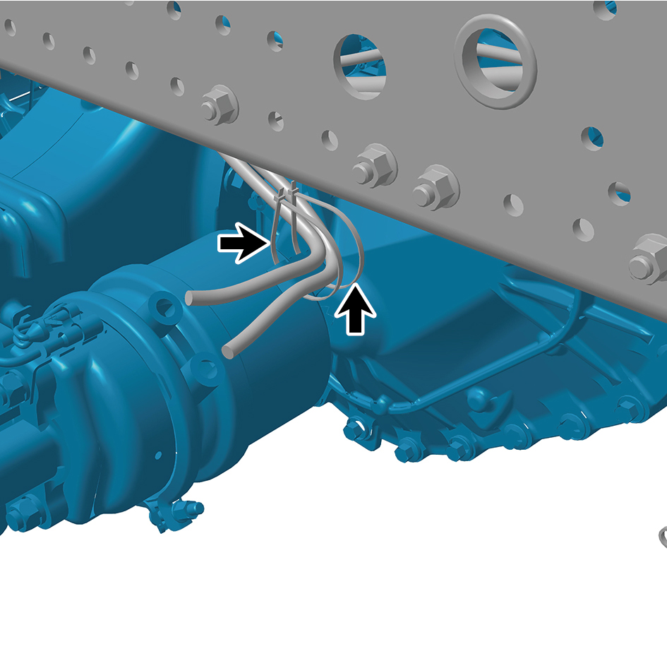
5
Connect the 2 air pipes of the E-Axle Device - rear axle.
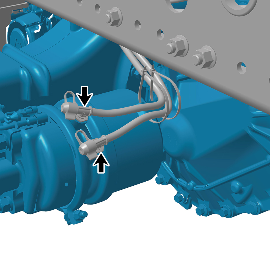
6
Install the 4 fixing bolts of the high-voltage wire harness
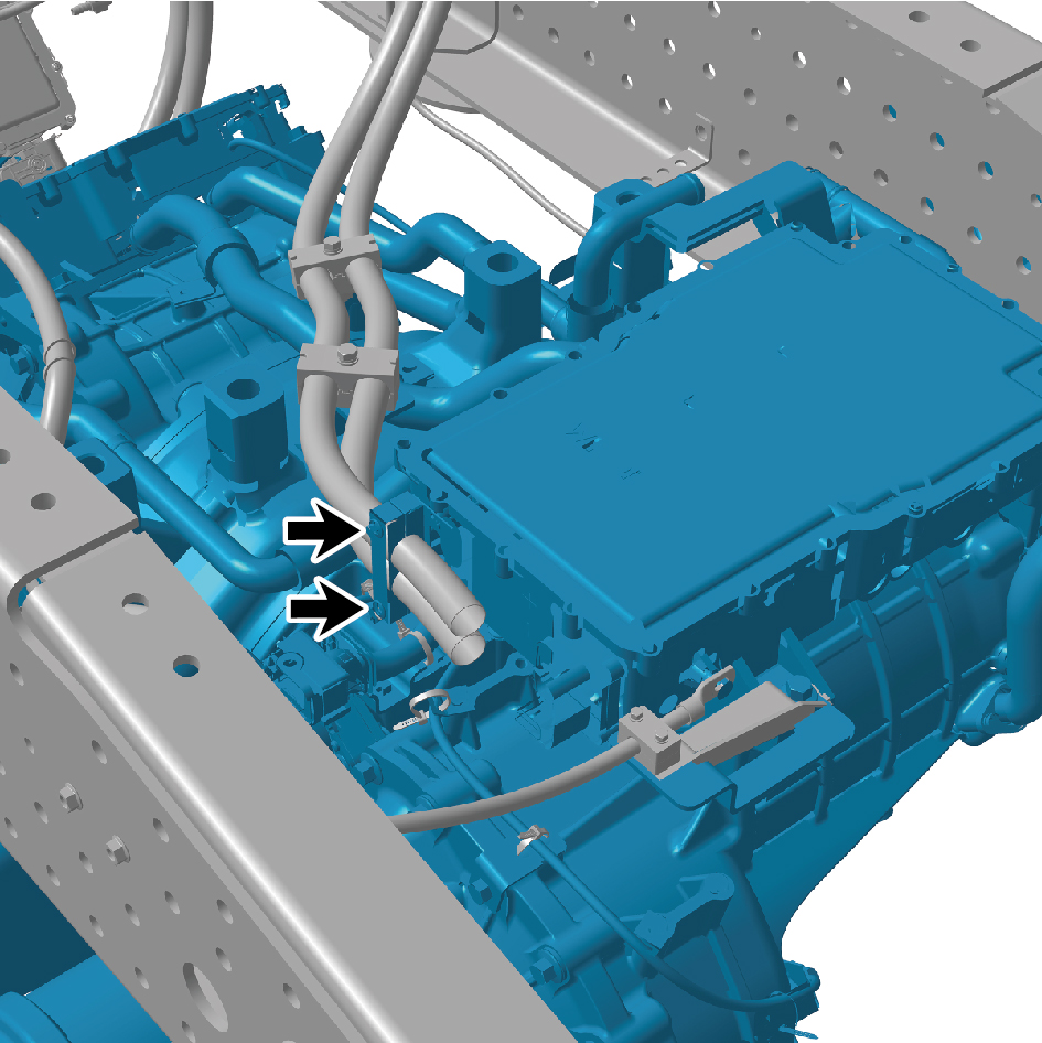
clamp on the E-Axle Device - the rear axle.
Torque: (12 ft-lb +/- .36) ft-lb
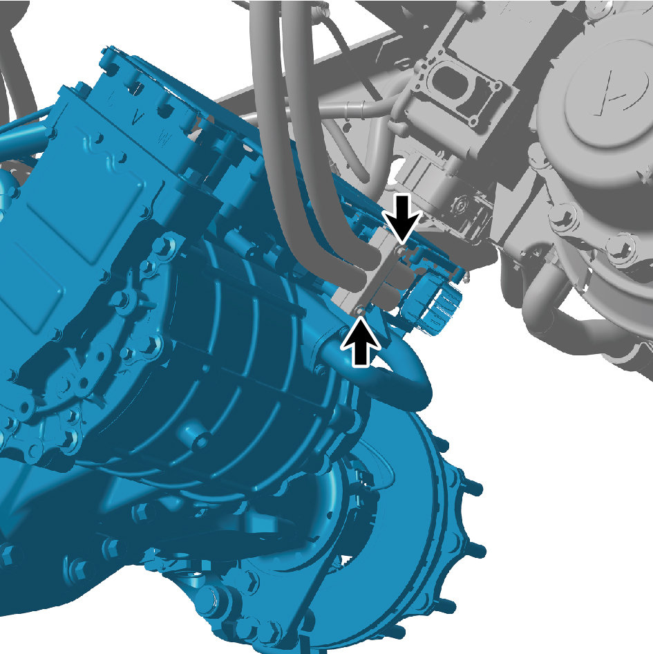
7
Connect the 1 harness connectors of the E-Axle Device -
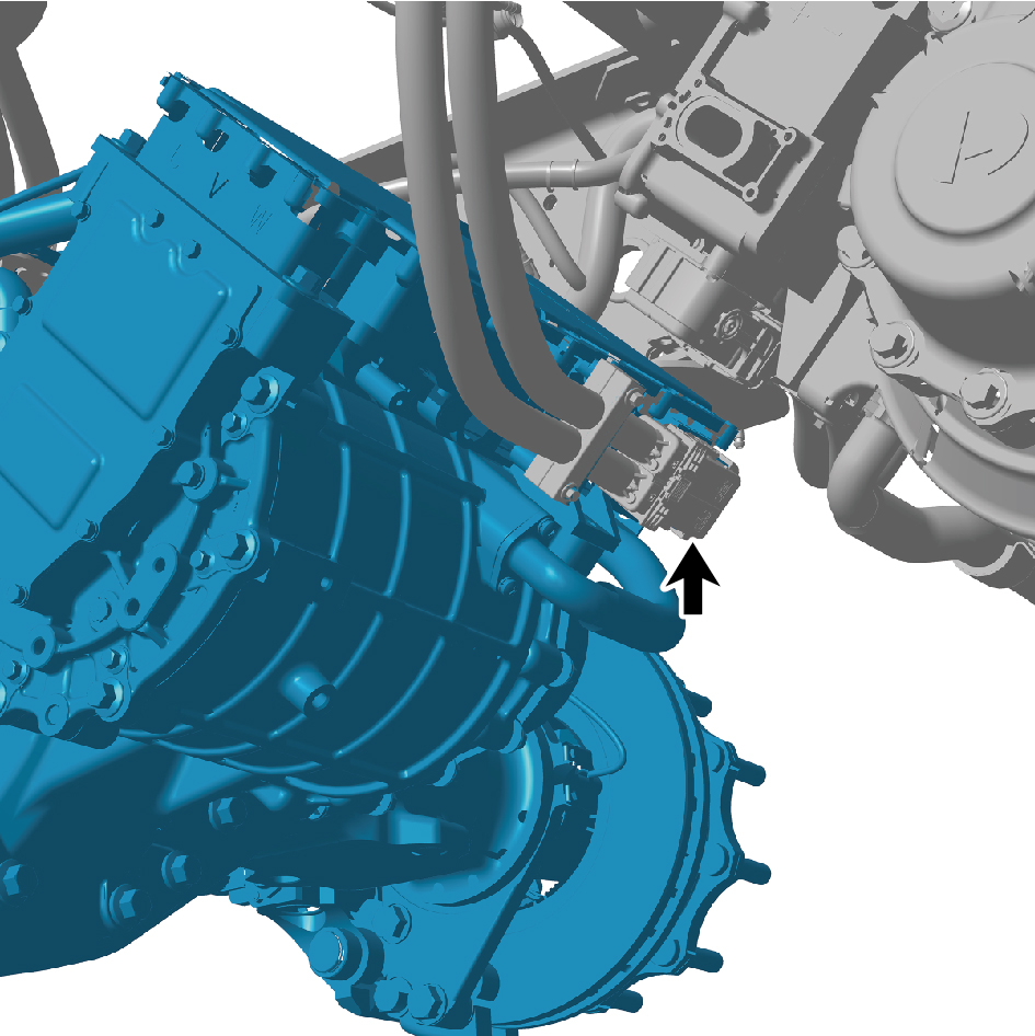
rear axle.
caution
The harness is firmly connected following the
principal of "insert until a click is heard for
confirmation".
8
Install the 2 fixing bolts of the high-voltage wire harness
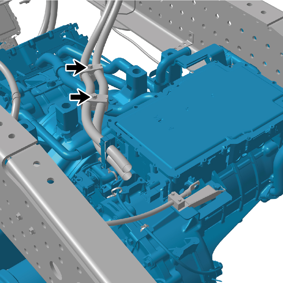
clamp on the E-Axle Device - the rear axle.
Torque:(9 ft-lb +/- .5 ft-lb) ft-lb
9
Install the 2 fixing bolts of the E-Axle Device - rear axle.
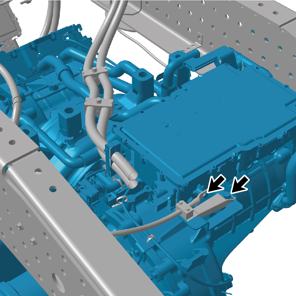
Torque: (18 ft-lb +/- 2 ft-lb) ft-lb
10
Connect the 2 water pipes of the E-Axle Device - rear
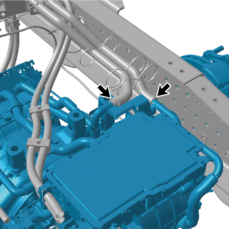
axle.
11
Connect the 2 harness connectors of the E-Axle Device -
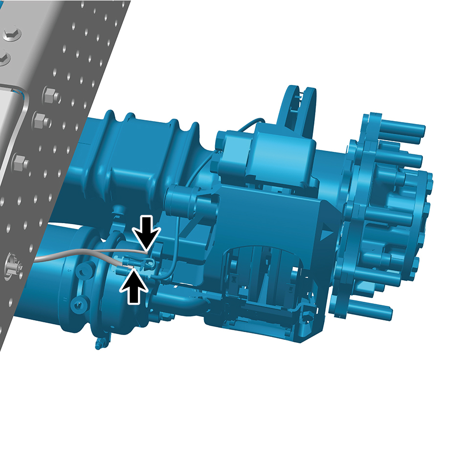
rear axle.
caution
The harness is firmly connected following the
principal of "insert until a click is heard for
confirmation".
12
Connect the 2 harness connectors of the E-Axle Device -
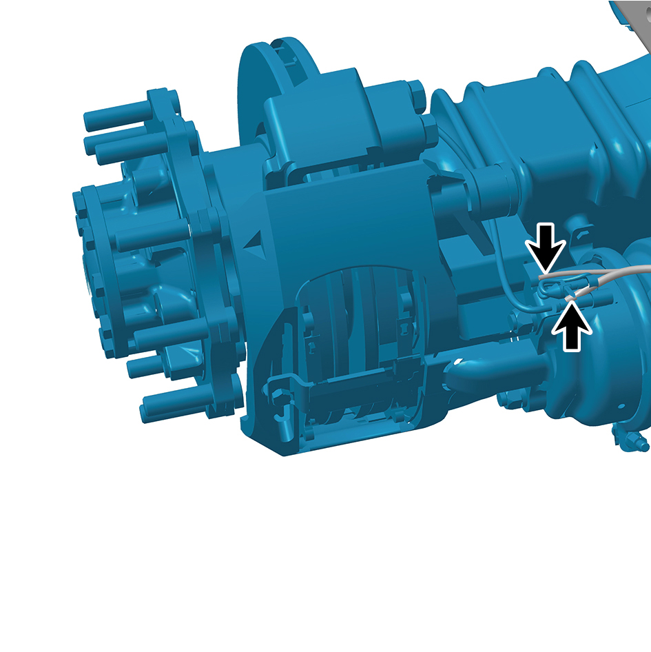
rear axle.
caution
The harness is firmly connected following the
principal of "insert until a click is heard for
confirmation".
13
Install the 4 straps of the E-Axle Device - rear axle.
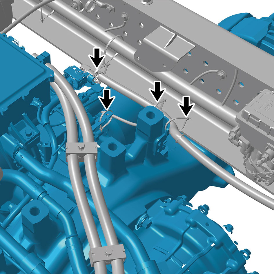
14
Connect the 2 harness connectors of the E-Axle Device -
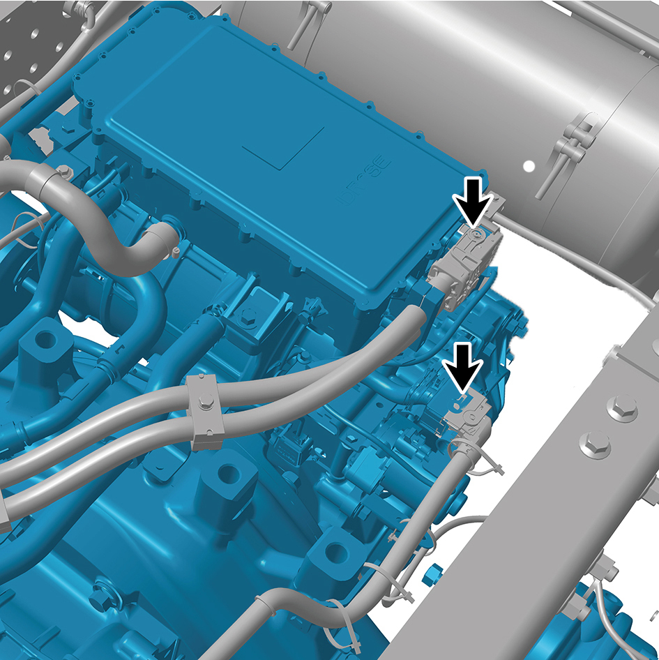
rear axle.
caution
The harness is firmly connected following the
principal of "insert until a click is heard for
confirmation".
16
Install the X-shaped control arm assembly (rear).
17
Install the dual channel module assembly.
18
Install the balance beam (right).
19
Install the rear air spring assembly - 280 (rear right).
20
Install the rear air spring assembly - 260 (rear right).
21
Install the rear right wheel housing rear body assembly.
22
Install the rear right wheel housing middle body assembly.
23
Install the height adjustment device assembly (right).
24
Install the drive wheel (rear right).
25
Install the balance beam (left).
26
Install the rear spring U-bolt 2.
27
Install the rear spring U-bolt.
28
Install the longitudinal thrust rod assembly.
29
Install the rear air spring assembly - 280 (rear left).
30
Install the shock absorber assembly (rear).
31
Install the rear air spring assembly - 260 (rear left).
32
Install the rear left wheel housing rear body assembly.
33
Install the rear left wheel housing middle body assembly.
34
Install the height adjustment device assembly (left).
35
Install the drive wheel (rear left).
36
Install the rear wheel housing upper body.
37
Fill coolant in the power system.
38
Lower the rear end of the vehicle.
39
Perform power-on of the high voltage system.
40
Connect the battery negative cable.
41
Close the front flip cover plate.
42
Close the door.
caution
After replacing the parts, it is necessary to
recalibrate the height.